Embed Size (px)
Citation preview

Preparation and Characterisation of Radiation-Grafted Membranes for Fuel Cells.
NADIA WALSBY
Laboratory of Polymer Chemistry Department of Chemistry
University of Helsinki Helsinki Finland
National Graduate School of Electrochemical Science and Technology
of Polymers and Membranes including Biomembranes
ACADEMIC DISSERTATION
To be presented with the permission of the Faculty of Science of the University of Helsinki for public criticism in Auditorium XII of the University Main Building on
17 August 2001, at 12 o'clock.
Helsinki 2001

In memory of that infuriating and much loved old lady, Thora Walsby.
ISBN 952-91-3646-3
Helsinki 2001 Yliopistopaino
iii
ACKNOWLEDGEMENTS This work was carried out at the Laboratory of Polymer Chemistry of the University of Helsinki during the years 1998-2001. The irradiation and grafting took place at SmopTech Ltd, Åbo. My thanks are due to the many people who have helped me over this period. Above all, I would like to thank Professor Franciska Sundholm for taking me on, supervising and encouraging me throughout my research. I will remember my co-workers on this project with great affection. In particular, I am indebted to Tanja Kallio at Helsinki University of Technology, Peter Holmlund at Åbo Akademi, Dr Mikael Paronen and Dr Sami Hietala for help and advice. I would like to thank all the staff at the Laboratory of Polymer Chemistry for making it such a pleasant place to work. I owe a special debt to Heljä Heikkilä, who has, with boundless patience, helped me with all the problems that beset a foreigner. The different facets of membrane characterisation have allowed me to work with many people, and in addition to those already named, I am grateful to Professor Göran Sundholm at Helsinki University of Technology, Jari Ihonen and Peter Gode at the Royal Institute of Technology at Stockholm for the electrochemical measurements, Dr Kenneth Ekman at SmopTech for help with the irradiation equipment, Kaija Jokela and Docent Ritva Serimaa at the University of Helsinki for the x-ray measurements, Hanna Ericson at Chalmers University for the Raman characterisation and Docent Sirkka-Liisa Maunu at the University of Helsinki for the NMR characterisation. I am grateful to the Academy of Finland and to the ESPOM graduate school for funding. Finally I would like to thank my parents for their unfailing support and my brothers for being their inimitable selves. Helsinki, June 2001 Nadia Walsby

iv
ABSTRACT Proton conducting membranes for fuel cell applications have been prepared by electron beam irradiation of pre-formed fluoropolymer films, grafting of styrene and subsequent sulfonation. The influence of the preparation conditions and the role of the initial fluoropolymer are investigated. In poly(vinylidene fluoride), the absorbed dose during irradiation determines the initial rate of grafting and the graft penetration and saturation degrees of grafting. Lower doses lead to slower grafting rates and a lower graft penetration degree of grafting. Higher grafting temperatures increase the initial grafting rate but lower the saturation degree of grafting. The diluent used in the grafting reaction has a considerable effect not only on the kinetics, but also on the tensile properties and surface aspect of the grafted materials. Films grafted in propanol, which does not swell the polystyrene grafts, break with considerably less elongation and have rougher surfaces than films grafted in the polystyrene-swelling toluene. The sulfonation of styrene grafted poly(vinylidene fluoride) films in chlorosulfonic acid/dichloroethane solutions proceeds by a reaction front mechanism. High concentrations favour side-reactions and lead to a loss of ion-exchange capacity and conductivity, but also to an increase in the resistance to a hydrogen peroxide solution. The kinetics of the grafting reaction vary according to the matrix material, but by changing the absorbed dose membranes based on different fluoropolymers with similar degrees of grafting and even polystyrene distributions can be prepared. The same sulfonation conditions can be used for most of the styrene-grafted fluoropolymers. Membranes based on different fluoropolymers differ most in their water uptake from liquid water, which varies with the crystallinity. Calorimetric measurements show that higher water uptakes are accompanied by larger pores in the water-swollen materials. The choice of matrix has an indirect effect on all the properties influenced by the water uptake; its role is one of restricting host to the polystyrene sulfonic acid grafts. Electrochemical measurements show that membranes with high water uptakes have high conductivities but low open circuit potentials. When tested in a fuel cell the lifetime is short, and cracks appear at the interface between active and inactive area. This mechanical failure is attributed to dimensional changes brought about by variations in the humidification level. Some degradation of the polystyrene sulfonic acid grafts also takes place. Experiments on membranes with lower degrees of grafting suggest that the lifetime can be extended by reducing the water uptake and optimising the contact between membrane and electrode.

v
ABBREVIATIONS BVPE bis(vinyl phenyl) ethane DMFC direct methanol fuel cell DOG degree of grafting DSC differential scanning calorimetry DVB divinyl benzene EB electron beam ETFE poly(ethylene-alt-tetrafluoroethylene) EW equivalent weight FEP poly(tetrafluoroethylene-co-hexafluoropropylene) HFP hexafluoropropylene IEC ion-exchange capacity NMR nuclear magnetic resonance OCP open circuit potential PEFC polymer electrolyte fuel cell PFA poly(tetrafluoroethylene-co-perfluorovinylether) PS polystyrene PSSA poly(styrene sulfonic acid) PTFE poly(tetrafluoroethylene) PVDF poly(vinylidene fluoride) PVF poly(vinyl fluoride) RH relative humidity SAXS small angle x-ray scattering TAC triallyl cyanurate SEM scanning electron microscopy WAXS wide-angle x-ray scattering WISE wideline separation XRD x-ray diffraction SYMBOLS λ number of water molecules per sulfonic group σ proton conductivity T1H proton relaxation time

vi
LIST OF ORIGINAL PAPERS This thesis is based on the following papers, hereafter referred to by the associated Roman numerals. A little new material is also presented.
I. N. Walsby, M. Paronen, J. Juhanoja and F. Sundholm, Radiation grafting of styrene to PVDF films in propanol: the influence of the solvent and the synthesis conditions, J. Polym. Sci., Part A: Polym. Chem., 38, 1512 (2000).
II. N. Walsby, M. Paronen, J. Juhanoja and F. Sundholm, Sulfonation of styrene grafted PVDF films, J. Appl. Polym. Sci., 81, 1572 (2001).
III. N. Walsby, F. Sundholm, T. Kallio and G. Sundholm, Radiation grafted ion-exchange membranes. Influence of the initial matrix on the synthesis and structure., J. Polym. Sci., Part A: Polym. Chem., accepted.
IV. N. Walsby, S. Hietala, S. L. Maunu, F. Sundholm, T. Kallio and G. Sundholm, Water in different polystyrene sulfonic acid grafted fluoropolymers, J. Appl. Polym. Sci., submitted.
V. T. Kallio, M. Lundström, G. Sundholm, N. Walsby and F. Sundholm, Electrochemical characterization of radiation grafted ion-exchange membranes, J. Appl. Electrochem., submitted.
VI. M. Elomaa, S. Hietala, M. Paronen, N. Walsby, K. Jokela, R. Serimaa, M. Torkkeli, T. Lehtinen, G. Sundholm and F. Sundholm, The state of water and the nature of ion clusters in crosslinked proton conducting membranes of styrene grafted and sulfonated poly(vinylidene fluoride), J. Mater. Chem., 10, 2678 (2000)

vii
CONTENTS
ACKNOWLEDGEMENTS .....................................................................................iii
ABSTRACT ................................................................................................................. iv
ABBREVIATIONS..................................................................................................... v
SYMBOLS .................................................................................................................... v
LIST OF ORIGINAL PAPERS .............................................................................. vi
CONTENTS ................................................................................................................vii
1. INTRODUCTION ............................................................................................... 1
2. FUEL CELLS ....................................................................................................... 1
2.1 Brief history....................................................................................................... 1
2.2 Types of fuel cell.............................................................................................. 2
2.3 Principle of operation of a PEFC ................................................................. 2
2.4 The polymer electrolyte during fuel cell operation. ................................ 3
2.5 Issues remaining ............................................................................................... 3
3. POLYMER ELECTROLYTE MEMBRANES ........................................... 4
3.1 Requirements..................................................................................................... 4
3.2 Perfluorinated membranes ............................................................................. 4 3.2.1 Structure........................................................................................................ 5 3.2.2 Properties ...................................................................................................... 6 3.2.3 Performance .................................................................................................. 6
3.3 Other options..................................................................................................... 6
3.4 Radiation-grafted membranes....................................................................... 7 3.4.1 Irradiation, grafting and sulfonation. ............................................................ 8 3.4.2 Structural characteristics............................................................................... 9 3.4.3 Properties ...................................................................................................... 9 3.4.4 Electrochemical data................................................................................... 10 3.4.5 Degradation................................................................................................. 12
viii
3.4.6 Remaining questions................................................................................... 12
4. EXPERIMENTAL............................................................................................ 13
4.1 Materials........................................................................................................... 13
4.2 Irradiation, grafting and sulfonation.......................................................... 13
4.3 Characterisation.............................................................................................. 14
5. RESULTS AND DISCUSSIONS.................................................................. 15
5.1 Irradiation and grafting................................................................................. 15 5.1.1 Grafting kinetics in propanol ...................................................................... 15 5.1.2 Influence of the diluent on the grafting kinetics ......................................... 15 5.1.3 Properties of PS grafted PVDF................................................................... 16 5.1.4 Practical conclusions on the grafting reaction ............................................ 18
5.2 Sulfonation....................................................................................................... 18
5.3 Influence of the initial matrix polymer..................................................... 21 5.3.1 Irradiation, grafting and sulfonation ........................................................... 21 5.3.2 Structure and water uptake.......................................................................... 22 5.3.3 Other properties .......................................................................................... 26 5.3.4 Electrochemical characteristicsV................................................................. 28 5.3.4 Conclusions on the importance of the matrix material ............................... 29
5.4 Crosslinked membranes ............................................................................... 30 5.4.1 Preparation and characteristics of crosslinked PVDF-g-PSSA .................. 30 5.4.2 The state of water in crosslinked PVDF-g-PSSA....................................... 31
6. CONCLUSIONS................................................................................................ 32
REFERENCES ........................................................................................................... 34

1
1. INTRODUCTION There are about 800 million vehicles on the roads today, and this number is increasing as the world’s population grows and industrialisation continues. Almost all these vehicles are powered by Internal Combustion Engines (ICEs) and emit carbon monoxide, hydrocarbons, nitrogen oxide and fine particles, which cause various health and environmental problems.1 ICEs also rely on petrol from the world’s dwindling fossil fuel stocks. The need to develop an alternative, non-petrol reliant power source that could meet the increasingly stringent emission regulations has renewed interest in fuel cells. A fuel cell is an open electrochemical system in which the free energy change of a chemical reaction is converted directly into electrochemical energy. The type most suited to vehicle propulsion runs on hydrogen and air, and emits only water. A key part of the cell is the polymer electrolyte membrane. Currently available membranes are made of perfluorinated polymers with pendant sidechains containing a sulfonic acid group. These perform well, but are expensive and contribute significantly to the overall cost of the system. The high price of the fuel cell components remains one of the main impediments to commercialisation. This study was driven by the need to develop less expensive membrane materials. Radiation-grafting is an interesting way of preparing a cheaper option because of the degree of control it offers over the synthesis. In this method a pre-formed polymer film is irradiated, grafted and then sulfonated. The main issues investigated here are the effect of the grafting and sulfonation conditions on the properties of the membrane, and the role of the initial fluoropolymer. 2. FUEL CELLS 2.1 Brief history2 Although fuel cells are only now beginning to gain commercial significance, the concept was first suggested as long ago as 1839. W. R. Grove was working on water electrolysis and reasoned that the reverse process should generate electricity. However, attempts to create a working fuel cell did not meet with any great success until Francis Bacon developed a H2/O2 fuel cell with a potassium hydroxide electrolyte and nickel electrodes in the 1930s. This led to the demonstration of a first industrial prototype in 1953. NASA's interest in fuel cells as power sources for space applications gave another impetus to their development. Polymer electrolyte fuel cells (PEFCs) were used in the American GEMINI space programme and alkaline fuel cells in the APOLLO missions. Their success in these programmes motivated much further research, but high costs and problems in long term testing remained major obstacles. A breakthrough for PEFCs came when Dupont de Nemours developed membranes of superior stability. Environmental concerns and progress in the technology reawakened interest and today high temperature fuel cells are being tested for stationary applications by the US military,3 and PEFCs are used in buses in Chicago and Vancouver, in car prototypes,4 and in submarines.5
2
2.2 Types of fuel cell Several different types of fuel cells exist. They differ in operating temperature and in the fuel and electrolyte used. It is the electrolyte that gives the category its name.6 High temperature fuel cells such as the solid oxide fuel cell, the molten carbonate fuel cell and the phosphoric acid fuel cell operate at around 1000 °C, 650 °C and 190 °C, respectively and are of interest for stationary power applications. Low temperature fuel cells are better suited to transport applications; they include the alkaline fuel cell and the polymer electrolyte fuel cell, which both operate at temperatures below 100 °C. The alkaline fuel cell suffers from a sensitivity to carbon dioxide and the drawbacks associated with a liquid potassium hydroxide electrolyte. This has led to the PEFC being the most investigated type of fuel cell for use in vehicles.
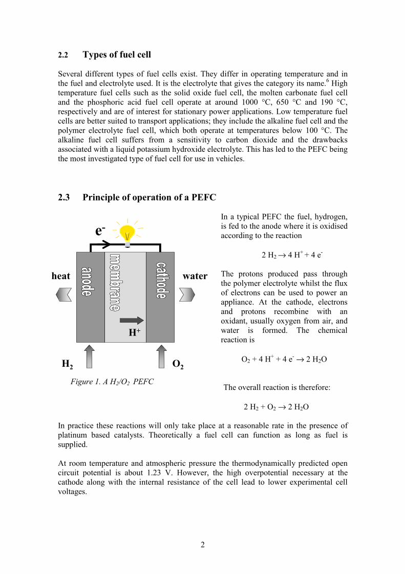
2.3 Principle of operation of a PEFC
In a typical PEFC the fuel, hydrogen, is fed to the anode where it is oxidised according to the reaction
2 H2 → 4 H+ + 4 e-
The protons produced pass through the polymer electrolyte whilst the flux of electrons can be used to power an appliance. At the cathode, electrons and protons recombine with an oxidant, usually oxygen from air, and water is formed. The chemical reaction is
O2 + 4 H+ + 4 e- → 2 H2O
The overall reaction is therefore:
2 H2 + O2 → 2 H2O In practice these reactions will only take place at a reasonable rate in the presence of platinum based catalysts. Theoretically a fuel cell can function as long as fuel is supplied. At room temperature and atmospheric pressure the thermodynamically predicted open circuit potential is about 1.23 V. However, the high overpotential necessary at the cathode along with the internal resistance of the cell lead to lower experimental cell voltages.
e-
H+
H2 O2
waterheat
Figure 1. A H2/O2 PEFC
3
Despite this, the efficiency of a PEFC can reach 40-50 %, which far surpasses that of a combustion engine, where the limits imposed by the Carnot cycle often reduce the efficiency to less than 20 %.2 2.4 The polymer electrolyte during fuel cell operation. The electrode reactions take place at a three-phase interface: gas, catalyst and electrolyte. For the process to be efficient, the area of this interface must be as large as possible. To achieve this, the catalyst layer is usually impregnated with a solution of a proton-conducting polymer (usually a Nafion solution), and the solvent is then evaporated. In the membrane electrode assembly, this recast polymer electrolyte is then placed in contact with the membrane. In an alternative preparation the catalyst is mixed with the ionomer solution and this mixture is then sprayed onto the membrane. The protons formed at the anode migrate towards the cathode under the influence of the electric field. In the sulfonic acid based polymer electrolytes commonly used, the transport of protons requires water and controlling the humidification of the membrane is one of the most complicated aspects of operating the PEFC. Insufficient water causes a loss of conductivity and can also result in localised heating and failure of the membrane; excess water can cause flooding at the cathode and lead to a slower reaction rate. When the cell is operating, water is supplied by humidification of the reactant gases and by the oxygen reduction reaction at the cathode. Inside the membrane, the water profile is determined by the amount of water accompanying the protons as they migrate from anode to cathode (the electro-osmotic drag), the amount of water produced at cathode, and the extent of back diffusion of water through the membrane as the result of the concentration gradient. Balancing the level of humidification is therefore difficult. In thicker membranes an uneven water profile is often a problem. However, modelling suggests that this can largely be remedied by reducing the thickness to 50 µm or less.7 The care required in the water management of the polymer electrolyte fuel cell is a weakness of the electrolyte currently used. The need for water also imposes an operating temperature restriction, which limits the reaction rates at the electrodes. Hence, a system where the water dependence would be less marked is the subject of some research. This has lead to the investigation of anhydrous proton conducting polymer electrolytes using phosphoric acid,8 imidazole and pyrazole-based proton conducting polymers,9 and even electrolytes where proton transport would proceed within hydrogen bonds fixed to a polymer backbone: a “polymer-bound proton solvent”.10 2.5 Issues remaining Although great improvements in fuel cell design and components have been made in the past 10 years, there remain several problems to overcome if fuel cells are to be a viable commercial alternative to ICEs. A major hurdle is the fuel. PEFCs run best on very pure hydrogen. Hydrogen obtained from hydrocarbons tends to contain small amounts of
4
CO, which have disastrous effects on the efficiency of the anode reaction.6, 7 Moreover, the onboard storage of hydrogen is problematic, whilst alternatives such as the onboard reformation of methanol 6 complicate the system and reduce the efficiency. The simpler Direct Methanol Fuel Cell (DMFC), where methanol is used as a fuel instead of hydrogen, suffers from the poor kinetics of the methanol oxidation reaction at low temperatures and from a high methanol permeation rate through the perfluorinated membranes commonly used.11 Finally, the overall cost of the fuel cell with its platinum based catalysts and expensive membrane is still too high. 3. POLYMER ELECTROLYTE MEMBRANES 3.1 Requirements The requirements for membranes to be used in PEFCs are generally agreed to include the following:
o thin o impermeable to H2 and O2 gases o high protonic conductivity (of the order of 100 mS/cm) o non electronically conducting o mechanically strong o stable in an acid and highly oxidative environment
Currently the membranes most referred to are DuPont’s Nafion materials, which were developed in the 1960s for the chlor-alkali industry. However, many other types of membranes are under investigation.12, 13 3.2 Perfluorinated membranes
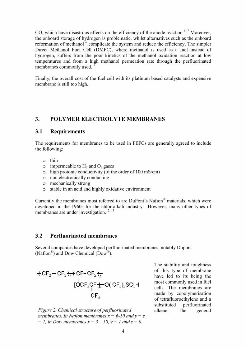
Several companies have developed perfluorinated membranes, notably Dupont (Nafion®) and Dow Chemical (Dow®).
The stability and toughness of this type of membrane have led to its being the most commonly used in fuel cells. The membranes are made by copolymerisation of tetrafluoroethylene and a substituted perfluorinated alkene. The general Figure 2. Chemical structure of perfluorinated
membranes. In Nafion membranes x = 6-10 and y = z = 1, in Dow membranes x = 3 – 10, y = 1 and z = 0.

5
structure is shown in Figure 2. The synthesis of the substituted monomer requires several steps14 and the ultimate cost of the membrane fabrication is high. Perfluorinated membranes differ in the length and structure of the side chain, monomer ratio and thickness. A frequently quoted value is the equivalent weight (EW) of the membrane, which is the molecular weight of one repeat unit in the polymer. As there is one sulfonic acid group per repeat unit, the EW is directly related to the ion-exchange capacity (IEC): IECEW 1=
3.2.1 Structure The structure of perfluorinated membranes has been much investigated and several reviews are available.15, 16 ,17 Investigations of Nafion membranes by Wide Angle X-ray Scattering (WAXS) show that the polymers contain crystalline and amorphous CF2 regions similar to those found in polytetrafluoroethylene (PTFE). A third phase is seen and presumed to contain ionic groups and water.18,19 The crystallites act as physical crosslinks and prevent the polymer from being soluble. A Nafion polymer with an EW of 1200 is 15-20 % crystalline.19 Dow membranes are more crystalline than Nafion, which is explained by the shorter side-chain causing less disruption. The crystallinity increases with increasing EW.20 Dynamic mechanical analysis of Nafion suggests two glass transition temperatures, one assigned to the matrix (140 °C), the other to the ionic clusters (240 °C).21 In calorimetric studies of dry, sodium-exchanged Dow membranes the glass transition temperatures observed are 150-180 °C for the matrix moiety and 270-300 °C for the ionic clusters.20 The precise organisation of the aqueous domains remains a matter of some debate, although all agree that the sulfonic acid groups and water aggregate. Small Angle X-ray Scattering (SAXS) data on Nafion samples suggest, if the ionic aggregates are assumed to be spherical, clusters of 3-5 nm in diameter with a Bragg spacing of 4-5 nm.19 The diameter of the cluster decreases with increasing EW. This has been attributed to the increase in crystallinity and stiffness hindering the hydration and aggregation. In Dow membranes a Bragg spacing of 40-75 Å has been measured.20 Transmission electron micrographs of Nafion stained with a metal support the idea of regular spherical clusters of 3-10 nm in diameter,22,19 although this data must be treated with caution as it has been suggested that the heat of the electron beam could induce some reorganisation.16 Many models have been proposed to describe the structure of perfluorinated ion-exchange membranes.15 The challenge is to reconcile the structural data with the high selectivity observed experimentally. Possibly the simplest model is the three phase model with a fluorocarbon phase, an interfacial region and ionic clusters.23 In this scenario, the majority of the water lies in the third region, whilst the second region contains a small amount of water, sulfonate groups not incorporated in the clusters, and the ether linkages. The selectivity of the membrane is accounted for by large ions residing preferentially in the interfacial region, small or highly charged ions in the ionic clusters. A regular cluster model proposed by Gierke24 fits much of the data fairly satisfactorily and is referred to often. In this model the ionic aggregates take the form of spheres of approximately 40 Å in diameter separated by narrow cylindrical channels with

6
Table I. Mechanical properties of Nafion in the machine and transverse directions (MD and TD respectively) Tensile
modulus MPa
Tensile strength
MPa
Elongation at break %
Tear resistance -initial g/mm
Tear resistance - propagating
g/mm 50 % RH, 23 °C
249 43 MD 32 TD
225 MD 310 TD
6000 MD, TD >100 MD >150 TD
water soaked, 23 °C
114 34 MD 26 TD
200 MD 275 TD
3500 MD, TD 92 MD 104 TD
water soaked, 100 °C
64 25 MD 24 TD
180 MD 240 TD
3000 MD, TD 74 MD 85 TD
diameters of about 10 Å . The narrow channels ensure the high selectivity of the membranes.
3.2.2 Properties The EWs commonly range from 800 to 1500, which corresponds to ion-exchange capacities of 0.6– 1.25 meq/g. Water uptakes are usually 30–55 % (weight percent of the dry membrane).12 The tensile properties of perfluorinated membranes are good, although hydration leads to a significant deterioration: the tensile strength of Nafion 117 drops to less than half its initial value upon hydration.14 Some typical mechanical properties as quoted by Ion Power Inc. are given in Table I.25 Conductivities are of the order of 50–200 mS/cm, depending on the EW and the length of the side-chain.12, 26
3.2.3 Performance Perfluorinated membranes have been tested in fuel cell stacks and for thousands of hours without failing and with reasonable reproducibility.27 Lifetimes of over 50 000 hours for Nafion and over 10 000 hours for Dow membranes have been recorded.12 Currently, the trend is towards lower equivalent weights and thinner membranes. The reduction in thickness not only reduces the cell resistance, but the cost also as less material is used. Thinner membranes, however, have greater gas permeabilities and poorer mechanical properties. 3.3 Other options Research into other types of membranes generally aims at lowering the price and/or improving the performance of the membranes. In general, one of these goals takes
7
precedence. A great number of studies have been published on many types of membrane. A few examples only are described here, and the references are far from exhaustive. Several reviews have appeared.12, 13, 28 Amongst the drawbacks of the current electrolyte is the significant dimensional change on hydration, which causes technical difficulties. To avoid this, membranes such as the Gore Select materials are made of a porous inert substrate, Gore-Tex expanded polytetrafluoroethylene, filled with an ion-exchange polymer (usually Nafion).29 The same approach has been adopted by another company (Johnson Matthey) using a non-woven silica as substrate.30 In both cases the substrate provides dimensional stability. Although the intrinsic resistance of this type of material is higher than that of the perfluorinated membranes, good mechanical properties mean that very thin membranes can be made, so that the potential drop across the membranes is no greater than with homogeneous membranes. Other membranes are specifically designed for use at higher temperatures (around 150 °C). An interesting approach here is the combination of a sulfonated film with a hydrophilic inorganic proton conducting phase, which improves the conductivity, especially above 100 °C. An inorganic phase could also increase the mechanical, chemical and thermal stability. Sulfonated poly(ether ether ketone) and polybenzamidazole combined with inorganic phosphates and oxides have been prepared and characterised.31, 32
The high methanol permeation through perfluorinated membranes is detrimental to the performance of DMFCs. Proposed alternatives include phosphoric acid doped polybenzimidazoles,33 which are less permeable to methanol and can be used at higher temperatures (approaching 200°C), where the methanol oxidation reaction is enhanced. Acid-base blend membranes have also demonstrated promising properties in DMFCs.34 Several groups have investigated the preparation of ion-exchange membranes by sulfonation of pre-formed films. The appeal of this approach lies in its simplicity and low cost. The original polymers can be aliphatic,35 or contain aromatic rings. Radiation has been used to activate partially fluorinated materials towards sulfonation.36 Poly(arylene ether sulfones), polyphenyl quinoxalines, polysulfones, poly(ether ether ketones)32 have all been sulfonated by diverse means.37 A common problem is to achieve sufficient sulfonation for efficient proton conduction without the polymer becoming soluble. The resulting membranes frequently suffer from poor mechanical properties. Ballard has developed trifluorostyrene based membranes known as BAM 3G.38 The polarisation performance is reported to be better than that of Nafion and Dow membranes, and lifetimes are said to exceed 4500 hours.13 3.4 Radiation-grafted membranes Radiation-grafting is a relatively simple way of modifying existing polymers. It is of particular interest in the preparation of ion-exchange membranes because it can be applied to pre-formed polymer films, and thus avoids the problem of processing a sulfonic acid containing polymer. Membranes are commercially available from the Pall Corporation and from Solvay. The possibility of using these materials as fuel cell
8
electrolytes has been investigated by several groups. In general the starting material is a perfluorinated or partially fluorinated film, to which styrene is grafted, sometimes with a crosslinker. The polystyrene grafts are then sulfonated. Poly(tetrafluoroethylene) (PTFE),39 poly(tetrafluoroethylene-co-hexafluoropropylene) (FEP),40 poly(ethylene-alt-tetrafluoroethylene) (ETFE),40 poly(vinylidene fluoride) (PVDF)41, 42 and poly(tetrafluoroethylene-co-perfluorovinylether) (PFA)43 have all been used as host materials for PolyStyrene Sulfonic Acid (PSSA) grafts. Less investigated alternatives to PSSA include grafting glycidyl methacrylate44 and α-methyl styrene45 with subsequent sulfonation. Only the PSSA grafted materials will be discussed here.
3.4.1 Irradiation, grafting and sulfonation. Both radioisotope sources (usually 60Co) and particle accelerators (electron beam and heavy charged particles) have been used to irradiate polymers and bring about ionisation and subsequent graft polymerisation. γ and electron beam (EB) irradiations result in a homogeneous distribution of radiolysis products, whereas heavy charged particles form linear tracks. Although the grafting of PS to PVDF following heavy ion irradiation has been investigated,46 γ and EB irradiation are much more commonly employed to initiate grafting, because of the lower costs involved and the greater ease of use. The substrate can either be exposed alone to the irradiation (pre-irradiation grafting), or along with the monomer to be grafted (simultaneous grafting). Simultaneous grafting is generally used when the dose rate is low (γ source). The pre-irradiation method reduces the likelihood of homopolymer formation. The grafting kinetics have much in common with conventional free radical polymerisation. The main factors influencing the reaction are the absorbed dose, the grafting temperature, the monomer concentration and the diluent. The results are usually given in terms of the amount of PS added to the film or degree of grafting (DOG).
DOGm m
mgrafted initial
initial
=−
× 100%
Grafting proceeds by a reaction front mechanism: grafts form first at the surface, the monomer then diffuses through the grafted part of the membrane and reacts both with the propagating graft chains and with the irradiated polymer.47 At the graft penetration point, the grafting fronts meet and PS is present throughout the thickness of the membrane. The reaction continues until all the chains are terminated and a saturation DOG is reached. Ellinghorst et al. made a series of studies on the effect of the grafting conditions on the DOG and graft distribution in pre-irradiated fluoropolymers.48, 49, 50 They showed that higher absorbed doses result in both a higher initial rate of grafting and a higher saturation degree of grafting. The graft penetration DOG also increased with increasing dose. Higher temperatures enhanced the initial rate of grafting, but led to a lower saturation DOG, which was attributed to the greater chain mobility favouring termination.

9
Crosslinking the PS grafts increases the oxidative stability of the membranes.51 Crosslinkers used include divinyl benzene (DVB), bis(vinyl phenyl) ethane (BVPE), triallyl cyanurate (TAC), or combinations of the above.52, 53 The grafting kinetics and the distribution of the crosslinker in the grafted moiety are then dependent on the reactivities. DVB, which has a higher reactivity than styrene, forms a highly grafted surface and impedes monomer diffusion. This is not observed when the less reactive BVPE is used.52
Chlorosulfonic acid in a chlorinated solvent (dichloro- or tetrachloroethane) at various temperatures is the most common sulfonation agent, and is generally thought to lead to one sulfonic acid group per aromatic ring in the para position. However, other alternatives such as concentrated sulfuric acid have also been used.54 The DVB aromatic ring has been found to be less prone to sulfonation.55
3.4.2 Structural characteristics Much work has been done to characterise radiation-grafted materials. Differential Scanning Calorimetry (DSC) and X-Ray Diffraction (XRD) investigations of the crystallinity of PS grafted FEP56 and PVDF57 have shown that the PS grafts add to the amorphous phase and the crystallinity is affected mainly by dilution. Using the flexible BVPE crosslinker in PVDF-g-PS membranes lessens the drop in the inherent crystallinity, whereas the stiff DVB increases the disruption brought about by grafting.52 Sulfonation of the PVDF-g-PS membranes causes a further drop in the crystallinity, both because of the resulting dilution and because of some destruction of crystallites, the latter being caused by the strain resulting from the aggregation of the sulfonic acid groups.57 On the whole, however, the picture that emerges at relatively low degrees of grafting (<50 %) is one of practically unchanged crystalline portions of PVDF alongside amorphous regions of PVDF to which the PSSA part has been added. Hietala et al. carried out solid state NMR measurements on PVDF-g-PS membranes.58 The proton relaxation times in the rotating frame, T1ρH, confirm that PVDF and PS are phase separated on a nanometer scale. 2-D WISE spectra show that the PVDF chains remain fairly mobile after grafting. The data are consistent with PS domains of sizes of the order of several nanometers.
3.4.3 Properties The IEC of radiation-grafted membranes is largely determined by the DOG, and this in turn depends on the irradiation and grafting conditions. Thus there are no absolute limits or range. The mechanical properties of the ultimate membrane depend on the water content, which is mostly determined by the IEC. At very high DOG, the considerable swelling in water lessens the mechanical strength and the membrane is of little practical use. In crosslinked membranes, the crosslinker used has a significant effect on the mechanical properties: using DVB considerably reduces the mechanical properties, whereas the effect of BVPE is much less marked.52
10
Studies on the water in PVDF-g-PSSA membranes have shown that the water sorption is determined not only by the ion-exchange capacity and counter-ion, but also by the pretreatment of the samples.59 The total water uptake per ionic site in both PVDF-g-PSSA60 and FEP-g-PSSA61 membranes increases with increasing DOG, which is attributed to a cumulative effect of the increase in hydrophilicity and decrease in crystallinity. In both types of membranes, an evaluation of the state of water revealed the presence of three types of water: non-freezing water tightly bound to the ionic sites, bound freezing water and freezing free water.60, 61 The thermal stability of PSSA grafted membranes has been measured by combining thermal gravimetric analysis with mass spectrometry and either thermochromatography (PVDF-g-PSSA) or FTIR (FEP-g-PSSA). In PVDF-g-PSSA the mass loss up to 180 °C is due only to the dehydration of the membrane. Degradation of the sulfonic acid groups takes place from 220 to 320 °C in both inert and oxidative environments. In the sulfonated materials, the PS degrades at 390 °C (270 °C in an oxidative environment). The PVDF is stable up to 410 °C. Crosslinking with DVB and BVPE was found to decrease the thermal stability of the PVDF based materials.62 FEP-g-PSSA materials follow a similar degradation pattern, although the reported onset temperature is considerably higher. Desulfonation starts around 325 °C in uncrosslinked membranes, 310 °C in DVB crosslinked materials.63 In an investigation of the thermal stability of PFA-g-PSSA membranes, samples were placed in an oven under a nitrogen atmosphere at various temperatures.64 The IEC was subsequently measured and plotted as a function of the oven temperature. In these conditions, the IEC remains constant up to 200 °C, but drops dramatically thereafter, which suggests desulfonation. In all cases the thermal stability measured in this way is more than sufficient for low temperature fuel cell applications. However, no long term testing of the stability at a given temperature has been carried out.
3.4.4 Electrochemical data Gas permeabilities of polymer electrolyte membranes are of great importance as any gas crossover inside the fuel cell results in a loss of efficiency. The permeation behaviour of He and H2 through PVDF-g-PSSA membranes has been investigated with a mass spectrometric leak detector,65 and an electrochemical monitoring technique has been employed to determine the O2 and H2 permeability.66 The mass spectrometry measurements show that the H2 permeability of membranes increases tenfold when the membranes are taken from the dry to the water saturated state. The diffusion of H2 in the water is therefore deemed to be the main factor, and crosslinking has little effect other than that associated with the reduction of the water uptake. The gas transmission rate is similar to that of Nafion 117. The electrochemical measurements with H2 do not show a marked dependence of the permeability on the DOG or therefore on the water content. The oxygen permeability of PVDF-g-PSSA determined electrochemically is similar to that measured in Nafion 117, even though the diffusion coefficient and solubility are quite different. The use of BVPE as a crosslinker does not have a significant effect. High conductivities can be achieved with these membranes. For a given material, the conductivity increases with increasing IEC and water uptake. In PVDF-g-PSSA

11
membranes conductivities of over 100 mS/cm have been measured at room temperature for samples of very high DOG.67 A jump in the conductivity values of several orders of magnitude occurs at graft penetration, when polystyrene and, after sulfonation, sulfonic acids are present throughout the thickness of the membrane. This obviously allows channels for proton conduction to form. The use of BVPE or DVB as crosslinkers pushes up the graft penetration DOG, and the conductivity data reflects the difference. Above the graft penetration DOG the use of crosslinkers reduces the conductivity, reflecting the lower water uptake of these membranes.66 Scherer’s group have reported conductivities measured in situ during fuel cell operation at 60 °C of 60 – 110 mS/cm for FEP-g-PSSA and ETFE-g-PSSA. In the same conditions the value for Nafion 117 was 105 mS/cm.40 Commercial Pall RAI low density polyethylene (LDPE), PTFE and FEP-g- PSSA radiation-grafted membranes had in situ conductivities of 30 – 90 mS/cm at 50 °C compared with 80 mS/cm for Nafion 117.68 It is clear that the conductivity of this type of material is comparable to that of the perfluorinated membranes. Fuel cell tests have been carried out by Wang and Capuano with the commercial Pall RAI membranes in a single cell with a 5 cm² active area.68 They achieved good membrane /electrode bonding and repeatable performances by hot pressing the samples to Nafion coated electrodes. The thickness of the radiation-grafted materials was much less than that of Nafion 117 and the open circuit voltages were lower. The polarisation behaviour of the LDPE based membrane was poor, but the other membranes performed better than Nafion 117, because of their lesser thickness. During long term stability tests of up to 1000 hours at 50 °C some degradation occurred, but the rate was slow. However, when the contact between electrodes and membrane was poor or when the membrane was subjected to open circuit conditions for short periods of time, the degradation was much faster. PVDF-g-PSSA membranes have been tested in a small single cell with 5 cm² active area.42 Here the membranes were simply clamped between Nafion coated catalysed commercial electrodes with low Pt loadings. Nafion 117 was used as a reference material. The contact between the radiation-grafted materials and the electrodes was poor and the performance was inferior to that of Nafion 117. Lifetimes at 50 °C were of only a few hundred hours. The brittle DVB crosslinked membranes failed after a few hours operation because changes in the humidification in the cell caused dimensional variations and fractures formed. Poor contact and performance were also seen in fuel cell tests carried out in another study where PVDF-g-PSSA membranes were hot pressed to PSSA impregnated electrodes.54 In experiments carried out by Scherer's group, FEP-g-PSSA membranes clamped to uncoated electrodes also displayed a poor polarisation behaviour and short lifetimes at 60 °C, although the longevity increased to around 1000 hours when DVB was used as a crosslinker.69 OCPs were lower than that observed with Nafion 117. The difference was attributed to gas crossover depolarising the opposite electrode. Crosslinking with a combination of DVB and TAC improved the membranes dramatically and lifetimes in assemblies with Nafion impregnated electrodes at 60 °C reached 6000 hrs.40

12
3.4.5 Degradation The fuel cell tests described above reveal that short lifetimes are likely to be the major weakness of radiation-grafted membranes. The degradation has been attributed to a loss of PSSA brought about by oxygen diffusion through the membrane and subsequent formation of peroxyl radicals at the anode.53 These radicals then attack the tertiary hydrogen in the polystyrene.45 Raman investigations of PVDF-g-PSSA membranes tested in a single cell confirm the loss of most of the PSSA grafts.70 Various research groups have tried to gauge the resistance of different membranes to an oxidising environment by immersing the membrane in hydrogen peroxide solutions,51, 68, 71, 72 although it is unclear how well this replicates the behaviour in a fuel cell. These tests have shown that the membranes stability is improved by crosslinking,51 and that temperature has an important effect.72
3.4.6 Remaining questions The numerous characterisation studies of radiation-grafted membranes have shown that this type of material possesses interesting properties for electrochemical applications, in particular proton conductivities and gas permeabilities that are as good as those of the Nafion materials. The major weakness appears to be the short lifetimes in a fuel cell. Whilst this has been shown to be due to degradation of the PSSA grafts, the lifetimes reported vary significantly. It is obvious that crosslinking improves the stability, but the influence of other factors such as the type of membrane electrode assembly, the mechanical properties of the membrane and the water uptake is less clear. The different groups working on radiation-grafted materials have generally adopted one initial fluoropolymer and studied the membrane properties as a function of the DOG. This has led to a certain amount of repetition of experiments with a different starting material. However, because each group also adopts slightly different grafting and sulfonation conditions, it is very difficult to compare results, to determine what is significant in new studies or to draw any of the conclusions necessary to improve the current membranes. Hence this work tries to determine the influence of the conditions used in the grafting and sulfonation reactions and the changes brought about by the selection of a different initial fluoropolymer.

13
4. EXPERIMENTAL Detailed experimental sections can be found in the original papers and only the main features will be given here. 4.1 Materials
Figure 3. Initial materials used. The chemical structures of the initial fluoropolymers used are shown in Figure 3. They were obtained as 15 – 80 µm thick films from various sources (see III for details). Fluoropolymers were chosen because of their superior thermal and oxidative stability. All other chemicals were reagent grade and used as received. 4.2 Irradiation, grafting and sulfonation The irradiation and grafting of samples are described in papers I and III. Samples were irradiated at room temperature under N2 with an acceleration voltage of 175 kV and the absorbed dose, as estimated from a calibration curve for the apparatus, varied from 5-100 kGy. No difference in properties or grafting kinetics was seen between 80µm samples irradiated from both sides or from one side. Irradiated films were immediately immersed in grafting solutions. After grafting, the films were Soxhlet-extracted with chloroform to remove any homopolymer formed, dried to constant mass and the degree of grafting was determined. Sulfonation was carried out in a closed system of chlorosulfonic acid in dichloroethane. The grafted films were pre-swollen in dichloroethane. After sulfonation, samples were
PVFH
H
H
Fn
PVDFH F
H Fn
ETFE H H
H H
F
F
F
Fn
F
F
H
H
F
F
CF3
Fn
m
PVDF-co-HFP
F
F
CF3
F
F
F
F
Fn
m
FEP
F
F
F
Fn
PTFE

14
soaked for several hours in ethanol and then treated with an acid solution (either hydrochloric or sulfuric acid), followed by boiling in distilled water for at least one hour. 4.3 Characterisation There is no standard way of determining the dry weight of membranes containing sulfonic acids. Investigations of various methods with Nafion 117 suggest different results and some remnant water.73, 74 Here the dry weight was always determined after drying the samples to constant mass at room temperature in a desiccator over P2O5. This is thought to result in complete dehydration. Although it is claimed that the water uptake of Nafion 117 after this drying method is the same irrespective of the rehydration temperature,74 preliminary experiments in our laboratory did not find this to be the case. Samples were therefore boiled in water for at least an hour, and then left to equilibrate at room temperature for water uptake measurements. The ion-exchange capacity was determined by immersing samples in a known volume of sodium hydroxide, and titrating the excess sodium hydroxide with hydrochloric acid using a cresol red indicator the following day. Other analyses carried out included tensile testing, I, IV examination of the surface topography by atomic force microscopyIII and SEMI, determination of the fluorine and sulfur distributions in the cross-section,I, II gravimetric determination of water sorption from the vapour phase,IV NMR measurements of the relaxation times and water self diffusion coefficient,IV DSC measurements of the crystallinityIII and XRD and DSC investigations of the state of water in the membranes.IV, VI The electrochemical characterisation involved conductivity measurements using impedance spectroscopy II, III, IV, V, VI, gas permeabilities measured chronoamperometrically using a microelectrode cellV and fuel cell tests.V

15
5. RESULTS AND DISCUSSIONS 5.1 Irradiation and grafting
5.1.1 Grafting kinetics in propanol The degree of grafting of styrene in PVDF was studied as a function of the absorbed dose, monomer concentration and temperature in styrene propanol systems.I The results are qualitatively similar to those observed in comparable systems49, 75 and described in section 3.4.1. The reaction always follows the same pattern: the DOG increases rapidly initially whilst propagation is the main reaction, then more slowly as termination becomes more frequent. Very high DOGs of well over 100 % can be reached. The order of dependence of the initial grafting rate was 0.43 on the absorbed dose and 1.2 on monomer concentration. These values are fairly close to the 0.5 and 1 expected in conventional free radical polymerisation. The slightly lower dependence on the dose could be attributed to some recombination of primary radicals: irradiation and grafting were carried out at temperatures well above the glass transition temperature of PVDF (-40 °C76). The higher dependence on the monomer concentration could be attributable to the high viscosity of the grafted zone, which impedes termination and monomer diffusion. The data yield an activation energy of 73 kJ/mol.
5.1.2 Influence of the diluent on the grafting kinetics
0
50
100
150
0 1 2 3 4 5grafting time (h)
Figure 4. DOG as a function of time in styrene (•), 50 % styrene in propanol (∆) and 50 % styrene in toluene (□) (vol. %). 100 kGy absorbed dose, 70 °C reaction temperature. 80 µm PVDF.

16
Comparatively little attention has been paid to the influence of the diluent used in the grafting reaction. The prevailing view is that, for the grafting to be efficient, it is necessary to use a diluent that swells the PS grafts and thereby facilitates the penetration of monomer.77 Figure 4 shows that in pre-irradiation grafting this is not the case. Both the initial rate of grafting and the saturation DOG are higher in styrene/propanol than in styrene/toluene solutions. Neither the diluents nor the styrene swell the PVDF film significantly, but styrene and toluene swell the PS grafts, whereas propanol does not. The overall styrene uptake of a highly grafted film is approximately the same in both a styrene/toluene and a styrene/propanol solution.I This suggests an explanation for the difference in the grafting kinetics: toluene could be present along with styrene in the grafted zone, which would diminish the monomer concentration and lower the initial grafting rate. In styrene/propanol solutions, however, styrene would diffuse alone into the grafted region. The higher saturation DOG in propanol can be explained by the higher viscosity of the grafts in contact with the non solvent, which impedes termination. Some subsequent grafting experiments were carried out with a solvent that swells the matrix material. The initial PVDF film is soluble in DMF at 70 °C and when grafting is carried out in a 50 % DMF solution the film disintegrates. However, in 20 % DMF the film retains its shape and the grafting is completed in a very short time (cf. Figure 5). The saturation DOG is approached in about 30 min and is relatively low. Acetone, which also swells the PVDF film, has a similar effect. The swelling of the matrix obviously facilitates monomer diffusion, but the reduced viscosity favours termination.
5.1.3 Properties of PS grafted PVDF The grafted films were examined with SEM and a combined energy-dispersive x-ray spectrometer.I The data show that at a similar DOG the distribution of the PS grafts is
0
20
40
60
80
100
0 10 20 30 40 50 60 70time (min)
DO
G (%
)
Figure 5. DOG as a function of time in 80 % styrene / 20 % propanol (♦) and 80 % styrene / 20%DMF (o) at 70 °C. 100 kGy absorbed dose. 40 µm PVDF.

17
different in the samples prepared with different diluents: graft penetration occurs at a lower DOG in styrene/toluene than in styrene/propanol solutions. When the grafting solutions contain acetone or DMF, the concentration of PS tends to be higher in the core of the film than on the surface. This type of distribution is detrimental to the conductivity of the ultimate membrane as isolating surface layers are created Examinations of the surface of the grafted films by SEM show another effect of the diluent: films grafted in toluene have relatively smooth surfaces, whilst using propanol leads to cavities of up to 10 µm in diameter (Figure 6). Films grafted in styrene possess surfaces of intermediate appearance. The difference reflects the solvation properties of toluene and propanol. The choice of diluent also has an effect on the tensile properties of the grafted films. Table II gives the values obtained in the direction of orientation of the film. The tensile strength does not change significantly, but the elongation at break differs considerably according to the grafting solution used. Irradiation diminishes the extent to which the film elongates, and grafting always brings about a further drop. The extent of the deterioration, however, varies considerably: the elongation at break of films grafted in toluene is over ten times that of films grafted in propanol. Grafting in pure styrene produces films with intermediate properties. In samples grafted in styrene/propanol solutions, the tensile properties are not dependent on the DOG. One explanation for these differences in behaviour is that the heightened rate of grafting in propanol leads to the formation of larger PS domains, which disrupt the amorphous PVDF more, causing the drop in the elongation at break. The rougher surface could also be more favourable to the rupture without elongation.
Figure 6. SEM image of a surface cavity in PVDF-g-PS grafted in a styrene/propanol solution.
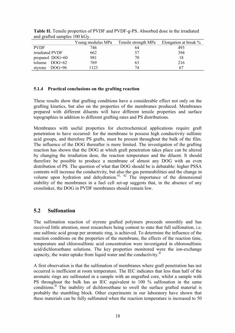
18
Table II. Tensile properties of PVDF and PVDF-g-PS. Absorbed dose in the irradiated and grafted samples 100 kGy. Young modulus MPa Tensile strength MPa Elongation at break % PVDF 746 64 493 irradiated PVDF 662 57 394 propanol DOG=60 981 70 18 toluene DOG=62 769 63 216 styrene DOG=96 1123 74 67
5.1.4 Practical conclusions on the grafting reaction These results show that grafting conditions have a considerable effect not only on the grafting kinetics, but also on the properties of the membranes produced. Membranes prepared with different diluents will have different tensile properties and surface topographies in addition to different grafting rates and PS distributions. Membranes with useful properties for electrochemical applications require graft penetration to have occurred: for the membrane to possess high conductivity sulfonic acid groups, and therefore PS grafts, must be present throughout the bulk of the film. The influence of the DOG thereafter is more limited. The investigation of the grafting reaction has shown that the DOG at which graft penetration takes place can be altered by changing the irradiation dose, the reaction temperature and the diluent. It should therefore be possible to produce a membrane of almost any DOG with an even distribution of PS. The question of what that DOG should be is debatable: higher PSSA contents will increase the conductivity, but also the gas permeabilities and the change in volume upon hydration and dehydration.41, 42 The importance of the dimensional stability of the membranes in a fuel cell set-up suggests that, in the absence of any crosslinker, the DOG in PVDF membranes should remain low. 5.2 Sulfonation The sulfonation reaction of styrene grafted polymers proceeds smoothly and has received little attention, most researchers being content to state that full sulfonation, i.e. one sulfonic acid group per aromatic ring, is achieved. To determine the influence of the reaction conditions on the properties of the membrane, the effects of the reaction time, temperature and chlorosulfonic acid concentration were investigated in chlorosulfonic acid/dichloroethane solutions. The key properties monitored were the ion-exchange capacity, the water uptake from liquid water and the conductivity.II A first observation is that the sulfonation of membranes where graft penetration has not occurred is inefficient at room temperature. The IEC indicates that less than half of the aromatic rings are sulfonated in a sample with an ungrafted core, whilst a sample with PS throughout the bulk has an IEC equivalent to 100 % sulfonation in the same conditions.II The inability of dichloroethane to swell the surface grafted material is probably the stumbling block. Other experiments in our laboratory have shown that these materials can be fully sulfonated when the reaction temperature is increased to 50

19
°C. The water uptake and proton conductivity of the partially sulfonated surface-grafted material are very low. Investigations of samples possessing an even PS profile throughout the bulk of the film reveal that the sulfonation reaction proceeds by a reaction front mechanism, with grafts on the surface sulfonating first. Extending the reaction time increases the level of sulfonation and the IEC. The water uptake and conductivity change abruptly when the sulfonation reaches the centre of the membrane. Extending the reaction time beyond the time needed to reach full sulfonation does not seem to have any effect. Increasing the concentrations of chlorosulfonic acid diminishes the time necessary for full sulfonation. However, at high concentrations the IEC, water uptake and conductivity decrease with increasing concentration (Figure 7). The samples also become more fragile. The change in the properties when higher concentrations are used suggests an increase in side-reactions, which could affect either the PVDF moiety or the PS. The colour of sulfonated films varies from pale yellow to brown according to the concentration of the sulfonation solution. The original PVDF film does not react when placed in these solutions. However, subsequent experiments have shown that the colour depends on the initial material, which suggests that PVDF is indeed reacting to a certain extent.III The colour changes were more marked in less fluorinated materials, suggesting that double bonds form. The drop in IEC cannot, however, be attributed to this side-reaction.
0
1
2
3
0.0 0.1 1.0 10.0
[ClSO3H] (mol/L)
0
50
100
150σ
Figure 7. Ion-exchange capacity (�), water uptake (�) and conductivity (▲) versus the concentration of chlorosulfonic acid in dichloroethane. Samples sulfonated for 24 hours at room temperature.
20
-0.05
0.05
0.15
0.25
0.35
0.45
0.55
0.000 0.500 1.000 1.500 2.000 2.500 3.000 3.500
[ClSO3H]0 (mol/l)
(IEC
MAS
S IN
CR
EASE
- IE
CTI
TRAT
ION)
IEC
DO
G
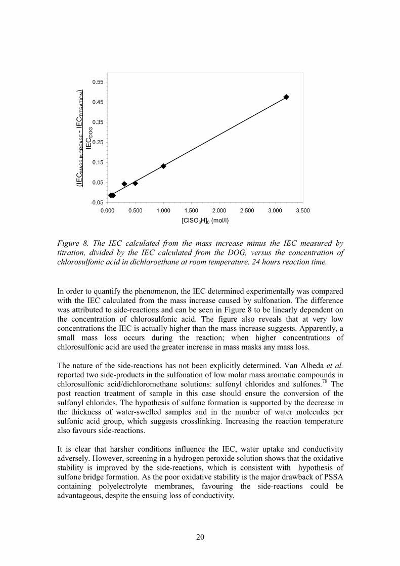
Figure 8. The IEC calculated from the mass increase minus the IEC measured by titration, divided by the IEC calculated from the DOG, versus the concentration of chlorosulfonic acid in dichloroethane at room temperature. 24 hours reaction time. In order to quantify the phenomenon, the IEC determined experimentally was compared with the IEC calculated from the mass increase caused by sulfonation. The difference was attributed to side-reactions and can be seen in Figure 8 to be linearly dependent on the concentration of chlorosulfonic acid. The figure also reveals that at very low concentrations the IEC is actually higher than the mass increase suggests. Apparently, a small mass loss occurs during the reaction; when higher concentrations of chlorosulfonic acid are used the greater increase in mass masks any mass loss. The nature of the side-reactions has not been explicitly determined. Van Albeda et al. reported two side-products in the sulfonation of low molar mass aromatic compounds in chlorosulfonic acid/dichloromethane solutions: sulfonyl chlorides and sulfones.78 The post reaction treatment of sample in this case should ensure the conversion of the sulfonyl chlorides. The hypothesis of sulfone formation is supported by the decrease in the thickness of water-swelled samples and in the number of water molecules per sulfonic acid group, which suggests crosslinking. Increasing the reaction temperature also favours side-reactions. It is clear that harsher conditions influence the IEC, water uptake and conductivity adversely. However, screening in a hydrogen peroxide solution shows that the oxidative stability is improved by the side-reactions, which is consistent with hypothesis of sulfone bridge formation. As the poor oxidative stability is the major drawback of PSSA containing polyelectrolyte membranes, favouring the side-reactions could be advantageous, despite the ensuing loss of conductivity.
21
5.3 Influence of the initial matrix polymer The investigations of the grafting and sulfonation reactions have shown that the reaction conditions used during the membrane preparation have a significant effect on the properties. Samples of similar DOG based on the same fluoropolymer can have vastly different water uptakes. conductivities and mechanical properties. A direct consequence of this is that comparing the different fluoropolymer-g-PSSA membranes prepared by various research groups is very difficult. It is impossible to know whether the differences in behaviour are attributable to the preparation route followed or to the change in the initial matrix. To resolve this question and to determine the real influence of the starting material a series of fluoropolymers with similar PSSA contents were prepared in similar conditions.
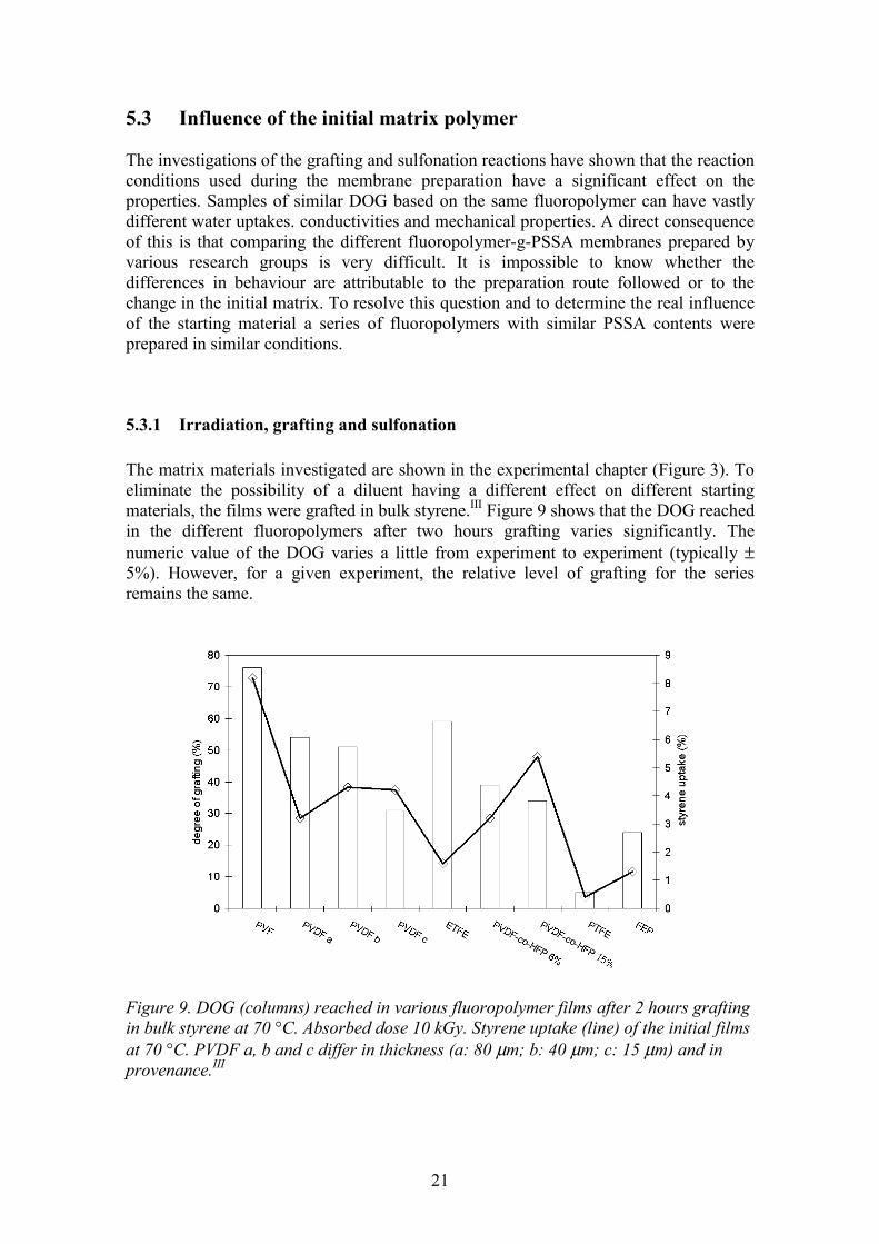
5.3.1 Irradiation, grafting and sulfonation The matrix materials investigated are shown in the experimental chapter (Figure 3). To eliminate the possibility of a diluent having a different effect on different starting materials, the films were grafted in bulk styrene.III Figure 9 shows that the DOG reached in the different fluoropolymers after two hours grafting varies significantly. The numeric value of the DOG varies a little from experiment to experiment (typically ± 5%). However, for a given experiment, the relative level of grafting for the series remains the same.
Figure 9. DOG (columns) reached in various fluoropolymer films after 2 hours grafting in bulk styrene at 70 °C. Absorbed dose 10 kGy. Styrene uptake (line) of the initial films at 70 °C. PVDF a, b and c differ in thickness (a: 80 µm; b: 40 µm; c: 15 µm) and in provenance.III
22
The differences are attributable to differences in the radical concentration and lifetime following irradiation, in the styrene uptake, and in the rate of termination of the grafts. This means that the chemical structure, the crystallinity of the initial film (Table 3) and the mobility of the polymer chains at the irradiation and grafting temperatures all influence the grafting reaction at several stages. The determining factor is, therefore, difficult to pin-point. For example, radicals in amorphous regions above the Tg are more accessible, but have shorter lifetimes than radicals in crystalline regions. Moreover, because of the chain mobility, the termination rate in the grafting reaction is higher in the more amorphous polymers. A lower crystallinity therefore usually results in a lower DOG. From a practical point of view, in order to obtain membranes with similar DOG and even PS content, a parameter has to be changed. Varying the absorbed dose proved effective and a series of membranes were prepared with 30 %< DOG < 40 % and even PS profiles. Sulfonation of the grafted materials was carried out in 0.2 mol/l chlorosulfonic acid in dichloroethane at room temperature for 24 hours. After sulfonation the membranes varied in colour, but all save PVF had IECs corresponding to over 75 % sulfonation. Two of the initial films were dropped: the grafting of PS to the PTFE film was abandoned as the process was very inefficient. The PVF material was abandoned as it became black and very brittle when sulfonated; the PVF itself obviously reacts to a significant extent.
5.3.2 Structure and water uptake
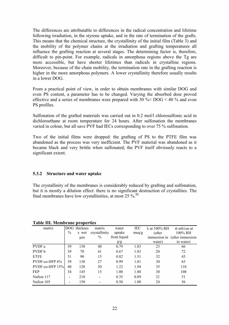
The crystallinity of the membranes is considerably reduced by grafting and sulfonation, but it is mostly a dilution effect: there is no significant destruction of crystallites. The final membranes have low crystallinities, at most 25 %.III
Table III. Membrane properties
matrix
DOG %
thickness wet µm
matrix crystallinity
%
water uptake
from liquid g/g
IEC meq/g
λ at 100% RH (after
immersion in water)
σ mS/cm at 100% RH
(after immersion in water)
PVDF a 39 130 40 0.79 1.83 23 66 PVDF b 39 70 41 0.67 1.83 20 72 ETFE 31 90 15 0.82 1.51 32 43 PVDF-co-HFP 6% 39 130 27 0.99 1.81 30 63 PVDF-co-HFP 15% 40 120 20 1.22 1.94 35 110 FEP 34 145 15 1.00 1.80 30 108 Nafion 117 - 210 - 0.35 0.89 21 51 Nafion 105 - 150 - 0.50 1.00 24 56
23
5
10
15
20
25
30
35
0 5 10 15 20 25 30
crystallinity (%)
λ
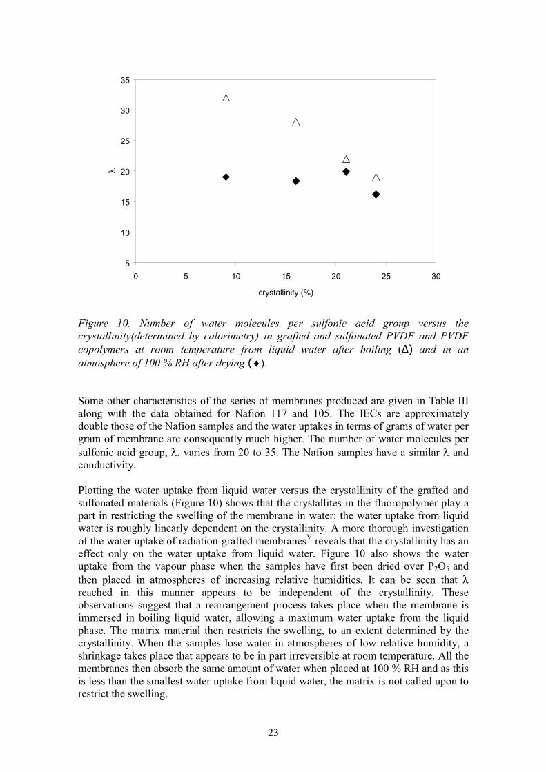
Figure 10. Number of water molecules per sulfonic acid group versus the crystallinity(determined by calorimetry) in grafted and sulfonated PVDF and PVDF copolymers at room temperature from liquid water after boiling (∆) and in an atmosphere of 100 % RH after drying (♦). Some other characteristics of the series of membranes produced are given in Table III along with the data obtained for Nafion 117 and 105. The IECs are approximately double those of the Nafion samples and the water uptakes in terms of grams of water per gram of membrane are consequently much higher. The number of water molecules per sulfonic acid group, λ, varies from 20 to 35. The Nafion samples have a similar λ and conductivity. Plotting the water uptake from liquid water versus the crystallinity of the grafted and sulfonated materials (Figure 10) shows that the crystallites in the fluoropolymer play a part in restricting the swelling of the membrane in water: the water uptake from liquid water is roughly linearly dependent on the crystallinity. A more thorough investigation of the water uptake of radiation-grafted membranesV reveals that the crystallinity has an effect only on the water uptake from liquid water. Figure 10 also shows the water uptake from the vapour phase when the samples have first been dried over P2O5 and then placed in atmospheres of increasing relative humidities. It can be seen that λ reached in this manner appears to be independent of the crystallinity. These observations suggest that a rearrangement process takes place when the membrane is immersed in boiling liquid water, allowing a maximum water uptake from the liquid phase. The matrix material then restricts the swelling, to an extent determined by the crystallinity. When the samples lose water in atmospheres of low relative humidity, a shrinkage takes place that appears to be in part irreversible at room temperature. All the membranes then absorb the same amount of water when placed at 100 % RH and as this is less than the smallest water uptake from liquid water, the matrix is not called upon to restrict the swelling.
24
-40 -35 -30 -25 -20 -15 -10 -5 0temperature (°C)
endo
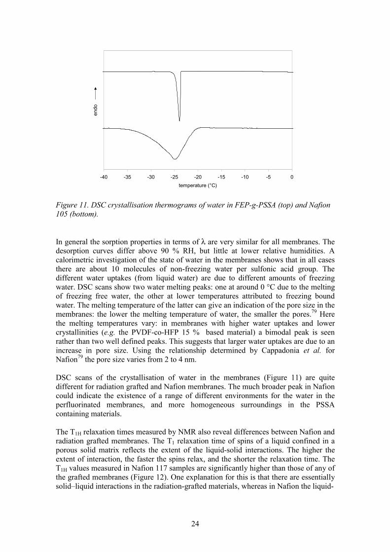
Figure 11. DSC crystallisation thermograms of water in FEP-g-PSSA (top) and Nafion 105 (bottom). In general the sorption properties in terms of λ are very similar for all membranes. The desorption curves differ above 90 % RH, but little at lower relative humidities. A calorimetric investigation of the state of water in the membranes shows that in all cases there are about 10 molecules of non-freezing water per sulfonic acid group. The different water uptakes (from liquid water) are due to different amounts of freezing water. DSC scans show two water melting peaks: one at around 0 °C due to the melting of freezing free water, the other at lower temperatures attributed to freezing bound water. The melting temperature of the latter can give an indication of the pore size in the membranes: the lower the melting temperature of water, the smaller the pores.79 Here the melting temperatures vary: in membranes with higher water uptakes and lower crystallinities (e.g. the PVDF-co-HFP 15 % based material) a bimodal peak is seen rather than two well defined peaks. This suggests that larger water uptakes are due to an increase in pore size. Using the relationship determined by Cappadonia et al. for Nafion79 the pore size varies from 2 to 4 nm. DSC scans of the crystallisation of water in the membranes (Figure 11) are quite different for radiation grafted and Nafion membranes. The much broader peak in Nafion could indicate the existence of a range of different environments for the water in the perfluorinated membranes, and more homogeneous surroundings in the PSSA containing materials. The T1H relaxation times measured by NMR also reveal differences between Nafion and radiation grafted membranes. The T1 relaxation time of spins of a liquid confined in a porous solid matrix reflects the extent of the liquid-solid interactions. The higher the extent of interaction, the faster the spins relax, and the shorter the relaxation time. The T1H values measured in Nafion 117 samples are significantly higher than those of any of the grafted membranes (Figure 12). One explanation for this is that there are essentially solid–liquid interactions in the radiation-grafted materials, whereas in Nafion the liquid-

25
0
50
100
150
200
250
300
350
400
450
0 5 10 15 20 25 30 35 40 45λ
T 1 (
ms)
Figure 12. T1H relaxation times in Nafion 117 (♦) and radiation-grafted membranes based on different fluoropolymer films. (Ο).
liquid interactions are also numerous. A morphology compatible with this would have large water clusters in Nafion and more homogeneous domains in the PSSA grafted membranes. The increase in T1 at higher λ in Nafion would then be due an increase in the cluster size and a greater number of liquid-liquid interactions. Pulsed field gradient NMR diffusion measurements were carried out to determine the water self-diffusion coefficient.IV All the membranes have broadly similar diffusion coefficients at similar λ. Hietala et al. measured the diffusion coefficients in PVDF-g-PSSA membranes with different PSSA contents and found that the DOG, and therefore the IEC and/or water uptake in terms of grams of water per gram of membrane, is an important factor.59 This suggests that Nafion is behaving differently from the radiation grafted membranes: the water self-diffusion coefficient is higher than that of water in the radiation-grafted material of similar water uptake (in g/g) would be.
The conductivity of this series of membranes at 100 % RH reflects the water uptake. However, at intermediate RH and similar λ conductivities are higher in Nafion than in the radiation grafted membranes. In Figure 13 both the proton diffusion coefficient (calculated from the conductivity data) and the water self-diffusion coefficient (obtained from NMR data) are shown as a function of λ. The proton diffusion coefficient drops faster than the water self diffusion coefficient in the PSSA containing materials but not in Nafion. Two factors could contribute to this: as the water content drops some hydrophilic domains in the less mobile PSSA may become isolated and cut off from the conduction paths. Another possible contributing factor is that the slightly weaker nature of the acid in PSSA leads to stronger interactions between the protons and sulfonate groups and therefore a lower proton diffusion coefficient.

26
0.01
0.1
1
10
100
0 5 10 15 20 25 30 35
λ
D *1
E6
(cm
²/s)
Figure 13. Water self-diffusion coefficient as a function of λ in Nafion 117 (♦) and FEP-g-PSSA (•); proton diffusion coefficient in Nafion 117 (�) and FEP-g-PSSA (O).
5.3.3 Other properties Tensile testing shows that, although the properties of the initial fluoropolymer films vary widely, once the materials have been grafted and sulfonated the Young modulus (Figure 14) and the tensile strength in the partially dried state are much the same. The elongation at break varies more (Figure 15), but the reasons for the differences are unclear.
0
200
400
600
800
1000
1200
PVF PVDF a PVDF b PVDF c PVDF-co-HFP
6%
PVDF-co-HFP
15%
ETFE PTFE FEP Nafion105
Figure 14. Young modulus of the original films (white columns) and of the grafted and sulfonated membranes (shaded columns) at 50 % RH and room temperature.

27
0
200
400
600
800
PVF PVDF a PVDF b PVDF c PVDF-co-HFP
6%
PVDF-co-HFP
15%
ETFE PTFE FEP Nafion105
Figure 15. Elongation at break of the original films (white columns) and of the grafted and sulfonated membranes (shaded columns) at 50 % RH and room temperature. At this relative humidity the samples all contain approximately the same amount of water;IV at higher RH the differences in the absolute water uptake would undoubtedly play an important part in determining the tensile properties. The matrix, however, does not appear to have a significant influence on the inherent mechanical properties of the grafted and sulfonated material.
0
20
40
60
80
100
120
0 0.2 0.4 0.6 0.8 1 1.2initial water uptake (g/g)
crosslinked PVDF PVDF
PVDF
ETFE
FEP
PVDF-co-HFP
Figure 16. Remaining mass of PSSA versus water uptake for various fluoropolymer-g-PSSA (♦) after 24 hours immersion in a 3% H2O2 solution containing 20 ppm Fe2+ at room temperature. DVB (10 %) crosslinked PSSA (∆).
28
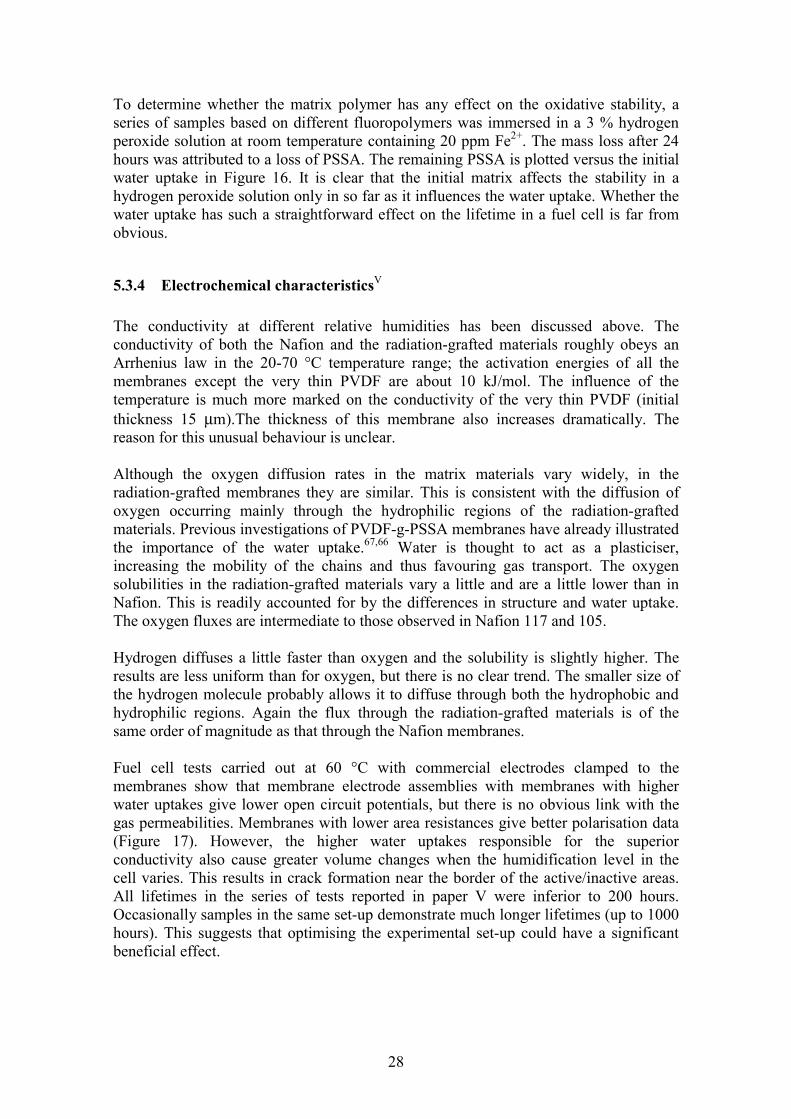
To determine whether the matrix polymer has any effect on the oxidative stability, a series of samples based on different fluoropolymers was immersed in a 3 % hydrogen peroxide solution at room temperature containing 20 ppm Fe2+. The mass loss after 24 hours was attributed to a loss of PSSA. The remaining PSSA is plotted versus the initial water uptake in Figure 16. It is clear that the initial matrix affects the stability in a hydrogen peroxide solution only in so far as it influences the water uptake. Whether the water uptake has such a straightforward effect on the lifetime in a fuel cell is far from obvious.
5.3.4 Electrochemical characteristicsV
The conductivity at different relative humidities has been discussed above. The conductivity of both the Nafion and the radiation-grafted materials roughly obeys an Arrhenius law in the 20-70 °C temperature range; the activation energies of all the membranes except the very thin PVDF are about 10 kJ/mol. The influence of the temperature is much more marked on the conductivity of the very thin PVDF (initial thickness 15 µm).The thickness of this membrane also increases dramatically. The reason for this unusual behaviour is unclear. Although the oxygen diffusion rates in the matrix materials vary widely, in the radiation-grafted membranes they are similar. This is consistent with the diffusion of oxygen occurring mainly through the hydrophilic regions of the radiation-grafted materials. Previous investigations of PVDF-g-PSSA membranes have already illustrated the importance of the water uptake.67,66 Water is thought to act as a plasticiser, increasing the mobility of the chains and thus favouring gas transport. The oxygen solubilities in the radiation-grafted materials vary a little and are a little lower than in Nafion. This is readily accounted for by the differences in structure and water uptake. The oxygen fluxes are intermediate to those observed in Nafion 117 and 105. Hydrogen diffuses a little faster than oxygen and the solubility is slightly higher. The results are less uniform than for oxygen, but there is no clear trend. The smaller size of the hydrogen molecule probably allows it to diffuse through both the hydrophobic and hydrophilic regions. Again the flux through the radiation-grafted materials is of the same order of magnitude as that through the Nafion membranes. Fuel cell tests carried out at 60 °C with commercial electrodes clamped to the membranes show that membrane electrode assemblies with membranes with higher water uptakes give lower open circuit potentials, but there is no obvious link with the gas permeabilities. Membranes with lower area resistances give better polarisation data (Figure 17). However, the higher water uptakes responsible for the superior conductivity also cause greater volume changes when the humidification level in the cell varies. This results in crack formation near the border of the active/inactive areas. All lifetimes in the series of tests reported in paper V were inferior to 200 hours. Occasionally samples in the same set-up demonstrate much longer lifetimes (up to 1000 hours). This suggests that optimising the experimental set-up could have a significant beneficial effect.

29
Figure 17. Polarisation curves at 60 °C and atmospheric pressure of 80 µm PVDF (dashed line), 40 µm PVDF (solid line) and 15µm PVDF (dotted line) based membranes. 5 cm² fuel cell. Cell temperature 60 °C, gas flow rates 1 ml/s. Electrodes:20 % Pt/C; 0.35 mg Pt/cm²; 0.5-0.8 mg/cm² Nafion. The degradation rate is reduced when membranes with a lower DOG (around 25 %) are used in fully humidified cells.80 Figure 18 shows a galvanostatic test with PVDFb-g-PSSA. The initial OCPs in this series of tests are close to 1 V and comparable to those obtained with Nafion. It can be seen that the current remains more or less constant for 300 hours, and then decreases sharply. The OCP at the end of the test is about 885 mV, indicating a small hole in the membrane. The High Frequency (HF) impedance, also shown, gives an indication of the internal resistance of the membrane.
5.3.4 Conclusions on the importance of the matrix material The experiments described above show that most fluoropolymer films can be used as starting materials for radiation-grafted ion-exchange membranes. The grafting conditions need to be modified a little to obtain the same DOG in different materials. The main influence of the matrix is on the water uptake from liquid water, which varies according to the crystallinity of the fluoropolymer. Through its impact on this, when wet membranes are used, the matrix indirectly has an effect on the conductivity, open circuit voltage and lifetime. The mechanical properties of fully humidified membranes and the extent of the dimensional change on hydration would without doubt also reflect the difference in water uptake. However, beyond this role of constraining host to the PSSA grafts, the fluoropolymer does not appear to interact with the proton conducting moiety.

30
Figure 18. Cell voltage versus time. The membrane is based on 40µm PVDF, DOG=25 %.Cell temperature 70 °C, fully humidified gases (flow rates 1 ml/s). Electrodes: 20 % Pt/C; 1 mg/cm² Pt; 0.6-0.8mg/cm² Nafion.80
5.4 Crosslinked membranes
5.4.1 Preparation and characteristics of crosslinked PVDF-g-PSSA Crosslinkers are used in the grafting reaction to improve the oxidative and the mechanical stability. As discussed in the review of previous work on radiation grafted membranes (cf. paragraph 3.4) PVDF-g-PSSA membranes have been crosslinked with both DVB and BVPE. The major drawback with DVB is the increase in the brittleness of the final membrane. BVPE does not have such a dramatic effect on the mechanical properties. However, it is not a commercial product and the synthesis of the monomer is tedious81 especially in larger quantities. Tests on uncrosslinked and crosslinked PVDF-g-PSSA of similar DOG show that the resistance to a hydrogen peroxide solution is improved (Figure 19; this is also seen in Figure 16), although whether this is entirely due to a greater inherent stability or whether the reduction in the water uptake is the more important factor is unclear.
31
0
20
40
60
80
100
no crosslinker 2.5% BVPE 5% BVPE 10% BVPE
Figure 19 Mass percentage of PSSA (white columns) and percentage of IEC (shaded columns) remaining after the hydrogen peroxide test. 10 vol% H2O2, room temperature, 24 hours. All samples have a DOG of approximately 70 %. More flexible DVB crosslinked membranes than those prepared hitherto can be made by using a solvent in the grafting reaction that swells the PVDF. Samples with DOGs of around 20 % were prepared using grafting solutions of styrene, DVB, toluene and DMF. The sulfur profiles show that, after sulfonation, sulfur is present throughout the bulk of these membranes. However, as discussed in section 5.1.3, the surface concentration is lower than the concentration in the interior of the film. A sample with DOG of 22 has an IEC of 1.42 meq/g and a water uptake of 0.25 g/g (λ=10). The mechanical properties are good. The conductivity, however, is less than 1 mS/cm. The low surface concentration of sulfonic acid groups presumably creates a barrier to the migration of the protons. More work is therefore needed to find grafting conditions suitable for the preparation of evenly grafted DVB crosslinked membranes with good mechanical properties.
5.4.2 The state of water in crosslinked PVDF-g-PSSA The state of water was investigated in PVDF-g-PSSA membranes grafted in similar conditions without crosslinker, with 5 % BVPE, and with 5 % DVB (monomer molar ratios).VI Some of the results are collected in Table IV. It is clear that the DOG at graft penetration varies according to the composition of the grafting solution. As discussed above (paragraph 5.2), the sulfonation of surface grafted films is inefficient at room temperature, which results in low IECs and water uptakes. The ungrafted, unsulfonated core of the film also represents an isolating layer that stops the transport of protons and therefore reduces the conductivity dramatically. From Table IV graft penetration can be seen to occur at a lower DOG when no crosslinker used.
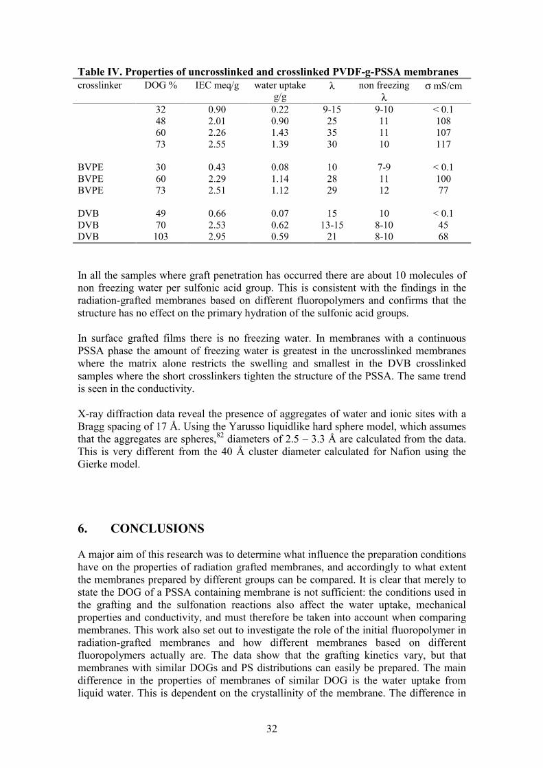
32
Table IV. Properties of uncrosslinked and crosslinked PVDF-g-PSSA membranes crosslinker DOG % IEC meq/g water uptake
g/g λ non freezing
λ σ mS/cm
32 0.90 0.22 9-15 9-10 < 0.1 48 2.01 0.90 25 11 108 60 2.26 1.43 35 11 107 73 2.55 1.39 30 10 117 BVPE 30 0.43 0.08 10 7-9 < 0.1 BVPE 60 2.29 1.14 28 11 100 BVPE 73 2.51 1.12 29 12 77 DVB 49 0.66 0.07 15 10 < 0.1 DVB 70 2.53 0.62 13-15 8-10 45 DVB 103 2.95 0.59 21 8-10 68 In all the samples where graft penetration has occurred there are about 10 molecules of non freezing water per sulfonic acid group. This is consistent with the findings in the radiation-grafted membranes based on different fluoropolymers and confirms that the structure has no effect on the primary hydration of the sulfonic acid groups. In surface grafted films there is no freezing water. In membranes with a continuous PSSA phase the amount of freezing water is greatest in the uncrosslinked membranes where the matrix alone restricts the swelling and smallest in the DVB crosslinked samples where the short crosslinkers tighten the structure of the PSSA. The same trend is seen in the conductivity. X-ray diffraction data reveal the presence of aggregates of water and ionic sites with a Bragg spacing of 17 Å. Using the Yarusso liquidlike hard sphere model, which assumes that the aggregates are spheres,82 diameters of 2.5 – 3.3 Å are calculated from the data. This is very different from the 40 Å cluster diameter calculated for Nafion using the Gierke model. 6. CONCLUSIONS A major aim of this research was to determine what influence the preparation conditions have on the properties of radiation grafted membranes, and accordingly to what extent the membranes prepared by different groups can be compared. It is clear that merely to state the DOG of a PSSA containing membrane is not sufficient: the conditions used in the grafting and the sulfonation reactions also affect the water uptake, mechanical properties and conductivity, and must therefore be taken into account when comparing membranes. This work also set out to investigate the role of the initial fluoropolymer in radiation-grafted membranes and how different membranes based on different fluoropolymers actually are. The data show that the grafting kinetics vary, but that membranes with similar DOGs and PS distributions can easily be prepared. The main difference in the properties of membranes of similar DOG is the water uptake from liquid water. This is dependent on the crystallinity of the membrane. The difference in

33
water uptake in turn affects such properties as the conductivity, mechanical properties in the fully humidified state and the lifetime in a fuel cell. However, the fluoropolymer does not interact with the hydrophilic, proton conducting moiety. Its role is merely one of constraining host. Most of the fluoropolymers tested here are suitable starting materials for fuel cell membranes, although the preparation conditions, ideal DOG and degree of crosslinking would differ. The work presented here has also demonstrated the flexibility of the radiation-grafting process and the advantages of this approach in the preparation of ion-exchange membranes. The irradiation, grafting and sulfonation conditions can easily be changed to obtain membranes of different IECs and properties. The ideal DOG and IEC remain debatable. The conductivity increases at high IECs and water uptakes, but so does the dimensional change upon hydration. This creates problems inside the cell. Moreover, at high DOG the mechanical properties are poor. To some extent the optimum DOG depends on the initial material used, and on whether the PS grafts are crosslinked: the problems associated with a high DOG can be countered in part by restricting the water uptake. At a given DOG, the water uptake from liquid water can be restricted in three ways: a starting material with a higher crystallinity can be used; the PS grafts can be crosslinked; side reactions can be favoured during the sulfonation. Fuel cell experiments suggest that when no crosslinker is used, lowering the DOG in PVDF-g-PSSA membranes to around 25 % extends the lifetime. The stability of this type of material, although likely to remain the weakest point and to limit the temperature range, has been shown by others to be sufficient for several thousand hours operation in a fuel cell at 60 °C once the PSSA has been suitably crosslinked.40 Optimising the membrane-electrode assembly and modifying the operating conditions do increase the stability. Further work on the contact between electrodes and membrane and on the preparation of crosslinked materials could result in low cost membranes suitable for use in low temperature fuel cells.

34
REFERENCES 1 M. P. Walsh, Plat. Met. Rev. 2000, 44, 22. 2 C. Lamy and J-M Léger, J. Phys. IV., 1994, 4, C1-253 and references cited therein. 3 web address: http://www.dodfuelcell.com/ 4 web address: http://www.ballard.com/ 5 G. Sattler, J. Power Sources, 2000, 86, 61. 6 G. J. K. Acres, J. C. Frost, G. A. Hards, R. J. Potter, T. R. Ralph, D. Thompsett, G. T. Burstein and G. J. Hutchings, Catalysis Today, 1997, 38, 393. 7 S. Gottesfeld and T.A. Zawodzinski in Advances in Electrochemical Science and Engineering, eds. R. C. Alkire, H. Gerischer, D. M. Kolb, C. W. Tobias, Wiley-VCH, Weinheim, 1997, vol. 5, p. 253-254. 8 D. Rodriguez, C. Jegat, O. Trinquet, J. Grondin and J. C. Lassègues, Solid State Ionics, 1993, 61, 195. 9 K. D. Kreuer, A. Fuchs, M. Ise, M. Spaeth and J. Maier, Electrochim. Acta, 1998, 43, 1281. 10 M. Schuster, G. Scharfenberger, W. H. Meyer, H. G. Herz, M. Ise and K. D. Kreuer, 10th International Conference on Solid State Protonic Conductors, Montpellier, 24-28 September 2000, Book of Abstracts p 67 and 80 11 A. Hamnett, Catalysis Today, 1997, 38, 445. 12 O. Savadogo, J. New Mat. Electrochem. Systems, 1998, 1, 47. 13 A. E. Steck in New Materials for Fuel Cell Systems 1, eds. O. Savarro, P. R. Roberge, and T. N. Veziroglu, Les Editions de l’Ecole Polytechnique de Montréal, Montréal, 1995, p 74-94. 14 T.A. Davis, J. D. Genders and D. Pletcher, A first course in Ion-Exchange membranes, The Electrochemical Consultancy, Romsey 1997. 15 K. A. Mauritz in Ionomers. Synthesis, structure, properties and applications, eds Tant, M. R.; Mauritz, K.A.; Wilkes, G. L. Blackie Academic and Professional, London 1997. 16 S. J. Sondheimer, N. J. Bunce and C. A. Fyfe, JMS-Rev. Macromol. Chem. Phys., 1986, C26, 353. 17 C. Heitner-Wirguin, J. Memb. Sci.,1996, 120, 1. 18 E. J. Roche, M. Pineri, R. Duplessix and A. M. Levelut, J. Polym. Sci.: Polym. Phys. Ed., 1981, 19,1. 19 T. D. Gierke, G. E. Munn and F. C. Wilson, J. Polym. Sci.: Polym. Phys. Ed., 1981, 19,1687. 20 R. B. Moore III and C. R. Martin, Macromolecules, 1989, 22, 3594. 21 T. Kyu, M. Hashiyama and A. Eisenberg, Can. J. Chem., 1983, 61, 681. 22 J. Ceynowa, Polymer, 1978, 19, 73. 23 H. L. Yeager and A. E. Steck, J. Electrochem. Soc., 1981, 128, 1880. 24 W. Y. Hsu and T. D. Gierke, J. Membr. Sci., 1983, 13, 307. 25 web address: http://www.delanet.com/~ionpower/membrane_info.html 26 M. Wakizoe, O. A. Velev, S. Srinivasan, Electrochim. Acta, 1995, 40, 335. 27 T. R. Ralph, G. A. Hards, J. E. Keating, S. A. Campbell, D. P. Wilkinson, M. Davis, J. St-Pierre and M. C. Johnson, J. Electrochem. Soc., 1997, 144, 3845. 28 G. Inzelt, M. Pineri, J. W. Schultze and M. A. Vorotyntsev, Electrochim. Acta, 2000, 45, 2403. 29 B. Bahar, A. R. Hobson, J. A. Kolde and D. Zuckerbrod, US Patent 5547551, 1996. 30 J. M. Gascoyne, G. A. Hards, J. Denton, T. R. Ralph, Eur. Pat. 875524 and J. M. Gascoyne, G. A. Hards, M. P. Hogarth, T. R. Ralph, PCT Int. Appl. WO 0024074, 2000 31 D. J. Jones, J. Rozière, L. Tchicaya, M. Marrony and B. Bonnet, 10th International Conference on Solid State Protonic Conductors, Montpellier, 24-28 September 2000, Book of Abstracts p. 81. 32 B. Bauer, D. J. Jones, J. Roziere, L. Tchicaya, G. Alberti, M. Casciola, L. Massinelli, A. Peraio, S. Besse and E. Ramunni, J. New Mat. Electrochem. Systems, 2000, 3, 93. 33 J. S. Wainwright, J-T Wang, D. Weng, R. F. Savinell and M. Lit, J. Electrochem. Soc., 1995, 142, L121.

35
34 J. Kerres, A. Ullrich, T. Häring, M. Baldauf, U. Gebhardt and W Preidel, J. New Mat. Electrochem. Systems, 2000, 3, 129. 35 G. N. Richards, J. Appl. Polym. Sci., 1964, 8, 2269. 36 M. Paronen, F. Sundholm, E. Rauhala, T. Lehtinen and S. Hietala, J. Mater. Chem., 1997, 7, 2401. 37 C. A. Linkous, H. R. Anderson, R. W. Kopitzke, and G. L. Nelson, Int. J. Hydrogen Energy, 1998, 23, 525. 38 C. Stone, A. E. Steck and J. Wei, US Patent 5773480, 1998. 39 S. Munari, F. Vigo, G. Tealdo and C. J. Rossi, J. Appl. Polym. Sci., 1967, 11, 1563. 40 H. P. Brack, F. N. Büchi, J. Huslage, and G. G. Scherer, G. G. Proc. 194th Electrochemical Society Meeting, Boston, 1998, 98-27, 52. 41 S. Hietala, PhD thesis, University of Helsinki, Helsinki University Press, Helsinki 1999, ISBN 952-91-0950-4. 42 T. Lehtinen, PhD thesis, Helsinki University of Technology, Oy Edita Ab, 1999, ISBN 952-22-4748-8. 43 M. Nasef, H. Saidi, H. M. Nor, K. M. Dahlan and K. J. Hashim, J. Appl. Polym. Sci., 1999, 73, 2095. 44 W. Lee, A. Shibasaki, K. Saito, K. Sugita, K. Okuyama, and T. Suyo, J. Electrochem. Soc., 1996, 143, 2795. 45 R.A Assink, C. A. Arnold and R.P. Hollandsworth, J. Membr. Sci., 1991, 56, 143. 46 N. Betz, A. Le Moël, J. P. Duraud, E. Balanzat and C. Darnez, Macromolecules, 1992, 25, 213. 47 A. Chapiró, Radiation Chemistry of Polymeric Systems, Interscience Publishers, New York 1962, p 677- 678. 48 J. Fuehrer and G. Ellinghorst, Angew. Makromol. Chem., 1981, 93, 175. 49 D. Vierkotten and G. Ellinghorst, Angew. Makromol. Chem., 1983, 113, 153. 50 A. Niemöller and G. Ellinghorst, Angew. Makromol. Chem., 1987, 148, 1. 51 R. B. Hogdon, J. Polym. Sci., Polym. Chem. Ed., 1968, 6, 171. 52 S. Holmberg, J. Näsman and F. Sundholm, Polym. Adv. Technol., 1998, 9, 121. 53 F. N. Büchi, B. Gupta, O. Haas and G. G. Scherer, J. Electrochem. Soc., 1995, 142, 3044. 54 S. Flint, R. C. T. Slade, Solid State Ionics, 1997, 97, 299. 55 B. Mattsson, H. Ericson, L. M. Torell and F. Sundholm, J. Polym. Sci., Part A: Polym. Chem., 1999, 37, 3317. 56 B. Gupta and G. G. Scherer, Angew. Makromol. Chem., 1993, 210, 151. 57 S. Hietala, S. Holmberg, M. Karjalainen, J. Näsman, M. Paronen, R. Serimaa, F. Sundholm, and F. Vahvaselkä, J. Mater. Chem., 1997, 7, 721. 58 S. Hietala, S. L. Maunu and F. Sundholm, Macromolecules, 1999, 32, 788. 59 S. Hietala, S. L. Maunu, F. Sundholm, T. Lehtinen, and G. Sundholm, J. Polym. Sci., Part B: Polym. Phys., 1999, 37, 2893. 60 S. Hietala, S. Holmberg, J. Näsman, D. Ostrovskii, M. Paronen, R. Serimaa, F. Sundholm, L. Torell and M. Torkkeli, Angew. Makromol. Chem., 1997, 253, 151. 61 B. Gupta, F. N. Büchi, G. G. Scherer and A. Chapiro, Polym. Adv. Technol., 1994, 5, 493. 62 S. Hietala, M. Koel, E. Skou, M. Elomaa and F. Sundholm, J. Mater. Chem., 1998, 8, 1127. 63 B. Gupta, G. G. Scherer and J. G. Highfield, Angew. Makromol. Chem.,256, 81. 64 M. M. Nasef, H. Saidi and H. M. Nor, J. Appl. Polym. Sci., 2000, 77, 1877. 65 S. Hietala, E. Skou and F. Sundholm, Polymer, 1999, 40, 5567. 66 T. Lehtinen, G. Sundholm and F. Sundholm, J. Appl. Electrochem., 1999, 29, 677. 67 T. Lehtinen, G. Sundholm, S. Holmberg, F. Sundholm, P. Björnbom and M. Bursell, Electrochim. Acta, 1998, 43, 1881. 68 H. Wang and G. A. Capuano, J. Electrochem. Soc., 1998, 145, 780. 69 F. N. Büchi, B. Gupta, O. Haas and G. G. Scherer, Electrochim. Acta, 1995, 40, 245. 70 B. Mattsson, H. Ericson, L. M. Torell and F. Sundholm, Electrochim. Acta, 2000, 45, 1405. 71 A. G. Guzman-Garcia, P. N. Pintauro, M. W. Verbrugge and E. W. Schneider, J. Appl. Electrochem., 1992, 22, 204.

36
72 M. M. Nasef, H. Saidi, H. M. Nor and O. M. Foo, J. Appl. Polym. Sci., 2000, 76, 1. 73 N. Bunce, S. Sondheimer and C. Fyfe, Macromolecules, 1986, 19, 333. 74 T. A. Zawodzinski, C. Derouin, S. Radzinski, R. J. Sherman, V. T. Smith, T. E. Springer and S. Gottesfeld, J. Electrochem. Soc., 1993, 140, 1041. 75 B. Gupta, F. N. Büchi and G.G. Scherer, J. Polym. Sci.: Polym. Chem. Ed., 1994, 32, 1931. 76 R. J. Andrews and E. A. Grulke, in Polymer Handbook, J. Bandrup, E.H. Immergut and E. A. Grulke, Ed. Wiley-Interscience, New York, 1999, p. VI-215 77 B. Gupta and G. G. Scherer, Chimia, 1994, 48, 126. 78 M. P. Van Albada, and H. Cerfontain, J. C. S. Perkin II, 1977, 12, 1557. 79 M. Cappadonia, J. W. Erning, S. M. Saberi Niaki, U. Stimming, Solid State Ionics, 1995. 77, 65. 80 J. Ihonen, KTH, unpublished results. 81 W-H. Li, K. Li, H. D. H. Stöver and A. E. Hamielec, J. Polym. Sci., Part A: Polym. Chem.,1994, 32, 2023. 82 D. J. Yarusso and S. L. Cooper, Macromolecules, 1983, 16, 1871.


![Synthesis and Characterization of Polystyrene Grafted ......Radiation-induced graft polymerization is a deep-rooted knowledge about developing grafted polymers [1-3]. The simultaneous](https://img.pdfslide.us/doc/110x75/610f297747506f6e507dfb03/synthesis-and-characterization-of-polystyrene-grafted-radiation-induced.jpg)