Embed Size (px)
Citation preview
Page 1prEN 1996-1-1: 2001
CEN/TC 250/SC6/PT1/N1006/9A
prEN 1996-1-1: Redraft 9AEurocode 6: Design of Masonry Structures –
Part 1-1: Common rules for reinforced and unreinforcedmasonry structures
Sent out: September 2001
(Revised: October 2001)
Page 2prEN 1996-1-1: 2001
CEN/TC 250/SC6/PT1/N1006/9A
Contents
Section Title Page
Foreword Foreword
1 General
2 Basis of design
3 Materials
4 Durability
5 Structural analysis
6 Ultimate limit states
7 Serviceability limit states
8 Detailing
9 Execution
Page 3prEN 1996-1-1: 2001
CEN/TC 250/SC6/PT1/N1006/9A
Foreword
This European Standard EN 1996-1-1: Eurocode 6: Design of Masonry Structures -Part 1-1: General rules for buildings - Rules for reinforced and unreinforced masonry,has been prepared by Technical Committee CEN/TC250 « Structural Eurocodes », theSecretariat of which is held by BSI.
The text of the draft standard was submitted to the formal vote and was approved byCEN as EN 1996-1-1 on YYYY-MM-DD.
This European Standard supersedes ENV 1996-1-1: 1995.
Background to the Eurocode programme
In 1975, the Commission of the European Community decided on an actionprogramme in the field of construction, based on article 95 of the Treaty. Theobjective of the programme was the elimination of technical obstacles to trade andthe harmonisation of technical specifications.
Within this action programme, the Commission took the initiative to establish a set ofharmonised technical rules for the design of construction works which, in a first stage,would serve as an alternative to the national rules in force in the Member States and,ultimately, would replace them.
For fifteen years, the Commission, with the help of a Steering Committee withRepresentatives of Member States, conducted the development of the Eurocodesprogramme, which led to the first generation of European codes in the 1980’s.
In 1989, the Commission and the Member States of the EU and EFTA decided, onthe basis of an agreement1 between the Commission and CEN, to transfer thepreparation and the publication of the Eurocodes to the CEN through a series ofMandates, in order to provide them with a future status of European Standard (EN).This links de facto the Eurocodes with the provisions of all the Council’s Directivesand/or Commission’s Decisions dealing with European standards (e.g. the CouncilDirective 89/106/EEC on construction products - CPD - and Council Directives93/37/EEC, 92/50/EEC and 89/440/EEC on public works and services andequivalent EFTA Directives initiated in pursuit of setting up the internal market).
The Structural Eurocode programme comprises the following standards generallyconsisting of a number of Parts: 1 Agreement between the Commission of the European Communities and the European Committee for Standardisation (CEN)
concerning the work on EUROCODES for the design of building and civil engineering works (BC/CEN/03/89).

Page 4prEN 1996-1-1: 2001
CEN/TC 250/SC6/PT1/N1006/9A
EN 1990 Eurocode: Basis of Structural DesignEN 1991 Eurocode 1: Actions on structuresEN 1992 Eurocode 2: Design of concrete structuresEN 1993 Eurocode 3: Design of steel structuresEN 1994 Eurocode 4: Design of composite steel and concrete
structuresEN 1995 Eurocode 5: Design of timber structuresEN 1996 Eurocode 6: Design of masonry structuresEN 1997 Eurocode 7: Geotechnical designEN 1998 Eurocode 8: Design of structures for earthquake resistanceEN 1999 Eurocode 9: Design of aluminium structures
Eurocode standards recognise the responsibility of regulatory authorities in eachMember State and have safeguarded their right to determine values related toregulatory safety matters at national level where these continue to vary from State toState.
Status and field of application of Eurocodes
The Member States of the EU and EFTA recognise that Eurocodes serve asreference documents for the following purposes :
– as a means to prove compliance of building and civil engineering works with theessential requirements of Council Directive 89/106/EEC, particularly EssentialRequirement N°1 – Mechanical resistance and stability – and Essential RequirementN°2 – Safety in case of fire;
– as a basis for specifying contracts for construction works and related engineeringservices;
– as a framework for drawing up harmonised technical specifications forconstruction products (ENs and ETAs)
The Eurocodes, as far as they concern the construction works themselves, have a direct relationship with theInterpretative Documents2 referred to in Article 12 of the CPD, although they are of a different nature fromharmonised product standards3. Therefore, technical aspects arising from the Eurocodes
2 According to Art. 3.3 of the CPD, the essential requirements (ERs) shall be given concrete form in interpretative documents
for the creation of the necessary links between the essential requirements and the mandates for harmonised ENs andETAGs/ETAs.
3 According to Art. 12 of the CPD the interpretative documents shall :a) give concrete form to the essential requirements by harmonising the terminology and the technical bases and indicating classes or
levels for each requirement where necessary ;b) indicate methods of correlating these classes or levels of requirement with the technical specifications, e.g. methods of calculation
and of proof, technical rules for project design, etc. ;c) serve as a reference for the establishment of harmonised standards and guidelines for European technical approvals.The Eurocodes, de facto, play a similar role in the field of the ER 1 and a part of ER 2.

Page 5prEN 1996-1-1: 2001
CEN/TC 250/SC6/PT1/N1006/9A
work need to be adequately considered by CEN Technical Committees and/or EOTAWorking Groups working on product standards with a view to achieving fullcompatibility of these technical specifications with the Eurocodes.
The Eurocode standards provide common structural design rules for everyday usefor the design of whole structures and component products of both a traditional andan innovative nature. Unusual forms of construction or design conditions are notspecifically covered and additional expert consideration will be required by thedesigner in such cases.
National Standards implementing Eurocodes
The National Standards implementing Eurocodes will comprise the full text of theEurocode (including any annexes), as published by CEN, which may be preceded bya National title page and National foreword, and may be followed by a Nationalannex (informative).
The National Annex may only contain information on those parameters which are leftopen in the Eurocode for national choice, known as Nationally DeterminedParameters, to be used for the design of buildings and civil engineering works to beconstructed in the country concerned, i.e. :
– values and/or classes where alternatives are given in the Eurocode,– values to be used where a symbol only is given in the Eurocode,– country specific data (geographical, climatic etc), e.g. snow map,– the procedure to be used where alternative procedures are given in the Eurocode
and it may also contain
− decisions on the application of informative annexes– references to non-contradictory complementary information to assist the user to
apply the Eurocode.
Links between Eurocodes and harmonised technical specifications (ENs andETAs) for products
There is a need for consistency between the harmonised technical specifications forconstruction products and the technical rules for works4. Furthermore, all theinformation accompanying the CE Marking of the construction products which referto Eurocodes shall clearly mention which Nationally Determined Parameters havebeen taken into account.
4 see Art.3.3 and Art.12 of the CPD, as well as clauses 4.2, 4.3.1, 4.3.2 and 5.2 of ID 1.

Page 6prEN 1996-1-1: 2001
CEN/TC 250/SC6/PT1/N1006/9A
Additional information specific to EN 1996-1-1
This European Standard is part of EN 1996 which comprises the following parts:
EN 1996-1-1: Common rules for reinforced and unreinforced masonry structures.
EN 1996-1-2: Structural fire design.
EN 1996-2: Design , selection of materials and execution of masonry.
EN 1996-3: Simplified calculation methods and simple rules for masonry structures.
Note: A Part 1-3 is under preparation, but after the Stage 34, it will be combined into Part 1-1.
EN 1996-1-1 describes the Principles and requirements for safety, serviceability anddurability of masonry structures. It is based on the limit state concept used inconjunction with a partial factor method.
For the design of new structures, EN 1996-1-1 is intended to be used, for directapplication, together with ENs 1990, 1991, 1992, 1993, 1994, 1995, 1997, 1998 and1999.
EN 1996-1-1 is intended for use by :– committees drafting standards for structural design and related product, testing
and execution standards ;– clients (e.g. for the formulation of their specific requirements on reliability levels
and durability) ;– designers and contractors ;– relevant authorities.
National annex for EN 1996-1-1
This standard gives some symbols for which a National value needs to be given, withnotes indicating where national choices may have to be made. Therefore the NationalStandard implementing EN 1996-1-1 should have a National annex containing allNationally Determined Parameters to be used for the design of buildings and civilengineering works to be constructed in the relevant country.
National choice is allowed in EN 1996-1-1 through clauses:
[PT Note: to be drafted when the final version is available.]

Page 7prEN 1996-1-1: 2001
CEN/TC 250/SC6/PT1/N1006/9A
1 General
1.1 Scope
1.1.1 Scope of Eurocode 6
(1)P Eurocode 6 applies to the design of buildings and civil engineering works, or partsthereof, in unreinforced, reinforced, prestressed and confined masonry.
(2)P Eurocode 6 deals only with the requirements for resistance, serviceability anddurability of structures. Other requirements, for example, concerning thermal or soundinsulation, are not considered.
(3)P Execution is covered to the extent that is necessary to indicate the quality of theconstruction materials and products that should be used and the standard ofworkmanship on site needed to comply with the assumptions made in the design rules.
(4)P Eurocode 6 does not cover the special requirements of seismic design. Provisionsrelated to such requirements are given in Eurocode 8 "Design of structures in seismicregions" which complements, and is consistent with, Eurocode 6.
(5)P Numerical values of the actions on buildings and civil engineering works to betaken into account in the design are not given in Eurocode 6. They are provided inEurocode 1 "Actions on structures".
1.1.2 Scope of Part 1-1 of Eurocode 6
(1)P The basis for the design of buildings and civil engineering works in reinforcedmasonry is given in this Part 1-1 of Eurocode 6, which deals with unreinforced masonryand reinforced masonry where the reinforcement is added to provide ductility, strengthor improve serviceability. The principles of the design of prestressed masonry andconfined masonry are given, but application rules are not provided.
[PT Note: Review later]
(2) For those types of structures not covered entirely, for new structural uses forestablished materials, for new materials, or where actions and other influences outsidenormal experience have to be resisted, the principles and application rules given in thisEN may be applicable, but may need to be supplemented.
(3) Part 1-1 gives detailed rules which are mainly applicable to ordinary buildings. Theapplicability of these rules may be limited, for practical reasons or due to simplifications;any limits of applicability are given in the text where necessary.
(4)P The following subjects are dealt with in Part 1-1:
Page 8prEN 1996-1-1: 2001
CEN/TC 250/SC6/PT1/N1006/9A
- section 1 : General.
- section 2 : Basis of design.
- section 3 : Materials.
- section 4 : Durability.
- section 5 : Structural analysis.
- section 6 : Ultimate Limit States.
- section 7 : Serviceability Limit States.
- section 8 : Detailing.
- section 9 : Execution.
(5)P Part 1-1 does not cover:
- resistance to fire (which is dealt with in EN 1996-1-2);
- particular aspects of special types of building (for example, dynamic effects on tallbuildings);
- particular aspects of special types of civil engineering works (such as masonrybridges, dams, chimneys or liquid-retaining structures);
- particular aspects of special types of structures (such as arches or domes);
- masonry reinforced with other materials than steel.
1.1.3 Further parts of Eurocode 6
(1) Part 1-1 of Eurocode 6 will be supplemented by further parts as follows:
- Part 1-2: Structural fire design.
- Part 2: Design, selection of materials and execution of masonry.
- Part 3: Simplified calculation methods and simple rules for masonry structures.
1.2 Normative references
The following normative documents contain provisions which, through references in thistext, constitutive provisions of this European standard. For dated references,
Page 9prEN 1996-1-1: 2001
CEN/TC 250/SC6/PT1/N1006/9A
subsequent amendments to, or revisions of, any of these publications do not apply.However, parties to agreements based on this European standard are encouraged toinvestigate the possibility of applying the most recent editions of the normativedocuments indicated below. For undated references the latest edition of the normativedocument referred to applies.
[PT Note: list of standards to be added in Stage 34 draft.]
1.3 Assumptions
(1)P The assumptions given in 1.3 of EN 1990 apply to this En 1996-1-1.
1.4 Distinction between principles and application rules
(1)P The rules in 1.4 of EN 1990 apply to this EN 1996-1-1.
1.5 Definitions
1.5.1 Terms common to all Eurocodes
(1)P The definitions in 1.5 of EN 1990 apply to this EN 1996-1-1.
1.5.2 Masonry
(1)P Masonry : An assemblage of masonry units laid in a specified pattern and joinedtogether with mortar.
(2)P Unreinforced masonry : masonry not containing sufficient reinforcement so as tobe considered as reinforced masonry.
(3)P Reinforced masonry : Masonry in which bars or mesh, usually of steel, areembedded in mortar or concrete so that all the materials act together in resisting actioneffects.
(4)P Prestressed masonry : Masonry in which internal compressive stresses havebeen intentionally induced by tensioned reinforcement.
(5)P Confined masonry : Masonry provided with reinforced concrete or reinforcedmasonry confining elements in the vertical and horizontal direction.
Page 10prEN 1996-1-1: 2001
CEN/TC 250/SC6/PT1/N1006/9A
(6)P Masonry bond : Disposition of units in masonry in a regular pattern to achievecommon action
1.5.3 Strength of masonry
(1)P Characteristic strength of masonry : Value of the strength of masonry having aprescribed probability of 5% of not being attained in a hypothetically unlimited testseries. This value generally corresponds to a specified fractile of the assumedstatistical distribution of the particular property of the material or product. A nominalvalue is used as the characteristic value in some circumstances.
(2)P Compressive strength of masonry : The strength of masonry in compressionwithout the effects of platen restraint, slenderness or eccentricity of loading.
(3)P Shear strength of masonry : The strength of masonry subjected to shear forces.
(4)P Flexural strength of masonry : The strength of masonry in pure bending.
(5)P Anchorage bond strength : The bond strength, per unit surface area, betweenreinforcement and concrete or mortar, when the reinforcement is subjected to tensile orcompressive forces.
(6)P Adhesion : the effect of mortar developing a tensile or shear resistance at thecontact surface of masonry units.
1.5.4 Masonry units
(1)P Masonry unit : A preformed component, intended for use in masonryconstruction.
(2)P Groups 1, 2 and 3 masonry units : Group designations for masonry units,according to the percentage size and orientation of holes in the units when laid.
(3)P Bed face : The top or bottom surface of a masonry unit when laid as intended.
(4)P Frog : A depression, formed during manufacture, in one or both bed faces of amasonry unit.
(5)P Hole : A formed void which may or may not pass completely through a masonryunit.
(6)P Griphole : A formed void in a masonry unit to enable it to be more readily graspedand lifted with one or both hands or by machine.
(7)P Web : The solid material between the holes in a masonry unit.
Page 11prEN 1996-1-1: 2001
CEN/TC 250/SC6/PT1/N1006/9A
(8)P Shell : The peripheral material between a hole and the face of a masonry unit.
(9)P Gross area : The area of a cross-section through the unit without reduction for thearea of holes, voids and re-entrants.
(10)P Compressive strength of masonry units : The mean compressive strength ofa specified number of masonry units (see ENs 771 - 1 to 6).
(11)P Normalized compressive strength of masonry units : The compressivestrength of masonry units converted to the air dried compressive strength of anequivalent 100 mm wide x 100 mm high masonry unit (see ENs 771 - 1 to 6).
1.5.5 Mortar
(1)P Masonry Mortar : mixture of one or more inorganic binders, aggregates andwater, and sometimes additions and/or admixtures, for bedding, jointing and pointing ofmasonry.
(2)P General purpose masonry mortar : masonry mortar without specialcharacteristics.
(3)P Thin layer masonry mortar : designed masonry mortar with a maximumaggregate size less than or equal to a prescribed figure.
(4)P Lightweight masonry mortar : designed masonry mortar with a dry hardeneddensity below a prescribed figure.
(5)P Designed masonry mortar : A mortar whose composition and manufacturingmethod is chosen in order to achieve specified properties (performance concept).
(6)P Prescribed masonry mortar : mortar made in predetermined proportions, theproperties of which are assumed from the stated proportions of the constituents (recipeconcept).
(7)P Factory made masonry mortar : mortar batched and mixed in a factory.
(8)P Semi-finished factory made masonry mortar : prebatched masonry mortar or apremixed lime and sand masonry mortar.
(9)P Prebatched masonry mortar : mortar whose constituents are wholly batched ina factory, supplied to the building site and mixed there according to the manufacturers'specification and conditions.
(10)P Premixed lime and sand masonry mortar : mortar whose constituents arewholly batched and mixed in a factory, supplied to the building site, where furtherconstituents specified or provided by the factory are added (eg cement) and mixed withthe lime and sand.
Page 12prEN 1996-1-1: 2001
CEN/TC 250/SC6/PT1/N1006/9A
(11)P Site-made mortar : A mortar composed of individual constituents batched andmixed on the building site.
(12)P Compressive strength of mortar : The mean compressive strength of aspecified number of mortar specimens after curing for 28 days.
1.5.6 Concrete infill
(1)P Concrete infill : A concrete used to fill pre-formed cavities or voids in masonry.
1.5.7 Reinforcement
(1)P Reinforcing steel : Steel reinforcement for use in masonry.
(2)P Bed joint reinforcement : Reinforcing steel that is prefabricated for building into abed joint.
(3)P Prestressing steel : Steel wires, bars or strands for use in masonry.
1.5.8 Ancillary components
(1)P Damp proof course : A layer of sheeting, masonry units or other material used inmasonry to resist the passage of water.
(2)P Wall tie : A device for connecting one leaf of a cavity wall across a cavity toanother leaf or to a framed structure or backing wall.
(3)P Strap : A device for connecting masonry members to other adjacent components,such as floors and roofs.
1.5.9 Mortar joints
(1)P Bed joint : A mortar layer between the bed faces of masonry units.
(2)P Perpend joint (head joint) : A mortar joint perpendicular to the bed joint and tothe face of wall.
(3)P Longitudinal joint : A vertical mortar joint within the thickness of a wall, parallel tothe face of the wall.
(4)P Thin layer joint : A joint made with thin layer mortar.
Page 13prEN 1996-1-1: 2001
CEN/TC 250/SC6/PT1/N1006/9A
(5)P Jointing : The process of finishing a mortar joint as the works proceeds.
(6)P Pointing : The process of filling and finishing raked out mortar joints.
1.5.10 Wall types
(1)P Load-bearing wall : A wall primarily designed to carry an imposed load in additionto its own weight.
(2)P Single-leaf wall : A wall without a cavity or continuous vertical joint in its plane.
(3)P Cavity wall : A wall consisting of two parallel single-leaf walls, effectively tiedtogether with wall ties or bed joint reinforcement. The space between the leaves is leftas a continuous cavity or filled or partially filled with non-loadbearing thermal insulatingmaterial.
(4)P Double-leaf wall : A wall consisting of two parallel leaves with the longitudinaljoint between filled solidly with mortar and securely tied together with wall ties so as toresult in common action under load.
(5)P Grouted cavity wall : A wall consisting of two parallel leaves with the interveningcavity filled with concrete and securely tied together with wall ties or bed jointreinforcement so as to result in common action under load.
(6)P Faced Wall : A wall with facing units bonded to backing units so as to result incommon action under load.
(7)P Shell bedded wall : A wall in which the masonry units are bedded on two strips ofgeneral purpose mortar at the outside edges of the bed face of the units.
(8)P Veneer wall : A wall used as a facing but not bonded or contributing to thestrength of the backing wall or framed structure.
(9)P Shear wall : A wall to resist lateral forces in its plane.
(10)P Stiffening wall : A wall set perpendicular to another wall to give it supportagainst lateral forces or to resist buckling and so to provide stability to the building.
(11)P Non-loadbearing wall : A wall not considered to resist forces such that it can beremoved without prejudicing the remaining integrity of the structure.
[PT Note: France wanted a double wall...]
1.5.11 Miscellaneous
Page 14prEN 1996-1-1: 2001
CEN/TC 250/SC6/PT1/N1006/9A
(1)P Chase : Channel formed in masonry.
(2)P Recess : Indentation formed in the face of a wall.
(3)P Grout : A pourable mixture of cement, sand and water for filling small voids orspaces.
(4)P Movement joint : A joint permitting free movement in the plane of the wall.
1.6 Symbols
(1)P Material-independent symbols are given in 1.6 of EN 1990.
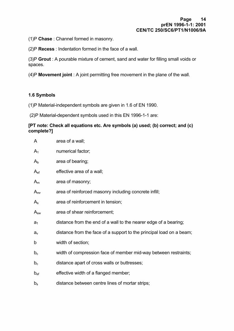
(2)P Material-dependent symbols used in this EN 1996-1-1 are:
[PT note: Check all equations etc. Are symbols (a) used; (b) correct; and (c)complete?]
A area of a wall;
A1 numerical factor;
Ab area of bearing;
Aef effective area of a wall;
Am area of masonry;
Amr area of reinforced masonry including concrete infill;
As area of reinforcement in tension;
Asw area of shear reinforcement;
a1 distance from the end of a wall to the nearer edge of a bearing;
av distance from the face of a support to the principal load on a beam;
b width of section;
bc width of compression face of member mid-way between restraints;
bc distance apart of cross walls or buttresses;
bef effective width of a flanged member;
bs distance between centre lines of mortar strips;
Page 15prEN 1996-1-1: 2001
CEN/TC 250/SC6/PT1/N1006/9A
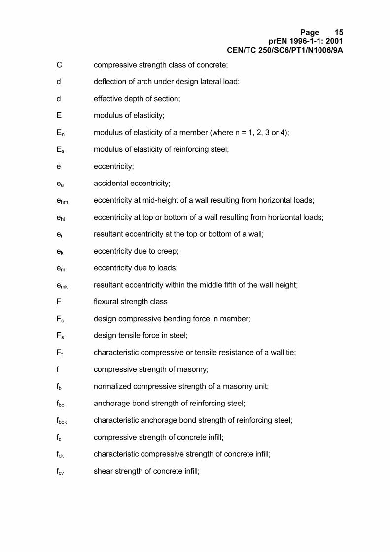
C compressive strength class of concrete;
d deflection of arch under design lateral load;
d effective depth of section;
E modulus of elasticity;
En modulus of elasticity of a member (where n = 1, 2, 3 or 4);
Es modulus of elasticity of reinforcing steel;
e eccentricity;
ea accidental eccentricity;
ehm eccentricity at mid-height of a wall resulting from horizontal loads;
ehi eccentricity at top or bottom of a wall resulting from horizontal loads;
ei resultant eccentricity at the top or bottom of a wall;
ek eccentricity due to creep;
em eccentricity due to loads;
emk resultant eccentricity within the middle fifth of the wall height;
F flexural strength class
Fc design compressive bending force in member;
Fs design tensile force in steel;
Ft characteristic compressive or tensile resistance of a wall tie;
f compressive strength of masonry;
fb normalized compressive strength of a masonry unit;
fbo anchorage bond strength of reinforcing steel;
fbok characteristic anchorage bond strength of reinforcing steel;
fc compressive strength of concrete infill;
fck characteristic compressive strength of concrete infill;
fcv shear strength of concrete infill;
Page 16prEN 1996-1-1: 2001
CEN/TC 250/SC6/PT1/N1006/9A
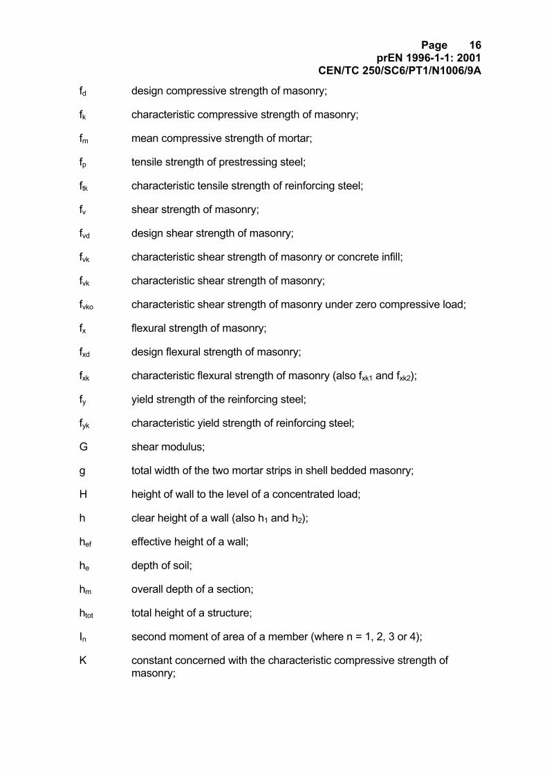
fd design compressive strength of masonry;
fk characteristic compressive strength of masonry;
fm mean compressive strength of mortar;
fp tensile strength of prestressing steel;
ftk characteristic tensile strength of reinforcing steel;
fv shear strength of masonry;
fvd design shear strength of masonry;
fvk characteristic shear strength of masonry or concrete infill;
fvk characteristic shear strength of masonry;
fvko characteristic shear strength of masonry under zero compressive load;
fx flexural strength of masonry;
fxd design flexural strength of masonry;
fxk characteristic flexural strength of masonry (also fxk1 and fxk2);
fy yield strength of the reinforcing steel;
fyk characteristic yield strength of reinforcing steel;
G shear modulus;
g total width of the two mortar strips in shell bedded masonry;
H height of wall to the level of a concentrated load;
h clear height of a wall (also h1 and h2);
hef effective height of a wall;
he depth of soil;
hm overall depth of a section;
htot total height of a structure;
In second moment of area of a member (where n = 1, 2, 3 or 4);
K constant concerned with the characteristic compressive strength ofmasonry;
Page 17prEN 1996-1-1: 2001
CEN/TC 250/SC6/PT1/N1006/9A
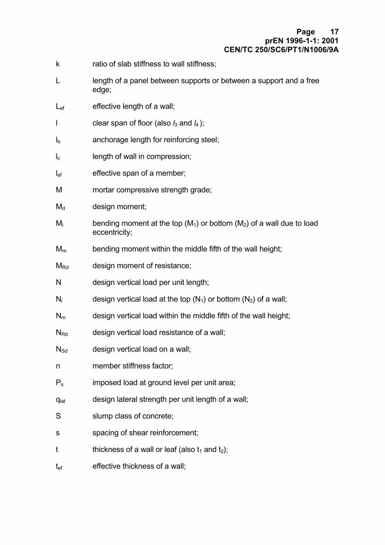
k ratio of slab stiffness to wall stiffness;
L length of a panel between supports or between a support and a freeedge;
Lef effective length of a wall;
l clear span of floor (also l3 and l4 );
lb anchorage length for reinforcing steel;
lc length of wall in compression;
lef effective span of a member;
M mortar compressive strength grade;
Md design moment;
Mi bending moment at the top (M1) or bottom (M2) of a wall due to loadeccentricity;
Mm bending moment within the middle fifth of the wall height;
MRd design moment of resistance;
N design vertical load per unit length;
Ni design vertical load at the top (N1) or bottom (N2) of a wall;
Nm design vertical load within the middle fifth of the wall height;
NRd design vertical load resistance of a wall;
NSd design vertical load on a wall;
n member stiffness factor;
Ps imposed load at ground level per unit area;
qlat design lateral strength per unit length of a wall;
S slump class of concrete;
s spacing of shear reinforcement;
t thickness of a wall or leaf (also t1 and t2);
tef effective thickness of a wall;
Page 18prEN 1996-1-1: 2001
CEN/TC 250/SC6/PT1/N1006/9A
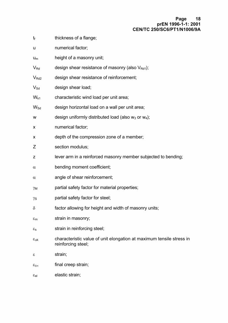
tf thickness of a flange;
u numerical factor;
um height of a masonry unit;
VRd design shear resistance of masonry (also VRd1);
VRd2 design shear resistance of reinforcement;
VSd design shear load;
Wk1 characteristic wind load per unit area;
WSd design horizontal load on a wall per unit area;
w design uniformly distributed load (also w3 or w4);
x numerical factor;
x depth of the compression zone of a member;
Z section modulus;
z lever arm in a reinforced masonry member subjected to bending;
α bending moment coefficient;
α angle of shear reinforcement;
γM partial safety factor for material properties;
γS partial safety factor for steel;
δ factor allowing for height and width of masonry units;
εm strain in masonry;
εs strain in reinforcing steel;
εuk characteristic value of unit elongation at maximum tensile stress inreinforcing steel;
ε strain;
εc∞ final creep strain;
εel elastic strain;
Page 19prEN 1996-1-1: 2001
CEN/TC 250/SC6/PT1/N1006/9A
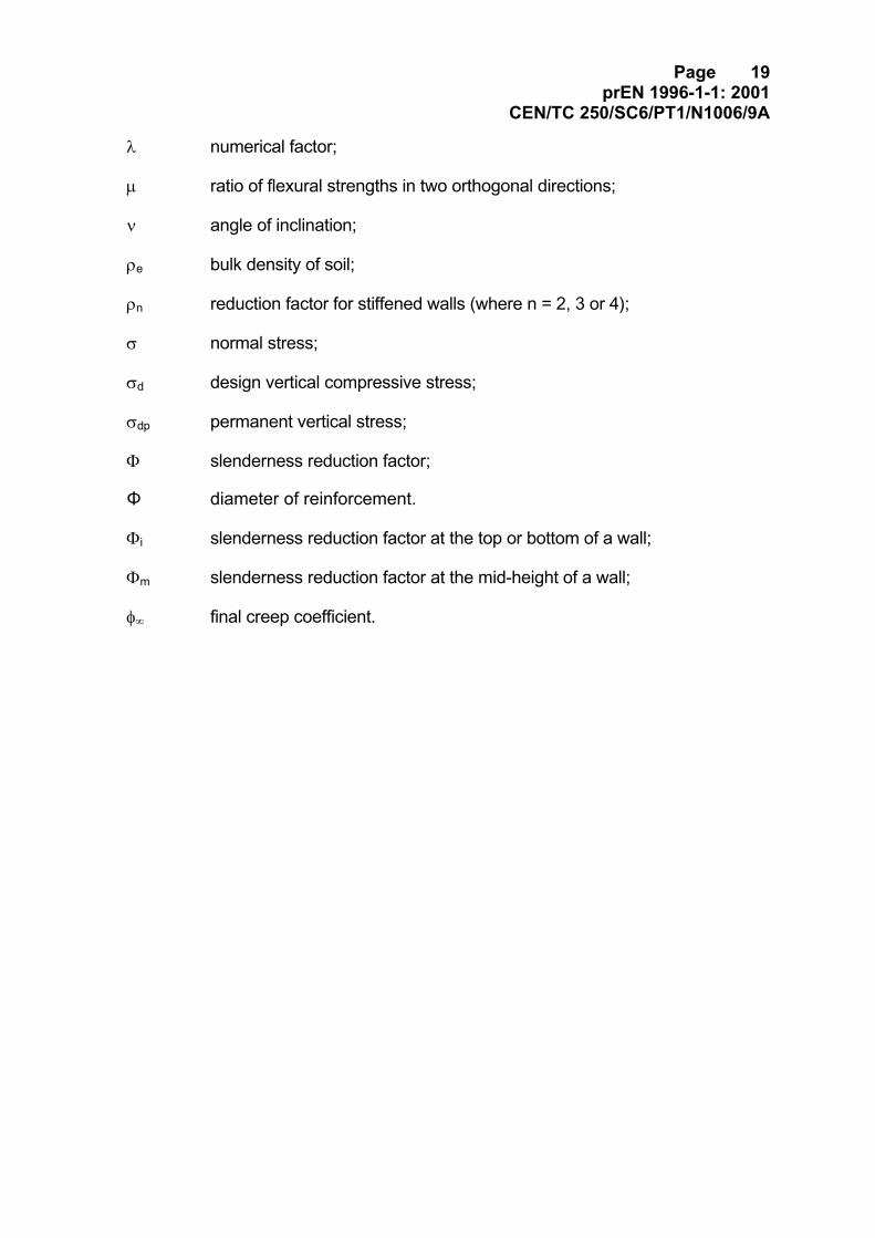
λ numerical factor;
µ ratio of flexural strengths in two orthogonal directions;
ν angle of inclination;
ρe bulk density of soil;
ρn reduction factor for stiffened walls (where n = 2, 3 or 4);
σ normal stress;
σd design vertical compressive stress;
σdp permanent vertical stress;
Φ slenderness reduction factor;
Φ diameter of reinforcement.
Φi slenderness reduction factor at the top or bottom of a wall;
Φm slenderness reduction factor at the mid-height of a wall;
φ∞ final creep coefficient.
Page 20prEN 1996-1-1: 2001
CEN/TC 250/SC6/PT1/N1006/9A
2 Basis of design2.1 Basic requirements
(1)P The design of masonry structures shall be in accordance with the general rulesgiven in EN 1990.
(2)P Specific provisions for masonry structures are given in this section and shall beapplied.
(3) The basic requirements of EN 1990 Section 2 are deemed to be satisfied formasonry structures when the following are applied:
− limit state design in conjunction with the partial factor method described in EN1990
− actions given in EN 1991
− combination rules given in EN 1990
− the principles and rules of application given in this EN 1996-1-1.
2.1.1 Reliability
(1)P The reliability required for masonry structures will be obtained by carrying outdesign according to this EN 1996-1-1.
2.1.3 Design working life and durability
(1) For the consideration of durability reference should be made to Section 4.
2.2 Principles of limit state design
(1)P Limit states may concern only the masonry, or such other materials as are usedfor parts of the structure, for which reference shall be made to relevant parts of EN1992, EN 1993, EN 1994, EN 1995 and EN 1999.
(2)P For masonry structures, the ultimate limit state and serviceability limit state shallbe considered for all aspects of the structure including ancillary components in themasonry.
(3)P For masonry structures, all relevant design solutions including relevant stagesin the sequence of construction shall be considered.
Page 21prEN 1996-1-1: 2001
CEN/TC 250/SC6/PT1/N1006/9A
2.3 Basic variables
2.3.1 Actions
(1)P Actions shall be obtained from the relevant parts of EN 1991.
2.3.2 Design values of actions
(1)P Partial safety factors for load should be obtained from EN 1990.
(2) Partial safety factors for creep and shrinkage of concrete elements in masonrystructures shall be obtained from EN 1992-1
(3) For serviceability limit states, imposed deformations should be introduced asestimated (mean) values.
2.3.3 Material and product properties
(1) Properties for materials and construction products and geometrical data to beused for design should be those specified in the relevant hENs of ETAs, unlessotherwise indicated in this EN 1996-1-1.
2.4 Verification by the partial factor method
2.4.1 Design value of material properties
(1)P The design value for a material property is obtained by dividing thecharacteristic value by the partial safety factor for materials, γM.
2.4.2 Combination of actions
(1)P Combination of actions shall be in accordance with the general rules given inEN 1990.
Note: In normal residential and office structures the imposed loads, as given in EN 1991-1, may betreated as one fixed variable action (that is, equal loading on all spans, or zero, when appropriate)for which reduction factors are given in EN 1991-1, to allow for the unlikely simultaneousapplication of the loads at the same time eg several floors of loading.
Page 22prEN 1996-1-1: 2001
CEN/TC 250/SC6/PT1/N1006/9A
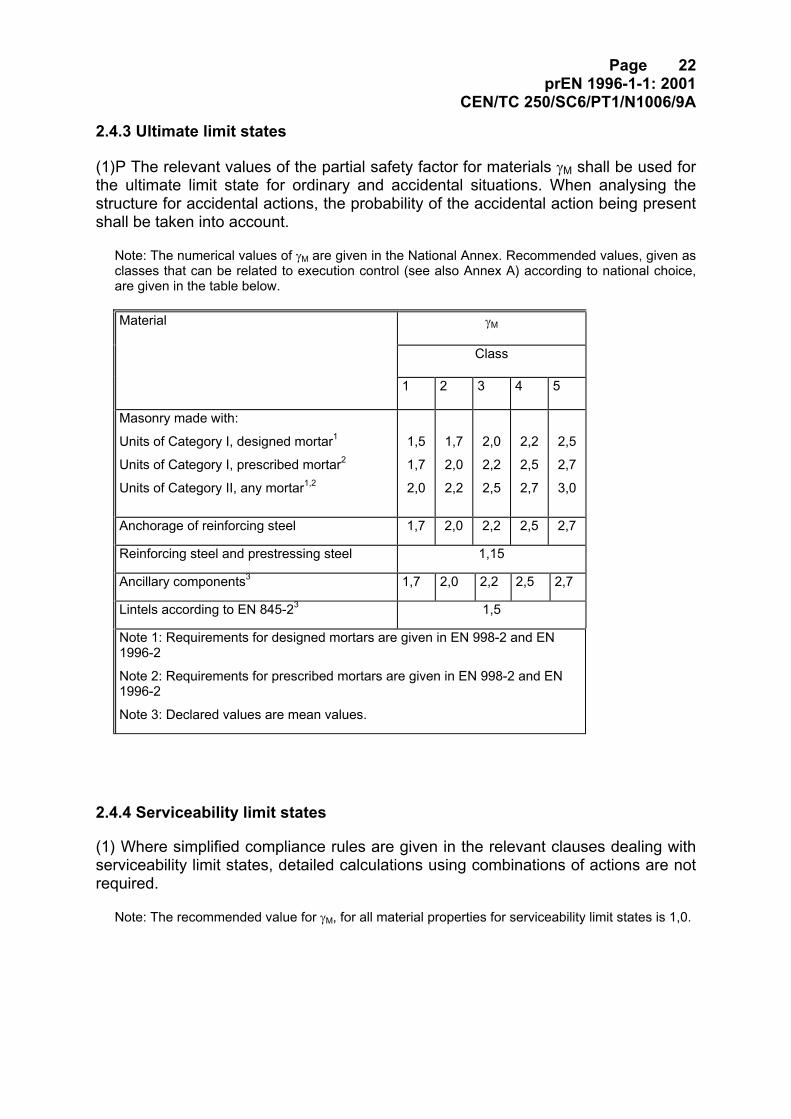
2.4.3 Ultimate limit states
(1)P The relevant values of the partial safety factor for materials γM shall be used forthe ultimate limit state for ordinary and accidental situations. When analysing thestructure for accidental actions, the probability of the accidental action being presentshall be taken into account.
Note: The numerical values of γM are given in the National Annex. Recommended values, given asclasses that can be related to execution control (see also Annex A) according to national choice,are given in the table below.
γMMaterial
Class
1 2 3 4 5
Masonry made with:
Units of Category I, designed mortar1
Units of Category I, prescribed mortar2
Units of Category II, any mortar1,2
1,5
1,7
2,0
1,7
2,0
2,2
2,0
2,2
2,5
2,2
2,5
2,7
2,5
2,7
3,0
Anchorage of reinforcing steel 1,7 2,0 2,2 2,5 2,7
Reinforcing steel and prestressing steel 1,15
Ancillary components3 1,7 2,0 2,2 2,5 2,7
Lintels according to EN 845-23 1,5
Note 1: Requirements for designed mortars are given in EN 998-2 and EN1996-2
Note 2: Requirements for prescribed mortars are given in EN 998-2 and EN1996-2
Note 3: Declared values are mean values.
2.4.4 Serviceability limit states
(1) Where simplified compliance rules are given in the relevant clauses dealing withserviceability limit states, detailed calculations using combinations of actions are notrequired.
Note: The recommended value for γM, for all material properties for serviceability limit states is 1,0.
Page 23prEN 1996-1-1: 2001
CEN/TC 250/SC6/PT1/N1006/9A
2.5 Design assisted by testing
(1) Structural properties of masonry may be determined by testing.
Note: Annex D (informative) of EN 1990 gives recommendations for design assisted by testing.
.
Page 24prEN 1996-1-1: 2001
CEN/TC 250/SC6/PT1/N1006/9A
3 Materials
3.1 Masonry Units
3.1.1 Types and grouping of masonry units
(1)P Masonry units shall comply with any of the following types:
- clay units in accordance with EN 771-1.
- calcium silicate units in accordance with EN 771-2.
- aggregate concrete units (dense and lightweight aggregate) in accordance with EN771-3.
- autoclaved aerated concrete units in accordance with EN 771-4.
- manufactured stone units in accordance with EN 771-5.
- dimensioned natural stone units in accordance with EN 771-6.
(2) Masonry units may be Category I or Category II.
(3) Masonry units should be grouped as Group 1, Group 2, Group 3 or Group 4, for thepurposes of using the equations and other numerical values given in 3.6.1 and 3.6.2and where grouping is referred to in other clauses.
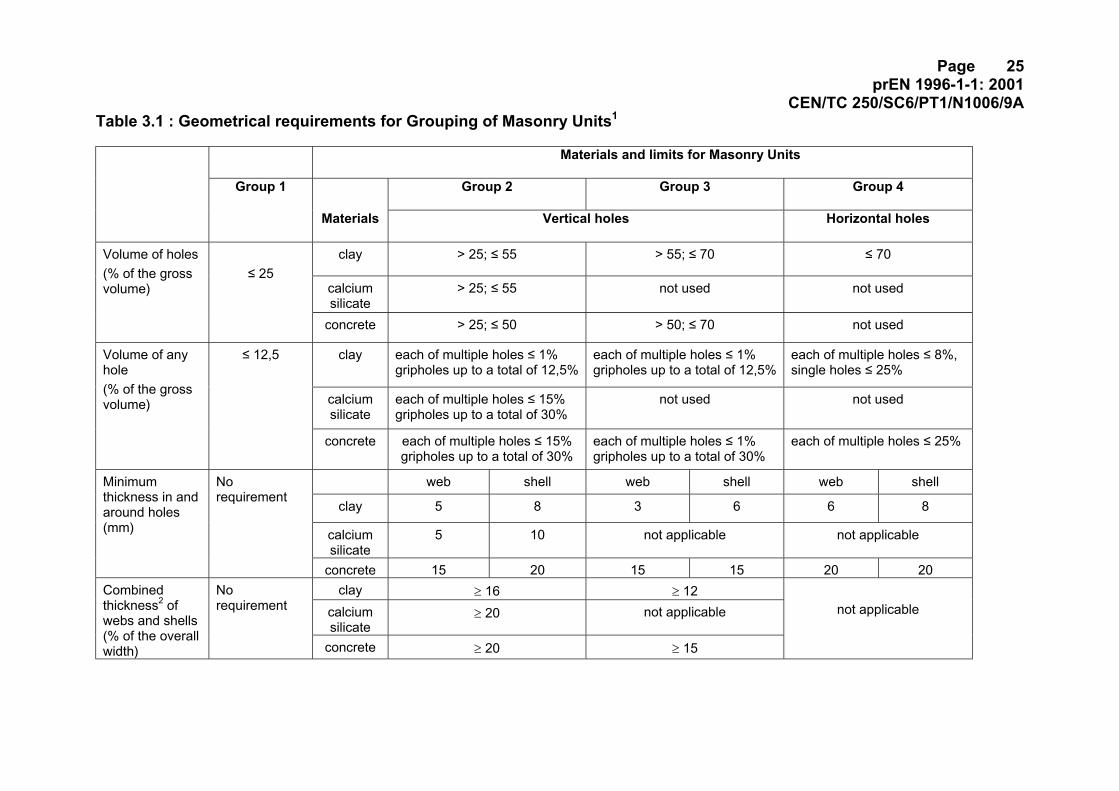
(4) The limitations on the geometry of units, ie percentage of holes, volume of holes,minimum thickness of material between the face of a unit and a hole, or the minimumthickness of material between holes in the unit, need to be determined so that theperformance of the type of units in masonry can be represented by the relationshipsgiven in 3.6.1 and 3.6.2 with the compressive strength of the units. It can be assumedthat the limits on the geometry of units, as given in table 3.1, will satisfy thisrequirement.
Page 25prEN 1996-1-1: 2001
CEN/TC 250/SC6/PT1/N1006/9ATable 3.1 : Geometrical requirements for Grouping of Masonry Units1
Materials and limits for Masonry Units
Group 1 Group 2 Group 3 Group 4
Materials Vertical holes Horizontal holes
clay > 25; ≤ 55 > 55; ≤ 70 ≤ 70
calciumsilicate
> 25; ≤ 55 not used not used
Volume of holes(% of the grossvolume)
≤ 25
concrete > 25; ≤ 50 > 50; ≤ 70 not used
clay each of multiple holes ≤ 1%gripholes up to a total of 12,5%
each of multiple holes ≤ 1%gripholes up to a total of 12,5%
each of multiple holes ≤ 8%,single holes ≤ 25%
calciumsilicate
each of multiple holes ≤ 15%gripholes up to a total of 30%
not used not used
Volume of anyhole(% of the grossvolume)
≤ 12,5
concrete each of multiple holes ≤ 15%gripholes up to a total of 30%
each of multiple holes ≤ 1%gripholes up to a total of 30%
each of multiple holes ≤ 25%
web shell web shell web shell
clay 5 8 3 6 6 8
calciumsilicate
5 10 not applicable not applicable
Minimumthickness in andaround holes(mm)
Norequirement
concrete 15 20 15 15 20 20clay ≥ 16 ≥ 12
calciumsilicate
≥ 20 not applicableCombinedthickness2 ofwebs and shells(% of the overallwidth)
Norequirement
concrete ≥ 20 ≥ 15
not applicable
Page 26prEN 1996-1-1: 2001
CEN/TC 250/SC6/PT1/N1006/9ANotes:
1. The limits given above are for masonry units used in masonry designed using the numerical values of equations in 3.6.1 and 3.6.2 (see 3.1.1(3)).
2. The combined thickness is the thickness of the webs and shells, measured horizontally across the unit at right angles to the face of the wall. In the case ofconical holes, or cellular holes, use the mean value of the thickness of the webs and the shells. The check is to be seen as qualification test and need only berepeated in the case of principal changes to the design dimensions of units.
Page 27prEN 1996-1-1: 2001
CEN/TC 250/SC6/PT1/N1006/9A
3.1.2 Properties of masonry units
3.1.2.1 Compressive strength of masonry units
(1)P The compressive strength of masonry units, to be used in design, shall be thenormalized compressive strength, fb.
Note: It will normally be given by a manufacturer as the declared normalised strength - see EN 771series.
(2) When the compressive strength of masonry units is declared as a characteristicstrength this should be converted to the mean equivalent, using a factor based on thecoefficient of variation of the units.
3.2 Mortar
3.2.1 Types of masonry mortar
(1) Masonry mortars are defined as general purpose, thin layer or lightweight mortaraccording to their constituents.
(2) Masonry mortars are considered as designed or prescribed mortars according tothe method of defining their composition.
(3) Masonry mortars may be factory made (prebatched or premixed), semi-finishedfactory made, site-made, or pre-mixed, according to the method of manufacture.
(4) Factory made and semi-finished factory made masonry mortars shall be inaccordance with EN 998-2. Site-made masonry mortar shall be in accordance with EN1996-2. Pre-mixed lime and sand masonry mortar shall be in accordance with EN 998-2, and shall be used in accordance with EN 998-2.
3.2.2 Specification of masonry mortar
(1) Mortars should be classified by their compressive strength, expressed as the letterM followed by the compressive strength in N/mm², for example, M5. Prescribedmasonry mortars, additionally to the M number, will be described by their prescribedconstituents, eg 1: 1: 5 cement: lime: sand by volume.
Note: The National Annex of any country may ascribe acceptable equivalent mixes described by theproportion of the constituents, to stated M values.
(2) General purpose masonry mortars may be designed mortars in accordance with EN998-2 or prescribed masonry mortars to EN 998-2.
Page 28prEN 1996-1-1: 2001
CEN/TC 250/SC6/PT1/N1006/9A
(3) Thin layer masonry mortars should be designed mortars in accordance with EN998-2.
(4) Lightweight masonry mortars should be designed mortars in accordance with EN 998-2.
3.2.3 Properties of mortar
3.2.3.1 Compressive strength of masonry mortar
(1)P The compressive strength of masonry mortar, fm , shall be determined inaccordance with EN 1015-11.
(2) Masonry mortars should not have a compressive strength fm less than 1 N/mm2.
3.2.3.2 Adhesion between units and mortar
(1)P The adhesion between the mortar and the masonry units shall be adequate for theintended use.
Note 1: Adequate adhesion will depend on the type of mortar used and the units to which that mortaris applied. Mortars in accordance with EN 998-2 and site mixed designed or site mixed prescribedgeneral purpose mortars made in accordance with EN 1996-2, will normally give adequate adhesionwith most units when constructed in accordance with EN 1996-2.
Note 2: EN 1052-3, deals with the determination of the initial shear strength of masonry and prEN1052-5, under preparation, deals with the determination of flexural bond strength
3.3 Concrete infill
3.3.1 General
(1)P Concrete used for infill shall be in accordance with EN 206.
(2) Concrete infill is specified by the characteristic compressive strength, fck, (concretestrength class), which relates to the cylinder/cube strength at 28 days, in accordancewith EN 206.
3.3.2 Specification for concrete infill
(1) The strength class, as defined in EN 206, of concrete infill should be not less than12/15 N/mm2.
Page 29prEN 1996-1-1: 2001
CEN/TC 250/SC6/PT1/N1006/9A
(2) The concrete may be designed or prescribed and should contain just sufficientwater to provide the specified strength and to give adequate workability.
(3)P The workability of concrete infill shall be such as to ensure that voids will becompletely filled, when the concrete is placed in accordance with EN 1996-2.
(4) The slump class S3 to S5 or flow class F4 to F6, in accordance with EN 206, willbe satisfactory for most cases. In holes, where the smaller dimension is less than 85mm, slump classes S5 or S6 should be used. Where high slump concretes are to beused, measures need to be taken to reduce the resulting high shrinkage of theconcrete.
(5) The maximum aggregate size of concrete infill should not exceed 20mm. Whenconcrete infill is to be used in voids whose least dimension is less than 100mm orwhen the cover to the reinforcement is less than 25mm, the maximum aggregatesize should not exceed 10mm.
3.3.3 Properties of concrete infill
(1)P The characteristic compressive strength and shear strength of concrete infillshall be determined from tests on concrete specimens.
Note: Test results may be obtained from tests carried out for the project, or be available from adatabase.
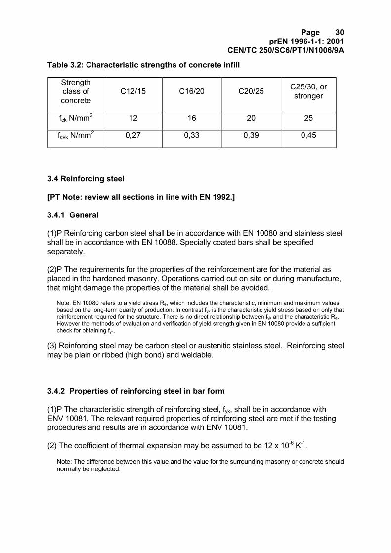
(2) Where test data is not available the characteristic compressive strength, fck, andthe characteristic shear strength, fcvk, of concrete infill may be taken from table 3.2.
Page 30prEN 1996-1-1: 2001
CEN/TC 250/SC6/PT1/N1006/9A
Table 3.2: Characteristic strengths of concrete infill
Strengthclass ofconcrete
C12/15 C16/20 C20/25 C25/30, orstronger
fck N/mm2 12 16 20 25
fcvk N/mm2 0,27 0,33 0,39 0,45
3.4 Reinforcing steel
[PT Note: review all sections in line with EN 1992.]
3.4.1 General
(1)P Reinforcing carbon steel shall be in accordance with EN 10080 and stainless steelshall be in accordance with EN 10088. Specially coated bars shall be specifiedseparately.
(2)P The requirements for the properties of the reinforcement are for the material asplaced in the hardened masonry. Operations carried out on site or during manufacture,that might damage the properties of the material shall be avoided.
Note: EN 10080 refers to a yield stress Re, which includes the characteristic, minimum and maximum valuesbased on the long-term quality of production. In contrast fyk is the characteristic yield stress based on only thatreinforcement required for the structure. There is no direct relationship between fyk and the characteristic Re.However the methods of evaluation and verification of yield strength given in EN 10080 provide a sufficientcheck for obtaining fyk.
(3) Reinforcing steel may be carbon steel or austenitic stainless steel. Reinforcing steelmay be plain or ribbed (high bond) and weldable.
3.4.2 Properties of reinforcing steel in bar form
(1)P The characteristic strength of reinforcing steel, fyk, shall be in accordance withENV 10081. The relevant required properties of reinforcing steel are met if the testingprocedures and results are in accordance with ENV 10081.
(2) The coefficient of thermal expansion may be assumed to be 12 x 10-6 K-1.
Note: The difference between this value and the value for the surrounding masonry or concrete shouldnormally be neglected.
Page 31prEN 1996-1-1: 2001
CEN/TC 250/SC6/PT1/N1006/9A
3.4.3 Properties of prefabricated bed joint reinforcement
(1) Prefabricated bed joint reinforcement should be in accordance with EN 845-3.
3.5 Prestressing steel
3.5.1 General
(1)P Prestressing steel shall be in accordance with EN 10138.
(2) The properties of prestressing steel should be obtained from EN 1992-1-1.
3.6 Mechanical properties of masonry
3.6.1 Characteristic compressive strength of masonry
3.6.1.1 General
(1)P The characteristic compressive strength of masonry, fk , shall be determined fromresults of tests on masonry specimens.
Note: Test results may be obtained from tests carried out for the project, or be available from adatabase.
(2) The characteristic compressive strength of masonry should be determined fromtests in accordance with EN 1052-1, or it may be established from an evaluation of testdata.
3.6.1.2 Characteristic compressive strength of masonry made with filled verticaljoints
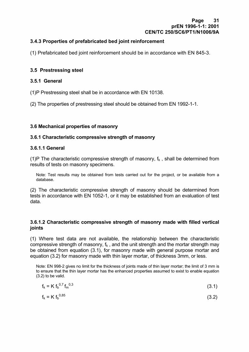
(1) Where test data are not available, the relationship between the characteristiccompressive strength of masonry, fk , and the unit strength and the mortar strength maybe obtained from equation (3.1), for masonry made with general purpose mortar andequation (3.2) for masonry made with thin layer mortar, of thickness 3mm, or less.
Note: EN 998-2 gives no limit for the thickness of joints made of thin layer mortar; the limit of 3 mm isto ensure that the thin layer mortar has the enhanced properties assumed to exist to enable equation(3.2) to be valid.
fk = K fb0,7 fm0,3 (3.1)
fk = K fb0,85 (3.2)
Page 32prEN 1996-1-1: 2001
CEN/TC 250/SC6/PT1/N1006/9A
where:
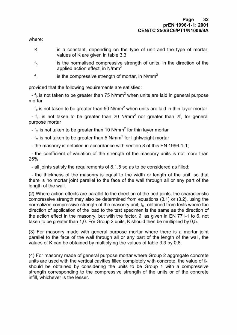
K is a constant, depending on the type of unit and the type of mortar;values of K are given in table 3.3
fb is the normalised compressive strength of units, in the direction of theapplied action effect, in N/mm2
fm is the compressive strength of mortar, in N/mm2
provided that the following requirements are satisfied:- fb is not taken to be greater than 75 N/mm2 when units are laid in general purpose
mortar- fb is not taken to be greater than 50 N/mm2 when units are laid in thin layer mortar- fm is not taken to be greater than 20 N/mm2 nor greater than 2fb for general
purpose mortar- fm is not taken to be greater than 10 N/mm2 for thin layer mortar- fm is not taken to be greater than 5 N/mm2 for lightweight mortar- the masonry is detailed in accordance with section 8 of this EN 1996-1-1;- the coefficient of variation of the strength of the masonry units is not more than
25%;- all joints satisfy the requirements of 8.1.5 so as to be considered as filled;- the thickness of the masonry is equal to the width or length of the unit, so that
there is no mortar joint parallel to the face of the wall through all or any part of thelength of the wall.(2) Where action effects are parallel to the direction of the bed joints, the characteristiccompressive strength may also be determined from equations (3.1) or (3.2), using thenormalized compressive strength of the masonry unit, fb , obtained from tests where thedirection of application of the load to the test specimen is the same as the direction ofthe action effect in the masonry, but with the factor, δ, as given in EN 771-1 to 6, nottaken to be greater than 1,0. For Group 2 units, K should then be multiplied by 0,5.
(3) For masonry made with general purpose mortar where there is a mortar jointparallel to the face of the wall through all or any part of the length of the wall, thevalues of K can be obtained by multiplying the values of table 3.3 by 0,8.
(4) For masonry made of general purpose mortar where Group 2 aggregate concreteunits are used with the vertical cavities filled completely with concrete, the value of fb,should be obtained by considering the units to be Group 1 with a compressivestrength corresponding to the compressive strength of the units or of the concreteinfill, whichever is the lesser.
Page 33prEN 1996-1-1: 2001
CEN/TC 250/SC6/PT1/N1006/9A
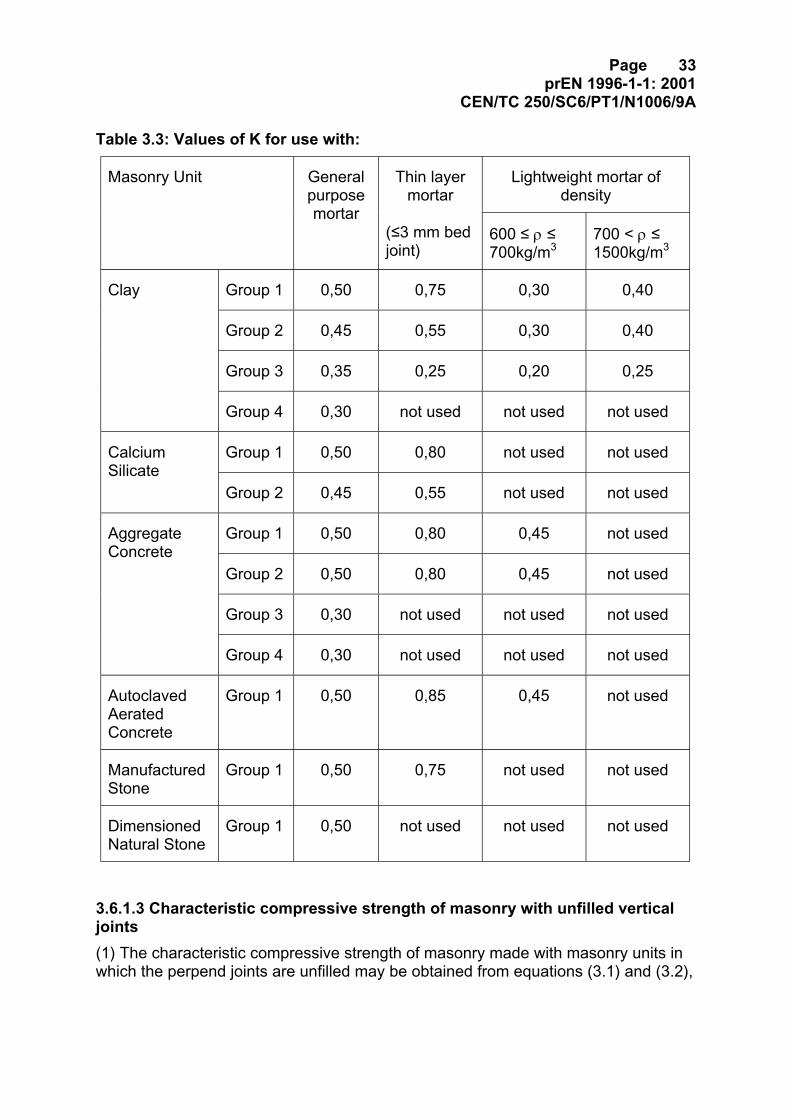
Table 3.3: Values of K for use with:
Lightweight mortar ofdensity
Masonry Unit Generalpurposemortar
Thin layermortar
(≤3 mm bedjoint)
600 ≤ ρ ≤700kg/m3
700 < ρ ≤1500kg/m3
Group 1 0,50 0,75 0,30 0,40
Group 2 0,45 0,55 0,30 0,40
Group 3 0,35 0,25 0,20 0,25
Clay
Group 4 0,30 not used not used not used
Group 1 0,50 0,80 not used not usedCalciumSilicate
Group 2 0,45 0,55 not used not used
Group 1 0,50 0,80 0,45 not used
Group 2 0,50 0,80 0,45 not used
Group 3 0,30 not used not used not used
AggregateConcrete
Group 4 0,30 not used not used not used
AutoclavedAeratedConcrete
Group 1 0,50 0,85 0,45 not used
ManufacturedStone
Group 1 0,50 0,75 not used not used
DimensionedNatural Stone
Group 1 0,50 not used not used not used
3.6.1.3 Characteristic compressive strength of masonry with unfilled verticaljoints(1) The characteristic compressive strength of masonry made with masonry units inwhich the perpend joints are unfilled may be obtained from equations (3.1) and (3.2),
Page 34prEN 1996-1-1: 2001
CEN/TC 250/SC6/PT1/N1006/9A
provided that the shear resistance is based upon the requirements of 3.6.2(7) anddue consideration is given to any horizontal actions that might be applied to, or betransmitted by, the masonry.
3.6.1.4 Characteristic compressive strength of shell bedded masonry(1) The characteristic compressive strength of shell bedded masonry, made with Group1 and Group 4 masonry units and bedded on two or more equal strips of generalpurpose mortar, two of which are at the outside edges of the bed face of the units, maybe obtained from equation (3.1) for general purpose and lightweight mortar andequation (3.2) for the thin layer mortar in beds not more than 3mm thick, provided that:- the width of each strip of mortar is 30 mm or greater;- the thickness of the masonry is equal to the width or length of the masonry units sothat there is no longitudinal mortar joint through all or part of the length of the wall;- the ratio g/t is not less than 0,4;- K is taken from table 3.3 when g/t = 1,0 or K is taken as 0,22 when g/t = 0,4, withintermediate values obtained by linear interpolation,where:
g is the total width of the mortar strips;t is the thickness of the wall.
(2) The characteristic compressive strength of shell bedded masonry made withGroup 2 masonry units and bedded as noted for Group 1 masonry units, may beobtained from equation (3.1) provided that the normalised compressive strength ofthe units, fb, used in the equation is that obtained from tests on units shell beddedwith strips of mortar, no wider than those intended to be used in the masonry, butbasing the strength of the unit on the gross area of the unit, not the bedded area.
3.6.2 Characteristic shear strength of masonry
(1)P The characteristic shear strength of masonry, fvk , shall be determined from theresults of tests on masonry.
Note: Test results may be obtained from tests carried out for the project, or be available from adatabase.
(2) The characteristic initial shear strength of masonry, fvko , should be determined fromtests in accordance with EN 1052-3 or EN 1052-4 or it may be established from anevaluation of test data.
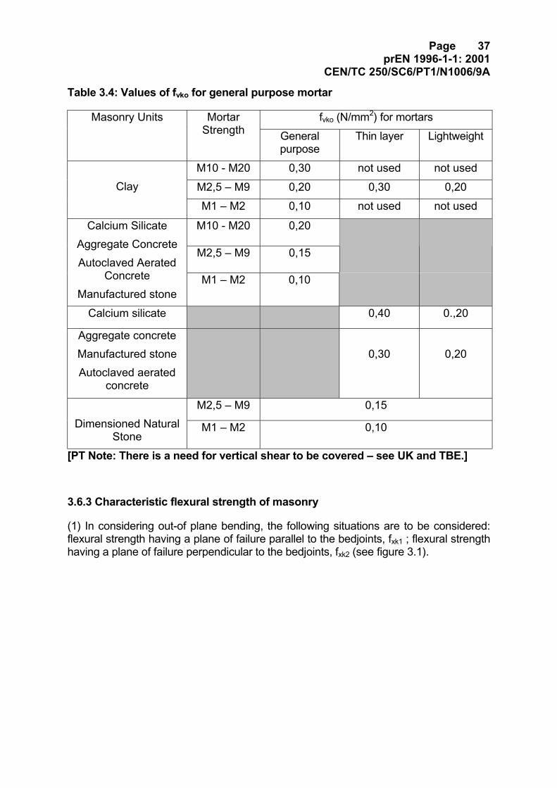
(3) Where test data are not available, values for the initial shear strength of masonrymade with general purpose mortar, thin layer mortar in beds not greater than 3mm thickand lightweight mortar, may be taken from table 3.4.
Page 35prEN 1996-1-1: 2001
CEN/TC 250/SC6/PT1/N1006/9A
(4) The characteristic shear strength of masonry, fvk , using general purpose mortar inaccordance with 3.2.2.1(2) and (3), or thin layer mortar in beds not greater than 3mmthick, in accordance with 3.2.2.1(4), or lightweight mortar in accordance with 3.2.2.1(5)with all joints satisfying the requirements of 8.1.5 so as to be considered as filled, maybe taken from equations (3.3a to c), whichever gives the lowest value, for theappropriate Groups.
fvk = fvko + 0,4 σd (3.3a)
or fvk = (0,034 fb + 0,14 σd) for Group 1 and 4 units (3.3b)
or fvk = 0,9 (0,034 fb + 0,14 σd) for Group 2 and 3(3.3c)
where:
fvko is the characteristic initial shear strength, under zero compressive stress;
σd is the design compressive stress perpendicular to the shear in the memberat the level under consideration, using the appropriate load combination;
fb is the normalized compressive strength of the masonry units, as describedin 3.1.2.1, for the direction of application of the load on the test specimensbeing perpendicular to the bed face.
[PT Notes: shear in basements; suggestion to tabulate.]
(5) The characteristic shear strength for unreinforced masonry using general purposemortar in accordance with 3.2.2.1(2) and (3), or thin layer mortar in accordance with3.2.2.1, in beds not greater than 3 mm thick, or lightweight mortar in accordance with3.2.2.1, and having the perpend joints unfilled, but with adjacent faces of the masonryunits closely abutted together, may be taken from equations (3.4a to c), whichevergives the lowest value for the relevant units.
fvk = 0,5 fvko + 0,4 σd (3.4a)
or fvk = 0,7 (0,034 fb + 0,14 σd) for Group 1 and 4 units, (3.4b)
or fvk = 0,6 (0,034 fb + 0,14 σd ) for Group 2 and 3 units (3.4c)
where
fvko , σd and fb are as defined in (3) above.
(6) In shell bedded masonry, made with Group 1 masonry units and bedded on two ormore equal strips of general purpose mortar, each at least 30mm in width, two of whichare at the outside edges of the bed face of the unit, may be taken from equations (3.5aand b), whichever gives the lowest value, for the relevant Group 1, 2 or 3 units.
Page 36prEN 1996-1-1: 2001
CEN/TC 250/SC6/PT1/N1006/9A
σdvkovk 0,4 + f tg = f (3.5a)
or fvk = the value obtained from equations (3.4b) or (3.4c) (3.5b)
where
fvko , σd and fb are as defined in (4) above and:
g is the total width of the mortar strips;
t is the thickness of the wall.
[PT Note: It is recognised that the 0.4σd part of the equation does not really needto be divided by M, but it is not reasonable to ignore a material safety factor so ithas not been changed.]
Page 37prEN 1996-1-1: 2001
CEN/TC 250/SC6/PT1/N1006/9A
Table 3.4: Values of fvko for general purpose mortar
fvko (N/mm2) for mortarsMasonry Units MortarStrength General
purposeThin layer Lightweight
M10 - M20 0,30 not used not usedM2,5 – M9 0,20 0,30 0,20Clay
M1 – M2 0,10 not used not used
M10 - M20 0,20
M2,5 – M9 0,15
Calcium SilicateAggregate ConcreteAutoclaved Aerated
ConcreteManufactured stone
M1 – M2 0,10
Calcium silicate 0,40 0.,20
Aggregate concreteManufactured stoneAutoclaved aerated
concrete
0,30 0,20
M2,5 – M9 0,15Dimensioned Natural
StoneM1 – M2 0,10
[PT Note: There is a need for vertical shear to be covered – see UK and TBE.]
3.6.3 Characteristic flexural strength of masonry
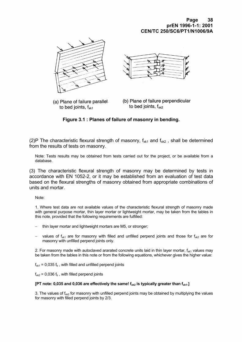
(1) In considering out-of plane bending, the following situations are to be considered:flexural strength having a plane of failure parallel to the bedjoints, fxk1 ; flexural strengthhaving a plane of failure perpendicular to the bedjoints, fxk2 (see figure 3.1).
Page 38prEN 1996-1-1: 2001
CEN/TC 250/SC6/PT1/N1006/9A
Figure 3.1 : Planes of failure of masonry in bending.
(2)P The characteristic flexural strength of masonry, fxk1 and fxk2 , shall be determinedfrom the results of tests on masonry.
Note: Tests results may be obtained from tests carried out for the project, or be available from adatabase.
(3) The characteristic flexural strength of masonry may be determined by tests inaccordance with EN 1052-2, or it may be established from an evaluation of test databased on the flexural strengths of masonry obtained from appropriate combinations ofunits and mortar.
Note:
1. Where test data are not available values of the characteristic flexural strength of masonry madewith general purpose mortar, thin layer mortar or lightweight mortar, may be taken from the tables inthis note, provided that the following requirements are fulfilled:
− thin layer mortar and lightweight mortars are M5, or stronger;
− values of fxk1 are for masonry with filled and unfilled perpend joints and those for fxk2 are formasonry with unfilled perpend joints only.
2. For masonry made with autoclaved ararated concrete units laid in thin layer mortar, fxk1 values maybe taken from the tables in this note or from the following equations, whichever gives the higher value:
fxk1 = 0,035 fb , with filled and unfilled perpend joints
fxk2 = 0,036 fb , with filled perpend joints
[PT note: 0,035 and 0,036 are effectively the same! fxk2 is typically greater than fxk1.]
3. The values of fxk2 for masonry with unfilled perpend joints may be obtained by multiplying the valuesfor masonry with filled perpend joints by 2/3.
Page 39prEN 1996-1-1: 2001
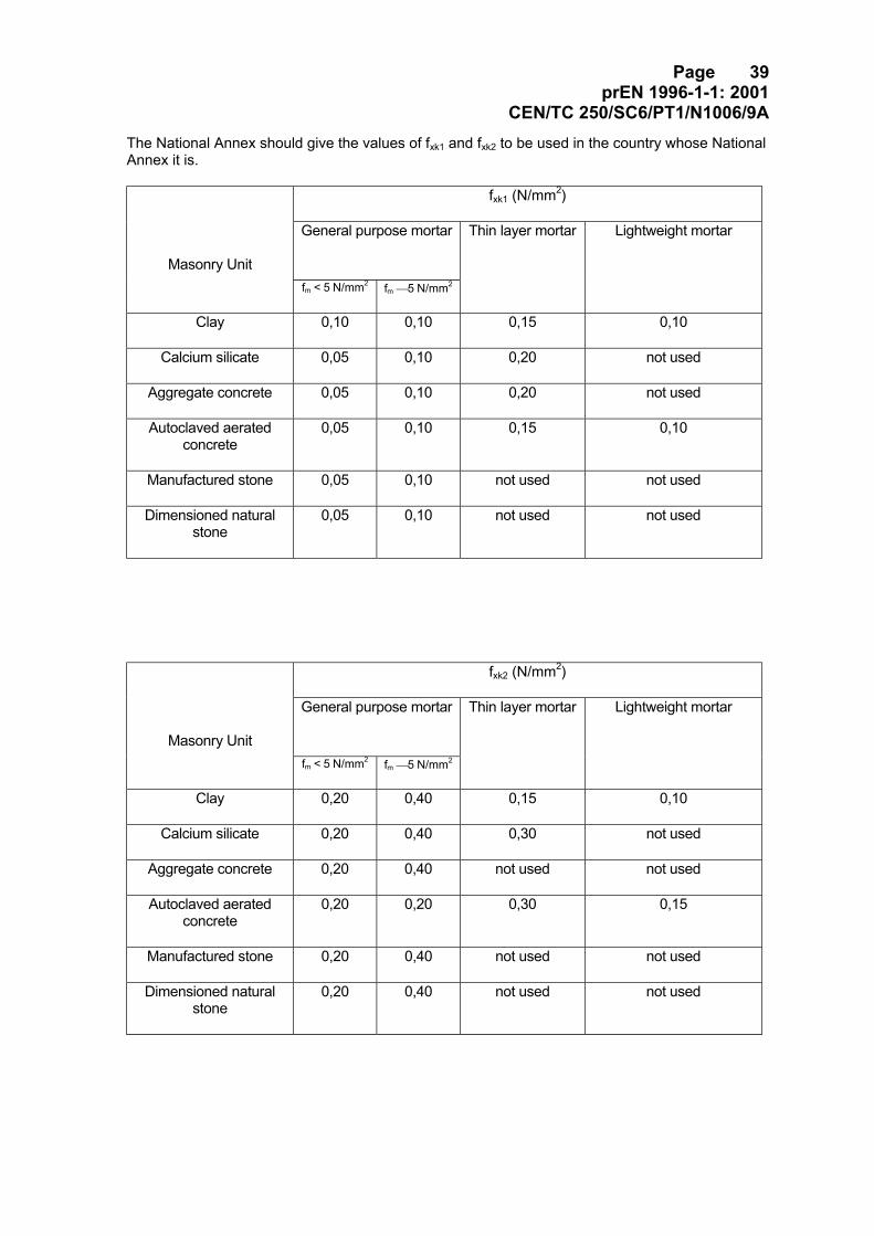
CEN/TC 250/SC6/PT1/N1006/9AThe National Annex should give the values of fxk1 and fxk2 to be used in the country whose NationalAnnex it is.
fxk1 (N/mm2)
General purpose mortar
Masonry Unitfm < 5 N/mm2 fm 5 N/mm2
Thin layer mortar Lightweight mortar
Clay 0,10 0,10 0,15 0,10
Calcium silicate 0,05 0,10 0,20 not used
Aggregate concrete 0,05 0,10 0,20 not used
Autoclaved aeratedconcrete
0,05 0,10 0,15 0,10
Manufactured stone 0,05 0,10 not used not used
Dimensioned naturalstone
0,05 0,10 not used not used
fxk2 (N/mm2)
General purpose mortar
Masonry Unitfm < 5 N/mm2 fm 5 N/mm2
Thin layer mortar Lightweight mortar
Clay 0,20 0,40 0,15 0,10
Calcium silicate 0,20 0,40 0,30 not used
Aggregate concrete 0,20 0,40 not used not used
Autoclaved aeratedconcrete
0,20 0,20 0,30 0,15
Manufactured stone 0,20 0,40 not used not used
Dimensioned naturalstone
0,20 0,40 not used not used
Page 40prEN 1996-1-1: 2001
CEN/TC 250/SC6/PT1/N1006/9A
[PT Note: the old (4) has been deleted. This contained a warning concerningpoor bond - is a form of warning needed?]
3.6.4 Characteristic anchorage strength
(1)P The characteristic anchorage strength of reinforcement bedded in concrete shallbe obtained from the results of tests.
Note: Test results may be obtained from tests carried out for the project, or be available from adatabase.
(2) The characteristic anchorage strength of reinforcement may be established froman evaluation of test data.
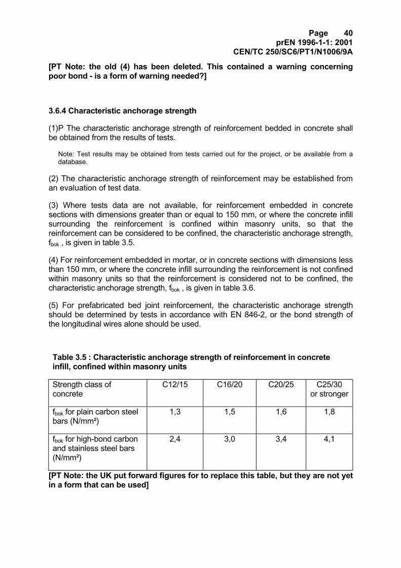
(3) Where tests data are not available, for reinforcement embedded in concretesections with dimensions greater than or equal to 150 mm, or where the concrete infillsurrounding the reinforcement is confined within masonry units, so that thereinforcement can be considered to be confined, the characteristic anchorage strength,fbok , is given in table 3.5.
(4) For reinforcement embedded in mortar, or in concrete sections with dimensions lessthan 150 mm, or where the concrete infill surrounding the reinforcement is not confinedwithin masonry units so that the reinforcement is considered not to be confined, thecharacteristic anchorage strength, fbok , is given in table 3.6.
(5) For prefabricated bed joint reinforcement, the characteristic anchorage strengthshould be determined by tests in accordance with EN 846-2, or the bond strength ofthe longitudinal wires alone should be used.
Table 3.5 : Characteristic anchorage strength of reinforcement in concreteinfill, confined within masonry units
Strength class ofconcrete
C12/15 C16/20 C20/25 C25/30or stronger
fbok for plain carbon steelbars (N/mm²)
1,3 1,5 1,6 1,8
fbok for high-bond carbonand stainless steel bars(N/mm²)
2,4 3,0 3,4 4,1
[PT Note: the UK put forward figures for to replace this table, but they are not yetin a form that can be used]
Page 41prEN 1996-1-1: 2001
CEN/TC 250/SC6/PT1/N1006/9A
Table 3.6 : Characteristic anchorage strength of reinforcement in mortar orconcrete not confined within masonry units
Mortar M5-M9 M10-M14 M15-M19 M20Strengthclass of:
Concrete C12/15 C16/20 C20/25 C25/30 orstronger
fbok for plain carbon steelbars (N/mm²)
0,7 1,2 1,4 1,5
fbok for high-bond carbonsteel and stainless steelbars (N/mm²)
1,0 1,5 2,0 2,5
3.7 Deformation properties of masonry
3.7.1 Stress-strain relationship
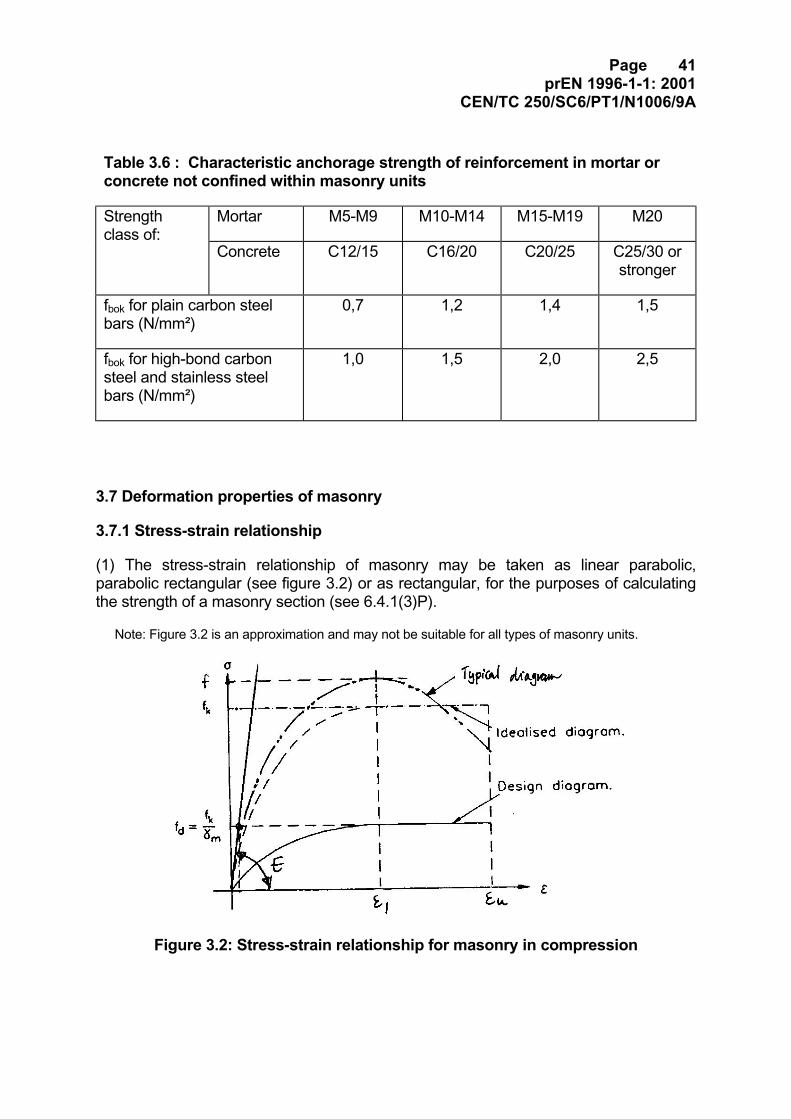
(1) The stress-strain relationship of masonry may be taken as linear parabolic,parabolic rectangular (see figure 3.2) or as rectangular, for the purposes of calculatingthe strength of a masonry section (see 6.4.1(3)P).
Note: Figure 3.2 is an approximation and may not be suitable for all types of masonry units.
Figure 3.2: Stress-strain relationship for masonry in compression
Page 42prEN 1996-1-1: 2001
CEN/TC 250/SC6/PT1/N1006/9A
3.7.2 Modulus of elasticity
(1)P The short term secant modulus of elasticity, E , shall be determined by tests inaccordance with EN 1052-1.
Note: Test results may be obtained from tests carried out for the project, or be available from adatabase.
(2) In the absence of a value determined by tests in accordance with EN 1052-1, theshort term secant modulus of elasticity of masonry, E , for use in structural analysis,may be taken to be 1000 fk.
(3) The long term modulus should be based on the short term secant value, reduced toallow for creep effects, (see 3.7.4), such that:
∞φ+
=1 E E term short
term long (3.6)
where
φ∞ is the final creep coefficient.
3.7.3 Shear modulus
(1) The shear modulus, G, may be taken as 40% of the elastic modulus, E.
3.7.4 Creep, moisture expansion or shrinkage and thermal expansion
(1)P Coefficients of creep, moisture expansion or shrinkage and thermal expansionshall be determined by test.
Note 1: Test results may be obtained from tests carried out for the project, or be available from adatabase.
Note 2: No European test method to determine creep or moisture expansion currently exists andnone is planned.
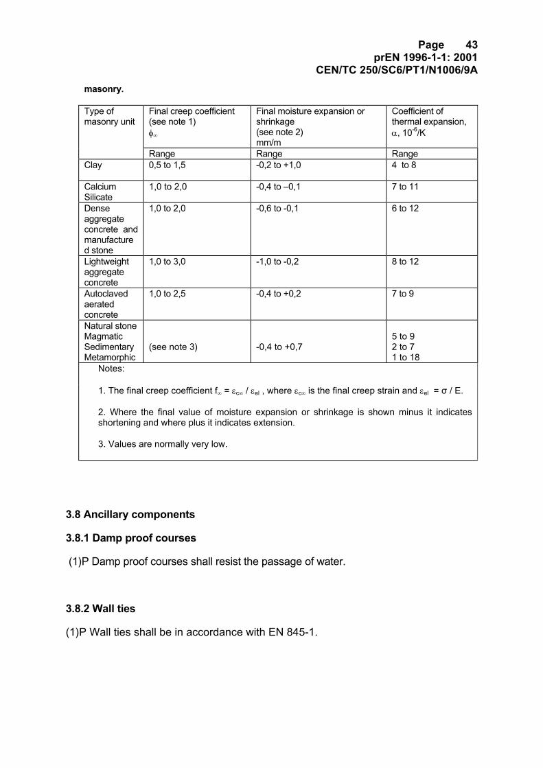
(2) The final creep coefficient, φ∞ , final moisture expansion or shrinkage, or thecoefficient of thermal expansion, α , should be obtained from an evaluation of testdata.
Note: A range of values for the deformation properties of masonry is given in the table below. Thevalues to be used in a particular country should be given in the National Annex.
Range of coefficients of creep, moisture expansion or shrinkage, and thermal properties of
Page 43prEN 1996-1-1: 2001
CEN/TC 250/SC6/PT1/N1006/9Amasonry.
Type ofmasonry unit
Final creep coefficient(see note 1)φ∞
Final moisture expansion orshrinkage(see note 2)mm/m
Coefficient ofthermal expansion,α, 10-6/K
Range Range RangeClay 0,5 to 1,5 -0,2 to +1,0 4 to 8
CalciumSilicate
1,0 to 2,0 -0,4 to –0,1 7 to 11
Denseaggregateconcrete andmanufactured stone
1,0 to 2,0 -0,6 to -0,1 6 to 12
Lightweightaggregateconcrete
1,0 to 3,0 -1,0 to -0,2 8 to 12
Autoclavedaeratedconcrete
1,0 to 2,5 -0,4 to +0,2 7 to 9
Natural stoneMagmaticSedimentaryMetamorphic
(see note 3) -0,4 to +0,75 to 92 to 71 to 18
Notes:
1. The final creep coefficient f∞ = εc∞ / εel , where εc∞ is the final creep strain and εel = σ / E.
2. Where the final value of moisture expansion or shrinkage is shown minus it indicatesshortening and where plus it indicates extension.
3. Values are normally very low.
3.8 Ancillary components
3.8.1 Damp proof courses
(1)P Damp proof courses shall resist the passage of water.
3.8.2 Wall ties
(1)P Wall ties shall be in accordance with EN 845-1.
Page 44prEN 1996-1-1: 2001
CEN/TC 250/SC6/PT1/N1006/9A
3.8.3 Straps, hangers and brackets
(1)P Straps, hangers and brackets shall be in accordance with EN 845-1.
3.8.4 Prefabricated lintels
(1)P Prefabricated lintels shall be in accordance with EN 845-2
3.8.5 Prestressing devices
(1)P Anchorages, couplers, ducts and sheaths shall be in accordance with therequirements of EN 1992-1-1.
Page 45prEN 1996-1-1: 2001
CEN/TC 250/SC6/PT1/N1006/9A
4 Durability4.1 General
(1)P Masonry shall be designed to have adequate durability for its intended use andtaking into account the relevant environmental condition.
4.2 Classification of environmental conditions
4.2.1 Micro conditions of exposure
(1)P The micro conditions to which the masonry is expected to be exposed shall betaken into account in the design.
(2)P When deciding the micro conditions of exposure of the masonry, the effect ofapplied finishes and protective claddings shall be taken into account
(3) Micro conditions of exposure of completed masonry should be categorised intoclasses, as follows:
MX1 - In a dry environment;
MX2 - Exposed to moisture or wetting;
MX3 - Exposed to wetting plus freeze/thaw cycling;
MX4 - Exposed to saturated salt air, seawater or other salt laden water;
MX5 - In an aggressive chemical environment.
Note: When necessary, more closely defined conditions within these classes may be specifiedusing the sub-classes in Annex B (e.g. MX2.1 or MX2.2).
(4) To produce masonry that meets specified performance criteria and withstandsthe environmental conditions to which it is exposed, the determination of theexposure class should take into account:
- climatic factors;
- severity of exposure to wetting;
- exposure to freeze/thaw cycling;
- presence of chemical materials that may lead to damaging reactions.
Page 46prEN 1996-1-1: 2001
CEN/TC 250/SC6/PT1/N1006/9A
4.2.2 Climatic factors (macro conditions of exposure)
(1) The effect of the macro conditions on the micro conditions should be taken intoaccount when determining the relative wetness of masonry and its exposure tofreeze/thaw cycling.
(2) Concerning the macro conditions the following should be taken into account:
- rain and snow;
- the combination of wind and rain;
- temperature variation;
- relative humidity variation.
4.2.3 Exposure to wetness
(1) The exposure to wetness should be taken into account in determining the microconditions of exposure of the masonry. The effect of any applied finishes, cladding,weathered overhanging sills, copings, string courses, drainage or other featuresintended to throw water clear of the masonry should be considered.
Note: It is acknowledged that climates (macro conditions) vary considerably throughout Europeand that certain aspects of climate can influence the risk of exposure of masonry to wetting and/orfreeze/thaw cycling. However, it is the classification of the micro conditions that is relevant fordetermining the durability of masonry rather than the ranking of the macro conditions. Examples ofrelative exposure to wetness of masonry elements in a typical building are given in prEN 1996-2.
4.2.4 Exposure to freeze/thaw cycling
(1) The range and nature of temperature variations should be taken into account indetermining the classification of micro conditions of exposure of the masonry.
4.3 Durability of masonry
4.3.1 Masonry units
(1)P Masonry units shall be sufficiently durable to resist the relevant exposureconditions for the intended life of the building.
Note: Guidance on design and construction to provide adequate durability is given in sections 8 and9 of this EN 1996-1-1 and in EN 1996-2.
Page 47prEN 1996-1-1: 2001
CEN/TC 250/SC6/PT1/N1006/9A
4.3.2 Mortar
(1)P Mortar in masonry shall be sufficiently durable to resist relevant micro exposureconditions for the intended life of the building, and shall not contain constituents whichcan have a detrimental effect on the properties or durability of the mortar or abuttingmaterials.
Note: Guidance on design and construction to achieve adequate durability of mortar joints is given insection 8 of this EN 1996-1-1 and EN 1996-2.
4.3.3 Reinforcing steel
(1)P Reinforcing steel shall be sufficiently durable, either by being corrosion resistant oradequately protected, so that, when placed in accordance with the application rules insection 8, it will resist local exposure conditions for the intended life of the building.
(2) Where carbon steel requires protection to provide adequate durability, it should begalvanised in accordance with EN ISO 1461, such that the zinc coating is not less thanthat required to provide the necessary durability (see (4), below) or the steel should begiven an equivalent protection such as by fusion bonded epoxy powder.
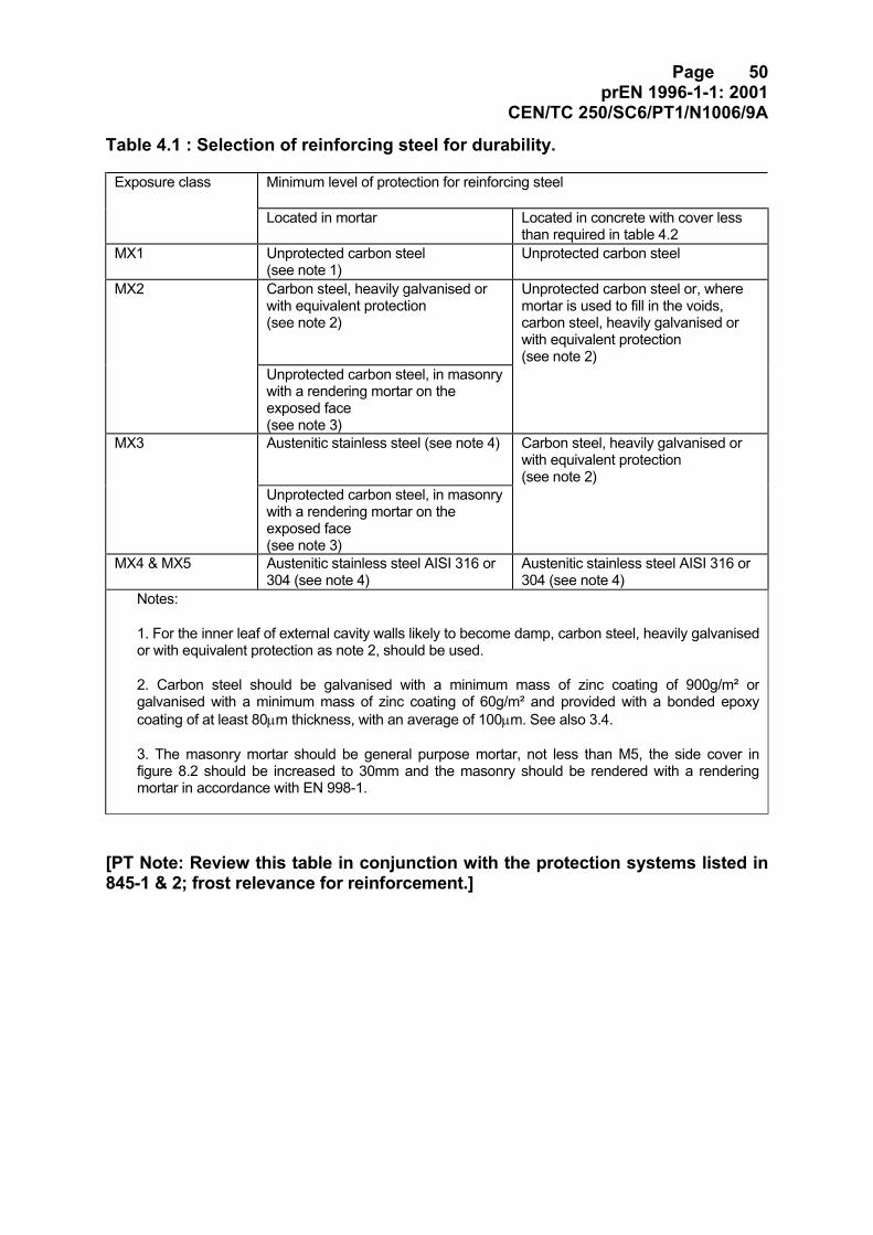
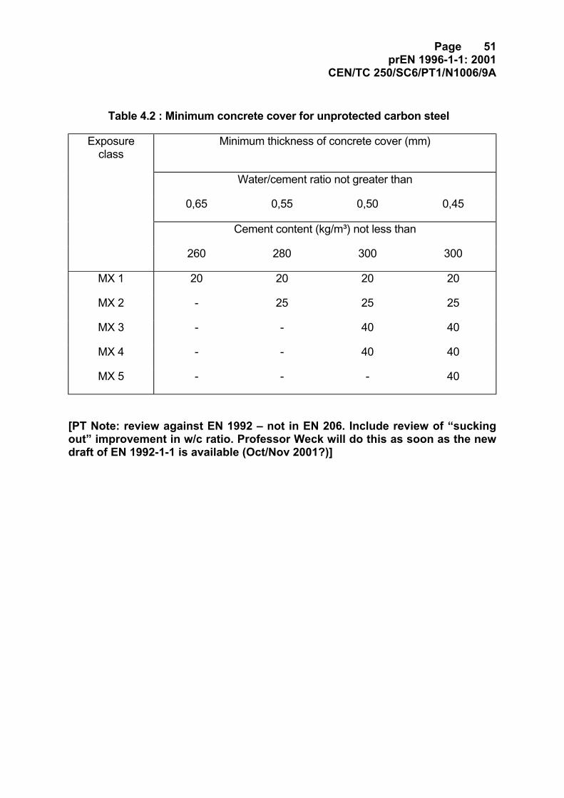
(3) The type of reinforcing steel and the minimum level of protection for the reinforcingsteel that should be used in masonry in the various exposure classes, as defined in 4.2,is given in table 4.1. This table applies to carbon steel, austenitic stainless steel andgalvanised steel when cover to the reinforcing steel is provided in accordance with8.2.4. Alternatively, where unprotected carbon steel is used, it may be protected byconcrete cover in accordance with table 4.2.
(4) Where galvanising is used to provide protection, the reinforcing steel should begalvanised after it has been bent to shape.
(5) For prefabricated bed joint reinforcement, EN 845-3 lists the protection systems thatare to be declared by the manufacturer.
4.3.4 Prestressing steel
(1)P Prestressing steel shall be sufficiently durable, when placed in accordance withthe application rules in section 8, to resist relevant micro exposure conditions for theintended life of the building.
(2) When prestressing steel is to be galvanised it should be of such a composition thatit will not be adversely affected by the galvanising process.
Page 48prEN 1996-1-1: 2001
CEN/TC 250/SC6/PT1/N1006/9A
4.3.5 Damp proof courses
(1)P Damp proof courses shall be durable for the type of building; they shall be formedfrom materials which are not easily punctured in use and they shall be able to resiststresses without exuding.
4.3.6 Wall ties
(1)P Wall ties and their fixings shall be able to withstand the relevant environmentalaction and differential movements between leaves. They shall be corrosion resistant inthe environment in which they are used.
4.3.7 Straps, hangers, brackets and support angles
(1)P Straps, hangers, brackets and support angles shall be corrosion resistant in theenvironmental condition in which they are used.
4.3.8 Prefabricated lintels
(1)P Prefabricated lintels shall be corrosion resistant in the environmental conditionin which they are used.
4.3.9 Prestressing devices
(1)P Anchorages, couplers, ducts and sheaths shall be corrosion resistant in theenvironmental condition in which they are used.
4.4 Masonry below ground
(1)P Masonry below ground shall be such that it is not adversely affected by the groundconditions or it shall be suitably protected therefrom.
(2) Measures should be taken to protect masonry that may be damaged by the effectsof moisture when in contact with the ground.
Page 49prEN 1996-1-1: 2001
CEN/TC 250/SC6/PT1/N1006/9A
(3) When the soil is likely to contain chemicals which might be harmful to themasonry, the masonry should be constructed of materials resistant to the chemicalsor it should be protected in such a way that the aggressive chemicals cannot betransmitted into it.
Page 50prEN 1996-1-1: 2001
CEN/TC 250/SC6/PT1/N1006/9A
Table 4.1 : Selection of reinforcing steel for durability.
Exposure class Minimum level of protection for reinforcing steel
Located in mortar Located in concrete with cover lessthan required in table 4.2
MX1 Unprotected carbon steel(see note 1)
Unprotected carbon steel
MX2 Carbon steel, heavily galvanised orwith equivalent protection(see note 2)
Unprotected carbon steel or, wheremortar is used to fill in the voids,carbon steel, heavily galvanised orwith equivalent protection(see note 2)
Unprotected carbon steel, in masonrywith a rendering mortar on theexposed face(see note 3)
MX3 Austenitic stainless steel (see note 4) Carbon steel, heavily galvanised orwith equivalent protection(see note 2)
Unprotected carbon steel, in masonrywith a rendering mortar on theexposed face(see note 3)
MX4 & MX5 Austenitic stainless steel AISI 316 or304 (see note 4)
Austenitic stainless steel AISI 316 or304 (see note 4)
Notes:
1. For the inner leaf of external cavity walls likely to become damp, carbon steel, heavily galvanisedor with equivalent protection as note 2, should be used.
2. Carbon steel should be galvanised with a minimum mass of zinc coating of 900g/m² orgalvanised with a minimum mass of zinc coating of 60g/m² and provided with a bonded epoxycoating of at least 80µm thickness, with an average of 100µm. See also 3.4.
3. The masonry mortar should be general purpose mortar, not less than M5, the side cover infigure 8.2 should be increased to 30mm and the masonry should be rendered with a renderingmortar in accordance with EN 998-1.
[PT Note: Review this table in conjunction with the protection systems listed in845-1 & 2; frost relevance for reinforcement.]
Page 51prEN 1996-1-1: 2001
CEN/TC 250/SC6/PT1/N1006/9A
Table 4.2 : Minimum concrete cover for unprotected carbon steel
Exposureclass
Minimum thickness of concrete cover (mm)
Water/cement ratio not greater than
0,65 0,55 0,50 0,45
Cement content (kg/m³) not less than
260 280 300 300
MX 1 20 20 20 20
MX 2 - 25 25 25
MX 3 - - 40 40
MX 4 - - 40 40
MX 5 - - - 40
[PT Note: review against EN 1992 – not in EN 206. Include review of “suckingout” improvement in w/c ratio. Professor Weck will do this as soon as the newdraft of EN 1992-1-1 is available (Oct/Nov 2001?)]
Page 52prEN 1996-1-1: 2001
CEN/TC 250/SC6/PT1/N1006/9A
5 Structural analysis5.1 General
(1)P For each relevant limit state verification, a calculation model of the structureshall be set up from:
- an appropriate description of the structure, the materials from which it is made,and the relevant environment of its location;
- the behaviour of the whole or parts of the structure, related to the relevant limitstate;
- the actions and how they are imposed.
(2)P The general arrangement of the structure and the interaction and connection of itsvarious parts shall be such as to give appropriate stability and robustness duringconstruction and use.
(3) Calculation models may be based on separate parts of the structure (such aswalls) independently, provided that 5.1(2)P is satisfied.
Note: Where the structure is made of separately designed components the overall stability androbustness should be ensured.
(4) The response of the structure should be calculated using either
− non linear theory of elasticity assuming a relationship between stress and strain (see3.7.1)
or
− linear theory of elasticity assuming a linear relationship between stress and strain witha slope equal to the short term secant modulus of elasticity (see 3.7.2).
(5) The results obtained from analysis of the calculation models should provide, in anymember,
- the axial loads due to vertical loading
- the shear loads due to vertical and/or horizontal loading
- the eccentricity of the axial loads
- the bending moments due to vertical or lateral loading
(6)P Structural members shall be verified in the ultimate limit state and the serviceabilitylimit state, using, as actions the results obtained from the analysis.
Page 53prEN 1996-1-1: 2001
CEN/TC 250/SC6/PT1/N1006/9A
(7) Design rules for verification in the ultimate limit state and the serviceability limit stateare given in Sections 6 and 7.
5.2 Structural behaviour in accidental situations (other than earthquakes andfire)
(1)P In addition to designing the structure to support loads arising from normal use, itshall be ensured that there is a reasonable probability that it will not be damagedunder the effect of misuse or accident to an extent disproportionate to the originalcause.
Note: no structure can be expected to be resistant to the excessive loads or forces, or loss ofbearing members or portions of the structure, that could arise due to an extreme cause. Forexample in a small building the primary damage may cause total destruction.
(2) The structural behaviour under accidental situations should be considered usingone of the following methods:
- members designed to resist the effects of accidental actions given in EN 1991-1-7
- the hypothetical removal of essential loadbearing members in turn, with specialattention being paid to the integrity of ties and restraints to members;
- reducing the risk of accidental actions, such as the use of impact barriers againstvehicle impact.
5.3 Imperfections
(1)P The possible effects of imperfections shall be allowed for by assuming that thestructure is inclined at an angle υ = 1/(100 √ htot) radians to the vertical,
where:
htot is the total height of the structure in metres.
The resulting horizontal action shall be added to the other actions.
5.4 Second order effects
(1)P Structures incorporating masonry walls designed according to this EN 1996-1-1shall have their parts braced together adequately so that sway of the structure iseither prevented or allowed for by calculation.
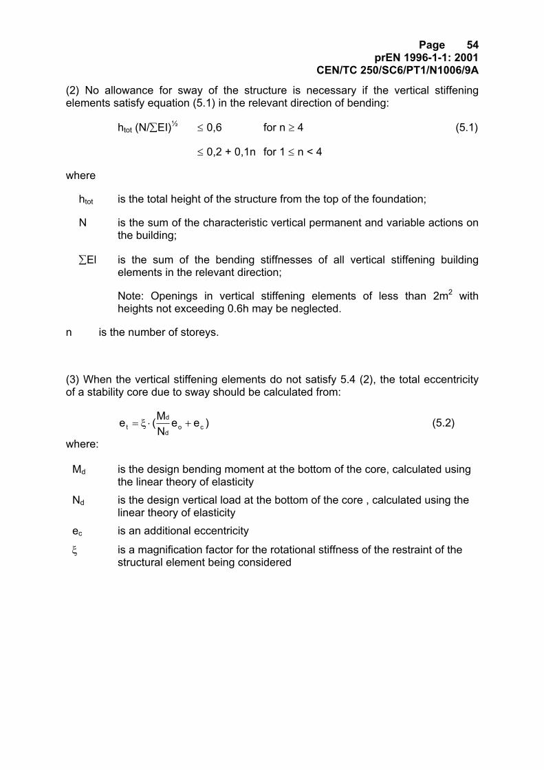
Page 54prEN 1996-1-1: 2001
CEN/TC 250/SC6/PT1/N1006/9A
(2) No allowance for sway of the structure is necessary if the vertical stiffeningelements satisfy equation (5.1) in the relevant direction of bending:
htot (N/∑EI)½ ≤ 0,6 for n ≥ 4 (5.1)
≤ 0,2 + 0,1n for 1 ≤ n < 4
where
htot is the total height of the structure from the top of the foundation;
N is the sum of the characteristic vertical permanent and variable actions onthe building;
∑El is the sum of the bending stiffnesses of all vertical stiffening buildingelements in the relevant direction;
Note: Openings in vertical stiffening elements of less than 2m2 withheights not exceeding 0.6h may be neglected.
n is the number of storeys.
(3) When the vertical stiffening elements do not satisfy 5.4 (2), the total eccentricityof a stability core due to sway should be calculated from:
)eeNM(e co
d
dt +⋅ξ= (5.2)
where:
Md is the design bending moment at the bottom of the core, calculated usingthe linear theory of elasticity
Nd is the design vertical load at the bottom of the core , calculated using thelinear theory of elasticity
ec is an additional eccentricity
ξ is a magnification factor for the rotational stiffness of the restraint of thestructural element being considered
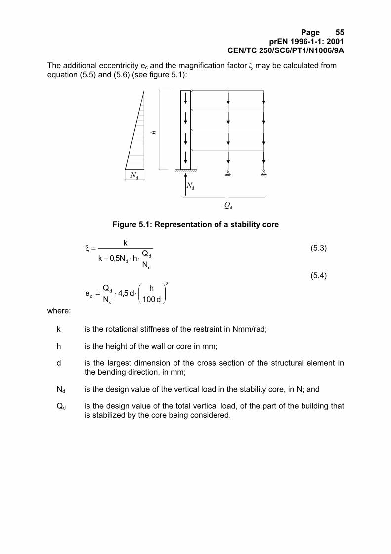
Page 55prEN 1996-1-1: 2001
CEN/TC 250/SC6/PT1/N1006/9A
The additional eccentricity ec and the magnification factor ξ may be calculated fromequation (5.5) and (5.6) (see figure 5.1):
Nd
h
Nd
Qd
Figure 5.1: Representation of a stability core
d
dd N
QhN5,0k
k
⋅⋅−=ξ (5.3)
(5.4)
2
d
dc d100
hd5,4NQe
⋅⋅=
where:
k is the rotational stiffness of the restraint in Nmm/rad;
h is the height of the wall or core in mm;
d is the largest dimension of the cross section of the structural element inthe bending direction, in mm;
Nd is the design value of the vertical load in the stability core, in N; and
Qd is the design value of the total vertical load, of the part of the building thatis stabilized by the core being considered.
Page 56prEN 1996-1-1: 2001
CEN/TC 250/SC6/PT1/N1006/9A
5.5 Analysis of structural members
5.5.1 Masonry walls subjected to vertical loading
(1) When analysing walls subjected to vertical loading, allowance in the designshould be made for the following:
- vertical loads directly applied to the wall;
- second order effects;
- eccentricities calculated from a knowledge of the layout of the walls, theinteraction of the floors and the stiffening walls;
- eccentricities resulting from construction deviations and differences in the materialproperties of individual components.
(2) The bending moments may be calculated from the material properties given inSection 3, the joint behaviour, and from the principles of structural mechanics.
Note: A simplified method for calculating the bending moments in walls due to vertical loading is givenin Annex C.
(3)P An accidental eccentricity, ea , shall be assumed for the full height of a wall to allow for constructionimperfections.
(4) The accidental eccentricity, ea , may be assumed to be hef / 450, where hef is theeffective height of the wall, calculated from 6.1.4.
5.5.2 Reinforced masonry members subjected to vertical loading
5.5.2.1 Effective span of masonry beams
(1) The effective span, lef , of simply supported or continuous masonry beams, with theexception of deep beams, may be taken as the smaller of the following:
- the distance between centres of supports;
- the clear distance between supports plus the effective depth, d.
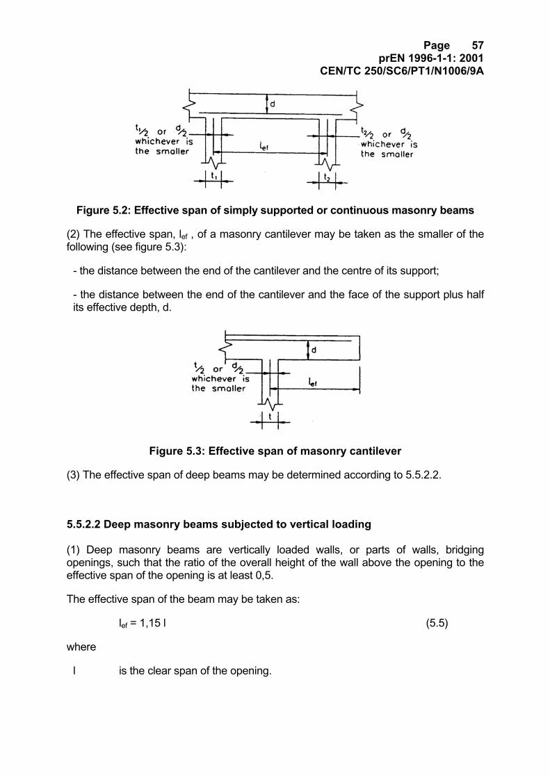
Page 57prEN 1996-1-1: 2001
CEN/TC 250/SC6/PT1/N1006/9A
Figure 5.2: Effective span of simply supported or continuous masonry beams
(2) The effective span, lef , of a masonry cantilever may be taken as the smaller of thefollowing (see figure 5.3):
- the distance between the end of the cantilever and the centre of its support;
- the distance between the end of the cantilever and the face of the support plus halfits effective depth, d.
Figure 5.3: Effective span of masonry cantilever
(3) The effective span of deep beams may be determined according to 5.5.2.2.
5.5.2.2 Deep masonry beams subjected to vertical loading
(1) Deep masonry beams are vertically loaded walls, or parts of walls, bridgingopenings, such that the ratio of the overall height of the wall above the opening to theeffective span of the opening is at least 0,5.
The effective span of the beam may be taken as:
lef = 1,15 l (5.5)
where
l is the clear span of the opening.
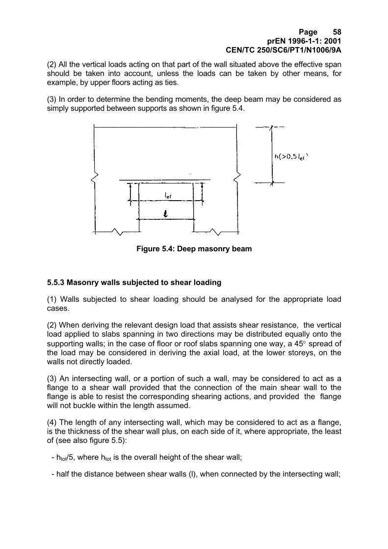
Page 58prEN 1996-1-1: 2001
CEN/TC 250/SC6/PT1/N1006/9A
(2) All the vertical loads acting on that part of the wall situated above the effective spanshould be taken into account, unless the loads can be taken by other means, forexample, by upper floors acting as ties.
(3) In order to determine the bending moments, the deep beam may be considered assimply supported between supports as shown in figure 5.4.
Figure 5.4: Deep masonry beam
5.5.3 Masonry walls subjected to shear loading
(1) Walls subjected to shear loading should be analysed for the appropriate loadcases.
(2) When deriving the relevant design load that assists shear resistance, the verticalload applied to slabs spanning in two directions may be distributed equally onto thesupporting walls; in the case of floor or roof slabs spanning one way, a 45° spread ofthe load may be considered in deriving the axial load, at the lower storeys, on thewalls not directly loaded.
(3) An intersecting wall, or a portion of such a wall, may be considered to act as aflange to a shear wall provided that the connection of the main shear wall to theflange is able to resist the corresponding shearing actions, and provided the flangewill not buckle within the length assumed.
(4) The length of any intersecting wall, which may be considered to act as a flange,is the thickness of the shear wall plus, on each side of it, where appropriate, the leastof (see also figure 5.5):
- htot/5, where htot is the overall height of the shear wall;
- half the distance between shear walls (l), when connected by the intersecting wall;
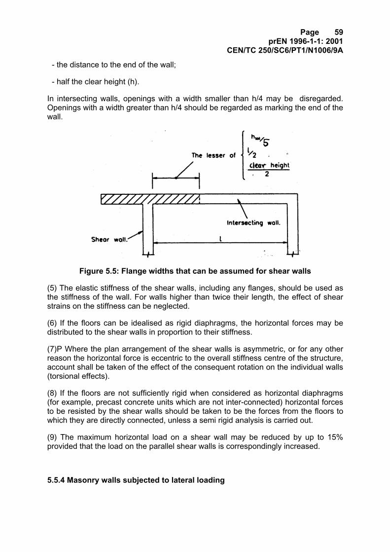
Page 59prEN 1996-1-1: 2001
CEN/TC 250/SC6/PT1/N1006/9A
- the distance to the end of the wall;
- half the clear height (h).
In intersecting walls, openings with a width smaller than h/4 may be disregarded.Openings with a width greater than h/4 should be regarded as marking the end of thewall.
Figure 5.5: Flange widths that can be assumed for shear walls
(5) The elastic stiffness of the shear walls, including any flanges, should be used asthe stiffness of the wall. For walls higher than twice their length, the effect of shearstrains on the stiffness can be neglected.
(6) If the floors can be idealised as rigid diaphragms, the horizontal forces may bedistributed to the shear walls in proportion to their stiffness.
(7)P Where the plan arrangement of the shear walls is asymmetric, or for any otherreason the horizontal force is eccentric to the overall stiffness centre of the structure,account shall be taken of the effect of the consequent rotation on the individual walls(torsional effects).
(8) If the floors are not sufficiently rigid when considered as horizontal diaphragms(for example, precast concrete units which are not inter-connected) horizontal forcesto be resisted by the shear walls should be taken to be the forces from the floors towhich they are directly connected, unless a semi rigid analysis is carried out.
(9) The maximum horizontal load on a shear wall may be reduced by up to 15%provided that the load on the parallel shear walls is correspondingly increased.
5.5.4 Masonry walls subjected to lateral loading
Page 60prEN 1996-1-1: 2001
CEN/TC 250/SC6/PT1/N1006/9A
[PT Note: Clause temporarily removed to Part -1-3.]
Page 61prEN 1996-1-1: 2001
CEN/TC 250/SC6/PT1/N1006/9A
6 Ultimate Limit State
6.1 Unreinforced masonry walls subjected to mainly vertical loading
6.1.1 General
(1)P The resistance of masonry walls to vertical loading shall be based on the geometryof the wall, the effect of the applied eccentricities and the material properties of themasonry.
(2) In calculating the vertical resistance of masonry walls, it may be assumed that:
- plane sections remain plane;
- the tensile strength of masonry perpendicular to bed joints is zero;
6.1.2 Verification of unreinforced masonry walls subjected to mainly verticalloading
(1)P At the ultimate limit state, the design value of the vertical load applied to amasonry wall, NSd , shall be less than or equal to the design value of the verticalresistance of the wall, NRd , such that:
NSd ≤ NRd (6.1)
(2) The design value of the vertical resistance of a single leaf wall per unit length,NRd, is given by:
NRd = Φ t fd (6.2)
where:
Φ is the capacity reduction factor, Φi , at the top or bottom of the wall, or Φm ,in the middle of the wall, as appropriate, allowing for the effects ofslenderness and eccentricity of loading, obtained from 6.1.3.
t is the thickness of the wall;
fd is the design compressive strength of the masonry, obtained from 3.6.1.X.
(3) Where the cross-sectional area of a wall is less than 0,1 m2, the designcompressive strength of the masonry, fd, should be multiplied by the factor:
(0,7 + 3 A) (6.3)
where:
Page 62prEN 1996-1-1: 2001
CEN/TC 250/SC6/PT1/N1006/9A
A is the loaded horizontal gross cross-sectional area of the wall, expressedin square metres.
(4) For cavity walls, each leaf should be verified separately, using the plan area of theloaded leaf and the slenderness ratio based upon the effective thickness of the cavitywall, calculated according to equation (6.15).
(5) A faced wall, should be designed in the same manner as a single-leaf wallconstructed entirely of the weaker units, using the value of K, from Table 3.4,appropriate to a wall with a longitudinal mortar joint.
(6) A double-leaf wall tied together according to clause 6.3.3 may be designed as asingle-leaf wall, if both leaves have a load of similar magnitude, or, alternatively, as acavity wall.
(7) When chases or recesses are outside the limits given in clause 8.6, the effect onloadbearing capacity should be taken into account as follows:
- vertical chases or recesses should be treated either as a wall end or, alternatively,the residual thickness of the wall should be used in the calculations of the designvertical load resistance;
- horizontal or inclined chases should be treated by verifying the strength of the wallat the chase position, taking account of the load eccentricity.
Note: As a general guide the reduction in vertical loadbearing capacity may be taken to beproportional to the reduction in cross-sectional area due to any vertical chase or recess, providedthat the reduction in area does not exceed 25%.
6.1.3 Reduction factor for slenderness and eccentricity
(1) The value of the reduction factor for slenderness and eccentricity, Φ, may beobtained as follows:
(i) At the top or bottom of the wall (Φi)
te 2 - 1 = i
iΦ (6.4)
where:
ei is the eccentricity at the top or the bottom of the wall, as appropriate,calculated using the equation (6.5):
0,05t e + e + NM = e ahi
id
id i ≥ (6.5)
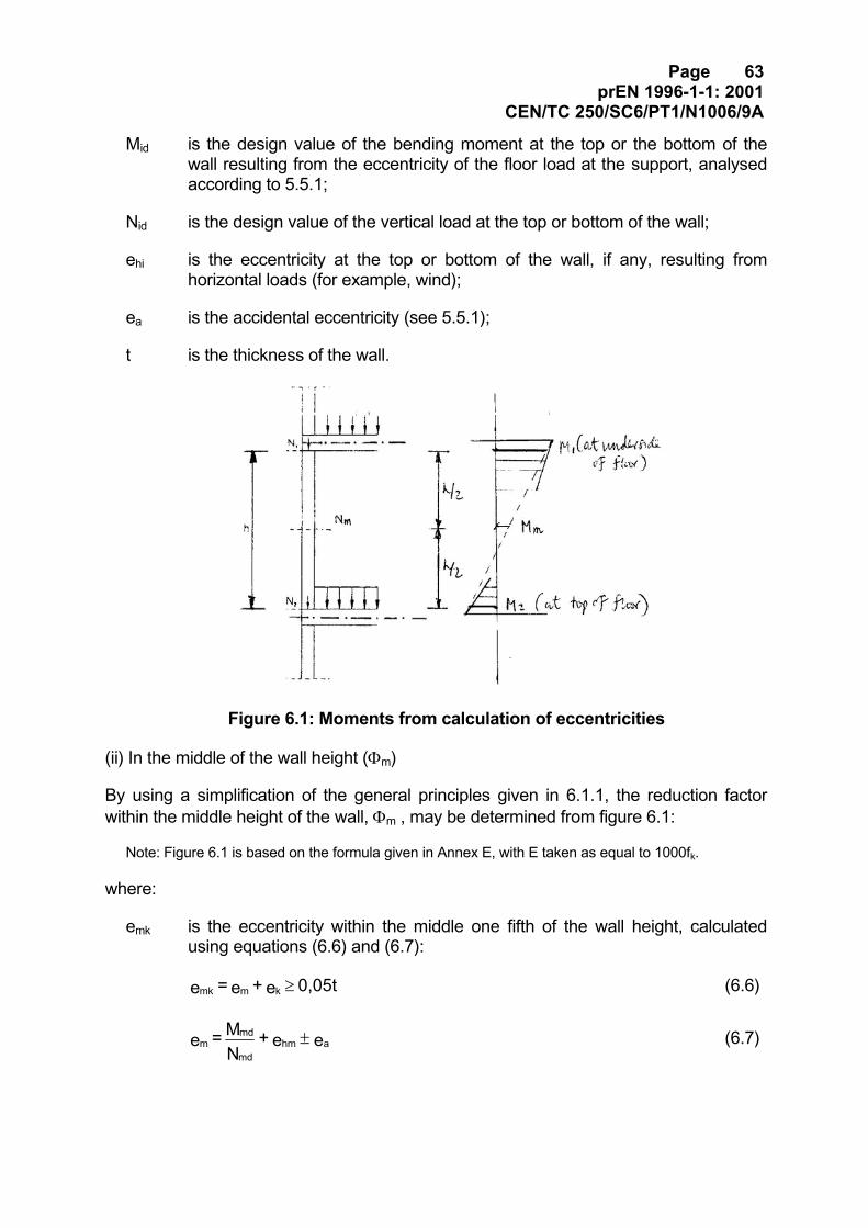
Page 63prEN 1996-1-1: 2001
CEN/TC 250/SC6/PT1/N1006/9A
Mid is the design value of the bending moment at the top or the bottom of thewall resulting from the eccentricity of the floor load at the support, analysedaccording to 5.5.1;
Nid is the design value of the vertical load at the top or bottom of the wall;
ehi is the eccentricity at the top or bottom of the wall, if any, resulting fromhorizontal loads (for example, wind);
ea is the accidental eccentricity (see 5.5.1);
t is the thickness of the wall.
Figure 6.1: Moments from calculation of eccentricities
(ii) In the middle of the wall height (Φm)
By using a simplification of the general principles given in 6.1.1, the reduction factorwithin the middle height of the wall, Φm , may be determined from figure 6.1:
Note: Figure 6.1 is based on the formula given in Annex E, with E taken as equal to 1000fk.
where:
emk is the eccentricity within the middle one fifth of the wall height, calculatedusing equations (6.6) and (6.7):
0,05t e + e = e kmmk ≥ (6.6)
e e + NM = e ahm
md
mdm ± (6.7)
Page 64prEN 1996-1-1: 2001
CEN/TC 250/SC6/PT1/N1006/9A
em is the eccentricity due to loads;
Mmd is the design value of the greatest moment in the middle of the height of thewall resulting from the moments at the top and bottom of the wall (see figure6.1);
Nmd is the design value of the vertical load at the middle of the height of the wall;
ehm is the eccentricity at mid-height resulting from horizontal loads (for example,wind);
Note: the inclusion of ehm depends on the load combination being used for the verification.
hef is the effective height, obtained from 6.1.4 for the appropriate restraint orstiffening condition;
tef is the effective thickness of the wall, obtained from 6.1.5;
ek is the eccentricity due to creep, calculated from the equation (6.8):
e t th 0,002 = e m
ef
efk ∞φ (6.8)
φ∞ is the final creep coefficient (see note under 3.7.4(2))
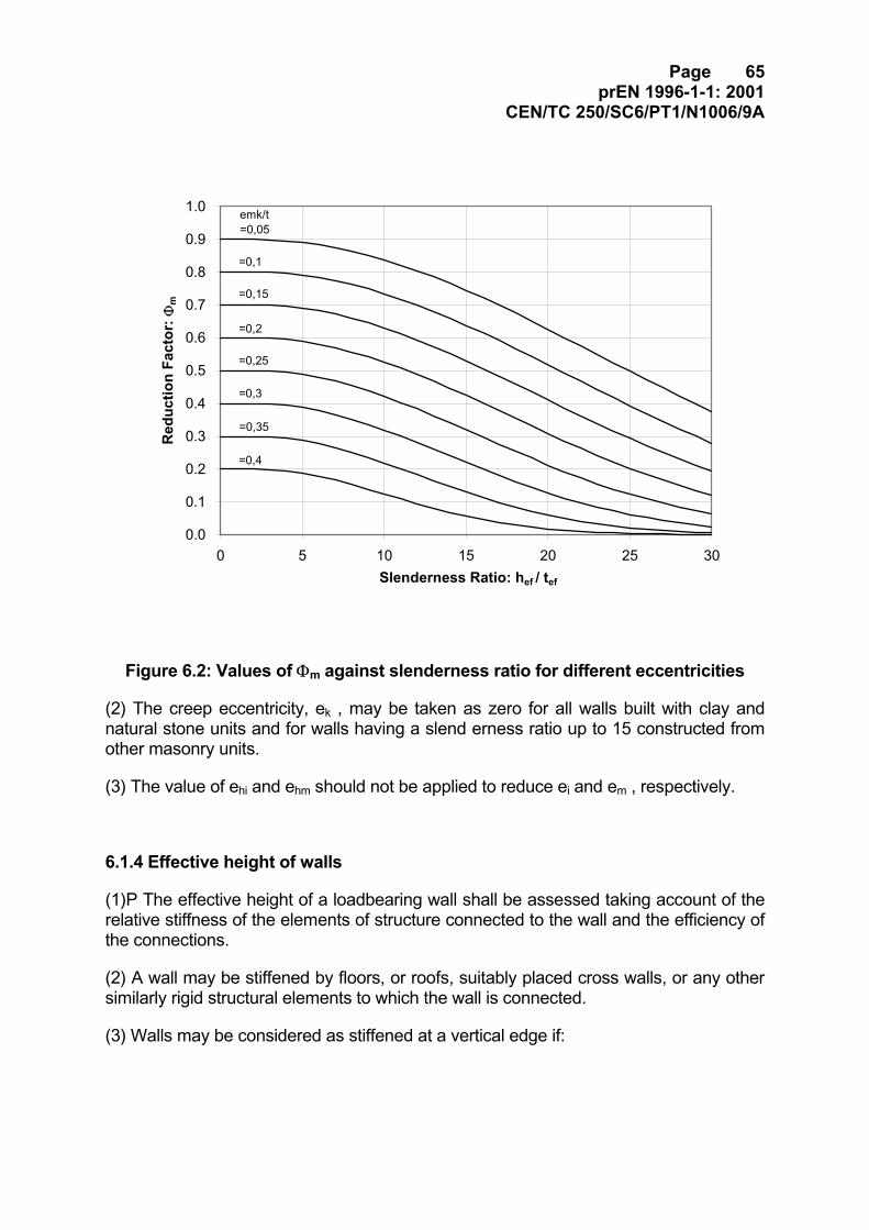
Page 65prEN 1996-1-1: 2001
CEN/TC 250/SC6/PT1/N1006/9A
0.0
0.1
0.2
0.3
0.4
0.5
0.6
0.7
0.8
0.9
1.0
0 5 10 15 20 25 30Slenderness Ratio: hef / tef
Red
uctio
n Fa
ctor
: Φm
emk/t=0,05
=0,15
=0,1
=0,2
=0,25
=0,3
=0,35
=0,4
Figure 6.2: Values of Φm against slenderness ratio for different eccentricities
(2) The creep eccentricity, ek , may be taken as zero for all walls built with clay andnatural stone units and for walls having a slend erness ratio up to 15 constructed fromother masonry units.
(3) The value of ehi and ehm should not be applied to reduce ei and em , respectively.
6.1.4 Effective height of walls
(1)P The effective height of a loadbearing wall shall be assessed taking account of therelative stiffness of the elements of structure connected to the wall and the efficiency ofthe connections.
(2) A wall may be stiffened by floors, or roofs, suitably placed cross walls, or any othersimilarly rigid structural elements to which the wall is connected.
(3) Walls may be considered as stiffened at a vertical edge if:
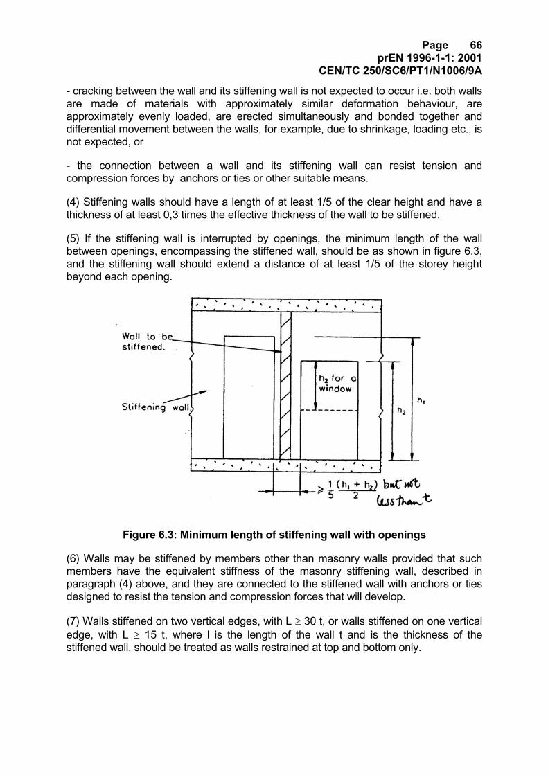
Page 66prEN 1996-1-1: 2001
CEN/TC 250/SC6/PT1/N1006/9A
- cracking between the wall and its stiffening wall is not expected to occur i.e. both wallsare made of materials with approximately similar deformation behaviour, areapproximately evenly loaded, are erected simultaneously and bonded together anddifferential movement between the walls, for example, due to shrinkage, loading etc., isnot expected, or
- the connection between a wall and its stiffening wall can resist tension andcompression forces by anchors or ties or other suitable means.
(4) Stiffening walls should have a length of at least 1/5 of the clear height and have athickness of at least 0,3 times the effective thickness of the wall to be stiffened.
(5) If the stiffening wall is interrupted by openings, the minimum length of the wallbetween openings, encompassing the stiffened wall, should be as shown in figure 6.3,and the stiffening wall should extend a distance of at least 1/5 of the storey heightbeyond each opening.
Figure 6.3: Minimum length of stiffening wall with openings
(6) Walls may be stiffened by members other than masonry walls provided that suchmembers have the equivalent stiffness of the masonry stiffening wall, described inparagraph (4) above, and they are connected to the stiffened wall with anchors or tiesdesigned to resist the tension and compression forces that will develop.
(7) Walls stiffened on two vertical edges, with L ≥ 30 t, or walls stiffened on one verticaledge, with L ≥ 15 t, where l is the length of the wall t and is the thickness of thestiffened wall, should be treated as walls restrained at top and bottom only.
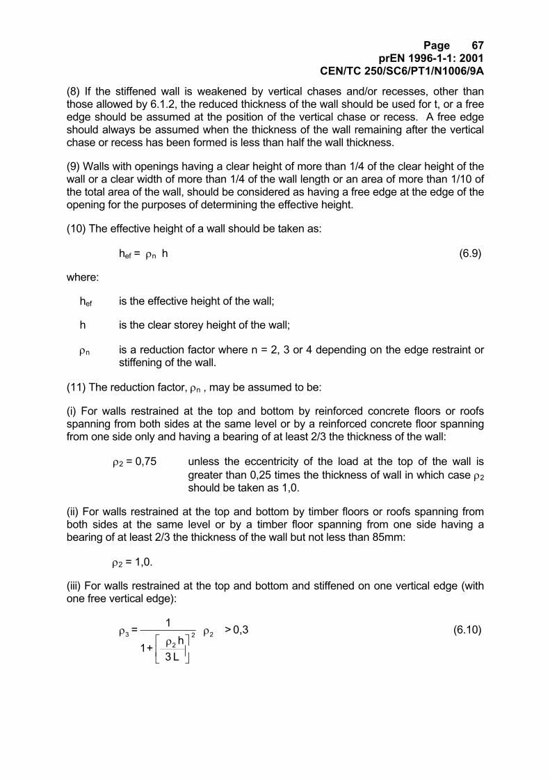
Page 67prEN 1996-1-1: 2001
CEN/TC 250/SC6/PT1/N1006/9A
(8) If the stiffened wall is weakened by vertical chases and/or recesses, other thanthose allowed by 6.1.2, the reduced thickness of the wall should be used for t, or a freeedge should be assumed at the position of the vertical chase or recess. A free edgeshould always be assumed when the thickness of the wall remaining after the verticalchase or recess has been formed is less than half the wall thickness.
(9) Walls with openings having a clear height of more than 1/4 of the clear height of thewall or a clear width of more than 1/4 of the wall length or an area of more than 1/10 ofthe total area of the wall, should be considered as having a free edge at the edge of theopening for the purposes of determining the effective height.
(10) The effective height of a wall should be taken as:
hef = ρn h (6.9)
where:
hef is the effective height of the wall;
h is the clear storey height of the wall;
ρn is a reduction factor where n = 2, 3 or 4 depending on the edge restraint orstiffening of the wall.
(11) The reduction factor, ρn , may be assumed to be:
(i) For walls restrained at the top and bottom by reinforced concrete floors or roofsspanning from both sides at the same level or by a reinforced concrete floor spanningfrom one side only and having a bearing of at least 2/3 the thickness of the wall:
ρ2 = 0,75 unless the eccentricity of the load at the top of the wall isgreater than 0,25 times the thickness of wall in which case ρ2should be taken as 1,0.
(ii) For walls restrained at the top and bottom by timber floors or roofs spanning fromboth sides at the same level or by a timber floor spanning from one side having abearing of at least 2/3 the thickness of the wall but not less than 85mm:
ρ2 = 1,0.
(iii) For walls restrained at the top and bottom and stiffened on one vertical edge (withone free vertical edge):
0,3 >
L 3h
+ 1
1 = 22
2 3 ρ
ρρ (6.10)
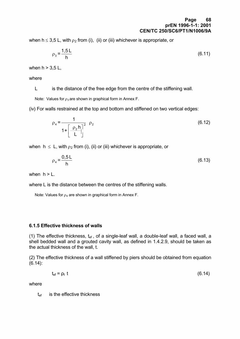
Page 68prEN 1996-1-1: 2001
CEN/TC 250/SC6/PT1/N1006/9A
when h ≤ 3,5 L, with ρ2 from (i), (ii) or (iii) whichever is appropriate, or
hL 1,5 = 3ρ (6.11)
when h > 3,5 L,
where
L is the distance of the free edge from the centre of the stiffening wall.
Note: Values for ρ3 are shown in graphical form in Annex F.
(iv) For walls restrained at the top and bottom and stiffened on two vertical edges:
ρ
ρρ 2
22 4
Lh
+ 1
1 = (6.12)
when h ≤ L, with ρ2 from (i), (ii) or (iii) whichever is appropriate, or
hL 0,5 = 4ρ (6.13)
when h > L.
where L is the distance between the centres of the stiffening walls.
Note: Values for ρ4 are shown in graphical form in Annex F.
6.1.5 Effective thickness of walls
(1) The effective thickness, tef , of a single-leaf wall, a double-leaf wall, a faced wall, ashell bedded wall and a grouted cavity wall, as defined in 1.4.2.9, should be taken asthe actual thickness of the wall, t.
(2) The effective thickness of a wall stiffened by piers should be obtained from equation(6.14):
tef = ρt t (6.14)
where
tef is the effective thickness
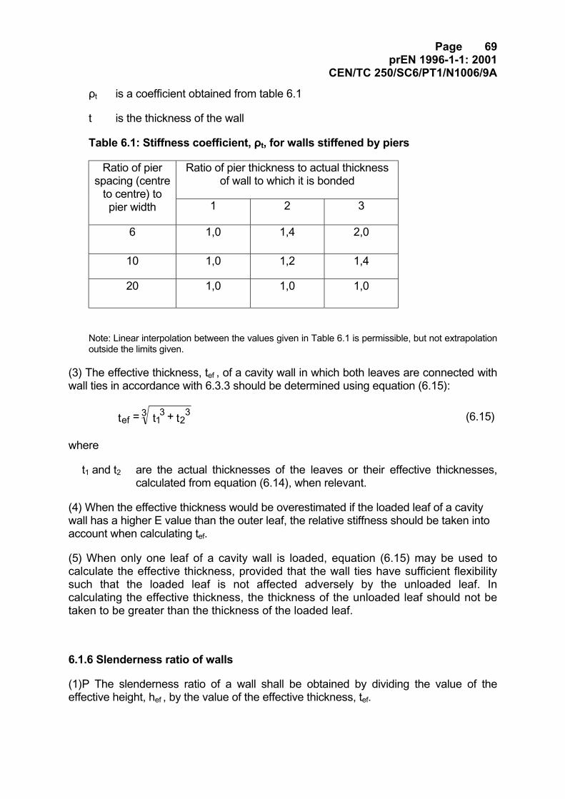
Page 69prEN 1996-1-1: 2001
CEN/TC 250/SC6/PT1/N1006/9A
ρt is a coefficient obtained from table 6.1
t is the thickness of the wall
Table 6.1: Stiffness coefficient, ρt, for walls stiffened by piers
Ratio of pier thickness to actual thicknessof wall to which it is bonded
Ratio of pierspacing (centre
to centre) topier width 1 2 3
6 1,0 1,4 2,0
10 1,0 1,2 1,4
20 1,0 1,0 1,0
Note: Linear interpolation between the values given in Table 6.1 is permissible, but not extrapolationoutside the limits given.
(3) The effective thickness, tef , of a cavity wall in which both leaves are connected withwall ties in accordance with 6.3.3 should be determined using equation (6.15):
323
13
ef t + t = t (6.15)
where
t1 and t2 are the actual thicknesses of the leaves or their effective thicknesses,calculated from equation (6.14), when relevant.
(4) When the effective thickness would be overestimated if the loaded leaf of a cavitywall has a higher E value than the outer leaf, the relative stiffness should be taken intoaccount when calculating tef.
(5) When only one leaf of a cavity wall is loaded, equation (6.15) may be used tocalculate the effective thickness, provided that the wall ties have sufficient flexibilitysuch that the loaded leaf is not affected adversely by the unloaded leaf. Incalculating the effective thickness, the thickness of the unloaded leaf should not betaken to be greater than the thickness of the loaded leaf.
6.1.6 Slenderness ratio of walls
(1)P The slenderness ratio of a wall shall be obtained by dividing the value of theeffective height, hef , by the value of the effective thickness, tef.
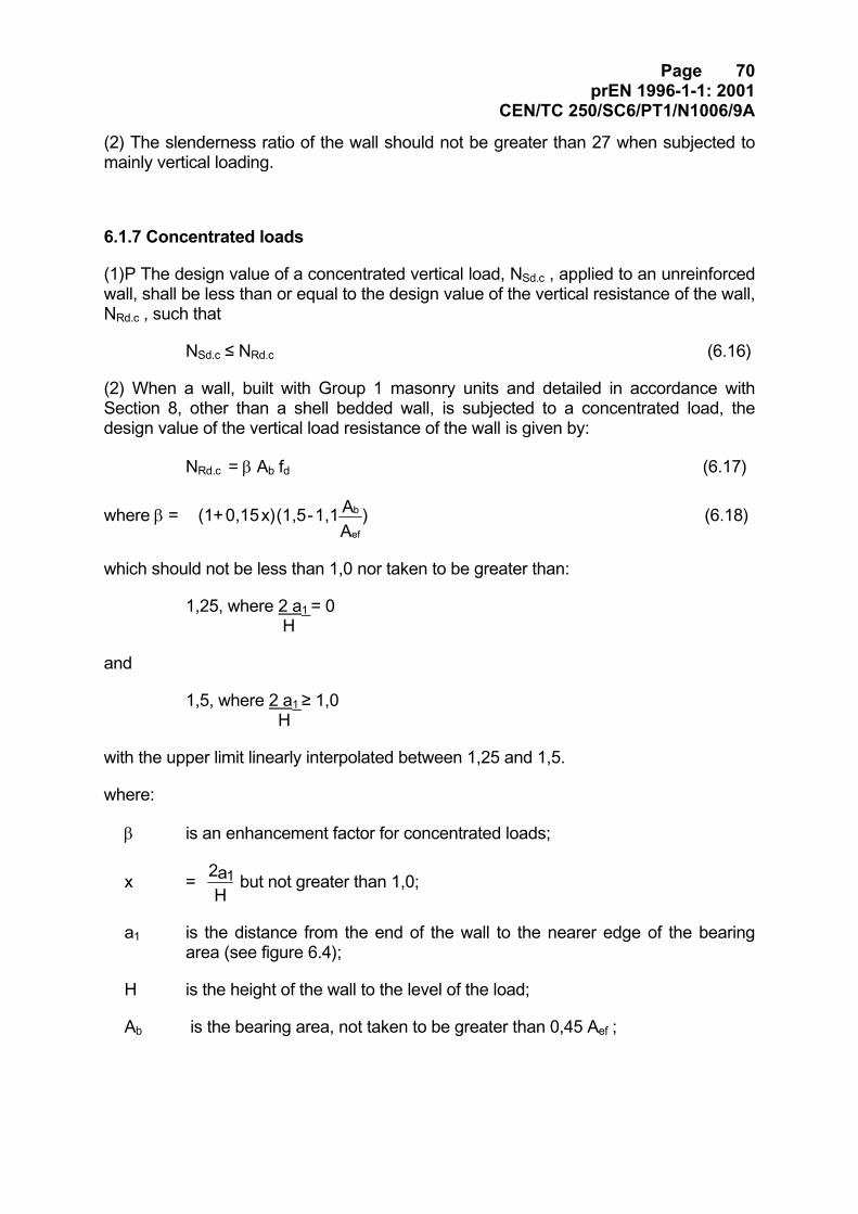
Page 70prEN 1996-1-1: 2001
CEN/TC 250/SC6/PT1/N1006/9A
(2) The slenderness ratio of the wall should not be greater than 27 when subjected tomainly vertical loading.
6.1.7 Concentrated loads
(1)P The design value of a concentrated vertical load, NSd.c , applied to an unreinforcedwall, shall be less than or equal to the design value of the vertical resistance of the wall,NRd.c , such that
NSd.c ≤ NRd.c (6.16)
(2) When a wall, built with Group 1 masonry units and detailed in accordance withSection 8, other than a shell bedded wall, is subjected to a concentrated load, thedesign value of the vertical load resistance of the wall is given by:
NRd.c = β Ab fd (6.17)
where β = )AA 1,1 - (1,5 x)0,15 + (1
ef
b (6.18)
which should not be less than 1,0 nor taken to be greater than:
1,25, where 2 a1 = 0 H
and
1,5, where 2 a1 ≥ 1,0 H
with the upper limit linearly interpolated between 1,25 and 1,5.
where:
β is an enhancement factor for concentrated loads;
x = Ha2 1 but not greater than 1,0;
a1 is the distance from the end of the wall to the nearer edge of the bearingarea (see figure 6.4);
H is the height of the wall to the level of the load;
Ab is the bearing area, not taken to be greater than 0,45 Aef ;
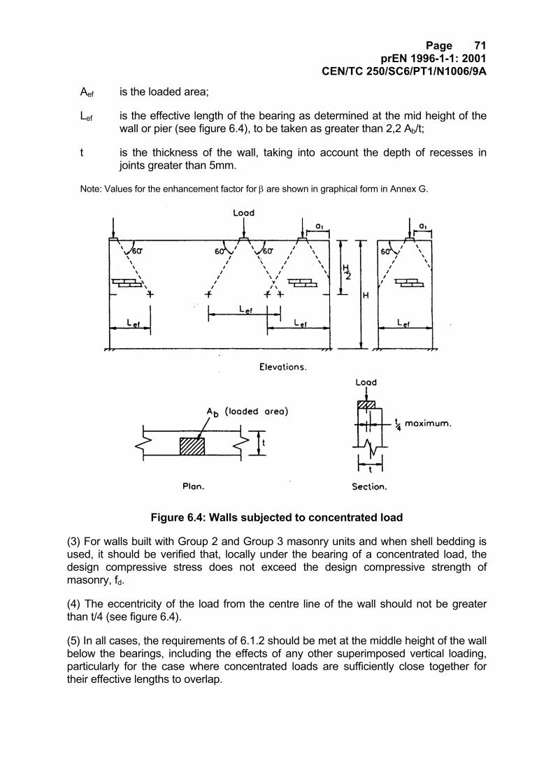
Page 71prEN 1996-1-1: 2001
CEN/TC 250/SC6/PT1/N1006/9A
Aef is the loaded area;
Lef is the effective length of the bearing as determined at the mid height of thewall or pier (see figure 6.4), to be taken as greater than 2,2 Ab/t;
t is the thickness of the wall, taking into account the depth of recesses injoints greater than 5mm.
Note: Values for the enhancement factor for β are shown in graphical form in Annex G.
Figure 6.4: Walls subjected to concentrated load
(3) For walls built with Group 2 and Group 3 masonry units and when shell bedding isused, it should be verified that, locally under the bearing of a concentrated load, thedesign compressive stress does not exceed the design compressive strength ofmasonry, fd.
(4) The eccentricity of the load from the centre line of the wall should not be greaterthan t/4 (see figure 6.4).
(5) In all cases, the requirements of 6.1.2 should be met at the middle height of the wallbelow the bearings, including the effects of any other superimposed vertical loading,particularly for the case where concentrated loads are sufficiently close together fortheir effective lengths to overlap.
Page 72prEN 1996-1-1: 2001
CEN/TC 250/SC6/PT1/N1006/9A
(6) The concentrated load should bear on a Group 1 unit or other solid material oflength equal to the required bearing length plus a length on each side of the bearingbased on a 60° spread of load to the base of the solid material; for an end bearing theadditional length is required on one side only.
(7) Where the concentrated load is applied through a spreader beam of adequatestiffness and of width t , height greater than 200mm and length greater than three timesthe bearing length of the load, the design value of the compressive stress beneath theconcentrated load should not exceed 1,5 fd.
6.2 Unreinforced masonry subjected to shear loading
6.2.1 General
(1)P At the ultimate limit state the design value of the shear load applied to themasonry wall, VSd , shall be less than or equal to the design value of the shearresistance of the wall, VRd , such that :
VSd ≤ VRd (6.19)
(2) The design value of the shear resistance is given by:
VRd = fvd t lc (6.20)
where:
fvd is the design value of the shear strength of masonry, obtained from 3.6.2,based on the vertical load being resisted by the compressed part of the wall,ignoring any part of the wall that is in tension;
t is the thickness of the wall;
lc is the length of the compressed part of the wall, ignoring any part of the wallthat is in tension;
(3) The distribution of shear stress along a wall may be assumed to be constant.
(4) The length of the compressed part of the wall, lc , should be calculated assuming atriangular or trapezoidal stress distribution, and taking into account any openings,chases or recesses; any portion of the wall subjected to vertical tensile stresses shouldnot be used in calculating the area of the wall to resist shear.
(5)P The connections between shear walls and flanges of intersecting walls shall beverified for vertical shear.
Page 73prEN 1996-1-1: 2001
CEN/TC 250/SC6/PT1/N1006/9A
(6) The vertical shear resistance of a connection may be obtained from suitable testsfor a specific project or it may be taken from an evaluation of test data. In the absenceof such data, the characteristic vertical shear resistance may be based on fvko , wherefvko is the shear strength under zero compressive stress, as given in 3.6.2, andprovided that the connection between the walls is in accordance with 8.5.2.1.
(7) The length of the compressed part of the wall should be verified for the verticalloading applied to it and the vertical load effect of the shear loads.
6.3 Unreinforced masonry: walls subjected to lateral loading
[PT Note: Temporarily removed to Part 1-3. This also affects the equationnumbering system for the remainder of this section.]
[Start of PT Note:
In answer to the Danish request for a further method of dealing with verticaland horizontal loads, the following clause is being considered:
6.4 Unreinforced masonry walls subjected to combined vertical and lateralloading
6.4.1 General
(1) Unreinforced masonry walls that are subjected to both vertical and lateral loadingmay be verified by using any one of the methods given in 6.4.2, 6.4.3 or 6.4.4, asappropriate.
6.4.2 Method using Φ factor
(1) By using the relevant value of the eccentricity due to horizontal action, ehi or ehm ,a slenderness reduction factor that takes into account the combined vertical andhorizontal loading can be obtained, using equations 6.5 and 6.7, for use in equation6.2.
6.4.3 Method using apparent fxk1
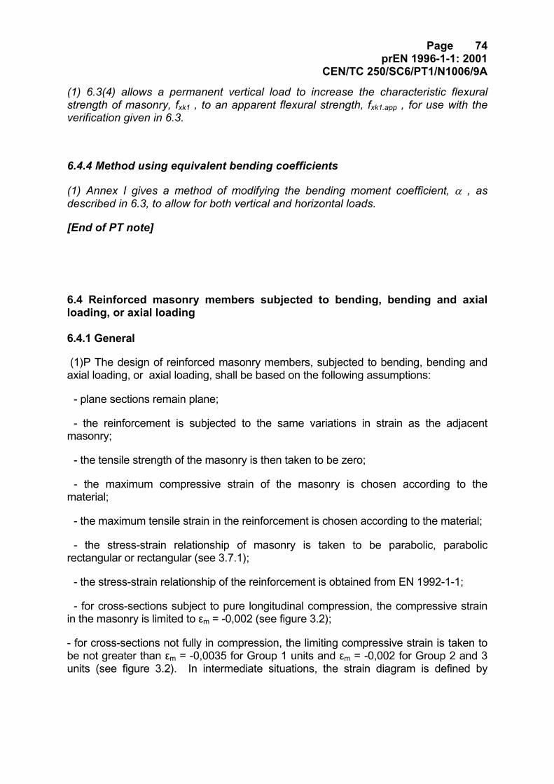
Page 74prEN 1996-1-1: 2001
CEN/TC 250/SC6/PT1/N1006/9A
(1) 6.3(4) allows a permanent vertical load to increase the characteristic flexuralstrength of masonry, fxk1 , to an apparent flexural strength, fxk1.app , for use with theverification given in 6.3.
6.4.4 Method using equivalent bending coefficients
(1) Annex I gives a method of modifying the bending moment coefficient, α , asdescribed in 6.3, to allow for both vertical and horizontal loads.
[End of PT note]
6.4 Reinforced masonry members subjected to bending, bending and axialloading, or axial loading
6.4.1 General
(1)P The design of reinforced masonry members, subjected to bending, bending andaxial loading, or axial loading, shall be based on the following assumptions:
- plane sections remain plane;
- the reinforcement is subjected to the same variations in strain as the adjacentmasonry;
- the tensile strength of the masonry is then taken to be zero;
- the maximum compressive strain of the masonry is chosen according to thematerial;
- the maximum tensile strain in the reinforcement is chosen according to the material;
- the stress-strain relationship of masonry is taken to be parabolic, parabolicrectangular or rectangular (see 3.7.1);
- the stress-strain relationship of the reinforcement is obtained from EN 1992-1-1;
- for cross-sections subject to pure longitudinal compression, the compressive strainin the masonry is limited to εm = -0,002 (see figure 3.2);
- for cross-sections not fully in compression, the limiting compressive strain is taken tobe not greater than εm = -0,0035 for Group 1 units and εm = -0,002 for Group 2 and 3units (see figure 3.2). In intermediate situations, the strain diagram is defined by
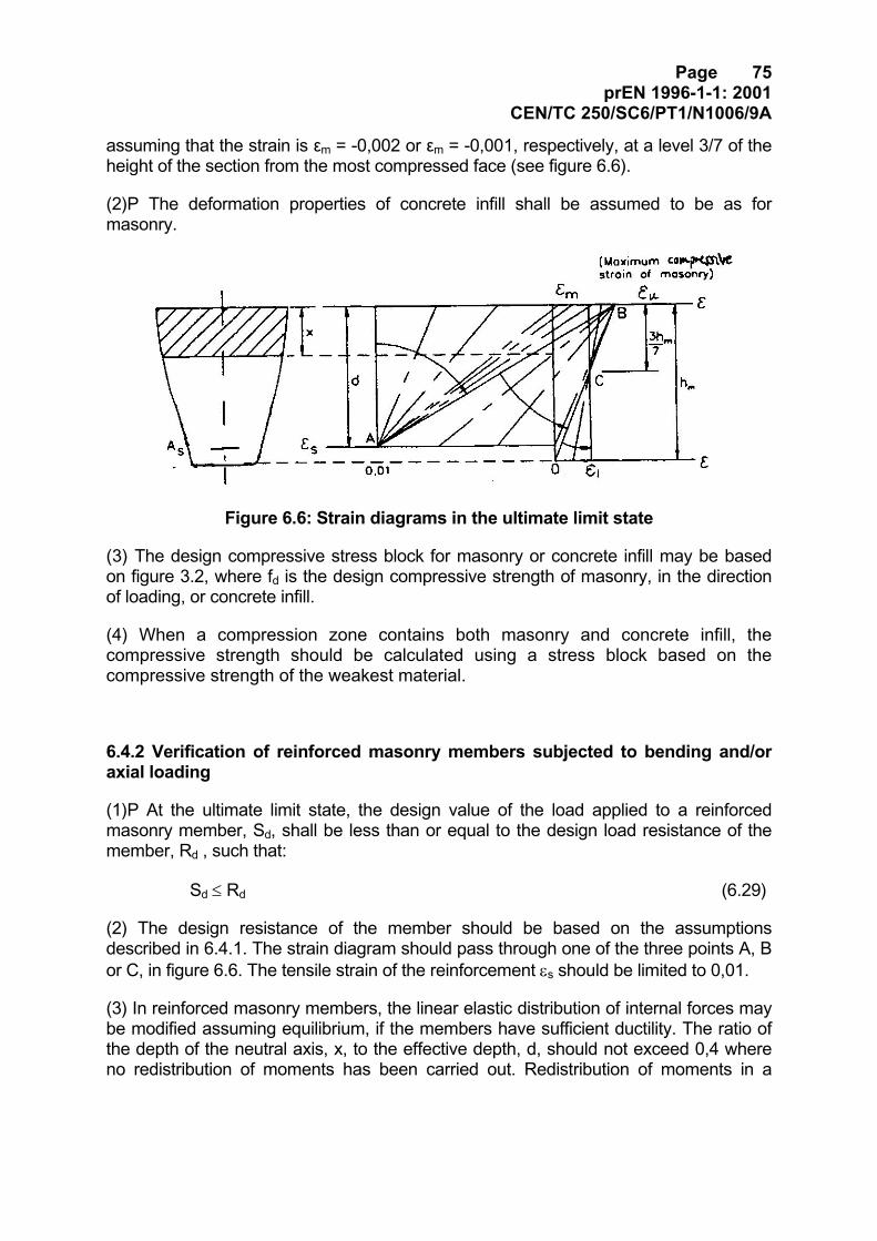
Page 75prEN 1996-1-1: 2001
CEN/TC 250/SC6/PT1/N1006/9A
assuming that the strain is εm = -0,002 or εm = -0,001, respectively, at a level 3/7 of theheight of the section from the most compressed face (see figure 6.6).
(2)P The deformation properties of concrete infill shall be assumed to be as formasonry.
Figure 6.6: Strain diagrams in the ultimate limit state
(3) The design compressive stress block for masonry or concrete infill may be basedon figure 3.2, where fd is the design compressive strength of masonry, in the directionof loading, or concrete infill.
(4) When a compression zone contains both masonry and concrete infill, thecompressive strength should be calculated using a stress block based on thecompressive strength of the weakest material.
6.4.2 Verification of reinforced masonry members subjected to bending and/oraxial loading
(1)P At the ultimate limit state, the design value of the load applied to a reinforcedmasonry member, Sd, shall be less than or equal to the design load resistance of themember, Rd , such that:
Sd ≤ Rd (6.29)
(2) The design resistance of the member should be based on the assumptionsdescribed in 6.4.1. The strain diagram should pass through one of the three points A, Bor C, in figure 6.6. The tensile strain of the reinforcement εs should be limited to 0,01.
(3) In reinforced masonry members, the linear elastic distribution of internal forces maybe modified assuming equilibrium, if the members have sufficient ductility. The ratio ofthe depth of the neutral axis, x, to the effective depth, d, should not exceed 0,4 whereno redistribution of moments has been carried out. Redistribution of moments in a
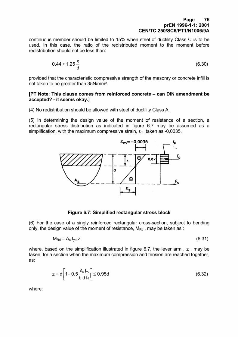
Page 76prEN 1996-1-1: 2001
CEN/TC 250/SC6/PT1/N1006/9A
continuous member should be limited to 15% when steel of ductility Class C is to beused. In this case, the ratio of the redistributed moment to the moment beforeredistribution should not be less than:
dx 1,25 + 0,44 (6.30)
provided that the characteristic compressive strength of the masonry or concrete infill isnot taken to be greater than 35N/mm².
[PT Note: This clause comes from reinforced concrete – can DIN amendment beaccepted? - it seems okay.]
(4) No redistribution should be allowed with steel of ductility Class A.
(5) In determining the design value of the moment of resistance of a section, arectangular stress distribution as indicated in figure 6.7 may be assumed as asimplification, with the maximum compressive strain, εm ,taken as -0,0035.
Figure 6.7: Simplified rectangular stress block
(6) For the case of a singly reinforced rectangular cross-section, subject to bendingonly, the design value of the moment of resistance, MRd , may be taken as :
MRd = As fyd z (6.31)
where, based on the simplification illustrated in figure 6.7, the lever arm , z , may betaken, for a section when the maximum compression and tension are reached together,as:
0,95df d bfA0,51 dz
d
yd s≤
−= (6.32)
where:
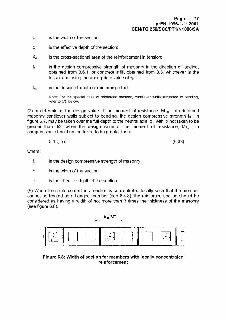
Page 77prEN 1996-1-1: 2001
CEN/TC 250/SC6/PT1/N1006/9A
b is the width of the section;
d is the effective depth of the section;
As is the cross-sectional area of the reinforcement in tension;
fd is the design compressive strength of masonry in the direction of loading,obtained from 3.6.1, or concrete infill, obtained from 3.3, whichever is thelesser and using the appropriate value of γM;
fyd is the design strength of reinforcing steel;
Note: For the special case of reinforced masonry cantilever walls subjected to bending,refer to (7), below.
(7) In determining the design value of the moment of resistance, MRd , of reinforcedmasonry cantilever walls subject to bending, the design compressive strength fd , infigure 6.7, may be taken over the full depth to the neutral axis, x , with x not taken to begreater than d/2, when the design value of the moment of resistance, MRd , incompression, should not be taken to be greater than:
0,4 fd b d2 (6.33)
where:
fd is the design compressive strength of masonry;
b is the width of the section;
d is the effective depth of the section.
(8) When the reinforcement in a section is concentrated locally such that the membercannot be treated as a flanged member (see 6.4.3), the reinforced section should beconsidered as having a width of not more than 3 times the thickness of the masonry(see figure 6.8).
Figure 6.8: Width of section for members with locally concentratedreinforcement
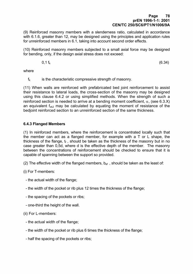
Page 78prEN 1996-1-1: 2001
CEN/TC 250/SC6/PT1/N1006/9A
(9) Reinforced masonry members with a slenderness ratio, calculated in accordancewith 6.1.6, greater than 12, may be designed using the principles and application rulesfor unreinforced members in 6.1, taking into account second order effects.
(10) Reinforced masonry members subjected to a small axial force may be designedfor bending, only, if the design axial stress does not exceed:
0,1 fk (6.34)
where
fk is the characteristic compressive strength of masonry.
(11) When walls are reinforced with prefabricated bed joint reinforcement to assisttheir resistance to lateral loads, the cross-section of the masonry may be designedusing this clause 6.4.2 or using simplified methods. When the strength of such areinforced section is needed to arrive at a bending moment coefficient, α, (see 6.3.X)an equivalent fxk2 may be calculated by equating the moment of resistance of thebedjoint reinforced section to an unreinforced section of the same thickness.
6.4.3 Flanged Members
(1) In reinforced members, where the reinforcement is concentrated locally such thatthe member can act as a flanged member, for example with a T or L shape, thethickness of the flange, tf , should be taken as the thickness of the masonry but in nocase greater than 0,5d, where d is the effective depth of the member. The masonrybetween the concentrations of reinforcement should be checked to ensure that it iscapable of spanning between the support so provided.
(2) The effective width of the flanged members, bef , should be taken as the least of:
(i) For T-members:
- the actual width of the flange;
- the width of the pocket or rib plus 12 times the thickness of the flange;
- the spacing of the pockets or ribs;
- one-third the height of the wall.
(ii) For L-members:
- the actual width of the flange;
- the width of the pocket or rib plus 6 times the thickness of the flange;
- half the spacing of the pockets or ribs;
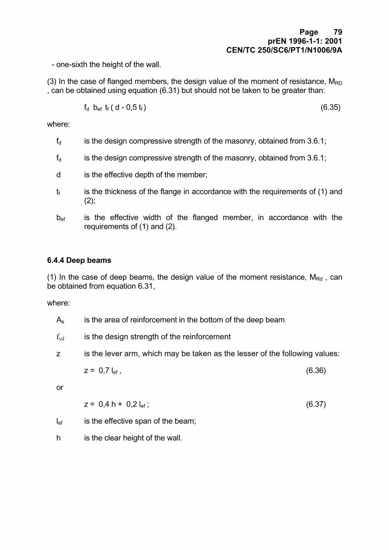
Page 79prEN 1996-1-1: 2001
CEN/TC 250/SC6/PT1/N1006/9A
- one-sixth the height of the wall.
(3) In the case of flanged members, the design value of the moment of resistance, MRD, can be obtained using equation (6.31) but should not be taken to be greater than:
fd bef tf ( d - 0,5 tf ) (6.35)
where:
fd is the design compressive strength of the masonry, obtained from 3.6.1;
fd is the design compressive strength of the masonry, obtained from 3.6.1;
d is the effective depth of the member;
tf is the thickness of the flange in accordance with the requirements of (1) and(2);
bef is the effective width of the flanged member, in accordance with therequirements of (1) and (2).
6.4.4 Deep beams
(1) In the case of deep beams, the design value of the moment resistance, MRd , canbe obtained from equation 6.31,
where:
As is the area of reinforcement in the bottom of the deep beam
fyd is the design strength of the reinforcement
z is the lever arm, which may be taken as the lesser of the following values:
z = 0,7 lef , (6.36)
or
z = 0,4 h + 0,2 lef ; (6.37)
lef is the effective span of the beam;
h is the clear height of the wall.
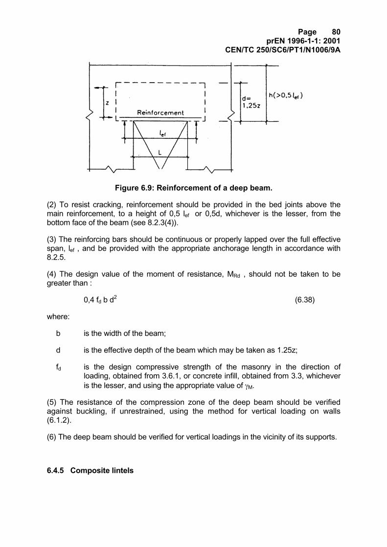
Page 80prEN 1996-1-1: 2001
CEN/TC 250/SC6/PT1/N1006/9A
Figure 6.9: Reinforcement of a deep beam.
(2) To resist cracking, reinforcement should be provided in the bed joints above themain reinforcement, to a height of 0,5 lef or 0,5d, whichever is the lesser, from thebottom face of the beam (see 8.2.3(4)).
(3) The reinforcing bars should be continuous or properly lapped over the full effectivespan, lef , and be provided with the appropriate anchorage length in accordance with8.2.5.
(4) The design value of the moment of resistance, MRd , should not be taken to begreater than :
0,4 fd b d2 (6.38)
where:
b is the width of the beam;
d is the effective depth of the beam which may be taken as 1.25z;
fd is the design compressive strength of the masonry in the direction ofloading, obtained from 3.6.1, or concrete infill, obtained from 3.3, whicheveris the lesser, and using the appropriate value of γM.
(5) The resistance of the compression zone of the deep beam should be verifiedagainst buckling, if unrestrained, using the method for vertical loading on walls(6.1.2).
(6) The deep beam should be verified for vertical loadings in the vicinity of its supports.
6.4.5 Composite lintels
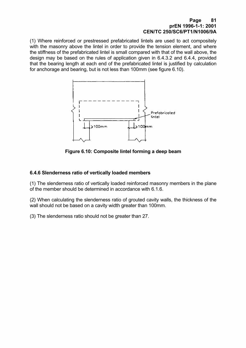
Page 81prEN 1996-1-1: 2001
CEN/TC 250/SC6/PT1/N1006/9A
(1) Where reinforced or prestressed prefabricated lintels are used to act compositelywith the masonry above the lintel in order to provide the tension element, and wherethe stiffness of the prefabricated lintel is small compared with that of the wall above, thedesign may be based on the rules of application given in 6.4.3.2 and 6.4.4, providedthat the bearing length at each end of the prefabricated lintel is justified by calculationfor anchorage and bearing, but is not less than 100mm (see figure 6.10).
Figure 6.10: Composite lintel forming a deep beam
6.4.6 Slenderness ratio of vertically loaded members
(1) The slenderness ratio of vertically loaded reinforced masonry members in the planeof the member should be determined in accordance with 6.1.6.
(2) When calculating the slenderness ratio of grouted cavity walls, the thickness of thewall should not be based on a cavity width greater than 100mm.
(3) The slenderness ratio should not be greater than 27.
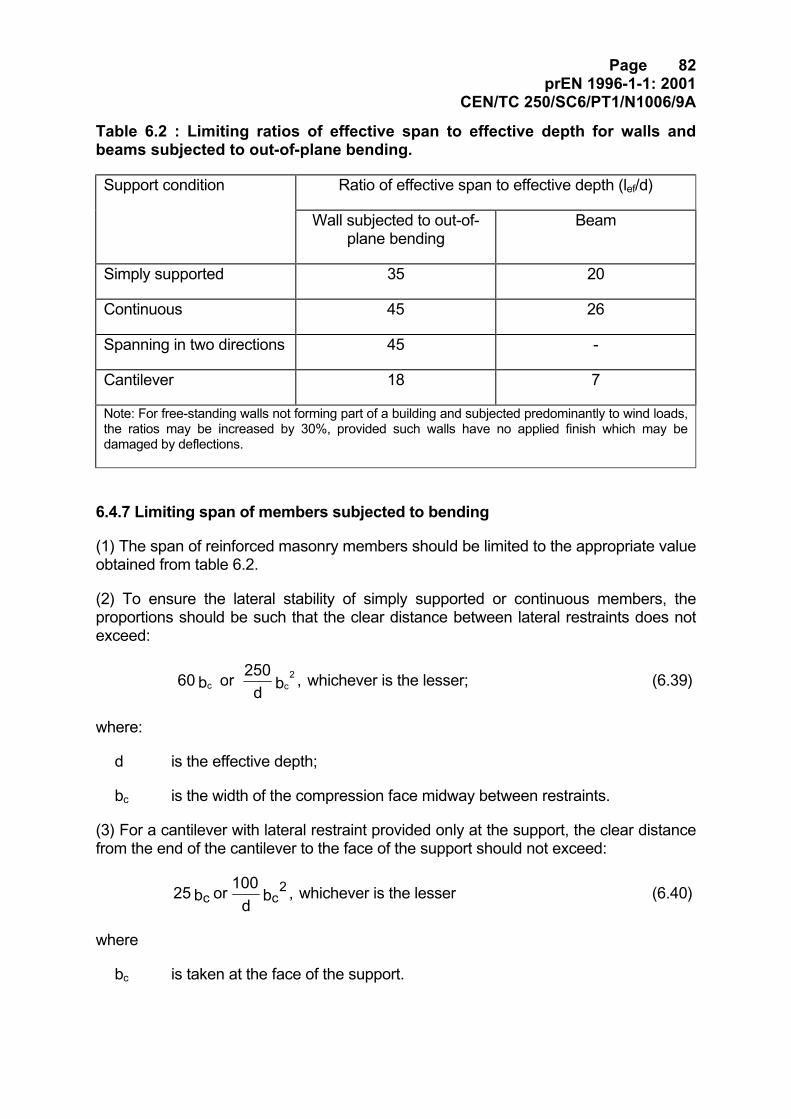
Page 82prEN 1996-1-1: 2001
CEN/TC 250/SC6/PT1/N1006/9A
Table 6.2 : Limiting ratios of effective span to effective depth for walls andbeams subjected to out-of-plane bending.
Support condition Ratio of effective span to effective depth (lef/d)
Wall subjected to out-of-plane bending
Beam
Simply supported 35 20
Continuous 45 26
Spanning in two directions 45 -
Cantilever 18 7
Note: For free-standing walls not forming part of a building and subjected predominantly to wind loads,the ratios may be increased by 30%, provided such walls have no applied finish which may bedamaged by deflections.
6.4.7 Limiting span of members subjected to bending
(1) The span of reinforced masonry members should be limited to the appropriate valueobtained from table 6.2.
(2) To ensure the lateral stability of simply supported or continuous members, theproportions should be such that the clear distance between lateral restraints does notexceed:
, b d250 or b 60 c
2c whichever is the lesser; (6.39)
where:
d is the effective depth;
bc is the width of the compression face midway between restraints.
(3) For a cantilever with lateral restraint provided only at the support, the clear distancefrom the end of the cantilever to the face of the support should not exceed:
, b d100 or b 25 c
2c whichever is the lesser (6.40)
where
bc is taken at the face of the support.
Page 83prEN 1996-1-1: 2001
CEN/TC 250/SC6/PT1/N1006/9A
6.5 Reinforced masonry: members subjected to shear loading
6.5.1 General
(1)P At the ultimate limit state the design shear load applied to a reinforced masonrymember, VSd , shall be less than or equal to the design shear resistance of themember, VRd , such that:
VSd ≤ VRd (6.41)
(2) In calculating the design shear load on members with uniformly distributed loading,it may be assumed that the maximum shear load occurs at a distance d/2 from the faceof a support, where d is the effective depth of the member.
(3) When taking the maximum shear load at d/2 from the face of a support, thefollowing conditions should be satisfied:
- the loading and support reactions are such that they cause diagonal compression inthe member (direct support);
- at an end support, the tension reinforcement required at a distance 2,5d from theface of the support is anchored into the support;
- at an intermediate support, the tension reinforcement required at the face of thesupport extends for a distance at least 2,5d, plus the anchorage length, into the span.
(4) The design shear resistance of reinforced masonry members, VRd , may becalculated either by:
- ignoring the contribution of any shear reinforcement incorporated into the member,where the minimum area of shear reinforcement, as required by 8.2.3, is not provided,
or
- taking into account the contribution of the shear reinforcement, where at least theminimum area of shear reinforcement is provided.
(5) The extent of any contribution of concrete infill to the shear resistance of thereinforced masonry member should be considered, and, where the concrete infillmakes a much greater contribution to the shear resistance than the masonry, EN 1992-1-1 should be used and the strength of the masonry should be ignored.
[PT Note: Add in here the possibility of getting shear resistance from tensionsteel, 17.5ρ (UK 4.7.2.2(1).]
Page 84prEN 1996-1-1: 2001
CEN/TC 250/SC6/PT1/N1006/9A
6.5.2 Verification of reinforced masonry walls subjected to horizontal loads in theplane of the wall
(1) For reinforced masonry walls, when the contribution of any shear reinforcement isbeing ignored, it should be verified that:
VSd ≤ VRd1 (6.42)
and V Rd1 = fvd t L (6.43)
where:
VSd is the design value of the applied horizontal load
t is the thickness of the wall;
L is the length of the wall;
fvd is the design shear strength of masonry, obtained from 3.6.2, or concreteinfill, obtained from 3.3, whichever is the lesser.
Note: Where appropriate, an enhancement in the design shear strength, fvd, may be taken intoaccount in the calculation of V Rd1 to allow for the presence of vertical reinforcement.
(2) For reinforced masonry walls, when horizontal shear reinforcement is taken intoaccount, it should be verified that:
VSd ≤ VRd1 + VRd2 (6.44)
where:
VRd1 is given by equation (6.43), and
VRd2 is given by:
L f s
A = V ydsw
Rd2 (6.45)
where:
L is the length of the wall;
Asw is the area of horizontal shear reinforcement;
s is the vertical spacing of horizontal shear reinforcement;
fyd is the design strength of the reinforcing steel;
(3) Where shear reinforcement enhancement is used it should also be verified that:
Page 85prEN 1996-1-1: 2001
CEN/TC 250/SC6/PT1/N1006/9A
0,2≤+L tVV Rd2Rd1 (6.46)
where:
t is the thickness of the wall;
L is the length of the wall;
6.5.3 Verification of reinforced masonry beams subjected to shear loading
(1) For reinforced masonry beams when the contribution of any shear reinforcement isbeing ignored, it should be verified that:
VSd ≤ VRd1 (6.47)
and VRd1 = fvd b d (6.48)
where:
VSd is the design value of the applied shear load
b is the minimum width of the beam over the effective depth;
d is the effective depth of the beam; for deep beams d should be taken as1.25 z, where z is defined in 6.4.4
fvd is the design shear strength of masonry, obtained from 3.6.2, or concreteinfill, obtained from 3.3, whichever is the lesser, using the appropriatevalue of γM;
Note: Where required, an enhancement in the design shear strength, fvd , may be taken into accountin the calculation of VRd1 to allow for the presence of longitudinal reinforcement.
(2) The value of fvd for use in determining VRd1, at a section aV from the face of asupport, may be increased by a factor :
4 a2d
V≤ (6.49)
where:
d is the effective depth of the beam;
aV is the distance from the face of the support to the cross-section beingconsidered;
Page 86prEN 1996-1-1: 2001
CEN/TC 250/SC6/PT1/N1006/9A
provided fvk is not taken to be greater than 0,7 N/mm².
(3) For masonry beams when shear reinforcement is taken into account, it should beverified that:
VSd ≤ VRd1 + VRd2 (6.50)
where:
VRd1 is given by equation (6.46) and
VRd2 is given by:
sin ) cot + (1 f s
A d 0,9 = V ydsw
Rd2 αα (6.51)
where:
d is the effective depth of the beam;
Asw is the area of shear reinforcement;
s is the spacing of shear reinforcement;
α is the angle of shear reinforcement to the axis of the beam between 45o and90o;
fyd is the design strength of the reinforcing steel;
(4) It should also be verified that:
VRd1 + VRd2 ≤ 0,30 fd b d (6.52)
where:
b is the minimum width of the beam within the effective depth;
d is the effective depth of the beam;
fd is the design compressive strength of the masonry in the direction ofloading, obtained from 3.6.2, or the concrete infill, obtained from 3.3,whichever is the lesser;
6.6 Prestressed masonry
6.6.1 General
Page 87prEN 1996-1-1: 2001
CEN/TC 250/SC6/PT1/N1006/9A
(1)P The design of prestressed masonry members shall be based on a consideration ofthe serviceability and ultimate limit states.
(2) The principles are similar to those set out in ENV 1992-1-1 with the designrequirements and properties of materials as set out in sections 3, 5 and 6 of this EN1996-1-1.
[PT Note: Better not to have to refer to 1992-1-1. UK may help.]
(3)P The maximum initial pre-stressing force and bearing stresses shall be withinacceptable design criteria. Pre-stressing losses shall be calculated and allowed for inthe assessment of serviceability and ultimate limit states, as relevant.
(4) The design principles are applicable to members prestressed in one direction only.
Note: In the design the serviceability limit state should be assessed first in bending and then thebending, axial and shear strengths should be verified at the ultimate limit state.
6.6.1.1 Maximum initial prestress and bearing stress
(1)P The initial prestressing force applied shall be limited to an acceptable proportion ofthe characteristic ultimate load of the tendons to ensure safety against tendon failure.
(2) Loadbearing stresses and lateral bursting tensile forces at anchorages should belimited so as to avoid an ultimate load failure condition. Local bearing stresses may belimited by consideration of prestressing load acting in either the parallel orperpendicular direction to the bed joints. The anchorage design should consider thecontainment of the bursting tensile forces.
6.6.1.2 Loss of prestress
(1)P Due allowance shall be made in the design for losses in prestressing forces thatcan occur.
(2) Losses in prestressing forces will result from a combination of:
- relaxation of tendons;
- elastic deformation of the masonry;
- moisture movement of masonry;
- creep of masonry;
- tendon losses during anchoring;
Page 88prEN 1996-1-1: 2001
CEN/TC 250/SC6/PT1/N1006/9A
- friction effects;
- thermal effects.
(3) The factors in paragraph (2) above should be evaluated from a consideration ofmaterials characteristics, the structural form used and conditions of use.
6.6.2 Members
6.6.2.1 General
(1)P The strength of prestressed masonry members at the ultimate limit state shall becalculated using acceptable theory in which all material behaviour characteristics andsecond order effects are taken into account.
6.6.2.2 Design
(1)P At the ultimate limit state, the partial safety factor for materials shall be obtainedfrom 2.4.3. Where prestressing forces are considered as actions, the partial safetyfactors shall be obtained from EN 1992-1-1. The partial safety factors for actions shallbe obtained from EN 1990, using the favourable or unfavourable values depending onthe effect in the direction of loading.
(2)P The design of prestressed masonry members in bending shall be based upon thefollowing assumptions:
- in the masonry, plane sections remain plane;
- the stress distribution over the compressive zone is uniform and does not exceed fd;
- the limiting compressive strain in the masonry is taken as -0,0035;
- the tensile strength of the masonry is ignored;
- bonded tendons or any other bonded reinforcement are subject to the samevariations in strain as the adjacent masonry;
- stresses in bonded tendons or any other bonded reinforcement are derived from theappropriate stress-strain relationship;
- stresses in unbonded tendons in post-tensioned members are limited to anacceptable proportion of their characteristic strength;
- the effective depth to unbonded tendons is determined taking into account anyfreedom of the tendons to move.
Page 89prEN 1996-1-1: 2001
CEN/TC 250/SC6/PT1/N1006/9A
(3)P Members subjected to loading in the plane of the member shall be designed inaccordance with acceptable theory, taking into account the combined effects of theapplied load and the prestressing force.
(4) When members subjected to vertical loading in the plane of the member are of solidrectangular cross section, the design method may be as given in 6.1.2 for unreinforcedmasonry. For non-solid rectangular members, geometric properties will need to becalculated. The prestressing of a member may need to be limited depending upon itseffective slenderness and axial load carrying capacity.
(5)P The shear strength of prestressed masonry shall be evaluated using anacceptable theory and the design shear resistance shall be greater than the designvalue of the applied shear load.
6.7 Confined masonry
6.7.1 General
(1)P The resistance of confined masonry members shall be based on similarprinciples to those set out for reinforced masonry members.
6.7.2 Verification of members
(1) In the verification of confined masonry members subjected to bending and/oraxial load the assumptions given in this EN for the reinforced masonry membersshould be adopted. In the compression zone, the compressive stress block shouldbe based on the strength of the masonry, only. Reinforcement in compressionshould also be ignored.
(2) In the verification of confined masonry members subjected to shear load, all of thereinforcement should be ignored.
Page 90prEN 1996-1-1: 2001
CEN/TC 250/SC6/PT1/N1006/9A
7 Serviceability Limit State
7.1 General
(1)P A masonry structure shall be designed and constructed so as not to exceed theServiceability Limit State.
(2) In masonry structures the serviceability limit state for cracking and deflection need notseparately be checked when the Ultimate Limit State has been satisfied.
Note: It should be borne in mind that some cracking could result when the ultimate limit state is satisfied,eg roofs.
(3) Deflections that might damage partitions, finishings (including added materials) ortechnical equipment, or might impair water-tightness should be checked.
(4) The serviceability of masonry members should not be unacceptably impaired bythe behaviour of other structural elements, such as deformations of floors or walls.
7.2 Unreinforced masonry
(1)P Allowance shall be made for differences in the properties of masonry materials soas to avoid overstressing or damage where they are inter-connected.
(2) Damage, due to stresses arising from restraints, should be avoided by appropriatespecification and detailing (see Section 8).
[PT Note: this clause has been redrafted to remove a reference to laterally loadedwalls. That part has been temporarily removed to Part 1-3.]
7.3 Reinforced masonry members
(1)P Reinforced masonry members shall not crack unacceptably or deflect excessivelyunder serviceability loading conditions.
(2) Where reinforced masonry members are sized so as to be within the limitingdimensions given in 6.4.7, it may be assumed that the lateral deflection of a wall andthe vertical deflection of a beam will be acceptable.
(3) When the modulus of elasticity is used in calculations of deflections the long term Eshould be applied as obtained from 3.7.3.
(4) For reinforced masonry members subjected to bending - e.g. reinforced masonrybeams - cracking will be limited such as to satisfy the serviceability limit state if thelimiting dimensions in 6.4.2.2 and the detailing requirements in section 8 are followed.
Page 91prEN 1996-1-1: 2001
CEN/TC 250/SC6/PT1/N1006/9ANote: Where, for reasons of detailing, cover to the tension reinforcement exceeds the minimumrequirements given in 8.2.2, the possibility of surface cracking may need to be considered.
7.4 Prestressed masonry members
7.4.1 General
(1)P Prestressed masonry members shall not exhibit flexural cracking nor deflectexcessively under serviceability loading conditions.
7.4.2 Design for the serviceability limit state
(1) Serviceability load conditions at transfer of prestress and under design loads afterprestressing losses should be considered. Other design cases may exist for specificstructural forms and loading conditions.
(2)P Partial safety factors for loads shall be taken as 1,0 (see EN 1990) at transfer ofprestress and under design loads after prestressing losses. The tensile stresses in themasonry shall be limited to zero. The initial prestressing force shall be limited to 70% ofthe characteristic breaking load of the tendon.
(3)P The analysis of a prestressed masonry member under the serviceability limit stateshall be based on the following assumptions:
- in the masonry, plane sections remain plane;
- stress is proportional to strain;
- tensile stress in the masonry is limited so as to avoid excessive crack widths and toensure durability of the prestressing steel;
- the prestressing force is constant after all losses have occurred.
(4) If the assumptions in paragraph (3)P are followed, serviceability limit states will besatisfied although additional deflection verification may need to be carried out.
7.5 Confined masonry members
(1)P Confined masonry members shall not exhibit flexural cracking nor deflectexcessively under serviceability loading conditions.
(2)P The verification of confined masonry members at the serviceability limit statesshall be based on the assumptions given for unreinforced masonry members.
Page 92prEN 1996-1-1: 2001
CEN/TC 250/SC6/PT1/N1006/9A
7.6 Bearings under concentrated loads
(1) Bearings that satisfy the ultimate limit state when verified in accordance withequations (6.16), (6.17) or (6.18) may be deemed to satisfy the serviceability limit state.
Page 93prEN 1996-1-1: 2001
CEN/TC 250/SC6/PT1/N1006/9A
8 Detailing
8.1 Masonry details
8.1.1 Masonry materials
(1)P Masonry units shall be suitable for the type of masonry, its location and itsdurability requirements. Mortar, concrete infill and reinforcement shall be appropriate tothe type of unit and the durability requirements.
(2) Masonry reinforced with bars should be laid in mortar M5 or stronger, and masonryreinforced with prefabricated bed joint reinforcement should be laid in mortar M2.5 orstronger.
8.1.2 Minimum thickness of wall
(1)P The minimum thickness of a wall shall be that required to give a robust wall andone that satisfies the outcome of the calculations.
8.1.3 Minimum area of wall
(1)P A loadbearing wall shall have a minimum area on plan of 0.04m2.
8.1.4 Bonding of masonry
(1)P Masonry units shall be bonded together with mortar in accordance with provenpractice.
(2)P Masonry units in an unreinforced masonry wall shall be overlapped on alternatecourses so that the wall acts as a single structural element.
(3) In unreinforced masonry, masonry units should overlap by a length equal to at least0,4 times the height of the unit or 40mm, whichever is the greater (see figure 8.1).When the flexural strength of the masonry is utilized, the overlap should be half thelength of the unit. At corners or junctions, the overlap of the units should not be lessthan the thickness of the units; cut units should be used to achieve the specifiedoverlap in the remainder of the wall.
Note: the length of walls and columns and the size of openings and piers preferably should suit thedimensions of the units so as to avoid excessive cutting.
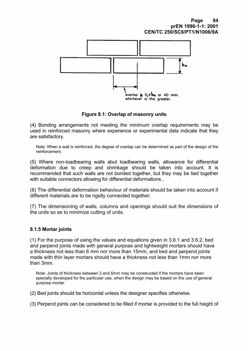
Page 94prEN 1996-1-1: 2001
CEN/TC 250/SC6/PT1/N1006/9A
Figure 8.1: Overlap of masonry units
(4) Bonding arrangements not meeting the minimum overlap requirements may beused in reinforced masonry where experience or experimental data indicate that theyare satisfactory.
Note: When a wall is reinforced, the degree of overlap can be determined as part of the design of thereinforcement.
(5) Where non-loadbearing walls abut loadbearing walls, allowance for differentialdeformation due to creep and shrinkage should be taken into account. It isrecommended that such walls are not bonded together, but they may be tied togetherwith suitable connectors allowing for differential deformations..
(6) The differential deformation behaviour of materials should be taken into account ifdifferent materials are to be rigidly connected together.
(7) The dimensioning of walls, columns and openings should suit the dimensions ofthe units so as to minimize cutting of units.
8.1.5 Mortar joints
(1) For the purpose of using the values and equations given in 3.6.1 and 3.6.2, bedand perpend joints made with general purpose and lightweight mortars should havea thickness not less than 6 mm nor more than 15mm, and bed and perpend jointsmade with thin layer mortars should have a thickness not less than 1mm nor morethan 3mm.
Note: Joints of thickness between 3 and 6mm may be constructed if the mortars have beenspecially developed for the particular use, when the design may be based on the use of generalpurpose mortar.
(2) Bed joints should be horizontal unless the designer specifies otherwise.
(3) Perpend joints can be considered to be filled if mortar is provided to the full height of
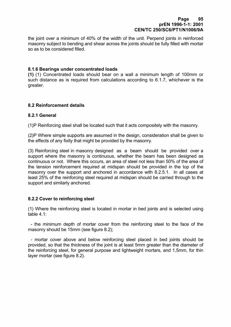
Page 95prEN 1996-1-1: 2001
CEN/TC 250/SC6/PT1/N1006/9A
the joint over a minimum of 40% of the width of the unit. Perpend joints in reinforcedmasonry subject to bending and shear across the joints should be fully filled with mortarso as to be considered filled.
8.1.6 Bearings under concentrated loads(1) (1) Concentrated loads should bear on a wall a minimum length of 100mm orsuch distance as is required from calculations according to 6.1.7, whichever is thegreater.
8.2 Reinforcement details
8.2.1 General
(1)P Reinforcing steel shall be located such that it acts compositely with the masonry.
(2)P Where simple supports are assumed in the design, consideration shall be given tothe effects of any fixity that might be provided by the masonry.
(3) Reinforcing steel in masonry designed as a beam should be provided over asupport where the masonry is continuous, whether the beam has been designed ascontinuous or not. Where this occurs, an area of steel not less than 50% of the area ofthe tension reinforcement required at midspan should be provided in the top of themasonry over the support and anchored in accordance with 8.2.5.1. In all cases atleast 25% of the reinforcing steel required at midspan should be carried through to thesupport and similarly anchored.
8.2.2 Cover to reinforcing steel
(1) Where the reinforcing steel is located in mortar in bed joints and is selected usingtable 4.1:
- the minimum depth of mortar cover from the reinforcing steel to the face of themasonry should be 15mm (see figure 8.2);
- mortar cover above and below reinforcing steel placed in bed joints should beprovided, so that the thickness of the joint is at least 5mm greater than the diameter ofthe reinforcing steel, for general purpose and lightweight mortars, and 1,5mm, for thinlayer mortar (see figure 8.2).
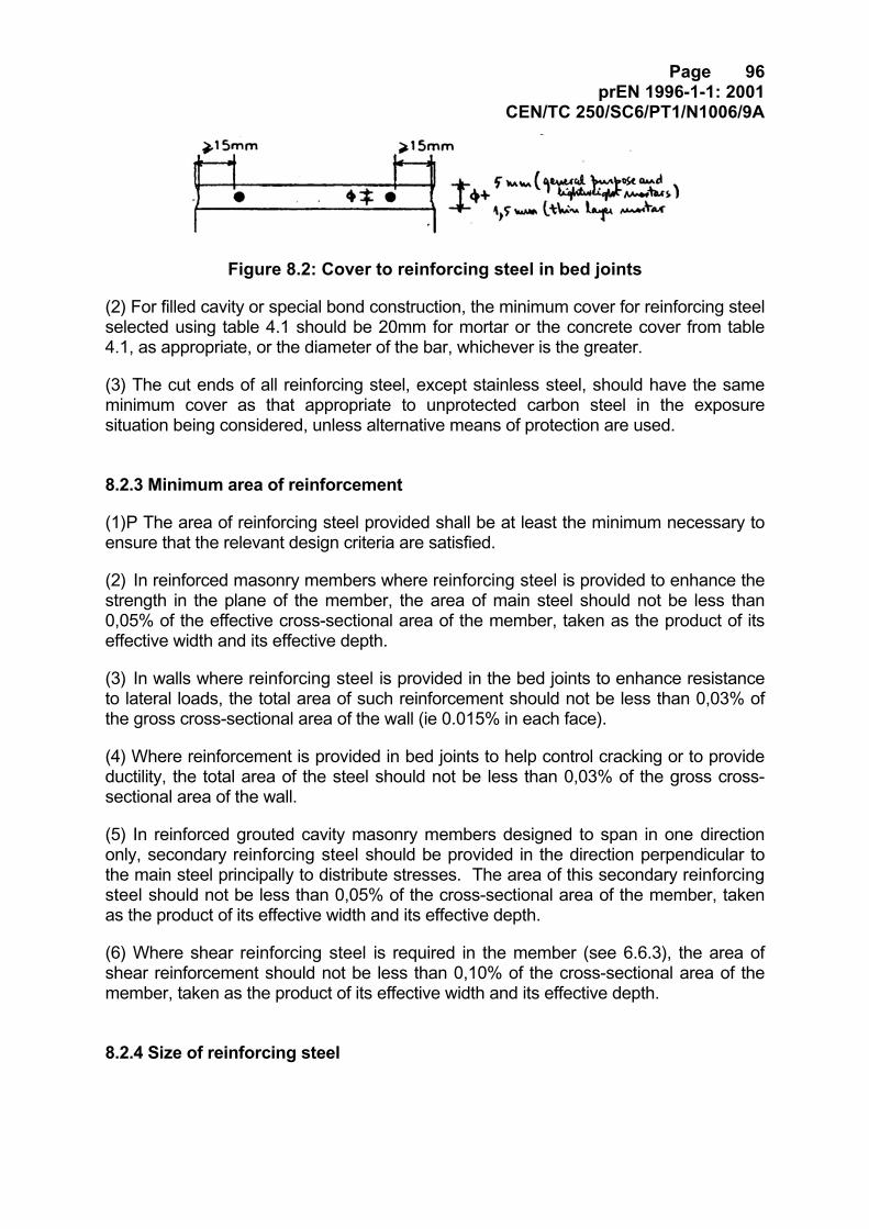
Page 96prEN 1996-1-1: 2001
CEN/TC 250/SC6/PT1/N1006/9A
Figure 8.2: Cover to reinforcing steel in bed joints
(2) For filled cavity or special bond construction, the minimum cover for reinforcing steelselected using table 4.1 should be 20mm for mortar or the concrete cover from table4.1, as appropriate, or the diameter of the bar, whichever is the greater.
(3) The cut ends of all reinforcing steel, except stainless steel, should have the sameminimum cover as that appropriate to unprotected carbon steel in the exposuresituation being considered, unless alternative means of protection are used.
8.2.3 Minimum area of reinforcement
(1)P The area of reinforcing steel provided shall be at least the minimum necessary toensure that the relevant design criteria are satisfied.
(2) In reinforced masonry members where reinforcing steel is provided to enhance thestrength in the plane of the member, the area of main steel should not be less than0,05% of the effective cross-sectional area of the member, taken as the product of itseffective width and its effective depth.
(3) In walls where reinforcing steel is provided in the bed joints to enhance resistanceto lateral loads, the total area of such reinforcement should not be less than 0,03% ofthe gross cross-sectional area of the wall (ie 0.015% in each face).
(4) Where reinforcement is provided in bed joints to help control cracking or to provideductility, the total area of the steel should not be less than 0,03% of the gross cross-sectional area of the wall.
(5) In reinforced grouted cavity masonry members designed to span in one directiononly, secondary reinforcing steel should be provided in the direction perpendicular tothe main steel principally to distribute stresses. The area of this secondary reinforcingsteel should not be less than 0,05% of the cross-sectional area of the member, takenas the product of its effective width and its effective depth.
(6) Where shear reinforcing steel is required in the member (see 6.6.3), the area ofshear reinforcement should not be less than 0,10% of the cross-sectional area of themember, taken as the product of its effective width and its effective depth.
8.2.4 Size of reinforcing steel
Page 97prEN 1996-1-1: 2001
CEN/TC 250/SC6/PT1/N1006/9A
(1)P The maximum size of reinforcing steel used shall be such as to enable properembedment in the mortar or concrete infill.
(2) Reinforcing steel should have a minimum diameter of 5 mm.
(3)P The maximum size of reinforcing steel used shall be such that the anchoragestresses, as given in 8.2.5, are not exceeded and the cover to the reinforcement, asgiven in 8.2.2, is maintained.
8.2.5 Anchorage and laps
8.2.5.1 Anchorage of tension reinforcing steel
(1)P Reinforcing steel shall be provided with sufficient anchorage length so that theinternal forces to which it is subjected are transmitted to the mortar or concrete infill andthat longitudinal cracking or spalling of the masonry is avoided.
(2) Anchorage should be achieved by straight anchorage, hooks, bends or loops asshown in figure 8.3. Alternatively stress transfer may be by means of an appropriatemechanical device proven by tests.
(3) Straight anchorage or bends (see figure 8.3 (a) and (c)) should not be used toanchor plain reinforcing steel of more than 8mm diameter. Hooks, bends or loopsshould not be used to anchor reinforcing steel in compression.
Figure 8.3: Anchorage details
Page 98prEN 1996-1-1: 2001
CEN/TC 250/SC6/PT1/N1006/9A
(4) The straight anchorage length lb required for a bar, assuming constant bond stress,should be obtained from:
(8.1)
where:
φ is the effective diameter of the reinforcing steel;
fym is the design strength of reinforcing steel, obtained from 3.4.2;
fbom is the design anchorage bond strength of reinforcing steel, obtained fromtable 3.5 or 3.6 and 3.6.4, as appropriate;
(5) For bars ended by hooks, bends and loops (see Figure 8.3 (b), (c) and (d)), theanchorage length in tension may be reduced to 0,7 lb.
(6) Where a greater area of reinforcing steel is provided than is required by design, theanchorage length may be reduced proportionally provided that:
(i) For reinforcing steel in tension the anchorage length is not less than the greater of:
- 0,3 lb , or
- 10 bar diameters, or
- 100mm.
(ii) For reinforcing steel in compression the anchorage length is not less than thegreater of:
- 0,6 lb , or
- 10 bar diameters, or
- 100mm.
(7) Where it is practicable, transverse reinforcing steel should be provided evenlydistributed along the anchorage length, with at least one reinforcing steel bar placed inthe region of a curved anchorage (see figure 8.3 (b), (c) and (d)). The total area oftransverse reinforcing steel should be not less than 25% of the area of one anchoredreinforcing steel bar.
f1 f
4 =l
mboymMb
φγ
Page 99prEN 1996-1-1: 2001
CEN/TC 250/SC6/PT1/N1006/9A
(8) Where prefabricated bed joint reinforcement is used, the anchorage lengthshould be based on the characteristic anchorage bond strength determined by testsin accordance with EN 846-2.
8.2.5.2 Lapping of tension reinforcing
(1)P The length of laps shall be sufficient to transmit the design forces.
(2) The lap length between two reinforcing steel bars should be calculated inaccordance with 8.2.5.1, based on the smaller of the two bars lapped.
(3) The lap length provided between two reinforcing steel bars should be:
- lb for bars in compression and for reinforcing steel bars in tension where less than30% of the bars in the section are lapped and where the clear distance between thelapped bars in a transverse direction is not less than 10 bar diameters and the concreteor mortar cover is not less than 5 bar diameters.
- 1,4 lb for reinforcing steel bars in tension where either 30% or more of the bars at thesection are lapped or if the clear distance between the lapped bars in a transversedirection is less than 10 bar diameters or the concrete or mortar cover is less than 5 bardiameters.
- 2 lb for reinforcing steel bars in tension where both 30% or more of the bars at thesection are lapped and the clear distance between the lapped bars is less than 10 bardiameter or the concrete or mortar cover is less than 5 bar diameters.
(4) Where it is possible, laps between reinforcing steel bars should not be located atareas of high stress or where the dimensions of a section change, for example, a stepin a wall thickness. The clear distance between two lapped bars should not be lessthan two bar diameters or 20mm whichever is the greater.
(5) Where prefabricated bed joint reinforcement is used the lap length should be basedon the characteristic anchorage bond strength determined by tests in accordance withEN 846-2.
8.2.5.3 Anchorage of shear reinforcing steel
(1) The anchorage of shear reinforcing steel, including stirrups, should be effected bymeans of hooks or bends (see figure 8.3 (b) and (c)), where appropriate, with alongitudinal reinforcing bar provided inside the hook or bend.
(2) The anchorage is considered to be satisfactory where the curve of the hook isextended by a straight length of 5 bar diameters or 50mm, whichever is the greater,and the curve of the bend is extended by a straight length of 10 bar diameters or70mm, whichever is the greater (see figure 8.4).
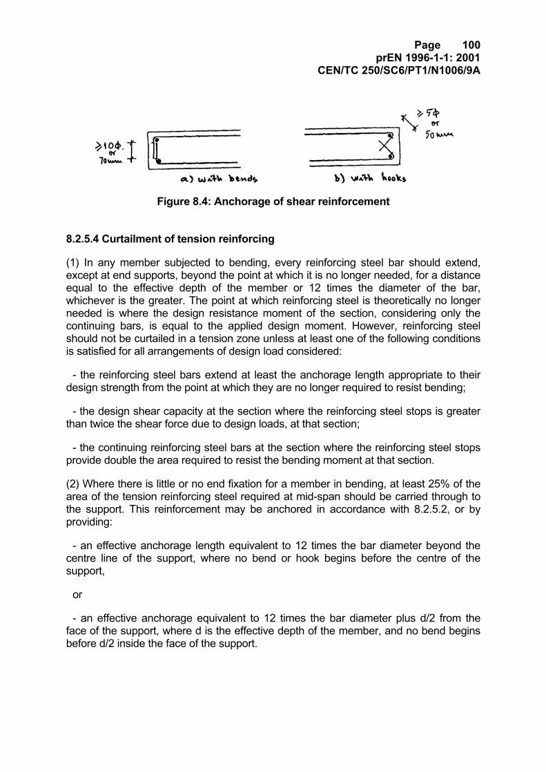
Page 100prEN 1996-1-1: 2001
CEN/TC 250/SC6/PT1/N1006/9A
Figure 8.4: Anchorage of shear reinforcement
8.2.5.4 Curtailment of tension reinforcing
(1) In any member subjected to bending, every reinforcing steel bar should extend,except at end supports, beyond the point at which it is no longer needed, for a distanceequal to the effective depth of the member or 12 times the diameter of the bar,whichever is the greater. The point at which reinforcing steel is theoretically no longerneeded is where the design resistance moment of the section, considering only thecontinuing bars, is equal to the applied design moment. However, reinforcing steelshould not be curtailed in a tension zone unless at least one of the following conditionsis satisfied for all arrangements of design load considered:
- the reinforcing steel bars extend at least the anchorage length appropriate to theirdesign strength from the point at which they are no longer required to resist bending;
- the design shear capacity at the section where the reinforcing steel stops is greaterthan twice the shear force due to design loads, at that section;
- the continuing reinforcing steel bars at the section where the reinforcing steel stopsprovide double the area required to resist the bending moment at that section.
(2) Where there is little or no end fixation for a member in bending, at least 25% of thearea of the tension reinforcing steel required at mid-span should be carried through tothe support. This reinforcement may be anchored in accordance with 8.2.5.2, or byproviding:
- an effective anchorage length equivalent to 12 times the bar diameter beyond thecentre line of the support, where no bend or hook begins before the centre of thesupport,
or
- an effective anchorage equivalent to 12 times the bar diameter plus d/2 from theface of the support, where d is the effective depth of the member, and no bend beginsbefore d/2 inside the face of the support.
Page 101prEN 1996-1-1: 2001
CEN/TC 250/SC6/PT1/N1006/9A
(3) Where the distance from the face of a support to the nearer edges of a principalload is less than twice the effective depth, all the main reinforcing steel in a membersubjected to bending should continue to the support and be provided with ananchorage equivalent to 20 times the bar diameter.
8.2.6 Restraint of compression reinforcing steel
(1)P Reinforcing steel bars in compression shall be restrained to prevent local buckling.
(2) In members where the area of longitudinal reinforcing steel is greater than 0,25% ofthe area of the masonry and any concrete infill, and more than 25% of the design axialload resistance is to be used, links surrounding the longitudinal bars should beprovided.
(3) Where links are required, they should be not less than 4mm in diameter or 1/4 ofthe maximum diameter of the longitudinal bars, whichever is the greater, and thespacing should not exceed the least of:
- the least lateral dimension of the wall;
- 300mm;
- 12 times the main bar diameters.
(4) Vertical reinforcing steel corner bars should be supported by an internal angle atevery link spacing and this angle should not exceed 135°. Internal vertical reinforcingbars need only be restrained by internal angles at alternate link spacings.
8.2.7 Spacing of reinforcing steel
(1)P The spacing of reinforcing steel shall be sufficiently large so as to allow theconcrete infill or mortar to be placed and compacted.
(2) The clear distance between adjacent parallel reinforcing steel should not be lessthan the maximum size of the aggregate plus 5mm, or the bar diameter, or 10mmwhichever is the greater.
(3) Except when reinforcing steel is concentrated in cores or pockets, the spacing oftension reinforcement should not exceed 400mm.
(4) When the main reinforcing steel is concentrated in cores or pockets, for example,in pocket type walls, the spacing centre to centre of the concentrations of mainreinforcing steel should be at a maximum of 600mm. The total area of main reinforcingsteel should not exceed 4% of the gross cross-sectional area of the infill in the core orpocket, except at laps where it should not exceed 8%.
Page 102prEN 1996-1-1: 2001
CEN/TC 250/SC6/PT1/N1006/9A
(5) Where shear reinforcing steel is required, the spacing of stirrups should not begreater than 0,75 x effective depth of the member or 300 mm, whichever is lesser.
(6) Prefabricated bed joint reinforcement placed in bed joints should be spaced at600mm, or less, centres.
8.3 Prestressing details
(1) Detailing of prestressing devices should be in accordance with pr EN 1992-1-1.
8.4 Confined masonry details
(1) P Confined masonry walls shall be provided with vertical and horizontal reinforcedconcrete or reinforced masonry confining elements so that they act together as a singlestructural member when subjected to actions.
(2)P Top and sides confining elements shall be cast after the masonry has been builtso that they will be duly anchored together.
(3) Confining elements should be provided at every floor level, at every interceptionbetween walls and at both sides of every opening having an area of more that 1,5 m2.Additional confining elements may be required in the walls so that the maximumspacing, both horizontal and vertical is 4 m (figure 8.5).
(4) Confining elements should have a cross-sectional area not less than 0,02 m2,with a minimum dimension of 150 mm in the plan of the wall, and be provided withlongitudinal reinforcements with a minimum area equivalent to 0,8 % of the cross-sectional area of the confining element, but not less than 200 mm2. Stirrups not lessthan 6 mm diameter, spaced not more than 300 mm should also be provided. Thedetailing of the reinforcements should be in accordance with 8.2.
(5) In confined masonry walls where Group 1 and Group 2 Units are used, the unitsadjacent to the confining elements should be overlapped according to the rulesprescribed in the clause 8.1.3 for bonding of masonry. Alternatively, reinforcementnot less than 6 mm diameter bars or equivalent and spaced not more than 400 mm,duly anchored in the concrete infill and in the mortar joints, should be adopted.
8.5 Connection of walls
8.5.1 Connection of walls to floors and roofs
8.5.1.1 General
Page 103prEN 1996-1-1: 2001
CEN/TC 250/SC6/PT1/N1006/9A
(1)P Where walls are assumed to be restrained by floors or roofs, the walls shall beconnected to the floors or roofs so as to provide for the transfer of the design lateralloads to the bracing elements.
(2) Transfer of lateral loads to the bracing elements should be made by the floor or roofstructure, for example, reinforced or precast concrete or timber joists incorporatingboarding, provided the floor or roof structure is capable of developing diaphragmaction, or by a ring beam capable of transferring the resulting shear and bending actioneffects. Either the frictional resistance of the bearing of structural members on masonrywalls, or metal straps of suitable and fixing, should be capable of resisting the transferloads.
(3)P Where a floor or roof bears on a wall, the bearing length shall be sufficient toprovide the required bearing capacity and shear resistance, allowing for manufacturingand erection tolerances.
(4) The minimum bearing length of floors or roofs on walls should be as for bearingsunder concentrated loads (see 8.1.6).
8.5.1.2 Connection by straps
(1)P Where straps are used they shall be capable of transferring the lateral loadsbetween the wall and the restraining structural element.
(2) When the surcharge on the wall is negligible, for example, at a gable wall/roofjunction, special consideration is necessary to ensure that the connection between thestraps and the wall will be effective.
(3) The spacing of straps between walls and floors or roofs should be not greater than2 m for buildings up to 4 storeys high, and 1,25 m for higher buildings.
8.5.1.3 Connection by frictional resistance
(1)P Where concrete floors, roofs or ring beams bear directly on a wall, the frictionalresistance shall be capable of transferring the lateral loads.
(2) Straps are not necessary if the bearing of a concrete floor or roof extends to thecentre of the wall or 100mm, whichever is the greater, providing no sliding bearing isformed.
8.5.1.4 Ring ties and ring beams
(1) When the transfer of lateral loads to the bracing elements is to be achieved bythe use of ring beams:
Page 104prEN 1996-1-1: 2001
CEN/TC 250/SC6/PT1/N1006/9A
- the ring ties are placed in every floor level or directly below. They may consist ofreinforced concrete, reinforced masonry, steel or wood and should be able tosupport a design tensile force of 30kN.
- when ring ties are not continuous, additional measures should be undertaken toensure continuity.
- ring ties made of reinforced concrete should be reinforced by at least tworeinforcing steel bars of at least 150mm2. The laps should be designed inaccordance with ENV 1992-1-1 and staggered, if possible. Ring ties made ofreinforced concrete or reinforced masonry should be reinforced. Parallel continuousreinforcement may be considered with their full cross section provided that they aresituated in floors or window lintels at a distance of not more than 0,5m from themiddle of the wall and floor, respectively.
(2) If floors without diaphragm action are used or sliding layers are put under thefloor bearings due to deformations of the roof floor, the horizontal stiffening of thewalls should be ensured by ring beams or statically equivalent measures.
8.5.2 Connection between walls
8.5.2.1 General
(1)P Intersecting loadbearing walls shall be joined together so that the required verticaland lateral loads can be transferred between them.
(2) The joint at the intersection of walls should be made either by:
- masonry bond (see 8.1.4), or
- connectors or reinforcement extending into each wall.
(3) Intersecting loadbearing walls should be erected simultaneously.
8.5.2.2 Cavity walls
(1)P The two leaves of a cavity wall shall be effectively tied together.
(2) The number of wall ties connecting together the two leaves of a cavity wall shouldbe not less than 2 ties/m² of the cavity wall, nor less than the number calculatedaccording to 6.3.3, where relevant.
Note: When connecting elements, for example, prefabricated bed joint reinforcement, are used toconnect two leaves of a wall together, each tying element should be treated as a wall tie.
(3)P The wall ties shall be corrosion resistant for the relevant exposure class for thewall (see section 4).
Page 105prEN 1996-1-1: 2001
CEN/TC 250/SC6/PT1/N1006/9A
(4)P Additional wall ties shall be provided at a free edge to connect both leavestogether.
(5) Where an opening penetrates a wall and the frame for the opening is not capable oftransferring the horizontal design action directly to the structure, those wall ties whichwould have been placed in the opening should be redistributed uniformly along thevertical edges of the opening.
(6) Due allowance should be made for any differential movement between the leaves,or between a leaf and a frame, in the selection of the wall ties.
8.5.2.3 Double-leaf walls.
(1)P The two leaves of a double-leaf wall shall be effectively tied together.
(2) Ties connecting the two leaves, calculated according to 6.3.3, should have aminimum cross-sectional area of 300 mm²/m² of the double-leaf wall, for steelconnectors, and with the connectors evenly distributed, being not less than 2connectors/m2 of the double-leaf wall.
Note: Some forms of prefabricated bed joint reinforcement can also function as ties between the twoleaves of a double-leaf wall (see EN 845-3).
(3)P The connectors shall be corrosion resistant for the relevant exposure class for thewall (see 4.3.6)
(4) Due allowance should be made for any differential movement between the leaves inthe selection of the connector.
8.6 Chases and recesses on walls
8.6.1 General
(1)P Chases and recesses shall not impair the stability of the wall.
(2) Chases and recesses should not be allowed if the depth of the chase or recesswould be greater than half the thickness of the shell of the unit, unless the strength ofthe wall is verified by calculation.
(3) Chases and recesses should not pass through lintels or other structural items builtinto a wall nor should they be allowed in reinforced masonry members unlessspecifically allowed for by the designer.
(4) In cavity walls, the provision of chases and recesses should be consideredseparately for each leaf.
Page 106prEN 1996-1-1: 2001
CEN/TC 250/SC6/PT1/N1006/9A
8.6.2 Vertical chases and recesses
(1) The reduction in vertical load, shear and flexural resistance resulting from verticalchases and recesses may be neglected if such vertical chases and recesses are keptwithin the limits given in table 8.1, with the depth of the recess or chase taken toinclude the depth of any hole reached when forming the recess or chase. If these limitsare exceeded, the vertical load, shear and flexural resistance should be checked bycalculation.
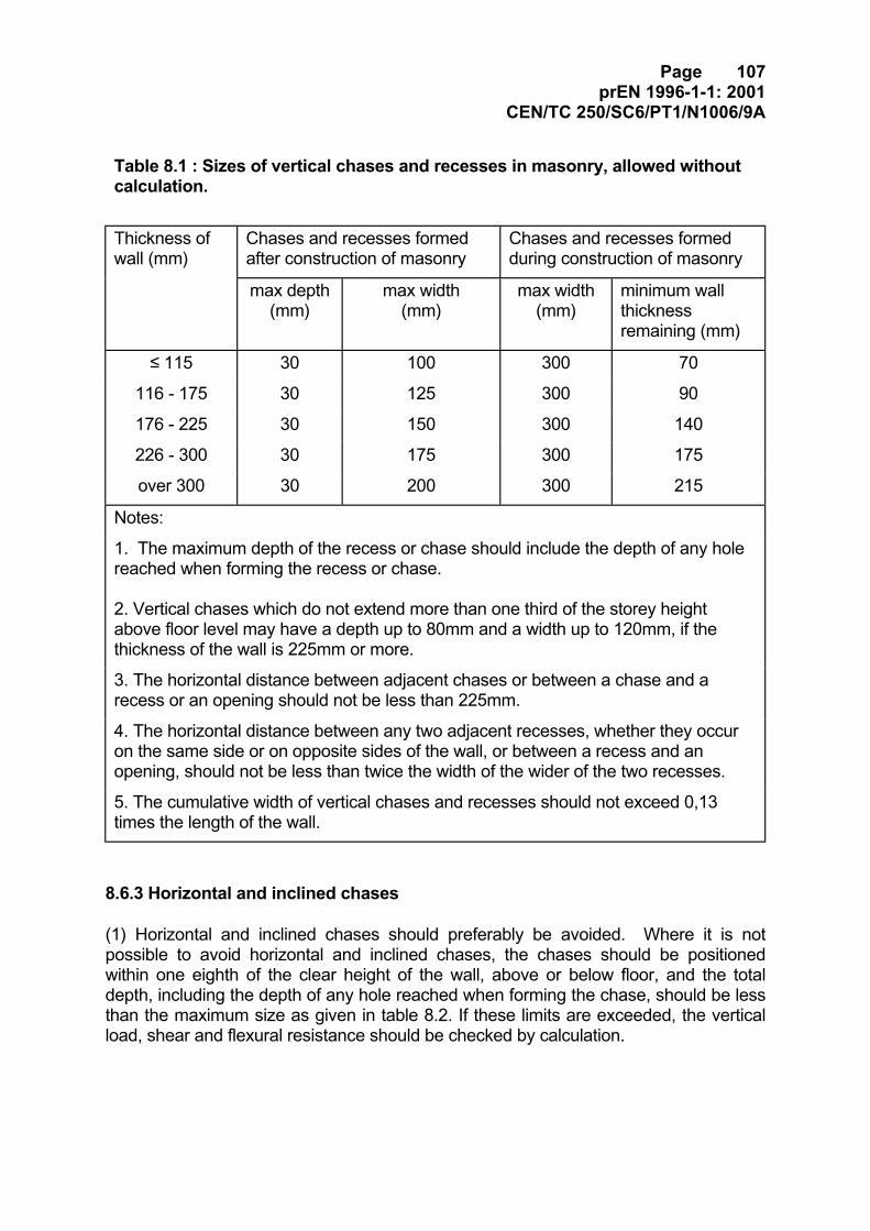
Page 107prEN 1996-1-1: 2001
CEN/TC 250/SC6/PT1/N1006/9A
Table 8.1 : Sizes of vertical chases and recesses in masonry, allowed withoutcalculation.
Thickness ofwall (mm)
Chases and recesses formedafter construction of masonry
Chases and recesses formedduring construction of masonry
max depth(mm)
max width(mm)
max width(mm)
minimum wallthicknessremaining (mm)
≤ 115 30 100 300 70
116 - 175 30 125 300 90
176 - 225 30 150 300 140
226 - 300 30 175 300 175
over 300 30 200 300 215
Notes:
1. The maximum depth of the recess or chase should include the depth of any holereached when forming the recess or chase.
2. Vertical chases which do not extend more than one third of the storey heightabove floor level may have a depth up to 80mm and a width up to 120mm, if thethickness of the wall is 225mm or more.
3. The horizontal distance between adjacent chases or between a chase and arecess or an opening should not be less than 225mm.
4. The horizontal distance between any two adjacent recesses, whether they occuron the same side or on opposite sides of the wall, or between a recess and anopening, should not be less than twice the width of the wider of the two recesses.
5. The cumulative width of vertical chases and recesses should not exceed 0,13times the length of the wall.
8.6.3 Horizontal and inclined chases
(1) Horizontal and inclined chases should preferably be avoided. Where it is notpossible to avoid horizontal and inclined chases, the chases should be positionedwithin one eighth of the clear height of the wall, above or below floor, and the totaldepth, including the depth of any hole reached when forming the chase, should be lessthan the maximum size as given in table 8.2. If these limits are exceeded, the verticalload, shear and flexural resistance should be checked by calculation.
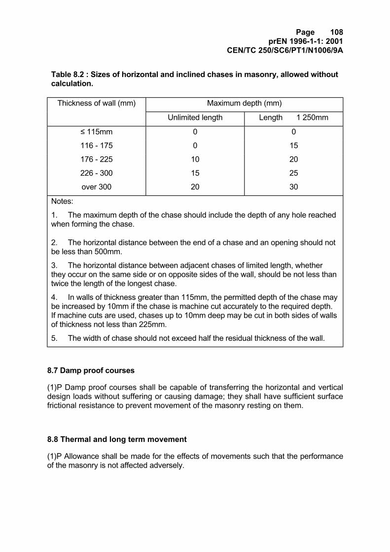
Page 108prEN 1996-1-1: 2001
CEN/TC 250/SC6/PT1/N1006/9A
Table 8.2 : Sizes of horizontal and inclined chases in masonry, allowed withoutcalculation.
Thickness of wall (mm) Maximum depth (mm)
Unlimited length Length�� 1 250mm
≤ 115mm 0 0
116 - 175 0 15
176 - 225 10 20
226 - 300 15 25
over 300 20 30
Notes:
1. The maximum depth of the chase should include the depth of any hole reachedwhen forming the chase.
2. The horizontal distance between the end of a chase and an opening should notbe less than 500mm.
3. The horizontal distance between adjacent chases of limited length, whetherthey occur on the same side or on opposite sides of the wall, should be not less thantwice the length of the longest chase.
4. In walls of thickness greater than 115mm, the permitted depth of the chase maybe increased by 10mm if the chase is machine cut accurately to the required depth.If machine cuts are used, chases up to 10mm deep may be cut in both sides of wallsof thickness not less than 225mm.
5. The width of chase should not exceed half the residual thickness of the wall.
8.7 Damp proof courses
(1)P Damp proof courses shall be capable of transferring the horizontal and verticaldesign loads without suffering or causing damage; they shall have sufficient surfacefrictional resistance to prevent movement of the masonry resting on them.
8.8 Thermal and long term movement
(1)P Allowance shall be made for the effects of movements such that the performanceof the masonry is not affected adversely.
Page 109prEN 1996-1-1: 2001
CEN/TC 250/SC6/PT1/N1006/9A
(2) Vertical and horizontal movement joints should be provided to allow for the effectsof thermal and moisture movement, creep and deflection and the possible effects ofinternal stresses caused by vertical or lateral loading, so that the masonry does notsuffer damage.
(3) In determining the maximum spacing of vertical movement joints, specialconsideration should be given to the effects of the following:
- the drying shrinkage of calcium silicate units, aggregate concrete units, autoclavedaerated concrete units and manufactured stone units;
- the irreversible moisture expansion of the units;
- variations in temperature and humidity;
- insulation provided to the masonry;
- the provision of prefabricated bed joint reinforcement.
(4) In the case of ties with fixed supports are used, precautions should be taken toallow for vertical movement of external walls. The uninterrupted height betweenhorizontal movement joints in the outer leaf of external cavity walls should be limited toavoid the loosening of the wall ties. Pinned supported ties or ties which are free tomove in the vertical direction should in general be used.
(5) The width of vertical and horizontal movement joints should allow for the maximummovement expected. If expansion joints are to be filled then they should be filled withan easily compressed material.
Page 110prEN 1996-1-1: 2001
CEN/TC 250/SC6/PT1/N1006/9A
9. Execution
9.1 General
(1)P All work shall be constructed in accordance with the specified details withinpermissible deviations.
(2)P All work shall be executed by appropriately skilled and experienced personnel.
(3) If the requirements of EN 1996-2 are followed, it can be assumed that (1)P and (2)Pare satisfied.
9.2 Design of structural members
(1) It should be determined whether special precautions are necessary to ensure theoverall stability of the structure or of individual walls during construction.
9.3 Loading of masonry
(1)P Masonry shall not be subjected to load until it has achieved adequate strength toresist the load without damage.
(2) Backfilling against retaining walls should not be carried out until the wall is capableof resisting loads from the filling operation, taking account of any compacting forces orvibrations.
(3) Attention should be paid to walls which are temporarily unrestrained during con-struction, but which may be subjected to wind loads or construction loads, andtemporary shoring should be provided, if necessary, to maintain stability.
Page 111prEN 1996-1-1: 2001
CEN/TC 250/SC6/PT1/N1006/9A
ANNEXES
Annex A (informative): Consideration of partial safety factors relating toExecution
(1) If a country wishes to link a class, or classes, of γM from 2.3 to execution control, thefollowing should be considered in differentiating the class, or classes, of γM:
- the availability of appropriately qualified and experienced personnel, employed bythe contractor, for supervision of the work;
- the availability of appropriately qualified and experienced personnel, independent ofthe contractor’s staff, for the inspection of the work;
Note: In the case of Design -and-Build contracts, the Designer may be considered as a personindependent of the construction organisation for the purposes of inspection of the work, provided thatthe Designer is an appropriately qualified person who reports to senior management independently ofthe site construction team.
- assessment of the site properties of the mortar and concrete infill;
- the way in which mortars are mixed and the constituents are batched, for example,either by weight or in appropriate measuring boxes.
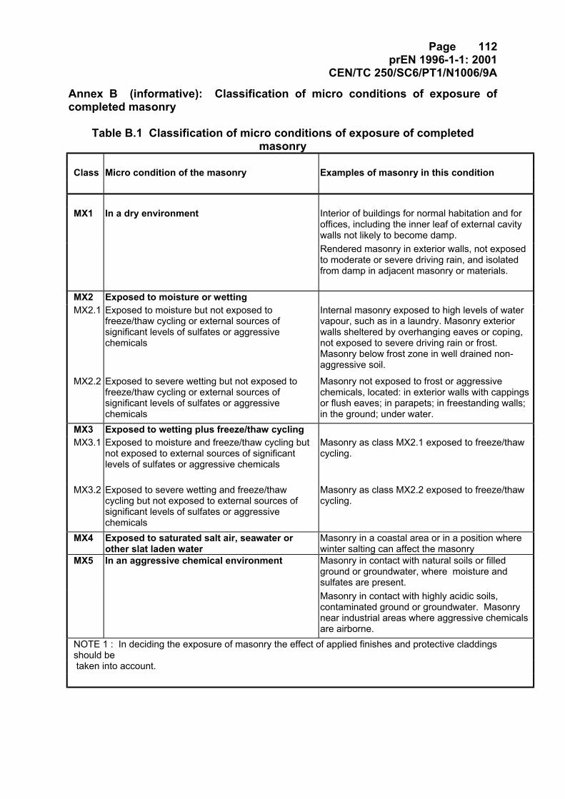
Page 112prEN 1996-1-1: 2001
CEN/TC 250/SC6/PT1/N1006/9A
Annex B (informative): Classification of micro conditions of exposure ofcompleted masonry
Table B.1 Classification of micro conditions of exposure of completedmasonry
Class Micro condition of the masonry Examples of masonry in this condition
MX1 In a dry environment Interior of buildings for normal habitation and foroffices, including the inner leaf of external cavitywalls not likely to become damp.Rendered masonry in exterior walls, not exposedto moderate or severe driving rain, and isolatedfrom damp in adjacent masonry or materials.
MX2 Exposed to moisture or wettingMX2.1 Exposed to moisture but not exposed to
freeze/thaw cycling or external sources ofsignificant levels of sulfates or aggressivechemicals
Internal masonry exposed to high levels of watervapour, such as in a laundry. Masonry exteriorwalls sheltered by overhanging eaves or coping,not exposed to severe driving rain or frost.Masonry below frost zone in well drained non-aggressive soil.
MX2.2 Exposed to severe wetting but not exposed tofreeze/thaw cycling or external sources ofsignificant levels of sulfates or aggressivechemicals
Masonry not exposed to frost or aggressivechemicals, located: in exterior walls with cappingsor flush eaves; in parapets; in freestanding walls;in the ground; under water.
MX3 Exposed to wetting plus freeze/thaw cyclingMX3.1 Exposed to moisture and freeze/thaw cycling but
not exposed to external sources of significantlevels of sulfates or aggressive chemicals
Masonry as class MX2.1 exposed to freeze/thawcycling.
MX3.2 Exposed to severe wetting and freeze/thawcycling but not exposed to external sources ofsignificant levels of sulfates or aggressivechemicals
Masonry as class MX2.2 exposed to freeze/thawcycling.
MX4 Exposed to saturated salt air, seawater orother slat laden water
Masonry in a coastal area or in a position wherewinter salting can affect the masonry
MX5 In an aggressive chemical environment Masonry in contact with natural soils or filledground or groundwater, where moisture andsulfates are present.Masonry in contact with highly acidic soils,contaminated ground or groundwater. Masonrynear industrial areas where aggressive chemicalsare airborne.
NOTE 1 : In deciding the exposure of masonry the effect of applied finishes and protective claddingsshould be taken into account.
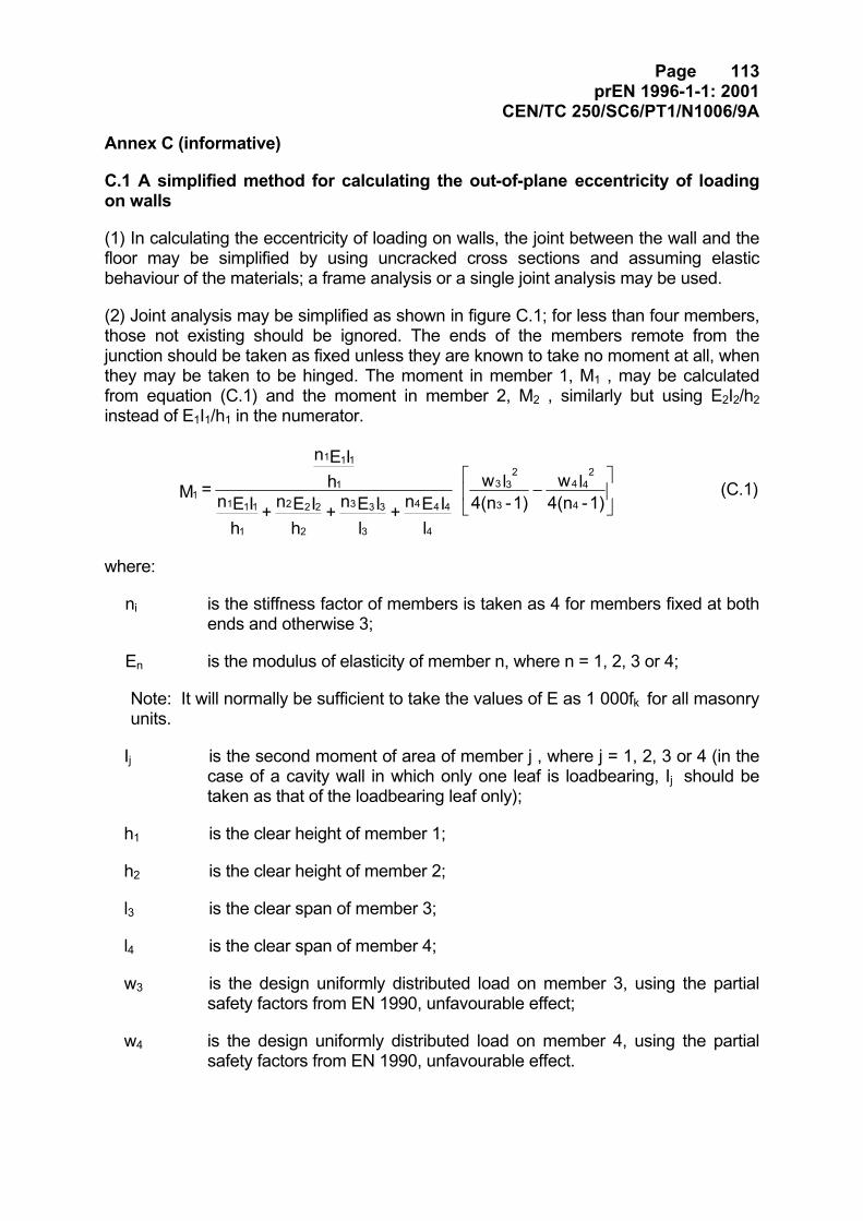
Page 113prEN 1996-1-1: 2001
CEN/TC 250/SC6/PT1/N1006/9A
Annex C (informative)
C.1 A simplified method for calculating the out-of-plane eccentricity of loadingon walls
(1) In calculating the eccentricity of loading on walls, the joint between the wall and thefloor may be simplified by using uncracked cross sections and assuming elasticbehaviour of the materials; a frame analysis or a single joint analysis may be used.
(2) Joint analysis may be simplified as shown in figure C.1; for less than four members,those not existing should be ignored. The ends of the members remote from thejunction should be taken as fixed unless they are known to take no moment at all, whenthey may be taken to be hinged. The moment in member 1, M1 , may be calculatedfrom equation (C.1) and the moment in member 2, M2 , similarly but using E2I2/h2instead of E1I1/h1 in the numerator.
−
1)-4(nlw
1)-4(nlw
lIEn +
lIEn +
hIEn +
hIEn
hIEn
= M4
42
4
3
32
3
4
444
3
333
2
222
1
111
1
111
1 (C.1)
where:
ni is the stiffness factor of members is taken as 4 for members fixed at bothends and otherwise 3;
En is the modulus of elasticity of member n, where n = 1, 2, 3 or 4;
Note: It will normally be sufficient to take the values of E as 1 000fk for all masonryunits.
Ij is the second moment of area of member j , where j = 1, 2, 3 or 4 (in thecase of a cavity wall in which only one leaf is loadbearing, Ij should betaken as that of the loadbearing leaf only);
h1 is the clear height of member 1;
h2 is the clear height of member 2;
l3 is the clear span of member 3;
l4 is the clear span of member 4;
w3 is the design uniformly distributed load on member 3, using the partialsafety factors from EN 1990, unfavourable effect;
w4 is the design uniformly distributed load on member 4, using the partialsafety factors from EN 1990, unfavourable effect.
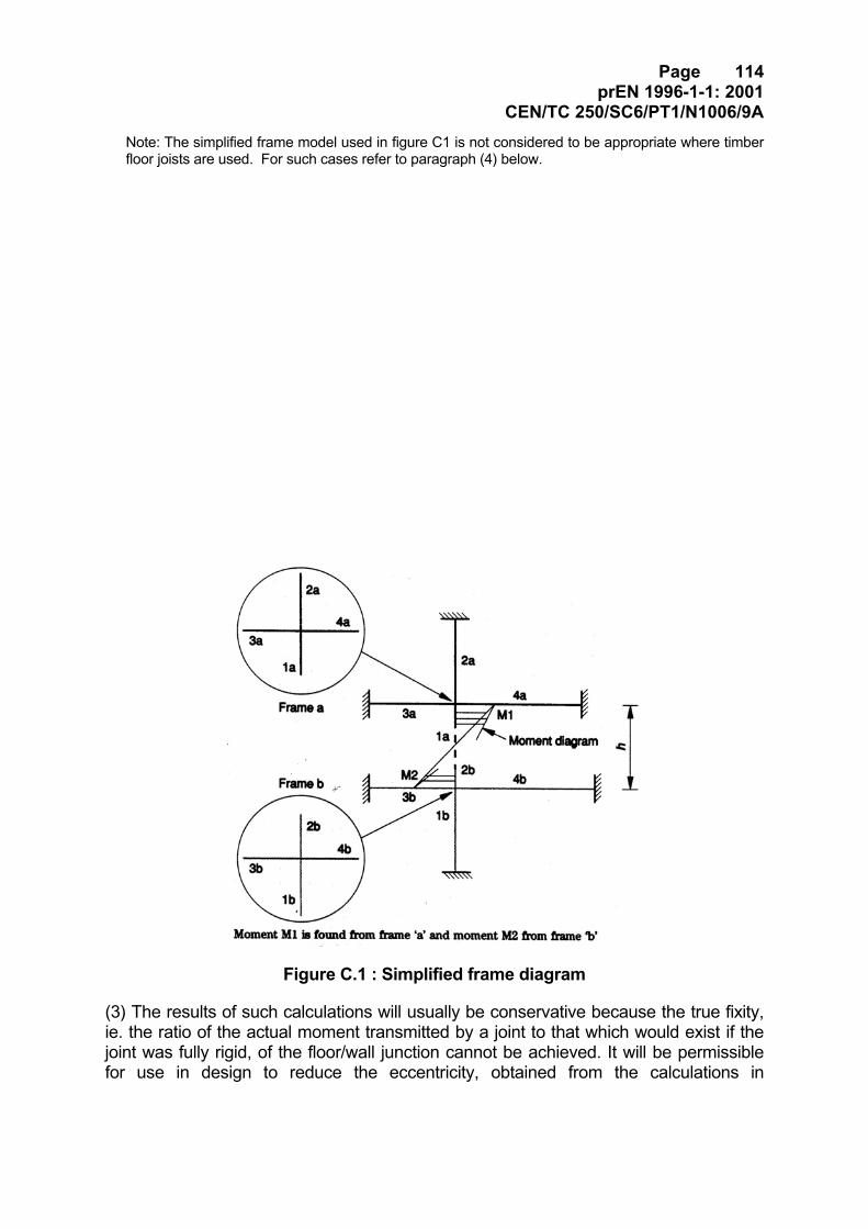
Page 114prEN 1996-1-1: 2001
CEN/TC 250/SC6/PT1/N1006/9ANote: The simplified frame model used in figure C1 is not considered to be appropriate where timberfloor joists are used. For such cases refer to paragraph (4) below.
Figure C.1 : Simplified frame diagram
(3) The results of such calculations will usually be conservative because the true fixity,ie. the ratio of the actual moment transmitted by a joint to that which would exist if thejoint was fully rigid, of the floor/wall junction cannot be achieved. It will be permissiblefor use in design to reduce the eccentricity, obtained from the calculations in
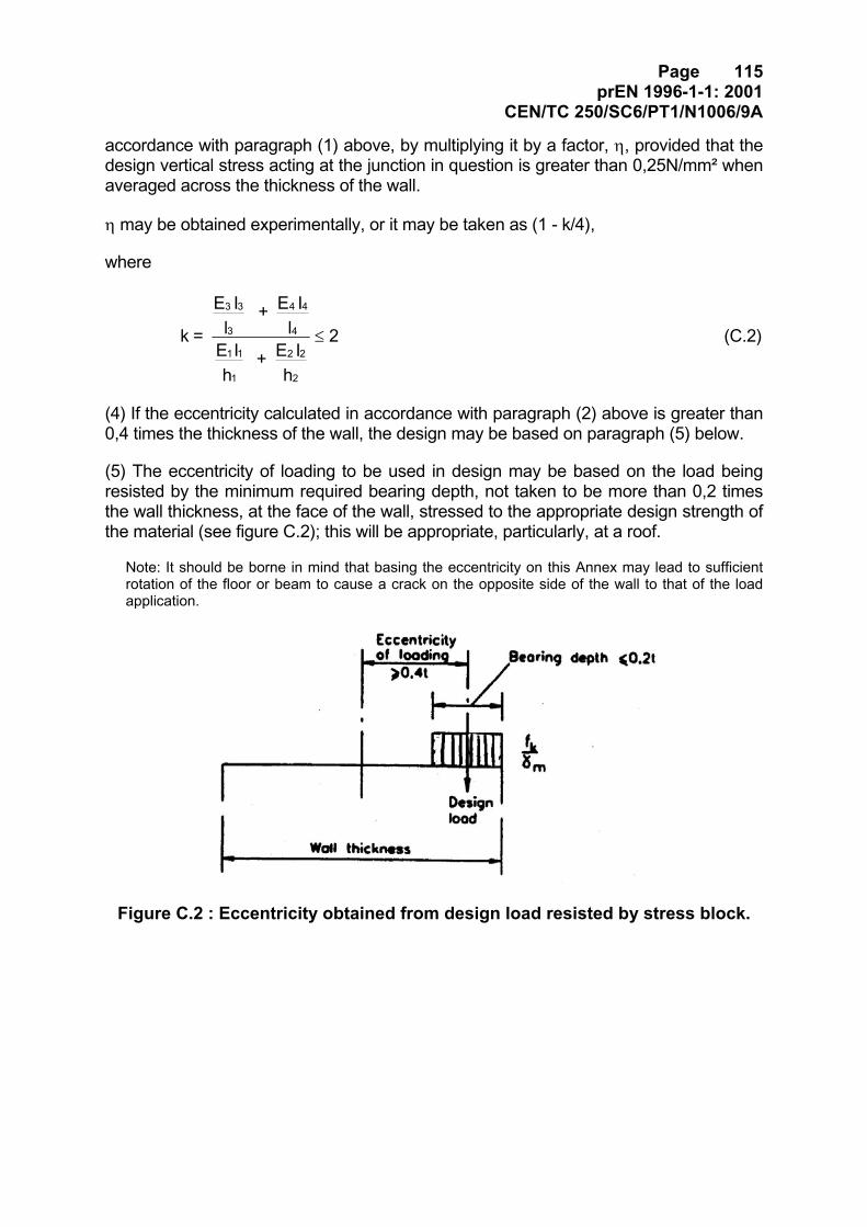
Page 115prEN 1996-1-1: 2001
CEN/TC 250/SC6/PT1/N1006/9A
accordance with paragraph (1) above, by multiplying it by a factor, η, provided that thedesign vertical stress acting at the junction in question is greater than 0,25N/mm² whenaveraged across the thickness of the wall.
η may be obtained experimentally, or it may be taken as (1 - k/4),
where
2
hI E +
hI E
lI E +
lI E
= k
2
22
1
11
4
44
3
33
≤ (C.2)
(4) If the eccentricity calculated in accordance with paragraph (2) above is greater than0,4 times the thickness of the wall, the design may be based on paragraph (5) below.
(5) The eccentricity of loading to be used in design may be based on the load beingresisted by the minimum required bearing depth, not taken to be more than 0,2 timesthe wall thickness, at the face of the wall, stressed to the appropriate design strength ofthe material (see figure C.2); this will be appropriate, particularly, at a roof.
Note: It should be borne in mind that basing the eccentricity on this Annex may lead to sufficientrotation of the floor or beam to cause a crack on the opposite side of the wall to that of the loadapplication.
Figure C.2 : Eccentricity obtained from design load resisted by stress block.

Page 116prEN 1996-1-1: 2001
CEN/TC 250/SC6/PT1/N1006/9A
Annex D
Temporarily removed to Part -1-3
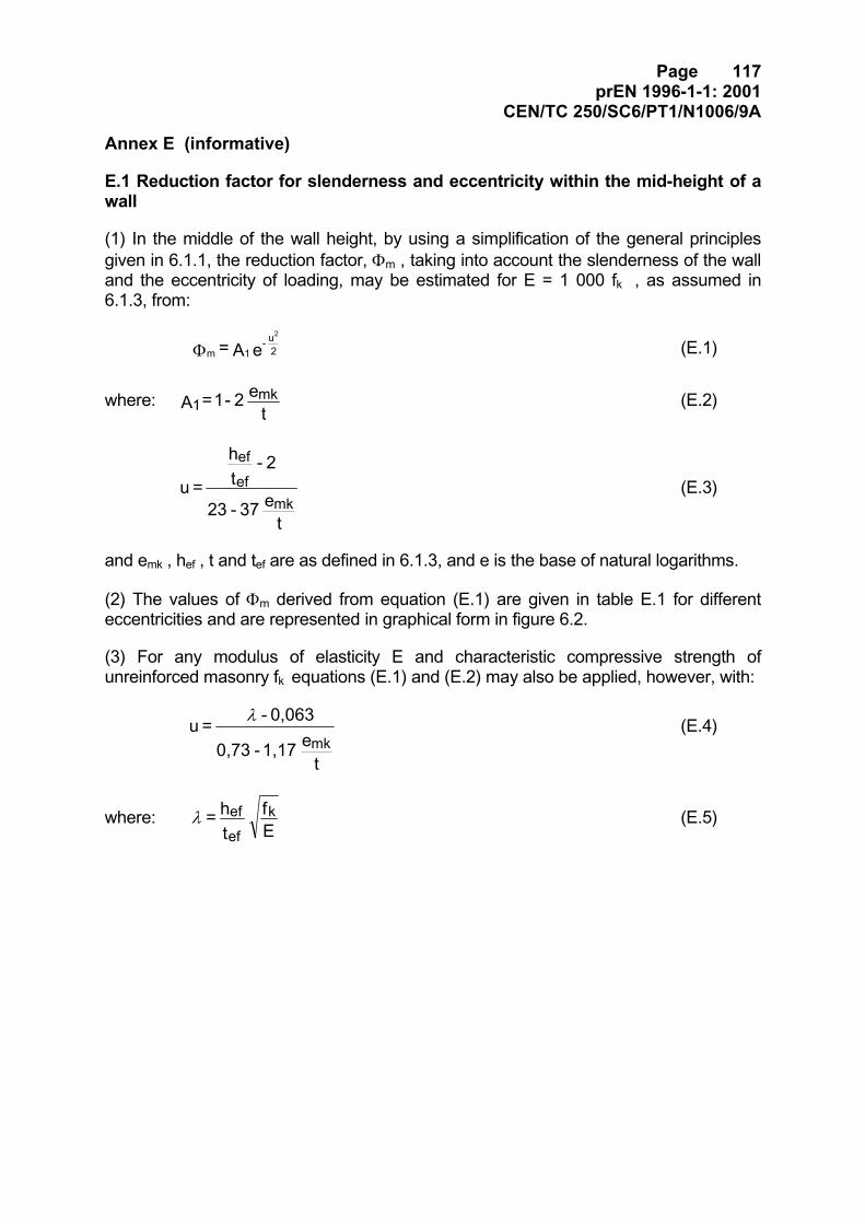
Page 117prEN 1996-1-1: 2001
CEN/TC 250/SC6/PT1/N1006/9A
Annex E (informative)
E.1 Reduction factor for slenderness and eccentricity within the mid-height of awall
(1) In the middle of the wall height, by using a simplification of the general principlesgiven in 6.1.1, the reduction factor, Φm , taking into account the slenderness of the walland the eccentricity of loading, may be estimated for E = 1 000 fk , as assumed in6.1.3, from:
e A = 2u -
1m
2
Φ (E.1)
where:t
e 2 - 1 = A mk1 (E.2)
te 37 - 23
2 - th
= umk
ef
ef
(E.3)
and emk , hef , t and tef are as defined in 6.1.3, and e is the base of natural logarithms.
(2) The values of Φm derived from equation (E.1) are given in table E.1 for differenteccentricities and are represented in graphical form in figure 6.2.
(3) For any modulus of elasticity E and characteristic compressive strength ofunreinforced masonry fk equations (E.1) and (E.2) may also be applied, however, with:
te 1,17 - 0,73
0,063 - = umk
λ (E.4)
where:Ef
th = k
ef
efλ (E.5)

Page 118prEN 1996-1-1: 2001
CEN/TC 250/SC6/PT1/N1006/9ATable E.1 : Capacity reduction factor, Φm , for E = 1 000 fk
Slendernessratiohef /tef
Eccentricity e mk
0,05 t 0,10 t 0,15 t 0,20t 0,25t 0,30t 0,33t0 0,90 0,80 0,70 0,60 0,50 0,40 0,3412345
0,900,900,900,900,89
0,800,800,800,800,79
0,700,700,700,700,69
0,600,600,600,600,59
0,500,500,500,490,49
0,400,400,400,390,39
0,340,340,340,330,33
678910
0,880,880,860,850,84
0,780,770,760,750,73
0,680,670,660,650,63
0,580,570,560,540,53
0,480,470,450,440,42
0,380,370,350,340,32
0,320,310,290,280,26
1112131415
0,820,800,790,770,75
0,720,700,680,660,64
0,610,590,570,550,53
0,510,490,470,450,42
0,400,380,360,340,32
0,300,280,260,240,22
0,240,220,200,180,16
1617181920
0,720,700,680,650,63
0,610,590,570,540,52
0,510,480,460,440,41
0,400,380,350,330,31
0,300,280,250,230,21
0,200,180,160,140,13
0,150,130,110,100,08
2122232425
0,600,580,550,520,50
0,490,470,440,420,39
0,390,360,340,320,29
0,290,260,240,220,20
0,190,17o,160,140,12
0,110,100,080,070,06
0,070,060,050,040,04
2627282930
0,470,450,420,400,37
0,370,350,320,300,28
0,270,250,230,210,19
0,180,170,150,130,12
0,110,100,080,070,06
0,050,040,040,030,03
0,030,020,020,010,01
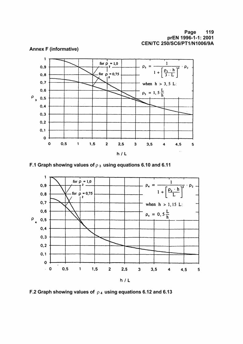
Page 119prEN 1996-1-1: 2001
CEN/TC 250/SC6/PT1/N1006/9AAnnex F (informative)
F.1 Graph showing values of ρ 3 using equations 6.10 and 6.11
F.2 Graph showing values of ρ 4 using equations 6.12 and 6.13
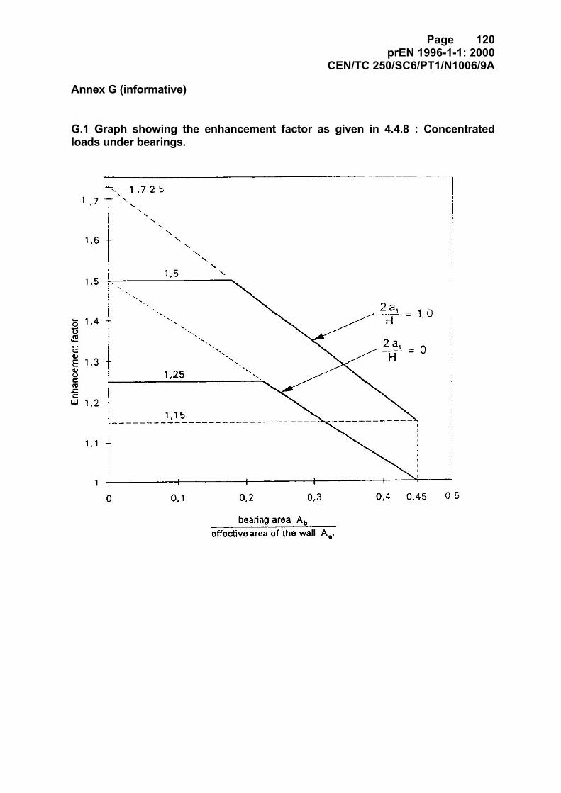
Page 120prEN 1996-1-1: 2000
CEN/TC 250/SC6/PT1/N1006/9A
Annex G (informative)
G.1 Graph showing the enhancement factor as given in 4.4.8 : Concentratedloads under bearings.
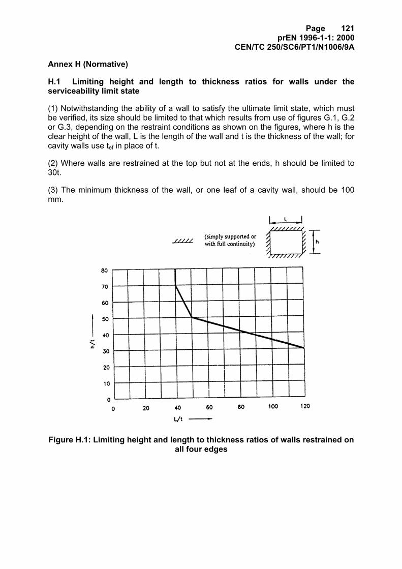
Page 121prEN 1996-1-1: 2000
CEN/TC 250/SC6/PT1/N1006/9A
Annex H (Normative)
H.1 Limiting height and length to thickness ratios for walls under theserviceability limit state
(1) Notwithstanding the ability of a wall to satisfy the ultimate limit state, which mustbe verified, its size should be limited to that which results from use of figures G.1, G.2or G.3, depending on the restraint conditions as shown on the figures, where h is theclear height of the wall, L is the length of the wall and t is the thickness of the wall; forcavity walls use tef in place of t.
(2) Where walls are restrained at the top but not at the ends, h should be limited to30t.
(3) The minimum thickness of the wall, or one leaf of a cavity wall, should be 100mm.
Figure H.1: Limiting height and length to thickness ratios of walls restrained onall four edges
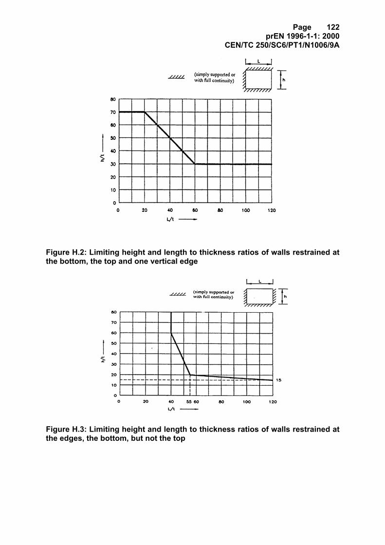
Page 122prEN 1996-1-1: 2000
CEN/TC 250/SC6/PT1/N1006/9A
Figure H.2: Limiting height and length to thickness ratios of walls restrained atthe bottom, the top and one vertical edge
Figure H.3: Limiting height and length to thickness ratios of walls restrained atthe edges, the bottom, but not the top
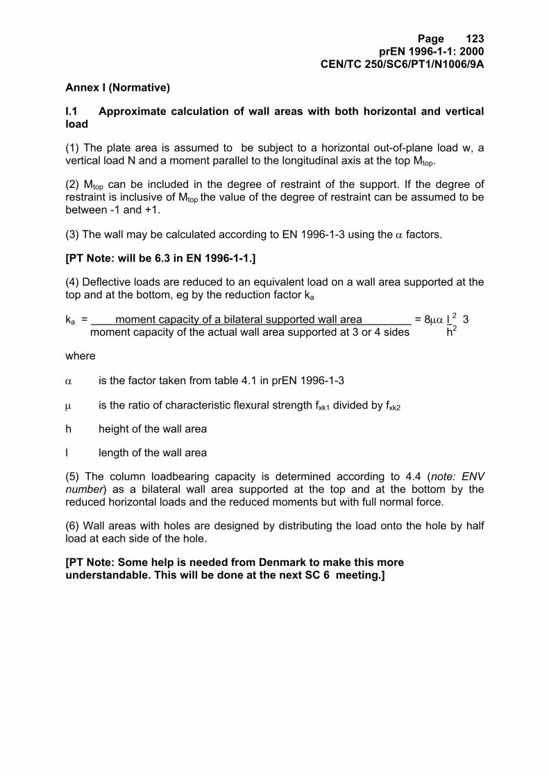
Page 123prEN 1996-1-1: 2000
CEN/TC 250/SC6/PT1/N1006/9A
Annex I (Normative)
I.1 Approximate calculation of wall areas with both horizontal and verticalload
(1) The plate area is assumed to be subject to a horizontal out-of-plane load w, avertical load N and a moment parallel to the longitudinal axis at the top Mtop.
(2) Mtop can be included in the degree of restraint of the support. If the degree ofrestraint is inclusive of Mtop the value of the degree of restraint can be assumed to bebetween -1 and +1.
(3) The wall may be calculated according to EN 1996-1-3 using the α factors.
[PT Note: will be 6.3 in EN 1996-1-1.]
(4) Deflective loads are reduced to an equivalent load on a wall area supported at thetop and at the bottom, eg by the reduction factor ka
ka = moment capacity of a bilateral supported wall area = 8µα l 2 3 moment capacity of the actual wall area supported at 3 or 4 sides h2
where
α is the factor taken from table 4.1 in prEN 1996-1-3
µ is the ratio of characteristic flexural strength fxk1 divided by fxk2
h height of the wall area
l length of the wall area
(5) The column loadbearing capacity is determined according to 4.4 (note: ENVnumber) as a bilateral wall area supported at the top and at the bottom by thereduced horizontal loads and the reduced moments but with full normal force.
(6) Wall areas with holes are designed by distributing the load onto the hole by halfload at each side of the hole.
[PT Note: Some help is needed from Denmark to make this moreunderstandable. This will be done at the next SC 6 meeting.]