Embed Size (px)
Citation preview
Preliminary Valve Location Engineering Assessment
Ref. # 777081011
Rev. D
Date: August 2011
Attachment JRP IR 3.3 a)
Preliminary Valve Location Engineering Assessment
Ref. No.: 777081011 Rev. D August 2011 Draft i
Document History
Rev. Date Summary of Changes Document Originator
A May 21, 2009 Initial Draft J. W. Wilson
B Mar 8, 20011 General Updates J. W. Wilson
C August 2011 Peer Review J. W. Wilson
D August 2011 JRP Submission J. W. Wilson
Approval
Rev. Date Implementation Approval Signature
D August 2011
Document Owner
Raymond Doering
Business Unit
Engineering
Business Unit
[Name]
Attachment JRP IR 3.3 a)
Preliminary Valve Location Engineering Assessment
Ref. No.: 777081011 Rev. D August 2011 Draft ii
Summary
This report outlines the preliminary engineering assessment work completed to date, including initial assumptions for valve design and placement, volume out calculations and the location selection criteria used to select the preliminary locations for the mainline block valves.
The report provides a preliminary list of valve locations for both the oil and condensate pipelines based on Pipeline Route Rev. T and provides the volume out calculations and pipeline plots showing the pipeline profile and volume outs at selected watercourses.
Attachment JRP IR 3.3 a)
Preliminary Valve Location Engineering Assessment
Ref. No.: 777081011 Rev. D August 2011 Draft iii
Table of Contents
SUMMARY .......................................................................................................................... II
1.0 PROJECT DESCRIPTION ........................................................................................... 4
2.0 INTRODUCTION ....................................................................................................... 4
3.0 VALVE DESIGN AND LOCATION ASSUMPTIONS .......................................................... 5
4.0 PIPELINE VOLUME OUT DETERMINATION .................................................................. 5
5.0 VALVE LOCATION SELECTION CRITERIA ................................................................... 6
6.0 SITE SPECIFIC VALVE PLACEMENT CONSIDERATIONS .................................................. 7
7.0 RESULTS ................................................................................................................ 8
8.0 FUTURE WORK ....................................................................................................... 8
Appendix 1 List of Abbreviations .............................................................................................9 Appendix 2 Watercourse Crossing Methods for Review Sites ...............................................10 Appendix 3 Preliminary Valve Locations ...............................................................................15 Appendix 4 Volume Out Plots and Results ............................................................................18
Attachment JRP IR 3.3 a)
Preliminary Valve Location Engineering Assessment
Ref. No.: 777081011 Rev. D August 2011 Draft 4
1.0 PROJECT DESCRIPTION
The Project will consist of:
● An oil pipeline, 914 mm OD (NPS 36), approximately 1177 km long having an average annual throughput of 83,400 m3 (525,000 bbl per day), with an initiating oil pump station to be located near Bruderheim, Alberta, six intermediate oil pump stations locations (all common with the condensate pump stations) and a tank and marine terminal to be located near Kitimat, British Columbia, on the west side of Kitimat Arm;
● A condensate pipeline, 508 mm OD (NPS 20), approximately 1177 km long, located in the same right of way as the oil pipeline, having an average annual throughput of 30,700 m3 (193,000 bbl per day), with an initiating condensate pump station at the tank and marine terminal to be located near Kitimat, British Columbia, eight intermediate pump stations (six of which are common with the oil pump stations) and a terminus at Bruderheim, Alberta;
● Two tunnels that will route the oil and condensate pipelines through the mountains between the Clore River and Hoult Creek valleys and will be approximately 6.5 km and 6.6 km long, respectively.
2.0 INTRODUCTION
Valves1 are installed on a pipeline to allow the line to be shut down in a controlled manner, either for regular operational and maintenance requirements or for response to a potential operating emergency. In the unlikely event of a failure of, or damage to, the pipeline, the valves enable operations to isolate an outage and minimize release volumes.
This engineering assessment report details:
● Valve design and initial placement assumptions
● Pipeline volume out determination 1 Northern Gateway’s valves at locations other than pump stations will be remotely controlled mainline block valves (“RCMLVs”). For the purposes of this report these RCMLVs will be referred to simply as ‘valves’.
Attachment JRP IR 3.3 a)
Preliminary Valve Location Engineering Assessment
Ref. No.: 777081011 Rev. D August 2011 Draft 5
● Initial selection criteria for valve locations near watercourse crossings
● The factors influencing site specific placement at a particular location
● Results
● Future work
3.0 VALVE DESIGN AND LOCATION ASSUMPTIONS
The following are the initial assumptions used for valve design and placement. These assumptions will be reviewed as engineering activities progress.
● All block valves will be fully automated and remotely operated from the Enbridge Control Centre.
● Remotely controlled mainline block valves are set to be completely closed within 5 minutes of detection of an alarm event.
● All mainline block valves at the same site will be closed simultaneously.
● Where valves on both the oil and the condensate pipelines are required to address risk at the same location both valves will be located at a common site.
● Block valves will be located at all pump stations, the Kitimat Terminal and the Bruderheim Station.
● Maximum pipeline design flow rate (583,000 bbl per day) was used in the calculations of output during the shutdown procedure. In addition to the continuing flow through the pipelines, the volume out calculations also assumed that the pipeline would experience a 100% outage. This is a worst case scenario and conservative estimate because it assumes a full bore rupture and complete release or product.
4.0 PIPELINE VOLUME OUT DETERMINATION
Northern Gateway has developed a proprietary volume out computer model to provide an estimate of potential maximum volume released at any location
Attachment JRP IR 3.3 a)
Preliminary Valve Location Engineering Assessment
Ref. No.: 777081011 Rev. D August 2011 Draft 6
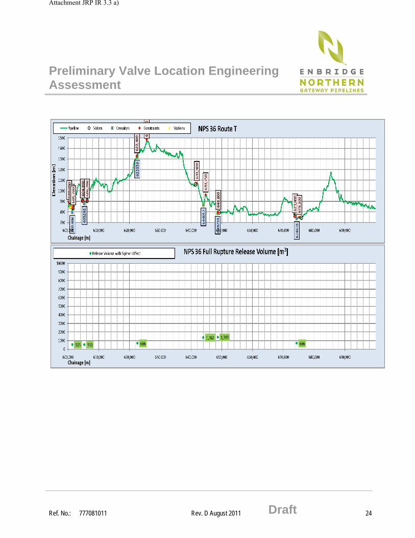
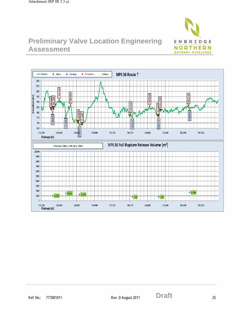
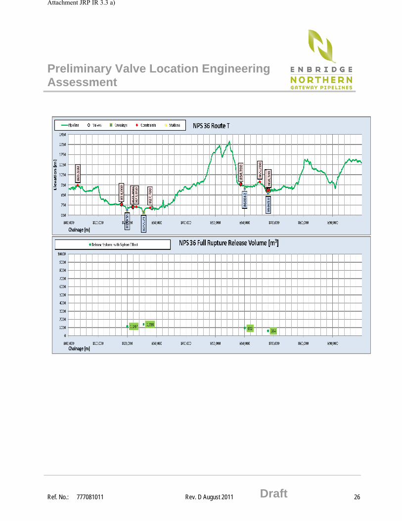
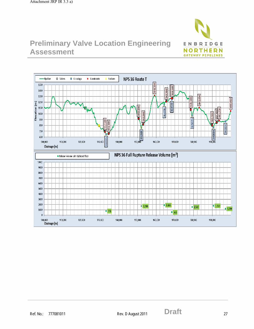
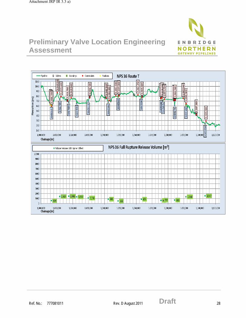
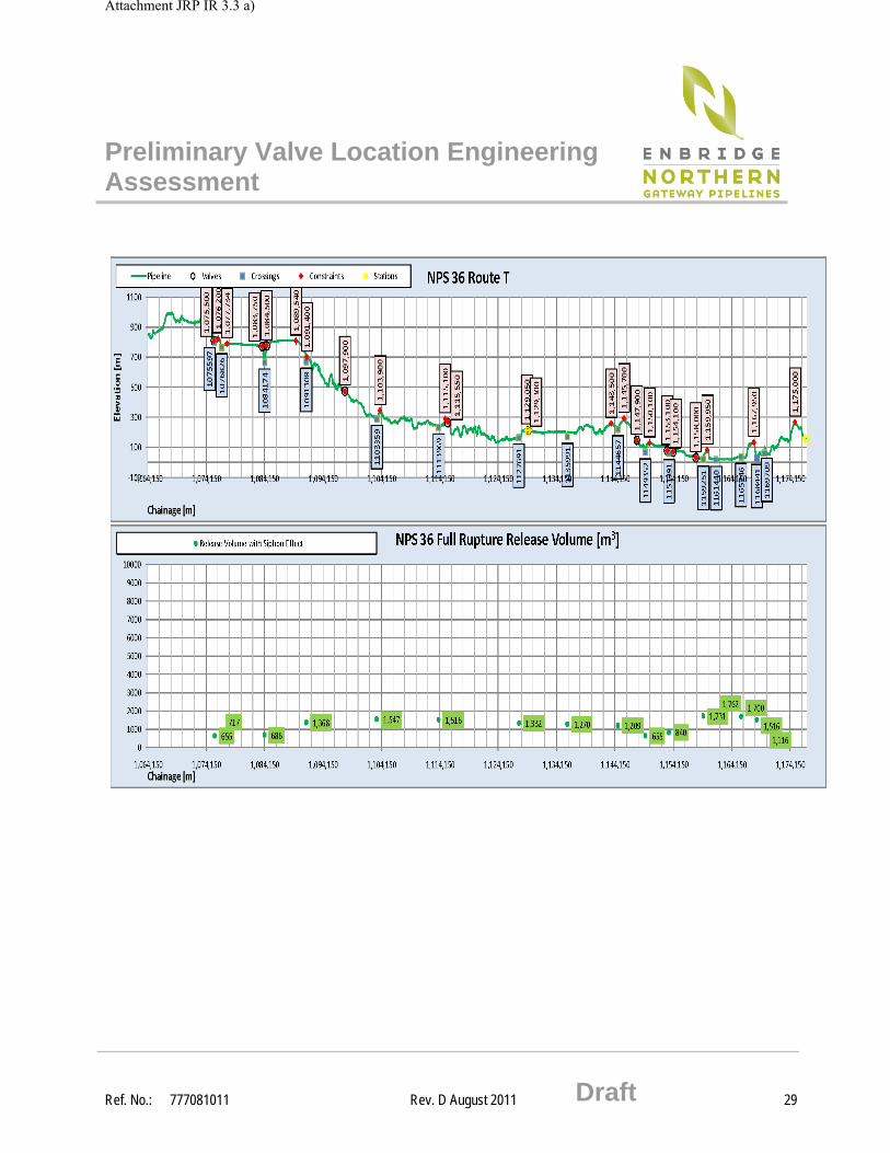
along the pipeline. The potential volume out is based on dynamic (pressurized) release prior to full valve closure plus the static volume after valve closure. The model uses assumptions of flow rates and valve closure times detailed in the previous section. For the static volume the topographic profile is examined to determine the amount of release due to gravity drainage of product taking into account all natural profile constraints. In addition, the model takes into account the ‘siphon effect’ caused by the complete blockage of the pipeline at the valve location restraining a “head” of product behind each natural constraint equivalent to the atmospheric pressure at the location of the breach.
5.0 VALVE LOCATION SELECTION CRITERIA
Valves are a regulatory requirement as outlined in the Canadian Standards Association CSA Z662-07, Section 4.4.3 which states:
“Isolating valves shall be installed for the purposes of isolating the pipeline for maintenance and for response to operating emergencies…”
and also in Section 4.4.8 which states:
”For HVP and LVP pipelines, valves shall be installed on both sides of major water crossings and at other locations appropriate for the terrain in order to limit damage from accidental discharge.”
Based on these requirements the general strategy for valve locations for the preliminary engineering assessment was selected as:
● Valves to be placed within each of the pump stations, at the Kitimat Terminal and at the Bruderheim Station.
● Valves to be placed at all major water crossings, which for the Project is defined as a watercourse having a channel width >= 30 m.
● Valves will also be considered near additional water crossing locations using, as a guideline, the list of watercourse crossings for individual review (see Appendix 2) to limit the potential spill volumes.
The location of block valves along the pipelines are considered to reduce the potential consequence of a pipeline failure. Pipeline crossings of
Attachment JRP IR 3.3 a)
Preliminary Valve Location Engineering Assessment
Ref. No.: 777081011 Rev. D August 2011 Draft 7
watercourses were specifically considered, as they often represent highly sensitive environments and are generally considered to be more difficult to clean-up in the event of a spill.
As a starting point, the list of pipeline watercourse crossing individual review sites (Appendix 2) was used as a guideline to determine possible locations for mainline valves. These 83 watercourse crossings were chosen for detailed crossing method review based on whether any of the following criteria were met:
● high fish and fish habitat sensitivity
● flow rate > 1.5 m3/s expected at the time of construction
● channel width >=10 m
● significant engineering or constructability issues
A further consideration for identification of valve locations was the requirement to limit the potential spill volume at these watercourses to less than 2,000 cubic metres. As discussed previously, a volume out calculator was developed to enable the project to determine, at any location along the pipeline, what the potential maximum spill volume would be based on product flow rate, spill detection and valve closure times, pipeline profile and natural topographic constraints. In some cases the local topographic profile at a watercourse may naturally limit the spill volume to less than 2,000 cubic metres, in which case no valve was identified for that location.
6.0 SITE SPECIFIC VALVE PLACEMENT CONSIDERATIONS
Following the selection of a general location for a mainline block valve, the site specific location for the valve site is determined based on a number of factors including:
● A secure installation that is not subject to geohazards such as slides, avalanches, avulsion or lateral erosion of streams, rock fall or flooding.
● Ability to provide access, preferably on the ground and preferably year round.
● Proximity to local power supply.
Attachment JRP IR 3.3 a)
Preliminary Valve Location Engineering Assessment
Ref. No.: 777081011 Rev. D August 2011 Draft 8
● Level or gently sloping ground with sufficient room to service the valves.
● Other nearby land-use considerations including avoidance where possible of locations where placement of a valve could be a hindrance to other land uses or users.
● Avoidance of locations where third party strikes could increase risk.
7.0 RESULTS
Based on the criteria described in Sections 5.0 and 6.0, the preliminary list of block valve locations for the oil and condensate pipelines were developed, as shown in Appendix 3.
Volume out plots and results for the oil pipeline, based on the preliminary list of block valve locations, are provided in Appendix 4 These results are based on data consistent with Route Rev T, filed with the Update to Volume 3 in December 2010.
8.0 FUTURE WORK
The list of preliminary block valve locations and full-bore rupture release volumes will be reviewed and updated as engineering activities progress. The review will take into account revised assumptions for valve design and operations, pipeline route changes and additional engineering and environmental information. The valve location selection criteria will also be updated as the pipeline risk assessment, described below, progresses.
The valve location engineering assessment will also be integrated into the pipeline risk assessment. The risk assessment includes hazard identification, frequency analysis and consequence analysis. The resulting risk estimation, combining the frequency and consequence analyses, is used in the broader context of risk evaluation where the significance of risk is assessed and mitigation options, including valve locations, are identified and implemented, where appropriate, to lower the risk.
Attachment JRP IR 3.3 a)
Preliminary Valve Location Engineering Assessment
Ref. No.: 777081011 Rev. D August 2011 Draft 9
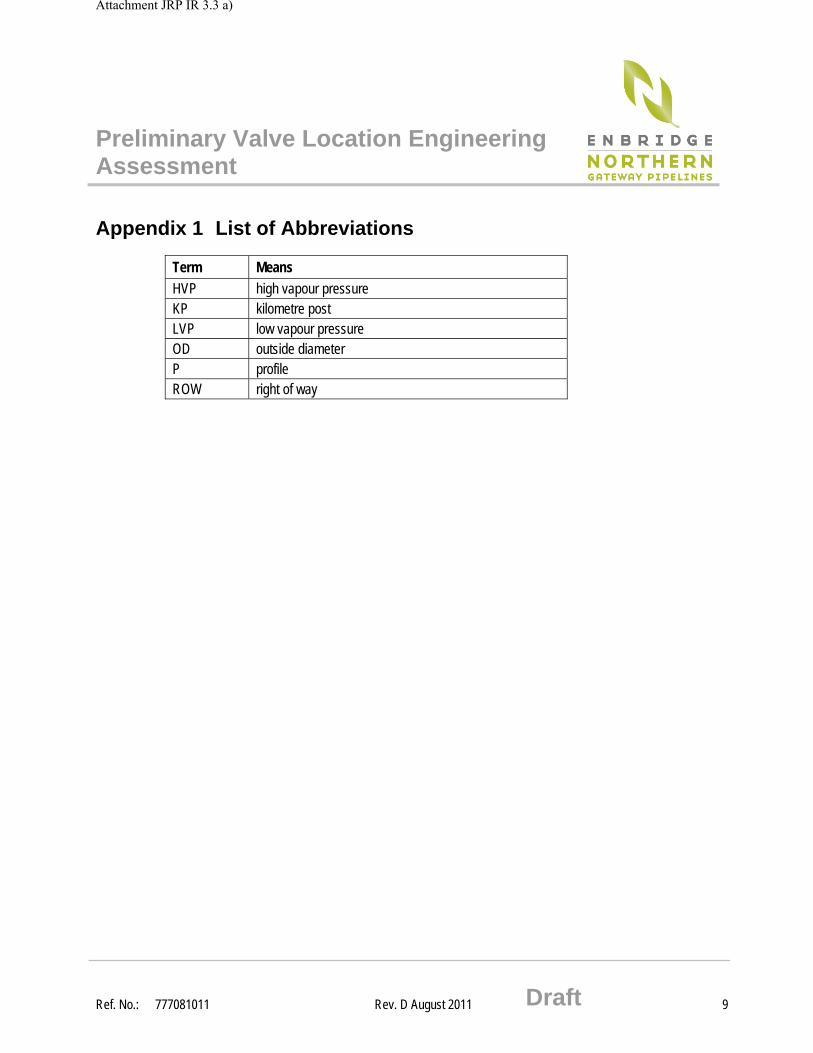
Appendix 1 List of Abbreviations
Term Means
HVP high vapour pressure KP kilometre post LVP low vapour pressure OD outside diameter P profile ROW right of way
Attachment JRP IR 3.3 a)
Preliminary Valve Location Engineering Assessment
Ref. No.: 777081011 Rev. D August 2011 Draft 10
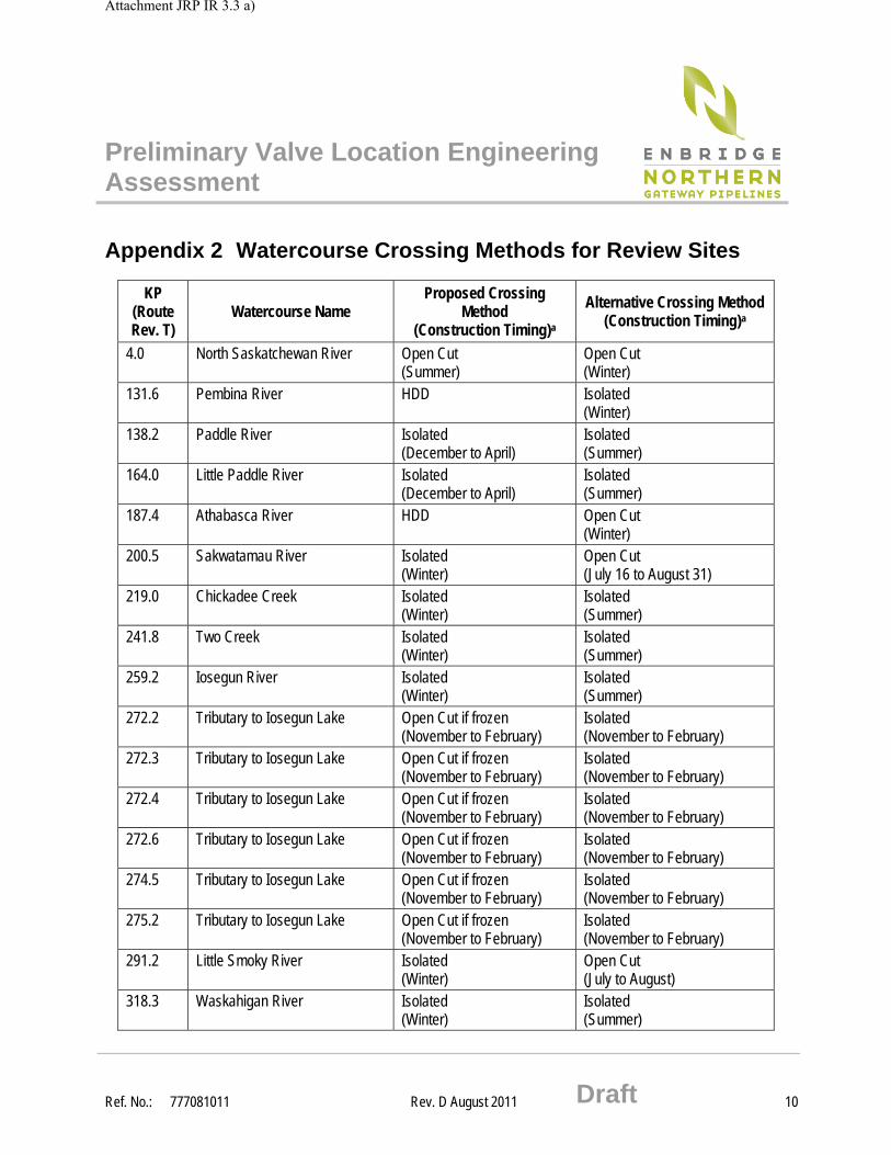
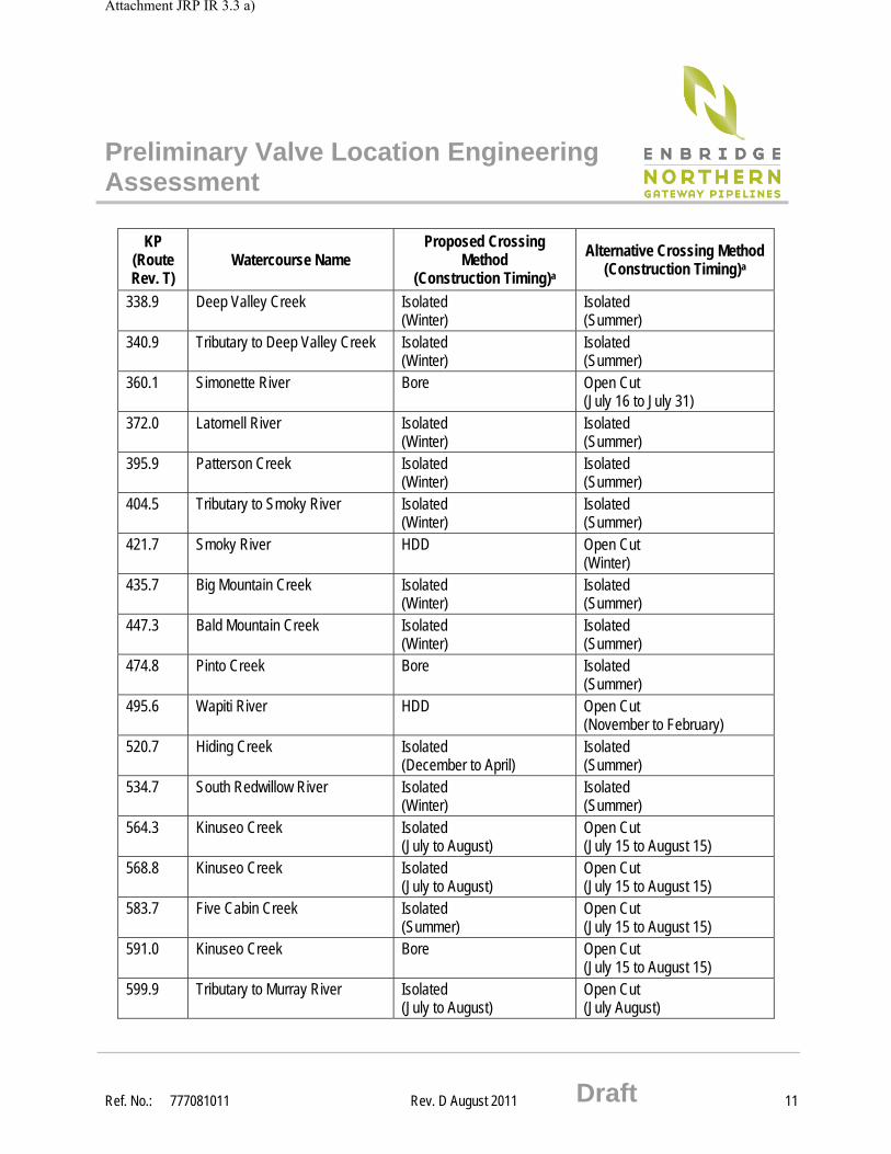
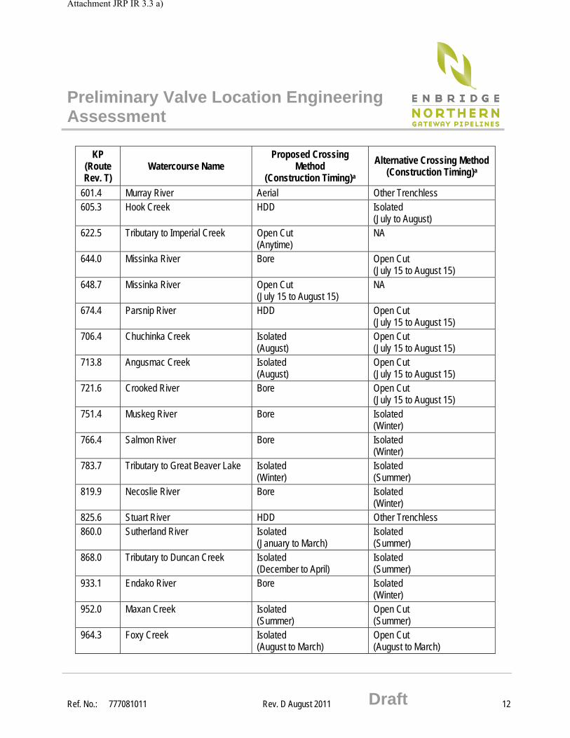
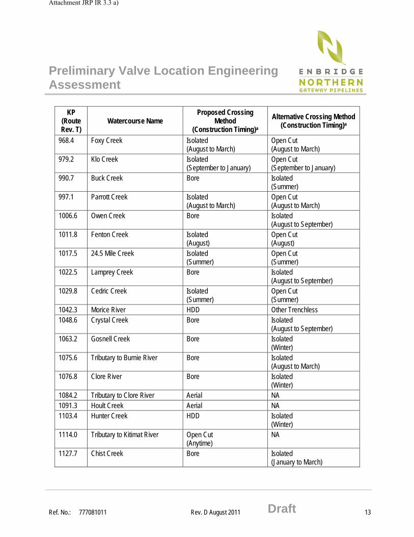
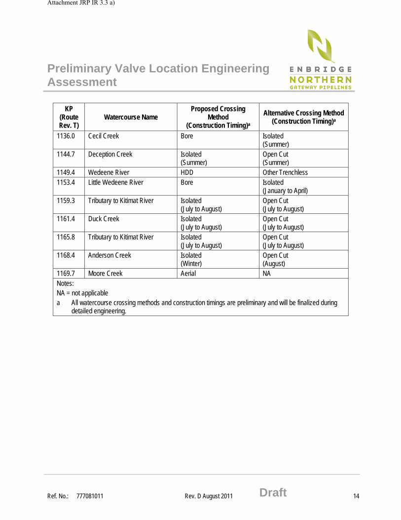
Appendix 2 Watercourse Crossing Methods for Review Sites
KP (Route Rev. T)
Watercourse Name Proposed Crossing
Method (Construction Timing)a
Alternative Crossing Method (Construction Timing)a
4.0 North Saskatchewan River Open Cut (Summer)
Open Cut (Winter)
131.6 Pembina River HDD Isolated (Winter)
138.2 Paddle River Isolated (December to April)
Isolated (Summer)
164.0 Little Paddle River Isolated (December to April)
Isolated (Summer)
187.4 Athabasca River HDD Open Cut (Winter)
200.5 Sakwatamau River Isolated (Winter)
Open Cut (July 16 to August 31)
219.0 Chickadee Creek Isolated (Winter)
Isolated (Summer)
241.8 Two Creek Isolated (Winter)
Isolated (Summer)
259.2 Iosegun River Isolated (Winter)
Isolated (Summer)
272.2 Tributary to Iosegun Lake Open Cut if frozen (November to February)
Isolated (November to February)
272.3 Tributary to Iosegun Lake Open Cut if frozen (November to February)
Isolated (November to February)
272.4 Tributary to Iosegun Lake Open Cut if frozen (November to February)
Isolated (November to February)
272.6 Tributary to Iosegun Lake Open Cut if frozen (November to February)
Isolated (November to February)
274.5 Tributary to Iosegun Lake Open Cut if frozen (November to February)
Isolated (November to February)
275.2 Tributary to Iosegun Lake Open Cut if frozen (November to February)
Isolated (November to February)
291.2 Little Smoky River Isolated (Winter)
Open Cut (July to August)
318.3 Waskahigan River Isolated (Winter)
Isolated (Summer)
Attachment JRP IR 3.3 a)
Preliminary Valve Location Engineering Assessment
Ref. No.: 777081011 Rev. D August 2011 Draft 11
KP (Route Rev. T)
Watercourse Name Proposed Crossing
Method (Construction Timing)a
Alternative Crossing Method (Construction Timing)a
338.9 Deep Valley Creek Isolated (Winter)
Isolated (Summer)
340.9 Tributary to Deep Valley Creek Isolated (Winter)
Isolated (Summer)
360.1 Simonette River Bore Open Cut (July 16 to July 31)
372.0 Latornell River Isolated (Winter)
Isolated (Summer)
395.9 Patterson Creek Isolated (Winter)
Isolated (Summer)
404.5 Tributary to Smoky River Isolated (Winter)
Isolated (Summer)
421.7 Smoky River HDD Open Cut (Winter)
435.7 Big Mountain Creek Isolated (Winter)
Isolated (Summer)
447.3 Bald Mountain Creek Isolated (Winter)
Isolated (Summer)
474.8 Pinto Creek Bore Isolated (Summer)
495.6 Wapiti River HDD Open Cut (November to February)
520.7 Hiding Creek Isolated (December to April)
Isolated (Summer)
534.7 South Redwillow River Isolated (Winter)
Isolated (Summer)
564.3 Kinuseo Creek Isolated (July to August)
Open Cut (July 15 to August 15)
568.8 Kinuseo Creek Isolated (July to August)
Open Cut (July 15 to August 15)
583.7 Five Cabin Creek Isolated (Summer)
Open Cut (July 15 to August 15)
591.0 Kinuseo Creek Bore Open Cut (July 15 to August 15)
599.9 Tributary to Murray River Isolated (July to August)
Open Cut (July August)
Attachment JRP IR 3.3 a)
Preliminary Valve Location Engineering Assessment
Ref. No.: 777081011 Rev. D August 2011 Draft 12
KP (Route Rev. T)
Watercourse Name Proposed Crossing
Method (Construction Timing)a
Alternative Crossing Method (Construction Timing)a
601.4 Murray River Aerial Other Trenchless 605.3 Hook Creek HDD Isolated
(July to August) 622.5 Tributary to Imperial Creek Open Cut
(Anytime) NA
644.0 Missinka River Bore Open Cut (July 15 to August 15)
648.7 Missinka River Open Cut (July 15 to August 15)
NA
674.4 Parsnip River HDD Open Cut (July 15 to August 15)
706.4 Chuchinka Creek Isolated (August)
Open Cut (July 15 to August 15)
713.8 Angusmac Creek Isolated (August)
Open Cut (July 15 to August 15)
721.6 Crooked River Bore Open Cut (July 15 to August 15)
751.4 Muskeg River Bore Isolated (Winter)
766.4 Salmon River Bore Isolated (Winter)
783.7 Tributary to Great Beaver Lake Isolated (Winter)
Isolated (Summer)
819.9 Necoslie River Bore Isolated (Winter)
825.6 Stuart River HDD Other Trenchless 860.0 Sutherland River Isolated
(January to March) Isolated (Summer)
868.0 Tributary to Duncan Creek Isolated (December to April)
Isolated (Summer)
933.1 Endako River Bore Isolated (Winter)
952.0 Maxan Creek Isolated (Summer)
Open Cut (Summer)
964.3 Foxy Creek Isolated (August to March)
Open Cut (August to March)
Attachment JRP IR 3.3 a)
Preliminary Valve Location Engineering Assessment
Ref. No.: 777081011 Rev. D August 2011 Draft 13
KP (Route Rev. T)
Watercourse Name Proposed Crossing
Method (Construction Timing)a
Alternative Crossing Method (Construction Timing)a
968.4 Foxy Creek Isolated (August to March)
Open Cut (August to March)
979.2 Klo Creek Isolated (September to January)
Open Cut (September to January)
990.7 Buck Creek Bore Isolated (Summer)
997.1 Parrott Creek Isolated (August to March)
Open Cut (August to March)
1006.6 Owen Creek Bore Isolated (August to September)
1011.8 Fenton Creek Isolated (August)
Open Cut (August)
1017.5 24.5 Mile Creek Isolated (Summer)
Open Cut (Summer)
1022.5 Lamprey Creek Bore Isolated (August to September)
1029.8 Cedric Creek Isolated (Summer)
Open Cut (Summer)
1042.3 Morice River HDD Other Trenchless 1048.6 Crystal Creek Bore Isolated
(August to September) 1063.2 Gosnell Creek Bore Isolated
(Winter) 1075.6 Tributary to Burnie River Bore Isolated
(August to March) 1076.8 Clore River Bore Isolated
(Winter) 1084.2 Tributary to Clore River Aerial NA 1091.3 Hoult Creek Aerial NA 1103.4 Hunter Creek HDD Isolated
(Winter) 1114.0 Tributary to Kitimat River Open Cut
(Anytime) NA
1127.7 Chist Creek Bore Isolated (January to March)
Attachment JRP IR 3.3 a)
Preliminary Valve Location Engineering Assessment
Ref. No.: 777081011 Rev. D August 2011 Draft 14
KP (Route Rev. T)
Watercourse Name Proposed Crossing
Method (Construction Timing)a
Alternative Crossing Method (Construction Timing)a
1136.0 Cecil Creek Bore Isolated (Summer)
1144.7 Deception Creek Isolated (Summer)
Open Cut (Summer)
1149.4 Wedeene River HDD Other Trenchless 1153.4 Little Wedeene River Bore Isolated
(January to April) 1159.3 Tributary to Kitimat River Isolated
(July to August) Open Cut (July to August)
1161.4 Duck Creek Isolated (July to August)
Open Cut (July to August)
1165.8 Tributary to Kitimat River Isolated (July to August)
Open Cut (July to August)
1168.4 Anderson Creek Isolated (Winter)
Open Cut (August)
1169.7 Moore Creek Aerial NA Notes: NA = not applicable a All watercourse crossing methods and construction timings are preliminary and will be finalized during
detailed engineering.
Attachment JRP IR 3.3 a)
Preliminary Valve Location Engineering Assessment
Ref. No.: 777081011 Rev. D August 2011 Draft 15
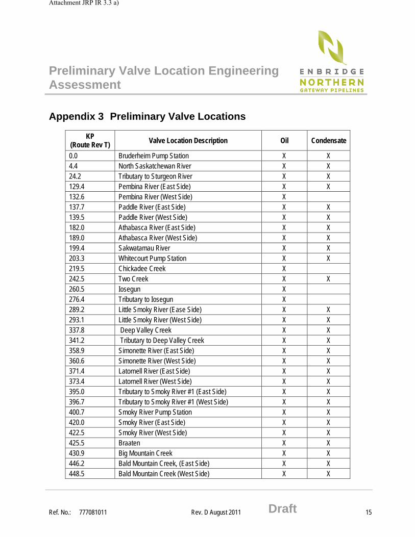
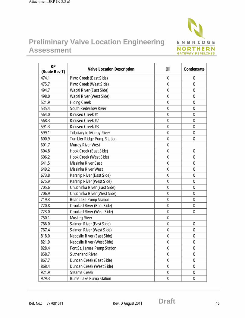
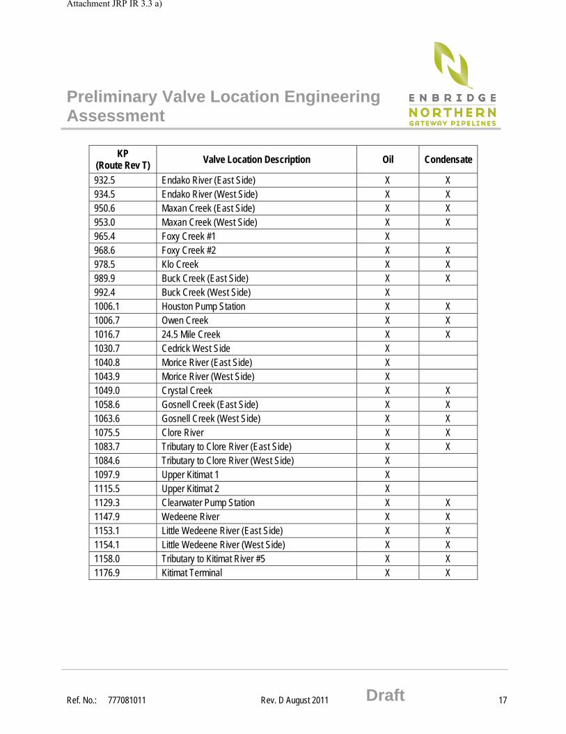
Appendix 3 Preliminary Valve Locations
KP (Route Rev T)
Valve Location Description Oil Condensate
0.0 Bruderheim Pump Station X X 4.4 North Saskatchewan River X X 24.2 Tributary to Sturgeon River X X 129.4 Pembina River (East Side) X X 132.6 Pembina River (West Side) X 137.7 Paddle River (East Side) X X 139.5 Paddle River (West Side) X X 182.0 Athabasca River (East Side) X X 189.0 Athabasca River (West Side) X X 199.4 Sakwatamau River X X 203.3 Whitecourt Pump Station X X 219.5 Chickadee Creek X 242.5 Two Creek X X 260.5 Iosegun X 276.4 Tributary to Iosegun X 289.2 Little Smoky River (Ease Side) X X 293.1 Little Smoky River (West Side) X X 337.8 Deep Valley Creek X X 341.2 Tributary to Deep Valley Creek X X 358.9 Simonette River (East Side) X X 360.6 Simonette River (West Side) X X 371.4 Latornell River (East Side) X X 373.4 Latornell River (West Side) X X 395.0 Tributary to Smoky River #1 (East Side) X X 396.7 Tributary to Smoky River #1 (West Side) X X 400.7 Smoky River Pump Station X X 420.0 Smoky River (East Side) X X 422.5 Smoky River (West Side) X X 425.5 Braaten X X 430.9 Big Mountain Creek X X 446.2 Bald Mountain Creek, (East Side) X X 448.5 Bald Mountain Creek (West Side) X X
Attachment JRP IR 3.3 a)
Preliminary Valve Location Engineering Assessment
Ref. No.: 777081011 Rev. D August 2011 Draft 16
KP (Route Rev T) Valve Location Description Oil Condensate
474.1 Pinto Creek (East Side) X X 475.7 Pinto Creek (West Side) X X 494.7 Wapiti River (East Side) X X 498.0 Wapiti River (West Side) X X 521.9 Hiding Creek X X 535.4 South Redwillow River X X 564.0 Kinuseo Creek #1 X X 568.3 Kinuseo Creek #2 X X 591.3 Kinuseo Creek #3 X X 599.1 Tributary to Murray River X X 600.9 Tumbler Ridge Pump Station X X 601.7 Murray River West X 604.8 Hook Creek (East Side) X X 606.2 Hook Creek (West Side) X X 641.5 Missinka River East X X 649.2 Missinka River West X X 673.8 Parsnip River (East Side) X X 675.9 Parsnip River (West Side) X X 705.6 Chuchinka River (East Side) X X 706.9 Chuchinka River (West Side) X X 719.3 Bear Lake Pump Station X X 720.8 Crooked River (East Side) X X 723.0 Crooked River (West Side) X X 750.1 Muskeg River X 766.0 Salmon River (East Side) X X 767.4 Salmon River (West Side) X X 818.0 Necoslie River (East Side) X X 821.9 Necoslie River (West Side) X X 828.4 Fort St. James Pump Station X X 858.7 Sutherland River X X 867.7 Duncan Creek (East Side) X X 868.4 Duncan Creek (West Side) X X 921.9 Stearns Creek X X 929.3 Burns Lake Pump Station X X
Attachment JRP IR 3.3 a)
Preliminary Valve Location Engineering Assessment
Ref. No.: 777081011 Rev. D August 2011 Draft 17
KP (Route Rev T) Valve Location Description Oil Condensate
932.5 Endako River (East Side) X X 934.5 Endako River (West Side) X X 950.6 Maxan Creek (East Side) X X 953.0 Maxan Creek (West Side) X X 965.4 Foxy Creek #1 X 968.6 Foxy Creek #2 X X 978.5 Klo Creek X X 989.9 Buck Creek (East Side) X X 992.4 Buck Creek (West Side) X 1006.1 Houston Pump Station X X 1006.7 Owen Creek X X 1016.7 24.5 Mile Creek X X 1030.7 Cedrick West Side X 1040.8 Morice River (East Side) X 1043.9 Morice River (West Side) X 1049.0 Crystal Creek X X 1058.6 Gosnell Creek (East Side) X X 1063.6 Gosnell Creek (West Side) X X 1075.5 Clore River X X 1083.7 Tributary to Clore River (East Side) X X 1084.6 Tributary to Clore River (West Side) X 1097.9 Upper Kitimat 1 X 1115.5 Upper Kitimat 2 X 1129.3 Clearwater Pump Station X X 1147.9 Wedeene River X X 1153.1 Little Wedeene River (East Side) X X 1154.1 Little Wedeene River (West Side) X X 1158.0 Tributary to Kitimat River #5 X X 1176.9 Kitimat Terminal X X
Attachment JRP IR 3.3 a)
Preliminary Valve Location Engineering Assessment
Ref. No.: 777081011 Rev. D August 2011 Draft 18
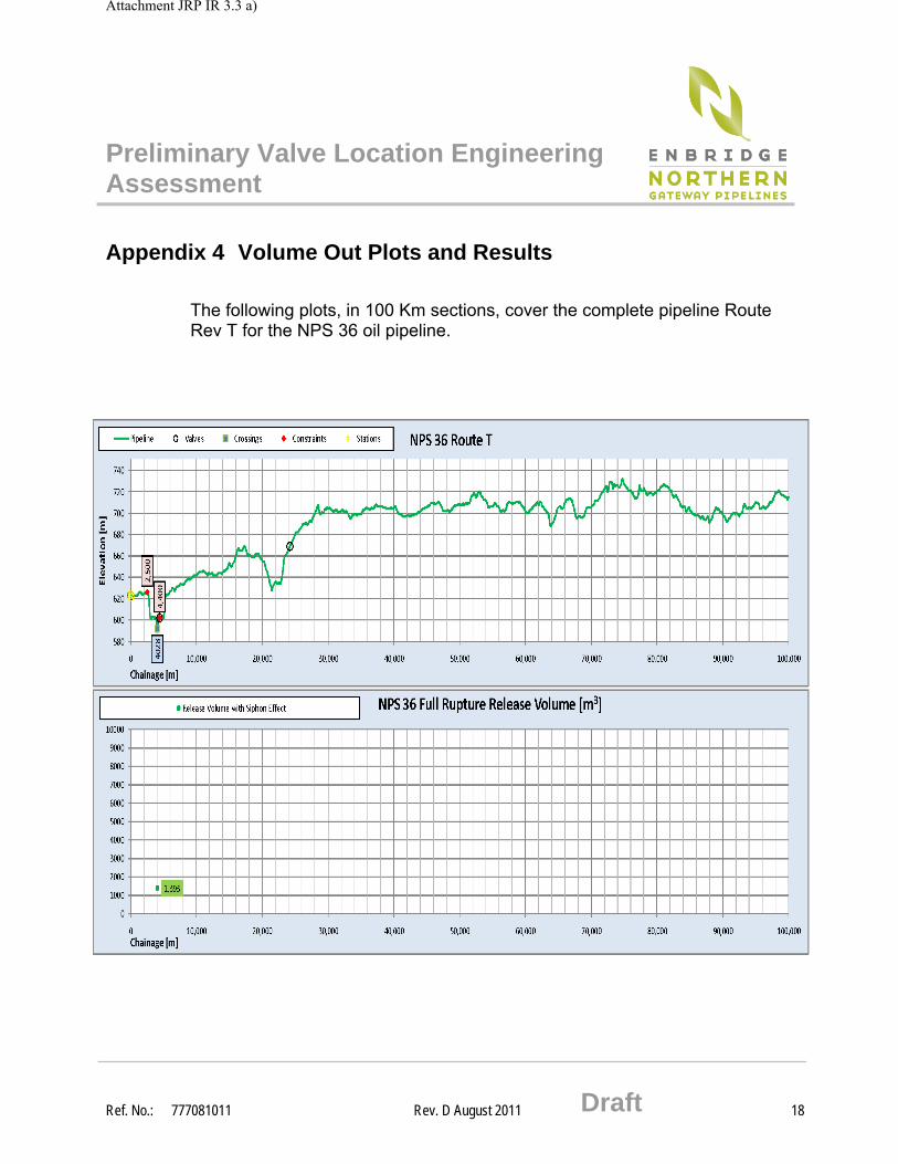
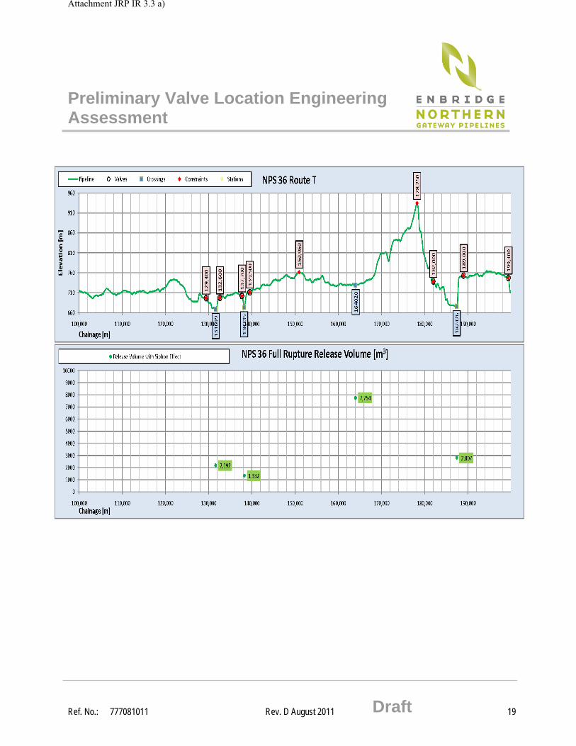
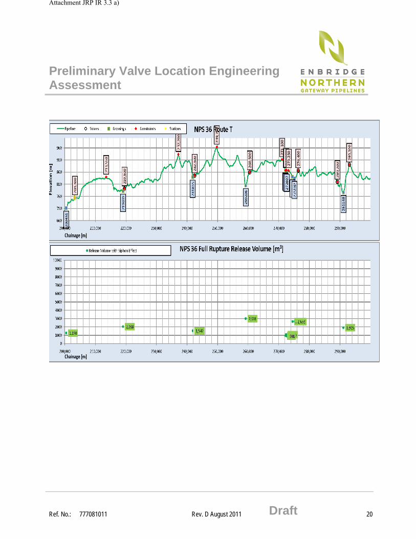
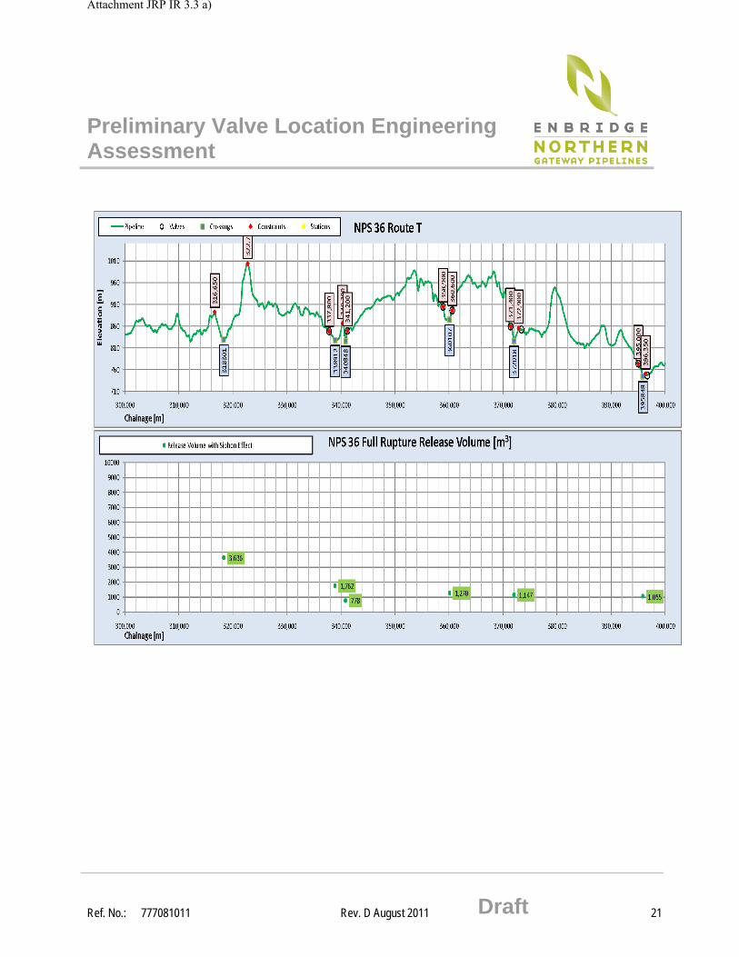
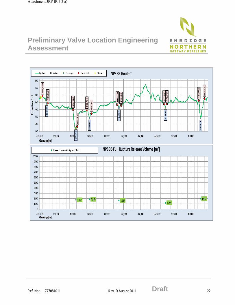
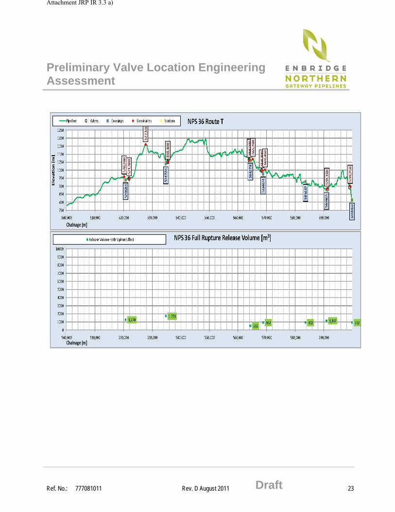
Appendix 4 Volume Out Plots and Results
The following plots, in 100 Km sections, cover the complete pipeline Route Rev T for the NPS 36 oil pipeline.
Attachment JRP IR 3.3 a)
Preliminary Valve Location Engineering Assessment
Ref. No.: 777081011 Rev. D August 2011 Draft 19
Attachment JRP IR 3.3 a)
Preliminary Valve Location Engineering Assessment
Ref. No.: 777081011 Rev. D August 2011 Draft 20
Attachment JRP IR 3.3 a)
Preliminary Valve Location Engineering Assessment
Ref. No.: 777081011 Rev. D August 2011 Draft 21
Attachment JRP IR 3.3 a)
Preliminary Valve Location Engineering Assessment
Ref. No.: 777081011 Rev. D August 2011 Draft 22
Attachment JRP IR 3.3 a)
Preliminary Valve Location Engineering Assessment
Ref. No.: 777081011 Rev. D August 2011 Draft 23
Attachment JRP IR 3.3 a)
Preliminary Valve Location Engineering Assessment
Ref. No.: 777081011 Rev. D August 2011 Draft 24
Attachment JRP IR 3.3 a)
Preliminary Valve Location Engineering Assessment
Ref. No.: 777081011 Rev. D August 2011 Draft 25
Attachment JRP IR 3.3 a)
Preliminary Valve Location Engineering Assessment
Ref. No.: 777081011 Rev. D August 2011 Draft 26
Attachment JRP IR 3.3 a)
Preliminary Valve Location Engineering Assessment
Ref. No.: 777081011 Rev. D August 2011 Draft 27
Attachment JRP IR 3.3 a)
Preliminary Valve Location Engineering Assessment
Ref. No.: 777081011 Rev. D August 2011 Draft 28
Attachment JRP IR 3.3 a)
Preliminary Valve Location Engineering Assessment
Ref. No.: 777081011 Rev. D August 2011 Draft 29
Attachment JRP IR 3.3 a)