Embed Size (px)
Citation preview
PRELIMINARY STUDY ON EMITTANCE GROWTH IN THE LHECRECIRCULATING LINAC∗
Yi-Peng Sun and Chris Adolphsen, SLAC, Menlo Park, USAFrank Zimmermann, CERN, Geneva, Switzerland
Abstract
In this paper, we estimate the emittance growth in theLHeC recirculating Linac, the lattice design of which ispresented in another paper of IPAC10 proceedings. Thepossible sources for emittance growth included here are:energy spread from RF acceleration in the SRF (super-conducting RF) linac together with large chromatic effectsfrom the lattice, and synchrotron radiation (SR) fluctua-tions in the recirculating arcs. 6-D multi-particle trackingis launched to calculate the emittance from the statisticalpoint of view. The simulation results are also comparedwith a theoretical estimation.
INTRODUCTION
The accelerator chain of the LHeC Recirculating Linacconsists of one linac equipped with SRF cavities, two arcsand one transfer line, the lattice design of which is pre-sented in another paper of IPAC10 proceedings [1] [2].
-0.15-0.1
-0.05 0
0.05 0.1
0.15
0 5000 10000 15000 20000 25000
Δβx/
β x (
off-
m)
s [m]
δp=2e-4δp=-2e-4
-0.12-0.08-0.04
0 0.04 0.08 0.12
0 5000 10000 15000 20000 25000
Δβy/
β y (
off-
m) δp=2e-4
δp=-2e-4
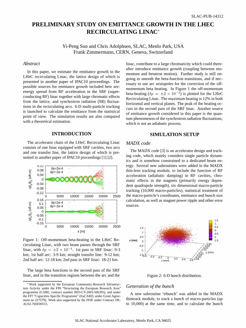
Figure 1: Off-momentum beta-beating in the LHeC Re-circulating Linac, with two beam passes through the SRFlinac, with δp = ±2 × 10⁻⁴. 1st pass in SRF linac: 0-3km; 1st half arc: 3-9 km; straight transfer line: 9-12 km;2nd half arc: 12-18 km; 2nd pass in SRF linac: 18-21 km.
The large beta functions in the second pass of the SRFlinac, and in the transition regions between the arc and the
∗Work supported by the European Community-Research Infrastruc-ture Activity under the FP6 “Structuring the European Research Area”programme (CARE, contract number RII3-CT-2003-506395), and underthe FP7 “Capacities Specific Programme” (EuCARD, under Grant Agree-ment no 227579). Work also supported by the DOE under Contract DE-AC02-76SF00515.
linac, contribute to a large chromaticity which could there-after introduce emittance growth (coupling between mo-mentum and betatron motion). Further study is still on-going to smooth the beta-function transitions, and if nec-essary to use arc sextupoles for the correction of the off-momentum beta beating. In Figure 1 the off-momentumbeta-beating (δp = ±2 × 10⁻⁴) is plotted for the LHeCRecirculating Linac. The maximum beating is 12% in bothhorizontal and vertical planes. The peak of the beating oc-curs in the second pass of the SRF linac. Another sourceof emittance growth considered in this paper is the quan-tum phenomenon of the synchrotron radiation fluctuations,which is not an adiabatic process.
SIMULATION SETUP
MADX code
The MADX code [3] is an accelerator design and track-ing code, which mainly considers single particle dynam-ics and is somehow constrained to a dedicated beam en-ergy. Several new subroutines were added in the MADXthin-lens tracking module, to include the function of RFacceleration (adiabatic damping) in RF cavities, chro-matic effects in the magnets (primarily energy depen-dent quadrupole strength), six dimensional macro-particletracking (10,000 macro-particles), statistical treatment ofthe macro-particle’s coordinates, emittance and bunch sizecalculation, as well as magnet power ripple and other errorsources.
-0.6 -0.4 -0.2 0 0.2 0.4 0.6-0.04-0.03
-0.02-0.01
0 0.01
0.02 0.03
0.04
-1.5
-1
-0.5
0
0.5
1
1.5
s (mm)
x (mm)
y (mm)
s (mm) -1.5-1-0.5 0 0.5 1 1.5
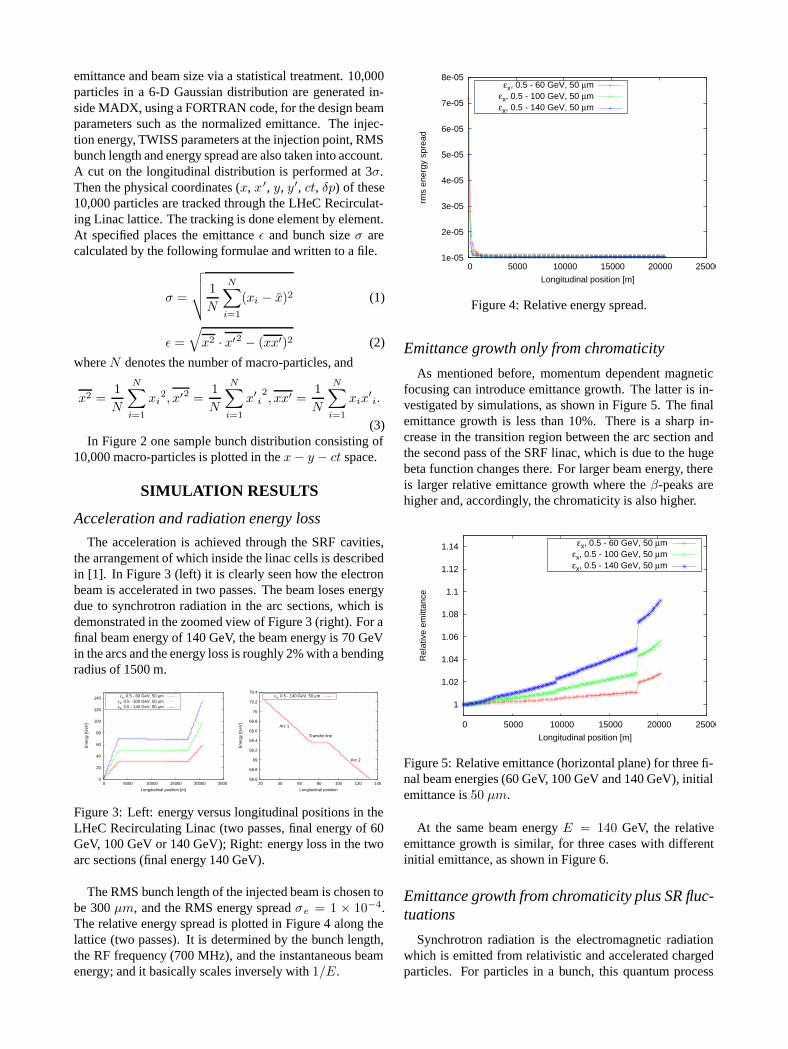
Figure 2: 6-D bunch distribution.
Generation of the bunch
A new subroutine ‘trbunch’ was added in the MADXthintrack module, to track a bunch of macro-particles (upto 10,000) at the same time, and to calculate the bunch
SLAC National Accelerator Laboratory, Menlo Park, CA 94025
SLAC-PUB-14312
emittance and beam size via a statistical treatment. 10,000particles in a 6-D Gaussian distribution are generated in-side MADX, using a FORTRAN code, for the design beamparameters such as the normalized emittance. The injec-tion energy, TWISS parameters at the injection point, RMSbunch length and energy spread are also taken into account.A cut on the longitudinal distribution is performed at 3σ.Then the physical coordinates (x, x′, y, y′, ct, δp) of these10,000 particles are tracked through the LHeC Recirculat-ing Linac lattice. The tracking is done element by element.At specified places the emittance ε and bunch size σ arecalculated by the following formulae and written to a file.
σ =
√√√√
1
N
N∑
i=1
(xi − x̄)2 (1)
ε =
√
x2 · x′2 − (xx′)2 (2)
where N denotes the number of macro-particles, and
x2 =1
N
N∑
i=1
xi2, x′2 =
1
N
N∑
i=1
x′i2, xx′ =
1
N
N∑
i=1
xix′i.
(3)In Figure 2 one sample bunch distribution consisting of
10,000 macro-particles is plotted in the x− y − ct space.
SIMULATION RESULTS
Acceleration and radiation energy loss
The acceleration is achieved through the SRF cavities,the arrangement of which inside the linac cells is describedin [1]. In Figure 3 (left) it is clearly seen how the electronbeam is accelerated in two passes. The beam loses energydue to synchrotron radiation in the arc sections, which isdemonstrated in the zoomed view of Figure 3 (right). For afinal beam energy of 140 GeV, the beam energy is 70 GeVin the arcs and the energy loss is roughly 2% with a bendingradius of 1500 m.
0
20
40
60
80
100
120
140
0 5000 10000 15000 20000 25000
Ene
rgy
[GeV
]
Longitudinal position [m]
εx, 0.5 - 60 GeV, 50 μmεx, 0.5 - 100 GeV, 50 μmεx, 0.5 - 140 GeV, 50 μm
68.6
68.8
69
69.2
69.4
69.6
69.8
70
70.2
70.4
20 40 60 80 100 120 140
Ene
rgy
[GeV
]
Longitudinal position
Arc 1
Transfer line
Arc 2
εx, 0.5 - 140 GeV, 50 μm
Figure 3: Left: energy versus longitudinal positions in theLHeC Recirculating Linac (two passes, final energy of 60GeV, 100 GeV or 140 GeV); Right: energy loss in the twoarc sections (final energy 140 GeV).
The RMS bunch length of the injected beam is chosen tobe 300 μm, and the RMS energy spread σe = 1 × 10⁻⁴.The relative energy spread is plotted in Figure 4 along thelattice (two passes). It is determined by the bunch length,the RF frequency (700 MHz), and the instantaneous beamenergy; and it basically scales inversely with 1/E.
1e-05
2e-05
3e-05
4e-05
5e-05
6e-05
7e-05
8e-05
0 5000 10000 15000 20000 25000
rms
ener
gy s
prea
d
Longitudinal position [m]
εx, 0.5 - 60 GeV, 50 μmεx, 0.5 - 100 GeV, 50 μmεx, 0.5 - 140 GeV, 50 μm
Figure 4: Relative energy spread.
Emittance growth only from chromaticity
As mentioned before, momentum dependent magneticfocusing can introduce emittance growth. The latter is in-vestigated by simulations, as shown in Figure 5. The finalemittance growth is less than 10%. There is a sharp in-crease in the transition region between the arc section andthe second pass of the SRF linac, which is due to the hugebeta function changes there. For larger beam energy, thereis larger relative emittance growth where the β-peaks arehigher and, accordingly, the chromaticity is also higher.
1
1.02
1.04
1.06
1.08
1.1
1.12
1.14
0 5000 10000 15000 20000 25000
Rel
ativ
e em
ittan
ce
Longitudinal position [m]
εx, 0.5 - 60 GeV, 50 μmεx, 0.5 - 100 GeV, 50 μmεx, 0.5 - 140 GeV, 50 μm
Figure 5: Relative emittance (horizontal plane) for three fi-nal beam energies (60 GeV, 100 GeV and 140 GeV), initialemittance is 50 μm.
At the same beam energy E = 140 GeV, the relativeemittance growth is similar, for three cases with differentinitial emittance, as shown in Figure 6.
Emittance growth from chromaticity plus SR fluc-tuations
Synchrotron radiation is the electromagnetic radiationwhich is emitted from relativistic and accelerated chargedparticles. For particles in a bunch, this quantum process
1
1.02
1.04
1.06
1.08
1.1
1.12
1.14
0 5000 10000 15000 20000 25000
Rel
ativ
e em
ittan
ce
Longitudinal position [m]
εx, 0.5 - 140 GeV, 200 μmεx, 0.5 - 140 GeV, 100 μm
εx, 0.5 - 140 GeV, 50 μm
Figure 6: Relative emittance (horizontal plane), E = 140GeV , initial emittance is 50 μm, 100 μm and 200 μm,respectively.
is random. That means when a charged particle passesthrough a dipole magnet and is accelerated orthogonallyto its trajectory, it has a random probability of emittinga photon at any given time. Due to that reason, particleswhich have similar energy and coordinates may lose differ-ent amounts of energy at different times, and this differencein energy change will cause them to follow different trajec-tories and result in beam emittance growth [4].
For an electron beam with energy E and following a tra-jectory with bending radius ρ, the normalized emittancegrowth through the whole arc is [5]
Δγεx = 6.2× 10⁻⁵ GeV−6m2 E6
ρD3F (4)
where Δγεx denotes the normalized emittance growth,D the number of dipole magnets which the beam passesthrough, and F a numerical factor determined by the lat-tice.
1
1.2
1.4
1.6
1.8
2
2.2
2.4
2.6
2.8
3
0 5000 10000 15000 20000 25000
Rel
ativ
e em
ittan
ce
Longitudinal position [m]
εx, 0.5 - 140 GeV, 200 μmεx, 0.5 - 140 GeV, 100 μm
εx, 0.5 - 140 GeV, 50 μm
0.95
1
1.05
1.1
1.15
1.2
1.25
1.3
1.35
0 5000 10000 15000 20000 25000
Rel
ativ
e em
ittan
ce
Longitudinal position [m]
εy, 0.5 - 140 GeV, 200 μmεy, 0.5 - 140 GeV, 100 μm
εy, 0.5 - 140 GeV, 50 μm
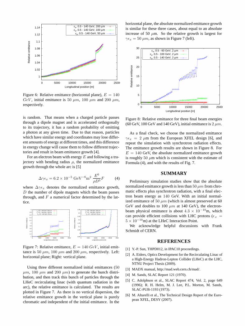
Figure 7: Relative emittance, E = 140 GeV , initial emit-tance is 50 μm, 100 μm and 200 μm, respectively. Left:horizontal plane; Right: vertical plane.
Using three different normalized initial emittances (50μm, 100 μm and 200 μm) to generate the bunch distri-bution, and then track this bunch of particles through theLHeC recirculating linac (with quantum radiation in thearc), the relative emittance is calculated. The results areplotted in Figure 7. As there is no vertical dispersion, therelative emittance growth in the vertical plane is purelychromatic and independent of the initial emittance. In the
horizontal plane, the absolute normalized emittance growthis similar for these three cases, about equal to an absoluteincrease of 50 μm. So the relative growth is largest forγεx = 50 μm, as shown in Figure 7 (left).
0
5
10
15
20
25
30
0 5000 10000 15000 20000 25000
Rel
ativ
e em
ittan
ce
Longitudinal position [m]
εx, 0.5 - 60 GeV, 2 μmεx, 0.5 - 100 GeV, 2 μmεx, 0.5 - 140 GeV, 2 μm
Figure 8: Relative emittance for three final beam energies(60 GeV, 100 GeV and 140 GeV), initial emittance is 2 μm.
As a final check, we choose the normalized emittanceγεx = 2 μm from the European XFEL design [6], andrepeat the simulation with synchrotron radiation effects.The emittance growth results are shown in Figure 8. ForE = 140 GeV, the absolute normalized emittance growthis roughly 50 μm which is consistent with the estimate ofFormula (4), and with the results of Fig. 7.
SUMMARY
Preliminary simulation studies show that the absolutenormalized emittance growth is less than 50 μm from chro-matic effects plus synchrotron radiation, with a final elec-tron beam energy as 140 GeV. With an initial normal-ized emittance of 50 μm (which is almost preserved at 60GeV and doubles to 100 μm at 140 GeV), the electron-beam physical emittance is about 4.3 × 10⁻¹⁰m, whichcan provide efficient collisions with LHC protons (εx =5× 10⁻¹⁰m) at the LHeC Interaction Point.
We acknowledge helpful discussions with FrankSchmidt of CERN.
REFERENCES
[1] Y.-P. Sun, THPD012, in IPAC10 proceedings.
[2] A. Eiders, Optics Development for the Recirculating Linac ofa High-Energy Hadron-Lepton Collider (LHeC) at the LHC,NTNU Project Thesis (2009).
[3] MADX manual, http://mad.web.cern.ch/mad/.
[4] M. Sands, SLAC Report 121 (1970).
[5] C. Adolphsen et al., SLAC Report 474, Vol. 2, page 649(1996); R. H. Helm, M. J. Lee, P.L. Morton, M. Sands,SLAC-PUB-1193 (1973).
[6] M. Altarelli et al., The Technical Design Report of the Euro-pean XFEL, DESY (2007).