Embed Size (px)
Citation preview
PRELIMINARY MUNICIPAL
SERVICING REPORT
NORTHWOODS SUBDIVISION
Prepared for: North Grassie Properties Inc.
Prepared by:
Stantec Consulting Ltd.
905 Waverley St.
Winnipeg, MB R3T 5P4
July 2012
File: 116808030
PRELIMINARY MUNICIPAL SERVICING REPORT
NORTHWOODS SUBDIVISION
\\cd1201-f02\work_group\1168\active\116808030\northwoods\rpt_municipalservicing_northwoods_jul1912.doc i
Table of Contents
1.0 INTRODUCTION ................................................................................................................ 1
2.0 WATER SYSTEM ............................................................................................................... 2
3.0 WASTEWATER SEWER SYSTEM .................................................................................... 4
4.0 LAND DRAINAGE SEWER ................................................................................................ 5
4.1 BACKGROUND .................................................................................................................. 5
4.2 DESIGN CRITERIA AND DETAILED ANALYSIS ................................................................ 5 4.2.1 Retention Lakes ................................................................................................... 6 4.2.2 Land Drainage Sewers ......................................................................................... 6
LIST OF FIGURES
Figure 2.1 – Water Supply Concept
Figure 3.1 – Wastewater Sewer Concept
Figure 4.1 – Land Drainage Sewer Concept

PRELIMINARY MUNICIPAL SERVICING REPORT
NORTHWOODS
\\cd1201-f02\work_group\1168\active\116808030\northwoods\rpt_municipalservicing_northwoods_jul1912.doc 1
1.0 Introduction
This brief has been prepared for submission to the City of Winnipeg as a requirement of their
development review and subsequent approval on behalf of the developer, North Grassie
Properties Inc. The brief covers the conceptual servicing options for this proposed subdivision.
The proposed development encompasses approximately 77.4 hectares and is ultimately
bounded:
- on the north by Gunn Road,
- on the east by the Perimeter Highway,
- on the south by a Hydro Transmission Line ROW and the Cordite Drain.
- and on the west by a Hydro Transmission Line ROW.
PRELIMINARY MUNICIPAL SERVICING REPORT
NORTHWOODS
\\cd1201-f02\work_group\1168\active\116808030\northwoods\rpt_municipalservicing_northwoods_jul1912.doc 2
2.0 Water System
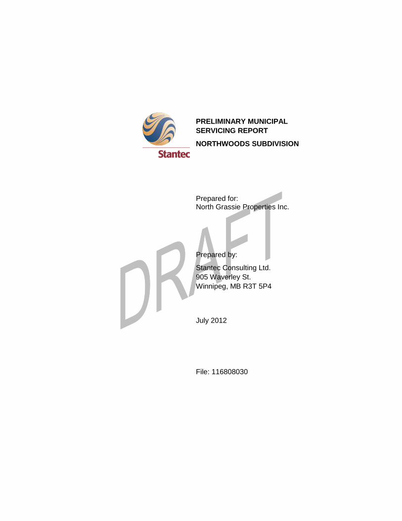
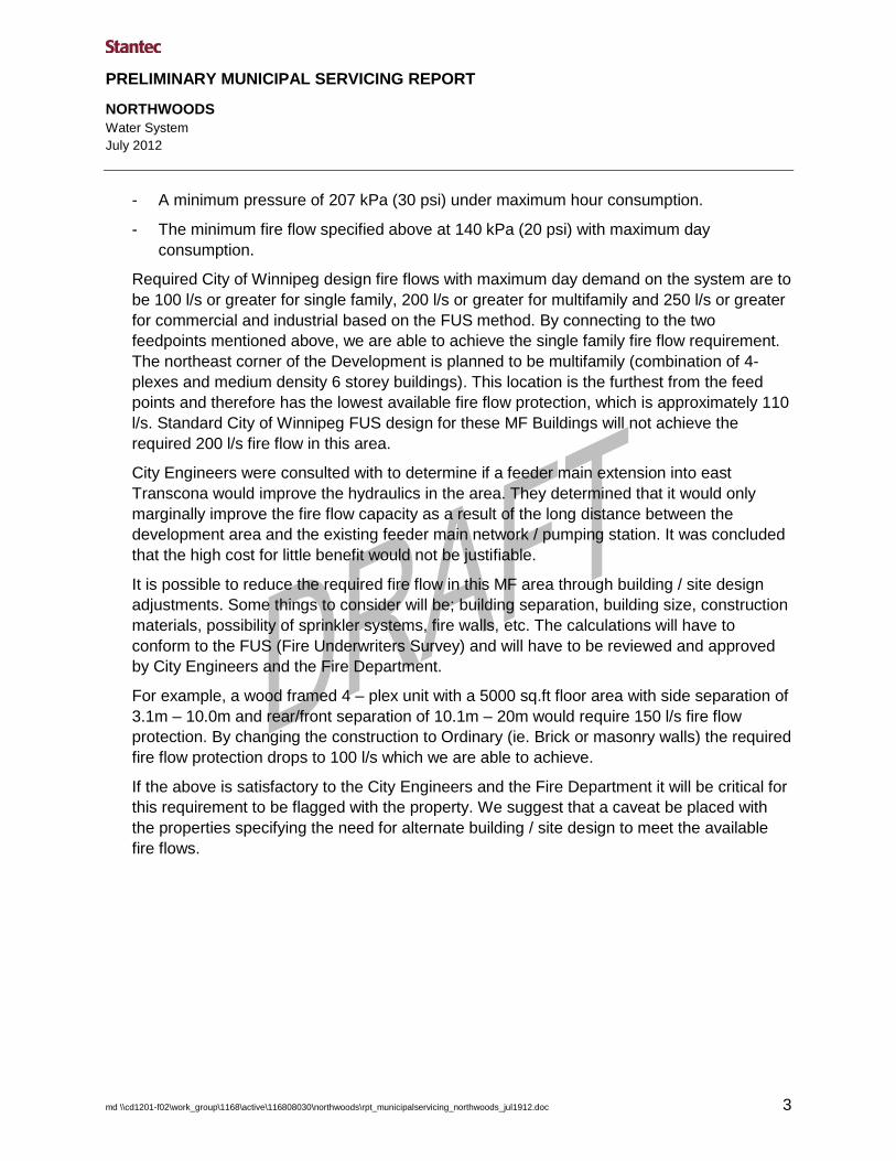
The water service area is shown on Figure 2.1. The system will have two feedpoints that are
located at:
- Redonda Street and Paulley Drive off an existing 250 watermain,
- Fairview Drive and Millbrook Road off an existing 150 watermain.
The systems performance was analyzed under various operating conditions using EPA NET
2.0, a computer simulation program produced by the Environmental Protection Agency (EPA).
For our analysis, the City of Winnipeg’s Water and Waste Department provided us with
simulated conditions at the above feedpoints that were inputted into our model. The simulated
feedpoint pressures were representative of maximum day demand conditions in the distribution
system.
The following design criteria and assumptions were used in the analysis of the watermains:
1. Hazen-Williams coefficient of friction (“C” value) for all pipe diameters was assumed to
be 120.
2. Population based on 3.05 persons per single family dwelling unit and 2.30 persons per
multi family dwelling unit.
3. The number of dwelling units served by each node was calculated based on the concept
plan shown in Figure 2.1.
4. The average daily per capita consumption used was 270 L.
5. The assumed peak daily consumption for:
- Commercial is 28,100 l/day/ha.
- Industrial is 37,600 l/day/ha.
6. The maximum day demand used was 1.6 x average day rate.
7. The peak hour multiplier used was 2.5.
8. For analysis purposes, the watermains were assumed to be at a constant elevation
considering the subdivision’s ground elevations vary slightly. The watermain system was
tied into feedpoint nodes where simulated hydrant flow test data was provided by the
City of Winnipeg.
9. Hydrant losses were accounted for by calculating available fire flows using 25 psi as
opposed to 20 psi.
Based on the above conditions, the proposed watermain system can meet the required
operating criteria of:
PRELIMINARY MUNICIPAL SERVICING REPORT
NORTHWOODS
Water System
July 2012
md \\cd1201-f02\work_group\1168\active\116808030\northwoods\rpt_municipalservicing_northwoods_jul1912.doc 3
- A minimum pressure of 207 kPa (30 psi) under maximum hour consumption.
- The minimum fire flow specified above at 140 kPa (20 psi) with maximum day
consumption.
Required City of Winnipeg design fire flows with maximum day demand on the system are to
be 100 l/s or greater for single family, 200 l/s or greater for multifamily and 250 l/s or greater
for commercial and industrial based on the FUS method. By connecting to the two
feedpoints mentioned above, we are able to achieve the single family fire flow requirement.
The northeast corner of the Development is planned to be multifamily (combination of 4-
plexes and medium density 6 storey buildings). This location is the furthest from the feed
points and therefore has the lowest available fire flow protection, which is approximately 110
l/s. Standard City of Winnipeg FUS design for these MF Buildings will not achieve the
required 200 l/s fire flow in this area.
City Engineers were consulted with to determine if a feeder main extension into east
Transcona would improve the hydraulics in the area. They determined that it would only
marginally improve the fire flow capacity as a result of the long distance between the
development area and the existing feeder main network / pumping station. It was concluded
that the high cost for little benefit would not be justifiable.
It is possible to reduce the required fire flow in this MF area through building / site design
adjustments. Some things to consider will be; building separation, building size, construction
materials, possibility of sprinkler systems, fire walls, etc. The calculations will have to
conform to the FUS (Fire Underwriters Survey) and will have to be reviewed and approved
by City Engineers and the Fire Department.
For example, a wood framed 4 – plex unit with a 5000 sq.ft floor area with side separation of
3.1m – 10.0m and rear/front separation of 10.1m – 20m would require 150 l/s fire flow
protection. By changing the construction to Ordinary (ie. Brick or masonry walls) the required
fire flow protection drops to 100 l/s which we are able to achieve.
If the above is satisfactory to the City Engineers and the Fire Department it will be critical for
this requirement to be flagged with the property. We suggest that a caveat be placed with
the properties specifying the need for alternate building / site design to meet the available
fire flows.

PRELIMINARY MUNICIPAL SERVICING REPORT
NORTHWOODS
\\cd1201-f02\work_group\1168\active\116808030\northwoods\rpt_municipalservicing_northwoods_jul1912.doc 4
3.0 Wastewater Sewer System
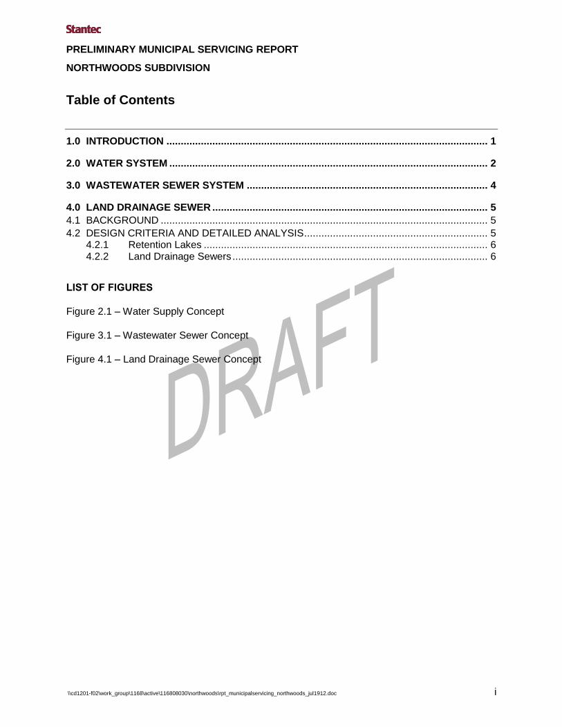
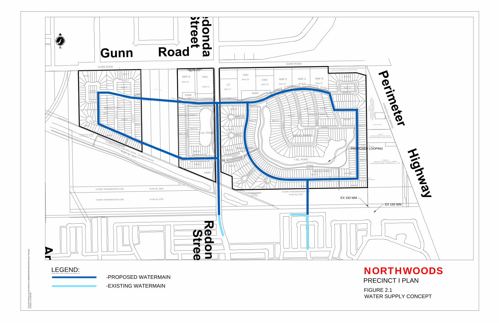
The proposed development is located in a new proposed Sewer District north of the Transcona
Sewer District that will discharge to a new 750 mm Interceptor sewer that will be extended north
on Plessis Rd. from the intersection of Plessis & Devonshire. The proposed Interceptor would
turn east on Gunn Rd. and terminate at Day St. North Grassie Properties will be responsible to
extend a wastewater sewer from the Development and tie it into the Interceptor. This sewer
district will be conveyed to the North End Pollution Control Centre via existing Interceptor
Sewers.
A schematic of the wastewater sewer system for this Development is shown in Figure 3.1.
The design criteria below will be used to design wastewater sewer system for this Development:
1. Peak Design Flow = domestic sewage x peaking factor plus extraneous flow.
The extraneous flows include groundwater infiltration and manhole cover inflow.
2. Domestic Sewage (Residential)
Average Flow: 270 L/capita/day
Peaking Factor: Harman’s = 1 + 14/(4+p0.5)
Population/dwelling = 3.05 persons (single family)
= 2.30 persons (multi family)
Dwelling Density = based on single family lotting plan and densities provided by planners
for Multi Family
3. Peak Commercial Flow: 28,100 L/ha/day
Peak Light Industrial Flow: 37,600 L/ha/day
4. Extraneous Flow
a) Groundwater Infiltration: 2200 L/ha/day
b) Manhole Infiltration: 12 L/min/manhole
Manhole Spacing: 1.6 Manholes/ha
5. Pipe selection was based on full flow pipe with Manning’s N = 0.013 and minimum velocity
of 0.6 m/sec (2.0 ft/sec). Adequate pipe cover and slope will be demonstrated on the
detailed design drawings.

PRELIMINARY MUNICIPAL SERVICING REPORT
NORTHWOODS
\\cd1201-f02\work_group\1168\active\116808030\northwoods\rpt_municipalservicing_northwoods_jul1912.doc 5
4.0 Land Drainage Sewer
4.1 BACKGROUND
The proposed 77.4 hectare development is located within Area F of the Bunn’s Creek Drainage Area.
4.2 DESIGN CRITERIA AND DETAILED ANALYSIS
4.2.1 Retention Lakes
The specific City of Winnipeg criteria guidelines applicable to the Retention Lakes are as
follows:
- 1.22 m lake rise for a 25 year storm (maximum).
- Freeboard Elevation (0.90 m above 100 year level)
- 4:1 side slopes below water and 7:1 side slopes above normal water level and 3.0 m
horizontally into the water.
- 2.5 m water depth.
The typical retention lake cross section is as follows:
InfoWorks CS software will be used to simulate the City of Winnipeg 25 yr, 100 yr and the May
2010 design storms on the Retention Lakes and interconnecting pipe system to confirm the
storage availability and operation of the system.

PRELIMINARY MUNICIPAL SERVICING REPORT
NORTHWOODS
Land Drainage Sewer
July 2012
md \\cd1201-f02\work_group\1168\active\116808030\northwoods\rpt_municipalservicing_northwoods_jul1912.doc 6
The retention lake will be modeled as storage nodes with 7H:1V side slopes from 0.43m below
the normal water level up to 1.5 m above N.W.L. The N.W.L. elevation in the retention lakes will
be maintained by a Weir in a Manhole.
For this model, the retention lake and the interconnecting land drainage sewers were configured
and run in the EXTRAN block and the subcatchments were run in the RUNOFF block.
The Rainfall / Intensity Values for the 25 and 100 year storms were calculated by the following Intensity Duration Formulas:
i 25yr = 72.5
(MacLaren 1974) (t + 9) ^ 0.842
i 100yr = 91.28
(Acres 1978) (t + 8) ^ 0.8555
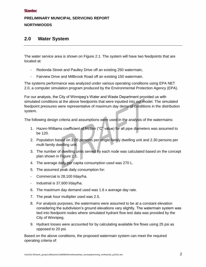
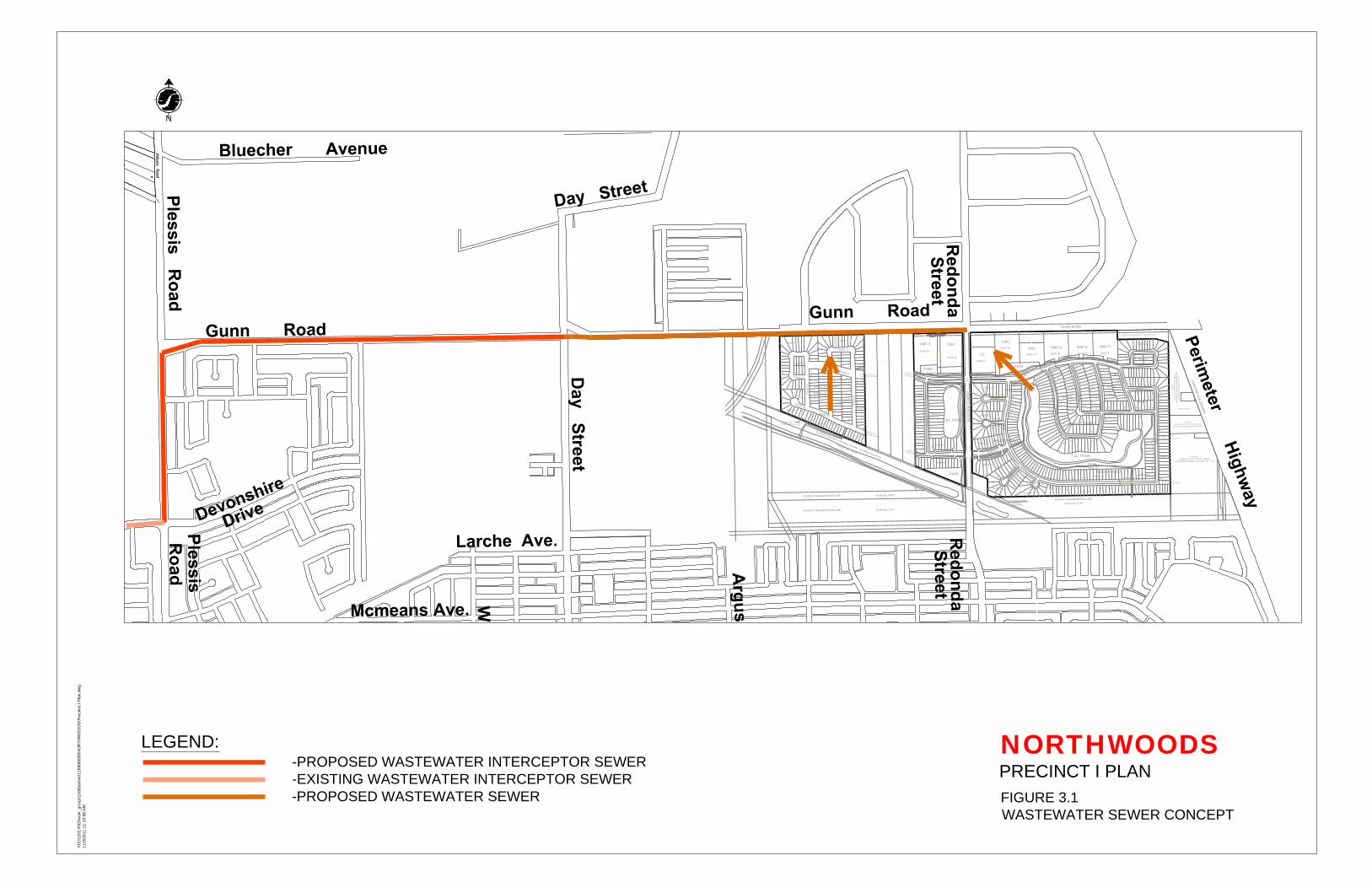
In discussions with City Engineers, it was decided that two options would be evaluated for storm
water discharge. The first option would look at discharging to the Cordite Drain either by gravity
or pumping. The second option would look at discharging by gravity via an outfall pipe to the
Floodway on the east side of the Perimeter Highway. These options will be evaluated in detail
during the design phase of this project
4.2.2 Land Drainage Sewers
This section details the design criteria, parameters, and assumptions that will be used in the
design of the land drainage sewers for this Development. The piped system will be designed
using the Rational Design method and will be based on the following criteria:
5 year storm intensity equation I = 47.2/(t+8)0.828 ---> (MacLaren 1974).
Pipe friction factor (Manning’s n): 0.013 (Concrete and PVC).
Minimum full flow velocity: 3 ft /s.
Maximum full flow velocity: 10 ft /s.
The 1:5 year return frequency was used for the design of the storm sewer system.
Runoff Design Criteria
The rational design method was used to estimate rainfall runoff to be handled by the piped
system:
Q = CiA
Where:

PRELIMINARY MUNICIPAL SERVICING REPORT
NORTHWOODS
Land Drainage Sewer
July 2012
md \\cd1201-f02\work_group\1168\active\116808030\northwoods\rpt_municipalservicing_northwoods_jul1912.doc 7
Q = runoff (CFS)
C = runoff coefficient
i = rainfall intensity (in/hr)
A = area (acres)
The drainage catchments will include single family, multi-family and commercial zoning, which
reflect runoff coefficients (“C” values) of 0.50, 0.70 and 0.70, respectively.
System Design Criteria
The land drainage sewers in this subdivision will be designed as surcharged pipe systems that
will accommodate the calculated runoffs. The surcharge level of the system will be designed to
be at a minimum of 0.15m below the proposed gutter elevations. The Manning’s Equation with
an N = 0.013 for concrete or PVC pipe will be used to determine pipe sizes and hydraulic losses
within the system.
GUNN ROAD
C
L
O
S
E
D
W
A
T
E
R
C
O
N
T
R
O
L
W
O
R
K
(
C
O
R
D
I
T
E
D
I
T
C
H
)
P
L
A
N
N
o
.
8
2
5
1
GUNN ROAD
HYDRO TRANSMISSION LINE
PLAN No. 5787
P
E
R
I
M
E
T
E
R
H
I
G
H
W
A
Y
RE
DO
ND
A S
TR
EE
T
LAND TO BE ACQUIRED BY HMQ MANITOBA
5.32± AC.
CE
RT
IF
IC
AT
E O
F T
IT
LE
N
o. 986847
RE
GIS
TE
RE
D O
WN
ER
: H
MQ
M
AN
IT
OB
A
(S
UB
JE
CT
T
O R
IG
HT
O
F W
AY
)
2.82± AC.
CERTIFICATE OF TITLE No. 987472
REGISTERED OWNER: HMQ MANITOBA
RIGHT OF WAY
HYDRO TRANSMISSION LINEPLAN No. 6604
1
2
3
4
P
L
A
N
N
o
. 2
2
1
5
2
HYDRO TRANSMISSION LINEPLAN No. 5787
SINGLE FAMILY
PARK
SINGLE FAMILY
C2
SINGLE FAMILY
7 AC. POND
PARK
SINGLE FAMILY
SINGLE FAMILY
block 4
block 1
block 2
block 3
block 5
block 6
block 7
block 12
block 8
block 9
block 11
block 13
block 15
block 16
block 26
block 23
block 27
block 35
block 28
block 25block 29
block 32
block 36
block 39
SINGLE FAMILY
block 37
CMU
CMU
RMF-S
block 17
block 18
block 19
block 20
RMF-S
CMU
block 34
CONNECTION TO
FUTURE DEVELOPMENT
CONNECTION TO
FUTURE DEVELOPMENT
C
O
N
N
E
C
T
IO
N
T
O
F
U
T
U
R
E
D
E
V
E
L
O
P
M
E
N
T
CONNECTION TO
FUTURE DEVELOPMENT
SIGNALIZED
INTERSECTION
block 33
block 41
block 40
R
O
A
D
1
RO
AD
2
RO
AD
3
RO
AD
4
RO
AD
5
ROAD 6
R
O
A
D
9
R
O
A
D
1
0
R
O
A
D
1
1
ROAD 14
ROAD 15
ROAD 16
RO
AD
21
ROAD 19
R
O
A
D
2
0
R
O
A
D
1
6
R
O
A
D
1
8
RO
AD
12
block 24
block 30
block 31
RO
AD
2
ROAD 7
ROAD 8
RMF-S
RMF-S
PARK
CONNECTION TO
FUTURE DEVELOPMENT
block 38
C
O
N
N
E
C
T
IO
N
T
O
F
U
T
U
R
E
D
E
V
E
L
O
P
M
E
N
T
C
O
N
N
E
C
T
IO
N
T
O
F
U
T
U
R
E
D
E
V
E
L
O
P
M
E
N
T
block 10
block 14
block 21block 22
block 43
block 42
3 AC. POND
PARK
TE
MP
OR
AR
Y A
CC
ES
S
TO
G
UN
N R
OA
D
PARK
PARK
PARK
PARK
PARK
RO
AD
2
2
RO
AD
23
RO
AD
24
ROAD 25
R
O
A
D
2
6
ROAD 17
PARK
FIGURE 2.1
WATER SUPPLY CONCEPT
NORTHWOODSPRECINCT I PLAN
\\C
D1
20
1-F
02
\w
ork_
gro
up
\1
16
8\a
ctive
\1
16
80
80
30
\N
OR
TH
WO
OD
S\P
re
cin
ct I P
la
n.d
wg
11
/3
/2
01
1 1
1:1
0:3
8 A
M
N
LEGEND:
-PROPOSED WATERMAIN
-EXISTING WATERMAIN
PROPOSED LOOPING
EX 150 WM
EX 150 WM
GUNN ROAD
C
L
O
S
E
D
W
A
T
E
R
C
O
N
T
R
O
L
W
O
R
K
(
C
O
R
D
I
T
E
D
I
T
C
H
)
P
L
A
N
N
o
.
8
2
5
1
GUNN ROAD
HYDRO TRANSMISSION LINE
PLAN No. 5787
P
E
R
I
M
E
T
E
R
H
I
G
H
W
A
Y
RE
DO
ND
A S
TR
EE
T
LAND TO BE ACQUIRED BY HMQ MANITOBA
5.32± AC.
CE
RT
IF
IC
AT
E O
F T
IT
LE
N
o. 986847
RE
GIS
TE
RE
D O
WN
ER
: H
MQ
M
AN
IT
OB
A
(S
UB
JE
CT
T
O R
IG
HT
O
F W
AY
)
2.82± AC.
CERTIFICATE OF TITLE No. 987472
REGISTERED OWNER: HMQ MANITOBA
RIGHT OF WAY
HYDRO TRANSMISSION LINE PLAN No. 6604
1
2
3
4
P
LA
N
N
o. 22152
HYDRO TRANSMISSION LINEPLAN No. 5787
SINGLE FAMILY
PARK
SINGLE FAMILY
C2
SINGLE FAMILY
7 AC. POND
PARK
SINGLE FAMILY
SINGLE FAMILY
block 4
block 1
block 2
block 3
block 5
block 6
block 7
block 12
block 8
block 9
block 11
block 13
block 15
block 16
block 26
block 23
block 27
block 35
block 28
block 25 block 29
block 32
block 36
block 39
SINGLE FAMILY
block 37
CMU
CMU
RMF-S
block 17
block 18
block 19
block 20
RMF-S
CMU
block 34
CONNECTION TO
FUTURE DEVELOPMENT
CONNECTION TO
FUTURE DEVELOPMENT
C
O
N
N
E
C
T
IO
N
T
O
F
U
T
U
R
E
D
E
V
E
L
O
P
M
E
N
T
CONNECTION TO
FUTURE DEVELOPMENT
SIGNALIZED
INTERSECTION
block 33
block 41
block 40
R
O
A
D
1
RO
AD
2
RO
AD
3
RO
AD
4
RO
AD
5
ROAD 6
R
O
A
D
9
R
O
A
D
1
0
R
O
A
D
1
1
ROAD 14
ROAD 15
ROAD 16
RO
AD
21
ROAD 19
R
O
A
D
2
0
R
O
A
D
1
6
R
O
A
D
1
8
RO
AD
12
block 24
block 30
block 31
RO
AD
2
ROAD 7
ROAD 8
RMF-S
RMF-S
PARK
CONNECTION TO
FUTURE DEVELOPMENT
block 38
C
O
N
N
E
C
T
IO
N
T
O
F
U
T
U
R
E
D
E
V
E
L
O
P
M
E
N
T
C
O
N
N
E
C
T
IO
N
T
O
F
U
T
U
R
E
D
E
V
E
L
O
P
M
E
N
T
block 10
block 14
block 21block 22
block 43
block 42
3 AC. POND
PARK
TE
MP
OR
AR
Y A
CC
ES
S
TO
G
UN
N R
OA
D
PARK
PARK
PARK
PARK
PARK
RO
AD
22
RO
AD
23
RO
AD
24
ROAD 25
R
O
A
D
2
6
ROAD 17
PARK
FIGURE 3.1
WASTEWATER SEWER CONCEPT
NORTHWOODSPRECINCT I PLAN
\\C
D1
20
1-F
02
\w
ork_
gro
up
\1
16
8\a
ctive
\1
16
80
80
30
\N
OR
TH
WO
OD
S\P
re
cin
ct I P
la
n.d
wg
11
/3
/2
01
1 1
1:1
0:3
8 A
M
N
LEGEND:
-PROPOSED WASTEWATER INTERCEPTOR SEWER
-EXISTING WASTEWATER INTERCEPTOR SEWER
-PROPOSED WASTEWATER SEWER
GUNN ROAD
C
L
O
S
E
D
W
A
T
E
R
C
O
N
T
R
O
L
W
O
R
K
(
C
O
R
D
I
T
E
D
I
T
C
H
)
P
L
A
N
N
o
.
8
2
5
1
GUNN ROAD
HYDRO TRANSMISSION LINE
PLAN No. 5787
P
E
R
I
M
E
T
E
R
H
I
G
H
W
A
Y
RE
DO
ND
A S
TR
EE
T
LAND TO BE ACQUIRED BY HMQ MANITOBA
5.32± AC.
CE
RT
IF
IC
AT
E O
F T
IT
LE
N
o. 986847
RE
GIS
TE
RE
D O
WN
ER
: H
MQ
M
AN
IT
OB
A
(S
UB
JE
CT
T
O R
IG
HT
O
F W
AY
)
2.82± AC
.
CERTIFICATE OF TITLE No. 987472
REGISTERED OWNER: HMQ MANITOBA
RIGHT OF WAY
HYDRO TRANSMISSION LINE PLAN No. 6604
1
2
3
4
P
L
A
N
N
o
. 2
2
1
5
2
HYDRO TRANSMISSION LINEPLAN No. 5787
SINGLE FAMILY
PARK
SINGLE FAMILY
C2
SINGLE FAMILY
7 AC. POND
PARK
SINGLE FAMILY
SINGLE FAMILY
block 4
block 1
block 2
block 3
block 5
block 6
block 7
block 12
block 8
block 9
block 11
block 13
block 15
block 16
block 26
block 23
block 27
block 35
block 28
block 25block 29
block 32
block 36
block 39
SINGLE FAMILY
block 37
CMU
CMU
RMF-S
block 17
block 18
block 19
block 20
RMF-S
CMU
block 34
CONNECTION TO
FUTURE DEVELOPMENT
CONNECTION TO
FUTURE DEVELOPMENT
C
O
N
N
E
C
T
IO
N
T
O
F
U
T
U
R
E
D
E
V
E
L
O
P
M
E
N
T
CONNECTION TO
FUTURE DEVELOPMENT
SIGNALIZED
INTERSECTION
block 33
block 41
block 40
R
O
A
D
1
RO
AD
2
RO
AD
3
RO
AD
4
RO
AD
5
ROAD 6
R
O
A
D
9
R
O
A
D
1
0
R
O
A
D
1
1
ROAD 14
ROAD 15
ROAD 16
RO
AD
21
ROAD 19
R
O
A
D
2
0
R
O
A
D
1
6
R
O
A
D
1
8
RO
AD
12
block 24
block 30
block 31
RO
AD
2
ROAD 7
ROAD 8
RMF-S
RMF-S
PARK
CONNECTION TO
FUTURE DEVELOPMENT
block 38
C
O
N
N
E
C
T
IO
N
T
O
F
U
T
U
R
E
D
E
V
E
L
O
P
M
E
N
T
C
O
N
N
E
C
T
IO
N
T
O
F
U
T
U
R
E
D
E
V
E
L
O
P
M
E
N
T
block 10
block 14
block 21
block 22
block 43
block 42
3 AC. POND
PARK
TE
MP
OR
AR
Y A
CC
ES
S
TO
G
UN
N R
OA
D
PARK
PARK
PARK
PARK
PARK
RO
AD
2
2
RO
AD
2
3
RO
AD
24
ROAD 25
R
O
A
D
2
6
ROAD 17
PARK
TO FLOODWAY
FIGURE 4.1
LAND DRAINAGE SEWER CONCEPT
NORTHWOODSPRECINCT I PLAN
\\C
D1
20
1-F
02
\w
ork_
gro
up
\1
16
8\a
ctive
\1
16
80
80
30
\N
OR
TH
WO
OD
S\P
re
cin
ct I P
la
n.d
wg
11
/3
/2
01
1 1
1:1
0:3
8 A
M
N
LEGEND:
-PROPOSED LAND DRAINAGE SEWER
OUTLET TO CORDITE DRAIN
-OUTFALL OPTION #1
-OUTFALL OPTION #2


![Blastomycosis - A Northwoods Nuisance · Blastomycosis - A Northwoods Nuisance Lake Tides ... Photo courtesy of John Archer Photo courtesy of John Archer [Blastomycosis] is treatable,](https://img.pdfslide.us/doc/110x75/5b8fe87009d3f27a6d8d0c4a/blastomycosis-a-northwoods-nuisance-blastomycosis-a-northwoods-nuisance.jpg)