Embed Size (px)
Citation preview

May 2016
UNIVERSITY OF HELSINKI - DEPARTMENT OF CHEMISTRY – LABORATORY OF RADIOCHEMISTRY UNIVERSITÉ DE LILLE I
MASTER OF SCIENCE “ADVANCED SPECTROSCOPY IN CHEMISTRY”
Preliminary Investigation of
Rare Earth Elements Ion Exchange on
Zeolites
- MASTER THESIS -
Lucie Duplouy
Supervisor: Dr. Risto Harjula Reviewer: Pr. Sylvain Cristol

1
ABSTRACT
Found together in nature, the isolation of rare earth elements (REEs) has always been
challenging. Their separation usually involves processes including solvent extraction,
precipitation and ion exchange. Zeolites are well-known for their ion exchange capabilities that
would be potentially applicable for the REEs separation. This study primarily investigated the ion
exchange behavior of REEs onto several types of zeolites, namely the Ferrierite, the Faujasite and
the Linde Type L. These zeolites were chosen because of their altered framework type and
controllable charge density through synthesis. The commercially available zeolites were
systematically characterized by means of X-Ray Diffraction (XRD), Energy Dispersive X-ray
spectroscopy (EDX) and Attenuated Total Reflectance Fourier Transform Infrared spectroscopy
(ATR-FTIR). Lanthanum was chosen as the model REE. The pH-uptake behavior of La on zeolites
was studied extensively. Results showed that among all our selected zeolites, only LTL gave
reasonable amount of La ion exchange capacity (0.16 mmol/g at pH 3). Subsequently, the ion
exchange isotherm of La on LTL was described at pH 3. The isotherm followed Langmuir type
with a maximum capacity of 0.25 mmol/g. An equimolar ternary mixture of lanthanum,
neodymium and dysprosium was used to test the selectivity of LTL zeolite towards different REEs.
Results suggested that the uptake sequence followed La > Nd > Dy, which indicated the decrease
of capacity with increased atomic number. Almost all the REEs could be leached off from the REE
loaded zeolites with a pH 1.51 nitric acid solution.

2
Table of Contents
I. Introduction ...................................................................................................................................... 4
I.1. Background on zeolites .............................................................................................................. 5
I.2. Ion exchange in zeolites ............................................................................................................. 5
I.2.a. Ion exchange reactions ........................................................................................................ 6
I.2.b. Thermodynamic reactions ................................................................................................... 6
I.2.c. Kinetics of ion exchange ...................................................................................................... 8
I.3. Three selected zeolite framework structures .......................................................................... 15
I.3.a. Ferrierite (FER) ................................................................................................................... 15
I.3.b. Faujasite (FAU) ................................................................................................................... 17
I.3.c. LINDE TYPE L (LTL) .............................................................................................................. 19
I.4. Rare Earth Elements (REEs) ...................................................................................................... 20
I.4.a. Short historical overview ................................................................................................... 21
I.4.b. REEs Geological Insight ...................................................................................................... 22
I.4.c. Properties ........................................................................................................................... 22
I.4.d. Applications ....................................................................................................................... 24
II. Instruments and analytical methods ............................................................................................. 25
II.1. Characterization methods used on zeolites ............................................................................ 25
II.1.a. Energy Dispersive X-ray Spectrometry (EDX) ................................................................... 25
II.1.b. X-Ray Diffraction (XRD) ..................................................................................................... 26
II.1.c. Attenuated Total Reflectance – Fourier Transform InfraRed spectroscopy (ATR-FTIR) ... 27
II.2. Elemental analysis: Microwave Plasma – Atomic Emission Spectroscopy (MP-AES) ............. 27
III. Materials and methods ................................................................................................................. 28
III.1. Sodium ion exchange of the zeolites ..................................................................................... 28
III.2. Batch wise ion exchange with Lanthanum ............................................................................. 28
III.2.a. pH uptake behaviors ........................................................................................................ 28
III.2.b. Isotherm study ................................................................................................................. 29
III.3. Ion exchange study of an equimolar solution of lanthanum, neodymium and dysprosium . 29
III.3.a. pH-capacity study ............................................................................................................ 30
III.3.b. Elution of the zeolites ...................................................................................................... 30

3
IV. Results and discussion .................................................................................................................. 30
IV.1. Characterization of the raw zeolites ...................................................................................... 30
IV.1.a. SEM/EDX .......................................................................................................................... 31
IV.1.b. XRD patterns compared with reference patterns ........................................................... 31
IV.1.c. IR spectra before and after Na ion exchange .................................................................. 33
IV.2. Batch La ion exchange ............................................................................................................ 36
IV.2.a. pH-capacity results of La ion exchange ........................................................................... 36
IV.2.b. Analysis of Al content after La ion exchange .................................................................. 38
IV.2.c. La ion exchange isotherm ................................................................................................ 40
IV.3. XRD characterization of the La exchanged LTL ...................................................................... 41
IV.4. Batch La-Nd-Dy ion exchange ................................................................................................ 42
IV.4.a. pH-capacity results of La-Nd-Dy ion exchange ................................................................ 42
IV.4.b. Elution result ................................................................................................................... 43
IV.4.c. Analysis of Al content after La-Nd-Dy ion exchange ....................................................... 43
V. Conclusions and outlooks .............................................................................................................. 44
VI. References .................................................................................................................................... 46
Appendices ......................................................................................................................................... 52
Appendix 1 ...................................................................................................................................... 52
Appendix 2 ...................................................................................................................................... 53
Appendix 3 ...................................................................................................................................... 56

4
I. Introduction
Nowadays, rare earth elements (REEs) are present in many domains related to new technologies [11,12,14,38,40,42]. Indeed, they have found uses in permanent magnets, in metallurgy or as optical
materials polishing powders among others. Those elements comprise all the lanthanides as well as
the yttrium and the scandium. They were gathered in this group, because they have similar chemical
and physical properties [11]. In nature, they are always found together, having, for most of them the
same oxidation state [11]. Their ionic radii being almost the same, they can substitute each other into
various crystal lattices [11]. For those reasons, their isolation is quite challenging [12]. Among the
separation methods that are used, we can find solvent extraction as liquid-liquid technique and
precipitation, crystallization and ion exchange as solid-liquid techniques [25]. The most common ion
exchangers are resins but zeolites also have the ability to exchange ions.
Zeolites are minerals that belong to hydrated aluminosilicates. Their structures are porous and
show an excess of negative charge due to the presence of Al (III). Therefore, extra framework cations
are there to compensate this excess [1]. There are more than 200 kinds of zeolites, natural or
synthetic, differentiated by their framework structure and their Si/Al ratios. Zeolites are able to
exchange cations when they are immersed into a solution containing other cations thanks to a
diffusion process. The cations in solution replace the ones that are inside the exchanger, and these
diffuse in the solution [4]. This ability that the zeolites have, has drawn our attention on the fact that
they could be of practical interest for REEs separation. Also, the study of the ion exchange behavior
of those elements onto different types of zeolites would be interesting to observe.
For the implementation of our work, five different zeolites were selected, all commercially
available and being produced in mass quantity. Three framework types were chosen (Ferrierite
(FER), Linde Type L (LTL) and Faujasite (FAU)) and were sodium exchanged to be under pure sodium
form. All of them were supposed to have a quite high Si/Al ratio making them more stable thermally
and chemically. Their structure were studied with the use of classic characterization methods, such
as X-Ray Diffraction (XRD), Energy Dispersive X-Ray spectroscopy (EDX) and Attenuated Total
Reflectance Fourier Transform InfraRed spectroscopy (ATR-FTIR). The study of the behavior of the
REEs onto the zeolites was followed by Microwave Plasma – Atomic Emission Spectroscopy (MP-
AES), being a device made for elemental analyses.
Our work was divided into two major parts. The first was about the study of the ion exchange
behavior of the lanthanum onto the zeolites being submitted to pH variation and to different
concentrations of the REE. The second, was the observation of the ion exchange of an equimolar
ternary system of three different REEs, the lanthanum, the neodymium and the dysprosium, onto
the zeolites undergoing pH variation, in order know if the chosen zeolites were selective towards
our REEs.

5
I.1. Background on zeolites
Zeolites are porous and crystallized aluminosilicates having a 3D structure consisting in SiO4 and
AlO4 tetrahedra linked to each other by Si-O-Si bonds [1,2,45]. This results in a network of pores and
cavities forming channels and cages, allowing the insertion of atoms or small molecules [1,2]. The
presence of Al(III) in the framework leads to an excess of negative charge and needs to be
compensated by cations, usually protons, alkali metals, alkaline earth metals or transition metals [1,2]. A Si/Al ratio can be calculated and is comprised between 1 and infinity depending on the zeolite
nature [1,2,45]. This ratio can vary without affecting the zeolite crystalline structure, atomic radii of Al
and Si being almost the same, isomorphous substitutions are allowed [1,2]. However, the amount of
Al determines the number of compensating cations, the polarity of the internal surface and also the
thermal and chemical stability of the zeolites [1]. With confinement effects and electrostatic field
induced by the structure and the cations, the adsorbed elements behavior was observed to be
different than in solution [1,2].
The origin of the word zeolite, or zeolithe, comes from the Greek “zeo” and “lithos” meaning
literally “boiling rock” [1,2]. They were named this way since Crönstedt discovered the stilbite in 1756
and noticed that this kind of material, when heated, was releasing water, giving the impression of
boiling [2]. Nowadays, we can find around 50 natural zeolites and 150 can be synthesized [1,2]. Zeolites
are classified into different families according to their framework type (3 letters abbreviation)
characterized by a well-defined pore/cavity size and thus by a typical assembly of the cages and
channels [1]. The Si/Al ratio and the nature of the compensating ion are also characteristic of a zeolite [1,2].
Due to their unique properties, zeolites are used in many industrial domains such as
petrochemical catalysis, photocatalysis, ion exchange, molecular capture, gas separation and
purification. But we can use them also as molecular sieves, pigments and as additives in concretes,
cements, fertilizers and cattle feeding [1,2,5,6,8,26,28,32,36,40,41,44,45,55-57].
I.2. Ion exchange in zeolites
Compensating cations are electrostatically bound to the zeolite framework [3,44]. Ion exchange is
possible thanks to the weakness of those bonds. When immersed into a solution containing cations,
zeolites have the ability to exchange readily their compensating cations with others by diffusion [4,44]. The cations from the solution diffuse in the zeolite, while counter ions initially compensating
the framework, diffuse out from the zeolite [4]. This diffusion process is due to the large difference
between the concentrations of the liquid and the solid phases [4].
Nowadays, ion exchange in zeolites is mainly used in water treatment for aquatic pollution
control, water softening, waste treatment and even in nuclear power plants for the removal of

6
radioactive ions [5,6,8,26,28,32,36,41,44,57]. Zeolites are replacing phosphates used as builders in laundry
detergents and soaps, being safer for human health [5,7,57].
Theories have been developed to predict the ion exchange equilibria. With the use of a proper
model, information on the mechanisms of the exchange reactions and on the factors influencing the
ion exchange selectivity can be obtained.
Kinetics of ion exchange was also studied, through semi empirical models that were developed
over the years to be more accurate, taking in account the presence of electric field within the
process.
I.2.a. Ion exchange reactions [9,26,27,36,44]
The most common way to write an ion exchange reaction is as following:
𝑧𝐵𝐴𝑧𝐴 + 𝑧𝐴𝐵𝑅𝑧𝐵↔ 𝑧𝐴𝐵𝑧𝐵 + 𝑧𝐵𝐴𝑅𝑧𝐴
(I)
This formulation was established by Vanselow, where 𝐴𝑧𝐴 and 𝐵𝑧𝐵 are the involved cations, R
is the amount of exchanger matrix containing one mole of negative charge.
Gapon defined another formulation that can also be encountered:
𝑧𝐵𝐴𝑧𝐴 + 𝑧𝐴𝑧𝐵𝐵1
𝑧𝐵
𝑅 ↔ 𝑧𝐴𝐵𝑧𝐵 + 𝑧𝐴𝑧𝐵𝐴 1
𝑧𝐴
𝑅 (II)
The main difference between the two previous formulations is that in the first one, the number
of moles of the exchanger matrix changes when zA is different from zB. In the second one, there is
no change in the number of moles of R.
A third formulation, less used, is possible. A charge of –zAzB is assigned to R and the ion exchange
reaction is written as:
𝑧𝐵𝐴𝑧𝐴 + 𝐵𝑧𝐴𝑅 ↔ 𝑧𝐴𝐵𝑧𝐵 + 𝐴𝑧𝐵
𝑅 (III)
I.2.b. Thermodynamic reactions [9,26,27,45]
Ion exchange equilibria can be measured with the selectivity coefficient, or the mass-action
quotient, written K. For the previous reaction (I), K can be calculated with the following formula:
𝐾 = �̅�𝐴
𝑧𝐵 𝑎𝐵
𝑧𝐴
𝑎𝐴𝑧𝐵 �̅�𝐵
𝑧𝐴 (IV)

7
Here, �̅�𝑖 is the activity of ions i in the exchanger and 𝑎𝑖 is the concentration of ions i in the
solution, the activity being equivalent to a concentration for a solution. Hence, K can vary with the
solution composition at a given zeolite composition or with the exchanger composition at a given
solution composition.
The corrected selectivity coefficient, K’, is obtained as following:
𝐾′ = �̅�𝐴
𝑧𝐵 𝑎𝐵
𝑧𝐴
𝑎𝐴𝑧𝐵 �̅�𝐵
𝑧𝐴
𝛾𝐵
𝑧𝐴
𝛾𝐴𝑧𝐵 (V)
Where i are the solution phase activity coefficients of the ions in the binary mixture. If the
external solution electrolyte imbibition and the water activity can be neglected, then K’ is
theoretically independent of the solution composition at a given zeolite composition. But it can
change with the exchanger composition.
Ka, the thermodynamic equilibrium constant, can be defined as:
𝐾𝑎 = �̅�𝐴
𝑧𝐵 𝑎𝐵
𝑧𝐴
𝑎𝐴𝑧𝐵 �̅�𝐵
𝑧𝐴
𝛾𝐵
𝑧𝐴
𝛾𝐴𝑧𝐵
𝑔𝐴𝑧𝐵
𝑔𝐵
𝑧𝐴 (VI)
In this formula, gi are the activity coefficients of the ions in the exchanger phase. They cannot
be measured directly but they can be determined from K’ measurements.
In the case of dissolved substances chemical reactions, i can be measured easily and well
defined theories allow their calculation at different solution compositions. Those coefficients do not
vary a lot with solution compositions, except in the case of very concentrated solutions. For ion
exchange reactions, gi can vary strongly with exchanger compositions and there is no general theory
to calculate them. Hence, it is easier to calculate solution chemical equilibria than ion exchange
equilibria.
To solve the problem of gi calculations, researchers thought of the solid phase as a highly
concentrated polyelectrolyte solution and based their calculations on the activity coefficients of
highly concentrated electrolyte solutions. Then, only the ion activity coefficient ratios in the
polyelectrolyte solution and in the external salt solution are left to be determined. This approach
worked qualitatively well for ion exchange reactions where rather small selectivity changes occurred
but practical and theoretical problems were encountered. Thus, other thermodynamic formulations
have been developed, such as Gaines and Thomas approach among others.
Gaines and Thomas approach
This formulation was adopted in fundamental studies of many types of exchangers like organic
resins and clay minerals. Those researchers based their calculations on Vanselow reaction but they
used the activities of the ions in the solid phase in terms of cationic equivalent fractions:

8
𝐾𝑎 = 𝐾𝐺𝑔𝐴
𝑧𝐵
𝑔𝐵
𝑧𝐴 (VII)
Where KG is the corrected selectivity coefficient and is written as following:
𝐾𝐺 = �̅�𝐴
𝑧𝐵𝑎𝐵
𝑧𝐴
�̅�𝐵
𝑧𝐴𝑎𝐴𝑧𝐵
𝛾𝐵
𝑧𝐴
𝛾𝐴𝑧𝐵 (VIII)
In this formula, �̅�𝐴�̅�𝐵 are the cationic equivalent fractions of A and B in the exchanger phase
(�̅�𝑖 = 𝑧𝑖�̅�𝑖/𝑀; 𝑀 = ∑ 𝑧𝑖 �̅�𝑖).
Ka could be obtained from:
𝐾𝑎 = (𝑧𝐵 − 𝑧𝐴) + ∫ ln 𝐾𝐺 𝑑�̅�𝐴1
0+ 𝐼 + ∆ (IX)
With I and corresponding to complex integral terms that make correction for salt imbibition
and changes of water activity in the exchanger phase respectively. Those terms can be neglected
for zeolites provided that the external electrolyte concentration is not high.
Other approaches
Based on Vanselow equation, researchers developed other thermodynamic approaches.
Argersinger et al and Högfeldt et al used cationic mole fractions and defined the corrected selectivity
coefficient as following:
𝐾𝑣 = �̅�𝐴
𝑧𝐵𝑎𝐵
𝑧𝐴
�̅�𝐵
𝑧𝐴𝑎𝐴𝑧𝐵
𝛾𝐵
𝑧𝐴
𝛾𝐴𝑧𝐵 (X)
With �̅�𝑖 the cationic mole fractions of the ions in the exchanger (�̅�𝑖 = �̅�𝑖/ ∑ �̅�𝑖). The
thermodynamic constant can be calculated from:
𝐾𝐴 = ∫ ln 𝐾𝑣𝑑�̅�𝐴1
0 (XI)
The integration is carried out as a function of the cationic equivalent fraction and not as a
function of the cationic mole fraction as in the corrected selectivity coefficient.
I.2.c. Kinetics of ion exchange [15,30,31,43]
Ion exchange process can be interpreted following a semi empirical pseudo-first and pseudo-second
order reactions model but without any theoretical background, their application and extrapolation
are limited. Analytical models developed for particle diffusion (intraparticle diffusion) control or film
diffusion (diffusion at the surface of the exchanger or interparticle diffusion) control can also be

9
used but those models are devised under well-defined conditions that are usually never hold in
practice.
Mass transfer, or diffusion, was described by Nernst and Plank through equations that consider
the electric field induced by the mobility of the charge compensating ions in an electrolyte solution.
This electric field generates a force that is responsible for the transfer of ions. Nernst and Plank took
into account concentration and electric potential gradients but they treated the interdiffusion
coefficients of the counter ions as composition dependent and they gathered ionic interactions into
effective diffusivities. Also, the pressure gradient and the non-ideality effects were not considered.
Those problems were solved by Maxwell and Stefan who developed a model that is really effective
at high concentrations.
Semi empirical models
Ion exchange mechanism is often described with the pseudo-first order rate equation devised by
Lagergren. He developed the first rate equation for sorption liquid-solid system phenomenon based
on the exchanger capacity through:
𝑑�̅�𝑖
𝑑𝑡= 𝑘1(�̅�𝑖,𝑒 − �̅�𝑖) (XII)
In which k1 is the rate constant of the first order reaction and �̅�𝑖,𝑒 is the sorbed solute
concentration at the equilibrium, the top bars meaning that the concentrations are averaged.
When equation (XII) is partially integrated from t = 0 and �̅�𝑖 = 0, equation (XIII) is obtained:
ln(�̅�𝑖,𝑒 − �̅�𝑖) = ln(�̅�𝑖,𝑒) − 𝑘1𝑡 (XIII)
�̅�𝑖 values can be obtained experimentally at each t time and �̅�𝑖,𝑒has to be known. The rate
constant k1 can be determined by plotting ln(�̅�𝑖,𝑒 − �̅�𝑖) against t.
For the pseudo-second order rate reaction which is also based on the capacity of the exchanger,
the equation is as following:
𝑑�̅�𝑖
𝑑𝑡= 𝑘2(�̅�𝑖,𝑒 − �̅�𝑖)
2 (XIV)
Where k2 is the rate constant of the second order reaction. By integration, (XIV) becomes.
𝑡
𝑞𝑖=
1
𝑘2�̅�𝑖,𝑒2 +
1
�̅�𝑖,𝑒𝑡 (XV)
The rate constant k2 can be obtained by linear fitting.

10
Fick’s law – Based models
Generally, the counter ion diffusion is the rate determining step, which can be governed by either
the film diffusion or the particle diffusion or an association of both.
Ion exchangers are usually microporous crystals embedded in a macroporous system generating
two types of resistance to ion transfer: the micropore and the macropore resistance. Therefore,
heterogeneous diffusion models have to be used to describe the kinetics at best.
When a solid ion exchanger is immersed into an ionic solution, ions from the solution diffuse in
the exchanger and the counter ions previously contained in the exchanger diffuse out from it. If the
electrochemical gradients is neglected, the flux of exchangeable ion through the system, denoted
as Ji, can be described by the Fick’s first law (XVI). This equation consider the system described just
before as homogeneous.
𝐽𝑖 = −𝐷𝑖∇𝑞𝑖 (XVI)
With Di, the diffusion coefficient.
Fick’s second law (XVII) describes the evolution of the concentration along the time.
𝜕𝑞𝑖
𝜕𝑡= −∇𝐽𝑖 (XVII)
This equation, expressed for spherical coordinates, becomes:
𝜕𝑞𝑖
𝜕𝑡= 𝐷𝑖(
𝜕2𝑞𝑖
𝜕𝑟2 +2
𝑟
𝜕𝑞𝑖
𝜕𝑟) (XVIII)
With r, the radial coordinate. Many solutions can be obtained from the previous equation
varying initial and limit conditions. It would result in several single-particle methods frequently used
to evaluate the implied diffusion coefficients. Some analytical solutions will be briefly presented.
Expression for an Infinite Solution Volume Condition
In the case of an external solution having a volume that is much higher than the exchanger one, the
solution concentration remains approximately constant.
If the particle diffusion governs the ion exchange, the concentrations at the exchanger surface
are the same as in the bulk solution. The associated initial and boundary conditions are then:
t = 0, qi = qi,0,
r = R, qi = 0
r = 0, (𝜕𝑞𝑖
𝜕𝑟) = 0

11
With R, the particle radius. By integration and averaging the following expression is obtained:
𝐹𝑖(𝑡) = 1 −6
𝜋2∑
1
𝑖2exp (−
𝐷𝑖𝑡𝜋2𝑖2
𝑅2)∞
𝑖=1 (XIX)
With Fi(t), the fractional attainment of equilibrium defined as:
𝐹𝑖(𝑡) =(𝑞𝑖,0−𝑞𝑖(𝑡))
(𝑞𝑖,0−𝑞𝑖,𝑒) (XX)
A time constant can be defined for the particle diffusion as d = R2/Di.
Film diffusion control
The kinetics of ion exchange is governed by film diffusion when particle diffusion is much faster than
surface diffusion. In this part, it will be assumed that the film is planar and that the diffusion across
the film is faster than the concentration changing at the boundary. The flux through the film under
constant diffusivity, according to Fick’s law and is then:
𝐽𝑖 = −𝐷𝑖∆𝐶𝑖
𝛿 (XXI)
Where is the film thickness.
The time dependence of the solution concentration is expressed as following:
𝑑𝐶𝑖
𝑑𝑡= −𝐽𝑖
𝐴𝑝
𝑉𝐿 (XXII)
With Ap the external surface area and VL the volume of the liquid phase.
If we consider a uniform distribution in the solid phase at the beginning, the proper conditions
are then:
r = R, Ci* = qi,0 Ct /qt
r ≥ R + , Ci = 0
With Ct and qt, the total concentrations in the solution and in the exchanger, and Ci*, the
concentration of species I at the interface.
If we consider the volume of the solution as infinite, the boundary condition becomes:
r ≥ R + , t ≥ 0, Ci = 0
Keeping the same assumption of an infinite solution volume, the manipulation and the
integration of the previous formulae give:
𝐹(𝑡) = 1 − exp (−3𝐷𝑖𝐶𝑖𝑡
𝑅𝛿𝑞𝑡) (XXIII)

12
In the case of a finite solution volume, the concentration of the solution at the interface varies
with time. Therefore, it is necessary to consider the volume of the liquid and the solid phases (VL
and VS respectively) to be able to follow their bulk concentration and to compute Ci, giving the
following final solution:
𝐹(𝑡) = 1 − exp (−3𝐷𝑖𝑉𝑆𝑞𝑖+𝑉𝐿𝐶𝑡
𝑅𝛿𝑉𝐿𝑞𝑡𝑡) (XXIV)
Heterogeneous diffusion model
For this model, it is considered that processes having different diffusion coefficients can occur at
the same time inside particles. Hence, to each process should be assigned a different d value. The
overall sorption phenomenon is then written as follow:
𝑞 = ∫ 𝑞𝜏,𝑒[𝑞𝜏(𝑡)
𝑞𝜏,𝑒]𝑑𝜏𝑑
𝜏𝑑,𝑚
𝜏𝑑,𝑖 (XXV)
With d,m andd,I being respectively the maximum and the minimum values ofd. After relevant
approximations for low and high values of t, equation (XXVI) is obtained:
𝑑𝑞𝑖(𝑡)
𝑞𝑖,𝑒
𝑑 ln(𝑡)=
1
ln𝜏𝑑,𝑚𝜏𝑑,𝑖
[1 − (4𝑡
𝜋𝜏𝑑,𝑚)
1
2−
8
𝜋2 exp (−𝜋2𝑡
4𝜏𝑑,𝑖)] (XXVI)
When t is low, the second term between hooks is negligible. When t is high it is the third term
that can be neglected.
Nernst-Plank model
It is said before that the different mobilities of the counter ions inducing an electric field in an
electrolyte solution generates a force that is responsible for the ion transfer. The Nernst-Plank
model take into consideration the influence of this electric field.
The transfer of species i in the direction of the current is proportional to the gradient of the
electric potential Φ and to its concentration in the absence of concentration gradients. It gives the
following expression for the electrochemical valence:
𝑁𝑖 = −𝑢𝑖𝑧𝑖𝐶𝑖∇ϕ (XXVII)
With ui, the electrochemical mobility, expressed as following according to the Nernst-Einstein
equation:
𝑢𝑖 =𝐷𝑖𝐹
𝑅𝑇 (XXVIII)

13
With F the Faraday constant. Electrical and diffusion transfers must be considered in the case
of solutions having concentration gradients. The flux of each counter ion in dilute electrolyte
solutions can be expressed by the Nernst-Plank equations:
𝑁𝐴 = −𝐷𝐴 (𝜕𝑞𝐴
𝜕𝑟) − 𝐷𝐴𝑧𝐴𝑞𝐴
𝐹
𝑅𝑇(
𝜕ϕ
𝜕𝑟) (XXIX)
𝑁𝐵 = −𝐷𝐵 (𝜕𝑞𝐵
𝜕𝑟) − 𝐷𝐵𝑧𝐵𝑞𝐵
𝐹
𝑅𝑇(
𝜕ϕ
𝜕𝑟) (XXX)
Where DA and DB, the self-diffusion coefficients of A and B species. In the next treatment, the
particle is subjected to electroneutrality and to the absence of electric current:
𝑞𝐴𝑧𝐴 + 𝑞𝐵𝑧𝐵 = 𝑄𝑡 (XXXI)
𝑧𝐴𝑁𝐴 + 𝑧𝐵𝑁𝐵 = 0 (XXXII)
In the transport equations, the electric potential term can be eliminated by the substitution of
(XXIX) and (XXX) in (XXXII) and the combination with (XXXI):
𝐹
𝑅𝑇
𝜕ϕ
𝜕𝑟=
𝑧𝐴(𝐷𝐵−𝐷𝐴)
𝑧𝐴𝑞𝐴(𝑧𝐴𝐷𝐴−𝑧𝐵𝐷𝐵)+𝐷𝐵𝑧𝐵𝑄𝑡
𝜕𝑞𝐴
𝜕𝑟 (XXXIII)
When we substitute (XXXIII) into (XXIX), we obtain the following equation to express the molar
flux of A:
𝑁𝐴 = −𝐷𝐴𝐷𝐵(𝑧𝐵
2𝑞𝐵+𝑧𝐴2𝑞𝐴)
𝐷𝐴𝑧𝐴2𝑞𝐴+𝐷𝐵𝑧𝐵
2𝑞𝐵(
𝜕𝑞𝐴
𝜕𝑟) (XXXIV)
The next equation may be seen as another form of the Fick’s first law, in which a coupled
interdiffusion coefficient, DAB, is present:
𝑁𝐴 = −𝐷𝐴𝐵(𝜕𝑞𝐴
𝜕𝑟) (XXXV)
𝐷𝐴𝐵 ≡𝐷𝐴𝐷𝐵(𝑧𝐴
2𝑞𝐴+𝑧𝐵2𝑞𝐵)
𝐷𝐴𝑧𝐴2𝑞𝐴+𝐷𝐵𝑧𝐵
2𝑞𝐵 (XXXVI)
Where DAB depends on DA, DB and on the ionic concentration in the exchanger which varies
along the ion exchange process.
Maxwell-Stefan approach
This model considers and distinguishes ion-ion and ion-solid interactions. It predicts more effectively
the ion exchange phenomenon than the Nernst-Plank equations. In this case, a diffusivity coefficient
is defined for each pair of components, depending solely on their properties.
In the case of microporous systems, the intraparticle resistance is treated using the generalized
Maxwell-Stefan (MS) equations, assuming that surface diffusion is only a transport mechanism since
14
it is due to the very small pore diameters. In fact, the ions do not escape from the force field of the
matrix co-ions that is mainly due to the strong and long range nature of the electrostatic
interactions. The second assumption is that the solid matrix is seen as a uniform distribution of fixed
ion groups through which counter ions diffuse. The MS transport equation for species i in a
multicomponent ionic system is then:
−∇�̅�𝑖 − 𝐹𝑧𝑖∇𝜙 = ∑𝑦𝑗𝑅𝑇(𝑢𝑖−𝑢𝑗)
𝐷𝑖𝑗+
𝑦𝑠𝑅𝑇𝑢𝑖
𝐷𝑖𝑠
𝑛𝑐𝑗=1,𝑗≠𝑖 (XXXVII)
With ∇�̅�𝑖, the surface chemical potential gradient of i, Dij, the common MS surface diffusivity of
the pair ij, Dis, the MS surface diffusivity corresponding to the interaction between i and the fixed
ionic groups (subscript s standing for solid), ui and uj, the velocities of i and j species, yj = qj/(qt + qs),
the mole fraction counter ion j, qs, the molar concentration of ionic fixed groups (co-ions) and qt,
the molar concentration of all counter ions; ys = qs/(qt + qs) corresponds to the mole fraction of ionic
fixed groups. ∑ 𝑦𝑖 = 1𝑛𝑐+1𝑖=1 where nc + 1 is the component corresponding to the fixed ionic groups;
qt is not constant when counter ions have different electrochemical valences. The molar flux of the
ionic species j is:
𝑁𝑗 = 𝑞𝑡𝑦𝑗𝑢𝑗 (XXXVIII)
Thus, (XXXVII) can be written as following:
−𝑦𝑖
𝑅𝑇∇�̅�𝑖 − 𝑦𝑖𝑧𝑖
𝐹
𝑅𝑇∇𝜙 = ∑
𝑦𝑗𝑁𝑖−𝑦𝑖𝑁𝑗
(𝑞𝑡+𝑞𝑠)𝐷𝑖𝑗
𝑛𝑐𝑗=1,𝑗≠𝑖 +
𝑦𝑠𝑁𝑖
(𝑞𝑡+𝑞𝑠)𝐷𝑖𝑠 (XXXIX)
∇�̅�𝑖 can be expressed in terms of mole fraction gradients of counter ions in the particle,
assuming an equilibrium between the exchanger and the bulk solution (�̅�𝑖 = 𝜇𝑖):
𝑦𝑖
𝑅𝑇∇�̅�𝑖 = ∑ Γ𝑖𝑗∇𝑦𝑗
𝑛𝑐𝑗=1 (XL)
Γ𝑖𝑗 ≡ 𝑦𝑖𝜕 ln(𝛾𝑖𝜒𝑖)
𝜕𝑦𝑗 (XLI)
In which i is the activity coefficient of counter ion i in the solution and ij is the thermodynamic
factor.
To express (XXXIX) in terms of an n-dimensional matrix, the matrix of thermodynamic factors
[] needs to be introduced:
−(𝑞𝑡 + 𝑞𝑠)[Γ](∇𝑦) − (𝑞𝑡 + 𝑞𝑠)(∇𝜉) = [𝐵](𝑁) (XLII)
or
(𝑁) = −(𝑞𝑡 + 𝑞𝑠)[𝐵]−1[Γ](∇𝑦) − (𝑞𝑡 + 𝑞𝑠)[𝐵]−1(∇ξ) (XLIII)
where
𝐵𝑖𝑖 =𝑦𝑠
𝐷𝑖𝑠+ ∑
𝑦𝑖
𝐷𝑖𝑗
𝑛𝑐𝑗=1,𝑗≠𝑖 (XLIV)

15
𝐵𝑖𝑗 = −𝑦𝑖
𝐷𝑖𝑗 (XLV)
∇𝜉𝑖 = 𝑦𝑖𝑧𝑖𝐹
𝑅𝑇∇𝜙 (XLVI)
Considering the electroneutrality and the absence of electric current:
∑ 𝑞𝑖𝑧𝑖 = 0𝑛𝑐+1𝑖=1 (XLVII)
∑ 𝑧𝑖𝑁𝑖 = 0𝑛𝑐+1𝑖=1 (XLVIII)
Combining (XLIII) and (XLVIII), ∇𝜙 can be eliminated from the generalized MS equations. The
mass transport process, in a mixture of nc + 1 components can be expressed with the following set
of equations:
a. nc – 1 MS equations for components 1 to nc – 1 (XLIII)
b. One reference condition: Nnc + 1 = 0 or unc + 1 = 0
c. The “no current” relationship (XLVIII)
From (XLIII) and (XLVIII) the electric potential gradient is:
𝐹
𝑅𝑇∇𝜙 =
− ∑ 𝑧𝑖(∑ 𝐿𝑖𝑗∇𝑦𝑗)𝑛𝑗=1
𝑛𝑐𝑖=1
∑ 𝑦𝑖𝑧𝑖(∑ 𝑧𝑗𝐿𝑗𝑖)𝑛𝑖=1
𝑛𝑐𝑖=1
(XLIX)
Giving for a binary system, nc = 2:
𝐹
𝑅𝑇∇𝜙 =
−𝑧𝐴[𝐿11(Γ11∇𝑦𝐴+Γ12∇𝑦𝐵)+𝐿12(Γ21∇y𝐴+Γ22∇𝑦𝐵)]−𝑧𝐵[𝐿21(Γ11∇𝑦𝐴+Γ12∇𝑦𝐵)+𝐿22(Γ21∇𝑦𝐴+Γ22∇𝑦𝐵)]
𝑦𝐴𝑧𝐴2𝐿11+𝑦𝐵𝑧𝐴𝑧𝐵𝐿12+𝑦𝐴𝑧𝐴𝑧𝐵𝐿21+𝑦𝐵𝑧𝐵
2𝐿22 (L)
where [L] = [B]-1
I.3. Three selected zeolite framework structures
I.3.a. Ferrierite (FER) [10,46]
Those zeolites occur naturally and can be found as FER-Mg, FER-Na and FER-K. They can also be
synthesized with a large variety of compensating cations. Mostly, they are used as commercial filters
and ion-exchange beds but also for NOx reduction catalysis. Moreover, those coefficients are weakly
dependent on composition.

16
Structure and porosity
The chemical formula for the FER is:
|Mg2+2Na+
2(H2O)18|[Al6Si30O72]
The structure of the zeolite consists in a network of unidirectional straight-lined channels. The
principal channel is parallel to the [001] axis. It is composed of 10 tetrahedra rings which dimensions
are 4.2x5.4 Å2 as shown on Figure 1.
Figure 1: 10 tetrahedra ring of the FER parallel to the [001] axis
A secondary channel, parallel to the [010] axis, is composed of 8 tetrahedra rings which
dimensions are 3.5x4.8 Å2 as shown on Figure 2.
Figure 2: 8 tetrahedra ring of the FER parallel to the [010] axis
The entire cell of the Ferrierite is orthorhombic (Figure 3.) and its symmetry is Immm. The cell
parameters are: a=19.156Å, b=14.127Å, c=7.489Å.
Figure 3: FER framework along [001] axis
17
I.3.b. Faujasite (FAU) [10,36,39,40,43]
This family of zeolites can be found in nature as well but they are rarer than the FER. They exist as FAU-Na, FAU-Mg and FAU-Ca. We can find two types of FAU, they are commonly denoted as the zeolite Y and the zeolite X, which indicates the Si/Al ratio. X zeolites have a ratio comprised between 1 and 1.5 while Y zeolites have a ratio comprised between 1.5 and 3. FAU are also industrially synthesized and can have higher Si/Al ratios. Their major role is in fluid catalytic cracking where they are used as catalysts, the Y zeolite being more employed because of its stability at high temperatures. The X zeolite is used as a CO2 trap in gas streams and in the prepurification of air.
Structure and porosity
The chemical formula for the FAU is:
|(Ca2+,Mg2+Na+2)29(H2O)240|[Al58Si134O384]
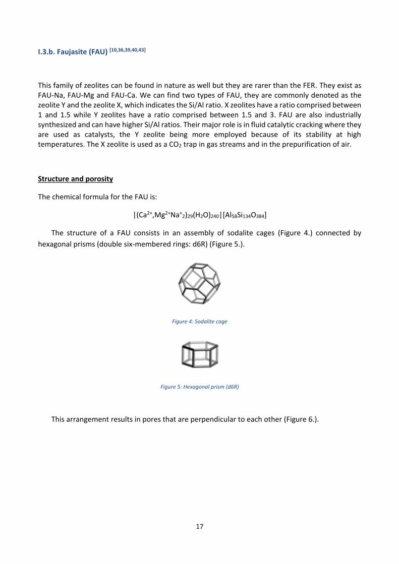
The structure of a FAU consists in an assembly of sodalite cages (Figure 4.) connected by
hexagonal prisms (double six-membered rings: d6R) (Figure 5.).
Figure 4: Sodalite cage
Figure 5: Hexagonal prism (d6R)
This arrangement results in pores that are perpendicular to each other (Figure 6.).

18
Figure 6: Arrangement of sodalite cages and double six-membered rings
The entire cell is cubic and its symmetry is Fd3̅m (Figure 7.) and the cell parameter is: a=24.74Å.
Figure 7: FAU framework along the [111] axis
Pores, in which most of the cations are adsorbed, are 12-membered rings which dimensions are
7.4x7.4 Å2 (Figure 8.).
Figure 8: 12 tetrahedra ring of the FAU along the <111> axes

19
I.3.c. LINDE TYPE L (LTL) [10, 21,34]
LTL zeolites are synthetic and are known for their excellent catalytic properties. They are used as
ethylene adsorbent as well. Ethylene being involved in the control of the growth process in plant
aging. LTL can also be useful for gases adsorption.
Structure and porosity
The chemical formula for LTL zeolites is:
|K+6Na+
3(H2O)21|[Al9Si27O72]
LTL zeolites are constituted of cancrinite cages (Figure 9.) connected to d6R.
Figure 9: Cancrinite cage
This ”pipe-like” pattern is linked to bigger cages called ltl (Figure 10.) resulting in the structure
shown in the Figure 11.
Figure 10: Ltl cage

20
Figure 11: LTL framework viewed along [100]
Ltl cages stackings form 12 tetrahedra rings channels which dimensions are 7.1x7.1 Å2 (Figure
12.). The cell is hexagonal with a P6/mmm symmetry and the cell parameters are: a=18.40Å and
c=7.52Å.
Figure 12: 12 tetrahedra ring of the LTL along [001]
I.4. Rare Earth Elements (REEs)
The rare earths are a family of elements comprising all the lanthanides (atomic number Z, comprised
between 57 and 71), the yttrium (Y, Z=39) and the scandium (Sc, Z=21). This name originates from
the early Greeks who called “Earth”, a material that could not be changed further by sources of
heat, and “Rare”, an element that is difficult to obtain pure [11]. REEs are indeed complicated to get
as pure metals because of their reactivity [12].
Those elements represent a hundredth of one percent of the mass of all elements present in
the Earth’s crust and they underwent intense physical and geological processes such as melting,
resolidification, mountain formation, erosion… Due to their similar physical and chemical
properties, their separation onto elemental mineral was not possible [11]. They are always found

21
together in nature because they all have an oxidation state of 3+, except for cerium (4+) and
europium (2+) [11,12]. Also, their ionic radii are almost the same, allowing isomorphous substitution
into various crystal lattices [12].
The REEs can be classified into two groups, the light rare earth elements (LREEs) and the heavy
rare earth elements (HREE) [11, 12]. The elements contained into those groups can vary from a book
to another but according to the REE handbook, we found the lanthanum (La), the cerium (Ce), the
praseodymium (Pr), the neodymium (Nd), the promethium (Pm), the samarium (Sm), the europium
(Eu) and the gadolinium (Gd) in the LREE and the terbium (Tb), the dysprosium (Dy), the holmium
(Ho), the erbium (Er), the thulium (Tm), the ytterbium (Yb), the lutetium (Lu) and the yttrium (Y) in
the HREE[13]. According to another source, the HREE would contain elements from Gd to Lu excluding
Yb but including Y and Sc. The LREE would be composed of the elements from La to Sm but excluding
Ce and Eu. Within each of those groups, the elements have similar chemical properties and thus are
almost always found together in mineral deposits [11]. A few chemical and physical differences exist
between them and they are caused by the small variation of their ionic radius, segregating them
into deposits enriched in either light or heavy REEs [12].
The most abundant REE is Ce but all of them are more common than silver (Ag) or mercury (Hg) [12]. Pm exists in very few quantities in natural materials and its most stable isotope is radioactive
with a half-life of 18 years [11, 12]. This element has properties that Nd and Sm do not have [11].
Generally, lanthanides having a low atomic number are more abundant than the others and those
with an even atomic number are two to seven times more common than those have an odd atomic
number [12].
I.4.a. Short historical overview [12]
Because of the similar chemical and physical properties of REEs, their isolation was complicated.
Efficient separation methods were developed during the twentieth century allowing the
identification of all the REE.
Those elements originate from small granitic pegmatite (magmatic rock) from which they were
first extracted. But from the second half of the nineteenth century to the first half of the twentieth
century, they were mainly coming from placer deposits from southeastern US. Later, heavy mineral
sands were used as source of REE by products. Those sands came from placer from many parts of
the world.
It is only in the fifty past few years that REE commercial markets started to develop, the REE
being commercially available since 1940’s with the exception of La, Ce and Nd. Those element have
been the most abundant and were commercialized earlier. Since 1998, China has been the first
provider of REE raw material with more than 80% of the global exploitation.

22
I.4.b. REEs Geological Insight [12,14]
Many minerals contains REEs but only less than ten are used for the worldwide production. Among
those we can find Cerianite [(Ce,Th)O2], Bastnasite (RECO3F) or Monazite [(RE,Th)PO4], with RE
corresponding to rare earth. One of the most important sources that is exploited by China is Laterite,
in which REEs are adsorbed into clay minerals and are easily extracted by ion exchange.
The main sources of REEs are as following:
- Iron-REE deposits: the largest REE resource in the world and they provide REE ion
ores, REE ores in silicalite rocks and REE ores in Dolomite.
- Carbonatite deposits: really abundant but only one site in California exploited them.
- Lateritic deposits: large resource that can present high REE contents. Poor in Ce
but rich in Y and La. They can ben locally enriched in HREE.
China exploited 2 sites.
- Placer deposits: more than 360 exist. The more commercial ones are in sands
from marine origin especially in India.
- HREE deposits in Peralkaline Igneous Rocks: enriched in HREE and Zirconium, only
one site mined in Russia.
- Vein deposits: low abundance in comparison with the hard rock deposits. Two
vein deposits were exploited in Africa in the past and more
recently two are mined in China.
- Other deposits: REE can accumulate in some places that do not correspond to
any of the categories mentioned before.
I.4.c. Properties [11]
The similarities observed in REEs chemical properties resulting from their atomic structure:
Electronic configuration
It has a huge influence on the crystal structures and thus on their surface structures. What needs to
be considered is the filling of the external electron subshell. From Pr to Sm and from Tb to Tm the
external electronic configuration changes between the atomic and the solid states. The divalent
4fn+1 6s2 atomic configuration becomes trivalent for the solid state, 4fn+1 (5d6s)3 with n=2-5 for Pr to

23
Sm and 8-12 for Tb to Tm. For La, Eu, Gd, Yb and Lu, the valency remains the same between both
states. The case of Ce is particular, its valency cannot be determined uniquely because of the 4f
occupancy.
Crystal structure
All the HREE, from Gd to Lu including Y and Sc but excluding Yb, adopt a hexagonal close packed
(hcp) structure. For Ce and Yb, their lattice is face centered cubic (fcc). Eu lattice has a base centered
cubic (bcc) lattice and all the others adopt a double c-axis hexagonal close packed (dhcp) structure,
except Sm that has a rhombic (rhom) lattice. We can notice that all the crystal structures are close
packed, except bcc, giving those elements a coordination number that is the highest (12). Figure 13
shows the crystal structures based on the hexagonal lattice.
Figure 13: Unit cells for the crystal structures based on the hexagonal lattice
We can notice a systematic variation of the room temperature close packed crystal structures
along the Lanthanide period. The fcc lattice is gradually evolving to the hcp structure (Table 1.).
Table 1
Lanthanides La-Ce La-Pm Sm Gd-Lu
fcc : hcp ratio 1:0 1/2:1/2 1/3:2/3 0:1
Crystal structure fcc dhcp rhom hcp

24
Ce and La were included in both fcc and dhcp because they undergo a fcc-dhcp transformation
close to the room temperature. If a high pressure is applied, those structures adopt the previous
one in the series. Gd and Tb revert to the Sm-type structure, Sm transforms into dhcp and La, Pr and
Nd adopt the fcc structure. Those transformations are due to the electronic structure of the rare
earths (RE) metals, the f occupancy changing across the series.
Electronic Structure
The lanthanides electronic structures can be compared to the transition metals electronic structure
in a way that they are filling an electronic shell across the series. The transition metals filling the 3d,
4d or 5d shell and the lanthanides filling the 4f shell.
The main difference that exists between those two series is that the 4f electrons of the
lanthanides behave very differently from the s, p and d valence electrons of any other atoms. 4f
electrons have a character that is close to core electrons but their valency cannot be omitted
because they still interact with other valence electrons.
I.4.d. Applications
REE have found uses in many domains which the most important are reported in Table 2.
Table 2 [14]
Application Percent of World REE Consumption
Permanent magnets 20
Optical materials polishing powder 16
Fluid petroleum cracking catalysts 12
Automobile gaseous pollution abatement catalysts
7
Rechargeable battery electrodes 10
Metallurgy, for example. Rare Earth Magnesium alloys
9
Phosphors 8
Glass additives 6
Ceramics 5
Others 7
As oxides, REEs are used in petroleum refining as compounds enriched in La and mixed REEs in
fluids cracking catalysts (FCC) [11,12,40,42]. They can be found in the catalysis of organic reactions such
as hydrogenation or in the formation of polyesters [11,58-61]. In the automotive industry [38], they are
used as exhaust pollution abatement catalysts [12, 14]. They found uses in phosphors present in
televisions and computers screens but also in fluorescent lightings [61-65]. Eu and Y oxides were

25
associated to give a brilliant red phosphor at the beginning of the 60’s and later Gd and Tb oxides
were combined to obtain green phosphors [11,12]. In the glass industry, Ce oxides are used as
polishers [11, 12]. When glasses are doped with REE oxides, their absorption characteristics are
modified allowing the development of specific, reproducible wavelength lasers output light [11,14].
Those lasers are used as high power lasers for cutting or welding, in solid state microwave devices
as radars and in electronic and optical devices [11,66-69]. REE oxides are also present in ceramics [70-72].
As metals, they are used in alloys to improve their strength, malleability, corrosion and oxidation
resistance and their creep resistance [11]. We can find them with iron (Fe), in steel and with transition
metals such as nickel (Ni), cobalt (Co) or manganese (Mn) for example [11,12]. They give Magnesium
(Mg) a higher temperature strength and a lower flammability; Pr is present in Mg alloys in exhaust
sections of jet engines, as well as Y, also present in coatings [11,12,14]. REE metals can be combined
with Hydrogen in rechargeable batteries or in refrigeration systems [12,14,76-79]. Alloys of Ce and Iron
(Fe) emit sparks when struck [11]. They are used in permanent magnets present in many
electrochemical devices such as ultra-light weight headphones and light weight electric motors, the
world strongest permanent magnet being a combination of REE, Co and Fe [11, 12, 14,73-75].
Isotopes of REEs also have applications. Irradiated Tm produces X-Rays which are used in
portable units for medics or archeologist investigating metallic artefacts [11]. Y is used for cancer
therapy [80-83] and relative abundance of Lu isotopes are used to date meteorites [11].
II. Instruments and analytical methods
II.1. Characterization methods used on zeolites
II.1.a. Energy Dispersive X-ray Spectrometry (EDX)
The chemical composition of the zeolites was determined using an Oxford INCA 350 EDX
microanalysis system. It was associated to a Hitachi S-4800 FE-Scanning Electron Microscope (SEM).
Principles of the technique [19]
This technique analyses the X-rays emitted by a solid sample when bombarded with a focused beam
of electrons. It provides information about the local chemical composition of the sample. Those
devices are supposed to be able to detect elements which atomic number (Z) goes from 4 (Beryllium,
Be) to 92 (Uranium, U) but not all of them are equipped for low Z elements (Z<10).

26
X-ray patterns obtained are very simple and allow a direct qualitative analysis by line
identification. The intensities of the lines can be measured for each element present in the samples.
Thus, quantitative analyses can be performed giving the concentration of the elements that are
present.
The emitted X-rays can be scanned and their intensities displayed. Then, element distribution
images can be obtained. Those elemental maps produced by electrons can show surface topography
or mean number differences according to the mode selected.
EDX devices are often associated to SEM that are designed to provide electron images or
element maps. When connected to an X-ray spectrometer, point analyses are allowed. The
functions of both of these devices considerably overlap.
II.1.b. X-Ray Diffraction (XRD) [20]
The patterns corresponding to the zeolites structures were collected with XRD Philips PW3710
PW3020, X-ray powder diffractometer.
XRD is one of the most powerful characterization method for quantitative and qualitative
analyses of crystalline materials. Many information can be provided with this technique, including
the number, the types and the nature of the phases that are present, but also the amount of
amorphous content and the orientation of the crystallites.
Principles of the technique
Atoms from a crystalline structure are arranged in a regular pattern. X-rays are emitted onto a
sample and interact with the atoms which neighbor electrons will start to oscillate at the same
frequency than the incident rays. This phenomenon generates constructive and destructive
interferences, and diffracted rays as well. Destructive interferences, a combination of out of phase
waves, are emitted in almost all the directions. To obtain constructive interferences, the production
of in phase waves is necessary and has to fulfil the Bragg’s law:
𝑛𝜆 = 2𝑑 sin Θ (LI)
being the wavelength of the electromagnetic radiation, Θ, the angle of the incident ray and d,
the lattice spacing in the crystalline sample. The diffracted X-rays are then detected, processed and
counted.

27
II.1.c. Attenuated Total Reflectance – Fourier Transform InfraRed spectroscopy (ATR-
FTIR)
The infrared spectra of the zeolites were recorded using a Perkin Elmer Spectrum One FTIR
spectrometer associated with a Universal sampling accessory.
ATR-FTIR is a technique that allows the collection of IR spectra in a very simple way. It does not need
any particular sample preparation such as KBr pellets and permits the analysis of a wide range of
samples.
Principles of the technique [22]
The samples are deposited on the ATR crystal, consisting in a trapezoid IR transparent material
having a high refractive index polished surfaces. The IR beam strikes the ATR crystal with an angle
of 45° relative to the crystal surface. The interface between the crystal and the sample (longest
surface of the trapezoid) will reflect totally the beam which will be totally reflected again on the
opposite surface of the crystal. The beam will be reflected this way several times until it gets out of
the crystal and reaches the detector.
To record a high quality spectrum a good contact between the sample and the crystal and the
refractive index of the crystal has to be much higher than the sample’s one.
II.2. Elemental analysis: Microwave Plasma – Atomic Emission Spectroscopy
(MP-AES)
For the detection of the REEs an Agilent 4100 MP-AES was used.
Principles of the method [23, 24]
Nitrogen is excited by microwaves to obtain plasma. The sample is nebulized and passes through
the plasma. Thus, electrons are transferred to the excited state. When they return to the ground
state, they emit light which intensity is measured by the detector.

28
III. Materials and methods
The goal of the current study is to understand basically how the ion exchange behavior of
lanthanides would be affected by zeolites with varied framework structures and charge densities.
Three framework types (FER, LTL and FAU) were chosen. Also, within the FAU structure, three
different Si/Al ratios were selected (Y330, Y350 and Y360). All the selected zeolites are commercially
available and can be produced in mass quantity. Lanthanum serves as our primary investigating
element and the ion exchange behavior of La onto those zeolites was studied. Another possible
objective of the work was to find out if the zeolites would be useful for REEs separation. The ternary
system comprising La, Nd and Dy was also studied.
III.1. Sodium ion exchange of the zeolites
The raw zeolites that were used, presented a random distribution of protons as charge
compensating ions in their framework. In order to start our study with equivalent conditions for all
the zeolites and to achieve comparable results, it was necessary to process to an ion exchange to
obtain the zeolites under pure sodium form.
Five grams of each zeolites were weighted and placed respectively into 100mL polypropylene
bottles. A solution of 0.1 M sodium nitrate (NaNO3) was prepared with a sufficient volume to fill the
bottles. The mixtures were left to stir for two days on a rotary mixer (50 rpm) and the NaNO3 solution
was pipetted out after centrifugation. This step was repeated three times. The zeolites were placed
in an oven at 70°C for two days.
III.2. Batch wise ion exchange with Lanthanum [37]
This part of the work was focused on the study of the lanthanum behavior inside the zeolites, first
with the analyses of the uptakes at different equilibrium pH values, the concentration of lanthanum
in the initial solution remaining constant. Second with the observation of Lanthanum uptakes having
different concentrations but with constant pH values, in order to obtain isotherms.
III.2.a. pH uptake behaviors
Those tests were performed with a lanthanum concentration of 1 mM. For this, lanthanum nitrate
(La(NO3)3.6H2O) was used. 0.1 M NaNO3 solution was used as background and the pH was preset
with concentrated nitric acid (69% HNO3). To adjust the pH to the desired values, sodium hydroxide

29
(NaOH) solutions were used. To each 20 mL sample vial, 0.1g of dried Na exchanged zeolites were
weighted and placed. The test solutions were then introduced into the vial and left to stir for 2 days.
The initial solution pH were controlled at the range of 2 to 5. After two days of stirring, pH of
the solutions was measured and it was noticed that it was higher than the initial values. It was
thought that protons from HNO3 replaced sodium inside the zeolites or that NaOH was released into
the supernatant by hydrolysis. The solution pH was again adjusted by drops of HNO3 or NaOH to
achieve the equilibrium pH range from 1 to 5.
In total, nine samples were prepared (solution + zeolite) with their corresponding references
(solution only).
After the two days stirring, part of the supernatant was pipetted out from the samples and the
references, and was mixed with deionized water, cesium (Cs) and HNO3 for elemental analyses with
Microwave Plasma – Atomic Emission Spectrometry (MP-AES). Cs serves as the ionization
suppressor and HNO3 provides a constant acid background. The whole samples and standards
preparations are presented in appendix 1.
III.2.b. Isotherm study
For this part, the lanthanum uptakes behavior was observed at different concentrations but at a
constant value of equilibrated pH. With the results obtained from the previous step, it was
determined that one of the relevant pH values was pH 3. Different concentration domains were
tested before defining that the one of interest was from 0 to 10 mM of La.
Two solutions were prepared. The first one with La(NO3)3.6H2O, HNO3 (69%), and the
background of 0.1 M NaNO3, to obtain a 10 mM solution of La at an equilibrated pH value of 3 once
mixed with the zeolites. The second one was prepared as a dilution solution to reach the desired
concentration values. Therefore, HNO3 was used to set the pH value at the same pH than the
previous solution and 0.1 M NaNO3 solution was used for dilution.
Again, nine samples were prepared with 0.1 g of Na exchanged zeolite and placed into 20mL
vials and the corresponding references were also collected. The samples with the zeolites were left
to stir for two days. The same procedure was used to prepare the MP-AES samples.
III.3. Ion exchange study of an equimolar solution of lanthanum, neodymium and
dysprosium
In this part, the behavior of the equimolar ternary system of La, Nd and Dy was studied. This was
made in order know if the zeolites were selective toward REEs. Firstly, pH-capacity tests were carried

30
out. Uptakes of those elements were analyzed at different pH values in zeolites. Secondly, elution
of the zeolites was performed.
III.3.a. pH-capacity study
A 1 mM equimolar solution of La, Nd and Dy was prepared. For this, La(NO3)3.6H2O, Nd(NO3)3.6H2O
and Dy(NO3)3.6H2O were used in addition of concentrated HNO3 (69%), 0.1 M NaNO3 as background
and deionized water. In the same way than before, HNO3 was used to preset the pH and NaOH to
adjust the values. To each sample vial, 0.1g of dried Na exchanged zeolites were weighted and mixed
with the solution at the different pH values. The solutions were left to stir for 2 days and pH was
adjusted also by drops of HNO3 or NaOH to achieve the equilibrated pH domain from 1 to 5. Nine
samples were prepared with their corresponding references.
Once more, part of the supernatant was pipetted out from the samples and the references, and
was diluted and mixed with cesium (Cs) and HNO3 for MP-AES analyses.
III.3.b. Elution of the zeolites
The supernatant of the samples from the previous pH tests were pipetted out and the zeolites
surface were briefly cleaned three times with 20 mL of 0.1 M NaNO3 to remove any residual REEs.
An acid solution was prepared at a pH of 1.51 with the use of HNO3 and was mixed with the zeolites.
The solution was left to stir for two days and then, the supernatant was pipetted out for MP-AES
sample preparation and analyses.
IV. Results and discussion
IV.1. Characterization of the raw zeolites
For the characterization of our samples Scanning Electron Microscopy – Energy Dispersive X-ray
spectroscopy (SEM-EDX), X-Ray Diffraction (XRD) and Attenuated Total Reflectance – Fourier
Transform InfraRed spectroscopy (ATR-FTIR) were used.

31
IV.1.a. SEM/EDX
EDX gave the atomic percentages (%at) of Si and Al allowing the calculation of Si/Al ratios of our raw
zeolites. They were then classified into groups (high/intermediate/low silica) approved by the
International Zeolites Association Structure Commission (IZA-SC). (Table 3.).
Table 3
Zeolites %at Si %at Al Si/Al IZASC group
LTL 12.3 4.1 3.0 Intermediate silica
FER 21.7 3.1 7.0 High silica
Y360 13.4 1.5 8.7 High silica
Y350 13.8 2.8 4.9 Intermediate silica
Y330 15.6 5.2 3.0 Intermediate silica
EDX being associated with SEM, images of the zeolites were collected and appear in appendix 2.
IV.1.b. XRD patterns compared with reference patterns
XRD patterns were collected to confirm the structures of our zeolites. The reference patterns were
taken from the IZA-SC web site. Figures 14 to 16 show the collected and the reference patterns of
the raw zeolites.
Figure 14: XRD patterns corresponding to LTL zeolite
0
50
100
150
200
250
300
0 5 10 15 20 25 30 35 40 45 50 55 60 65 70 75
Inte
nsi
ty
2Θ
LTL LTL ref

32
Figure 15: XRD patterns corresponding to FER zeolite
Figure 16: XRD patterns corresponding to FAU zeolites
On each pattern it is observed that the peaks from the references and from the samples
correspond to each other. The selected zeolite structure is then confirmed.
0
50
100
150
200
250
300
350
400
0 5 10 15 20 25 30 35 40 45 50 55 60 65 70 75
Inte
nsi
ty
2Θ
FER FER ref
-100
100
300
500
700
900
1100
1300
0 10 20 30 40 50 60 70
Inte
nsi
ty
2Θ
Y360 Y350 Y330 Y reference

33
IV.1.c. IR spectra before and after Na ion exchange [16,17,29,33]
On IR spectra, vibrations of the zeolites framework can be observed. They are distributed as shown
on Figure 17.
Figure 17: Principal bands observed from zeolites framework.
The solid line represents the intratetrahedral vibrations (within tetrahedra) and the broken line
represent intertetrahedral vibrations (between adjacent tetrahedra).
Cations vibrations can also be observed in the far infrared (200-50 cm-1) because they undergo
frustrated translational motion with respect to the lattice. Those vibrations will not be observed on
the collected IR spectra because the device was not powerful enough to reach the far-IR domain.

34
Figure 18: ATR-FTIR spectra of the LTL zeolite.
Figure 19: ATR-FTIR spectra of FER zeolite
55
60
65
70
75
80
85
90
95
100
5001000150020002500300035004000
Ref
lect
ance
%
Wavenumber cm-1
LTL before exchange LTL after exchange
75
80
85
90
95
100
5001000150020002500300035004000
Ref
lect
ance
%
Wavenumber cm-1
FER before exchange 2 FER after exchange
35
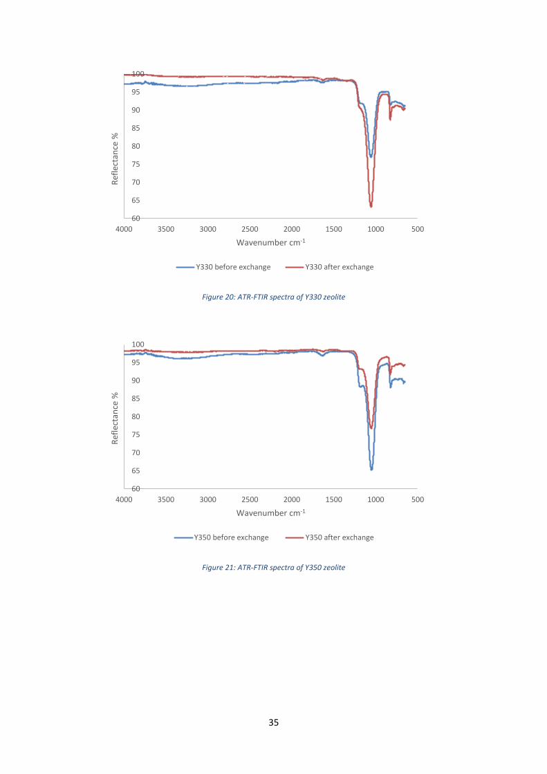
Figure 20: ATR-FTIR spectra of Y330 zeolite
Figure 21: ATR-FTIR spectra of Y350 zeolite
60
65
70
75
80
85
90
95
100
5001000150020002500300035004000
Ref
lect
ance
%
Wavenumber cm-1
Y330 before exchange Y330 after exchange
60
65
70
75
80
85
90
95
100
5001000150020002500300035004000
Ref
lect
ance
%
Wavenumber cm-1
Y350 before exchange Y350 after exchange
36
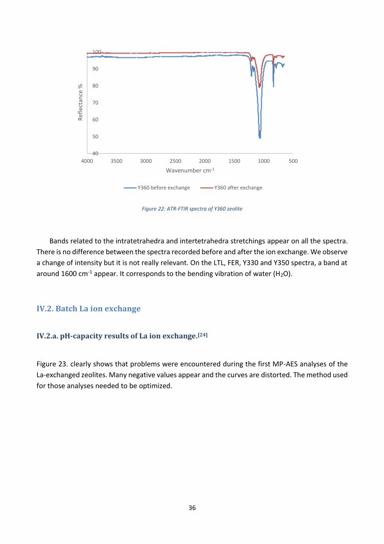
Figure 22: ATR-FTIR spectra of Y360 zeolite
Bands related to the intratetrahedra and intertetrahedra stretchings appear on all the spectra.
There is no difference between the spectra recorded before and after the ion exchange. We observe
a change of intensity but it is not really relevant. On the LTL, FER, Y330 and Y350 spectra, a band at
around 1600 cm-1 appear. It corresponds to the bending vibration of water (H2O).
IV.2. Batch La ion exchange
IV.2.a. pH-capacity results of La ion exchange.[24]
Figure 23. clearly shows that problems were encountered during the first MP-AES analyses of the
La-exchanged zeolites. Many negative values appear and the curves are distorted. The method used
for those analyses needed to be optimized.
40
50
60
70
80
90
100
5001000150020002500300035004000
Ref
lect
ance
%
Wavenumber cm-1
Y360 before exchange Y360 after exchange

37
Figure 23: pH vs Capacity of La ion exchange before optimization
The troubles encountered during our analyses were due to the low plasma capacity of nitrogen
plasma compared with argon plasma. The salt concentration in the sample essentially affects the
atomization rate of other co-existing ions. The analysis of this kind of high matrix samples in MP-
AES deserves careful attention.
As a first attempt, we thought that sodium might be building up in the torch, leading to lower
and lower atomization rate. Hence, the system rinsing time between each sample was increased.
This kind of modification can be useful when salts are formed on the sample introduction or on the
torch. Sample contamination can also be avoided [18]. But increasing the rinsing time of the method
unfortunately did not improve the results.
The second attempt was to lower the amount of solution in the plasma by reducing the
nebulizer pressure [18]. Again the results remained almost the same. This indicated that our salt
concentration was still over the plasma capacity even though with minimum amount of analyte.
Matrix matching was finally carried out. 0.1M NaNO3 solution was added to the standard
solutions, in the same proportions than in the La exchanged zeolite samples, in order to decrease
the influence of Na emission line on the signal. The curves on Figure 24. were obtained.
-0,06
-0,04
-0,02
0
0,02
0,04
0,06
0,08
0 1 2 3 4 5 6 7
Cap
acit
y m
mo
l/g
pH
LTL Capacity FER Capacity Y330 Capacity
Y350 Capacity Y360 Capacity

38
Figure 24: pH vs Capacity of La ion exchange after optimization
A satisfying curve was obtained for the LTL zeolite reaching a maximum capacity of 0.16 mmol/g
and starting to flatten at pH 3. The other curves show that the corresponding zeolites present too
low capacity toward La and therefore, the REEs. FER and FAU zeolites were then rejected and only
LTL was kept for the rest of the study. The capacity calculations appear on appendix 3.
IV.2.b. Analysis of Al content after La ion exchange.
With MP-AES, the concentration in Al in the supernatant was also analyzed. Figure 25. shows that
at low pH values, a high concentration of Al is released in the supernatant of the La exchanged LTL.
It was thought that it was charge compensating Al released in solution or Al from the framework
implying possibly, the destruction of the zeolite structure.
-0,04
-0,02
0
0,02
0,04
0,06
0,08
0,1
0,12
0,14
0,16
0,18
0 1 2 3 4 5 6 7
Cap
acit
y m
mo
l/g
pH
Capacity LTL Capacity FER Capacity Y330
Capacity Y350 Capacity Y360

39
Figure 25: Evolution of Al concentration with pH after La ion exchange
With the EDX analysis results of the raw zeolites, the weight percentages of Al were calculated
and was found to be 5% for LTL. Thus, the percentage of Al dissolved in the supernatant could be
calculated. Its evolution is obviously the same than in the previous graph (Figure 26.). The detailed
calculation appears in appendix 3. It is worth mentioning that during the initial sodium exchange
processes, the charge compensating Al ions cannot be effectively eliminated due to their high
charges compared with sodium. The zeolitic framework prefers higher charge ions rather than
sodium with only one positive charge. During the La ion exchange, La ion has the same amount of
charge than Al, therefore some of the Al in exchangeable ion position was washed out, especially in
lower pH were hydronium concentration is much higher.
0
2
4
6
8
10
12
14
16
18
0 1 2 3 4 5
Al c
on
cen
trat
ion
(m
M)
pH

40
Figure 26: Evolution of Al% with pH after La ion exchange
IV.2.c. La ion exchange isotherm [28,36,41,45]
On Figure 24., the flattening of the curve is observed to start at pH 3, the constant pH value chosen
for the isotherm.
The isotherm obtained for La exchanged LTL appears on Figure 27.
Figure 27: Isotherm obtained after La ion exchange
0
0,2
0,4
0,6
0,8
1
1,2
1,4
1,6
1,8
2
0 1 2 3 4 5
%A
l dis
solv
ed i
n t
he
sup
ern
atan
t
pH
0
0,05
0,1
0,15
0,2
0,25
0,3
0,35
0,4
0 2 4 6 8 10
Cap
acit
y (m
mo
l/g)
Concentration (mM)

41
It can be noticed that this isotherms follows Langmuir’s model meaning that the ion exchange
is a chemisorption process. The curve reaches a maximum capacity of 0.25 mmol/g.
IV.3. XRD characterization of the La exchanged LTL
The pattern on Figure 28. shows that the structure of the zeolite is not affected by the pH variation
during the La exchange, when the pH is above 2.27. The Al contained in the supernatant solution at
a pH above 2.27 does not come from the framework but was present as a charge compensating
cation.
Figure 28: XRD patterns of La exchanged LTL at different pH values
Figure 29. shows the XRD pattern of the La exchanged LTL after the variation of the La
concentration. Again, structure remains the same implying that the concentration of La do not affect
the framework of the zeolite.
0
100
200
300
400
500
600
0 10 20 30 40 50 60 70
Inte
nsi
ty
2Θ
LTL pH 4.091 LTL pH 3.045 LTL pH 2.27 LTL raw zeolite

42
Figure 29: XRD patterns of La exchanged LTL at different pH values
IV.4. Batch La-Nd-Dy ion exchange
IV.4.a. pH-capacity results of La-Nd-Dy ion exchange
It is observed that the capacity decreases when the atomic number of the REEs increases making it
more selective toward low atomic number REEs.
Figure 30: pH vs Capacity for La-Nd-Dy ion exchange
0
100
200
300
400
500
600
0 10 20 30 40 50 60 70
Inte
nsi
ty
2Θ
LTL 5mM LTL 2mM LTL 1mM LTL 0,25 mM LTL raw zeolite
0
0,02
0,04
0,06
0,08
0,1
0,12
0,5 1,5 2,5 3,5 4,5
Cap
acit
y m
mo
l/g
pH
Capacity of La3+in LTL (394.910nm) Capacity LTL Dy3+(353.171nm)
Capacity LTL Nd3+(415.608 nm)

43
For La, the capacity reaches a maximum value of approximately 0.11 mmol/g. It decreases to a
value of around 0.09 mmol/g for Nd. For Dy, it reaches ca. 0.04 mmol/g. The curves all start to
flatten at around pH 3.
IV.4.b. Elution result
At pH 1.51, set with HNO3, all the elements contained in LTL were washed out making the ion
exchange of REEs a process easily reversible.
Figure 31: pH vs Concentration of REEs after elution
IV.4.c. Analysis of Al content after La-Nd-Dy ion exchange.
At low pH values, the supernatant does not contain Al. Before the elution, pH tests were carried out
on the zeolite. At low pH values, it was observed on Figure 25., that a high concentration of Al,
corresponding to extra framework Al, was released into the supernatant. All the charge
compensating Al was then already washed out before the elution.
The acidification of the solution due to elution just washed out the Al that was present before,
for the pH tests at high pH values.
0
0,05
0,1
0,15
0,2
0,25
0,3
0,35
0 1 2 3 4 5 6
mM
pH
[La3+] in the supernatant after elution [Dy3+] in the supernatant after elution
[Nd3+] in the supernatant after elution

44
Figure 32: Evolution of Al concentration with pH after elution.
V. Conclusions and outlooks
The characterization of our commercially available FER, LTL and FAU with the use of XRD allowed
the confirmation of their framework structure and their composition, by comparison with reference
patterns provided by the IZA-SC. With EDX, atomic and weight percentages of the structure were
obtained and the zeolites were classified into groups approved by the IZA-SC. ATR-FTIR showed us
the intra- and intertetrahedral stretchings in the framework.
Some troubles were encountered with the use of MP-AES but solutions were found and reliable
results were finally obtained. Among the five selected zeolites, it was determined that only LTL was
potentially useful for the REEs ion exchange. Indeed, this zeolite was showing a satisfying capacity
value of approximately 0.16 mmol/g while the others had too low capacity for REEs uptakes. The
pH-uptake curve of LTL was observed to start to flatten at around pH 3.
It was shown that after La ion exchange, at low pH values, a substantial amount of Al was
released in solution. With EDX, the Al weight percentage of the LTL zeolite was obtained and was
found to be about 5.4%. The highest quantity of Al that was released in solution was 1.8% at pH 1.3.
The XRD patterns corresponding to the La exchanged LTL after pH variation showed that the
structure of the zeolite was not affected by the pH when above the value of 2.27, implying that the
Al released in the solution might not be coming from the framework.
The results obtained from the MP-AES also allowed the plotting of the isotherm, corresponding
to a concentration range from 0.01 mmol to 10 mmol of La at pH 3. It was observed that the curve
-1
0
1
2
3
4
5
6
7
8
0 1 2 3 4 5 6
mM
pH

45
reached a maximum capacity value of about 0.25 mmol/g. The shape of the curve was following
Langmuir’s model implying a chemisorption ion exchange process. The XRD patterns recorded for
different concentrations of La from the isotherm experiment shows that the structure of the LTL
zeolite remains unchanged with the variation of La concentration.
With the MP-AES results from the pH-capacity experiment on the ternary equimolar mixture of
La-Nd-Dy, it was observed that the maximum capacity of La was about 0.11 mmol/g. For Nd, the
maximum capacity was approximately 0.09 mmol/g and for Dy it was around 0.04 mmol/g. The
capacity of the LTL zeolite is thus decreasing with the increasing atomic number of the REEs. The
elution of the zeolite allowed all the REEs to be washed out with the simple use of nitric acid, used
to set the elution solution at pH 1.51. This ion exchange process is thus easily reversible.
Finally, the LTL zeolite could find potential uses in REEs separation. It has considerable capacity
towards those elements and even favors uptakes of REEs having a low atomic number. Thus, it could
be interesting to carry out those experiments on other zeolites, having the same kind of framework
or presenting similar characteristics, such as Linde Type A (LTA) or Linde Type N (LTN) zeolites, to
observe if the behavior of REEs ion exchange remains the same or not. In order to confirm this
affinity between LTL and low atomic number REEs, other REEs should be tested. Studying this
phenomenon in zeolites presenting a completely different structure than FAU and FER could also be
relevant. In addition, due to the low capacity of Y zeolite studied here, the effects of the framework
charge density on REEs uptake behavior still remains unclear. Further efforts are in need with this
regard.
The characterization of the REE exchanged zeolites could also be beneficial to deepen our
understanding towards the behavior. The use of a far-IR spectroscopy device could be useful to be
able to observe the vibrations due to the cation motions in the framework. X-ray photoelectron
spectroscopy might be another choice.
Overall, the current study initiated the investigation of zeolite ion exchange behavior towards
REEs, especially lanthanides, whose chemical characteristics are very much similar. The separation
of REEs till today is still challenging. The fundamental understanding of their ion exchange behavior
in ordered structure aluminosilicates could give rise to a more rational design in the separation
processes.

46
VI. References
[1] HUREAU, Matthieu. Séparation de charges de molécules linéaires insérées dans des zéolithes à
canaux. 2007. Thèse de doctorat. Université des Sciences et Technologie de Lille-Lille I.
[2] LUCHEZ, Florence. Séparation de charges de molécules aromatiques insérées dans des zéolithes
à canaux: application à la formation de clusters d'argent intrazéolithique. 2010. Thèse de doctorat.
Université Lille 1-Sciences et Technologies.
[3] MITTAL, Vikas (ed.). Encapsulation nanotechnologies. John Wiley & Sons, 2013.
[4] INGLEZAKIS, Vassilis J. The concept of “capacity” in zeolite ion-exchange systems. Journal of
Colloid and Interface Science, 2005, vol. 281, no 1, p. 68-79.
[5] HARJULA, Risto, DYER, Alan, PEARSON, Sarah D., et al. Ion exchange in zeolites. Part 1.—
Prediction of Ca2+–Na+ equilibria in zeolites X and Y. J. Chem. Soc., Faraday Trans., 1992, vol. 88, no
11, p. 1591-1597.
[6] AC03480727, Anonymus (ed.). Application of ion exchange processes for the treatment of
radioactive waste and management of spent ion exchangers. Internat. Atomic Energy Agency, 2002.
[7] FRUIJTIER-PÖLLOTH, Claudia. The safety of synthetic zeolites used in detergents. Archives of
toxicology, 2009, vol. 83, no 1, p. 23-35.
[8] BARLOKOVA, D. NATURAL ZEOLITES IN THE WATER TREATMENT PROCESS. Slovak Journal of Civil
Engineering, 2008, vol. 16, no 2, p. 8-12.
[9] HARJULA, Risto. Ion exchange and hydrolysis reactions in zeolites. 1993.
[10] BAERLOCHER, Ch, MCCUSKER, Lynne B., et OLSON, David H. Atlas of zeolite framework types.
Elsevier, 2007.
[11] BARRETT, Stephen David et DHESI, Sarnjeet S. The structure of rare-earth metal surfaces. World
Scientific, 2001.
[12] CASTOR, Stephen B. et HEDRICK, James B. Rare earth elements. Industrial minerals volume, 7th
edition: Society for mining, metallurgy, and exploration, Littleton, Colorado, 2006, p. 769-792.
[13] http://www.reehandbook.com/
[14] LUCAS, Jacques, LUCAS, Pierre, LE MERCIER, Thierry, et al. Rare Earths: Science, Technology,
Production and Use. Elsevier, 2014.
[15] LITO, Patrícia F., CARDOSO, Simão P., LOUREIRO, José M., et al. Ion exchange equilibria and
kinetics. In : Ion Exchange Technology I. Springer Netherlands, 2012. p. 51-120.

47
[16] KARGE, Hellmut G. et WEITKAMP, Jens (ed.). Characterization I. Springer Science & Business
Media, 1998
[17] http://www.iza-online.org/ (12/03/2016)
[18] https://www.agilent.com/cs/library/technicaloverviews/public/5991-3703EN.pdf
(28/04/2016)
[19] INGRAM, P., SHELBURNE, J. D., et LEFURGEY, A. Principles and instrumentation. Biomedical
applications of microprobe analysis. Academic Press, San Diego, CA, 1999, p. 1-58.
[20] SANGARAJU, Sandeep Kumar Raju. Metal induced crystallization of silicon thin films. 2009.
[21] JOSHI, P. N. et SHIRALKAR, V. P. Carbon dioxide sorption isotherms in LTL zeolites. The Journal
of Physical Chemistry, 1993, vol. 97, no 3, p. 619-624.
[22] KAZARIAN, S. G. et CHAN, K. L. A. Applications of ATR-FTIR spectroscopic imaging to biomedical
samples. Biochimica et Biophysica Acta (BBA)-Biomembranes, 2006, vol. 1758, no 7, p. 858-867.
[23] https://www.agilent.com/cs/library/slidepresentation/Public/GCC2011-
Wksp_MP%20Presentation.pdf (28/04/2016)
[24] Munthali, M. W., Kabwadza-Corner, P., Johan, E., & Matsue, N. (2014). Decrease in Cation
Exchange Capacity of Zeolites at Neutral pH: Examples and Proposals of a Determination Method.
Journal of Materials Science and Chemical Engineering, 2014.
[25] LEVEQUE, Alain et MAESTRO, Patrick. Terres rares. Ed. Techniques Ingénieur, 2005.
[26] Kuronen, M., Harjula, R., Jernström, J., Vestenius, M., & Lehto, J. (2000). Effect of the
framework charge density on zeolite ion exchange selectivities. Physical Chemistry Chemical
Physics, 2(11), 2655-2659.
[27] WILSON, Ian D., COOKE, Michael, et POOLE, Colin F. Encyclopedia of separation science.
2000.
[28] Majdan, M., Pikus, S., Kowalska-Ternes, M., Gładysz-Płaska, A., Staszczuk, P., Fuks, L., &
Skrzypek, H. (2003). Equilibrium study of selected divalent d-electron metals adsorption on A-type
zeolite. Journal of colloid and interface science, 262(2), 321-330.
[29] LI, Gonghu. FT-IR studies of zeolite materials: characterization and environmental
applications. 2005.
[30] KUMAR, Sanjeev et JAIN, Sapna. History, introduction, and kinetics of ion exchange materials.
Journal of Chemistry, 2013, vol. 2013.
[31] HELFFERICH, Friedrich et PLESSET, Milton S. Ion exchange kinetics. A nonlinear diffusion
problem. The journal of chemical physics, 1958, vol. 28, no 3, p. 418-424.

48
[32] ĆURKOVIĆ, Lidija, CERJAN-STEFANOVIĆ, Štefica, et FILIPAN, Tugomir. Metal ion exchange by
natural and modified zeolites. Water research, 1997, vol. 31, no 6, p. 1379-1382.
[33] LI, Can et WU, Zili. Microporous materials characterized by vibrational spectroscopies.
Handbook of Zeolite Science and Technology, CRC Press, Boca Raton, 2003, p. 423-514.
[34] INSUWAN, Wilaiporn et RANGSRIWATANANON, Kunwadee. Morphology-Controlled Synthesis
of Zeolite and Physicochemical Properties. Engineering Journal, 2012, vol. 16, no 3, p. 1-12.
[35] KABWADZA-CORNER, Ponyadira, JOHAN, Erni, et MATSUE, Naoto. pH Dependence of Lead
Adsorption on Zeolites. Journal of Environmental Protection, 2015, vol. 6, no 1, p. 45.
[36] REES, Lovat VC et ZUYI, Tao. Rare-earth ion exchange in zeolite Y. Zeolites, 1986, vol. 6, no 3,
p. 201-205.
[37] CARVAJAL, Ralf, CHU, Po-Jen, et LUNSFORD, Jack H. The role of polyvalent cations in
developing strong acidity: A study of lanthanum-exchanged zeolites. Journal of Catalysis, 1990, vol.
125, no 1, p. 123-131.
[38] GASSER, M. S. et ALY, M. I. Separation and recovery of rare earth elements from spent nickel–
metal-hydride batteries using synthetic adsorbent. International Journal of Mineral Processing,
2013, vol. 121, p. 31-38.
[39] SMITH, J. V. Structural classification of zeolites. Mineral Soc Am Spec Paper, 1963, vol. 1, p.
281-290.
[40] SOUSA-AGUIAR, Eduardo Falabella, TRIGUEIRO, Flávia Elias, et ZOTIN, Fatima Maria Zanon.
The role of rare earth elements in zeolites and cracking catalysts. Catalysis today, 2013, vol. 218, p.
115-122.
[41] QIN, Chenghuan, WANG, Ren, et MA, Wei. Characteristics of calcium adsorption by Ca-
Selectivity zeolite in fixed-pH and in a range of pH. Chemical Engineering Journal, 2010, vol. 156,
no 3, p. 540-545.
[42] WORMSBECHER, Rick, CHENG, W., et WALLENSTEIN, Dieter. Role of the Rare Earth Elements
in Fluid Catalytic Cracking. Retrieved February, 2010, vol. 16, p. 2015.
[43] SANCHEZ-CASTILLO, Marco A., MADON, Rostam J., et DUMESIC, James A. Role of rare earth
cations in Y zeolite for hydrocarbon cracking. The Journal of Physical Chemistry B, 2005, vol. 109,
no 6, p. 2164-2175.
[44] TOWNSEND, Rodney P. et COKER, Eric N. Ion exchange in zeolites. Studies in surface science
and catalysis, 2001, vol. 137, p. 467-524.
[45] SMIT, Berend et MAESEN, Theo LM. Molecular simulations of zeolites: adsorption, diffusion,
and shape selectivity. Chemical reviews, 2008, vol. 108, no 10, p. 4125-4184.

49
[46] VAUGHAN, Philip A. The crystal structure of the zeolite ferrierite. Acta Crystallographica,
1966, vol. 21, no 6, p. 983-990.
[47] Zhou, C., Yuan, C., Zhu, Y., Caro, J., & Huang, A. (2015). Facile synthesis of zeolite FAU
molecular sieve membranes on bio-adhesive polydopamine modified Al 2 O 3 tubes. Journal of
Membrane Science, 494, 174-181.
[48] Chakarova, K., Andonova, S., Dimitrov, L., & Hadjiivanov, K. (2016). FTIR study of CO and N 2
adsorption on [Ge] FAU zeolites in their Na-and H-forms. Microporous and Mesoporous Materials,
220, 188-197.
[49] GAONA-GÓMEZ, Adriana et CHENG, Chil-Hung. Modification of zeolite L (LTL) morphology
using diols,(OH) 2 (CH 2) 2 n+ 2 On (n= 0, 1, and 2). Microporous and Mesoporous Materials, 2012,
vol. 153, p. 227-235.
[50] ISOBE, Motohiro, MOTEKI, Takahiko, TANAHASHI, Shinya, et al. Plate-like precursors formed
in crystallization process of ferrierite from (Na, K)-aluminosilicate system. Microporous and
Mesoporous Materials, 2012, vol. 158, p. 204-208.
[51] THUADAIJ, P. et NUNTIYA, A. Preparation and characterization of faujasite using fly ash and
amorphous silica from rice husk ash. Procedia Engineering, 2012, vol. 32, p. 1026-1032.
[52] Liu, Y., Lu, J., Zhang, Y., & Wang, J. (2011). Synthesis and properties of Na-ferrierite tubular
membrane formed on macroporous α-Al 2 O 3 support by conventional and vacuum-assisted
secondary growth. Separation and purification technology, 81(1), 1-11.
[53] Dhainaut, J., Daou, T. J., Chappaz, A., Bats, N., Harbuzaru, B., Lapisardi, G., ... & Patarin, J.
(2013). Synthesis of FAU and EMT-type zeolites using structure-directing agents specifically
designed by molecular modelling. Microporous and Mesoporous Materials, 174, 117-125.
[54] KIM, Seok Han, KOMARNENI, Sridhar, et HEO, Nam Ho. ZSM-5 and ferrierite single crystals
with lower Si/Al ratios: Synthesis and single-crystal synchrotron X-ray diffraction studies.
Microporous and Mesoporous Materials, 2011, vol. 143, no 1, p. 243-248.
[55] Schäfer-Sindlinger, A., Pfeifer, M., Spurk, P., Demel, Y., Kreuzer, T., & Lox, E. (2005). U.S.
Patent No. 6,843,971. Washington, DC: U.S. Patent and Trademark Office.
[56] VERMEIREN, W. et GILSON, J.-P. Impact of zeolites on the petroleum and petrochemical
industry. Topics in Catalysis, 2009, vol. 52, no 9, p. 1131-1161.
[57] MARCILLY, Christian. Evolution of refining and petrochemicals: what is the place of zeolites.
Oil & gas science and technology, 2001, vol. 56, no 5, p. 499-514.
[58] KOBAYASHI, Shu. Rare earth metal trifluoromethanesulfonates as water-tolerant Lewis acid
catalysts in organic synthesis. Synlett, 1994, no 9, p. 689-701.

50
[59] Zheng, H., Xue, H., Zhang, Y., & Shen, Z. (2002). A glucose biosensor based on microporous
polyacrylonitrile synthesized by single rare-earth catalyst. Biosensors and Bioelectronics, 17(6),
541-545.
[60] Shen, Y., Zhu, K. J., Shen, Z., & Yao, K. M. (1996). Synthesis and characterization of highly
random copolymer of ϵ‐caprolactone and D, L‐lactide using rare earth catalyst. Journal of Polymer
Science Part A: Polymer Chemistry, 34(9), 1799-1805.
[61] CHEN, Xianhai, SHEN, Zhiquan, et ZHANG, Yifeng. New catalytic systems for the fixation of
carbon dioxide. 1. Copolymerization of carbon dioxide and propylene oxide with new rare-earth
catalysts-RE (P204) 3-Al (i-Bu) 3-R (OH) n. Macromolecules, 1991, vol. 24, no 19, p. 5305-5308.
[62] Danielson, E., Devenney, M., Giaquinta, D. M., Golden, J. H., Haushalter, R. C., McFarland, E.
W., ... & Di Wu, X. (1998). A rare-earth phosphor containing one-dimensional chains identified
through combinatorial methods. Science, 279(5352), 837-839.
[63] RONDA, C. R., JÜSTEL, T., et NIKOL, H. Rare earth phosphors: fundamentals and applications.
Journal of Alloys and Compounds, 1998, vol. 275, p. 669-676.
[64] NAKAZAWA, E. et MOCHIDA, T. Traps in SrAl 2 O 4: Eu 2+ phosphor with rare-earth ion
doping. Journal of luminescence, 1997, vol. 72, p. 236-237.
[65] Zarling, D. A., Rossi, M. J., Peppers, N. A., Kane, J., Faris, G. W., Dyer, M. J., ... & Schneider, L.
V. (1997). U.S. Patent No. 5,698,397. Washington, DC: U.S. Patent and Trademark Office.
[66] JOUBERT, Marie-France. Photon avalanche upconversion in rare earth laser materials. Optical
materials, 1999, vol. 11, no 2, p. 181-203.
[68] Aka, G., Kahn-Harari, A., Vivien, D., Benitez, J. M., Salin, F., & Godard, J. (1996). A new non-
linear and neodymium laser self-frequency doubling crystal with congruent melting: Ca4GdO
(BO3) 3 (GdCOB). European journal of solid state and inorganic chemistry, 33(8), 727-736.
[69] Schweizer, T., Samson, B. N., Moore, R. C., Hewak, D. W., & Payne, D. N. (1997). Rare-earth
doped chalcogenide glass fibre laser. Electronics Letters, 33(5), 414-416.
[70] Xie, R. J., Mitomo, M., Uheda, K., Xu, F. F., & Akimune, Y. (2002). Preparation and
Luminescence Spectra of Calcium‐and Rare‐Earth (R= Eu, Tb, and Pr)‐Codoped α‐SiAlON Ceramics.
Journal of the American Ceramic Society, 85(5), 1229-1234.
[71] MUKAE, Kazuo, TSUDA, Kouichi, et NAGASAWA, Ikuo. Non-ohmic properties of ZnO-rare earth
metal oxide-Co3O4 ceramics. Japanese Journal of Applied Physics, 1977, vol. 16, no 8, p. 1361.
[72] Shibata, N., Pennycook, S. J., Gosnell, T. R., Painter, G. S., Shelton, W. A., & Becher, P. F.
(2004). Observation of rare-earth segregation in silicon nitride ceramics at subnanometre
dimensions. Nature, 428(6984), 730-733.

51
[73] NOWICK, A. S. Rare earth permanent magnets. Elsevier, 2012.
[74] HIROSAWA, Satoshi, KANEKIYO, Hirokazu, et UEHARA, Minoru. High‐coercivity iron‐rich rare‐
earth permanent magnet material based on (Fe, Co) 3B‐Nd‐M (M= Al, Si, Cu, Ga, Ag, Au). Journal of
applied physics, 1993, vol. 73, no 10, p. 6488-6490.
[75] SAGAWA, Masato, FUJIMURA, Setsuo, YAMAMOTO, Hitoshi, et al. Permanent magnet
materials based on the rare earth-iron-boron tetragonal compounds. Magnetics, IEEE Transactions
on, 1984, vol. 20, no 5, p. 1584-1589.
[76] Sakai, T., Yoshinaga, H., Miyamura, H., Kuriyama, N., & Ishikawa, H. (1992). Rechargeable
hydrogen batteries using rare-earth-based hydrogen storage alloys. Journal of alloys and
compounds, 180(1-2), 37-54.
[77] Liu, Y., Cao, Y., Huang, L., Gao, M., & Pan, H. (2011). Rare earth–Mg–Ni-based hydrogen
storage alloys as negative electrode materials for Ni/MH batteries. Journal of Alloys and
Compounds, 509(3), 675-686.
[78] Sakai, T., Hazama, T., Miyamura, H., Kuriyama, N., Kato, A., & Ishikawa, H. (1991). Rare-earth-
based alloy electrodes for a nickel-metal hydride battery. Journal of the Less Common Metals, 172,
1175-1184.
[79] SCHLAPBACH, Louis et ZÜTTEL, Andreas. Hydrogen-storage materials for mobile applications.
Nature, 2001, vol. 414, no 6861, p. 353-358.
[80] Otte, A., Mueller-Brand, J., Dellas, S., Nitzsche, E. U., Herrmann, R., & Maecke, H. R. (1998).
Yttrium-90-labelled somatostatin-analogue for cancer treatment. The lancet, 351(9100), 417-418.
[81] Sharma, R. A., Van Hazel, G. A., Morgan, B., Berry, D. P., Blanshard, K., Price, D., ... & Steward,
W. P. (2007). Radioembolization of liver metastases from colorectal cancer using yttrium-90
microspheres with concomitant systemic oxaliplatin, fluorouracil, and leucovorin chemotherapy.
Journal of Clinical Oncology, 25(9), 1099-1106.
[82] Sangro, B., Carpanese, L., Cianni, R., Golfieri, R., Gasparini, D., Ezziddin, S., ... & Maria Ettorre,
G. (2011). Survival after yttrium‐90 resin microsphere radioembolization of hepatocellular
carcinoma across Barcelona clinic liver cancer stages: a European evaluation. Hepatology, 54(3),
868-878.
[83] JURET, P., HAYEM, M., et FLEISLER, A. A propos de 150 implantations d'yttrium radio-actif
intra-hypophysaires dans le traitement du cancer du sein à un stade avancé. J. Chir.(Paris), 1964,
vol. 87, p. 409.

52
Appendices
Appendix 1
MP-AES sample preparation
1 mL of the supernatant solution from the 20 mL vials is pipetted out and placed into 15 mL analysis tube.
9 mL of deionized water, 0.1 mL of cesium ionization buffer and 0.5 mL of concentrated HNO3 (67% Romil-
SuperPurity) are added.
MP-AES standards preparation for pH tests
A 1000 ppm La standard solution (Romil) is used for all the dilutions which are placed into 15 mL analysis
tubes.
0.1 mL of cesium ionization buffer, 0.5 mL of HNO3, 1 mL of the 0.1 M NaNO3 solution and the amount of
water corresponding to the dilution degree for a final volume of 10.6 mL.
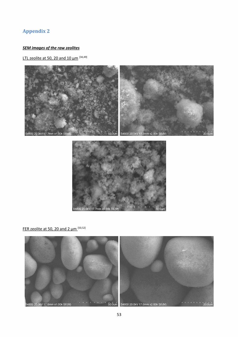
53
Appendix 2
SEM images of the raw zeolites
LTL zeolite at 50, 20 and 10 μm [34,49]
FER zeolite at 50, 20 and 2 μm [50,52]

54
Y330 zeolite at 50 and 20 μm [47,48,51,53]
Y350 zeolite at 50, 20 and 5 μm[47,48,51,53]

55
Y360 zeolite at 50 and 20 mm[47,48,51,53]

56
Appendix 3
Capacity formula
𝐶𝑎𝑝𝑎𝑐𝑖𝑡𝑦 =([𝑅𝐸𝐸]𝑖 − [𝑅𝐸𝐸]𝑒) × 𝑉𝑠𝑜𝑙
𝑚𝑧𝑒𝑜𝑙𝑖𝑡𝑒
With: [REE]i, the initial concentration of REE (in the reference).
[REE)e, the concentration of REE at equilibrium pH (in the samples)
Vsol, the volume of the solution (vial)
Percentage of Al dissolved in the supernatant
%𝐴𝑙𝑑𝑖𝑠𝑠 =
[𝐴𝑙](𝑝𝑝𝑚)
1000 × 𝑉𝑠𝑜𝑙
%𝑤𝐴𝑙(𝐸𝐷𝑋)
With: [Al](ppm), the concentration of Al in the supernatant in ppm given by the MP-AES.
Vsol, the volume of the solution (vial)
%wAl(EDX), the weight percentage of Al in the raw zeolite given by EDX.