Embed Size (px)
Citation preview

602-610 Mamaroneck Avenue, White Plains, NY, 10605, www.ada-usa.com, 1-800-HD-AUDIO, Fax (914) 946-9620
HOME & THEATER
A/V RECEIVER
PRELIMINARY
INSTALLATION &USER MANUAL


HTR-2400 Manual Page 1 Introduction
SAFETY INSTRUCTIONSREAD INSTRUCTIONS - All the safety and operating instructions should be
read before the appliances are operated.
RETAIN INSTRUCTIONS - The operating instructions should be retained forfuture reference.
HEED WARNING - All warnings on the appliances and in the operatinginstructions should be adhered to.
.FOLLOW INSTRUCTIONS - All operating and use instructions should be
followed.
WATER AND MOISTURE - The appliances should not be used near water - forexample, near a bathtub, washbowl, kitchen sink, laundry tub, in a wetbasement, or near a swimming pool, etc.
LOCATION - The appliances should be installed in a stable location.
WALL OR CEILING MOUNT - The appliances should not be mounted to a wallor ceiling.
VENTILATION - The appliances should be situated so that their location orposition does not interfere with their proper ventilation. For example, theappliances should not be situated on a bed, sofa, rug or similar surfacethat may block the ventilation openings.
HEAT - The appliances should be situated away from heat sources such asradiators, heat registers, stoves, or other appliances that produce heat.
POWER SOURCES - The appliances should be connected to a power supplyonly of the type described in the operating instructions or as marked onthe appliances.
GROUNDING - Make sure that the units in the system are always connectedto a standard three-prong grounded outlet (the circular pin is ground).When operating this unit at a higher voltage with a different power cordconfiguration, consult your dealer for the proper power cord/outlet com-bination to use before operating this unit.
POWER CORD PROTECTION - Power supply cords should be routed so thatthey are not likely to be walked on or pinched by items placed upon oragainst them, paying particular attention to cords at plugs, conveniencereceptacles, and the points where they exit from the appliances.
CLEANING - The appliances should be cleaned only with a polishing cloth ora soft dry cloth. Never clean with furniture wax, benzine, insecticides orother volatile liquids since they may corrode the face plates.
POWER LINES - An outdoor antenna should be located away from power lines.
PERIODS OF DISUSE - The power cord of the appliances should be unpluggedfrom the outlet when the units are not in use for a long period of time.
OBJECT AND LIQUID ENTRY - Care should be taken so that objects do notfall and liquids are not spilled into the enclosures through openings.
DAMAGE REQUIRING SERVICE - The appliances should be serviced by anauthorized service center or qualified service personnel when:
• The power supply cords or plugs have been damaged; or• Objects have fallen, or liquid has been spilled into the
appliances; or• The appliances have been exposed to rain; or• The appliances do not appear to operate normally or
exhibit a marked change in performance; or• The appliances have been dropped; or the enclosures have
been damaged.
SERVICING - The user should not attempt to service the appliances beyond thatdescribed in the operating instructions. For all other servicing, contact thefactory.
WARNING:TO REDUCE THE RISK OF FIRE OR ELECTRI-CAL SHOCK, DO NOT EXPOSE THE APPLI-ANCES IN THIS SYSTEM TO RAIN OR MOIS-TURE. REPLACE FUSE ONLY AS MARKED.
CAUTION:TO PREVENT ELECTRIC SHOCK, DO NOTPLUG THE UNITS IN THIS SYSTEM INTO ANYOUTLET OR EXTENSION CORD WITHOUT THESTANDARD THREE-PRONG CONFIGURA-TION, WHERE THE CIRCULAR HOLE IS USEDFOR THE GROUND PLUG.
IMPORTANT:
The exclamation point within the equi-lateral triangle is intended to alert theuser of the presence of important op-erating and maintenance (servicing)instructions in the literature accompa-nying the appliances.
CAUTION:TO PREVENT RISK OF ELECTRICAL SHOCK, DO NOTREMOVE COVER (OR BACK). NO USER-SERVICEABLEPARTS ARE INSIDE ANY OF THE UNITS IN THIS SYSTEM.REFER SERVICING TO QUALIFIED SERVICE PERSON-NEL.
The lightning flash with the arrowhead,within an equilateral triangle, is in-tended to alert the user of the pres-ence of un-insulated "dangerous volt-age" within the products' enclosuresthat may be of sufficient magnitude toconstitute a risk of electrical shock topersons.
CAUTIONRISK OF ELECTRIC SHOCK
DO NOT OPEN

Introduction Page 2 HTR-2400 Manual
Contents
HTR-2400 REAR PANEL CONNECTIONS ..................................... 4 TUNER CONNECTIONS............................................................. 4 SOURCE CONNECTIONS (HOME & THEATER) .............................. 6 SOURCE CONNECTIONS (THEATER ONLY) .................................. 6 MULTI-ROOM SPEAKER & VIDEO OUTPUTS ............................... 8 THEATER SPEAKER, AUDIO & VIDEO OUTPUTS .......................... 8 IR LEARNER - CONNECTIONS & FEATURES.............................. 10 SOURCE AC CONNECTIONS ...................................................11 KEYPAD CONNECTIONS ..........................................................11FRONT PANEL CONTROL.......................................................... 12 SELECTING ROOM SCREENS.................................................. 13 THEATER ZONE SCREEN ....................................................... 14 ALL ROOMS SCREEN ........................................................... 18 ROOM SCREEN (1-8) ........................................................... 20 PARTY GROUP SCREEN ........................................................ 23ENTERING SETUP MODE .......................................................... 24 NAVIGATING SETUP MODE..................................................... 25MULTI-ROOM & GLOBAL SETUPS ............................................. 25 INPUT TRIM SETUP............................................................... 26 PARTY MODE SETUP............................................................ 26 ADA BUS SETUP................................................................ 27 VOLUME SETUP................................................................... 28 BALANCE SETUP ................................................................. 29 TONE SETUP....................................................................... 30 LABELS & SOURCE SETUP ................................................... 32 SOURCE CONTROL SETUP .................................................... 33 AC POWER SETUP .............................................................. 34

HTR-2400 Manual Page 3 Introduction
All specifications subject to change without prior notice.©2005 Audio Design Associates, Inc. All rights reserved.
VERSION INFORMATION ............................................................ 35CLOCK SET ........................................................................... 35FACTORY DEFAULT ................................................................. 35HOME & THEATER SETUP COMPARISONS ................................... 36HOME THEATER SETUP ........................................................... 37 SPEAKER SIZE .................................................................... 38 SPEAKER DELAY ................................................................. 40 SPEAKER LEVEL.................................................................. 42 BALANCE STORE ................................................................. 44 BALANCE RECALL ............................................................... 45 VOLUME PRESETS ............................................................... 46 FINAL INPUT ....................................................................... 48 SOURCE SETUP................................................................... 49 TONE CONTROLS ................................................................. 53 PRO LOGIC IIX .................................................................... 54
PC PROGRAM SETUP - PC CONNECTIONS ................................. 55PC PROGRAM SETUP - MULTI-ROOM ........................................ 56PC PROGRAM SETUP - HOME THEATER .................................... 58PC PROGRAM SETUP - TUNERS ............................................... 63PC PROGRAM SETUP - IR LEARNER......................................... 64
RS-232 CODES - MULTI-ROOM ............................................... 71RS-232 CODES - HOME THEATER ........................................... 72RS-232 CODES - XM TUNER ................................................. 75RS-232 CODES - FM/AM/WX TUNER .................................... 76RS-232 CODES - IRL CODES................................................. 77

Connections - Rear Panel Page 4 HTR-2400 Manual
HomeTheater
AmplifiedAudioOutput
7.1 Channels
All Ouputs8 - 4Do Not Short
Outputs!Do Not Bridge
Outputs!FrontLeft
+ -
SurroundLeft
- +
Center
+ -
Surround BackLeft
Front Right Surround Right Subwoofer Surround Back Right
- +
+ - - + + - - +
AM/FM/WX Radio
(To Input)
AM/FMAntenna
Input
75
Audio Output
L RXM Radio®
(To Input)
XMAntenna
Input
50
Audio Output
L R
+ - - +L R
Room 1(8 - 2 )
+ - - +L R
Room 2(8 - 2 )
+ - - +L R
Room 3(8 - 2 )
+ - - +L R
Room 4(8 - 2 )
+ - - +L R
Room 5(8 - 2 )
+ - - +L R
Room 6(8 - 2 )
+ - - +L R
Room 7(8 - 2 )
+ - - +L R
Room 8(8 - 2 )
Room Keypad Control Connections • Use Any RJ-45 Port ADA Bus® Port RS-232 Port Theater Trigger
RJ-45 Ports Are Not Room Specific • Cat. 5 Wire Is Straight-Through 1 2 3 4 1( -) 2 (+ )
Gnd +VDCOut In
TX RX
Straight Through 12VDC Output
Set RS-232 SwitchSee IRL-5000
Component Video OutputY PB PR
Component Video Input 2
Component Video Input 1
Y PB PR
Component Video Input 3Y PB PRY PB PR
VideoIn
VideoOut
Source 2 Source 4 Source 6 Source 8
Source 1 Source 3 Source 5 Source 7
Room 5Room 7 Room 3 Room 1 &Theater
Room 8 Room 6 Room 4 Room 2
S-Video Out
2
1
S-Video Inputs
2
1
4
3
IR Emitter Outputs
RS-232Switch
IR Receiver (Learner)IRL-5000
IR LearnMode
(IRL-5000)
NormalMode
(PC Setup & RS-232Control)
Source 8 Source 7 Source 6 Source 5 Source 4 Source 3 Source 2 Source 1
Switched AC2.5 Amp Max
Per Outlet
AC4
AC3
AC2
AC1
CAUTIONRISK OF ELECTRIC SHOCK
DO NOT OPEN
ATTENTION!RISQUE DE CHOC ELECTRIQUE.
NE PAS OUVRIR
MADE IN U.S.A.
CAUTION:Disconnect Supply Cord Before Servicing.
ATTENTION:Debrancher Avant Le Depannage.
120VAC~60Hz
1200W
230VAC~50Hz
1200W
10ASB115V
5ASB230V
If Box Red
HTR-2400 REAR PANEL CONNECTIONS
To ensure that proper connections are maintained, wire management needs to be consid-ered. It is recommended that wires and cables be fastened in such a way that as much oftheir weight as possible be secured to something other than the actual connector or jack onthe HTR-2400. For pull out racks, make certain that there is enough room behind the rack topermit the wires and cables to retract without pinching, pulling or crunching.
TUNER CONNECTIONSThe HTR-2400 features two tuner modules. Atthe time of this printing, the modules availableare an XM Radio Module and an FM/AM/WX(Weatherband) radio module. These modules,like all of the HTR-2400’s rear-panel assembly,are cards that slide in and out of the chassis ontracks. As such, they can be updated or re-moved.
The tuner modules feature an antenna input anda stereo audio output. In order to hear the out-put of these tuners, you need to loop this audiooutput to inputs on the HTR-2400. Typically, youwill loop Tuner Module one (far left side of rearpanel) to Audio Input 1 and Tuner Module 2 toAudio Input 2 as show to the right.
AM/FM/WX Radio
(To Input)
AM/FMAntenna
Input
75
Audio Output
L RXM Radio®
(To Input)
XMAntenna
Input
50
Audio Output
L R
+ - - +L R
Room 1(8 - 2 )
+ - - +L R
Room 2(8 - 2 )
+ - - +L R
Room 3(8 - 2 )
+ - - +L R
Room 4(8 - 2 )
+ - - +L R
Room 5(8 - 2 )
+ - - +L R
Room 6(8 - 2 )
+ - - +L R
Room 7(8 - 2 )
TX RX
VideoIn
Source 2 Source 4 Source 6 Source 8
Source 1 Source 3 Source 5 Source 7
Room
Room
IR Emitter Outpu
RS-232Switch
IR Receiver (LearIR LearnMode
(IRL-5000)
NormalMode
(PC Setup & RS-232Control)
Source 8 Source 7 Source 6 Source 5 Source 4
When installing the HTR-2400, you will need to connect audio and video sources for thehome and theater, digital sources and S-Video/Component video for the theater, antennaconnections for the tuners, AC and IR source connections, keypads, perhaps RS-232, speakerlines for the house, speaker lines for the theater, perhaps line-level theater outputs, low-voltage triggers for theater, and record analog, digital and S-Video outputs.

HTR-2400 Manual Page 5 Connections - Rear Panel
AM/FM/WX Radio
(To Input)
AM/FMAntenna
Input
75
Audio Output
L RXM Radio®
(To Input)
XMAntenna
Input
50
Audio Output
L R
+ - - +L R
Room 1(8 - 2 )
+ - - +L R
Room 2(8 - 2 )
+ - - +L R
Room 3(8 - 2 )
+ - - +L R
Room 4(8 - 2 )
+ - - +L R
Room 5(8 - 2 )
+ - - +L R
Room 6(8 - 2 )
+ - - +L R
Room 7(8 - 2 )
TX RX
VideoIn
Source 2 Source 4 Source 6 Source 8
Source 1 Source 3 Source 5 Source 7
Room 7
Room 8
IR Emitter Outputs
RS-232Switch
IR Receiver (LearneIR LearnMode
(IRL-5000)
NormalMode
(PC Setup & RS-232Control)
Source 8 Source 7 Source 6 Source 5 Source 4 S
FM Roof Antenna(or other FM Antenna)
To XMTuner
12VDCPower
PowerLED
From ACB-1 (200' RG6 Max!)
To FM/AMTuner
ACB-2
XM Ant.Input
Combined Ant.Output to ACB-2
PowerLED
AMAnt. Input
FM/WXAnt. Input ACB-1
AM/FM/WX Radio
AM/FMAntenna
Input
75
L RXM Radio®
XMAntenna
Input
50
L R
+ - - +L R
Room 1(8 - 2 )
+ - - +L R
Room 2(8 - 2 )
+ - - +L R
Room 3(8 - 2 )
+ - - +L R
Room 4(8 - 2 )
+ - - +L R
Room 5(8 - 2 )
+ - - +L R
Room 6(8 - 2 )
TX RX
VideoIn
Source 2 Source 4 Source 6 Sourc
Source 1 Source 3 Source 5 Sourc
IR Em
RS-232Switch
IR ReceIR LearnMode
(IRL-5000)
NormalMode
(PC Setup & RS-232Control)
Source 8 Source 7 Source 6 Sou
To XMTuner
12VDCPower
PowerLED
From ACB-1 (200' RG6 Max!)
To FM/AMTuner
ACB-2
XM Ant.Input
Combined Ant.Output to ACB-2
PowerLED
AMAnt. Input
FM/WXAnt. Input ACB-1
Use Exactly 6' of RG6For AM Loop Antenna Connection
Run Up To 200 Feet Of RG6Between ACB-1 and ACB-2
12VDC500mA
ACB-2
ACB-1
PowerLED
PowerLED
AML-1AM Loop Antenna(Hang AML-1 and
rotate for bestreception.)
FM Roof Antenna(or other FM Antenna)
For basic antenna connec-tions, one can run the radioantenna directly into the HTR-2400’s FM/AM/WX Module.Please note, that in order to getboth FM and AM, you will need to provide the re-quired antennas and combining components. TheXM Antenna, provided with the HTR-2400 can beconnected to the HTR-2400. Again, placement ofthe XM antenna needs to be in such a manner that XM Radio reception is possible.
ADA also provides the ACB Antenna Combiner Boxes (ACB-1 and ACB-2) which take boththe FM antenna, AM antenna, and XM antenna and combine these signals on a single RG-6type coax cable. This cable can be run up to 200 feet to the HTR-2400’s equipment rack. TheACB-1 and ACB-2 are sold as a set and the AML-1 AM Loop Antenna is sold separately.
Connections - Rear Panel Page 6 HTR-2400 Manual
SOURCE CONNECTIONS (HOME & THEATER)
HomeTheater
AmplifiedAudioOutput
7.1 Channels FrontLeft
+ -
SurroundLeft
- +
Front Right Surround Right+ - - +
+ - - +L R
Room 4(8 - 2 )
+ - - +L R
Room 5(8 - 2 )
+ - - +L R
Room 6(8 - 2 )
+ - - +L R
Room 7(8 - 2 )
+ - - +L R
Room 8(8 - 2 )
Room Keypad Control Connections • Use Any RJ-45 Port ADA B
RJ-45 Ports Are Not Room Specific • Cat. 5 Wire Is Straight-Through 1
Gnd O
TX RX
Component VY PB
Component Video Input 2
Component Video Input 1
Y PB PR
Component ViY PBY PB PR
VideoIn
VideoOut
Source 2 Source 4 Source 6 Source 8
Source 1 Source 3 Source 5 Source 7
Room 5Room 7 Room 3 Room 1 &Theater
Room 8 Room 6 Room 4 Room 2
IR Emitter Outputs
RS-232Switch
IR Receiver (Learner)IRL-5000
IR LearnMode
(IRL-5000)
NormalModeC Setup RS-232
Control)
Source 8 Source 7 Source 6 Source 5 Source 4 Source 3 Source 2 Source 1
AUXILIARYDVD PLAYER
CABLE BOXSATELLITE
CD LIBRARY
CD PLAYER
CompY
Component Video Input 2
Component Video Input 1
Y PB PR
CompYY PB PR
VideoIn
VideoOut
Source 2 Source 4 Source 6 Source 8
Source 1 Source 3 Source 5 Source 7
Room 5Room 7 Room 3 Room 1 &Theater
Room 8 Room 6 Room 4 Room 2
AUXILIARY or VCRCABLE BOX
SATELLITEDVD PLAYER
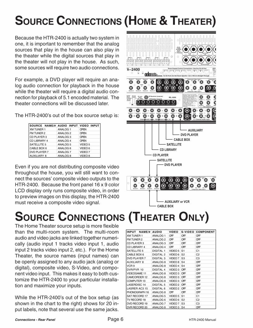
Because the HTR-2400 is actually two system inone, it is important to remember that the analogsources that play in the house can also play inthe theater while the digital sources that play inthe theater will not play in the house. As such,some sources will require two audio connections.
For example, a DVD player will require an ana-log audio connection for playback in the housewhile the theater will require a digital audio con-nection for playback of 5.1 encoded material. Thetheater connections will be discussed later.
The HTR-2400’s out of the box source setup is:
Even if you are not distributing composite videothroughout the house, you will still want to con-nect the sources’ composite video outputs to theHTR-2400. Because the front panel 16 x 9 colorLCD display only runs composite video, in orderto preview images on this display, the HTR-2400must receive a composite video signal.
SOURCE NAME/# AUDIO INPUT VIDEO INPUTXM TUNER 1 ANALOG 1 OPENFM TUNER 2 ANALOG 2 OPENCD PLAYER 3 ANALOG 3 OPENCD LIBRARY 4 ANALOG 4 OPENSATELLITE 5 ANALOG 5 VIDEO 5CABLE BOX 6 ANALOG 6 VIDEO 6DVD PLAYER 7 ANALOG 7 VIDEO 7AUXILIARY 8 ANALOG 8 VIDEO 8
SOURCE CONNECTIONS (THEATER ONLY)INPUT NAME/# AUDIO VIDEO S-VIDEO COMPONENTXM TUNER 1 ANALOG 1 OFF OFF OFFFM TUNER 2 ANALOG 2 OFF OFF OFFCD PLAYER 3 ANALOG 3 OFF OFF OFFCD LIBRARY 4 ANALOG 4 OFF OFF OFFSATELLITE 5 DIGITAL 1 VIDEO 5 S1 C1CABLE BOX 6 DIGITAL 2 VIDEO 6 S2 C2DVD PLAYER 7 DIGITAL 3 VIDEO 7 S3 C3AUXILIARY 8 ANALOG 8 VIDEO 8 S4 OFFVCR 9 ANALOG 8 VIDEO 4 S4 OFFDVR/PVR 10 DIGITAL 4 VIDEO 3 OFF OFFVIDEOGAME 11 ANALOG 8 VIDEO 3 OFF OFFCAMCORDER 12 ANALOG 8 VIDEO 3 OFF OFFCOMPUTER 13 ANALOG 8 VIDEO 3 OFF OFFLASERDISC 14 DIGITAL 5 VIDEO 2 OFF OFFLASRER AC3 15 DIGITAL 6 VIDEO 2 OFF OFFPHONOGRAPH 16 ANALOG 8 OFF OFF OFFSAT RECORD 17 ANALOG 5 VIDEO 5 S1 C1TV RECORD 18 ANALOG 6 VIDEO 6 S2 C2DVD RECORD 19 ANALOG 7 VIDEO 7 S3 C3DVR RECORD 20 ANALOG 8 VIDEO 3 S4 OFF
The Home Theater source setup is more flexiblethan the multi-room system. The multi-roomaudio and video jacks are linked together numeri-cally (audio input 1 tracks video input 1, audioinput 2 tracks video input 2, etc.). For the HomeTheater, the source names (input names) canbe openly assigned to any audio jack (analog ordigital), composite video, S-Video, and compo-nent video input. This makes it easy to both cus-tomize the HTR-2400 to your particular installa-tion and maximize your inputs.
While the HTR-2400’s out of the box setup (asshown in the chart to the right) shows for 20 in-put labels, note that several use the same jacks.

HTR-2400 Manual Page 7 Connections - Rear Panel
Component Video OutputY PB PR
Component Video Input 2
Component Video Input 1
Y PB PR
Component Video Input 3Y PB PRY PB PR
Room 1 &Theater
Room 2
S-Video Out
2
1
S-Video Inputs
2
1
4
3
AUXILIARY or VCRCABLE BOX
SATELLITEDVD PLAYER
Component Video OutputY PB PR
Component Video Input 2
Component Video Input 1
Y PB PR
Component Video Input 3Y PB PRY PB PR
VideoOut
Room 5m 7 Room 3 Room 1 &Theater
m 8 Room 6 Room 4 Room 2
S-Video Out
2
1
S-Video Inputs
2
1
4
3
CABLE BOX
SATELLITEDVD PLAYER
DVR/PVR (Theater Only)LASER DISC AC-3 (Theater Only)
CABLE BOX
SATELLITEDVD PLAYER
LASER DISC PCM (Theater Only)
CompY
Component Video Input 2
Component Video Input 1
Y PB PR
CompYY PB PR
VideoIn
VideoOut
Source 2 Source 4 Source 6 Source 8
Source 1 Source 3 Source 5 Source 7
Room 5Room 7 Room 3 Room 1 &Theater
Room 8 Room 6 Room 4 Room 2
VCR (If Auxiliary is already used.)LASER DISC (Theater Only)
DVR/PVR (Theater Only)
uts
rner)IRL-5000
4 Source 3 Source 2 Source 1
6 CHANNEL DVD AUDIO INPUT
Because you can limit the number of inputs dis-played, rename the source names, reassignjacks, this setup serves only as an example ofwhat can be done and corresponds to the HTR-2400’s out of the box factory default setup.
For digital audio sources, if coax type connec-tions are available, ADA suggests using theseover TOS-Link connectors. When using TOS-Link interconnects ADA suggests using the bestcaliber cable available (frosted tip or convex tip).TOS-Link cables have been known to reflectagainst the TOS-Link receiver causing for audiodropouts. Better cables help prevent this.
For DVD Audio discrete 5.1 playback, a six-chan-nel analog bypass input is used on the HTR-2400. Please note, that in order to access thisinput, you will need to select a source name thatis not used, relabel it to read DVD AUDIO, andassign the audio input to ANALOG BYPAS.
Because the HTR-2400’s Home Theater hasopen input assignment, it can use open (or un-used) composite video inputs. In a commonsetup, house inputs 1-4 are used by the tunersand CD players and these devices typically donot output any video. As such, the Home The-ater can use these video inputs for theater spe-cific sources like a DVR, VCR or Laser Discplayer.
The S-Video switcher of the HTR-2400 permitsfour S-Video signals to be routed to two outputs.Both outputs play the same signal. Please notethat an S-Video input only comes out of an S-Video output.
The component video switcher of the HTR-2400permits three component video signals to berouted to one component video output. The com-ponent video output only routes component videoinputs. If you wish to view composite or S-Videosources on your display, you will need to con-nect both composite video, S-Video and compo-nent video from the HTR-2400 to your displaydevice.

Connections - Rear Panel Page 8 HTR-2400 Manual
MULTI-ROOM SPEAKER & VIDEO OUTPUTS
+ - - +L R
Room 1(8 - 2 )
+ - - +L R
Room 2(8 - 2 )
+ - - +L R
Room 3(8 - 2 )
+ - - +L R
Room 4(8 - 2 )
+ - - +L R
Room 5(8 - 2 )
+ - - +L R
Room 6(8 - 2 )
+ - - +L R
Room 7(8 - 2 )
+ - - +L R
Room 8(8 - 2 )
RM 1 RM 2 RM 3 RM 4 RM 5 RM 6 RM 7 RM 8
DO NOT SHORT GROUNDS!DO NOT SHORT SPEAKER!
DO NOT BRIDGE CHANNELS!STABLE TO 2 OHMS!
GROUND (-) FOR LEFT AND RIGHTCHANNELS ARE INDEPENDENT.
Component Video OutputY PB PR
Component Video Input 2
Component Video Input 1
Y PB PR
Component Video Input 3Y PB PRY PB PR
VideoIn
VideoOut
Source 2 Source 4 Source 6 Source 8
Source 1 Source 3 Source 5 Source 7
Room 5Room 7 Room 3 Room 1 &Theater
Room 8 Room 6 Room 4 Room 2
S-Vide
2
1
ROOM 2ROOM 6
ROOM 1 / HOME THEATERROOM 7
ROOM 4ROOM 8
ROOM 3ROOM 5
The HTR-2400 provides class D (digital) poweramplification for the eight rooms in the house.Each zone output is stable down to 2 Ohms butbest performance will be achieved when operat-ing speaker loads in the 8-4 Ohm range. Theroom amplifier channels are bridged. This meansthat the ground (-) is unique to the left and rightchannels. You cannot short the grounds togetherbecause they are not common. Because of theclose proximity of all speaker outputs, pay closeattention to cleanly terminate speaker wires.
Each zone also has a composite videooutput. These can be used to providevideo to local TVs or video capabletouch-screens.
Room 1 shares its video output withHome Theater zone. If any of the HomeTheater sources have their compositevideo active (set to ON), even if thatsource is not selected, then as Room 1 selects a source, video will not follow. However if theHome Theater is only being driven by S-Video or component video and all home theatersources have composite video set to OFF, then when an input is selected for Room 1, thevideo will follow. This feature permits you to determine if Room 1 is a video capable zone ornot. For a flexible Home Theater setup, ADA suggests assigning Room 1 to a zone that doesnot have a video display.
THEATER SPEAKER, AUDIO & VIDEO OUTPUTS
HomeTheater
AmplifiedAudioOutput
7.1 Channels
All Ouputs8 - 4Do Not Short
Outputs!Do Not Bridge
Outputs!FrontLeft
+ -
SurroundLeft
- +
Center
+ -
Surround BackLeft
Front Right Surround Right Subwoofer Surround Back Right
- +
+ - - + + - - +
SURROUND BACK LEFT
CENTER
FRONT LEFT
SURROUND LEFT
SUBWOOFER
SURROUND BACK RIGHT
SURROUND RIGHT
FRONT RIGHT
DO NOT SHORT SPEAKERS & BRIDGE CHANNELS!STABLE TO 4 or 2 OHMS BASED ON SIDE PANEL
AMPLIFIER IMPEDANCE SWITCH POSITION.
The HTR-2400 features a Class A/B high-current power amplifier for the Home The-ater zone. This amplifier is stable to 4 Ohms.Do not attempt to bridge this amplifier. Ifyou are using active subwoofers and/or arenot using back surround speakers, you canleave these speaker channels unused.Make certain that your speaker connectionsare clean and secure.
High Power8 To 4 Ohms
Standard Power4 To 2 Ohms
HTR-2400Theater AmpImpedance
Switch
HTR-2400ChassisLeft Side
The HTR-2400 features a Theater Amplifier Impedance Switchlocated on the left side of the chassis. In the up position, youwill get more power but the amplifier is only stable to 4 Ohms.In the down position, the amplifier is stable to 2 Ohms.

HTR-2400 Manual Page 9 Connections - Rear Panel
IR Emitter Outputs
RS-232Switch
IR Receiver (Learner)IRL-5000
IR LearnMode
(IRL-5000)
NormalMode
(PC Setup & RS-232Control)
Source 8 Source 7 Source 6 Source 5 Source 4 Source 3 Source 2 Source 1
SUBWOOFER
SURROUND BACK RIGHT
SURROUND BACK LEFT
CENTER
SURROUND RIGHT
FRONT RIGHT
FRONT LEFT
SURROUND LEFT
Component Video OutputY PB PR
Component Video Input 2
Component Video Input 1
Y PB PR
Component Video Input 3Y PB PRY PB PR
VideoIn
VideoOut
e 2 Source 4 Source 6 Source 8
e 1 Source 3 Source 5 Source 7
Room 5Room 7 Room 3 Room 1 &Theater
Room 8 Room 6 Room 4 Room 2
S-Video Out
2
1
S-Video Inputs
2
1
4
3
HOME THEATER
RECORDING DEVICEHOME THEATER/ROOM 1
HOME THEATER
The HTR-2400 also features line-level audio outputs for the home theater zone. In manycases, while you may be using the power amplifier in the HTR-2400 for all of the theater’sspeakers, you may need to use its line-level audio outputs for connection to a self-powered(active) subwoofer. Alternately, you can connect additional power amplifiers or a multi-chan-nel power amplifier to the HTR-2400.
ofer Surround Back Right
ort RS-232 Port Theater Trigger
4 1( -) 2 (+ )
DC Straight Through 12VDC Output
Set RS-232 SwitchSee IRL-5000
ut
3
S-Video Out
2
1
S-Video Inputs
2
1
4
3
AC2
AC1
CAUTION:Disconnect Supply Cord Before Servicing.
ATTENTION:Debrancher Avant Le Depannage.
120VAC~60Hz
1200W
230VAC~50Hz
1200W
10ASB115V
5ASB230V
If Box Red
2 CONDUCTOR LOW VOLTAGE WIRE
Bypass Trigger
All-On Trigger
230V~ 5 ASB 115V~ 10 ASB
MAIN FUSE
230V~1/10 ASB
115V~2/10 ASB
STBY FUSE
CAUTIONRISK OF ELECTRIC SHOCK
DO NOT OPEN
ATTENTION!RISQUE DE CHOC ELECTRIQUE.
NE PAS OUVRIR
MADE IN U.S.A.
230V
230V
115V
115V
1200WATTS
MAX
All Channels12VDC1(-) 2(+)
-6Ω
115 V
115 V
1 2
HomeTheater
AmplifiedAudioOutput
7.1 Channels
All Ouputs8 - 4Do Not Short
Outputs!Do Not Bridge
Outputs!FrontLeft
+ -
SurroundLeft
- +
Center
+ -
Surround BackLeft
Front Right Surround Right Subwoofer Surround Back Right
- +
+ - - + + - - +
AM/FM/WX Radio
(To Input)
AM/FMAntenna
Input
75
Audio Output
L RXM Radio®
(To Input)
XMAntenna
Input
50
Audio Output
L R
+ - - +L R
Room 1(8 - 2 )
+ - - +L R
Room 2(8 - 2 )
+ - - +L R
Room 3(8 - 2 )
+ - - +L R
Room 4(8 - 2 )
+ - - +L R
Room 5(8 - 2 )
+ - - +L R
Room 6(8 - 2 )
+ - - +L R
Room 7(8 - 2 )
+ - - +L R
Room 8(8 - 2 )
Room Keypad Control Connections • Use Any RJ-45 Port ADA Bus® Port RS-232 Port Theater Trigger
RJ-45 Ports Are Not Room Specific • Cat. 5 Wire Is Straight-Through 1 2 3 4 1( -) 2 (+ )
Gnd +VDCOut In
TX RX
Straight Through 12VDC Output
Set RS-232 SwitchSee IRL-5000
Component Video OutputY PB PR
Component Video Input 2
Component Video Input 1
Y PB PR
Component Video Input 3Y PB PRY PB PR
VideoIn
VideoOut
Source 2 Source 4 Source 6 Source 8
Source 1 Source 3 Source 5 Source 7
Room 5Room 7 Room 3 Room 1 &Theater
Room 8 Room 6 Room 4 Room 2
S-Video Out
2
1
S-Video Inputs
2
1
4
3
IR Emitter Outputs
RS-232Switch
IR Receiver (Learner)IRL-5000
IR LearnMode
(IRL-5000)
NormalMode
(PC Setup & RS-232Control)
Source 8 Source 7 Source 6 Source 5 Source 4 Source 3 Source 2 Source 1
Switched AC2.5 Amp Max
Per Outlet
AC4
AC3
AC2
AC1
CAUTIONRISK OF ELECTRIC SHOCK
DO NOT OPEN
ATTENTION!RISQUE DE CHOC ELECTRIQUE.
NE PAS OUVRIR
MADE IN U.S.A.
CAUTION:Disconnect Supply Cord Before Servicing.
ATTENTION:Debrancher Avant Le Depannage.
120VAC~60Hz
1200W
230VAC~50Hz
1200W
10ASB115V
5ASB230V
If Box Red
2 CONDUCTOR LOW VOLTAGE WIRE
Bypass Trigger
All-On Trigger
230V~ 5 ASB 115V~ 10 ASB
MAIN FUSE
230V~1/10 ASB
115V~2/10 ASB
STBY FUSE
CAUTIONRISK OF ELECTRIC SHOCK
DO NOT OPEN
ATTENTION!RISQUE DE CHOC ELECTRIQUE.
NE PAS OUVRIR
MADE IN U.S.A.
230V
230V
115V
115V
1200WATTS
MAX
Typical Power: 250-600 WattsUltimate Max. Power: 1200 WattsAverage Thermal Load: 2048 BTU/Hr
All Channels12VDC1(-) 2(+)
PTM-81508 Channel Power Amplifer
Warning! Do Not Short OutputsWARNING! Risk Of Hazardous Energy! Make Proper Connections.
AVERTISSEMENT! Energie Electrique Dangereuse! Faire Des Connexions Propres Pour L'Hautparleur. Voir La Notice De Fonctionnement.
CAUTION: Disconnect Supply Cord Before Servicing.ATTENTION: Debrancher Avant Le Depannage.
+-OUTPUT 2-16 Ω INPUT
47KΩ CH1
-+OUTPUT 2-16Ω
-+OUTPUT 2-16Ω
-+OUTPUT 2-16Ω
-+OUTPUT 2-16Ω
+-OUTPUT 2-16 INPUT
47K CH2
Ω+-
OUTPUT 2-16 Ω INPUT47K CH
3+-
OUTPUT 2-16 INPUT47KΩ
INPUT47KΩ
INPUT47KΩ
INPUT47K Ω
INPUT47KΩ
CH4
CH5
CH6
CH7
CH8
Ω
115 V
115 V
1 2
In the event that you are using an external poweramplifier in the Home Theater, the HTR-2400features a low-voltage trigger output (12VDC)that can be used to trigger an ADA power ampli-fier. Using a 2-conductor low-voltage wire, con-nect the HTR-2400 trigger to the trigger input onthe ADA power amplifier (set the amplifier Trig-ger Switch accordingly). You will also need toset the DC Trigger to ON when programming theHTR-2400 Theater Sources.
The HTR-2400 videooutputs connect to theTheater’s video display.The extra S-Video out-put can connect to arecording device.
ANALOG AUDIO RECORD OUTPUT
DIGITALAUDIORECORDOUTPUT
The HTR-2400 features an analog and digital au-dio output which track the source playing in thetheater. These can be connected to recordingdevices. The analog output only passes analogsources and the digital output only passes digi-tal sources.
Connections - Rear Panel Page 10 HTR-2400 Manual
IR Emitter Outputs
RS-232Switch
IR Receiver (Learner)IRL-5000
IR LearnMode
(IRL-5000)
NormalMode
(PC Setup & RS-232Control)
Source 8 Source 7 Source 6 Source 5 Source 4 Source 3 Source 2 Source 1
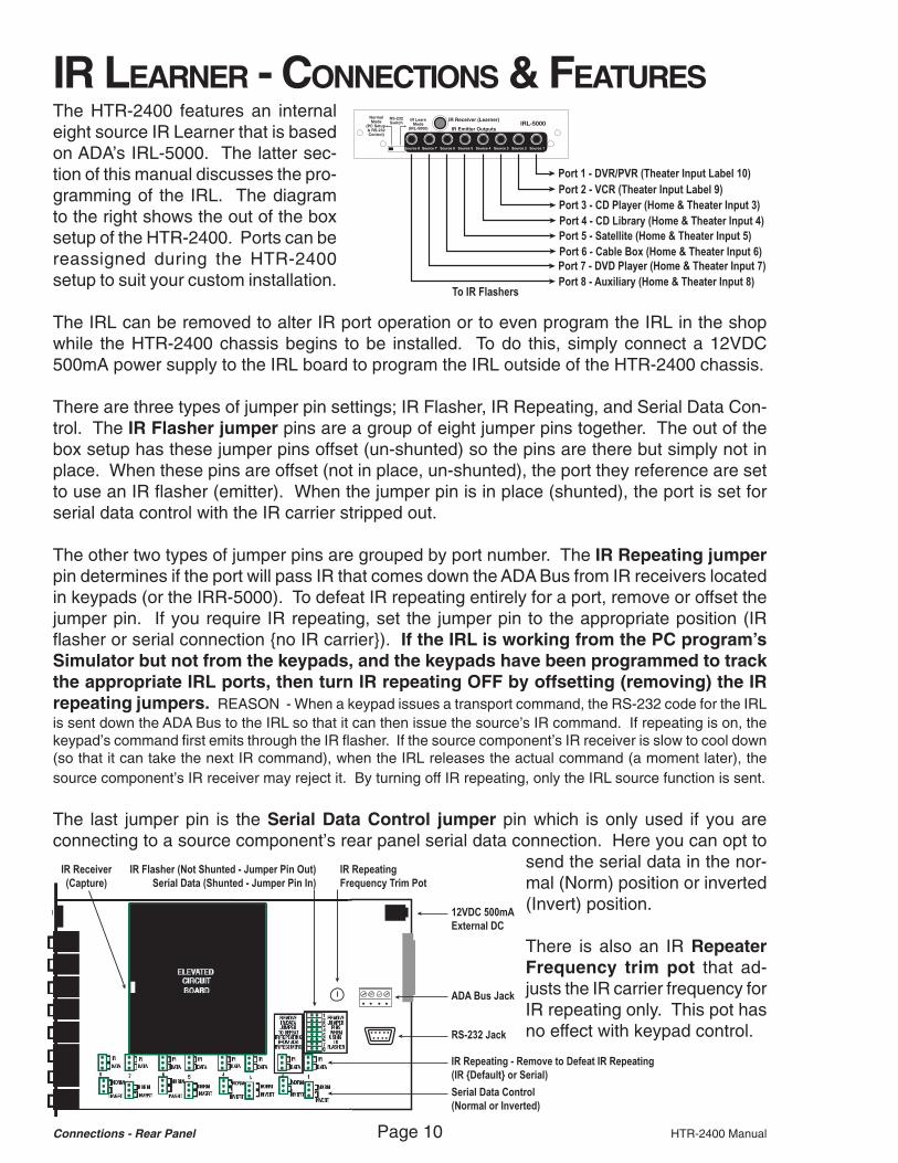
Port 1 - DVR/PVR (Theater Input Label 10)Port 2 - VCR (Theater Input Label 9)Port 3 - CD Player (Home & Theater Input 3)Port 4 - CD Library (Home & Theater Input 4)Port 5 - Satellite (Home & Theater Input 5)Port 6 - Cable Box (Home & Theater Input 6)Port 7 - DVD Player (Home & Theater Input 7)Port 8 - Auxiliary (Home & Theater Input 8)
To IR Flashers
12VDC 500mAExternal DC
IR RepeatingFrequency Trim Pot
IR Receiver(Capture)
IR Flasher (Not Shunted - Jumper Pin Out)Serial Data (Shunted - Jumper Pin In)
ADA Bus Jack
RS-232 Jack
IR Repeating - Remove to Defeat IR Repeating(IR Default or Serial)
Serial Data Control(Normal or Inverted)
IR LEARNER - CONNECTIONS & FEATURESThe HTR-2400 features an internaleight source IR Learner that is basedon ADA’s IRL-5000. The latter sec-tion of this manual discusses the pro-gramming of the IRL. The diagramto the right shows the out of the boxsetup of the HTR-2400. Ports can bereassigned during the HTR-2400setup to suit your custom installation.
The IRL can be removed to alter IR port operation or to even program the IRL in the shopwhile the HTR-2400 chassis begins to be installed. To do this, simply connect a 12VDC500mA power supply to the IRL board to program the IRL outside of the HTR-2400 chassis.
There are three types of jumper pin settings; IR Flasher, IR Repeating, and Serial Data Con-trol. The IR Flasher jumper pins are a group of eight jumper pins together. The out of thebox setup has these jumper pins offset (un-shunted) so the pins are there but simply not inplace. When these pins are offset (not in place, un-shunted), the port they reference are setto use an IR flasher (emitter). When the jumper pin is in place (shunted), the port is set forserial data control with the IR carrier stripped out.
The other two types of jumper pins are grouped by port number. The IR Repeating jumperpin determines if the port will pass IR that comes down the ADA Bus from IR receivers locatedin keypads (or the IRR-5000). To defeat IR repeating entirely for a port, remove or offset thejumper pin. If you require IR repeating, set the jumper pin to the appropriate position (IRflasher or serial connection no IR carrier). If the IRL is working from the PC program’sSimulator but not from the keypads, and the keypads have been programmed to trackthe appropriate IRL ports, then turn IR repeating OFF by offsetting (removing) the IRrepeating jumpers. REASON - When a keypad issues a transport command, the RS-232 code for the IRLis sent down the ADA Bus to the IRL so that it can then issue the source’s IR command. If repeating is on, thekeypad’s command first emits through the IR flasher. If the source component’s IR receiver is slow to cool down(so that it can take the next IR command), when the IRL releases the actual command (a moment later), thesource component’s IR receiver may reject it. By turning off IR repeating, only the IRL source function is sent.
The last jumper pin is the Serial Data Control jumper pin which is only used if you areconnecting to a source component’s rear panel serial data connection. Here you can opt to
send the serial data in the nor-mal (Norm) position or inverted(Invert) position.
There is also an IR RepeaterFrequency trim pot that ad-justs the IR carrier frequency forIR repeating only. This pot hasno effect with keypad control.

HTR-2400 Manual Page 11 Connections - Rear Panel
SOURCE AC CONNECTIONSSwitched AC2.5 Amp Max
Per Outlet
AC4
AC3
AC2
AC1
CAUTIONRISK OF ELECTRIC SHOCK
DO NOT OPEN
ATTENTION!RISQUE DE CHOC ELECTRIQUE.
NE PAS OUVRIR
MADE IN U.S.A.
CAUTION:Disconnect Supply Cord Before Servicing.
ATTENTION:Debrancher Avant Le Depannage.
120VAC~60Hz
1200W
230VAC~50Hz
1200W
10ASB115V
5ASB230V
If Box Red AC Power Outlet (At least 10A @ 115V)(Unit will be marked if configured for 230V/50Hz operation.)
CD Player - Input 3 (Home & Theater)
CD Library - Input 4 (Home & Theater)
DVD Player - Input 7 (Home & Theater)
Auxiliary - Input 8 (Home & Theater)
The HTR-2400 features four switched AC out-lets for turning sources on and off based on us-age. These outlets should not be used withhi-current drawing components such aspower amplifiers.
The HTR-2400’s out of the box setup has thesefour outlets assigned to the CD Player, CD Li-brary, DVD Player and Auxiliary inputs. You canreassign their usage during the setup of sourcesfor both the home and theater.
If the HTR-2400 has been internally modified for230VAC - 50Hz operation, the small square tothe left of the EIC AC receptacle will be marked.
KEYPAD CONNECTIONS Room Keypad Control Connections • Use Any RJ-45 Port ADA Bus® Port RS-232 Port Theater Trigger
RJ-45 Ports Are Not Room Specific • Cat. 5 Wire Is Straight-Through 1 2 3 4 1( -) 2 (+ )
Gnd +VDCOut In Straight Through 12VDC Output
Set RS-232 SwitchSee IRL-5000
To ADA Keypads(Position Does
Not Matter)
To Additional ADA BusDevices or Components
(iHome Multi-Center, MSC-1,ISO-E, ISO-USB, etc.)
The rear panel ADA Bus port will not poweradditional ADA Bus keyapds!
To RS-232Control System
RJ-45 Cat. 5 Cable Connector
TopFront
BROWN
BROWN
WHITE
GREEN
WHITE
ORANGE
ORANGE
WHITE
GREEN
BLUE
BLUE
WHITE
8 7 6 5 4 3 2 1
PIN NUMBER COLOR FUNCTIONPIN 1 BROWN +20VPIN 2 BROWN/WHITE GNDPIN 3 GREEN/WHITE TX-PIN 4 ORANGE RX+PIN 5 ORANGE/WHITE RX-PIN 6 GREEN TX+PIN 7 BLUE +20VPIN 8 BLUE/WHITE GND
RJ-45 Cat. 5 Cable Connector
TopFront
BROWN
WHITE
GREEN
WHITE
ORANGE
ORANGE
WHITE
GREEN
BLUE
8 7 6 5 4 3 2 1
ADA keypads connect directly to the HTR-2400’s eight RJ-45 female connectors. Thesuggested wire is standard Cat. 5 cable.Wiring is the most critical aspect of an ADAinstallation. ADA keypads wire straight-through (no crisscross). Make certain thatyour wiring is free of error or damage priorto connecting keypads! The diagram andchart to the right show a typical Cat. 5 to RJ-45 connection. Your color code may vary butit is critical that point to point connections bein tact.
If you need to connect additional ADA key-pads, please contact ADA as to the best re-sult based on the number of extra keypadsneeded. The HTR-2400’s ADA Bus jack can-not simply connect to another ADA wire har-ness (i.e. WH-2000) and then to more key-pads because the power supply on the ADABus jack is not designed to drive keypads. Inorder for this to function, an additional power-supply will most likely be required.
In the event your Cat. 5 cable is damaged,you can still get full operation by leaving offboth pins 1 & 8 (leave both wires off even ifyou have 7 good Cat. 5 wires).

Operation Instructions Page 12 HTR-2400 Manual
+ - SELECT MENU OFF
FRONT PANEL CONTROLThe HTR-2400’s easy to use front panel permitsyou to control the entire home. The buttons flank-ing the LCD display are source transport func-tions (source control). How these operate willdepend on how your custom installation profes-sional programmed the HTR-2400’s infraredlearner (IRL). Because the two tuners are inter-nal to the HTR-2400 and are not controlled bythe IRL, their operation is explained below.
To the left of the color LCD displayare numeric source transport but-tons including * and Enter. There isalso the black Master Power switchlocated to the far left of the bezel.
The right side of the display fea-tures additional source transportbuttons including play, stop,pause, reverse play, forward, re-wind and navigation buttons.
The Master Power switch needs to be pushed in for the HTR-2400 to operate. When servic-ing the system, it is wise to turn this button off. Turning the button off is similar to unpluggingthe HTR-2400.
XM Radio Tuner Operation (Also on keypads)0-9 & ENTER - Access XM channel numbers.* - Updates the current channel & song info.<< & >> - Advances channels down & up.< & > - Advances through XM genres.|| & [] - Advances through channels in a genre.MAIN - Advances through presets (preset skip up).Up & Down - Preset skips up and down.
Storing An XM Station As A PresetWhen on a station that you wish to store as a preset,press 0 twice and then press ENTER. You will beprompted to “STORE? PR #”. If this preset number isright, press ENTER to store this as one of the 30 pos-sible presets.
If you wish to store this station on a different presetnumber, use < or > to cycle through other presets andthen press ENTER when you are ready to store thestation as a preset. A * appearing next to the presetnumber indicates that the preset is already being used.If you press ENTER while on a preset number with a *next to it, then the new station will override the previ-ous one.
FM/AM/WX Tuner Operation (Also on keypads)0-9, * & ENTER - Access presets (1-30) or direct tunesstations by frequency (1027 or 102*7 enters 102.7).<< & >> - Tunes down & up.< & > - Seeks down & up.[] - Switches between stereo & mono modes (FM only).|| - Switches between radio bands (FM>WX>AM>FM).MAIN - Advances through presets (preset skip).Up & Down - Preset skips up and down.
Storing An XM Station As A PresetWhen on a station that you wish to store as a preset,press 0 twice and then press ENTER. You will beprompted to “STORE? PR #”. If this preset number isright, press ENTER. If you wish to store this stationon a different preset number, use < or > to cycle throughother presets and then press ENTER. A * appearingnext to the preset number indicates that the preset isalready being used. If you press ENTER while on apreset number with a * next to it, then the new stationwill override the previous one. You will then have theoption to label (4 characters) the station (i.e. NEWS,ROCK, WABC, etc). To skip this just hit ENTER again.Or use the < & > buttons to change characters alongwith the << & >> buttons to move the flashing charac-ter position. When done hit ENTER.
There are LCD adjustment buttons above the display.

HTR-2400 Manual Page 13 Operation Instructions
Turn
To Select Screen
ROOM
SELECTING ROOM SCREENS
The HTR-2400 features eleven screenswhich can be cycled through by turningthe Room knob.
*THEATER ZONE THEATER OFF
ROOM 1 ROOM OFF
ROOM 2 ROOM OFF
ROOM 3 ROOM OFF
ROOM 4 ROOM OFF
ROOM 5 ROOM OFF
ROOM 6 ROOM OFF
ROOM 7 ROOM OFF
ROOM 8 ROOM OFF
JAN 1 12:01 AM
THEATER ZONE VOL -41.5 DB
DVD PLAYER 7
PLIIx MOVIE
BASS + 2.5DB TONE RECALL 1
TREB + 3.0DB BAL RECALL 1
IN 2.0.0.0 VOL RECALL 1
OUT 3.2.1.2 D NRM 0 DB
JAN 1 12:01 AM
ROOM 1 VOLUME 36
TUNER 2 95.5 FM
BASS + 6 BALANCE EQUAL
MID + 4 LOUDNESS ON
TREB + 7 LIMITER ON
TONE 1
JAN 1 12:01 AM
PARTYGROUP 1 XM TUNER 1
*ROOM 1 ROOM 5
*ROOM 2 ROOM 6
*ROOM 3 *ROOM 7
ROOM 4 ROOM 8
JAN 1 12:01 AM
The Theater Zone screen details the activity ofthe HTR-2400 digital home theater preamplifier.Turning the Source knob will scroll through in-puts and pressing the Source knob will engagethe selection. The Mode knob works in the samemanner and the Volume knob raises or lowersthe Theater’s volume. The other features canbe accessed by pressing the Volume knob. Aflashing * (cursor) will appear next to the first fea-ture and turning the Volume knob will adjust thatfeature. To exit this setup, press the Volume knobrepeatedly, wait 30 seconds for the feature to timeout, or turn the Room knob. Pressing the Offbutton will turn off the Theater Zone.
The All Rooms screen details the status of allnine rooms including the Theater Zone. Here,pressing the Room knob will advance the * (cur-sor) through all rooms. Turning the Source knobwill cycle through inputs and pressing the Sourceknob will engage the selected source.
For each zone there is an individual Roomscreen showing that room’s status. Turning theSource knob will scroll through inputs and press-ing the Source knob will engage the selection.Turning the Volume knob will adjust volume. Justlike the Theater Zone, pressing and then turningof the Volume knob allows you to adjust the otherfeatures. To turn off a room, press the Off but-ton. To turn off all rooms (not including the The-ater), press and hold the Off button.
The Party Group screen lets you turn on severalrooms to the same source. Please note, makingrooms track one or more of the four Party Groupsis a feature that your installer must setup. A * willappear next to rooms assigned to the Party group.Pressing the Room knob advances through thefour Party Groups. Turning and then pressingthe Source knob, engages the selected input.
Operation Instructions Page 14 HTR-2400 Manual
Side View
Press KnobTo Engage
The SelectedSource Device
Chassis Side
Front Plate
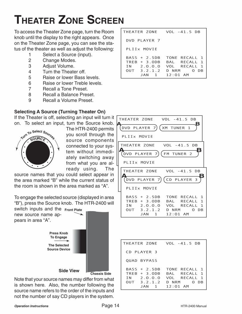
THEATER ZONE SCREENTo access the Theater Zone page, turn the Roomknob until the display to the right appears. Onceon the Theater Zone page, you can see the sta-tus of the theater as well as adjust the following:
1 Select a Source (input).2 Change Modes.3 Adjust Volume.4 Turn the Theater off.5 Raise or lower Bass levels.6 Raise or lower Treble levels.7 Recall a Tone Preset.8 Recall a Balance Preset.9 Recall a Volume Preset.
Selecting A Source (Turning Theater On)If the Theater is off, selecting an input will turn iton. To select an input, turn the Source knob.
The HTR-2400 permitsyou scroll through thesource componentsconnected to your sys-tem without immedi-ately switching awayfrom what you are al-ready using. The
source names that you could select appear inthe area marked “B” while the current status ofthe room is shown in the area marked as “A”.
To engage the selected source (displayed in area“B”), press the Source knob. The HTR-2400 willswitch inputs and thenew source name ap-pears in area “A”.
THEATER ZONE VOL -41.5 DB
DVD PLAYER 7
PLIIx MOVIE
BASS + 2.5DB TONE RECALL 1
TREB + 3.0DB BAL RECALL 1
IN 2.0.0.0 VOL RECALL 1
OUT 3.2.1.2 D NRM 0 DB
JAN 1 12:01 AM
THEATER ZONE VOL -41.5 DB
DVD PLAYER 7 XM TUNER 1
PLIIx MOVIE
BASS + 2.5DB TONE RECALL 1
TREB + 3.0DB BAL RECALL 1
IN 2.0.0.0 VOL RECALL 1
OUT 3.2.1.2 D NRM 0 DB
JAN 1 12:01 AM
A B
THEATER ZONE VOL -41.5 DB
DVD PLAYER 7 FM TUNER 2
PLIIx MOVIE
BASS + 2.5DB TONE RECALL 1
TREB + 3.0DB BAL RECALL 1
IN 2.0.0.0 VOL RECALL 1
OUT 3.2.1.2 D NRM 0 DB
JAN 1 12:01 AM
A B
THEATER ZONE VOL -41.5 DB
DVD PLAYER 7 CD PLAYER 3
PLIIx MOVIE
BASS + 2.5DB TONE RECALL 1
TREB + 3.0DB BAL RECALL 1
IN 2.0.0.0 VOL RECALL 1
OUT 3.2.1.2 D NRM 0 DB
JAN 1 12:01 AM
A B
THEATER ZONE VOL -41.5 DB
CD PLAYER 3
QUAD BYPASS
BASS + 2.5DB TONE RECALL 1
TREB + 3.0DB BAL RECALL 1
IN 2.0.0.0 VOL RECALL 1
OUT 3.2.1.2 D NRM 0 DB
JAN 1 12:01 AM
Note that your source names may differ from whatis shown here. Also, the number following thesource name refers to the order of the inputs andnot the number of say CD players in the system.
SOURCETurn
To Select Sources
HTR-2400 Manual Page 15 Operation Instructions
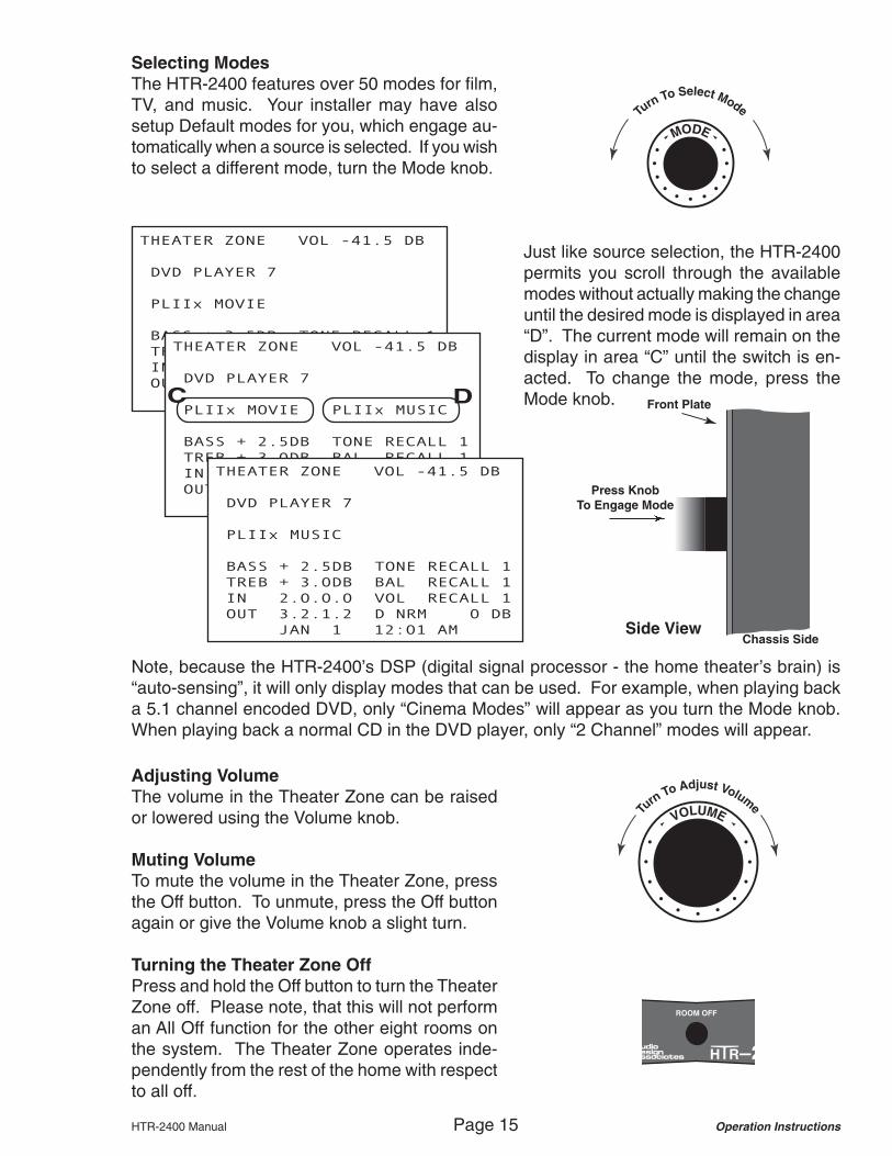
Selecting ModesThe HTR-2400 features over 50 modes for film,TV, and music. Your installer may have alsosetup Default modes for you, which engage au-tomatically when a source is selected. If you wishto select a different mode, turn the Mode knob.
THEATER ZONE VOL -41.5 DB
DVD PLAYER 7
PLIIx MOVIE
BASS + 2.5DB TONE RECALL 1
TREB + 3.0DB BAL RECALL 1
IN 2.0.0.0 VOL RECALL 1
OUT 3.2.1.2 D NRM 0 DB
JAN 1 12:01 AM
Turn To Select Mode
MODE
THEATER ZONE VOL -41.5 DB
DVD PLAYER 7
PLIIx MOVIE PLIIx MUSIC
BASS + 2.5DB TONE RECALL 1
TREB + 3.0DB BAL RECALL 1
IN 2.0.0.0 VOL RECALL 1
OUT 3.2.1.2 D NRM 0 DB
JAN 1 12:01 AM
C D
Side View
Press KnobTo Engage Mode
Chassis Side
Front Plate
THEATER ZONE VOL -41.5 DB
DVD PLAYER 7
PLIIx MUSIC
BASS + 2.5DB TONE RECALL 1
TREB + 3.0DB BAL RECALL 1
IN 2.0.0.0 VOL RECALL 1
OUT 3.2.1.2 D NRM 0 DB
JAN 1 12:01 AM
Just like source selection, the HTR-2400permits you scroll through the availablemodes without actually making the changeuntil the desired mode is displayed in area“D”. The current mode will remain on thedisplay in area “C” until the switch is en-acted. To change the mode, press theMode knob.
Note, because the HTR-2400’s DSP (digital signal processor - the home theater’s brain) is“auto-sensing”, it will only display modes that can be used. For example, when playing backa 5.1 channel encoded DVD, only “Cinema Modes” will appear as you turn the Mode knob.When playing back a normal CD in the DVD player, only “2 Channel” modes will appear.
Adjusting VolumeThe volume in the Theater Zone can be raisedor lowered using the Volume knob.
Muting VolumeTo mute the volume in the Theater Zone, pressthe Off button. To unmute, press the Off buttonagain or give the Volume knob a slight turn.
Turning the Theater Zone OffPress and hold the Off button to turn the TheaterZone off. Please note, that this will not performan All Off function for the other eight rooms onthe system. The Theater Zone operates inde-pendently from the rest of the home with respectto all off.
VOLUMETurn
To Adjust Volume

Operation Instructions Page 16 HTR-2400 Manual
THEATER ZONE SCREEN (cont.)To access the Theater Zone’s other features in-cluding:
Raise or lower Bass levels.Raise or lower Treble levels.Recall a Tone Preset.Recall a Balance Preset.Recall a Volume Preset.
press the Volume knob.
A * (cursor) will begin flashing on the first fea-ture, BASS.
VOLUMETurn
To Adjust Volume
Side View
Press KnobTo Advance
To The NextFeature
Chassis Side
Front Plate
THEATER ZONE VOL -41.5 DB
DVD PLAYER 7
PLIIx MOVIE
* BASS + 3.0DB TONE RECALL 1
TREB + 3.0DB BAL RECALL 1
IN 2.0.0.0 VOL RECALL 1
OUT 3.2.1.2 D NRM 0 DB
JAN 1 12:01 AM
The HTR-2400’s out of the box settingshave all speakers not including thesubwoofer operate with these bass andtreble control options. However, your cus-tom installer may have modified your sys-tems operation such that these featuresdo operate in this manner. ADA recom-mends consulting with your custom installprofessional to determine if these featuresshould be used.
Bass AdjustmentWhile the * (cursor) is on BASS, turningthe Volume knob will raise or lower thebass level.
To advance to the next feature, press theVolume knob.
Treble AdjustmentWhile the * (cursor) is on TREB, turningthe Volume knob will raise or lower thetreble level.
To advance to the next feature, press theVolume knob.
THEATER ZONE VOL -41.5 DB
DVD PLAYER 7
PLIIx MOVIE
* BASS + 3.5DB TONE RECALL 1
TREB + 3.0DB BAL RECALL 1
IN 2.0.0.0 VOL RECALL 1
OUT 3.2.1.2 D NRM 0 DB
JAN 1 12:01 AMTHEATER ZONE VOL -41.5 DB
DVD PLAYER 7
PLIIx MOVIE
* BASS + 4.0DB TONE RECALL 1
TREB + 3.0DB BAL RECALL 1
IN 2.0.0.0 VOL RECALL 1
OUT 3.2.1.2 D NRM 0 DB
JAN 1 12:01 AM
THEATER ZONE VOL -41.5 DB
DVD PLAYER 7
PLIIx MOVIE
BASS + 4.0DB TONE RECALL 1
*TREB + 3.0DB BAL RECALL 1
IN 2.0.0.0 VOL RECALL 1
OUT 3.2.1.2 D NRM 0 DB
JAN 1 12:01 AM

HTR-2400 Manual Page 17 Operation Instructions
Recalling a PresetThe HTR-2400 features three types of presets (Tones, Balance, and Volume). Each type ofpreset has four options numbered accordingly. For you to be able to recall a preset, it mustfirst be created. ADA recommends contacting your installation professional to see if presetsare programmed into your system.
Exiting (regain use of the Volume knob)To exit this feature:a Press the Volume knob repeatedly until
the * has scrolled through TREB,TONE RECALL, BAL RECALL andVOL RECALL or...
b Turn the Room knob to changescreens or...
c Let the screen time out (30 seconds).
THEATER ZONE VOL -41.5 DB
DVD PLAYER 7
PLIIx MOVIE
BASS + 4.0DB * TONE RECALL 1
TREB + 3.0DB BAL RECALL 1
IN 2.0.0.0 VOL RECALL 1
OUT 3.2.1.2 D NRM 0 DB
JAN 1 12:01 AM
THEATER ZONE VOL -41.5 DB
DVD PLAYER 7
PLIIx MOVIE
BASS + 4.0DB * T RECALLED 2
TREB + 3.0DB BAL RECALL 1
IN 2.0.0.0 VOL RECALL 1
OUT 3.2.1.2 D NRM 0 DB
JAN 1 12:01 AM
Tone PresetsThe Theater Zone has four Tone Presets. Thisis actually a complex feature set of the HTR-2400. Tone Presets permit the installer to cre-ate two groups of speakers (A and B). Eachgrouping can have an independent bass fre-quency point, bass level, treble frequency point,and treble level. These features are used forroom equalization.
To recall a Tone Preset, press the Volume knobso that the flashing * (cursor) is on TONE RE-CALL #. Turning the Volume knob will allow youto select one of the four Tone Presets. Presetrecall is immediate and will occur a second afterthe tone preset number is displayed.
Balance PresetsBalance presets contain both levels and delaysettings of all speakers in your theater. This per-mits your installer to optimize the sound in thetheater for multiple seating positions (hot spots).Please note, that in order for this feature to work,you must have stored Balance Presets.
To recall a Balance Preset, press the Volumeknob so that the flashing * (cursor) is on BALRECALL #. Then turn the Volume knob until thedesired preset number is displayed. Preset re-call is immediate and will occur a second afterthe balance preset number is displayed.
Volume PresetsVolume presets contain the master volume levelof the theater. Your custom installation profes-sional will have had to store these presets if youwish to use this feature as intended. There arefour Volume Presets permitting you to perhapsset up a low, medium, high and super demo level.
To recall a preset, press the Volume knob untilthe * is flashing on VOL RECALL. Then turn theVolume knob to select the preset number. Pre-set recall is immediate and will occur a secondafter the balance preset number is displayed.
THEATER ZONE VOL -41.5 DB
DVD PLAYER 7
PLIIx MOVIE
BASS + 4.0DB T RECALLED 2
TREB + 3.0DB *BAL RECALL 1
IN 2.0.0.0 VOL RECALL 1
OUT 3.2.1.2 D NRM 0 DB
JAN 1 12:01 AM
THEATER ZONE VOL -41.5 DB
DVD PLAYER 7
PLIIx MOVIE
BASS + 4.0DB T RECALLED 2
TREB + 3.0DB BAL RECALL 1
IN 2.0.0.0 *VOL RECALL 1
OUT 3.2.1.2 D NRM 0 DB
JAN 1 12:01 AM

Operation Instructions Page 18 HTR-2400 Manual
ALL ROOMS SCREEN
*THEATER ZONE THEATER OFF
ROOM 1 ROOM OFF
ROOM 2 ROOM OFF
ROOM 3 ROOM OFF
ROOM 4 ROOM OFF
ROOM 5 ROOM OFF
ROOM 6 ROOM OFF
ROOM 7 ROOM OFF
ROOM 8 ROOM OFF
JAN 1 12:01 AM
THEATER ZONE THEATER OFF
* ROOM 1 ROOM OFF
ROOM 2 ROOM OFF
ROOM 3 ROOM OFF
ROOM 4 ROOM OFF
ROOM 5 ROOM OFF
ROOM 6 ROOM OFF
ROOM 7 ROOM OFF
ROOM 8 ROOM OFF
JAN 1 12:01 AM
THEATER ZONE THEATER OFF
ROOM 1 ROOM OFF
* ROOM 2 ROOM OFF
ROOM 3 ROOM OFF
ROOM 4 ROOM OFF
ROOM 5 ROOM OFF
ROOM 6 ROOM OFF
ROOM 7 ROOM OFF
ROOM 8 ROOM OFF
JAN 1 12:01 AM
THEATER ZONE THEATER OFF
ROOM 1 ROOM OFF
ROOM 2 ROOM OFF
* ROOM 3 ROOM OFF
ROOM 4 ROOM OFF
ROOM 5 ROOM OFF
ROOM 6 ROOM OFF
ROOM 7 ROOM OFF
ROOM 8 ROOM OFF
JAN 1 12:01 AM
Side View
Press KnobTo Advance
Chassis Side
Front Plate
*THEATER ZONE THEATER OFF
ROOM 1 ROOM OFF
ROOM 2 ROOM OFF
ROOM 3 ROOM OFF
ROOM 4 ROOM OFF
ROOM 5 ROOM OFF
ROOM 6 ROOM OFF
ROOM 7 ROOM OFF
ROOM 8 ROOM OFF
JAN 1 12:01 AM
To access the All Rooms page, turn the Roomknob until the display to the right appears. Pleasenote, that since the HTR-2400 can have the roomnames customized, your display may read slightlydifferent.
Once on the All Rooms page, you can see whatrooms/zones are off as well as rooms that are onand what source is playing to it.
On this page you can:1 Select a room.2 Select a source to the room.3 Turn the room off.4 Adjust room volume (the display
will not indicate volume levels).
To select a room you wish to control, repeatedlypress the Room knob. The * (cursor) will ad-vance downward to the next room with eachpress of the Room knob.
When you reach the last room, the next press ofthe Room button will advance the * (cursor) tothe Theater Zone (top line).
If you turn the Room knob, the display will ad-vance to other screens. When you return to theAll Rooms page, the * (cursor) will appear nextto the last selected room name.

HTR-2400 Manual Page 19 Operation Instructions
Side View
Press KnobTo Engage
The SelectedSource Device
Chassis Side
Front Plate
THEATER ZONE DVD PLAYER
*ROOM 1 >TUNER 1
ROOM 2 ROOM OFF
ROOM 3 ROOM OFF
ROOM 4 ROOM OFF
ROOM 5 ROOM OFF
ROOM 6 ROOM OFF
ROOM 7 ROOM OFF
ROOM 8 ROOM OFF
JAN 1 12:01 AM
*THEATER ZONE THEATER OFF
ROOM 1 ROOM OFF
ROOM 2 ROOM OFF
ROOM 3 ROOM OFF
ROOM 4 ROOM OFF
ROOM 5 ROOM OFF
ROOM 6 ROOM OFF
ROOM 7 ROOM OFF
ROOM 8 ROOM OFF
JAN 1 12:01 AM
SOURCETurn
To Select Sources
*THEATER ZONE >DVD PLAYER 1
ROOM 1 ROOM OFF
ROOM 2 ROOM OFF
ROOM 3 ROOM OFF
ROOM 4 ROOM OFF
ROOM 5 ROOM OFF
ROOM 6 ROOM OFF
ROOM 7 ROOM OFF
ROOM 8 ROOM OFF
JAN 1 12:01 AM
*THEATER ZONE >DSS 2
ROOM 1 ROOM OFF
ROOM 2 ROOM OFF
ROOM 3 ROOM OFF
ROOM 4 ROOM OFF
ROOM 5 ROOM OFF
ROOM 6 ROOM OFF
ROOM 7 ROOM OFF
ROOM 8 ROOM OFF
JAN 1 12:01 AM
*THEATER ZONE DSS 2
ROOM 1 ROOM OFF
ROOM 2 ROOM OFF
ROOM 3 ROOM OFF
ROOM 4 ROOM OFF
ROOM 5 ROOM OFF
ROOM 6 ROOM OFF
ROOM 7 ROOM OFF
ROOM 8 ROOM OFF
JAN 1 12:01 AM
While the * (cursor) is set to theTheater Zone, turning the Sourceknob will scroll through only thesources available in the home the-ater. Please note, these may dif-fer from the sources accessible inthe other rooms/zones.
Once the desiredsource is dis-played, pressingof the Sourceknob will engagethat component.If the theater wasoff, this functionwill also turn theTheater on.
To select sources for additionalrooms, press the Room knob toadvance the * (cursor) to the de-sired room. Then, using theSource knob, dial in the desiredsource component. Once it isdisplayed, press the Sourceknob to engage the selection.Please note, that sources usedin the eight house-wide rooms,may differ from the sources avail-able in the Theater Zone.
THEATER ZONE DVD PLAYER
*ROOM 1 >TUNER 2
ROOM 2 ROOM OFF
ROOM 3 ROOM OFF
ROOM 4 ROOM OFF
ROOM 5 ROOM OFF
ROOM 6 ROOM OFF
ROOM 7 ROOM OFF
ROOM 8 ROOM OFF
JAN 1 12:01 AM
THEATER ZONE DVD PLAYER
*ROOM 1 TUNER 2
ROOM 2 ROOM OFF
ROOM 3 ROOM OFF
ROOM 4 ROOM OFF
ROOM 5 ROOM OFF
ROOM 6 ROOM OFF
ROOM 7 ROOM OFF
ROOM 8 ROOM OFF
JAN 1 12:01 AM*THEATER ZONE DSS 2
ROOM 1 ROOM OFF
ROOM 2 ROOM OFF
ROOM 3 ROOM OFF
ROOM 4 ROOM OFF
ROOM 5 ROOM OFF
ROOM 6 ROOM OFF
ROOM 7 ROOM OFF
ROOM 8 ROOM OFF
JAN 1 12:01 AM
To turn off a room, press the Roomknob so that the * (cursor) is nextto the room name or number.Then press the Off button situatedbetween the knobs. To turn off allrooms, press and hold the Off but-ton. The Theater Zone needs tobe turned off seperately.
Operation Instructions Page 20 HTR-2400 Manual
ROOM 1 VOLUME 36
TUNER 2 95.5 FM
BASS + 6 BALANCE EQUAL
MID + 4 LOUDNESS ON
TREB + 7 LIMITER ON
TONE 1
JAN 1 12:01 AM
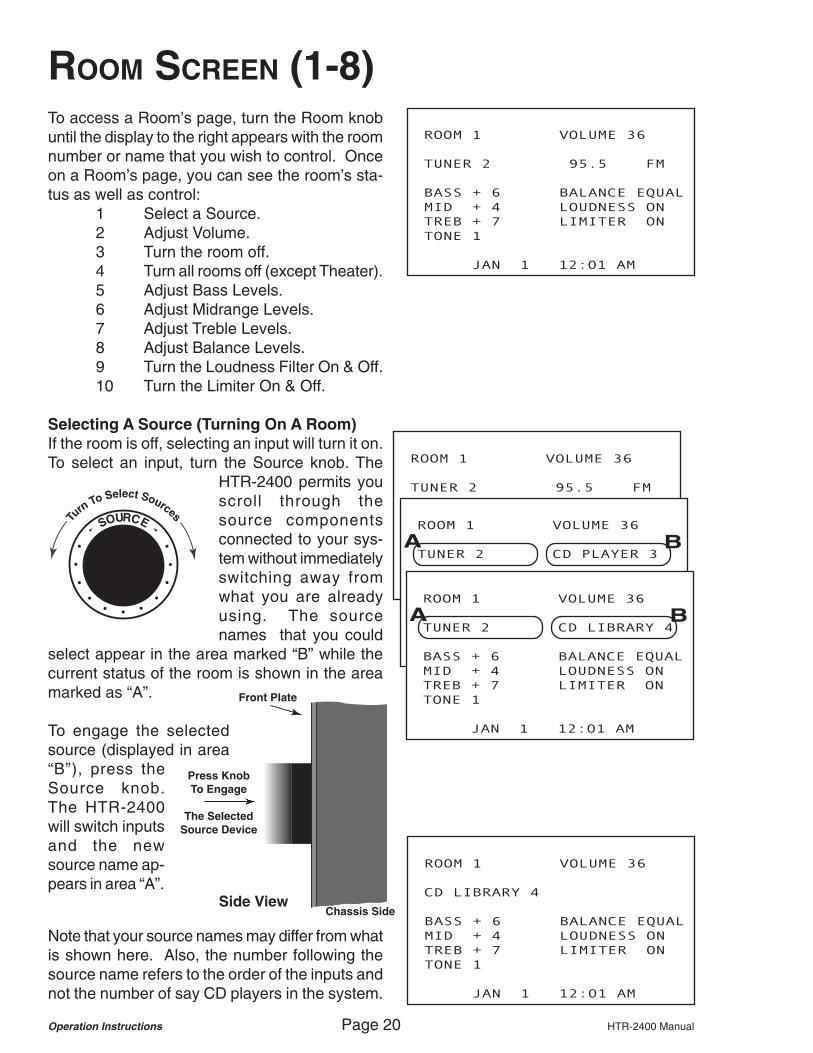
ROOM SCREEN (1-8)To access a Room’s page, turn the Room knobuntil the display to the right appears with the roomnumber or name that you wish to control. Onceon a Room’s page, you can see the room’s sta-tus as well as control:
1 Select a Source.2 Adjust Volume.3 Turn the room off.4 Turn all rooms off (except Theater).5 Adjust Bass Levels.6 Adjust Midrange Levels.7 Adjust Treble Levels.8 Adjust Balance Levels.9 Turn the Loudness Filter On & Off.10 Turn the Limiter On & Off.
Selecting A Source (Turning On A Room)If the room is off, selecting an input will turn it on.To select an input, turn the Source knob. The
HTR-2400 permits youscroll through thesource componentsconnected to your sys-tem without immediatelyswitching away fromwhat you are alreadyusing. The sourcenames that you could
select appear in the area marked “B” while thecurrent status of the room is shown in the areamarked as “A”.
To engage the selectedsource (displayed in area“B”), press theSource knob.The HTR-2400will switch inputsand the newsource name ap-pears in area “A”.
ROOM 1 VOLUME 36
TUNER 2 95.5 FM
BASS + 6 BALANCE EQUAL
MID + 4 LOUDNESS ON
TREB + 7 LIMITER ON
TONE 1
JAN 1 12:01 AM
Side View
Press KnobTo Engage
The SelectedSource Device
Chassis Side
Front Plate
SOURCETurn
To Select Sources
Note that your source names may differ from whatis shown here. Also, the number following thesource name refers to the order of the inputs andnot the number of say CD players in the system.
ROOM 1 VOLUME 36
TUNER 2 CD PLAYER 3
BASS + 6 BALANCE EQUAL
MID + 4 LOUDNESS ON
TREB + 7 LIMITER ON
TONE 1
JAN 1 12:01 AM
A B
ROOM 1 VOLUME 36
TUNER 2 CD LIBRARY 4
BASS + 6 BALANCE EQUAL
MID + 4 LOUDNESS ON
TREB + 7 LIMITER ON
TONE 1
JAN 1 12:01 AM
A B
ROOM 1 VOLUME 36
CD LIBRARY 4
BASS + 6 BALANCE EQUAL
MID + 4 LOUDNESS ON
TREB + 7 LIMITER ON
TONE 1
JAN 1 12:01 AM

HTR-2400 Manual Page 21 Operation Instructions
ROOM 1 VOLUME 36
TUNER 2 95.5 FM
*BASS + 6 BALANCE EQUAL
MID + 4 LOUDNESS ON
TREB + 7 LIMITER ON
TONE 1
JAN 1 12:01 AM
ROOM 1 VOLUME 36
*ROOM OFF
BASS + 6 BALANCE EQUAL
MID + 4 LOUDNESS ON
TREB + 7 LIMITER ON
TONE 1
JAN 1 12:01 AM
Adjusting VolumeThe volume can be raised or lowered using theVolume knob.
Turning Off A Room or All RoomsYou can quickly turn off a roomby simply pressing the RoomOff button. If other rooms areon (other than the TheaterZone), the display will read ROOM OFF. To turnoff all rooms (other than the Theater Zone), pressand hold the Room Off button.
The Theater Zone must be turned off seperatelyand does not turn off with the multi-room’s All Offcommand.
Adjusting Bass, Midrange & TrebleTo access the controls for bass, midrange, treble,tone preset recalls, balance control, loudness fil-ter and limiter, press the Volume knob.
VOLUMETurn
To Adjust Volume
ROOM 1 VOLUME 36
ALL OFF
BASS + 6 BALANCE EQUAL
MID + 4 LOUDNESS ON
TREB + 7 LIMITER ON
TONE 1
JAN 1 12:01 AM
VOLUMETurn
To Adjust Volume
Side View
Press KnobTo Advance
To The NextFeature
Chassis Side
Front Plate
ROOM 1 VOLUME 36
TUNER 2 95.5 FM
BASS + 6 BALANCE EQUAL
*MID + 4 LOUDNESS ON
TREB + 7 LIMITER ON
TONE 1
JAN 1 12:01 AM
ROOM 1 VOLUME 36
TUNER 2 95.5 FM
BASS + 6 BALANCE EQUAL
MID + 4 LOUDNESS ON
*TREB + 7 LIMITER ON
TONE 1
JAN 1 12:01 AM
A * (cursor) will begin flashing next to thefirst feature, BASS. Use the Volume knobto raise or lower bass levels.
To advance to the next feature, press theVolume knob. The * (cursor) will indicatethe next feature. Again, use the Volumeknob to adjust this feature.

Operation Instructions Page 22 HTR-2400 Manual
ROOM 1 VOLUME 36
TUNER 2 95.5 FM
BASS + 6 BALANCE EQUAL
MID + 4 LOUDNESS ON
TREB + 7 LIMITER ON
*TONE 1
JAN 1 12:01 AM
ROOM SCREEN (CONT.)Tone Preset RecallThe HTR-2400 features four tone presets perroom. These presets store tone levels and Loud-ness & Limiter filter settings and can be recalledalong with a fifth preset, Flat. If Flat is selected,all levels (other than Balance) are set to 0 andthe Loudness Filter and Limiter are turned off.
In order for Presets 1 through 4 to operate, yourcustom installation professional will have neededto program the presets.
To recall a Tone Preset, press the Volume Knobuntil the flashing * is on TONE. Turn the Volumeknob to the desired preset number (1-4) or theletter “F” (for Flat). The recalling of the preset isimmediate and no other action is required.
Balance AdjustmentBalance allows you to compensate speaker lev-els to either the right or left speaker(s). To adjustbalance, press the Volume knob so that the * ison BALANCE. Then turn the Volume knob tomove the balance level to the left or to the right.
Loudness Contour Filter (On or Off)Loudness contour is an active filter that enhancesbass levels particularly at low volume levels. Asthe rooms volume is increased the effect of thisfilter is minimized. This permits the HTR-2400to sound great even at background listening lev-els. To turn Loudness on or off, press the Vol-ume knob so that the * is on LOUDNESS andturn the Volume knob.
LimiterThe HTR-2400 features a digital limiter whichprevents clipping. To turn this feature on or off,press the Volume knob until the * is on LIMITERand then turn the Volume knob to turn this fea-ture on or off.
Exiting (regain use of the Volume knob)a Press the Volume knob repeatedly until the *
has scrolled through all features or...b Turn the Room knob to change screens or...c Let the screen time out (30 seconds).
ROOM 1 VOLUME 36
TUNER 2 95.5 FM
BASS + 1 BALANCE EQUAL
MID + 7 LOUDNESS ON
TREB + 3 LIMITER OFF
*TONE 2
JAN 1 12:01 AM
ROOM 1 VOLUME 36
TUNER 2 95.5 FM
BASS + 1 *BALANCE R 3
MID + 7 LOUDNESS ON
TREB + 3 LIMITER OFF
TONE 2
JAN 1 12:01 AM
ROOM 1 VOLUME 36
TUNER 2 95.5 FM
BASS + 1 BALANCE R 3
MID + 7 *LOUDNESS ON
TREB + 3 LIMITER OFF
TONE 2
JAN 1 12:01 AM
ROOM 1 VOLUME 36
TUNER 2 95.5 FM
BASS + 1 BALANCE R 3
MID + 7 LOUDNESS ON
TREB + 3 *LIMITER OFF
TONE 2
JAN 1 12:01 AM

HTR-2400 Manual Page 23 Operation Instructions
PARTYGROUP 1 XM TUNER 1
*ROOM 1 ROOM 5
*ROOM 2 ROOM 6
*ROOM 3 *ROOM 7
ROOM 4 ROOM 8
JAN 1 12:01 AM
PARTY GROUP SCREEN
Side View
Press KnobTo Engage
The SelectedSource Device
Chassis Side
Front Plate
SOURCETurn
To Select Sources
Turn
To Select Screen
ROOM
Side View
Press KnobTo Advance
Through The4 Party Groups
Chassis Side
Front Plate
To access Party Group control, turn the roomknob until the screen shows the Party Grouppage.
In order for this feature to operate, yourinstallation professional must have alreadyassigned rooms to one (or more) of thefour available Party Groups. A * will ap-pear next to rooms that are assigned tothe Party Group. To advance through allfour Party Groups, repeatedly press theRoom knob.
PARTYGROUP 2 XM TUNER 1
*ROOM 1 *ROOM 5
ROOM 2 *ROOM 6
ROOM 3 *ROOM 7
*ROOM 4 ROOM 8
JAN 1 12:01 AM
PARTYGROUP 3 XM TUNER 1
ROOM 1 *ROOM 5
ROOM 2 *ROOM 6
ROOM 3 ROOM 7
ROOM 4 *ROOM 8
JAN 1 12:01 AM PARTYGROUP 4 XM TUNER 1
*ROOM 1 *ROOM 5
*ROOM 2 *ROOM 6
*ROOM 3 *ROOM 7
*ROOM 4 *ROOM 8
JAN 1 12:01 AM
PARTYGROUP 4 > FM TUNER 2
*ROOM 1 *ROOM 5
*ROOM 2 *ROOM 6
*ROOM 3 *ROOM 7
*ROOM 4 *ROOM 8
JAN 1 12:01 AM
PARTYGROUP 4 > CD PLAYER 3
*ROOM 1 *ROOM 5
*ROOM 2 *ROOM 6
*ROOM 3 *ROOM 7
*ROOM 4 *ROOM 8
JAN 1 12:01 AM
PARTYGROUP 4 CD PLAYER 3
*ROOM 1 *ROOM 5
*ROOM 2 *ROOM 6
*ROOM 3 *ROOM 7
*ROOM 4 *ROOM 8
JAN 1 12:01 AM
To select a source for a Party Group, turnthe Source knob until the desired compo-nent is displayed.
Then press the Sourceknob to engage that in-put to the rooms in theParty Group.

Multi-Room Setup Page 24 HTR-2400 Manual
ENTERING SETUP MODE
SETUP M
|
ENTER CODE XXXX
BUTTON/ENCODER TEST
SETUP M
|
ENTER CODE 1XXX
BUTTON/ENCODER TEST
SETUP M
|
ENTER CODE 18XX
BUTTON/ENCODER TEST SETUP M
|
ENTER CODE 186X
BUTTON/ENCODER TEST SETUP M
|
ENTER CODE 1867
BUTTON/ENCODER TEST
MAIN SETUP MENU M
> HOME THEATER
PARTY TONE
INPUT TRIMS LABELS/SOURCE
ADA BUS AC POWER
VOLUME VERSION
BALANCE CLOCK SET
FACTORY DEFAULT
MODE
Side View
Press & HoldKnob To Enter
SetupFeature
Chassis Side
Front Plate
The code to enter the HTR-2400’s setup menuis 1867. To enter the setup section of the HTR-2400, press and hold the Mode knob for 5 sec-onds until the display reads:
VOLUMEUseTo Dial Code 1867 Turn the Volume knob
until the first X is re-placed by the number1 in the code 1867.
Advance Cursor
MODE
Turn the Mode knob to ad-vance the cursor to the nextposition. Again use theVolume knob to dial in thenumber 8. Repeat this un-til the code 1867 is dis-played.
MODE
When the code 1867 is displayed,press and release the Mode knob.
HTR-2400 Manual Page 25 Multi-Room Setup
MAIN SETUP MENU M
> HOME THEATER
PARTY TONE
INPUT TRIMS LABELS/SOURCE
ADA BUS AC POWER
VOLUME VERSION
BALANCE CLOCK SET
FACTORY DEFAULT
NAVIGATING SETUP MODEMODE
VOLUME
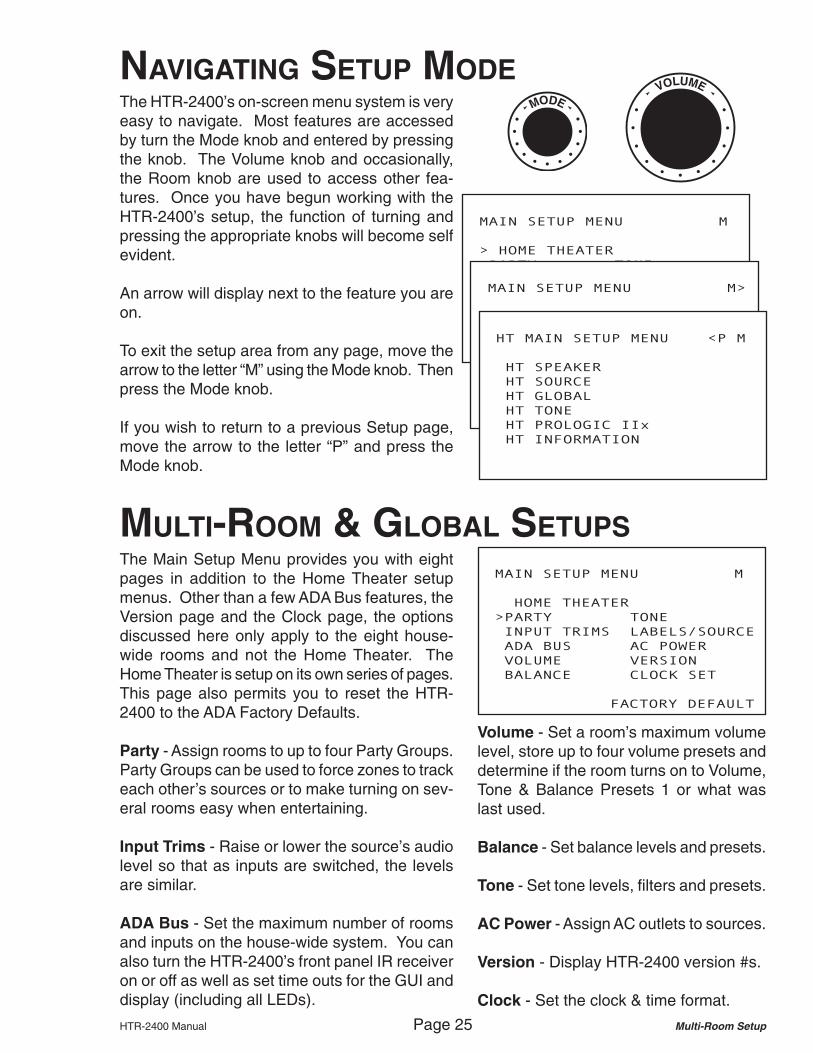
The HTR-2400’s on-screen menu system is veryeasy to navigate. Most features are accessedby turn the Mode knob and entered by pressingthe knob. The Volume knob and occasionally,the Room knob are used to access other fea-tures. Once you have begun working with theHTR-2400’s setup, the function of turning andpressing the appropriate knobs will become selfevident.
An arrow will display next to the feature you areon.
To exit the setup area from any page, move thearrow to the letter “M” using the Mode knob. Thenpress the Mode knob.
If you wish to return to a previous Setup page,move the arrow to the letter “P” and press theMode knob.
MAIN SETUP MENU M>
HOME THEATER
PARTY TONE
INPUT TRIMS LABELS/SOURCE
ADA BUS AC POWER
VOLUME VERSION
BALANCE CLOCK SET
FACTORY DEFAULT
HT MAIN SETUP MENU <P M
HT SPEAKER
HT SOURCE
HT GLOBAL
HT TONE
HT PROLOGIC IIx
HT INFORMATION
MULTI-ROOM & GLOBAL SETUPS
MAIN SETUP MENU M
HOME THEATER
>PARTY TONE
INPUT TRIMS LABELS/SOURCE
ADA BUS AC POWER
VOLUME VERSION
BALANCE CLOCK SET
FACTORY DEFAULT
The Main Setup Menu provides you with eightpages in addition to the Home Theater setupmenus. Other than a few ADA Bus features, theVersion page and the Clock page, the optionsdiscussed here only apply to the eight house-wide rooms and not the Home Theater. TheHome Theater is setup on its own series of pages.This page also permits you to reset the HTR-2400 to the ADA Factory Defaults.
Party - Assign rooms to up to four Party Groups.Party Groups can be used to force zones to trackeach other’s sources or to make turning on sev-eral rooms easy when entertaining.
Input Trims - Raise or lower the source’s audiolevel so that as inputs are switched, the levelsare similar.
ADA Bus - Set the maximum number of roomsand inputs on the house-wide system. You canalso turn the HTR-2400’s front panel IR receiveron or off as well as set time outs for the GUI anddisplay (including all LEDs).
Volume - Set a room’s maximum volumelevel, store up to four volume presets anddetermine if the room turns on to Volume,Tone & Balance Presets 1 or what waslast used.
Balance - Set balance levels and presets.
Tone - Set tone levels, filters and presets.
AC Power - Assign AC outlets to sources.
Version - Display HTR-2400 version #s.
Clock - Set the clock & time format.

Multi-Room Setup Page 26 HTR-2400 Manual
INPUT TRIM SETUPThe adjustment of Input Trim levels is a featurethat helps maintain even volume levels whenswitching between sources. The Mode knob ad-vances through Source Names. The arrow willindicate which source you are on.
Turn To Select Input
MODE
INPUT TRIM SETUP P M
XM TUNER = -3dB
>FM TUNER = +2dB
CD PLAYER = 0dB
CD LIBRARY = 0dB
SATELLITE = 0dB
CABLE BOX = 0dB
DVD PLAYER = 0dB
AUXILIARY = 0dB
INPUT TRIM SETUP P M
>XM TUNER = -3dB
FM TUNER = 0dB
CD PLAYER = 0dB
CD LIBRARY = 0dB
SATELLITE = 0dB
CABLE BOX = 0dB
DVD PLAYER = 0dB
AUXILIARY = 0dB
MAIN SETUP MENU M
HOME THEATER
PARTY TONE
>INPUT TRIMS LABELS/SOURCE
ADA BUS AC POWER
VOLUME VERSION
BALANCE CLOCK SET
FACTORY DEFAULT
VOLUMERaise or Lower Trims
The Volume knob is used to raise or lowerInput Trim levels for each source.
PARTY MODE SETUP
MAIN SETUP MENU M
HOME THEATER
>PARTY TONE
INPUT TRIMS LABELS/SOURCE
ADA BUS AC POWER
VOLUME VERSION
BALANCE CLOCK SET
FACTORY DEFAULT
PARTY SETUP P M
|
PARTY 1 2 3 4
ROOM 1 * *
ROOM 2 *
ROOM 3
>ROOM 4 * *
ROOM 5
ROOM 6
ROOM 7
ROOM 8
PARTY SETUP P M
|
PARTY 1 2 3 4
ROOM 1 * *
ROOM 2 *
ROOM 3
ROOM 4 * *
ROOM 5
>ROOM 6 *
ROOM 7
ROOM 8
Turn
To Select Room
#
MODE
Select Party Group
ROOM
VOLUMEParty Off Party On
Party Mode permits you tohave rooms track a specificParty Group number. Usethe Mode knob to advancethrough room numbers/names. The arrow will pointto the room selected.
The Room knob is used toselect the Party Group youwish to edit. Turning theroom knob will advance thearrow over the Party Groupnumber.
The Volume knob is used tomake a room part of a PartyGroup. Rotating it clock-wise turns Party On. A *(star) indicates that Party isOn. Turning it counter-clockwise turns Party Off.
HTR-2400 Manual Page 27 Multi-Room Setup
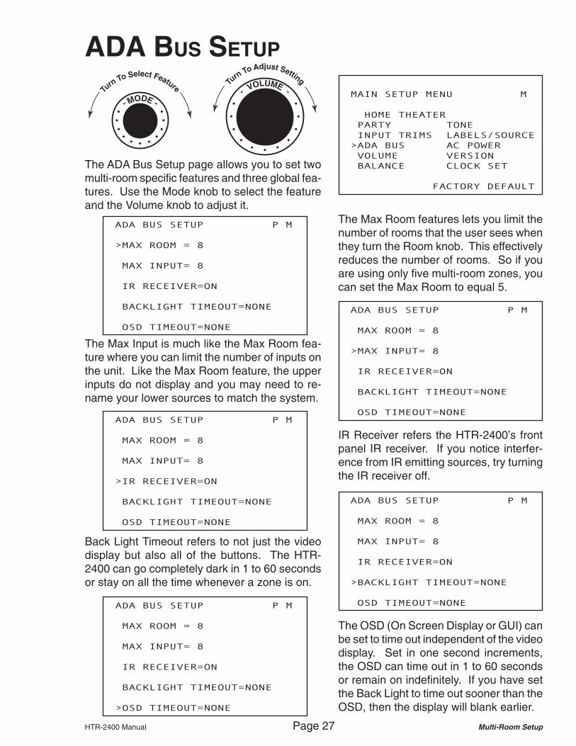
ADA BUS SETUP P M
MAX ROOM = 8
>MAX INPUT= 8
IR RECEIVER=ON
BACKLIGHT TIMEOUT=NONE
OSD TIMEOUT=NONE
ADA BUS SETUP P M
MAX ROOM = 8
MAX INPUT= 8
IR RECEIVER=ON
BACKLIGHT TIMEOUT=NONE
>OSD TIMEOUT=NONE
Turn
To Select Feature
MODE
MAIN SETUP MENU M
HOME THEATER
PARTY TONE
INPUT TRIMS LABELS/SOURCE
>ADA BUS AC POWER
VOLUME VERSION
BALANCE CLOCK SET
FACTORY DEFAULT
ADA BUS SETUP P M
MAX ROOM = 8
MAX INPUT= 8
>IR RECEIVER=ON
BACKLIGHT TIMEOUT=NONE
OSD TIMEOUT=NONE
ADA BUS SETUP P M
MAX ROOM = 8
MAX INPUT= 8
IR RECEIVER=ON
>BACKLIGHT TIMEOUT=NONE
OSD TIMEOUT=NONE
ADA BUS SETUP P M
>MAX ROOM = 8
MAX INPUT= 8
IR RECEIVER=ON
BACKLIGHT TIMEOUT=NONE
OSD TIMEOUT=NONE
VOLUMETurn
To Adjust Setting
ADA BUS SETUP
The ADA Bus Setup page allows you to set twomulti-room specific features and three global fea-tures. Use the Mode knob to select the featureand the Volume knob to adjust it.
The Max Room features lets you limit thenumber of rooms that the user sees whenthey turn the Room knob. This effectivelyreduces the number of rooms. So if youare using only five multi-room zones, youcan set the Max Room to equal 5.
The Max Input is much like the Max Room fea-ture where you can limit the number of inputs onthe unit. Like the Max Room feature, the upperinputs do not display and you may need to re-name your lower sources to match the system.
IR Receiver refers the HTR-2400’s frontpanel IR receiver. If you notice interfer-ence from IR emitting sources, try turningthe IR receiver off.
Back Light Timeout refers to not just the videodisplay but also all of the buttons. The HTR-2400 can go completely dark in 1 to 60 secondsor stay on all the time whenever a zone is on.
The OSD (On Screen Display or GUI) canbe set to time out independent of the videodisplay. Set in one second increments,the OSD can time out in 1 to 60 secondsor remain on indefinitely. If you have setthe Back Light to time out sooner than theOSD, then the display will blank earlier.

Multi-Room Setup Page 28 HTR-2400 Manual
Turn
To Select Feature
MODE
VOLUMETurn
To Adjust Setting
VOLUME SETUP
VOLUME SETUP P M
ROOM 3
VOLUME=53 VOLUME MAX=65
>TURN ON WITH RECALL 1
STORE 1 RECALL 1
STORE 2 RECALL 2
STORE 3 RECALL 3
STORE 4 RECALL 4
VOLUME SETUP P M
ROOM 3
VOLUME=53 >VOLUME MAX=65
TURN ON WITH LAST USED
STORE 1 RECALL 1
STORE 2 RECALL 2
STORE 3 RECALL 3
STORE 4 RECALL 4
VOLUME SETUP P M
ROOM 3
>VOLUME=53 VOLUME MAX=80
TURN ON WITH LAST USED
STORE 1 RECALL 1
STORE 2 RECALL 2
STORE 3 RECALL 3
STORE 4 RECALL 4
VOLUME SETUP P M
>ROOM 1
VOLUME=45 VOLUME MAX=80
TURN ON WITH LAST USED
STORE 1 RECALL 1
STORE 2 RECALL 2
STORE 3 RECALL 3
STORE 4 RECALL 4
MAIN SETUP MENU M
HOME THEATER
PARTY TONE
INPUT TRIMS LABELS/SOURCE
ADA BUS AC POWER
>VOLUME VERSION
BALANCE CLOCK SET
FACTORY DEFAULT
On the Volume Setup page, one can set volumeparameters for all eight rooms of the whole-housesystem. This includes setting a room’s maximumvolume level, storing volume presets, and select-ing if a room turns on to the last acoustical set-tings used in that room or to all presets stored onPreset 1 (including Volume, Tones, and BalancePresets 1).
When the arrow is on theroom name/number, turn-ing the Volume knob per-mits you to cycle throughthe eight rooms on thesystem.
Once the desired room isselected, turning theMode knob advances thearrow to the next feature.
VOLUME SETUP P M
>ROOM 3
VOLUME=45 VOLUME MAX=80
TURN ON WITH LAST USED
STORE 1 RECALL 1
STORE 2 RECALL 2
STORE 3 RECALL 3
STORE 4 RECALL 4
When on Volume, you can alter a roomsvolume level. This is useful for setting upthe four Volume Presets. Alternately, youcould also adjust the room’s volume levelfrom its keypad or control.
Volume Preset 1 can be used as the turnon preset volume level.
Turn the Mode knob to advance to the next fea-ture, Volume Max, which refers to the maximumvolume level the room can reach. This feature isuseful to prevent a room from either distorting orplaying louder than intended. Use the Volumeknob to adjust the room’s maximum volume level.
Turn the Mode knob to advance to the next fea-ture, Turn On With, which determines if the roomwill turn on to its last acoustical settings used orturn on to a preset acoustical setting. The pre-set number recalled involves all Preset 1 func-tions, including Volume, Tones, and Balance. Assuch, this feature is ideal for starting at the per-fect acoustical level each and every time the roomis turned on. To alter between Last Used or Pre-set Recall number 1, turn the Volume knob.

HTR-2400 Manual Page 29 Multi-Room Setup
VOLUME SETUP P M
ROOM 3
VOLUME=53 VOLUME MAX=65
TURN ON WITH RECALL 1
STORE 1 RECALL 1
STORE 2 >RECALL 2
STORE 3 RECALL 3
STORE 4 RECALL 4
VOLUME SETUP P M
ROOM 3
VOLUME=53 VOLUME MAX=65
TURN ON WITH RECALL 1
>STORE 1 RECALL 1
STORE 2 RECALL 2
STORE 3 RECALL 3
STORE 4 RECALL 4
MODE
Press Mode To Recall
MODE
Press Mode To Store
VOLUME SETUP P M
ROOM 3
VOLUME=53 VOLUME MAX=65
TURN ON WITH RECALL 1
> OK 1 RECALL 1
STORE 2 RECALL 2
STORE 3 RECALL 3
STORE 4 RECALL 4
Storing Volume Presets first requires that thedesired volume level is displayed. Once the cor-rect volume level has been dialed in, turn theMode knob to advance the arrow to the presetyou wish to store (STORE 1 - 4).
Then press the Mode knob toStore the preset. The display willmomentarily display the wordOK and then return to showingthe word STORE #.
Again, Volume Preset 1 is the preset used forroom turn on volume recall.
To recall a Volume Preset,turn the Mode knob so thatthe arrow is on the presetnumber you wish to Recall.Then press the Mode knobto Recall this level. Assum-ing different volume levelshave been stored on the four
presets, you should see the VOLUME lev-els at the top of the screen change.
BALANCE SETUP
BALANCE SETUP P M
ROOM 1
BALANCE=EQUAL
STORE 1 RECALL 1
STORE 2 >RECALL 2
MAIN SETUP MENU M
HOME THEATER
PARTY TONE
INPUT TRIMS LABELS/SOURCE
ADA BUS AC POWER
VOLUME VERSION
>BALANCE CLOCK SET
FACTORY DEFAULT
BALANCE SETUP P M
>ROOM 1
BALANCE=EQUAL
STORE 1 RECALL 1
STORE 2 RECALL 2
On the Balance Setup page, you can alter thebalance level of the room as well as store twoBalance Presets. Balance Preset 1 can be usedas the turn on balance level.
BALANCE SETUP P M
ROOM 1
>BALANCE=RIGHT 4
STORE 1 RECALL 1
STORE 2 RECALL 2
BALANCE SETUP P M
ROOM 1
BALANCE=RIGHT 4
>STORE 1 RECALL 1
STORE 2 RECALL 2
Like the Volume Page, use the Mode knobto advance through features and the Vol-ume knob to adjust Balance levels. Whenyou are ready to store a Balance Preset,navigate to the Store # and then press theMode knob. The display will echo OK.

Multi-Room Setup Page 30 HTR-2400 Manual
TONE SETUP
TONE SETUP P M
ROOM 1
>BASS + 5 LOUDNESS OFF
MID 0 LIMITER OFF
TREB 0 SET ALL FLAT
STORE 1 RECALL 1
STORE 2 RECALL 2
STORE 3 RECALL 3
STORE 4 RECALL 4
MAIN SETUP MENU M
HOME THEATER
PARTY >TONE
INPUT TRIMS LABELS/SOURCE
ADA BUS AC POWER
VOLUME VERSION
BALANCE CLOCK SET
FACTORY DEFAULT
TONE SETUP P M
>ROOM 1
BASS 0 LOUDNESS OFF
MID 0 LIMITER OFF
TREB 0 SET ALL FLAT
STORE 1 RECALL 1
STORE 2 RECALL 2
STORE 3 RECALL 3
STORE 4 RECALL 4
Turn
To Select Feature
MODE
VOLUMETurn
To Adjust Setting
TONE SETUP P M
ROOM 1
BASS + 5 LOUDNESS OFF
>MID - 1 LIMITER OFF
TREB 0 SET ALL FLAT
STORE 1 RECALL 1
STORE 2 RECALL 2
STORE 3 RECALL 3
STORE 4 RECALL 4
TONE SETUP P M
ROOM 1
BASS + 5 LOUDNESS OFF
MID - 1 LIMITER OFF
>TREB + 3 SET ALL FLAT
STORE 1 RECALL 1
STORE 2 RECALL 2
STORE 3 RECALL 3
STORE 4 RECALL 4
TONE SETUP P M
ROOM 1
BASS + 5 >LOUDNESS ON
MID - 1 LIMITER OFF
TREB + 3 SET ALL FLAT
STORE 1 RECALL 1
STORE 2 RECALL 2
STORE 3 RECALL 3
STORE 4 RECALL 4
TONE SETUP P M
ROOM 1
BASS + 5 LOUDNESS ON
MID - 1 >LIMITER ON
TREB + 3 SET ALL FLAT
STORE 1 RECALL 1
STORE 2 RECALL 2
STORE 3 RECALL 3
STORE 4 RECALL 4
The Tone Setup page permits you to adjust Bass,Midrange, and Treble levels as well as turn on oroff the Loudness contour filter and the Limiter.You can also store up to four Tone Presets onthis page. Again, Tone Preset 1 can be used asthe Turn On preset which will include levels andfilters.
Use the Mode knob to navigate betweenfeatures.
Use the Volume knob to set levels or turnthe Loudness and Limiter on and off.
The Loudness contour filter is anactive filter that enhances bass lev-els especially at low volume levels.As volume is increased the effectof the Loudness filter is lowered.
The Limiter filter assists in preventing volumepeaks from being too loud, especially when thevolume level is high. At high levels, the limiterhelps prevent sharp spikes in volume.

HTR-2400 Manual Page 31 Multi-Room Setup
TONE SETUP P M
ROOM 1
BASS + 5 LOUDNESS ON
MID - 1 LIMITER ON
TREB + 3 >SET ALL FLAT
STORE 1 RECALL 1
STORE 2 RECALL 2
STORE 3 RECALL 3
STORE 4 RECALL 4
TONE SETUP P M
ROOM 1
BASS + 5 LOUDNESS ON
MID - 1 LIMITER ON
TREB + 3 SET ALL FLAT
>STORE 1 RECALL 1
STORE 2 RECALL 2
STORE 3 RECALL 3
STORE 4 RECALL 4
TONE SETUP P M
ROOM 1
BASS + 5 LOUDNESS ON
MID - 1 LIMITER ON
TREB + 3 SET ALL FLAT
> OK 1 RECALL 1
STORE 2 RECALL 2
STORE 3 RECALL 3
STORE 4 RECALL 4
MODE
Press Mode To Store
TONE SETUP P M
ROOM 1
BASS 0 LOUDNESS OFF
MID 0 LIMITER OFF
TREB 0 >SET ALL FLAT
STORE 1 RECALL 1
STORE 2 RECALL 2
STORE 3 RECALL 3
STORE 4 RECALL 4
MODE
Press Mode To Set Flat
The Set All Flat function sets all lev-els back to 0 and turns the Loud-ness and Limiter filters off.
To return all levels to 0, navigate tothe Set All Flat feature using theMode knob and then press theMode knob.
To Store a Tone Preset, which will includeBass, Midrange and Treble levels as wellas the Loudness Filter and Limiter Filterstatus, turn the Mode knob to the PresetStore number you wish to save and thenpress the Mode knob. Again, Tone Preset1 can be used as the Turn On preset.
TONE SETUP P M
ROOM 1
BASS + 8 LOUDNESS ON
MID + 3 LIMITER OFF
TREB + 5 SET ALL FLAT
STORE 1 RECALL 1
STORE 2 RECALL 2
STORE 3 >RECALL 3
STORE 4 RECALL 4
MODE
Press Mode To Recall
The screen will mo-mentarily display theword OK indicating thatthe settings have beenstored.
TONE SETUP P M
ROOM 1
BASS + 5 LOUDNESS ON
MID - 1 LIMITER ON
TREB + 3 SET ALL FLAT
STORE 1 RECALL 1
STORE 2 RECALL 2
STORE 3 >RECALL 3
STORE 4 RECALL 4
To recall a Tone Preset level, turn the Modeknob until the arrow is on the Recall num-ber whose settings you wish to load. Thenpress the Mode knob to recall that TonePreset number.

Multi-Room Setup Page 32 HTR-2400 Manual
Turn
To Select FeatureMODE
LABELS & SOURCE SETUP
VOLUMESelects Rooms/Sources
SOURCEChanges Characters
LABELS/SOURCE SETUP P M
|
>ROOM 1 ROOM 1
|
INPUT 1 XM TUNER
SOURCE TYPE = ADA TUNER
ADDRESS = TUNER 1 MOD 1
PROGRAM ALL
MAIN SETUP MENU M
HOME THEATER
PARTY TONE
INPUT TRIMS >LABELS/SOURCE
ADA BUS AC POWER
VOLUME VERSION
BALANCE CLOCK SET
FACTORY DEFAULT
LABELS/SOURCE SETUP P M
|
>ROOM 1 LOOM 1
|
INPUT 1 XM TUNER
SOURCE TYPE = ADA TUNER
ADDRESS = TUNER 1 MOD 1
PROGRAM ALL
LABELS/SOURCE SETUP P M
|
>ROOM 1 LIOM 1
|
INPUT 1 XM TUNER
SOURCE TYPE = ADA TUNER
ADDRESS = TUNER 1 MOD 1
PROGRAM ALL
LABELS/SOURCE SETUP P M
|
>ROOM 1 LIVM 1
|
INPUT 1 XM TUNER
SOURCE TYPE = ADA TUNER
ADDRESS = TUNER 1 MOD 1
PROGRAM ALL
LABELS/SOURCE SETUP P M
|
>ROOM 1 LIVI 1
|
INPUT 1 XM TUNER
SOURCE TYPE = ADA TUNER
ADDRESS = TUNER 1 MOD 1
PROGRAM ALL
LABELS/SOURCE SETUP P M
|
>ROOM 1 LIVIN 1
|
INPUT 1 XM TUNER
SOURCE TYPE = ADA TUNER
ADDRESS = TUNER 1 MOD 1
PROGRAM ALL
LABELS/SOURCE SETUP P M
|
>ROOM 1 LIVING1
|
INPUT 1 XM TUNER
SOURCE TYPE = ADA TUNER
ADDRESS = TUNER 1 MOD 1
PROGRAM ALL
LABELS/SOURCE SETUP P M
|
>ROOM 1 LIVING
|
INPUT 1 XM TUNER
SOURCE TYPE = ADA TUNER
ADDRESS = TUNER 1 MOD 1
PROGRAM ALL
LABELS/SOURCE SETUP P M
|
>ROOM 1 LIVING R
|
INPUT 1 XM TUNER
SOURCE TYPE = ADA TUNER
ADDRESS = TUNER 1 MOD 1
PROGRAM ALL
LABELS/SOURCE SETUP P M
|
>ROOM 1 LIVING RM
|
INPUT 1 XM TUNER
SOURCE TYPE = ADA TUNER
ADDRESS = TUNER 1 MOD 1
PROGRAM ALL
On the Labels & Source Setup page, you canrelabel the room and source names to custom-ize the system. Here you can also assign thesource’s secondary function to the input #/sourcename and load this program to system keypads.This will be discussed on the next page.
Use the Mode knob tonavigate between fea-tures. The horizontal ar-row will indicate whichfeature you are on. Usethe Volume knob to ad-vance through rooms orsources (inputs).A vertical arrow indi-
cates the character thatcan be changed. Usingthe Source knob,change the first charac-ter as needed (in thisexample, we are goingto relabel ROOM 1 toLIVING RM).
Moves Letter Position
ROOM
Use the Room knob to advancethe vertical arrow to the next char-acter position. Repeat the char-acter change using the Sourceknob. Continue this process forall letters of the room name.
Repeat these steps for other room names andsources as needed.

HTR-2400 Manual Page 33 Multi-Room Setup
MODE
Press Mode To Program All
SOURCE TYPE IR LEARNER ADA TUNER SPECIAL CD L V I NONEADDRESSES IRL 1 OUT 1 TUNER 1 MOD 1 SPECIAL CD 1 LVI 1
BOLD ADDRESS IRL 1 OUT 2 TUNER 1 MOD 2 SPECIAL CD 2 LVI 2INDICATES MOST IRL 1 OUT 3 TUNER 1 MOD 3 SPECIAL CD 3 LVI 3
COMMON DEVICES IRL 1 OUT 4 TUNER 2 MOD 1 SPECIAL CD 4 LVI 4IRL 1 OUT 5 TUNER 2 MOD 2 SPECIAL CD 5 LVI 5IRL 1 OUT 6 TUNER 2 MOD 3 SPECIAL CD 6 LVI 6IRL 1 OUT 7 TUNER 3 MOD 1 SPECIAL CD 7 LVI 7IRL 1 OUT 8 TUNER 3 MOD 2 SPECIAL CD 8 LVI 8IRL 2 OUT 1 TUNER 3 MOD 3IRL 2 OUT 2 TUNER 4 MOD 1IRL 2 OUT 3 TUNER 4 MOD 2IRL 2 OUT 4 TUNER 4 MOD 3IRL 2 OUT 5 TUNER 5 MOD 1IRL 2 OUT 6 TUNER 5 MOD 2IRL 2 OUT 7 TUNER 5 MOD 3IRL 2 OUT 8 TUNER 6 MOD 1
. TUNER 6 MOD 2
. TUNER 6 MOD 3
. TUNER 7 MOD 1IRL 9 OUT 1 TUNER 7 MOD 2IRL 9 OUT 2 TUNER 7 MOD 3IRL 9 OUT 3 TUNER 8 MOD 1IRL 9 OUT 4 TUNER 8 MOD 2IRL 9 OUT 5 TUNER 8 MOD 3IRL 9 OUT 6 TUNER 9 MOD 1IRL 9 OUT 7 TUNER 9 MOD 2IRL 9 OUT 8 TUNER 9 MOD 3
SOURCE CONTROL SETUPThe Source Control setup permits you toassign the secondary source transport func-tions to the inputs/source names on yoursystem. The chart to the right details thevarious source types and addresses. Thosemarked in bold are most typically used.
LABELS/SOURCE SETUP P M
|
ROOM 1 LIVING RM
|
INPUT 4 CD LIBRARY
SOURCE TYPE = SPECIAL CD
ADDRESS = SPECIAL CD 2
> UPLOADING > > > > >
LABELS/SOURCE SETUP P M
|
ROOM 1 LIVING RM
|
INPUT 1 XM TUNER
>SOURCE TYPE = ADA TUNER
ADDRESS = TUNER 1 MOD 1
PROGRAM ALLLABELS/SOURCE SETUP P M
|
ROOM 1 LIVING RM
|
INPUT 4 CD LIBRARY
>SOURCE TYPE = IR LEARNER
ADDRESS = IRL 1 OUT 4
PROGRAM ALLLABELS/SOURCE SETUP P M
|
ROOM 1 LIVING RM
|
INPUT 1 XM TUNER
>SOURCE TYPE = SPECIAL CD
ADDRESS = SPECIAL CD 1
PROGRAM ALLLABELS/SOURCE SETUP P M
|
ROOM 1 LIVING RM
|
INPUT 1 XM TUNER
>SOURCE TYPE = LVI
ADDRESS = LVI 1
PROGRAM ALL
LABELS/SOURCE SETUP P M
|
ROOM 1 LIVING RM
|
INPUT 1 XM TUNER
>SOURCE TYPE = NONE
ADDRESS =
PROGRAM ALL
Turn
To Select Feature
MODE
VOLUMESource Type/Address
Use the Mode knob tocycle between setupoptions and the Volumeknob to change Inputs,Source Types and thenSource Addresses.
The chart belowshows the HTR-2400’s out of the boxSource Control setup.It’s internal tuners arealways ADA Tuner 1,Modules 1 and 2.
INPUT # SOURCE NAME SOURCE TYPE ADDRESSINPUT 1 XM TUNER ADA TUNER TUNER 1 MOD 1INPUT 2 FM TUNER ADA TUNER TUNER 1 MOD 2INPUT 3 CD PLAYER IR LEARNER IRL 1 OUT 3INPUT 4 CD LIBRARY IR LEARNER IRL 1 OUT 4INPUT 5 SATELLITE IR LEARNER IRL 1 OUT 5INPUT 6 CABLE BOX IR LEARNER IRL 1 OUT 6INPUT 7 DVD PLAYER IR LEARNER IRL 1 OUT 7INPUT 8 AUXILIARY IR LEARNER IRL 1 OUT 8
If you are using an iHome Multi-Center CDServer, you will need to assign the server’sinputs to Special CD settings.
Once the Source Control Setupis completed, you can Uploadthese settings to both keypadsand the HTR-2400’s front panel.Just like an ADA keypad, the but-tons flanking the HTR-2400’sscreen require programming.

Multi-Room Setup Page 34 HTR-2400 Manual
AC POWER SETUP
MAIN SETUP MENU M
HOME THEATER
PARTY TONE
INPUT TRIMS LABELS/SOURCE
ADA BUS >AC POWER
VOLUME VERSION
BALANCE CLOCK SET
FACTORY DEFAULT
AC POWER SETUP P M
|
AC OUTLET 1 2 3 4
XM TUNER
FM TUNER
CD PLAYER
>CD LIBRARY *
SATELLITE
CABLE BOX
DVD PLAYER *
AUXILIARY *
AC POWER SETUP P M
|
AC OUTLET 1 2 3 4
XM TUNER
FM TUNER
CD PLAYER
CD LIBRARY
SATELLITE
>CABLE BOX *
DVD PLAYER *
AUXILIARY *
AC POWER SETUP P M
|
AC OUTLET 1 2 3 4
>XM TUNER
FM TUNER
CD PLAYER *
CD LIBRARY *
SATELLITE
CABLE BOX
DVD PLAYER *
AUXILIARY *
Selects AC Outets
ROOM
Turn
To Select Source
MODE
AC POWER SETUP P M
|
AC OUTLET 1 2 3 4
XM TUNER
FM TUNER
>CD PLAYER *
CD LIBRARY *
SATELLITE
CABLE BOX
DVD PLAYER *
AUXILIARY *
VOLUMEOffAC Oultet
On
AC POWER SETUP P M
|
AC OUTLET 1 2 3 4
XM TUNER
FM TUNER
CD PLAYER
>CD LIBRARY
SATELLITE
CABLE BOX
DVD PLAYER *
AUXILIARY *
AC POWER SETUP P M
|
AC OUTLET 1 2 3 4
XM TUNER
FM TUNER
>CD PLAYER
CD LIBRARY *
SATELLITE
CABLE BOX
DVD PLAYER *
AUXILIARY *
The AC Power Setup page permits you to havethe HTR-2400’s four AC power outlets turn onand off with specific source inputs. The HomeTheater setup offers a feature similar to this.
The Mode knob ad-vances through thesource inputs. A horizon-tal arrow indicates whichsource is being adjusted.
The Room knob isused to select theAC Outlet number. Avertical arrow indi-cates which outlet isbeing adjusted.
The Volume knob is usedto turn the selected ACOutlet to turn on and offwith the Source indi-cated. When an AC Out-let is set to track asource, a * will appear.
The above screen display represents the ADAout of the box setup.
Note that certain sources require constant ACpower and as such, should not be pluggedinto the HTR-2400’s switched AC Outlets.
For a source component with two or moreaudio outputs that can be switched on andoff via one AC Outlet, the HTR-2400 permitsmultiple source inputs to activate a single ACOutlet.

HTR-2400 Manual Page 35 Multi-Room Setup
VERSION INFORMATION
MAIN SETUP MENU M
HOME THEATER
PARTY TONE
INPUT TRIMS LABELS/SOURCE
ADA BUS AC POWER
VOLUME >VERSION
BALANCE CLOCK SET
FACTORY DEFAULT
VERSION >UPDATE P M
AUDIO v3.2
VIDEO v1.0
THEATER
PGM = RELEASE 1.30
ROM = PROM v1.03
DSP = DSP 1.2.5201
Turn To Navigate
MODE
MODE
Press Mode To UpdateVersion Numbers
From time to time, it may benecessary to access the soft-ware/firmware version num-bers of the HTR-2400. Whenyou enter the Version page,the position arrow opens onthe Update option. To updatethe list, press the Mode knob.
Again, turning the Modeknob will permit you to exitthe Setup area entirely byselecting M or return to theprevious page by selectingthe letter P. Press the Modeknob to move to that screen.
CLOCK SET
Turn To Navigate
MODE
MAIN SETUP MENU M
HOME THEATER
PARTY TONE
INPUT TRIMS LABELS/SOURCE
ADA BUS AC POWER
VOLUME VERSION
BALANCE >CLOCK SET
FACTORY DEFAULT
CLOCK SET P M
>FORMAT=12HR
SAT JAN 1 2005 12:01
VOLUMESet Format-Date-Time
CLOCK SET P M
FORMAT=12HR
|
SAT JAN 1 2005 12:01
FACTORY DEFAULT
MAIN SETUP MENU M
HOME THEATER
PARTY TONE
INPUT TRIMS LABELS/SOURCE
ADA BUS AC POWER
VOLUME VERSION
BALANCE CLOCK SET
>FACTORY DEFAULT
The Clock Set page permits you to set the dateand time as well as determine if the clock willdisplay in 24 Hour or 12 Hour mode.
Use the Mode knob to advance the arrowto the feature to be adjusted and use theVolume knob to make the adjustment.
The Factory Default page permits you to resetthe multi-room section of the HTR-2400 to theparameters set by ADA. Here all aspects of theHTR-2400’s setup are restored. When you en-ter the Factory Default page you will be promptedprior to the actual reset. Use the Mode knob tonavigate the page and if you select to reset theFactory Defaults, press the Mode knob.

Home Theater Setup Page 36 HTR-2400 Manual
HOME & THEATER SETUP COMPARISONS
The HTR-2400 with respect to programming and setup is essentially two systems in one.Setting up the Multi-Room system is done independently of the Home Theater system. Whilesome of the features and setup options are similar, the two setups need to be done indepen-dently. Here are some comparisons.
Multi-Room SourcesThe Multi-Room system uses only the eightanalog audio inputs. You can limit the num-ber of inputs the user would see and this pro-cess in essence reduces the inputs, from say8 to 5 inputs. That means the first 5 inputswould be used. In this example, if you areusing ADA keypads with source specific but-tons, you will want to make certain that thefirst 5 buttons match the remaining fivesources (MC-5511 has fixed inputs). You can-not assign jacks to source names.
Multi-Room Source ControlThe Multi-Room system permits you to as-sign source control per input. This setup isdone in addition to the Home Theater’s setup.
Multi-Room Source AC ControlThe Multi-Room system permits you to as-sign AC outlets to sources. This setup is donein addition to the Home Theater’s setup.
Multi-Room Turn On PresetsThe Multi-Room system permits you to setan acoustical turn on preset per room includ-ing volume, tones, and tone filters.
Multi-Room Maximum Volume LevelThe Multi-Room system permits you to set amaximum volume level per zone/room.
Multi-Room Factory DefaultsThe Multi-Room system permits you to recallFactory Defaults. Installer Defaults are notneeded because rooms have turn on presets.
Home Theater SourcesThe Home Theater system can also limit thenumber of sources the user sees and like theMulti-Room system, the inputs are reducedin number, for example from 20 to 11. Andlike the Multi-Room system, you can relabelthe source names. The Home Theater sys-tem can access all eight Multi-Room sourcesas well as additional Home Theater sources.Unlike the Multi-Room system, the HomeTheater system is more flexible, permittingyou to assign A/V jacks to source names.
Home Theater Source ControlThe Home Theater system permits you toassign source control per input. This setup isdone in addition to the Multi-Room’s setup.
Home Theater Source AC ControlThe Home Theater system permits you toassign AC outlets to sources. This setup isdone in addition to the Multi-Room’s setup.
Home Theater Turn On PresetsThe Home Theater permits you to set a turnon volume level preset, turn on input, anddefault modes per input.
Home Theater Maximum Volume LevelThe Home Theater system permits you to seta maximum volume level.
Home Theater Factory DefaultsThe Home Theater system permits you torecall the Factory Defaults. You can also storeyour Theater’s setup as an Installer Default.

HTR-2400 Manual Page 37 Home Theater Setup
HOME THEATER SETUP
MAIN SETUP MENU M
> HOME THEATER
PARTY TONE
INPUT TRIMS LABELS/SOURCE
ADA BUS AC POWER
VOLUME VERSION
BALANCE CLOCK SET
FACTORY DEFAULT
Side View
Press KnobTo Enter
SetupFeature
Chassis Side
Front Plate
Turn
To Select Feature
MODE
Once you are in the HTR-2400’s setup mode, youuse the Mode knob to navi-gate between features.The arrow will indicatewhich feature is selectedand pressing the Mode but-ton enters this feature.
To enter the Home Theater setup, turn the Modeknob so that the arrow is on Home Theater andpress the Mode knob.
HT MAIN SETUP MENU P M
>HT SPEAKER
HT SOURCE
HT GLOBAL
HT TONE
HT PROLOGIC IIx
HT INFORMATION
HT MAIN SETUP MENU P M
HT SPEAKER
>HT SOURCE
HT GLOBAL
HT TONE
HT PROLOGIC IIx
HT INFORMATION
HT MAIN SETUP MENU P M
HT SPEAKER
HT SOURCE
>HT GLOBAL
HT TONE
HT PROLOGIC IIx
HT INFORMATION
HT MAIN SETUP MENU P M
HT SPEAKER
HT SOURCE
HT GLOBAL
>HT TONE
HT PROLOGIC IIx
HT INFORMATION
HT MAIN SETUP MENU P M
HT SPEAKER
HT SOURCE
HT GLOBAL
HT TONE
>HT PROLOGIC IIx
HT INFORMATION
HT MAIN SETUP MENU P M
HT SPEAKER
HT SOURCE
HT GLOBAL
HT TONE
HT PROLOGIC IIx
>HT INFORMATION
HT MAIN SETUP MENU P M>
HT SPEAKER
HT SOURCE
HT GLOBAL
HT TONE
HT PROLOGIC IIx
HT INFORMATION
HT MAIN SETUP MENU <P M
HT SPEAKER
HT SOURCE
HT GLOBAL
HT TONE
HT PROLOGIC IIx
HT INFORMATION
Turn
To Select Feature
MODE
Use the Mode knob tonavigate through setupoptions. To return to theprevious menu, navigateto the letter P and pressthe Mode knob.
To exit the setup from any menu, navigateto the letter M and press the Mode knob.

Home Theater Setup Page 38 HTR-2400 Manual
VOLUMETu
rnTo Set Speaker Size
Turn
To Select Feature
MODE
HOME THEATER SETUP • SPEAKER SIZE
HT MAIN SETUP MENU P M
>HT SPEAKER
HT SOURCE
HT GLOBAL
HT TONE
HT PROLOGIC IIx
HT INFORMATION
To begin the setup of thehome theater, determinespeaker size and thenumber of speakers youare using. While the ar-row is on HT SPEAKER,press the Mode knob.
SPEAKER SETUP P M
NOISE LEFT CENTER RIGHT
SEQ 0.0 0.0 0.0
SIZE
DELAY L SURR SUB R SURR
>TRIM* 0.0 0.0 0.0
SOLO XOVER
LB SUR 80HZ RB SUR
0.0 0.0
STORE 1 RECALL 1 SPEAKER SETUP P M
NOISE LEFT CENTER RIGHT
SEQ 0.0 0.0 0.0
>SIZE
DELAY L SURR SUB R SURR
TRIM* 0.0 0.0 0.0
SOLO XOVER
LB SUR 80HZ RB SUR
0.0 0.0
STORE 1 RECALL 1
SPEAKER SETUP P M
|
NOISE LEFT CENTER RIGHT
SEQ SMALL SMALL SMALL
>SIZE*
DELAY L SURR SUB R SURR
TRIM SMALL ACTIVE SMALL
SOLO XOVER
LB SUR 80HZ RB SUR
SMALL SMALL
STORE 1 RECALL 1
Turn the Mode knobso that the arrow ison the words SIZE.
Then, press the Mode knobto engage the size menu.Note that the * (star) shiftsfrom the default TRIM fea-ture to the SIZE feature.Also, the display changesslightly showing the speak-ers current size settings.
MODE
Press Mode To Enter
SPEAKER SETUP P M
|
NOISE LEFT CENTER RIGHT
SEQ LARGE SMALL LARGE
>SIZE*
DELAY L SURR SUB R SURR
TRIM SMALL ACTIVE SMALL
SOLO XOVER
LB SUR 80HZ RB SUR
SMALL SMALL
STORE 1 RECALL 1
MODE
Press Mode To Enter
An arrow above the L inthe word LEFT will alsoappear indicating thatyou are ready to adjustthe Left channel. Usethe Volume knob to se-lect between the Largeor Small speaker setting.Please note, the stan-dard setting is SMALL.
Note, that as you change the speaker sizefor the left channel, the right channel tracks.
Large Speakers - Typically, speakers thatcan play low frequencies.
Small Speakers - Standard - Typicallyspeakers designed to work in conjunctionwith a subwoofer. Also the THX standard.

HTR-2400 Manual Page 39 Home Theater Setup
Turn
To Select Channel
ROOM
SPEAKER SETUP P M
NOISE LEFT CENTER RIGHT
SEQ LARGE SMALL LARGE
>SIZE* |
DELAY L SURR SUB R SURR
TRIM LARGE ACTIVE LARGE
SOLO XOVER
LB SUR 80HZ RB SUR
SMALL SMALL
STORE 1 RECALL 1 SPEAKER SETUP P M
NOISE LEFT CENTER RIGHT
SEQ LARGE SMALL LARGE
>SIZE* |
DELAY L SURR SUB R SURR
TRIM NONE ACTIVE NONE
SOLO XOVER
LB SUR 80HZ RB SUR
NONE NONE
STORE 1 RECALL 1
SPEAKER SETUP P M
NOISE LEFT CENTER RIGHT
SEQ SMALL SMALL SMALL
>SIZE*
DELAY L SURR SUB R SURR
TRIM SMALL ACTIVE SMALL
SOLO | XOVER
LB SUR 80HZ RB SUR
SMALL NONE
STORE 1 RECALL 1
SPEAKER SETUP P M
NOISE LEFT CENTER RIGHT
SEQ SMALL SMALL SMALL
>SIZE*
DELAY L SURR SUB R SURR
TRIM SMALL ACTIVE SMALL
SOLO | XOVER
LB SUR 80HZ RB SUR
LARGE NONE
STORE 1 RECALL 1
SPEAKER SETUP P M
NOISE LEFT CENTER RIGHT
SEQ SMALL SMALL SMALL
>SIZE*
DELAY L SURR SUB R SURR
TRIM SMALL ACTIVE SMALL
SOLO | XOVER
LB SUR 80HZ RB SUR
NONE NONE
STORE 1 RECALL 1
SPEAKER SETUP P M
|
NOISE LEFT CENTER RIGHT
SEQ SMALL NONE SMALL
>SIZE*
DELAY L SURR SUB R SURR
TRIM SMALL ACTIVE SMALL
SOLO XOVER
LB SUR 80HZ RB SUR
NONE NONE
STORE 1 RECALL 1
To advance the channelselector arrow to anotherspeaker channel, turn theRoom knob.
If your home theater islacking a center channelspeaker, selecting NONEwill redirect audio to the leftand right channels.
To change the surround speakers, turn theRoom knob so that the channel selectorarrow is above the L in L SURR.
As you turn the Volume knob to selectbetween LARGE, SMALL or NONE, youwill notice that both left surround and rightsurround speakers track each other.
If you selected the NONE setting for L SURR/RSURR, then you automatically set the back sur-round speakers (LB SUR & RB SUR) to NONEas well. This is because you can never haveback surround speakers without left & right sur-round speakers. Even if you have your surroundspeakers up against the back of the theater room,they are still the primary surround speakers. Theback surround speakers are the additional oneor two speakers for 7.1 playback.
To change or make active the back surroundchannels, turn the Room knob so that the chan-nel selector arrow is above the L in LB SUR. Byturning the Volume knob, here you will cycle be-tween five speaker setting options: LARGE &NONE, SMALL & NONE, LARGE & LARGE,NONE & NONE. This is because back surroundworks with either one speaker or two speakers.Please note, that adjusting either LB SUR or RBSUR have the same affect so it does not matterwhich position you have the channel selectorarrow on.

Home Theater Setup Page 40 HTR-2400 Manual
HOME THEATER SETUP • SPEAKER DELAY
SPEAKER SETUP P M
|
NOISE LEFT CENTER RIGHT
SEQ 0 FT 0 FT 0 FT
SIZE
>DELAY*L SURR SUB R SURR
TRIM 0 FT 0 FT 0 FT
SOLO XOVER
LB SUR 70HZ RB SUR
0 FT 0 FT
STORE 1 RECALL 1
Turn
To Select Feature
MODE
Once you have your speakers set up correctly,you can begin the process of speaker calibrationand time delay.
Time delay or single point time alignment takesinto consideration that while sound travels at thespeed of sound (fast), even a difference in dis-tance of few feet will have a dramatic impact onwhich sounds reach you first.
The overall idea is for the sounds from all speak-ers to reach you at the precise moment in time.If a speaker is further away than another speaker,then its sound will take longer to reach you. Thisis were Delay comes in. By delaying the closestspeakers, all sounds will reach the primary lis-tening position at the exact moment in time.
To begin this setup, you will need to measure thedistances from each speaker (including thesubwoofer) to the main seating position. Pleasenote, the HTR-2400 features four Balance Pre-sets, so if you have more than one critical listen-ing position in your theater, you can setup sev-eral presets that are ideal for each position ratherthan compromise and setup a position in themiddle of the space (although that will work too).
Turn the Mode knob sothat the arrow is on thewords DELAY and thenpress the Mode knob toenter this feature.
MODE
Press Mode To Enter
All Distances In Feet Left Center Right
Left Surround
Right Surround Subwoofer
Left Back Surround
Furthest Speaker Distance 1 4 1 4 1 4 1 4 1 4 1 4 1 4 1 4
Distance of Each Speaker 1 2 6 1 4 6 5 1 0 4 4
Delay Distance 2 8 0 8 9 4 10 10
Using this diagram as an example, wenote that the speaker furthest away is theFront Right speaker. You then simply sub-tract the other distances from this longestdistance to get the delay levels per chan-nel. Naturally, the Front Right speakerdoes not get delayed at all.

HTR-2400 Manual Page 41 Home Theater Setup
SPEAKER SETUP P M
|
NOISE LEFT CENTER RIGHT
SEQ 2 FT 0 FT 0 FT
SIZE
>DELAY*L SURR SUB R SURR
TRIM 0 FT 0 FT 0 FT
SOLO XOVER
LB SUR 70HZ RB SUR
0 FT 0 FT
STORE 1 RECALL 1 SPEAKER SETUP P M
|
NOISE LEFT CENTER RIGHT
SEQ 2 FT 8 FT 0 FT
SIZE
>DELAY*L SURR SUB R SURR
TRIM 0 FT 0 FT 0 FT
SOLO XOVER
LB SUR 70HZ RB SUR
0 FT 0 FT
STORE 1 RECALL 1
SPEAKER SETUP P M
NOISE LEFT CENTER RIGHT
SEQ 2 FT 8 FT 0 FT
SIZE |
>DELAY*L SURR SUB R SURR
TRIM 8 FT 0 FT 0 FT
SOLO XOVER
LB SUR 70HZ RB SUR
0 FT 0 FT
STORE 1 RECALL 1
SPEAKER SETUP P M
NOISE LEFT CENTER RIGHT
SEQ 2 FT 8 FT 0 FT
SIZE |
>DELAY*L SURR SUB R SURR
TRIM 8 FT 4 FT 0 FT
SOLO XOVER
LB SUR 70HZ RB SUR
0 FT 0 FT
STORE 1 RECALL 1
VOLUMETu
rn To Set Delays
Turn
To Select Channel
ROOM
An arrow above theword LEFT will also ap-pear. To set the delaylevel for this channel,turn the Volume knob.In this example, the frontleft speaker needs to beset to 2 feet.
To advance the chan-nel selector arrow,turn the Room knob.
Again, use the vol-ume knob to set thedelay level for theCenter channel.
SPEAKER SETUP P M
NOISE LEFT CENTER RIGHT
SEQ 2 FT 8 FT 0 FT
SIZE |
>DELAY*L SURR SUB R SURR
TRIM 8 FT 4 FT 9 FT
SOLO XOVER
LB SUR 70HZ RB SUR
0 FT 0 FT
STORE 1 RECALL 1
SPEAKER SETUP P M
NOISE LEFT CENTER RIGHT
SEQ 2 FT 8 FT 0 FT
SIZE
>DELAY*L SURR SUB R SURR
TRIM 8 FT 4 FT 9 FT
SOLO | XOVER
LB SUR 70HZ RB SUR
10 FT 0 FT
STORE 1 RECALL 1
SPEAKER SETUP P M
NOISE LEFT CENTER RIGHT
SEQ 2 FT 8 FT 0 FT
SIZE
>DELAY*L SURR SUB R SURR
TRIM 8 FT 4 FT 9 FT
SOLO XOVER |
LB SUR 70HZ RB SUR
10 FT 10 FT
STORE 1 RECALL 1
Because the Right channel (speaker) is the furthest distance from the primary seating posi-tion, this speaker does not get delayed at all. As such, its Delay Level remains at 0.
Repeat these steps for each of the other speakerchannels in the system. In this example, thisinvolves setting the Left Surround Delay to 8 feet,the Subwoofer Delay to 4 feet, and the Right Sur-round Delay to 9 feet.
Again, use the Room knobto select channels and theVolume knob to adjust thechannels Delay Level.
Because the two Back Surround Channels in thisexample (left and right) are the same distance,each of these channels will have their Delay setto 10 feet.

Home Theater Setup Page 42 HTR-2400 Manual
SPEAKER SETUP P M
>NOISE LEFT CENTER RIGHT
SEQ 0.0 0.0 0.0
SIZE
DELAY L SURR SUB R SURR
TRIM* 0.0 0.0 0.0
SOLO XOVER
LB SUR 80HZ RB SUR
0.0 0.0
STORE 1 RECALL 1
SPEAKER SETUP P M
|
>NOISE* LEFT CENTER RIGHT
SEQ 0.0 0.0 0.0
SIZE
DELAY L SURR SUB R SURR
TRIM 0.0 0.0 0.0
SOLO XOVER
LB SUR 80HZ RB SUR
0.0 0.0
STORE 1 RECALL 1
HOME THEATER SETUP • SPEAKER LEVEL
While delay settings make certain that the sound from eachspeaker arrives to the primary listening position at the precisemoment in time, Speaker Level adjustment makes certain thatthe balance of volume between speakers is accurate. Since aspeaker further away from the listening position will not soundas loud as one that is closer, you will need to adjust that speak-ers level a little higher than the closer speaker. Alternately, onetype of speaker (a front channel speaker) may have differentcharacteristics from a rear channel speaker. Basically, regard-less of distance or speaker type, you will need to balance theroom and to do this properly (not moving speakers around),you will set the Speaker Levels.
Here, you will need to use an SPL Meter (SoundPressure Level). There are several on the mar-ket including a few models sold at Radio Shack(at the time of this printing). The more basicmodel features an analog meter (sweepingneedle) while the slightly more expensive unit fea-tures a digital numeric readout. For SpeakerLevel setup, the more basic unit with a sweepingneedle will work best.
To setup the meter, make certain that you havegood batteries and set the meter’s two switchesto “C Weighted” and “Slow”. Set the Range to80 dB (Decibels) which covers the level rangefrom 70 dB to 86 dB because the range point forsetting up a home theater is 75 dB. Position theSPL meter at the primary seating area and aimits microphone toward the first speaker (typicallyFront Left).
The HTR-2400 features a Pink Noise gen-erator which creates static sound used tocalibrate Speaker Levels. To engage thePink Noise generator, turn the Mode knobuntil the arrow is on the word NOISE andthen press the Mode knob to enter this fea-ture.
Turn
To Select Feature
MODE
MODE
Press Mode To Enter

HTR-2400 Manual Page 43 Home Theater Setup
VOLUMETurn
To Adjust Levels SPEAKER SETUP P M
|
>NOISE* LEFT CENTER RIGHT
SEQ + 4.0 0.0 0.0
SIZE
DELAY L SURR SUB R SURR
TRIM 0.0 0.0 0.0
SOLO XOVER
LB SUR 80HZ RB SUR
0.0 0.0
STORE 1 RECALL 1
SPEAKER SETUP P M
|
>NOISE* LEFT CENTER RIGHT
SEQ + 4.0 + 2.5 0.0
SIZE
DELAY L SURR SUB R SURR
TRIM 0.0 0.0 0.0
SOLO XOVER
LB SUR 80HZ RB SUR
0.0 0.0
STORE 1 RECALL 1
SPEAKER SETUP P M
|
>NOISE* LEFT CENTER RIGHT
SEQ + 4.0 + 2.5 -1.5
SIZE
DELAY L SURR SUB R SURR
TRIM 0.0 0.0 0.0
SOLO XOVER
LB SUR 80HZ RB SUR
0.0 0.0
STORE 1 RECALL 1
SPEAKER SETUP P M
>NOISE* LEFT CENTER RIGHT
SEQ + 4.0 + 2.5 - 1.5
SIZE |
DELAY L SURR SUB R SURR
TRIM + 1.0 0.0 0.0
SOLO XOVER
LB SUR 80HZ RB SUR
0.0 0.0
STORE 1 RECALL 1
SPEAKER SETUP P M
>NOISE* LEFT CENTER RIGHT
SEQ + 4.0 + 2.5 - 1.5
SIZE |
DELAY L SURR SUB R SURR
TRIM + 1.0 + 0.5 0.0
SOLO XOVER
LB SUR 80HZ RB SUR
0.0 0.0
STORE 1 RECALL 1
SPEAKER SETUP P M
>NOISE* LEFT CENTER RIGHT
SEQ + 4.0 + 2.5 - 1.5
SIZE |
DELAY L SURR SUB R SURR
TRIM + 1.0 + 0.5 + 1.0
SOLO XOVER
LB SUR 80HZ RB SUR
0.0 0.0
STORE 1 RECALL 1
SPEAKER SETUP P M
>NOISE* LEFT CENTER RIGHT
SEQ + 4.0 + 2.5 - 1.5
SIZE
DELAY L SURR SUB R SURR
TRIM + 1.0 + 0.5 + 1.0
SOLO | XOVER
LB SUR 80HZ RB SUR
+ 3.5 0.0
STORE 1 RECALL 1 SPEAKER SETUP P M
>NOISE* LEFT CENTER RIGHT
SEQ + 4.0 + 2.5 - 1.5
SIZE
DELAY L SURR SUB R SURR
TRIM + 1.0 + 0.5 + 1.0
SOLO >XOVER
LB SUR 70HZ RB SUR
+ 3.5 0.0
STORE 1 RECALL 1
SPEAKER SETUP P M
>NOISE* LEFT CENTER RIGHT
SEQ + 4.0 + 2.5 - 1.5
SIZE
DELAY L SURR SUB R SURR
TRIM* + 1.0 + 0.5 + 1.0
SOLO XOVER |
LB SUR 70HZ RB SUR
+ 3.5 + 3.0
STORE 1 RECALL 1
An arrow above the wordLEFT will also appear. Toset the Speaker Level forthis channel, turn the Vol-ume knob until the SPLmeter is sweeping with -5dB as the center point inthe sweep.
Pink noise is static and theSPL meter will show thatthe level is constantly mov-ing up and down. Here theidea is to focus on the cen-ter of the sweep and noton a peak or low point.
dB
0 22 44 66 +10-10
Needle Will Sweep With -5 dB As The Center Point
In the 80 dB Range, -5 dB is the 75 dB reference level.
Turn
To Select Channel
ROOM
To advance the chan-nel selector arrow,turn the Room knob.Aim the SPL meter atthe Center speakerand use the Volumeknob to set thespeaker level for theCenter channel.
Repeat these stepsfor all other speak-ers in your system.
Between LB SUR and RB SUR, thechannel selector arrow will rest onXOVER referring to the subwoofercrossover frequency. For speakersset to SMALL, this is the frequencypoint at which bass information is redirected tothe subwoofer. The typical THX setting is 80 Hz.If the SMALL speakers in your system have adifferent crossover frequency, set it here.

Home Theater Setup Page 44 HTR-2400 Manual
HOME THEATER SETUP • BALANCE STORE
VOLUME
Press Volume To Store
VOLUMETurn
To Select Preset #
SPEAKER SETUP P M
NOISE* LEFT CENTER RIGHT
SEQ + 4.0 + 2.5 - 1.5
SIZE
DELAY L SURR SUB R SURR
TRIM* + 1.0 + 0.5 + 1.0
SOLO XOVER |
LB SUR 70HZ RB SUR
+ 3.5 + 3.0
>STORE 1 RECALL 1
SPEAKER SETUP P M
NOISE* LEFT CENTER RIGHT
SEQ + 4.0 + 2.5 - 1.5
SIZE
DELAY L SURR SUB R SURR
TRIM* + 1.0 + 0.5 + 1.0
SOLO XOVER |
LB SUR 70HZ RB SUR
+ 3.5 + 3.0
>STORE 2 RECALL 1
SPEAKER SETUP P M
NOISE* LEFT CENTER RIGHT
SEQ + 4.0 + 2.5 - 1.5
SIZE
DELAY L SURR SUB R SURR
TRIM* + 1.0 + 0.5 + 1.0
SOLO XOVER |
LB SUR 70HZ RB SUR
+ 3.5 + 3.0
>STORED 2 RECALL 1
SPEAKER SETUP P M
NOISE* LEFT CENTER RIGHT
SEQ + 4.0 + 2.5 - 1.5
SIZE
DELAY L SURR SUB R SURR
TRIM* + 1.0 + 0.5 + 1.0
SOLO XOVER |
LB SUR 70HZ RB SUR
+ 3.5 + 3.0
>STORED 1 RECALL 1
Turn
To Select Feature
MODETo store a Balance Pre-set, which will containboth channel (speaker)delays and levels, turnthe Mode knob until thearrow is on STORE 1.
Turn the Volume knob toselect one of the four Bal-ance Preset numbers andthen press the Volume knob to store the preset.The display will confirm the action by readingSTORED and the Balance Preset number.
Each home theater environment is unique andtypically offers more than one frequented seat-ing position. While optimizing sound (delay andlevels) around a singular position will greatly im-prove sound in the entire theater, the HTR-2400makes it possible to create four “hot spots” ratherthan just one. This will require that you recalibrateboth the Delay settings and Speaker Levels forthe other seating positions in your home theater.
Repeat both the Delay and Speaker Levelprocedures and save the new levels un-der another Balance Preset number.
While you can Recall a Balance Presetfrom this setup page, the end user canalso Recall a Balance Preset from theHome Theater Zone page.

HTR-2400 Manual Page 45 Home Theater Setup
VOLUME
Press Volume To Recall
SPEAKER SETUP P M
NOISE* LEFT CENTER RIGHT
SEQ + 4.0 + 2.5 - 1.5
SIZE
DELAY L SURR SUB R SURR
TRIM* + 1.0 + 0.5 + 1.0
SOLO XOVER |
LB SUR 70HZ RB SUR
+ 3.5 + 3.0
STORED 2 >RECALL 1
SPEAKER SETUP P M
NOISE* LEFT CENTER RIGHT
SEQ + 4.0 + 2.5 - 1.5
SIZE
DELAY L SURR SUB R SURR
TRIM* + 1.0 + 0.5 + 1.0
SOLO XOVER |
LB SUR 70HZ RB SUR
+ 3.5 + 3.0
STORED 2 >RECALLED 1
HOME THEATER SETUP • BALANCE RECALL
VOLUMETurn
To Select Preset #
Turn
To Select Feature
MODE
To recall a Balance Pre-set, which will containboth channel (speaker)delays and levels, turnthe Mode knob until thearrow is on RECALL.
Then use the Volume knob to select the BalancePreset number you wish to recall and press theVolume knob.
Side View
Press KnobTo Advance
To The NextFeature
Chassis Side
Front Plate
THEATER ZONE VOL -41.5 DB
DVD PLAYER 7
PLIIx MOVIE
* BASS + 3.0DB TONE RECALL 1
TREB + 3.0DB BAL RECALL 1
IN 2.0.0.0 VOL RECALL 1
OUT 3.2.1.2 D NRM 0 DB
JAN 1 12:01 AM
THEATER ZONE VOL -41.5 DB
DVD PLAYER 7
PLIIx MOVIE
BASS + 4.0DB T RECALLED 2
TREB + 3.0DB *BAL RECALL 1
IN 2.0.0.0 VOL RECALL 1
OUT 3.2.1.2 D NRM 0 DB
JAN 1 12:01 AM
THEATER ZONE VOL -41.5 DB
DVD PLAYER 7
PLIIx MOVIE
BASS + 3.0DB TONE RECALL 1
TREB + 3.0DB BAL RECALL 1
IN 2.0.0.0 VOL RECALL 1
OUT 3.2.1.2 D NRM 0 DB
JAN 1 12:01 AM
To recall a Balance Preset from the Theater ZonePage, press the Volume knob.
VOLUME
A * (cursor) will appear next to the wordBASS. Repeatedly press the Volume knobto advance the cursor to the word BALRECALL.
To recall a Balance Preset from this page,simply turn the Volume knob.
The recall of the BalancePreset is automatic and noother functions need to beperformed.
Note that Storing of a Bal-ance Preset can only bedone inside the setupmode.

Home Theater Setup Page 46 HTR-2400 Manual
HOME THEATER SETUP • VOLUME PRESETS
HT MAIN SETUP MENU P M
>HT SPEAKER
HT SOURCE
HT GLOBAL
HT TONE
HT PROLOGIC IIx
HT INFORMATION
VOLUMETurn
To Select Preset #
Turn
To Select Feature
MODE
MODE
Press Mode To Enter
SPEAKER SETUP <P M
NOISE* LEFT CENTER RIGHT
SEQ + 4.0 + 2.5 - 1.5
SIZE
DELAY L SURR SUB R SURR
TRIM* + 1.0 + 0.5 + 1.0
SOLO XOVER |
LB SUR 70HZ RB SUR
+ 3.5 + 3.0
STORE 1 RECALL 1
If you are still in the Speaker Setup menu, turnthe Mode knob so that the arrow is on the letterP (previous screen) and press the Mode knob.
Again, turn the Mode knob to advance thearrow to the HT Global option and pressthe Mode knob.
The HT Global Page will display with thetop line arrow indicating the current vol-ume level.
HT GLOBAL SETUP P M
>CURRENT VOLUME=VOL -25.0 DB
VOLUME PRESET STORE 1
VOLUME PRESET RECALL 1
TURN ON VOLUME=VOL LASTUSE
MAXIMUM VOLUME=MAX +10.0 DB
FINAL INPUT =FINAL INP 20
INSTALL DEFAULT STORE YES
INSTALL DEFAULT RECALL YES
FACTORY DEFAULT RECALL YES
NEW DSP FIRMWARE UPLOAD YES
HT GLOBAL SETUP P M
CURRENT VOLUME=VOL -29.0 DB
>VOLUME PRESET STORE 2
VOLUME PRESET RECALL 1
TURN ON VOLUME=VOL LASTUSE
MAXIMUM VOLUME=MAX +10.0 DB
FINAL INPUT =FINAL INP 20
INSTALL DEFAULT STORE YES
INSTALL DEFAULT RECALL YES
FACTORY DEFAULT RECALL YES
NEW DSP FIRMWARE UPLOAD YES
HT GLOBAL SETUP P M
>CURRENT VOLUME=VOL -29.0 DB
VOLUME PRESET STORE 1
VOLUME PRESET RECALL 1
TURN ON VOLUME=VOL LASTUSE
MAXIMUM VOLUME=MAX +10.0 DB
FINAL INPUT =FINAL INP 20
INSTALL DEFAULT STORE YES
INSTALL DEFAULT RECALL YES
FACTORY DEFAULT RECALL YES
NEW DSP FIRMWARE UPLOAD YES
HT MAIN SETUP MENU P M
HT SPEAKER
HT SOURCE
>HT GLOBAL
HT TONE
HT PROLOGIC IIx
HT INFORMATION
VOLUMETurn
To Adjust Volume
While the arrow is on Cur-rent Volume, use the Vol-ume knob to adjust thevolume to a desired level.
Turn the Mode knob to ad-vance the arrow to VolumePreset Store.
Turn
To Select Feature
MODE
HT GLOBAL SETUP P M
CURRENT VOLUME=VOL -29.0 DB
>VOLUME PRESET STORED 2
VOLUME PRESET RECALL 1
TURN ON VOLUME=VOL LASTUSE
MAXIMUM VOLUME=MAX +10.0 DB
FINAL INPUT =FINAL INP 20
INSTALL DEFAULT STORE YES
INSTALL DEFAULT RECALL YES
FACTORY DEFAULT RECALL YES
NEW DSP FIRMWARE UPLOAD YES
VOLUME
Press Volume To Store
Turn the Volume knob toselect a Volume Preset num-ber and then press the Vol-ume knob to store the Cur-rent Volume as a Preset.

HTR-2400 Manual Page 47 Home Theater Setup
HT GLOBAL SETUP P M
CURRENT VOLUME=VOL -29.0 DB
VOLUME PRESET STORED 2
>VOLUME PRESET RECALL 1
TURN ON VOLUME=VOL LASTUSE
MAXIMUM VOLUME=MAX +10.0 DB
FINAL INPUT =FINAL INP 20
INSTALL DEFAULT STORE YES
INSTALL DEFAULT RECALL YES
FACTORY DEFAULT RECALL YES
NEW DSP FIRMWARE UPLOAD YES
VOLUME
Press Volume To Recall
VOLUMETurn
To Select Preset #
Turn
To Select Feature
MODE
HT GLOBAL SETUP P M
CURRENT VOLUME=VOL -39.0 DB
VOLUME PRESET STORED 2
>VOLUME PRESET RECALLED 3
TURN ON VOLUME=VOL LASTUSE
MAXIMUM VOLUME=MAX +10.0 DB
FINAL INPUT =FINAL INP 20
INSTALL DEFAULT STORE YES
INSTALL DEFAULT RECALL YES
FACTORY DEFAULT RECALL YES
NEW DSP FIRMWARE UPLOAD YES
To test your Volume Pre-sets by Recalling them,turn the Mode knob sothat the arrow is on Vol-ume Preset Recall.
HT GLOBAL SETUP P M
CURRENT VOLUME=VOL -39.0 DB
VOLUME PRESET STORED 2
VOLUME PRESET RECALLED 3
TURN ON VOLUME=VOL RECALL1
>MAXIMUM VOLUME=MAX +10.0 DB
FINAL INPUT =FINAL INP 20
INSTALL DEFAULT STORE YES
INSTALL DEFAULT RECALL YES
FACTORY DEFAULT RECALL YES
NEW DSP FIRMWARE UPLOAD YES
HT GLOBAL SETUP P M
CURRENT VOLUME=VOL -39.0 DB
VOLUME PRESET STORED 2
VOLUME PRESET RECALLED 3
>TURN ON VOLUME=VOL LASTUSE
MAXIMUM VOLUME=MAX +10.0 DB
FINAL INPUT =FINAL INP 20
INSTALL DEFAULT STORE YES
INSTALL DEFAULT RECALL YES
FACTORY DEFAULT RECALL YES
NEW DSP FIRMWARE UPLOAD YES
Turn the Volume knob to select the preset youwish to recall. Then press the Volume knob.Repeat this to store up to four Volume Presets.
HT GLOBAL SETUP P M
CURRENT VOLUME=VOL -39.0 DB
VOLUME PRESET STORED 2
VOLUME PRESET RECALLED 3
>TURN ON VOLUME=VOL RECALL1
MAXIMUM VOLUME=MAX +10.0 DB
FINAL INPUT =FINAL INP 20
INSTALL DEFAULT STORE YES
INSTALL DEFAULT RECALL YES
FACTORY DEFAULT RECALL YES
NEW DSP FIRMWARE UPLOAD YES
HT GLOBAL SETUP P M
CURRENT VOLUME=VOL -39.0 DB
VOLUME PRESET STORED 2
VOLUME PRESET RECALLED 3
TURN ON VOLUME=VOL RECALL1
>MAXIMUM VOLUME=MAX +29.5 DB
FINAL INPUT =FINAL INP 20
INSTALL DEFAULT STORE YES
INSTALL DEFAULT RECALL YES
FACTORY DEFAULT RECALL YES
NEW DSP FIRMWARE UPLOAD YES
VOLUMETurn
To Select Preset #
Turn
To Select Feature
MODE
Turn the Volume knob toselect a turn on levelfrom one of the four Vol-ume Presets or the op-tion of Last Used.
To make certain that thetheater always turns onat the proper volumelevel, turn the Modeknob until the arrow is onTurn On Volume.
VOLUMETurn
To Select Preset #
Turn
To Select Feature
MODE
Turn the Mode knob sothat the arrow is onMaximum Volume andthen use the Volumeknob to set this level.
To make certain that thetheater’s volume levelnever exceeds the pointof distortion, set a Maxi-mum Volume Level forthe Theater Zone.

Home Theater Setup Page 48 HTR-2400 Manual
Turn
To Select Feature
MODE
HOME THEATER SETUP • FINAL INPUTThe HTR-2400 is essentially two systems in one: 1) An eight zone multi-room system with upto eight source components, 2) A home theater zone that can play the eight multi-roomsystem’s sources plus additional sources specific to only the theater zone.
In respect to source selection, the home theateris independent of the rest of the house. One canselect to share all of the house sources with thetheater or share just a few (or none), along withthe theater specific sources.
ADA provides up twenty “Input Labels” for thetheater zone. The first eight mirror the housesources while the remaining twelve input labelsare for other devices. The grid to the right showsADA’s factory default source names for both thehome and theater.
While it is possible to connect an additional eight digital audio sources and one multi-channelaudio source (SACD or DVD Audio) to the HTR-2400, for a total of nineteen inputs, mosttypical home theater systems will select from far fewer sources (inputs). Also, in some cases,not all of the eight multi-room inputs will be used.
To make the home theater system easier to use, it is possible to limit the number of sourcesavailable in the home theater. This feature is called “Final Input”. It is best used in conjunc-tion with the HT Source setup which permits you to relabel the sources for the theater. Finalinputs can be added back later as new sources are added to the system.
For example, let’s say the multi-room sources do not include an Auxiliary source. The theateraccesses all of the seven house sources plus a VCR and a Video Game. That means thattheater only uses nine of the potential 20 input source labels. To customize the HTR-2400,you will first need to set the Final Input number to 9 and then relabel a portion of the theatersources in the setup called HT SOURCE. To begin to change the Final Input:
INPUT # MULTI-ROOM NAME HOME THEATER NAME1 XM TUNER 1 XM TUNER 12 FM TUNER 2 FM TUNER 23 CD PLAYER 3 CD PLAYER 34 CD LIBRARY 4 CD LIBRARY 45 SATELLITE 5 SATELLITE 56 CABLE BOX 6 CABLE BOX 67 DVD PLAYER 7 DVD PLAYER 78 AUXILIARY 8 AUXILIARY 89 VCR 910 DVR/PVR 1011 VIDEOGAME 1112 CAMCORDER 1213 COMPUTER 1314 LASERDISC 1415 LASRER AC3 1516 PHONOGRAPH 1617 SAT RECORD 1718 TV RECORD 1819 DVD RECORD 1920 DVR RECORD 20
HT GLOBAL SETUP P M
CURRENT VOLUME=VOL -39.0 DB
VOLUME PRESET STORED 2
VOLUME PRESET RECALLED 3
TURN ON VOLUME=VOL RECALL1
MAXIMUM VOLUME=MAX +19.5 DB
>FINAL INPUT =FINAL INP 20
INSTALL DEFAULT STORE YES
INSTALL DEFAULT RECALL YES
FACTORY DEFAULT RECALL YES
NEW DSP FIRMWARE UPLOAD YES
HT GLOBAL SETUP P M
CURRENT VOLUME=VOL -39.0 DB
VOLUME PRESET STORED 2
VOLUME PRESET RECALLED 3
TURN ON VOLUME=VOL RECALL1
MAXIMUM VOLUME=MAX +19.5 DB
>FINAL INPUT =FINAL INP 12
INSTALL DEFAULT STORE YES
INSTALL DEFAULT RECALL YES
FACTORY DEFAULT RECALL YES
NEW DSP FIRMWARE UPLOAD YES
VOLUMETu
rnTo Select Final Input
Turn the Mode knob sothat the arrow is on FINALINPUT. Then turn theVolume knob to lower theFinal Input number. Note,that if this feature doesnot permit you to lowerthe Final Input enough,then chances are that theTheater Zone is currentlyon a source higher thanyour final input. Here, youwill first need to exit thesetup mode and changethe Theater’s input.

HTR-2400 Manual Page 49 Home Theater Setup
HOME THEATER SETUP • SOURCE SETUP
INPUT # SOURCE NAME AUDIO VIDEO S-VIDEOCOMPONEN
T VIDEO
MULTI CH DEFAULT
MODE
2 CH DEFAULT
MODESOURCE
CONTROLAC
OUTLET1 XM TUNER 1 ANALOG 1 OFF OFF OFF DD PLIIX MSC QUAD TUNER 1/1 NO ON2 FM TUNER 2 ANALOG 2 OFF OFF OFF DD PLIIX MSC QUAD TUNER 1/2 NO ON3 CD PLAYER 3 ANALOG 3 OFF OFF OFF DD PLIIX MSC QUAD IRL 1/3 1 ON4 CD LIBRARY 4 ANALOG 4 OFF OFF OFF DD PLIIX MSC QUAD IRL 1/4 2 ON5 SATELLITE 5 DIGITAL 1 VIDEO 5 S1 C1 CINEMA EX/ES PLIIX IRL 1/5 NO ON6 CABLE BOX 6 DIGITAL 2 VIDEO 6 S2 C2 CINEMA EX/ES PLIIX IRL 1/6 NO ON7 DVD PLAYER 7 DIGITAL 3 VIDEO 7 S3 C3 CINEMA EX/ES PLIIX IRL 1/7 3 ON8 AUXILIARY 8 ANALOG 8 VIDEO 8 S4 OFF CINEMA EX/ES PLIIX IRL 1/8 4 ON9 VCR 9 ANALOG 8 VIDEO 4 S4 OFF CINEMA EX/ES PLIIX IRL 1/2 NO ON10 DVR/PVR 10 DIGITAL 4 VIDEO 3 OFF OFF CINEMA EX/ES PLIIX IRL 1/1 NO ON11 VIDEOGAME 11 ANALOG 8 VIDEO 3 OFF OFF CINEMA EX/ES PLIIX NONE NO ON12 CAMCORDER 12 ANALOG 8 VIDEO 3 OFF OFF CINEMA EX/ES PLIIX NONE NO ON13 COMPUTER 13 ANALOG 8 VIDEO 3 OFF OFF CINEMA EX/ES PLIIX NONE NO ON14 LASERDISC 14 DIGITAL 5 VIDEO 2 OFF OFF CINEMA EX/ES PLIIX NONE NO ON15 LASRER AC3 15 DIGITAL 6 VIDEO 2 OFF OFF CINEMA EX/ES PLIIX NONE NO ON16 PHONOGRAPH 16 ANALOG 8 OFF OFF OFF DD PLIIX MSC QUAD NONE NO ON17 SAT RECORD 17 ANALOG 5 VIDEO 5 S1 C1 CINEMA EX/ES PLIIX IRL 1/5 NO ON18 TV RECORD 18 ANALOG 6 VIDEO 6 S2 C2 CINEMA EX/ES PLIIX IRL 1/6 NO ON19 DVD RECORD 19 ANALOG 7 VIDEO 7 S3 C3 CINEMA EX/ES PLIIX IRL 1/7 3 ON20 DVR RECORD 20 ANALOG 8 VIDEO 3 S4 OFF CINEMA EX/ES PLIIX IRL 1/1 NO ON
HT MAIN SETUP MENU P M
>HT SPEAKER
HT SOURCE
HT GLOBAL
HT TONE
HT PROLOGIC IIx
HT INFORMATION
Turn
To Select Feature
MODE
MODE
Press Mode To Enter
If you are still in the HT Global Setup menu, turnthe Mode knob so that the arrow is on the letterP (previous screen) and press the Mode knob.
Again, turn the Mode knob to advance thearrow to the HT Source option and pressthe Mode knob.
The HT Source Page will display with thetop line arrow indicating what source isbeing setup.
HT GLOBAL SETUP <P M
CURRENT VOLUME=VOL -39.0 DB
VOLUME PRESET STORED 2
VOLUME PRESET RECALLED 3
TURN ON VOLUME=VOL RECALL1
MAXIMUM VOLUME=MAX +19.5 DB
FINAL INPUT =FINAL INP 12
INSTALL DEFAULT STORE YES
INSTALL DEFAULT RECALL YES
FACTORY DEFAULT RECALL YES
NEW DSP FIRMWARE UPLOAD YES
HT MAIN SETUP MENU P M
HT SPEAKER
>HT SOURCE
HT GLOBAL
HT TONE
HT PROLOGIC IIx
HT INFORMATION
HT SOURCE> 1 SETUP P M
SOURCE LABEL =XM TUNER 1
AUDIO INPUT =ANALOG 1
ANALOG TRIM = 0.0dB
COMPOSITE INPT=OFF
S-VIDEO INPUT=0FF
COMPONENT INPT=OFF
2CH DEFLT MODE=QUAD MODE
MCH DEFLT MODE=CINEMA EX/ES
SOURCE CONTROL=TUNER 1 MOD1
AC OUTLET=---- DC TRIG=ON
As you turn the Volume knob, you can selectamong the twenty theater Source Names in theHTR-2400. Even if you set the Final Input toless than Final Input 20, all twenty will still dis-play.
The grid below details the out-of-the-boxADA factory default settings.
Please note, that while the HTR-2400 offers 20 source labels, it is not possible to connecttwenty devices to the unit. Even the factory default settings assign the same audio input tomultiple labels. The reason for additional labels is a) to permit you to connect a good numberof devices without customizing the HTR-2400 and b) the ability to assign more than onesource label (input) to the same source component (i.e. an input labeled DVD Film and an-other input labeled DVD Music. Both access the same DVD Player but the DVD Film inputuses cinema oriented Default Modes while the DVD Music input uses music oriented modes).

Home Theater Setup Page 50 HTR-2400 Manual
HT SOURCE> 1 SETUP P M
SOURCE LABEL =XM TUNER 1
AUDIO INPUT =ANALOG 1
ANALOG TRIM = 0.0dB
COMPOSITE INPT=OFF
S-VIDEO INPUT=0FF
COMPONENT INPT=OFF
2CH DEFLT MODE=QUAD MODE
MCH DEFLT MODE=CINEMA EX/ES
SOURCE CONTROL=TUNER 1 MOD1
AC OUTLET=---- DC TRIG=ON
HT SOURCE 7 SETUP P M
>SOURCE LABEL =DVD PLAYER 7
AUDIO INPUT =DIGITAL 3
ANALOG TRIM = 0.0dB
COMPOSITE INPT=7
S-VIDEO INPUT=3
COMPONENT INPT=3
2CH DEFLT MODE=PLIIx
MCH DEFLT MODE=CINEMA EX/ES
SOURCE CONTROL=IRL 1 OUT 7
AC OUTLET=--3- DC TRIG=ON
HT SOURCE> 7 SETUP P M
SOURCE LABEL =DVD PLAYER 7
AUDIO INPUT =DIGITAL 3
ANALOG TRIM = 0.0dB
COMPOSITE INPT=7
S-VIDEO INPUT=3
COMPONENT INPT=3
2CH DEFLT MODE=PLIIx
MCH DEFLT MODE=CINEMA EX/ES
SOURCE CONTROL=IRL 1 OUT 7
AC OUTLET=--3- DC TRIG=ON
HT SOURCE 7 SETUP P M
>SOURCE LABEL =DVD PLAYER 7
AUDIO INPUT =DIGITAL 3
ANALOG TRIM = 0.0dB
COMPOSITE INPT=7
S-VIDEO INPUT=3
COMPONENT INPT=3
2CH DEFLT MODE=PLIIx
MCH DEFLT MODE=CINEMA EX/ES
SOURCE CONTROL=IRL 1 OUT 7
AC OUTLET=--3- DC TRIG=ON
HT SOURCE 7 SETUP P M
>SOURCE LABEL =DVD FLAYER 7
AUDIO INPUT =DIGITAL 3
ANALOG TRIM = 0.0dB
COMPOSITE INPT=7
S-VIDEO INPUT=3
COMPONENT INPT=3
2CH DEFLT MODE=PLIIx
MCH DEFLT MODE=CINEMA EX/ES
SOURCE CONTROL=IRL 1 OUT 7
AC OUTLET=--3- DC TRIG=ON
HT SOURCE 7 SETUP P M
>SOURCE LABEL =DVD FIAYER 7
AUDIO INPUT =DIGITAL 3
ANALOG TRIM = 0.0dB
COMPOSITE INPT=7
S-VIDEO INPUT=3
COMPONENT INPT=3
2CH DEFLT MODE=PLIIx
MCH DEFLT MODE=CINEMA EX/ES
SOURCE CONTROL=IRL 1 OUT 7
AC OUTLET=--3- DC TRIG=ON
HT SOURCE 7 SETUP P M
>SOURCE LABEL =DVD FILYER 7
AUDIO INPUT =DIGITAL 3
ANALOG TRIM = 0.0dB
COMPOSITE INPT=7
S-VIDEO INPUT=3
COMPONENT INPT=3
2CH DEFLT MODE=PLIIx
MCH DEFLT MODE=CINEMA EX/ES
SOURCE CONTROL=IRL 1 OUT 7
AC OUTLET=--3- DC TRIG=ON
HT SOURCE 7 SETUP P M
>SOURCE LABEL =DVD FILMER 7
AUDIO INPUT =DIGITAL 3
ANALOG TRIM = 0.0dB
COMPOSITE INPT=7
S-VIDEO INPUT=3
COMPONENT INPT=3
2CH DEFLT MODE=PLIIx
MCH DEFLT MODE=CINEMA EX/ES
SOURCE CONTROL=IRL 1 OUT 7
AC OUTLET=--3- DC TRIG=ON
HT SOURCE 7 SETUP P M
>SOURCE LABEL =DVD FILM R 7
AUDIO INPUT =DIGITAL 3
ANALOG TRIM = 0.0dB
COMPOSITE INPT=7
S-VIDEO INPUT=3
COMPONENT INPT=3
2CH DEFLT MODE=PLIIx
MCH DEFLT MODE=CINEMA EX/ES
SOURCE CONTROL=IRL 1 OUT 7
AC OUTLET=--3- DC TRIG=ON
HT SOURCE 7 SETUP P M
>SOURCE LABEL =DVD FILM 7
AUDIO INPUT =DIGITAL 3
ANALOG TRIM = 0.0dB
COMPOSITE INPT=7
S-VIDEO INPUT=3
COMPONENT INPT=3
2CH DEFLT MODE=PLIIx
MCH DEFLT MODE=CINEMA EX/ES
SOURCE CONTROL=IRL 1 OUT 7
AC OUTLET=--3- DC TRIG=ON
HOME THEATER SETUP • SOURCE (CONT)The HT Source page per-mits you to edit a source’sname, A/V jack linkage,analog gain, default modes,source control, AC outlettrack and low voltage trig-ger track. Turn the Volumeknob to the select the firstdevice you wish to edit.
VOLUMEM
ove Character Position
VOLUMETurn
To Select Source
Changes Characters
ROOM
In the example we have been using, Auxiliary isan open input without a source connected to it.The DVD player is used for both DVD (film) and CD (music) playback. Instead of having theend user worry about which mode to select when playing material on the DVD player, we willsetup two Input Labels (or source labels) for the DVD player, each with its own set of defaultmodes (one film and one music oriented). Please note, that this is an example but the stepsused here apply to any level of source customization for the HTR-2400’s Theater Zone.
Begin by changing thesource 7’s name fromDVD PLAYER 7 to DVDFILM 7. To do this youwill turn the Mode knobso the arrow is onSOURCE LABEL. The Din DVD will be flashing.Then turn the Volumeknob to advance theblinking cursor to the firstletter you intend to edit.
Turn
To Select FeatureMODE
Use the Room knob tochange characters, in thiscase, the letter P to theletter F as in FILM.
Again use the Volumeknob to advance to thenext letter position.
Repeat these steps, turning the Roomknob to change letters and the Volumeknob to change position, until thesource label has been fully renamedto your liking. ADA always suggestsleaving the source number in place forfuture reference.

HTR-2400 Manual Page 51 Home Theater Setup
HT SOURCE 8 SETUP P M
>SOURCE LABEL =AUXILIARY 8
AUDIO INPUT =ANALOG 8
ANALOG TRIM = 0.0dB
COMPOSITE INPT=8
S-VIDEO INPUT=4
COMPONENT INPT=OFF
2CH DEFLT MODE=PLIIx
MCH DEFLT MODE=CINEMA EX/ES
SOURCE CONTROL=IRL 1 OUT 8
AC OUTLET=---4 DC TRIG=ON
HT SOURCE> 7 SETUP P M
SOURCE LABEL =DVD FILM 7
AUDIO INPUT =DIGITAL 3
ANALOG TRIM = 0.0dB
COMPOSITE INPT=7
S-VIDEO INPUT=3
COMPONENT INPT=3
2CH DEFLT MODE=PLIIx
MCH DEFLT MODE=CINEMA EX/ES
SOURCE CONTROL=IRL 1 OUT 7
AC OUTLET=--3- DC TRIG=ON
HT SOURCE 8 SETUP P M
>SOURCE LABEL =DUXILIARY 8
AUDIO INPUT =ANALOG 8
ANALOG TRIM = 0.0dB
COMPOSITE INPT=8
S-VIDEO INPUT=4
COMPONENT INPT=OFF
2CH DEFLT MODE=PLIIx
MCH DEFLT MODE=CINEMA EX/ES
SOURCE CONTROL=IRL 1 OUT 8
AC OUTLET=---4 DC TRIG=ON
VOLUMETurn
To Change Jack
HT SOURCE 8 SETUP P M
>SOURCE LABEL =DVXILIARY 8
AUDIO INPUT =ANALOG 8
ANALOG TRIM = 0.0dB
COMPOSITE INPT=8
S-VIDEO INPUT=4
COMPONENT INPT=OFF
2CH DEFLT MODE=PLIIx
MCH DEFLT MODE=CINEMA EX/ES
SOURCE CONTROL=IRL 1 OUT 8
AC OUTLET=---4 DC TRIG=ON
HT SOURCE 8 SETUP P M
>SOURCE LABEL =DVD MUSIC 8
AUDIO INPUT =ANALOG 8
ANALOG TRIM = 0.0dB
COMPOSITE INPT=8
S-VIDEO INPUT=4
COMPONENT INPT=OFF
2CH DEFLT MODE=PLIIx
MCH DEFLT MODE=CINEMA EX/ES
SOURCE CONTROL=IRL 1 OUT 8
AC OUTLET=---4 DC TRIG=ON
HT SOURCE> 8 SETUP P M
SOURCE LABEL =AUXILIARY 8
AUDIO INPUT =ANALOG 8
ANALOG TRIM = 0.0dB
COMPOSITE INPT=8
S-VIDEO INPUT=4
COMPONENT INPT=OFF
2CH DEFLT MODE=PLIIx
MCH DEFLT MODE=CINEMA EX/ES
SOURCE CONTROL=IRL 1 OUT 8
AC OUTLET=---4 DC TRIG=ON
Turn
To Select Feature
MODE
With source 7 relabeledto read DVD FILM 7, wecan now proceed tochange source 8, AUXIL-IARY 8, to read DVDMUSIC 8. Turn the Modeknob so that the arrow isback on the top line on HTSOURCE.
Then turn the Volumeknob so that the number8 SETUP appears next toHT SOURCE. Note thatthe source’s parametersnow display the factorydefault information forsource 8, Auxiliary.
VOLUMETurn
To Select Source
VOLUMEM
ove Character Position
Repeating the stepsused to relabel DVDFILM 7, use the modeknob to advance toSOURCE LABELS.
Use the Volume knob to move the character cur-sor & the Room knob to change letters.
Turn
To Select Feature
MODE
Changes Characters
ROOM
HT SOURCE 8 SETUP P M
SOURCE LABEL =DVD MUSIC 8
>AUDIO INPUT =ANALOG 8
ANALOG TRIM = 0.0dB
COMPOSITE INPT=8
S-VIDEO INPUT=4
COMPONENT INPT=OFF
2CH DEFLT MODE=PLIIx
MCH DEFLT MODE=CINEMA EX/ES
SOURCE CONTROL=IRL 1 OUT 8
AC OUTLET=---4 DC TRIG=ON HT SOURCE 8 SETUP P M
SOURCE LABEL =DVD MUSIC 8
>AUDIO INPUT =DIGITAL 3
ANALOG TRIM = 0.0dB
COMPOSITE INPT=8
S-VIDEO INPUT=4
COMPONENT INPT=OFF
2CH DEFLT MODE=PLIIx
MCH DEFLT MODE=CINEMA EX/ES
SOURCE CONTROL=IRL 1 OUT 8
AC OUTLET=---4 DC TRIG=ON
Turn
To Select Feature
MODE
With the input renamedDVD MUSIC 8, we cannow proceed to link all ofthe A/V jacks for this in-put label to match that ofthe source DVD FILM 7.Turn the Mode knob toadvance to Audio Input.
Since the DVD Player isplugged into the HTR-2400’s Digital 3 input,Turn the Volume knob toDigital 3.

Home Theater Setup Page 52 HTR-2400 Manual
VOLUMETurn
To Change Mode
HT SOURCE 8 SETUP P M
SOURCE LABEL =DVD MUSIC 8
AUDIO INPUT =DIGITAL 3
ANALOG TRIM = 0.0dB
>COMPOSITE INPT=7
S-VIDEO INPUT=4
COMPONENT INPT=OFF
2CH DEFLT MODE=PLIIx
MCH DEFLT MODE=CINEMA EX/ES
SOURCE CONTROL=IRL 1 OUT 8
AC OUTLET=---4 DC TRIG=ON
HT SOURCE 8 SETUP P M
SOURCE LABEL =DVD MUSIC 8
AUDIO INPUT =DIGITAL 3
ANALOG TRIM = 0.0dB
COMPOSITE INPT=7
>S-VIDEO INPUT=3
COMPONENT INPT=OFF
2CH DEFLT MODE=PLIIx
MCH DEFLT MODE=CINEMA EX/ES
SOURCE CONTROL=IRL 1 OUT 8
AC OUTLET=---4 DC TRIG=ON
HT SOURCE 8 SETUP P M
SOURCE LABEL =DVD MUSIC 8
AUDIO INPUT =DIGITAL 3
ANALOG TRIM = 0.0dB
COMPOSITE INPT=7
S-VIDEO INPUT=3
>COMPONENT INPT=3
2CH DEFLT MODE=PLIIx
MCH DEFLT MODE=CINEMA EX/ES
SOURCE CONTROL=IRL 1 OUT 8
AC OUTLET=---4 DC TRIG=ON
HT SOURCE 8 SETUP P M
SOURCE LABEL =DVD MUSIC 8
AUDIO INPUT =DIGITAL 3
ANALOG TRIM = 0.0dB
COMPOSITE INPT=7
S-VIDEO INPUT=3
COMPONENT INPT=3
>2CH DEFLT MODE=QUAD BYPASS
MCH DEFLT MODE=CINEMA EX/ES
SOURCE CONTROL=IRL 1 OUT 8
AC OUTLET=---4 DC TRIG=ON HT SOURCE 8 SETUP P M
SOURCE LABEL =DVD MUSIC 8
AUDIO INPUT =DIGITAL 3
ANALOG TRIM = 0.0dB
COMPOSITE INPT=7
S-VIDEO INPUT=3
COMPONENT INPT=3
2CH DEFLT MODE=QUAD BYPASS
>MCH DEFLT MODE=DD PLIIX MSC
SOURCE CONTROL=IRL 1 OUT 8
AC OUTLET=---4 DC TRIG=ON
HT SOURCE 8 SETUP P M
SOURCE LABEL =DVD MUSIC 8
AUDIO INPUT =DIGITAL 3
ANALOG TRIM = 0.0dB
COMPOSITE INPT=7
S-VIDEO INPUT=3
COMPONENT INPT=3
2CH DEFLT MODE=QUAD BYPASS
MCH DEFLT MODE=DD PLIIX MSC
>SOURCE CONTROL=IRL 1 OUT 7
AC OUTLET=---4 DC TRIG=ON
HT SOURCE 8 SETUP P M
SOURCE LABEL =DVD MUSIC 8
AUDIO INPUT =DIGITAL 3
ANALOG TRIM = 0.0dB
COMPOSITE INPT=7
S-VIDEO INPUT=3
COMPONENT INPT=3
2CH DEFLT MODE=QUAD BYPASS
MCH DEFLT MODE=DD PLIIX MSC
SOURCE CONTROL=IRL 1 OUT 7
>AC OUTLET=---3 DC TRIG=ON
VOLUMETurn
To Change Jack
Turn
To Select Feature
MODE
Continue linking the A/Vconnectors to the DVDMUSIC 8 source label byturning the Mode knob sothat Composite Input isselected. The DVDplayer is connected to theComposite Video 7 Inputso turn the Volume knobuntil this jack is displayed.
Repeat these steps for S-Video and ComponentVideo as well.
The HTR-2400 is specifically designed topermit you to maximize the source inputsand customize them to your particular in-stallation.
HOME THEATER SETUP • SOURCE (CONT)
The HTR-2400 features ADA’s proprietaryDouble-Default ModeAuto-Detection circuit. Ev-ery time the source is se-lected, a predeterminedmode engages for either 2channel or Multi-Channel(5.1/7.1) playback.
To select a Default Mode, turn the Modeknob to advance to the next option anduse the Volume knob to select the desiredgo to mode (for the DVD Music source)we have opted for Quad Bypass (2Chmusic sources) and PLIIx MSC (for 5.1music).
The last two features to set involve source transport control and source AC control (if used).Use the Mode knob to advance to these options and again the Volume knob to set them.

HTR-2400 Manual Page 53 Home Theater Setup
HOME THEATER SETUP • TONE CONTROLS
Turn
To Select Feature
MODE
MODE
Press Mode To Enter
HT MAIN SETUP MENU P M
>HT SPEAKER
HT SOURCE
HT GLOBAL
HT TONE
HT PROLOGIC IIx
HT INFORMATION
HT TONE SETUP P M
GROUP A B TREB FREQ A 1KHz
L * >TREB LEVELA +1.5
C * BASS FREQ A 10Hz
R * BASS LEVELA 0.0
LS * TREB FREQ B 1KHz
RS * TREB LEVELB 0.0
LBS * BASS FREQ B 10Hz
RBS * BASS LEVELB 0.0
SUB * STORE 1 RECALL 1
HT TONE SETUP P M
GROUP A B TREB FREQ A 1KHz
L * TREB LEVELA 0.0
C * BASS FREQ A 10Hz
R * BASS LEVELA 0.0
LS * TREB FREQ B 1KHz
RS * TREB LEVELB 0.0
LBS * BASS FREQ B 10Hz
RBS * BASS LEVELB 0.0
SUB >* STORE 1 RECALL 1
HT TONE SETUP P M
GROUP A B TREB FREQ A 1KHz
L >* TREB LEVELA 0.0
C * BASS FREQ A 10Hz
R * BASS LEVELA 0.0
LS * TREB FREQ B 1KHz
RS * TREB LEVELB 0.0
LBS * BASS FREQ B 10Hz
RBS * BASS LEVELB 0.0
SUB STORE 1 RECALL 1
HT MAIN SETUP MENU P M
HT SPEAKER
HT SOURCE
HT GLOBAL
>HT TONE
HT PROLOGIC IIx
HT INFORMATION
HT TONE SETUP P M
GROUP A B TREB FREQ A 1KHz
L * TREB LEVELA 0.0
C >* BASS FREQ A 10Hz
R * BASS LEVELA 0.0
LS * TREB FREQ B 1KHz
RS * TREB LEVELB 0.0
LBS * BASS FREQ B 10Hz
RBS * BASS LEVELB 0.0
SUB STORE 1 RECALL 1
HT TONE SETUP P M
GROUP A B TREB FREQ A 1KHz
L * TREB LEVELA +1.5
C * BASS FREQ A 10Hz
R * BASS LEVELA 0.0
LS * TREB FREQ B 1KHz
RS * TREB LEVELB 0.0
LBS * BASS FREQ B 10Hz
RBS * BASS LEVELB 0.0
SUB *>STORED 1 RECALL 1
To access Tone Controls, turn the Mode knobuntil HT Tone is selected and press the Modeknob.
The Tone Setup menu is made up of threecolumns; Speaker Group A, SpeakerGroup B, and tone adjustments. TheMode knob advances through each fea-ture column by column.
VOLUMESp
eaker In/Out or Adjust
Speakers can be part of one group, both groupsor neither group. While the arrow is on a speakerturn the Volume knob tomake it active or inactive onthat group.
When the arrow is on a toneadjustment, use the Volumeknob to alter that setting.
You may opt to include front speakers in onegroup and surrounds in the other. Alternately,you may just place the subwoofer as the onlyspeaker in both groups and then set one groupto 40Hz and the other to 60Hz, giving you a pow-erful low frequency room correction control.
When you are ready to store speaker groups,tone frequency points and tone levels into a tonepreset, turn the Mode knob until the arrow is onthe Store #. Turn the Volume knob to select theTone Preset number and then press the Volumeknob to store the preset. This same process isapplied to Recalling Tone Presets.
HT TONE SETUP P M
GROUP A B TREB FREQ A 1KHz
L * TREB LEVELA +1.5
C * BASS FREQ A 10Hz
R * BASS LEVELA 0.0
LS * TREB FREQ B 1KHz
RS * TREB LEVELB 0.0
LBS * BASS FREQ B 10Hz
RBS * BASS LEVELB 0.0
SUB *>STORE 1 RECALL 1
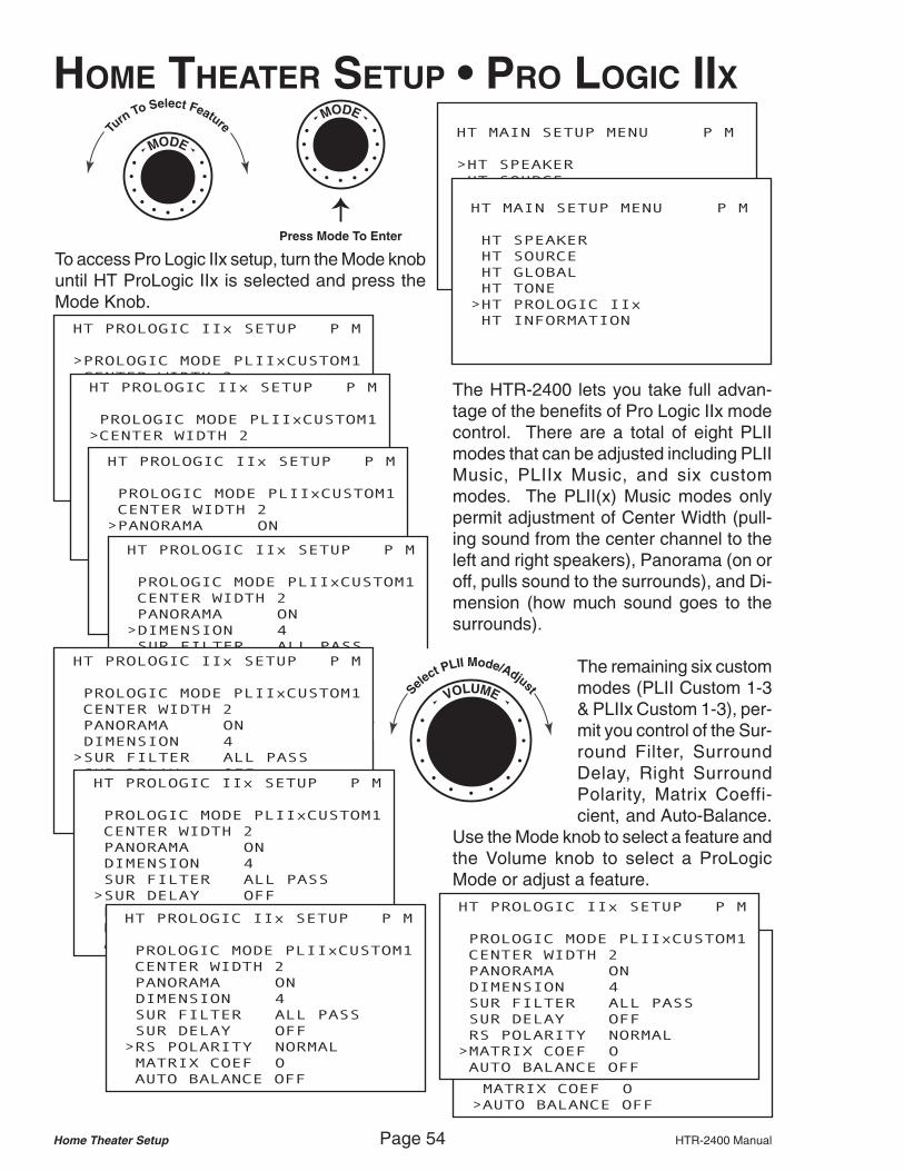
Home Theater Setup Page 54 HTR-2400 Manual
HOME THEATER SETUP • PRO LOGIC IIXTu
rnTo Select Feature
MODE
MODE
Press Mode To Enter
HT MAIN SETUP MENU P M
>HT SPEAKER
HT SOURCE
HT GLOBAL
HT TONE
HT PROLOGIC IIx
HT INFORMATION
HT MAIN SETUP MENU P M
HT SPEAKER
HT SOURCE
HT GLOBAL
HT TONE
>HT PROLOGIC IIx
HT INFORMATION HT PROLOGIC IIx SETUP P M
>PROLOGIC MODE PLIIxCUSTOM1
CENTER WIDTH 2
PANORAMA ON
DIMENSION 4
SUR FILTER ALL PASS
SUR DELAY OFF
RS POLARITY NORMAL
MATRIX COEF 0
AUTO BALANCE OFF
HT PROLOGIC IIx SETUP P M
PROLOGIC MODE PLIIxCUSTOM1
>CENTER WIDTH 2
PANORAMA ON
DIMENSION 4
SUR FILTER ALL PASS
SUR DELAY OFF
RS POLARITY NORMAL
MATRIX COEF 0
AUTO BALANCE OFF
HT PROLOGIC IIx SETUP P M
PROLOGIC MODE PLIIxCUSTOM1
CENTER WIDTH 2
>PANORAMA ON
DIMENSION 4
SUR FILTER ALL PASS
SUR DELAY OFF
RS POLARITY NORMAL
MATRIX COEF 0
AUTO BALANCE OFF
HT PROLOGIC IIx SETUP P M
PROLOGIC MODE PLIIxCUSTOM1
CENTER WIDTH 2
PANORAMA ON
>DIMENSION 4
SUR FILTER ALL PASS
SUR DELAY OFF
RS POLARITY NORMAL
MATRIX COEF 0
AUTO BALANCE OFF
HT PROLOGIC IIx SETUP P M
PROLOGIC MODE PLIIxCUSTOM1
CENTER WIDTH 2
PANORAMA ON
DIMENSION 4
SUR FILTER ALL PASS
SUR DELAY OFF
RS POLARITY NORMAL
MATRIX COEF 0
>AUTO BALANCE OFF
To access Pro Logic IIx setup, turn the Mode knobuntil HT ProLogic IIx is selected and press theMode Knob.
The HTR-2400 lets you take full advan-tage of the benefits of Pro Logic IIx modecontrol. There are a total of eight PLIImodes that can be adjusted including PLIIMusic, PLIIx Music, and six custommodes. The PLII(x) Music modes onlypermit adjustment of Center Width (pull-ing sound from the center channel to theleft and right speakers), Panorama (on oroff, pulls sound to the surrounds), and Di-mension (how much sound goes to thesurrounds).
The remaining six custommodes (PLII Custom 1-3& PLIIx Custom 1-3), per-mit you control of the Sur-round Filter, SurroundDelay, Right SurroundPolarity, Matrix Coeffi-cient, and Auto-Balance.
Use the Mode knob to select a feature andthe Volume knob to select a ProLogicMode or adjust a feature.
HT PROLOGIC IIx SETUP P M
PROLOGIC MODE PLIIxCUSTOM1
CENTER WIDTH 2
PANORAMA ON
DIMENSION 4
>SUR FILTER ALL PASS
SUR DELAY OFF
RS POLARITY NORMAL
MATRIX COEF 0
AUTO BALANCE OFF
HT PROLOGIC IIx SETUP P M
PROLOGIC MODE PLIIxCUSTOM1
CENTER WIDTH 2
PANORAMA ON
DIMENSION 4
SUR FILTER ALL PASS
>SUR DELAY OFF
RS POLARITY NORMAL
MATRIX COEF 0
AUTO BALANCE OFF
HT PROLOGIC IIx SETUP P M
PROLOGIC MODE PLIIxCUSTOM1
CENTER WIDTH 2
PANORAMA ON
DIMENSION 4
SUR FILTER ALL PASS
SUR DELAY OFF
>RS POLARITY NORMAL
MATRIX COEF 0
AUTO BALANCE OFF
HT PROLOGIC IIx SETUP P M
PROLOGIC MODE PLIIxCUSTOM1
CENTER WIDTH 2
PANORAMA ON
DIMENSION 4
SUR FILTER ALL PASS
SUR DELAY OFF
RS POLARITY NORMAL
>MATRIX COEF 0
AUTO BALANCE OFF
VOLUMESelect PLII Mode/Adjust

HTR-2400 Manual Page 55 PC Program Setup
PC PROGRAM SETUP - PC CONNECTIONS
There are several ADA PC Programs that can be used to setup the HTR-2400. These pro-grams mirror the functions available through the HTR-2400. Some features are only pro-grammable via PC, in particular adjustment of the Stereo Enhance and Mono Enhance modes.
ADA suggests using the PC programs whenever possible as they make this setup easier.Also, overall navigation is simplified in the PC program vs. the on-screen setup.
To connect to the HTR-2400, use theprovided RS-232 Mini-Jack to con-nect to thefront panel.Note, that therea r -pane lRS-232 portis off-linewhile thisconnector isinserted.
9 Pin D Connector (RS-232)To 1/8" Mini Connector (Stereo)
HomeTheater
AmplifiedAudioOutput
7.1 Channels
All Ouputs8 - 4Do Not Short
Outputs!Do Not Bridge
Outputs!FrontLeft
+ -
SurroundLeft
- +
Center
+ -
Surround BackLeft
Front Right Surround Right Subwoofer Surround Back Right
- +
+ - - + + - - +
AM/FM/WX Radio
(To Input)
AM/FMAntenna
Input
75
Audio Output
L RXM Radio®
(To Input)
XMAntenna
Input
50
Audio Output
L R
+ - - +L R
Room 1(8 - 2 )
+ - - +L R
Room 2(8 - 2 )
+ - - +L R
Room 3(8 - 2 )
+ - - +L R
Room 4(8 - 2 )
+ - - +L R
Room 5(8 - 2 )
+ - - +L R
Room 6(8 - 2 )
+ - - +L R
Room 7(8 - 2 )
+ - - +L R
Room 8(8 - 2 )
Room Keypad Control Connections • Use Any RJ-45 Port ADA Bus® Port RS-232 Port Theater Trigger
RJ-45 Ports Are Not Room Specific • Cat. 5 Wire Is Straight-Through 1 2 3 4 1( -) 2 (+ )
Gnd +VDCOut In
TX RX
Straight Through 12VDC Output
Set RS-232 SwitchSee IRL-5000
Component Video OutputY PB PR
Component Video Input 2
Component Video Input 1
Y PB PR
Component Video Input 3Y PB PRY PB PR
VideoIn
VideoOut
Source 2 Source 4 Source 6 Source 8
Source 1 Source 3 Source 5 Source 7
Room 5Room 7 Room 3 Room 1 &Theater
Room 8 Room 6 Room 4 Room 2
S-Video Out
2
1
S-Video Inputs
2
1
4
3
IR Emitter Outputs
RS-232Switch
IR Receiver (Learner)IRL-5000
IR LearnMode
(IRL-5000)
NormalMode
(PC Setup & RS-232Control)
Source 8 Source 7 Source 6 Source 5 Source 4 Source 3 Source 2 Source 1
Switched AC2.5 Amp Max
Per Outlet
AC4
AC3
AC2
AC1
CAUTIONRISK OF ELECTRIC SHOCK
DO NOT OPEN
ATTENTION!RISQUE DE CHOC ELECTRIQUE.
NE PAS OUVRIR
MADE IN U.S.A.
CAUTION:Disconnect Supply Cord Before Servicing.
ATTENTION:Debrancher Avant Le Depannage.
120VAC~60Hz
1200W
230VAC~50Hz
1200W
10ASB115V
5ASB230V
If Box Red
ADA Net ADA Bus
Vertical PositionReverse
10/100Base-T
HorizontalPositionNormal
Set Jumper Pins
ISOLATION
1 2 3 4
Isolated Ethernet to ADA Bus Convertor
ISO-E
USB
ADA Bus
(Connect Cat-Link To RJ-45 From WH-2000.Plug PC Into USB. Do Room Setup.)
4
3
2
1
ISO-USBCat-Link
ADA BusPower
USB PowerRx Tx
Vertical PositionReverse (Aquarius)
Horizontal (Norm.)
Set Jumpers Use theHTR-2400's
ADA Bus Jackto either the
ISO-E or ISO-USB
Use the HTR-2400'sRS-232 Port. When theRS-232 Mini Jack isconnected to theHTR-2400's front panelRS-232 jack, this RS-232port is rendered "off-line."When the front panel miniis removed, this jack is back "on-line."
Alternately, you can use therear-panel RS-232 port. If youprefer, you can also connect anISO-E (Ethernet) or ISO-USB(USB) to the HTR-2400’s rearpanel ADA Bus port.

PC Program Setup Page 56 HTR-2400 Manual
PC PROGRAM SETUP - MULTI-ROOMThe PC program for the setup of theHTR-2400’s Multi-Room system iscalled HTR-MR#.exe, where the #refers to the version number.
Here you select your Com port. TheLAN option is for use with the ISO-E. The HTR-2400 is typically set to19200 baud and CTS is usually setto Ignored. To verify communication,you can press the Global VersionRequest button. The Audio cardversion number will appear in thewindow. This will indicate that com-munication is established.
If you need to reset the multi-roomsystem of the HTR-2400, press theRestore To Factory Defaults but-ton. This will clear all presets andtrim levels.
By selecting the View Commandsand/or View Feedback options,separate windows open. These dis-play both Hex and ASCII codes assome ADA components operate onHex while others, like the Multi-roomsystem of the HTR-2400, operate onASCII. For those programming othersystems for control of the HTR-2400,the ASCII text from the View Com-mand window can be copied andthen pasted.
The Room Control tab accessesmost room specific features. As youchange tabs, it may be necessaryto request a Screen Update bypressing the small red square in thelower left hand corner of the screen.Room 1 is the default room selected.To setup other rooms, pull down onthe Room Selector window. Eitherfunction will cause the screen toupdate with the room’s current state.

HTR-2400 Manual Page 57 PC Program Setup
On the Room Control tab, you canselect Inputs, adjust Volume, Bass,Treble, Midrange, Balance, andMute on or off and Room Off or AllOff. You can also set the Loudnessand Limiter filters on or off. You canalso store Presets for Volume, Bal-ance and Tones (which include thefilter settings). You can also deter-mine whether the room turns on toits Last Used acoustical settings orwhether it Turns On with Recall 1(volume, balance and tone preset1s). ADA strongly recommends set-ting a great acoustical level, thenstoring volume, balance and tonepresets 1, and selecting Turn-On w/Recall 1. Finally, you can set aroom’s Maximum Volume Level aswell as have the room track one orseveral of the four Party Groups.
On the Party Testing & Input Trimtab, you can set the input trim levelsfor each of the eight sources. Thiswill permit you to maintain even au-dio levels while switching inputs. Ifyou want to see the current input trimlevels, press the small red squarein the lower right corner for a ScreenUpdate request. You can test yourParty Groups by selecting an inputfrom the pull down window and thenpressing the desired Party Groupbutton.
The Power Setup tab permits youto setup the HTR-2400’s four sourceAC outlets. Here, you assign asource (input) to the appropriate ACoutlet. If you have a single sourcethat can be switched via AC and thiscomponent has more than one au-dio output (more than one source onthe system), you can have its singleAC connection turn on with multipleinputs by checking the same ACoutlet for each input. Again, the redsquare cause the screen to update.

PC Program Setup Page 58 HTR-2400 Manual
PC PROGRAM SETUP - HOME THEATERThe PC program for the setup of theHTR-2400’s Home Theater systemis called HTR-HT#.exe, where the #refers to the version number.
Here you select your Com port. TheLAN option is for use with the ISO-E. The HTR-2400 is typically set to19200 baud and CTS is usually setto Ignored. To verify communication,you can press the either one of thered or blue squares. The blue barat the top of the screen will displayfeedback coming in.
By selecting the View Commandsand/or View Feedback options,separate windows open. These dis-play both Hex and ASCII codes assome ADA components operate onHex while other. The Home Theatersystem of the HTR-2400, operate onHEX but the ASCII Code will readthe function or feedback. For thoseprogramming other systems for con-trol of the HTR-2400, the string fromthe View Command window can becopied and then pasted.
By selecting the Theater side tab,you open on the Input/Record toptab. Here you can select inputs andalso determine the Final Inputwhich is the last input label that canbe accessed prior to returning to in-put 1. This permits you to limit thenumber of components the theatercan access to just the ones that areon the home theater system.
The bottom of the display permitsyou to recall the four Volume, Tone,and Balance Presets as well asadjust Volume Levels in either con-tinuous 1 dB Steps or one-shot .5dB Steps. You can also store thefour Volume Presets, Mute,Unmute, and turn the theater Off.

HTR-2400 Manual Page 59 PC Program Setup
The Pro Setup top tab reveals threePro Setup sub tabs, 1-Speakers, 2-Levels, and 3-Delays. In the 1-Speaker sub tab, you determine thespeaker size for your front left andright speakers, center speaker, leftand right surround speakers, and theback surround speakers. Here youcan determine if you one or two backsurrounds and if they are large orsmall. Please note, you always havesurround speakers. The back sur-round speakers are the optionalspeakers (for 6.1 & 7.1 surroundsound). This is also where you setthe subwoofer crossover frequency(80Hz is the THX standard cross-over frequency).
The 3-Delays sub tab permits youto set the delay level for eachspeaker. Here, the speaker thegreatest distance from the seatingarea is left at 0 Ft delay and will bethe reference speaker. All otherspeakers have their delays set to thedifference in distance between themand the reference speaker. Use ameasuring tape to determine eachspeaker’s distance. Take the great-est distance and subtract from iteach speakers distance. This is thatspeakers delay value in Ft (33 cm).
The 2-Levels sub tab lets you setthe speaker levels using the HTR-2400’s internal pink-noise generator.Here you can select to send Noiseto a specific channel and using anSPL meter, raise or lower thatchannel’s level so that the meter isaveraging -75 dB (C weighted, Slowsetting). You can also raise or lowerspeakers by group (front, surroundand back). Finally, this is where youcan store up to four Balance Pre-sets which contain both levels anddelays. Once one preset is storedrepeat these steps for other seatingpositions in the theater.
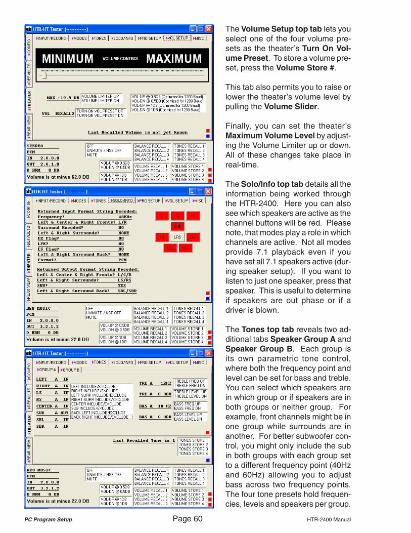
PC Program Setup Page 60 HTR-2400 Manual
The Volume Setup top tab lets youselect one of the four volume pre-sets as the theater’s Turn On Vol-ume Preset. To store a volume pre-set, press the Volume Store #.
This tab also permits you to raise orlower the theater’s volume level bypulling the Volume Slider.
Finally, you can set the theater’sMaximum Volume Level by adjust-ing the Volume Limiter up or down.All of these changes take place inreal-time.
The Solo/Info top tab details all theinformation being worked throughthe HTR-2400. Here you can alsosee which speakers are active as thechannel buttons will be red. Pleasenote, that modes play a role in whichchannels are active. Not all modesprovide 7.1 playback even if youhave set all 7.1 speakers active (dur-ing speaker setup). If you want tolisten to just one speaker, press thatspeaker. This is useful to determineif speakers are out phase or if adriver is blown.
The Tones top tab reveals two ad-ditional tabs Speaker Group A andSpeaker Group B. Each group isits own parametric tone control,where both the frequency point andlevel can be set for bass and treble.You can select which speakers arein which group or if speakers are inboth groups or neither group. Forexample, front channels might be inone group while surrounds are inanother. For better subwoofer con-trol, you might only include the subin both groups with each group setto a different frequency point (40Hzand 60Hz) allowing you to adjustbass across two frequency points.The four tone presets hold frequen-cies, levels and speakers per group.
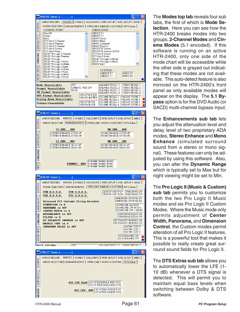
HTR-2400 Manual Page 61 PC Program Setup
The Modes top tab reveals four subtabs, the first of which is Mode Se-lection. Here you can see how theHTR-2400 breaks modes into twogroups, 2-Channel Modes and Cin-ema Modes (5.1 encoded). If thissoftware is running on an activeHTR-2400, only one side of themode chart will be accessible whilethe other side is grayed out indicat-ing that these modes are not avail-able. This auto-detect feature is alsomirrored on the HTR-2400’s frontpanel as only available modes willappear on the display. The 5.1 By-pass option is for the DVD Audio (orSACD) multi-channel bypass input.
The Enhancements sub tab letsyou adjust the attenuation level anddelay level of two proprietary ADAmodes, Stereo Enhance and MonoEnhance (simulated surroundsound from a stereo or mono sig-nal). These features can only be ad-justed by using this software. Also,you can alter the Dynamic Rangewhich is typically set to Max but fornight viewing might be set to Min.
The Pro Logic II (Music & Custom)sub tab permits you to customizeboth the two Pro Logic II Musicmodes and six Pro Logic II CustomModes. Where the Music mode onlypermits adjustment of CenterWidth, Panorama, and DimensionControl, the Custom modes permitalteration of all Pro Logic II features.This is a powerful tool that makes itpossible to really create great sur-round sound fields for Pro Logic II.
The DTS Extras sub tab allows youto automatically lower the LFE (1-10 dB) whenever a DTS signal isdetected. This will permit you tomaintain equal bass levels whenswitching between Dolby & DTSsoftware.

PC Program Setup Page 62 HTR-2400 Manual
The Defaults side tab reveals twotop tabs. Here HTR-Theater Down-load top tab permits you to selectan input number and customize it toyour specific system. If you havealready limited the number of inputsfor the theater, this is your chanceto relabel the remaining inputs, as-sign the audio and video jacks, turnon the low-voltage trigger if it is be-ing used, assign source AC triggersand setup the Double-Default ModeAuto-Detection (5.1 Cinema Mode-left, 2-Channel Mode-right).
As an example, instead of setting theFinal Input number to 11 (the num-ber of components on the system),we have set it to 12. Because theDVD Player is used for both film andmusic playback (CDs), we are go-ing to setup two inputs for the DVDPlayer, DVD FILM and DVD MUSIC.The only real differences betweenthese two input labels will be theDefault Modes.
In the screen shot to the left, you cansee that input label 2 now reads DVDMusic and is linked to the same au-dio and video jacks as input label 1,DVD Film since these two input la-bels access the same component.The only differences are the DefaultModes, where DVD Film uses filmoriented surround modes and DVDMusic uses music oriented modes.
The Factory Defaults top tab per-mits you to recall the HTR-2400’sfactory defaults which will reset theHTR-2400’s home theater section tothe original settings. Pressing Fac-tory Default Store option will load thecurrent settings as the factory de-fault. The HTR-2400 also featuresan Installer Default, which can bestored and later recalled by the enduser in the event the customer hasbadly altered the home theater.

HTR-2400 Manual Page 63 PC Program Setup
PC PROGRAM SETUP - TUNERSThe PC program for the setup of the HTR-2400’s two Tuners is called HTR-TN#.exe,where the # refers to the version number.
Here you select your Com port. The LANoption is for use with the ISO-E. The HTR-2400 is typically set to 19200 baud and CTSis usually set to Ignored. As with the Multi-Room and Home Theater PC programs, youcan select to view commands or feedback byselecting their view option box.
The Control top tab reveals the tuner con-trols and the red squares are update requests.
To control a specific tuner, select its Slot #.The other buttons on this page will now con-trol the tuner selected. If you have selectedthe XM Tuner, several of the buttons permityou to determine signal strength as well assignal diagnostics. Again, you can fully con-trol both tuners just as you would from thefront panel of the HTR-2400.
When you select a Slot # top tab, you canpull the existing tuner presets by selectingRetrieve All. Now you can select a TunerBand, select a frequency, and relabel the pre-set number (i.e. JAZZ, WABC, NEWS, etc.).You can repeat these steps for as many as30 presets per tuner module. This also per-mits you to overwrite existing presets or elimi-nate presets entirely. You can also set a sta-tion to stereo or mono (FM only) and adjustfilters. The XM tuner only permits entering ofpreset channel numbers.
You can save this tuner file or load in previ-ously saved tuner files.

PC Program Setup Page 64 HTR-2400 Manual
PC PROGRAM SETUP - IR LEARNERThe HTR-2400’s IR Learner is the IRL-5000 which is programmed via ADA’s IRL-3000 soft-ware and is somewhat different from the other ADA programs. This program is downloadedas a zipped file. The most common mistake made during installation of the software is thatthe dealer attempts to run the installer from inside the Winzip window. This will not work.Select all files in the Winzip window and choose extract, targeting your desk top. A folder willappear on your desk top. Open it and then run the installer. Once the installation is complete,you will find a new folder named ADA in your C Drive and in it is a folder called IRL-3000.
ADA strongly suggests following these steps as the IRL is not difficult to programproperly but requires you to take the time to do it correctly. Rushing through the IRLsetup will waste your time. Also, while the IRL can be loaded at the job site, it is best todo this in your shop where: lighting conditions can be controlled; your gear isn’t strewnall over the floor; and you have the time to capture, test, and load the IRL properly.Because the IRL in the HTR is the same as a stand alone IRL-5000, you can use an IRL-5000 to capture and test your commands. Later, you can take the PC to the job site andload the HTR-2400 through its front panel RS-232 port. Either way, follow these steps.
Step 1 - Folder StructureOpen the C Drive. Then open theADA folder. Then open the IRL-3000 folder. Here you will see sev-eral files including the Ir-codesfolder. In the Ir-codes folder cre-ate a new folder called Customeras well as a new folder for everymake of source gear you need tocapture code for. Then open the“manufacturer” folders and createa new folder for each model num-ber. Please note, you must keepnames to only eight charactersand avoid using spaces or / intheir name.
Source 2 Source 4 Source 6 Source 8 Room 5Room 7 Room 3 RoomThea
IR Emitter Outputs
RS-232Switch
IR Receiver (Learner)IRL-5000
IR LearnMode
(IRL-5000)
NormalMode
(PC Setup & RS-232Control)
Source 8 Source 7 Source 6 Source 5 Source 4 Source 3 Source 2 Source 1
Step 2 - Connection to PC & Opening the ProgramTurn on the HTR-2400 and connect your PC to eitherits front panel RS-232 port or the rear panel RS-232port and then flip the small red switch on the back ofthe HTR-2400 to the right (IR Learn Mode). You canalso communicate to the HTR-2400’s rear panel ADABus port via an ISO-E or ISO-USB. Here you do notneed to flip the switch to the IR Learn Mode position.
The IRL-3000 program will appear under the applica-tions window or in the IRL-3000 folder (PROGADA.exefor “Program ADA”). After you have connected the PCto the HTR, start the application. If you get an errormessage, check your RS-232 cable, the IR LearnerSwitch position and/or your Com port under Config.
IR LearnSwitch
IR TestPort 1
IR Receiver(Capture)
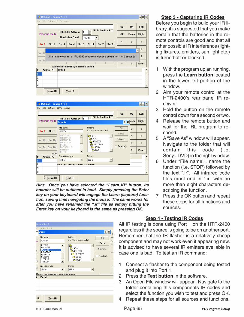
HTR-2400 Manual Page 65 PC Program Setup
Step 3 - Capturing IR CodesBefore you begin to build your IR li-brary, it is suggested that you makecertain that the batteries in the re-mote controls are good and that allother possible IR interference (light-ing fixtures, emitters, sun light etc.)is turned off or blocked.
1 With the program up an running,press the Learn button locatedin the lower left portion of thewindow.
2 Aim your remote control at theHTR-2400’s rear panel IR re-ceiver.
3 Hold the button on the remotecontrol down for a second or two.
4 Release the remote button andwait for the IRL program to re-spond.
5 A “Save As” window will appear.Navigate to the folder that willcontain this code (i.e.Sony...DVD) in the right window.
6 Under “File name:”, name thefunction (i.e. STOP) followed bythe text “.ir”. All infrared codefiles must end in “.ir” with nomore than eight characters de-scribing the function.
7 Press the OK button and repeatthese steps for all functions andsources.
Hint: Once you have selected the “Learn IR” button, itsboarder will be outlined in bold. Simply pressing the Enterkey on your keyboard will engage the Learn (capture) func-tion, saving time navigating the mouse. The same works forafter you have renamed the “.ir” file as simply hitting theEnter key on your keyboard is the same as pressing OK.
Step 4 - Testing IR CodesAll IR testing is done using Port 1 on the HTR-2400regardless if the source is going to be on another port.Remember that the IR flasher is a relatively cheapcomponent and may not work even if appearing new.It is advised to have several IR emitters available incase one is bad. To test an IR command:
1 Connect a flasher to the component being testedand plug it into Port 1.
2 Press the Test button in the software.3 An Open File window will appear. Navigate to the
folder containing this components IR codes andselect the function you wish to test and press OK.
4 Repeat these steps for all sources and functions.
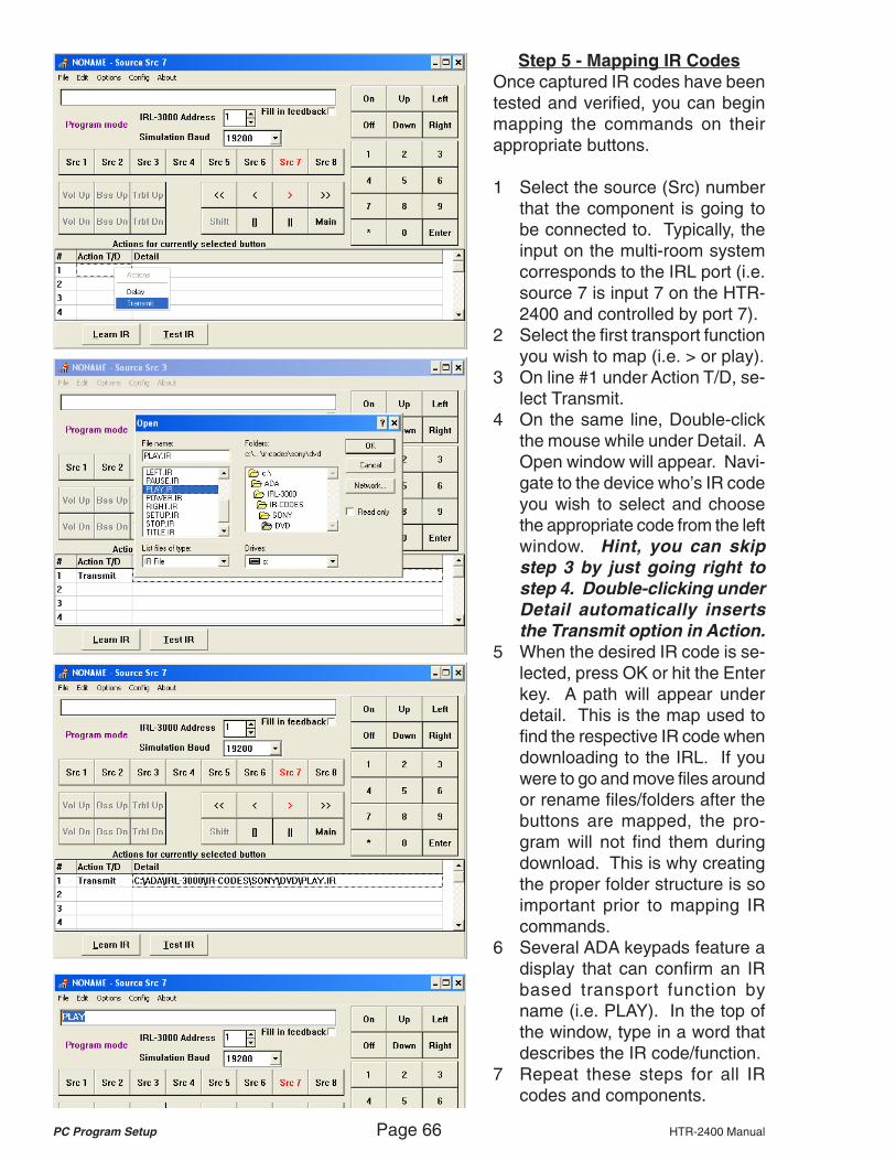
PC Program Setup Page 66 HTR-2400 Manual
Step 5 - Mapping IR CodesOnce captured IR codes have beentested and verified, you can beginmapping the commands on theirappropriate buttons.
1 Select the source (Src) numberthat the component is going tobe connected to. Typically, theinput on the multi-room systemcorresponds to the IRL port (i.e.source 7 is input 7 on the HTR-2400 and controlled by port 7).
2 Select the first transport functionyou wish to map (i.e. > or play).
3 On line #1 under Action T/D, se-lect Transmit.
4 On the same line, Double-clickthe mouse while under Detail. AOpen window will appear. Navi-gate to the device who’s IR codeyou wish to select and choosethe appropriate code from the leftwindow. Hint, you can skipstep 3 by just going right tostep 4. Double-clicking underDetail automatically insertsthe Transmit option in Action.
5 When the desired IR code is se-lected, press OK or hit the Enterkey. A path will appear underdetail. This is the map used tofind the respective IR code whendownloading to the IRL. If youwere to go and move files aroundor rename files/folders after thebuttons are mapped, the pro-gram will not find them duringdownload. This is why creatingthe proper folder structure is soimportant prior to mapping IRcommands.
6 Several ADA keypads feature adisplay that can confirm an IRbased transport function byname (i.e. PLAY). In the top ofthe window, type in a word thatdescribes the IR code/function.
7 Repeat these steps for all IRcodes and components.

HTR-2400 Manual Page 67 PC Program Setup
Step 6 - Main CommandThe HTR-2400 does not feature anautomatic On and Off function thattracks source usage. This featureis only available on the Suite 16 andSuite 8x8 systems. As such the IRLOn and Off buttons only work fromthe HTR-2400’s front panel.
The “Main” function refers to a com-mand released by repeatedly press-ing the source button on the keypadafter the source has already beenselected (on the MC-6011, this is thefunction released by pressing theSEL button). For a CD player thiscould be disc skip and for a SAT,DVD or VCR it could be power onand off.
You load the IR code for this func-tion just as you would all other com-mands as noted on the previouspage.
Step 7 - Macro CommandsThe IRL permits you to map out amacro command that could be aslong as sixteen steps. This is use-ful for SAT receivers where insteadof using the numeric pad to enter ina channel number, a single buttonpress might be used to recall a spe-cific SAT music channel. Here youcan even program in a display name(i.e. DSS JAZZ) which will appearmomentarily when say the number1 is pressed. Alternately, you canalso use the macro command to is-sue a Power On and Play sequenceas in our example. To do so:
1 After entering the line 1 com-mand as discussed, on line 2under Action T/D, select Delay.
2 Double click slowly under detailand enter your delay in ms.
3 On line 3, select the next IR com-mand as previously discussed.
4 Add a label in the top window.

PC Program Setup Page 68 HTR-2400 Manual
Step 8 - Saving IRS FilesOnce a source has been completelypopulated with IR codes and appro-priately labeled, you can save theentire source configuration as anIRS file (IR Source file). This is criti-cal in that once you have a library ofIR files complete with IRS files, youcan load an IRL in minutes. To savea source file as a reusable IRS file:
1 Place the mouse cursor over thesource (Src #) button and rightclick.
2 Select Save Source.3 A “Save As” window will appear.
Using the window on the right,navigate to the source folder forthis device. IRS files should re-side with the sources IR codes.
4 Name this file with no more thaneight characters followed by theending “.irs”. All IR source filesend in “.irs”. In this example, weare calling this file “DVD.irs”.
Step 9 - Loading IRS FilesBecause IRS files contain all buttonmaps and feedback names, they arethe ideal way to load an IRL from aproven and tested IR library. To loada source file:
1 Place the mouse cursor over thesource (Src #) button and rightclick.
2 Select Load Source.3 A “Open” window will appear. Us-
ing the window on the right, navi-gate to the source folder for thisdevice and then select the IRSfile.
The entire source file will now loadonto this IRL port. If you alreadyhave developed an IRL library, youcan repeat these steps for othersources on your IRL.

HTR-2400 Manual Page 69 PC Program Setup
Step 10 - Saving ADA FilesOnce you have built an entire IRLfor a customer, you can save thelayout as an ADA customer file. AllADA customer files can be no morethan eight characters in length andmust end in “.ada”. To save a file:
1 From the File pull down windowselect “Save As.”
2 A Save As window will open.Navigate to the Customer folderin the right window and then typein a project name under Filename. The project name couldbe the customer’s name followedby the “.ada” ending.
3 Then press OK.
Step 11 - Loading ADA FilesTo load an ADA file, select Openfrom the pull down menu under File.An Open window will appear. Navi-gate to the Customer folder in theright window and then select theproject you wish to open.
Step 12 - Downloading to IRLOnce you have built an entire IRLfor a customer you are ready to load(download) to the IRL. Please note,that if the IRL has already beenpreviously loaded, this step willerase all codes currently in theIRL. As such, if you are adding acomponent, you will need todownload all source files and notjust the new components.
1 Check the “Fill in feedback” box.2 From the Options pull down win-
dow select “Download.”
The IRL will automatically begin theprocess of downloading to the IRL.The screen will flash buttons as theyare being loaded. When the flash-ing ends, the IRL is loaded.

PC Program Setup Page 70 HTR-2400 Manual
Step 13 - Simulation ModeOnce the IRL has been loaded, youcan now test the individual IR portsby using your PC as a keypad.
1 Connect the sources’ IR flashersto their permanent IR ports onthe back of the HTR-2400.
2 Under the “Options” pull downwindow, select “SimulationMode.”
3 Select source number (Src #)and then various functions.Verify that the command func-tions are working.
4 Verify that the feedback is dis-playing at the top of the screen.Please note, that the additionalnumbers in the brackets will notappear on the keypad’s display.
Source 2 Source 4 Source 6 Source
IR Emit
RS-232Switch
IR ReceiIR LearnMode
(IRL-5000)
NormalMode
(PC Setup & RS-232Control)
Source 8 Source 7 Source 6 Source
IR LearnSwitch
Step 14 - DisconnectionOnce all sources are functioning, you can close the application. If youare connected to either the HTR-2400’s front or rear panel RS-232 ports,remember to flip the red IRL Learn Switch on the back of the HTR-2400back to “Normal Mode.” At this time, ADA recommends powering downthe HTR-2400 for a few moments and then powering it back up again.Assuming that you have already programmed the HTR-2400 source con-figuration (multi-room and home theater setup), you are ready to test theHTR-2400 front panel transport buttons.
Trouble-Shooting IR CodesADA provides an IR Test program(IRTest) on its web site that permitsyou to analyze an IR file that maynot be working. Often this requiresjust a slight change to the IR codesfrequency. The IR Test program canmodify captured “.ir” files or can work
with the IRL to capture andtest new IR files. Here youcan open a “.ir” file underFile/Load. The file will ap-pear in wave form and thecarrier will display. UnderOptions you elect tochange the carrier.

HTR-2400 Manual Page 71 RS-232 Codes
RS-232 CODES - MULTI-ROOMHTR 2400 MULTIROOM AUDIO SERIAL PROTOCOL V3.1
STRING START ACTION PREFIX PART 2 GLOBAL PART 3
FUNCTION CHARACTER DO (SET) GET FUNCTION R01 TO R08
INPUT UP ` S G INUP R01
INPUT DOWN ` S G INDN R01
INPUT 1 ` S G AD01 R01
INPUT 2 ` S G AD02 R01
INPUT 3 ` S G AD03 R01
INPUT 4 ` S G AD04 R01
INPUT 5 ` S G AD05 R01
INPUT 6 ` S G AD06 R01
INPUT 7 ` S G AD07 R01
INPUT 8 ` S G AD08 R01
MUTE TOGGLE ` S G MTOG R01
MUTE ON ` S G MTON R01
MUTE OFF ` S G MTOF R01
ROOM OFF ` S G RMOF R01
VOLUME UP ` S G VLUP R01
VOLUME DN ` S G VLDN R01
BASS UP ` S G BSUP R01
BASS DN ` S G BSDN R01
MIDRANGE UP ` S G MDUP R01
MIDRANGE DN ` S G MDDN R01
TREBLE UP ` S G TRUP R01
TREBLE DN ` S G TRDN R01
ALL TONES FLAT ` S G FLAT R01
TONE RECALL UP + FLAT ` S G TNUP R01
TONE RECALL 1 ` S G TNR1 R01
TONE RECALL 2 ` S G TNR2 R01
TONE RECALL 3 ` S G TNR3 R01
TONE RECALL 4 ` S G TNR4 R01
TONE STORE 1 ` S G TNS1 R01
TONE STORE 2 ` S G TNS2 R01
TONE STORE 3 ` S G TNS3 R01
TONE STORE 4 ` S G TNS4 R01
VOLUME RECALL 1 ` S G VLR1 R01
VOLUME RECALL 2 ` S G VLR2 R01
VOLUME RECALL 3 ` S G VLR3 R01
VOLUME RECALL 4 ` S G VLR4 R01
VOLUME STORE 1 ` S G VLS1 R01
VOLUME STORE 2 ` S G VLS2 R01
VOLUME STORE 3 ` S G VLS3 R01
VOLUME STORE 4 ` S G VLS4 R01
LOUDNESS ON ` S G LDON R01
LOUDNESS OFF ` S G LDOF R01
LIMITER ON ` S G LMON R01
LIMITER OFF ` S G LMOF R01
VOLUME DIRECT ` S G V0## R01
BASS DIRECT ` S G B### R01
MIDRANGE DIRECT ` S G M### R01
TREBLE DIRECT ` S G T### R01
BALANCE LEFT ` S G BALL R01
BALANCE RIGHT ` S G BALR R01
BALANCE EQUAL ` S G BLEQ R01
BALANCE RECALL 1 ` S G BLR1 R01
BALANCE RECALL 2 ` S G BLR2 R01
BALANCE STORE 1 ` S G BLS1 R01
BALANCE STORE 2 ` S G BLS2 R01
INPUT LEVEL TRIM 1 ` S G IT01 G##
INPUT LEVEL TRIM 2 ` S G IT02 G##
INPUT LEVEL TRIM 3 ` S G IT03 G##
INPUT LEVEL TRIM 4 ` S G IT04 G##
INPUT LEVEL TRIM 5 ` S G IT05 G##
INPUT LEVEL TRIM 6 ` S G IT06 G##
INPUT LEVEL TRIM 7 ` S G IT07 G##
INPUT LEVEL TRIM 8 ` S G IT08 G##
ALL OFF ` S G ALOF G00
PARTY SET 1 ` S G PTS1 R01
PARTY SET 2 ` S G PTS2 R01
PARTY SET 3 ` S G PTS3 R01
PARTY SET 4 ` S G PTS4 R01
PARTY CLEAR 1 ` S G PTC1 R01
PARTY CLEAR 2 ` S G PTC2 R01
PARTY CLEAR 3 ` S G PTC3 R01
PARTY CLEAR 4 ` S G PTC4 R01
PARTY 1 ` S PTY1 G##
PARTY 2 ` S PTY2 G##
PARTY 3 ` S PTY3 G##
PARTY 4 ` S PTY4 G##
` S G PS## G##
S G PC## G##
MAXIMUM VOLUME LEVEL ` S G MV## R01
RESTORE FACTORY DEFAULTS ` S FDEF G00
ALL UPDATE ` G ALRM G00
ROOM UPDATE ` G ROOM R01
ALL ROOM CONTROL UPDATE ` G ALRC G00
ROOM CONTROL UPDATE ` G RCON R01
VERSION REQUEST ` G VERS G00
ECHO ` E # of bytes to follow 1-255 bytes to be sent

RS-232 Codes Page 72 HTR-2400 Manual
RS-232 CODES - HOME THEATERCOMMAND STRING BREAKDOWNCMDA010B0MSCINP1<cr>
Where:
CMD <- preamble NOTE: IT IS POSSIBLE TO HAVE LENGTH AS A CONSTANT,
A <-data type BY USING A PLACEHOLDER SUCH AS A SPACE OR
010 <- length till <cr> (in decimal) EXCLAMATION POINT IN THE COMMAND STRING.
B <- system type FOR EXAMPLE: CMDA015B0MSCINP1!!!!!<cr>
0 <- system address
MSCINP1 <- string LONGEST LENGTH CAN ONLY BE UP TO 015.
<cr> <- carriage return (0x0D)
FEEDBACK STRING BREAKDOWNFBKC018B0VOL -40.5 DB023<cr>
Where:
FBK <- preamble
C <-data type
018 <- length till <cr> (in decimal) NOTE: LENGTH WILL ALWAYS BE 018 FOR ALL ASCII
B <- system type FEEDBACK STRINGS.
0 <- system address
VOL -40.5 DB <- 12 character string
023 <- index from string
<cr> <- carriage return (0x0D)
ASCII COMMANDSMISC, UPDATE REQUEST MSC UPD ALL UPDATE - SEND ALL POSSIBLE INFORMAT
MISC, UPDATE REQUEST MSC UPD VER1 UPDATE - MICRO VERSION
MISC, UPDATE REQUEST MSC UPD VER2 UPDATE - PROM VERSION
MISC, UPDATE REQUEST MSC UPD VER3 UPDATE - DSP VERSION
MISC, UPDATE REQUEST (APPLICABLE IN THX HW) MSC UPD ASA UPDATE - THX'S ASA
MISC, UPDATE REQUEST (APPLICABLE IN THX HW) MSC UPD FLT UPDATE - THX'S RE-EQ - TIMBRE - DEC
MISC, UPDATE REQUEST MSC UPD MST UPDATE - MASTER VOLUME
MISC, UPDATE REQUEST MSC UPD VAR1 UPDATE - INPUT - MASTER VOLUME - FO
MISC, UPDATE REQUEST MSC UPD VAR2 UPDATE - MASTER VOLUME - FORMAT - M
MISC, UPDATE REQUEST MSC UPD VAR3 UPDATE - MASTER VOLUME - MAXIMUM VO
MISC, UPDATE REQUEST MSC UPD VAR4 UPDATE - INPUT - MASTER VOLUME - FO
MISC, UPDATE REQUEST MSC UPD VOL UPDATE - (BALANCE) C - SUB - L - R
MISC, UPDATE REQUEST MSC UPD DLY UPDATE - (DELAY) C - SUB - L - R -
MISC, UPDATE REQUEST MSC UPD SPK UPDATE - (SPEAKER SETUP) LR - C - S
MISC, UPDATE REQUEST MSC UPD SOL UPDATE - SOLO TEST
MISC, UPDATE REQUEST MSC UPD TNA UPDATE - INCLUDE/EXCLUDE & FREQS &
MISC, UPDATE REQUEST MSC UPD TNB UPDATE - INCLUDE/EXCLUDE & FREQS &
MISC, UPDATE REQUEST MSC UPD FNL UPDATE - FINAL INPUT
MISC, UPDATE REQUEST MSC UPD PL2 UPDATE - PLII/PLIIx MUSIC AND CUSTO
MISC, UPDATE REQUEST MSC UPD INP UPDATE - INPUT SELECTED
MISC, UPDATE REQUEST MSC UPD TRN UPDATE - TURN-ON INPUT
MISC, UPDATE REQUEST MSC UPD XVR UPDATE - CROSSOVER
MODE, UP/DN FOR ANY INPUT FORMAT MDE MSC UP DN
MODE, MULTI-PIN INPUT MDE MIN DIR51 MODE - DISCRETE + DIRECT 5.1
MODE, MULTI-PIN INPUT MDE MIN DIR71 MODE - DISCRETE + DIRECT 7.1
MODE, MULTI-CHANNEL INPUT MDE 5.1 DIR51 MODE - DISCRETE + DIRECT 5.1
MODE, MULTI-CHANNEL INPUT MDE 5.1 DIR71 MODE - DISCRETE + DIRECT 7.1 + ES/E
MODE, MULTI-CHANNEL INPUT MDE 5.1 ST MODE - STEREO DOWNMIX
MODE, MULTI-CHANNEL INPUT MDE 5.1 MN MODE - MONO DOWNMIX
MODE, MULTI-CHANNEL INPUT MDE 5.1 3CH MODE - 3 CHANNEL DOWNMIX
MODE, MULTI-CHANNEL INPUT MDE 5.1 PHAN MODE - PHANTOM DOWNMIX
MODE, MULTI-CHANNEL INPUT MDE 5.1 CIN MODE - DISCRETE
MODE, MULTI-CHANNEL INPUT (APPLICABLE IN THX HW) MDE 5.1 CIN+ MODE - DISCRETE + THX
MODE, MULTI-CHANNEL INPUT MDE 5.1 EXES MODE - DISCRETE + EX/ES
MODE, MULTI-CHANNEL INPUT (APPLICABLE IN THX HW) MDE 5.1 EXES+ MODE - THX + EX/ES
MODE, MULTI-CHANNEL INPUT MDE 5.1 NEO MODE - DISCRETE + NEO:6 CINEMA
MODE, MULTI-CHANNEL INPUT (APPLICABLE IN THX HW) MDE 5.1 NEO+ MODE - THX + NEO:6 CINEMA
MODE, MULTI-CHANNEL INPUT MDE 5.1 NEOMSC MODE - DISCRETE + NEO:6 MUSIC
MODE, MULTI-CHANNEL INPUT MDE 5.1 MVEEX MODE - DISCRETE + PLIIx MOVIE
MODE, MULTI-CHANNEL INPUT (APPLICABLE IN THX HW) MDE 5.1 MVEEX+ MODE - THX + PLIIx MOVIE
MODE, MULTI-CHANNEL INPUT MDE 5.1 MSCEX MODE - DISCRETE + PLIIx MUSIC
MODE, MULTI-CHANNEL INPUT (APPLICABLE IN THX HW) MDE 5.1 THX2 MODE - THX ULTRA2 CINEMA
MODE, MULTI-CHANNEL INPUT (APPLICABLE IN THX HW) MDE 5.1 THX2G MODE - THX ULTRA2 GAME
MODE, MULTI-CHANNEL INPUT (APPLICABLE IN THX HW) MDE 5.1 THX2A MODE - THX ULTRA2 ADVANCED
MODE, MULTI-CHANNEL INPUT (APPLICABLE IN THX HW) MDE 5.1 THX2M MODE - THX ULTRA2 MUSICMODE
MODE, MULTI-CHANNEL INPUT MDE 5.1 HALL1 MODE - HALL1 DOWNMIX
MODE, MULTI-CHANNEL INPUT MDE 5.1 HALL2 MODE - HALL2 DOWNMIX
MODE, MULTI-CHANNEL INPUT MDE 5.1 HALL3 MODE - HALL3 DOWNMIX
MODE, MULTI-CHANNEL INPUT MDE 5.1 CRCH1 MODE - CHURCH1 DOWNMIX
MODE, MULTI-CHANNEL INPUT MDE 5.1 CRCH2 MODE - CHURCH2 DOWNMIX
MODE, MULTI-CHANNEL INPUT MDE 5.1 CLUB1 MODE - CLUB1 DOWNMIX
MODE, MULTI-CHANNEL INPUT MDE 5.1 CLUB2 MODE - CLUB2 DOWNMIX
MODE, MULTI-CHANNEL INPUT MDE 5.1 CLUB3 MODE - CLUB3 DOWNMIX
MODE, MULTI-CHANNEL INPUT MDE 5.1 STDM1 MODE - STADIUM1 DOWNMIX
MODE, MULTI-CHANNEL INPUT MDE 5.1 STDM2 MODE - STADIUM2 DOWNMIX
MODE, MULTI-CHANNEL INPUT MDE 5.1 THETR1 MODE - THEATER1 DOWNMIX
MODE, MULTI-CHANNEL INPUT MDE 5.1 THETR2 MODE - THEATER2 DOWNMIX
MODE, TWO-CHANNEL INPUT MDE 2.0 DIR20 MODE - DIRECT 2.0
MODE, TWO-CHANNEL INPUT MDE 2.0 ST MODE - STEREO
MODE, TWO-CHANNEL INPUT MDE 2.0 MN MODE - MONO
MODE, TWO-CHANNEL INPUT MDE 2.0 VTL MODE - ADA VIRTUAL (aka AGL Enhance
MODE, TWO-CHANNEL INPUT MDE 2.0 QUAD MODE - ADA QUADBYPASS
MODE, TWO-CHANNEL INPUT MDE 2.0 STE MODE - ADA STEREO ENHANCE
MODE, TWO-CHANNEL INPUT MDE 2.0 MNE MODE - ADA MONO ENHANCE
MODE, TWO-CHANNEL INPUT MDE 2.0 ST5 MODE - ADA STEREO 5
MODE, TWO-CHANNEL INPUT MDE 2.0 MN5 MODE - ADA MONO 5

HTR-2400 Manual Page 73 RS-232 Codes
MODE, TWO-CHANNEL INPUT MDE 2.0 NEO3CH MODE - DTS NEO 3CH
MODE, TWO-CHANNEL INPUT MDE 2.0 NEOPHA MODE - DTS NEO PHANTOM
MODE, TWO-CHANNEL INPUT MDE 2.0 NEO5 MODE - DTS NEO 5CH
MODE, TWO-CHANNEL INPUT MDE 2.0 NEO MODE - DTS NEO:6 CINEMA
MODE, TWO-CHANNEL INPUT (APPLICABLE IN THX HW) MDE 2.0 NEO+ MODE - DTS NEO:6 CINEMA + THX
MODE, TWO-CHANNEL INPUT MDE 2.0 NEOMSC MODE - DTS NEO:6 MUSIC
MODE, TWO-CHANNEL INPUT MDE 2.0 3CH MODE - DOLBY 3 CHANNEL
MODE, TWO-CHANNEL INPUT MDE 2.0 PHAN MODE - DOLBY PHANTOM
MODE, TWO-CHANNEL INPUT MDE 2.0 PL MODE - DOLBY PLII PROLOGIC
MODE, TWO-CHANNEL INPUT (APPLICABLE IN THX HW) MDE 2.0 PL+ MODE - DOLBY PLII PROLOGIC + THX
MODE, TWO-CHANNEL INPUT MDE 2.0 MTX MODE - DOLBY PLII MATRIX
MODE, TWO-CHANNEL INPUT MDE 2.0 MTXEX MODE - DOLBY PLIIx MATRIX
MODE, TWO-CHANNEL INPUT MDE 2.0 GME MODE - DOLBY PLII GAME
MODE, TWO-CHANNEL INPUT MDE 2.0 GMEEX MODE - DOLBY PLIIx GAME
MODE, TWO-CHANNEL INPUT MDE 2.0 MSC MODE - DOLBY PLII MUSIC
MODE, TWO-CHANNEL INPUT MDE 2.0 MSCEX MODE - DOLBY PLIIx MUSIC
MODE, TWO-CHANNEL INPUT MDE 2.0 MVE MODE - DOLBY PLII MOVIE
MODE, TWO-CHANNEL INPUT (APPLICABLE IN THX HW) MDE 2.0 MVE+ MODE - DOLBY PLII MOVIE + THX
MODE, TWO-CHANNEL INPUT MDE 2.0 MVEEX MODE - DOLBY PLIIx MOVIE
MODE, TWO-CHANNEL INPUT (APPLICABLE IN THX HW) MDE 2.0 MVEEX+ MODE - DOLBY PLIIx MOVIE + THX
MODE, TWO-CHANNEL INPUT MDE 2.0 CS1 MODE - DOLBY PLII CUSTOM1
MODE, TWO-CHANNEL INPUT (APPLICABLE IN THX HW) MDE 2.0 CS1+ MODE - DOLBY PLII CUSTOM1 + THX
MODE, TWO-CHANNEL INPUT MDE 2.0 CS1EX MODE - DOLBY PLIIx CUSTOM1
MODE, TWO-CHANNEL INPUT (APPLICABLE IN THX HW) MDE 2.0 CS1EX+ MODE - DOLBY PLIIx CUSTOM1 + THX
MODE, TWO-CHANNEL INPUT MDE 2.0 CS2 MODE - DOLBY PLII CUSTOM2
MODE, TWO-CHANNEL INPUT (APPLICABLE IN THX HW) MDE 2.0 CS2+ MODE - DOLBY PLII CUSTOM2 + THX
MODE, TWO-CHANNEL INPUT MDE 2.0 CS2EX MODE - DOLBY PLIIx CUSTOM2
MODE, TWO-CHANNEL INPUT (APPLICABLE IN THX HW) MDE 2.0 CS2EX+ MODE - DOLBY PLIIx CUSTOM2 + THX
MODE, TWO-CHANNEL INPUT MDE 2.0 CS3 MODE - DOLBY PLII CUSTOM3
MODE, TWO-CHANNEL INPUT (APPLICABLE IN THX HW) MDE 2.0 CS3+ MODE - DOLBY PLII CUSTOM3 + THX
MODE, TWO-CHANNEL INPUT MDE 2.0 CS3EX MODE - DOLBY PLIIx CUSTOM3
MODE, TWO-CHANNEL INPUT (APPLICABLE IN THX HW) MDE 2.0 CS3EX+ MODE - DOLBY PLIIx CUSTOM3 + THX
MODE, TWO-CHANNEL INPUT MDE 2.0 HALL1 MODE - HALL1
MODE, TWO-CHANNEL INPUT MDE 2.0 HALL2 MODE - HALL2
MODE, TWO-CHANNEL INPUT MDE 2.0 HALL3 MODE - HALL3
MODE, TWO-CHANNEL INPUT MDE 2.0 CRCH1 MODE - CHURCH1
MODE, TWO-CHANNEL INPUT MDE 2.0 CRCH2 MODE - CHURCH2
MODE, TWO-CHANNEL INPUT MDE 2.0 CLUB1 MODE - CLUB1
MODE, TWO-CHANNEL INPUT MDE 2.0 CLUB2 MODE - CLUB2
MODE, TWO-CHANNEL INPUT MDE 2.0 CLUB3 MODE - CLUB3
MODE, TWO-CHANNEL INPUT MDE 2.0 STDM1 MODE - STADIUM1
MODE, TWO-CHANNEL INPUT MDE 2.0 STDM2 MODE - STADIUM2
MODE, TWO-CHANNEL INPUT MDE 2.0 THETR1 MODE - THEATER1
MODE, TWO-CHANNEL INPUT MDE 2.0 THETR2 MODE - THEATER2
VOLUME, MASTER VOL MST UP DN MUTE UNMUTE NSEOFF SOLOFF LMROFF
VOLUME, MASTER W/MULTI INC/DEC VOL MST 2UP 2DN 3UP 3DN 4UP 4DN 5UP 5DN
VOLUME, MASTER RECALL/STORE VOL MST 1STR 1RCL 2STR 2RCL 3STR 3RCL 4STR 4RCL
VOLUME, CENTER VOL CEN UP DN
VOLUME, SUBWOOFER VOL SUB UP DN
VOLUME, LEFT VOL LFT UP DN
VOLUME, RIGHT VOL RGT UP DN
VOLUME, LEFT SURROUND VOL LSR UP DN
VOLUME, RIGHT SURROUND VOL RSR UP DN
VOLUME, SURROUND BACK LEFT VOL SBL UP DN
VOLUME, SURROUND BACK RIGHT VOL SBR UP DN
VOLUME, FRONTS VOL FRT UP DN
VOLUME, SURROUNDS VOL SUR UP DN
VOLUME, BACKS VOL BCK UP DN
NOISE, TEST VOL NSE CEN SUB LFT RGT LSR RSR SBL SBR SEQ
SOLO, TEST VOL SOL CEN SUB LFT RGT LSR RSR SBL SBR
TURN-ON, VOLUME PRESET or LAST USED VOL TUR UP DN
VOLUME, MAX LIMITER VOL MAX UP DN
TONE, PRESET RECALL/STORE VOL TNE 1STR 1RCL 2STR 2RCL 3STR 3RCL 4STR 4RCL
BALANCE+DELAY, RECALL/STORE VOL BAL 1STR 1RCL 2STR 2RCL 3STR 3RCL 4STR 4RCL
MISC, INPUT SELECTOR AND POWER TURN-ON MSC INP 1..20 01..20
MISC, FINAL INPUT MSC FNL UP DN
MISC, POWER MSC PWR OFF UNMUTE NSEOFF SOLOFF LMROFF
MISC, COPY OF INSTALLERS SETTINGS MSC FCT 1STR 1RCL
SPEAKER, FRONTS SIZE SPK FRT SML LRG
SPEAKER, SURROUNDS SIZE SPK SUR OFF SML LRG
SPEAKER, CENTER SIZE SPK CEN OFF SML LRG
SPEAKER, BACKS SIZE SPK BCK OFF SML LRG 2SML 2LRG
SPEAKER, SUBWOOFER SIZE SPK SUB NO YES
SPEAKER, SUB CROSSOVER FILTER SPK XVR UP DN
THX, SUBWOOFER LIMITER (APPLICABLE IN THX HW) SPK LMR ON UP DN
THX, ADVANCED SPEAKER ARRAY (APPLICABLE IN THX HW) SPK ASA ON OFF 12IN 12-48 48IN
SPEAKER, DELAY CENTER DLY CEN UP DN
SPEAKER, DELAY SUB DLY SUB UP DN
SPEAKER, DELAY LEFT DLY LFT UP DN
SPEAKER, DELAY RIGHT DLY RGT UP DN
SPEAKER, DELAY LS DLY LSR UP DN
SPEAKER, DELAY RS DLY RSR UP DN
SPEAKER, DELAY SBL DLY SBL UP DN
SPEAKER, DELAY SBR DLY SBR UP DN
PL2/PL2x, DIMENSION (MODE DEPENDENT) PL2 DIM UP DN
PL2/PL2x, PANARAMA (MODE DEPENDENT) PL2 PAN ON OFF
PL2/PL2x, CENTER WIDTH (MODE DEPENDENT) PL2 CEN UP DN

RS-232 Codes Page 74 HTR-2400 Manual
PL2/PL2x, AUTO BALANCE (MODE DEPENDENT) (NOT FOR MUSIC) PL2 BAL ON OFF
PL2/PL2x, SURROUND FILTER (MODE DEPENDENT) (NOT FOR MUSIC) PL2 FTR FULL LPF SHELF
PL2/PL2x, RS INVERT (MODE DEPENDENT) (NOT FOR MUSIC) PL2 INV ON OFF
PL2/PL2x, MATRIX COEF (MODE DEPENDENT) (NOT FOR MUSIC) PL2 MTX 0COEF 1COEF 2COEF
PL2/PL2x, SURR DELAY (MODE DEPENDENT) (NOT FOR MUSIC) PL2 DLY ON OFF
PL2/PL2x, MUSIC DIMENSION CSM DIM UP DN
PL2/PL2x, MUSIC PANARAMA CSM PAN ON OFF
PL2/PL2x, MUSIC CENTER WIDTH CSM CEN UP DN
PL2/PL2x, CUSTOM1 DIMENSION CS1 DIM UP DN
PL2/PL2x, CUSTOM1 PANARAMA CS1 PAN ON OFF
PL2/PL2x, CUSTOM1 CENTER WIDTH CS1 CEN UP DN
PL2/PL2x, CUSTOM1 AUTO BALANCE CS1 BAL ON OFF
PL2/PL2x, CUSTOM1 SURROUND FILTER CS1 FTR FULL LPF SHELF
PL2/PL2x, CUSTOM1 RS INVERT CS1 INV ON OFF
PL2/PL2x, CUSTOM1 MATRIX COEF CS1 MTX 0COEF 1COEF 2COEF
PL2/PL2x, CUSTOM1 SURR DELAY CS1 DLY ON OFF
PL2/PL2x, CUSTOM2 DIMENSION CS2 DIM UP DN
PL2/PL2x, CUSTOM2 PANARAMA CS2 PAN ON OFF
PL2/PL2x, CUSTOM2 CENTER WIDTH CS2 CEN UP DN
PL2/PL2x, CUSTOM2 AUTO BALANCE CS2 BAL ON OFF
PL2/PL2x, CUSTOM2 SURROUND FILTER CS2 FTR FULL LPF SHELF
PL2/PL2x, CUSTOM2 RS INVERT CS2 INV ON OFF
PL2/PL2x, CUSTOM2 MATRIX COEF CS2 MTX 0COEF 1COEF 2COEF
PL2/PL2x, CUSTOM2 SURR DELAY CS2 DLY ON OFF
PL2/PL2x, CUSTOM3 DIMENSION CS3 DIM UP DN
PL2/PL2x, CUSTOM3 PANARAMA CS3 PAN ON OFF
PL2/PL2x, CUSTOM3 CENTER WIDTH CS3 CEN UP DN
PL2/PL2x, CUSTOM3 AUTO BALANCE CS3 BAL ON OFF
PL2/PL2x, CUSTOM3 SURROUND FILTER CS3 FTR FULL LPF SHELF
PL2/PL2x, CUSTOM3 RS INVERT CS3 INV ON OFF
PL2/PL2x, CUSTOM3 MATRIX COEF CS3 MTX 0COEF 1COEF 2COEF
PL2/PL2x, CUSTOM3 SURR DELAY CS3 DLY ON OFF
MODE, STEREO ENHANCED LEVEL MDE STA UP DN
MODE, STEREO ENHANCED DELAY MDE STD UP DN
MODE, MONO ENHANCED LEVEL MDE MNA UP DN
MODE, MONO ENHANCED DELAY MDE MND UP DN
DOLBY DIGITAL, DYNAMIC RANGE MDE DYN MIN MID MAX
THX, RE-EQ (EFFECTIVE IN NON-THX MODE) (FOR THX HW) MDE REQ ON OFF
THX, DECORROLATION (EFFECTIVE IN NON-THX MODE) (FOR THX HW) MDE DCR ON OFF
THX, TIMBER MATCH (EFFECTIVE IN NON-THX MODE) (FOR THX HW) MDE TIM ON OFF
DTS, ATTENUATE LFE DTS LFE UP DN ATTN FLAT
TONE, GROUP A CENTER INC/EXC TNA CEN INV
TONE, GROUP A SUB INC/EXC TNA SUB INV
TONE, GROUP A LEFT INC/EXC TNA LFT INV
TONE, GROUP A RIGHT INC/EXC TNA RGT INV
TONE, GROUP A LS INC/EXC TNA LSR INV
TONE, GROUP A RS INC/EXC TNA RSR INV
TONE, GROUP A SBL INC/EXC TNA SBL INV
TONE, GROUP A SBR INC/EXC TNA SBR INV
TONE, GROUP A TREBLE FREQ TNA TRF UP DN
TONE, GROUP A TREBLE LEVEL TNA TRL UP DN
TONE, GROUP A BASS FREQ TNA BSF UP DN
TONE, GROUP A BASS LEVEL TNA BSL UP DN
TONE, GROUP B CENTER INC/EXC TNB CEN INV
TONE, GROUP B SUB INC/EXC TNB SUB INV
TONE, GROUP B LEFT INC/EXC TNB LFT INV
TONE, GROUP B RIGHT INC/EXC TNB RGT INV
TONE, GROUP B LS INC/EXC TNB LSR INV
TONE, GROUP B RS INC/EXC TNB RSR INV
TONE, GROUP B SBL INC/EXC TNB SBL INV
TONE, GROUP B SBR INC/EXC TNB SBR INV
TONE, GROUP B TREBLE FREQ TNB TRF UP DN
TONE, GROUP B TREBLE LEVEL TNB TRL UP DN
TONE, GROUP B BASS FREQ TNB BSF UP DN
TONE, GROUP B BASS LEVEL TNB BSL UP DN
OTHER COMMANDSThis command will directly program the volume level in decimal (range is 000-255):
CMDL007B0D128<cr>
Feedback will resemble:
FBKC018B0VOL 0.0 DB023<cr>
This command will directly program the volume level in ASCII (range is –60.0 to max volume):
CMDL009B0V-30.0<cr>
Feedback will resemble:
FBKC018B0VOL -30.0 DB023<cr>
This command will directly program the volume level in ASCII (range is –60.0 to max volume):
CMDL011B0V-30.0DB<cr>
Feedback will resemble:
FBKC018B0VOL -30.0 DB023<cr>
RS-232 CODES - HOME THEATER (CONT.)

HTR-2400 Manual Page 75 RS-232 Codes
XM SATELLITE RADIO Hex Commands
Format of Command String Start Constant Command Bus Module End
6 Characters total B8h 4Dh command bus module B8h
Bus Address 0 = 30h 0 = 30h 1 = 20h
Bus Address 1 = 31h 1 = 31h 2 = 21h
Bus Address 2 = 32h 2 = 32h 3 = 22h
Bus Address 3 = 33h 3 = 33h
Bus Address 4 = 34h 4 = 34h
Bus Address 5 = 35h 5 = 35h
Bus Address 6 = 36h 6 = 36h
Bus Address 7 = 37h 7 = 37h
Bus Address 8 = 38h 8 = 38h
Bus Address 9 = 39h 9 = 39h
Command For Module 1 Module 2 Module 3
Normal Operation
Update Station/Song 11h 12h 13h
Channel Up 63h 73h 83h
Channel Down 64h 74h 84h
Genre Up 65h 75h 85h
Genre Down 66h 76h 86h
Station down 1Eh 1Eh 1Eh
Station up 4Dh 4Dh 4Dh
Preset Up 17h 1Dh 4Eh
Preset Down 18h 18h 18h
Get XM serial number * A0h A0h A0h
*or send 0,enter from keypad
Turn on Signal Display * B0h B0h B0h
*or send 0,0,0,enter from keypad
Get Software Version C0h C0h C0h
Preset Mode * D0h D0h D0h
*or send 0,0,enter from keypad
In Preset Mode
Select Preset Up 65h 75h 85h
Select Preset Down 66h 76h 86h
Delete Preset 1Eh 1Eh 1Eh
Escape From Preset Mode 4Dh 4Dh 4Dh
Numeric Command Format Start Constant Constant Numeric IDcode End
6 characters total Command
B8h 4Dh 97h Bus + Mod# B8h
0=00h 1=03h
1=10h 2=04h
2=20h 3=05h
3=30h
4=40h
5=50h
6=60h
7=70h
8=80h
9=90h
Number 0 30h
Number 1 31h
Number 2 32h
Number 3 33h
Number 4 34h
Number 5 35h
Number 6 36h
Number 7 37h
Number 8 38h
Number 9 39h
Decimal Point 2Eh
Enter 2Ah
Feedback Format Start 12 display Characters Bus Module ID End
16 characters total 0Fh Display Characters F0h
0 = 30h Mod 1 = 80h
1 = 31h Mod 2 = 40h
2 = 32h Mod 3 = 20h
3 = 33h
4 = 34h
5 = 35h
6 = 36h
7 = 37h
8 = 38h
9 = 39h
RS-232 CODES - XM TUNER

RS-232 Codes Page 76 HTR-2400 Manual
RS-232 CODES - FM/AM/WX TUNER
AM/FM/WX Hex Commands
Format of Command String Start Constant Command Bus Module End
6 Characters total B8h 4Dh command bus module B8h
Bus Address 0 = 30h 0 = 30h 1 = 20h
Bus Address 1 = 31h 1 = 31h 2 = 21h
Bus Address 2 = 32h 2 = 32h 3 = 22h
Bus Address 3 = 33h 3 = 33h
Bus Address 4 = 34h 4 = 34h
Bus Address 5 = 35h 5 = 35h
Bus Address 6 = 36h 6 = 36h
Bus Address 7 = 37h 7 = 37h
Bus Address 8 = 38h 8 = 38h
Bus Address 9 = 39h 9 = 39h
Command For Module 1 Module 2 Module 3
Normal Operation
Update Frequency 11h 12h 13h
Tune Up 63h 73h 83h
Tune Down 64h 74h 84h
Seek Up 65h 75h 85h
Seek Down 66h 76h 86h
Stereo/Mono Toggle 1Eh 1Eh 1Eh
Band Toggle 4Dh 4Dh 4Dh
Preset Up 17h 1Dh 4Eh
Preset Down 18h 18h 18h
Update Deemphasis 45h 45h 45h
Deemphasis Toggle 44h 44h 44h
Update Filter 3Fh 3Fh 3Fh
Filter Toggle 3Eh 3Eh 3Eh
Update AM Seek Level A0h A0h A0h
AM Seek Level Up A1h A1h A1h
AM Seek Level Down A2h A2h A2h
Update FM Seek Level B0h B0h B0h
FM Seek Level Up B1h B1h B1h
FM Seek Level Down B2h B2h B2h
Update WX Seek Level C0h C0h C0h
WX Seek Level Up C1h C1h C1h
WX Seek Level Down C2h C2h C2h
Preset Mode * D0h D0h D0h
*or send 0,0,enter from keypad
Update Software Version DDh DDh DDh
In Preset Mode
Select Preset/Character Up 65h 75h 85h
Select Preset/Character Down 66h 76h 86h
Select Character Up 63h 73h 83h
Select Character Down 64h 74h 84h
Delete Preset 1Eh 1Eh 1Eh
Escape From Preset Mode 4Dh 4Dh 4Dh
Numeric Command Format Start Constant Constant Numeric IDcode End
6 characters total Command
B8h 4Dh 97h Bus + Mod# B8h
0=00h 1=03h
1=10h 2=04h
2=20h 3=05h
3=30h
4=40h
5=50h
6=60h
7=70h
8=80h
9=90h
Number 0 30h
Number 1 31h
Number 2 32h
Number 3 33h
Number 4 34h
Number 5 35h
Number 6 36h
Number 7 37h
Number 8 38h
Number 9 39h
Decimal Point 2Eh
Enter 2Ah
Feedback Format Start 12 display Characters Bus Module ID End
16 characters total 0Fh Display Characters F0h
0 = 30h Mod 1 = 80h
1 = 31h Mod 2 = 40h
2 = 32h Mod 3 = 20h
3 = 33h
4 = 34h
5 = 35h
6 = 36h
7 = 37h
8 = 38h
9 = 39h

HTR-2400 Manual Page 77 RS-232 Codes
RS-232 CODES - IRL CODES
IRL-3000Programmable 8 device Infrared controller, 21 codes per device with programmable feedback labels. IRL-3000 is wired as a function and is considered as a source.IDCODE1 = 50hIDCODE2If IRL Program has “fill in feedback” selectedOutput (50,51,52,53,54,55,56,57)=(Output 1-8 for Address 1)Output (58,59,5A,5B,5C,5D,5E,5F)=(Output 1-8 for Address 2)Output (60,61,62,63,64,65,66,67)=(Output 1-8 for Address 3)Output (68,69,6A,6B,6C,6D,6E,6F)=(Output 1-8 for Address 4)Output (70,71,72,73,74,75,76,77)=(Output 1-8 for Address 5)Output (78,79,7A,7B,7C,7D,7E,7F)=(Output 1-8 for Address 6)Output (80,81,82,83,84,85,86,87)=(Output 1-8 for Address 7)Output (88,89,8A,8B,8C,8D,8E,8F)=(Output 1-8 for Address 8)Output (90,91,92,93,94,95,96,97)=(Output 1-8 for Address 9)If IRL Program has “fill in feedback” deselectedIDCODE2 = 50h (Output 1-8 for any Address). All feedback strings will have an IDCODE2 = 50h.
FUNCTION: MAIN BUTTON SENDS TO OUTPUTCONTROLBYTE 0: B8hCONTROLBYTE 1: 77hCONTROLBYTE 2: 60hCONTROLBYTE 3: 60h + Output (0,1,2,3,4,5,6,7)=(Output 1-8)CONTROLBYTE 4: 80h + Address (0,1,2,3,4,5,6,7,8)=(Address 1-9)CONTROLBYTE 5: B8hFeedback: 0Fh (12 CHARACTER DATA) IDCODE1 IDCODE2 F0h
FUNCTION: BUTTON SENDS TO OUTPUTCONTROLBYTE 0: B8hCONTROLBYTE 1: 77hCONTROLBYTE 2: 61hCONTROLBYTE 3: 60h + Output (0,1,2,3,4,5,6,7)=(Output 1-8)CONTROLBYTE 4: 80h + Address (0,1,2,3,4,5,6,7,8)=(Address 1-9)CONTROLBYTE 5: B8hFeedback: 0Fh (12 CHARACTER DATA) IDCODE1 IDCODE2 F0h
FUNCTION: BUTTON SENDS TO OUTPUTCONTROLBYTE 0: B8hCONTROLBYTE 1: 77hCONTROLBYTE 2: 62hCONTROLBYTE 3: 60h + Output (0,1,2,3,4,5,6,7)=(Output 1-8)CONTROLBYTE 4: 80h + Address (0,1,2,3,4,5,6,7,8)=(Address 1-9)CONTROLBYTE 5: B8hFeedback: 0Fh (12 CHARACTER DATA) IDCODE1 IDCODE2 F0h
FUNCTION: BUTTON SENDS TO OUTPUTCONTROLBYTE 0: B8hCONTROLBYTE 1: 77hCONTROLBYTE 2: 63hCONTROLBYTE 3: 60h + Output (0,1,2,3,4,5,6,7)=(Output 1-8)CONTROLBYTE 4: 80h + Address (0,1,2,3,4,5,6,7,8)=(Address 1-9)CONTROLBYTE 5: B8hFeedback: 0Fh (12 CHARACTER DATA) IDCODE1 IDCODE2 F0h
FUNCTION: BUTTON SENDS TO OUTPUTCONTROLBYTE 0: B8hCONTROLBYTE 1: 77hCONTROLBYTE 2: 64hCONTROLBYTE 3: 60h + Output (0,1,2,3,4,5,6,7)=(Output 1-8)CONTROLBYTE 4: 80h + Address (0,1,2,3,4,5,6,7,8)=(Address 1-9)CONTROLBYTE 5: B8hFeedback: 0Fh (12 CHARACTER DATA) IDCODE1 IDCODE2 F0h

RS-232 Codes Page 78 HTR-2400 Manual
FUNCTION: BUTTON (stop) SENDS TO OUTPUTCONTROLBYTE 0: B8hCONTROLBYTE 1: 77hCONTROLBYTE 2: 65hCONTROLBYTE 3: 60h + Output (0,1,2,3,4,5,6,7)=(Output 1-8)CONTROLBYTE 4: 80h + Address (0,1,2,3,4,5,6,7,8)=(Address 1-9)CONTROLBYTE 5: B8hFeedback: 0Fh (12 CHARACTER DATA) IDCODE1 IDCODE2 F0h
FUNCTION: BUTTON SENDS TO OUTPUTCONTROLBYTE 0: B8hCONTROLBYTE 1: 77hCONTROLBYTE 2: 66hCONTROLBYTE 3: 60h + Output (0,1,2,3,4,5,6,7)=(Output 1-8)CONTROLBYTE 4: 80h + Address (0,1,2,3,4,5,6,7,8)=(Address 1-9)CONTROLBYTE 5: B8hFeedback: 0Fh (12 CHARACTER DATA) IDCODE1 IDCODE2 F0h
FUNCTION: 0 BUTTON SENDS TO OUTPUTCONTROLBYTE 0: B8hCONTROLBYTE 1: 77hCONTROLBYTE 2: 67hCONTROLBYTE 3: 60h + Output (0,1,2,3,4,5,6,7)=(Output 1-8)CONTROLBYTE 4: 80h + Address (0,1,2,3,4,5,6,7,8)=(Address 1-9)CONTROLBYTE 5: B8hFeedback: 0Fh (12 CHARACTER DATA) IDCODE1 IDCODE2 F0h
FUNCTION: 1 BUTTON SENDS TO OUTPUTCONTROLBYTE 0: B8hCONTROLBYTE 1: 77hCONTROLBYTE 2: 68hCONTROLBYTE 3: 60h + Output (0,1,2,3,4,5,6,7)=(Output 1-8)CONTROLBYTE 4: 80h + Address (0,1,2,3,4,5,6,7,8)=(Address 1-9)CONTROLBYTE 5: B8hFeedback: 0Fh (12 CHARACTER DATA) IDCODE1 IDCODE2 F0h
FUNCTION: 2 BUTTON SENDS TO OUTPUTCONTROLBYTE 0: B8hCONTROLBYTE 1: 77hCONTROLBYTE 2: 6AhCONTROLBYTE 3: 60h + Output (0,1,2,3,4,5,6,7)=(Output 1-8)CONTROLBYTE 4: 80h + Address (0,1,2,3,4,5,6,7,8)=(Address 1-9)CONTROLBYTE 5: B8hFeedback: 0Fh (12 CHARACTER DATA) IDCODE1 IDCODE2 F0hFUNCTION: 3 BUTTON SENDS TO OUTPUTCONTROLBYTE 0: B8hCONTROLBYTE 1: 77hCONTROLBYTE 2: 6BhCONTROLBYTE 3: 60h + Output (0,1,2,3,4,5,6,7)=(Output 1-8)CONTROLBYTE 4: 80h + Address (0,1,2,3,4,5,6,7,8)=(Address 1-9)CONTROLBYTE 5: B8hFeedback: 0Fh (12 CHARACTER DATA) IDCODE1 IDCODE2 F0h
FUNCTION: 4 BUTTON SENDS TO OUTPUTCONTROLBYTE 0: B8hCONTROLBYTE 1: 77hCONTROLBYTE 2: 69hCONTROLBYTE 3: 60h + Output (0,1,2,3,4,5,6,7)=(Output 1-8)CONTROLBYTE 4: 80h + Address (0,1,2,3,4,5,6,7,8)=(Address 1-9)CONTROLBYTE 5: B8hFeedback: 0Fh (12 CHARACTER DATA) IDCODE1 IDCODE2 F0h
RS-232 CODES - IRL CODES (CONT.)

HTR-2400 Manual Page 79 RS-232 Codes
FUNCTION: 5 BUTTON SENDS TO OUTPUTCONTROLBYTE 0: B8hCONTROLBYTE 1: 77hCONTROLBYTE 2: 6ChCONTROLBYTE 3: 60h + Output (0,1,2,3,4,5,6,7)=(Output 1-8)CONTROLBYTE 4: 80h + Address (0,1,2,3,4,5,6,7,8)=(Address 1-9)CONTROLBYTE 5: B8hFeedback: 0Fh (12 CHARACTER DATA) IDCODE1 IDCODE2 F0h
FUNCTION: 6 BUTTON SENDS TO OUTPUTCONTROLBYTE 0: B8hCONTROLBYTE 1: 77hCONTROLBYTE 2: 6DhCONTROLBYTE 3: 60h + Output (0,1,2,3,4,5,6,7)=(Output 1-8)CONTROLBYTE 4: 80h + Address (0,1,2,3,4,5,6,7,8)=(Address 1-9)CONTROLBYTE 5: B8hFeedback: 0Fh (12 CHARACTER DATA) IDCODE1 IDCODE2 F0h
FUNCTION: 7 BUTTON SENDS TO OUTPUTCONTROLBYTE 0: B8hCONTROLBYTE 1: 77hCONTROLBYTE 2: 6EhCONTROLBYTE 3: 60h + Output (0,1,2,3,4,5,6,7)=(Output 1-8)CONTROLBYTE 4: 80h + Address (0,1,2,3,4,5,6,7,8)=(Address 1-9)CONTROLBYTE 5: B8hFeedback: 0Fh (12 CHARACTER DATA) IDCODE1 IDCODE2 F0h
FUNCTION: 8 BUTTON SENDS TO OUTPUTCONTROLBYTE 0: B8hCONTROLBYTE 1: 77hCONTROLBYTE 2: 6FhCONTROLBYTE 3: 60h + Output (0,1,2,3,4,5,6,7)=(Output 1-8)CONTROLBYTE 4: 80h + Address (0,1,2,3,4,5,6,7,8)=(Address 1-9)CONTROLBYTE 5: B8hFeedback: 0Fh (12 CHARACTER DATA) IDCODE1 IDCODE2 F0h
FUNCTION: 9 BUTTON SENDS TO OUTPUTCONTROLBYTE 0: B8hCONTROLBYTE 1: 77hCONTROLBYTE 2: 71hCONTROLBYTE 3: 60h + Output (0,1,2,3,4,5,6,7)=(Output 1-8)CONTROLBYTE 4: 80h + Address (0,1,2,3,4,5,6,7,8)=(Address 1-9)CONTROLBYTE 5: B8hFeedback: 0Fh (12 CHARACTER DATA) IDCODE1 IDCODE2 F0h
FUNCTION: * BUTTON SENDS TO OUTPUTCONTROLBYTE 0: B8hCONTROLBYTE 1: 77hCONTROLBYTE 2: 72hCONTROLBYTE 3: 60h + Output (0,1,2,3,4,5,6,7)=(Output 1-8)CONTROLBYTE 4: 80h + Address (0,1,2,3,4,5,6,7,8)=(Address 1-9)CONTROLBYTE 5: B8hFeedback: 0Fh (12 CHARACTER DATA) IDCODE1 IDCODE2 F0h
FUNCTION: ENTER BUTTON SENDS TO OUTPUTCONTROLBYTE 0: B8hCONTROLBYTE 1: 77hCONTROLBYTE 2: 70hCONTROLBYTE 3: 60h + Output (0,1,2,3,4,5,6,7)=(Output 1-8)CONTROLBYTE 4: 80h + Address (0,1,2,3,4,5,6,7,8)=(Address 1-9)CONTROLBYTE 5: B8hFeedback: 0Fh (12 CHARACTER DATA) IDCODE1 IDCODE2 F0h

RS-232 Codes Page 80 HTR-2400 Manual
RS-232 CODES - IRL CODES (CONT.)FUNCTION: POWER ON (no access from MC-3XXX) SENDS TO OUTPUTCONTROLBYTE 0: B8hCONTROLBYTE 1: 77hCONTROLBYTE 2: 73hCONTROLBYTE 3: 60h + Output (0,1,2,3,4,5,6,7)=(Output 1-8)CONTROLBYTE 4: 80h + Address (0,1,2,3,4,5,6,7,8)=(Address 1-9)CONTROLBYTE 5: B8hFeedback: 0Fh (12 CHARACTER DATA) IDCODE1 IDCODE2 F0h
FUNCTION: POWER OFF (no access from MC-3XXX) SENDS TO OUTPUTCONTROLBYTE 0: B8hCONTROLBYTE 1: 77hCONTROLBYTE 2: 74hCONTROLBYTE 3: 60h + Output (0,1,2,3,4,5,6,7)=(Output 1-8)CONTROLBYTE 4: 80h + Address (0,1,2,3,4,5,6,7,8)=(Address 1-9)CONTROLBYTE 5: B8hFeedback: 0Fh (12 CHARACTER DATA) IDCODE1 IDCODE2 F0h