Embed Size (px)
Citation preview

INL/EXT-13-30212
Preliminary Failure Modes and Effects Analysis of the US Massive Gas Injection Disruption Mitigation System Design Lee C. Cadwallader
October 2013
The INL is a U.S. Department of Energy National Laboratory operated by Battelle Energy Alliance

INL/EXT-13-30212
Preliminary Failure Modes and Effects Analysisof the US Massive Gas Injection
Disruption Mitigation System Design
Lee C. Cadwallader
October 2013
Idaho National Laboratory Experimental Programs Department
Idaho Falls, Idaho 83415
Prepared for the U.S. Department of Energy
Office of Fusion Energy Sciences Under DOE Idaho Operations Office
Contract DE-AC07-05ID14517

iii
ABSTRACT
This report presents the results of a preliminary failure modes and effects analysis (FMEA) of a candidate design for the ITER Disruption Mitigation System. This candidate is the Massive Gas Injection System that provides machine protection in a plasma disruption event. The FMEA was quantified with “generic” component failure rate data as well as some data calculated from operating facilities, and the failure events were ranked for their criticality to system operation.

v
CONTENTS
ABSTRACT ................................................................................................................................................. iii
ACRONYMS .............................................................................................................................................. vii
1. INTRODUCTION ................................................................................................................................. 1
1.1 References ................................................................................................................................. 2
2. PRELIMINARY FMEA ON U.S. MGI DMS ....................................................................................... 3
2.1 MGI System Description ........................................................................................................... 3
2.2 DMS Operation ......................................................................................................................... 8
2.3 Related Operating Experiences Supporting the FMEA ............................................................ 9
2.4 FMEA Failure Rate Data ........................................................................................................ 12
2.5 MGI DM Preliminary FMEA .................................................................................................. 16
2.6 References ............................................................................................................................... 18
3. FMEA RESULTS ................................................................................................................................ 23
3.1 FMEA Results ......................................................................................................................... 23
3.2 FMEA Conclusions and Recommendations ........................................................................... 24
3.3 References ............................................................................................................................... 28
Appendix A ................................................................................................................................................. 29
Preliminary Failure Modes and Effects Analysis for the MGI DM System ............................................... 29

vi
FIGURES
Figure 2-1. Flow schematic diagram of a single thermal mitigation DMS valve (Baylor, 2012). ............... 4
Figure 2-2. Location of a thermal mitigation DMS valve in an upper port plug (Baylor, 2012). ................ 4
Figure 2-3. Sketch of the Fast Valve Triggering Electronic System (Baylor, 2012). .................................. 5
Figure 2-4. MGI DM valve concept for ITER (Baylor, 2013). .................................................................... 5
TABLES
Table 2-1. Thermal Mitigation DMS component list. .................................................................................. 6
Table 2-2. Normal Environmental Conditions for DM System Areas. ........................................................ 9
Table 2-3. DM valve operations experience from existing tokamaks. ....................................................... 10
Table 2-4. Some failure rate modifiers for radiation environments ........................................................... 13
Table 2-5. Failure Mode Severity for System Outage. .............................................................................. 17
Table 2-6. Failure Mode Occurrence Frequency. ...................................................................................... 17
Table 3-1. List of preliminary FMEA major risks ..................................................................................... 23
Table 3-2. List of preliminary FMEA moderate risks................................................................................ 24

vii
ACRONYMS
C Criticality of failure d demands D Detection of failure DM disruption mitigation DMS Disruption Mitigation System EM electromagnetic FMEA failure modes and effects analysis h hours ITER The ITER International Project, ITER is Latin for “the way” JET Joint European Torus LFL lower flammable limit MAST Mega-Amp Spherical Torus MFC mass flow controller MGI massive gas injection MTTR mean time to repair NDT non-destructive test O Occurrence frequency of failure PLC programmable logic controller QA Quality Assurance RED Runaway electron dissipation RES Runaway electron suppression RFX Reversed Field Pinch Experiment RPN risk priority number S Severity of failure TM thermal mitigation UFL upper flammable limit vppm volume parts per million y year

1
Preliminary Failure Modes and Effects Analysis of the US Massive Gas Injection Disruption
Mitigation System Design
1. INTRODUCTION
This report presents the results of a preliminary failure modes and effects analysis (FMEA) of a candidate system to provide plasma disruption mitigation for the ITER International Project. This candidate system is the massive gas injection system that injects a mixture of helium, neon, argon, and deuterium to protect the first wall and/or high heat flux components from damage in loss of plasma control events or from major disturbances in the plasma. The Central Interlock System triggers the Disruption Mitigation System (DMS) and it functions to terminate the plasma (SRD, 2013). Plasma disruption mitigation is mandatory for ITER to reduce halo current and eddy current forces on the vacuum vessel, mitigate heat loads and to avoid or mitigate runaway electrons (Lehnen, 2011). Using a gas mixture allows the advantages of past gas particle delivery rate with helium gas and the large radiation absorption capability of argon gas (Bakhtiari, 2011).
The FMEA is a fundamental type of reliability tool that is used to identify failures of individual system components in a systematic, thorough manner, quantify the failures, and identify possible corrective actions. In this case, the FMEA will also provide a focus on maintenance of the system. The FMEA can be used to determine the most hazardous failures of system components (which can be used in risk assessment) and the reliability of a system. Because the DMS designs have not been downselected to one primary design, the design information available to be used in this report is preliminary and the FMEA is also identified as preliminary.
The U.S. has developed two DMS designs: the massive gas injection system (MGI) discussed in this report, and a pellet injector that fires cryogenic pellet that will shatter and spread out into the plasma. The MGI system is described in a design document (DDD, 2012). The DMS pellet injector design will be addressed in another report.
The MGI DMS system boundaries are the pressure vessel penetration, the gas supply, the compressors and electrical power supply for line power and for instrument power. The MGI would reside mainly within the Diagnostics Port Plug. The system includes instrumentation for monitoring and control and their associated electronics cubicles.
This FMEA uses the hardware approach rather than the ITER functional approach. This approach is used since there are still two design options at present and the hardware approach is less complicated to pursue while evaluating the two designs.
The FMEA follows the format given in a recognized industrial standard, IEEE 352 (IEEE, 1991). There are other industrial standards (SAE, 2009; AIAG, 2008; IEC, 2006; MIL, 1984) but the nuclear standard was selected to provide the basic FMEA format for this task due to the MGI being less of a mass-produced item than those items that other standards were written to address (for example, the AIAG and SAE standards address automobile manufacturing) and since ITER is a nuclear tokamak with radioactive material inventories.
The FMEA addresses the MGI in its operating mode during a normal ITER pulse operation over an average year. The FMEA does not address system downtime between ITER campaigns.
2
1.1 References
AIAG, 2008. Potential Failure Mode and Effects Analysis, 4th edition, Automotive Industry Action Group, a consortium of DiamlerChrysler, Ford Motor Company, and General Motors Corporation, Southfield, Michigan, 2008.
Bakhtiari, 2011. M. Bakhtiari et al., “Using mixed gases for massive gas injection disruption
mitigation on Alcator C-Mod,” Nuclear Fusion, 51 (2011) doi: 10.1088/0029-5515/51/6/063007.
DDD, 2012. Conceptual Design Description Document for the DMS ORNL Massive Gas
Injection System, ITER IDM DCQYNS, December 1, 2012. IEC, 2006. Analysis techniques for system reliability – Procedure for failure mode and effects
analysis, IEC 60812, second edition, International Electrotechnical Commission, Geneva, Switzerland, 2006.
IEEE, 1991. IEEE Guide for General Principles of Reliability Analysis of Nuclear Power
Generating Station Safety Systems, IEEE Std 352-1987, reaffirmed 1991, Institute of Electrical and Electronics Engineers, New York, USA (1991).
Lehnen, 2011. M. Lehnen et al., “Disruption mitigation by massive gas injection in JET,”
Nuclear Fusion, 51 (2011) doi:10.1088/0029-5515/51/12/123010. MIL, 1984. Procedures for Performing a Failure Mode Effects and Criticality Analysis, MIL
STD 1629A, US Department of Defense, change notice 2, November 28, 1984. Note: this standard was cancelled on August 4, 1998 with no replacement. Despite cancellation, this standard remains an excellent guide for FMEA.
SAE, 2009. Potential Failure Mode and Effects Analysis in Design, Potential Failure Mode and
Effects Analysis in Manufacturing and Assembly Processes, SAE J1739, Society of Automotive Engineers, Warrendale, Pennsylvania, USA, January 2009.
SRD, 2013. System Requirement Document, SRD-18-M, Disruption Mitigation System, ITER IDM number BEJQWA, version 1.4, May 3, 2013.

3
2. PRELIMINARY FMEA ON U.S. MGI DMS
The FMEA for the massive gas injection system is given below. First the system is described, then the operating mode is described. The FMEA table pages are in an appendix; the results are summarized in the next chapter.
2.1 MGI System Description
This description was taken from the design description document (Baylor, 2012) and system requirements document (Maruyama, 2013). The massive gas injection system operates to protect ITER vacuum vessel internals from the effects of plasma disruption events. The electronics of the Central Interlock System send an actuation signal that triggers the DMS within 1 ms of sensing an abnormal plasma condition. The DMS has two goals, runaway electron suppression (RES) by gas from one port that must operate quickly and suppress within 500 ms, and thermal load mitigation (TM) by gas from four ports that must operate quickly and mitigate within 20 ms; the design requirement is that 90% of the valve reservoir inventory arrives at the plasma edge within 20 ms and at 1 bar pressure. The thermal load mitigation system shall only deliver a maximum of 10 kPa-m3 gas in one actuation. As stated, there are multiple MGI ports, TM and RES, each is rated to release a mass of gas mixture of at least 2 kPa-m3. The gas is injected into the vacuum vessel through guide tubes located in the port plugs; the valve outlet stainless steel tubes are about 1-m length and all have a slight bend to prevent direct line-of-sight so that plasma radiation does not directly shine on the valve. The total amount of injected gas in one DMS actuation is limited to: Argon – 100 kPa-m3, Neon – 100 kPa-m3; Deuterium – 50 kPa-m3; and Helium – 40 kPa-m3. The Gas Distribution System in the ITER plant supplies these gases to the DMS. The DMS is designed to operate for 4,000 events. Target gas pressure shall nominally be 1 bar upon entry into the vacuum vessel. The MGI system is designed so that it can discharge its injection gas inventory into the vacuum vessel following plasma operations if the DMS was not operated in the preceding plasma. Discharge into the vessel is the means by which the DMS is ‘safed’ until its next usage period.
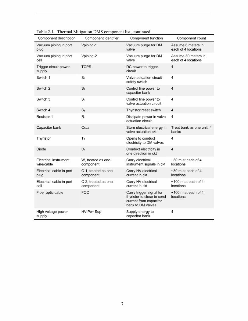
The gas reservoir in one gas holding valve is 1 liter volume and is charged to 40 bar when the DMS is prepared for operation. The design calls for four thermal mitigation MGI valve assemblies to be located in upper port plugs, and two runaway electron valve assemblies to be located in the equatorial port plugs. There are two runaway electron systems, the runaway electron suppression system (RES) mentioned above and the runaway electron dissipation system (RED). The RES and RED valves can have staggered valve actuation to enhance their effectiveness. The RES and RED are located in the same equatorial port plug. The thermal mitigation MGI valves will be instantaneously triggered from signals from the tokamak diagnostics system via the Central Interlock System, they will inject gas within 5 ms. Figure 2-1 shows the components in the thermal mitigation DMS. Figure 2-2 shows the expected position of a DM valve in a port plug. Figure 2-3 shows the DM valve actuation circuit (trigger electronics) layout. Figure 2-4 shows a cutaway of a DM valve. Table 2-1 lists the components in the TM MGI DMS.
The MGI DMS is allowed 3 hours to reset after an actuation, so compressors taking feed from the Gas Distribution System can recharge all DM valves with the correct gas mixture and 40 bar pressure. As shown in Figure 2-1, the deuterium compressor and gas metering valves are in the port cell rather than the port plug. The other gas compressors are outside the port cell, feeding in the resupply gas via small diameter piping. The three-hour time also allows trickle charge of the capacitor banks that provide energy to open the DM valves (Baylor, 2012).

4
Figure 2-1. Flow schematic diagram of a single thermal mitigation DMS valve (Baylor, 2012).
Figure 2-2. Location of a thermal mitigation DMS valve in an upper port plug (Baylor, 2012).

5
Figure 2-3. Sketch of the Fast Valve Triggering Electronic System (Baylor, 2012).
Figure 2-4. MGI DM valve concept for ITER (Baylor, 2013).

6
Table 2-1. Thermal Mitigation DMS component list.
Component description Component identifier Component function Component count
Argon and Neon compressor, type unknown, assume low or no oil type (perhaps a diaphragm compressor)
Comp-1 Compress Ar, Ne to 40 bar to charge the DMS valves
4
Argon and Neon pressure regulator
Reg-1 Regulate Ar, Ne gas pressure for DMS valve closure volume
4
Gas valve near regulator, assume motor operated valve
Valve-1 Isolates pressure regulator, routes gas to DMS valve closure volume
4
Pressure element or sensor in Ar-Ne gas line
PS-1 Monitor gas pressure 4
Gas valve in series from regulator, assume motor operated valve
Valve-2 Isolates pressure regulator and PS-1, routes gas to DMS valve closure volume
4
Deuterium compressor, type unknown, assume low or no oil type (perhaps a diaphragm compressor).
Comp-2 Compress D2 gas to 40 bar to charge the DMS valves
4
Gas metering device (assume mass flow controller)
Meter-1 Provide gas to DMS valve 1-liter chamber
4
Gas valve near meter, assume motor operated valve
Valve-3 Isolates gas meter line from vacuum line and DMS valve
4
Gas valve in vacuum line, assume motor operated valve
Valve-4 Isolates vacuum line 4
Pressure element or sensor in vacuum line
PS-2 Monitor vacuum level 4
Gas valve in series from gas metering
Valve-5 Isolates DMS valve from metering and vacuum lines
4
Pressure sensor in Ar-Ne-D2 line
PS-3 Monitor line pressure to DMS valves
4
DMS valve DM-1 The gas reservoir valve that delivers MGI to the plasma
4
Gas piping in port plug Piping-1, treated as one component
Small diameter pipe that routes gases in the port plug
Assume 6 meters in each of 4 locations
Gas piping in port cell Piping-2, treated as one component
Small diameter pipe that routes gases in the port cell
Assume 30 meters in each of 4 locations
7
Table 2-1. Thermal Mitigation DMS component list, continued.
Component description Component identifier Component function Component count
Vacuum piping in port plug
Vpiping-1 Vacuum purge for DM valve
Assume 6 meters in each of 4 locations
Vacuum piping in port cell
Vpiping-2 Vacuum purge for DM valve
Assume 30 meters in each of 4 locations
Trigger circuit power supply
TCPS DC power to trigger circuit
4
Switch 1 S1 Valve actuation circuit safety switch
4
Switch 2 S2 Control line power to capacitor bank
4
Switch 3 S3 Control line power to valve actuation circuit
4
Switch 4 S4 Thyristor reset switch 4
Resistor 1 R1 Dissipate power in valve actuation circuit
4
Capacitor bank CBank Store electrical energy in valve actuation ckt
Treat bank as one unit, 4 banks
Thyristor T1 Opens to conduct electricity to DM valves
4
Diode D1 Conduct electricity in one direction in ckt
4
Electrical instrument wire/cable
W, treated as one component
Carry electrical instrument signals in ckt
~30 m at each of 4 locations
Electrical cable in port plug
C-1, treated as one component
Carry HV electrical current in ckt
~30 m at each of 4 locations
Electrical cable in port cell
C-2, treated as one component
Carry HV electrical current in ckt
~100 m at each of 4 locations
Fiber optic cable FOC Carry trigger signal for thyristor to close to send current from capacitor bank to DM valves
~100 m at each of 4 locations
High voltage power supply
HV Pwr Sup Supply energy to capacitor bank
4

8
2.2 DMS Operation
ITER plans to conduct on the order of ~3,000 plasma pulses in a year. The DMS is armed to operate for each physics-type plasma pulse that is part of an operating session. The low power pulses performed for machine cleaning, testing and calibration, etc., in the third shift of an operating day do not require the DMS. Figures 2-1 and 2-2 show the thermal mitigation system schematic and the position of the thermal mitigation valve near the plasma periphery. The DMS is actuated by plasma diagnostics that send signals to the Central Interlock System, which gives an actuation signal to the trigger circuit shown in Figure 2-3. The MGI increases the electron density up to a critical value to completely suppress runaway electron avalanche amplification (RPrS, 2011).
It has been stated in ITER design work that plasma disruptions are part of normal operational events. Type I disruptions of ~0.4 GJ thermal energy and ~0.35 GJ of magnetic energy with a current quench of 54 ms and initial plasma current of 15 MA would occur 3,000 times during the life of ITER (GSSR, 2001). Type II disruptions would be worst case, fast disruptions with current quench time of 27 ms and 300 of these would be expected over ITER lifetime (GSSR, 2001). The ITER operating scenario is anticipated to be two or three shift plasma operation in 11 days + 3 day maintenance outage, so 2 weeks for a plasma operation session (Blackler, 2011). In 16 months, there would be 34 such 2-week sessions, then an 8 month long maintenance outage. Assuming one plasma pulse of 400 seconds requires 1-hour of machine countdown, preparation, pulse, and recovery time, and 2-shift operation, then for 2 shifts (16 h/day) ITER could accomplish (16 h/day)(11 days/session)(1 pulse/h)(34 sessions/2 years) or 2992 pulses per year on average. If ITER operates for 20 years, then there will be a total of ~60,000 plasma pulses. (Type I + Type II disruptions)/total pulses is 3,300/60,000 = 5.5% of plasma pulses end in some form of disruption, so the DMS may be actuated fairly often throughout an ITER operating year. Using the average 2992 pulses/year, then perhaps 165 pulses will end with a demand to actuate the DMS. While every other year has an 8-month outage, the average is 17 plasma sessions in a year, so the DMS actuates to discharge its pressurized gas into the vessel at the end of each plasma operating session.
The DMS is turned off for ITER long-term and short-term maintenance sessions (Maruyama, 2013). The DMS is operational during plasma operations and during ITER testing; it does not need to be operational for wall conditioning pulses. The DM system can be discharged into the vacuum vessel or it is purged via the vacuum line when it is de-armed (shut down) for ITER outages. If ITER enters a short-term maintenance in the third shift of an operating day, then presumably the system is discharged so that it is in safe mode.
To charge the system, the compressor operates, taking argon and neon gas feed from the piped gas supply systems in the ITER plant. The lines are pressurized to 40 bar and the gas is routed through the gas metering device to the DM valve 1-liter reservoir and to the DM valve plenum for cushioning the plunger that opens the valve. Once charged, the DM valve gas inlet is closed and the valve is in readiness with pressure in the 1-liter reservoir and in the plunger plenum. The capacitor bank is charged with stored electrical energy from a high voltage power supply, this energy will flow to the DM valve when a signal is received. After a signal from the Central Interlock System, the thyristor closes and electrical energy from the capacitor bank flows to a coil in the valve, and the plunger moves under the action of the eddy current electromagnetic force created by the coil. The plunger movement starts the valve opening and the gas pressure in the valve reservoir assists in opening the valve further. Then gas in the DM valve reservoir flows out a 25-mm diameter, ~1 m-long line to the plasma edge.

9
The TM portion of the DM system is modeled here. The four TM locations each have their own argon-neon compressor, as described in Table 2-1. The TM system is very similar to the RES, although the RES may have fewer gas handling valves overall than the four stand-alone subsystems of the TM system shown in Figure 2-1.
The environmental conditions in the port plug and in the port cell room where the system components reside are given in Table 2-2.
Table 2-2. Normal Environmental Conditions for DM System Areas.
Area Normal Conditions (Ciattaglia, 2012)
Port plug Pressure: 1E-04 to 1E-07 Pa
Temperature: ~120 C
Humidity: n/a, vacuum conditions
Radiation: ~1E+11 n/cm2-s (14-MeV neutrons),
~1E+13 n/cm2-s (0.1 MeV neutrons),
~1E+13 gamma/cm2-s (from NAR, 2004)
Magnetic field: > 150 mT to 3.5 T
Equatorial and Upper port cells Pressure: 140 Pa below atmospheric pressure
Temperature: 5 to 35 C
Humidity: < 60% relative humidity
Radiation dose rate: 1.44E-03 Sv/h
Magnetic field: 150 to 45 mT
2.3 Related Operating Experiences Supporting the FMEA
The literature was searched for any applicable MGI uses. The prototype systems at the DIII-D, Mega-Ampere Spherical Torus (MAST), and Alcator C-MOD machines were reviewed for any operating experience data. The published discussions dwelt on the physics aspects of MGI and the efficacy of the systems in reducing disruption damage, not the engineering aspects of system operation. The Alcator system was qualitatively described as very reproducible, in terms of timing and amount of gas delivered (Granetz, 2006). The system was stated to be benign, posing no difficulties with breakdown or current ramp up on subsequent discharges, and also the gas jet operation was very reliable. Lehnan (2011) did not address operating experiences of the DM valve system on the JET experiment, he addressed the results of gas jetting into the vacuum vessel at the plasma periphery. Kruezi (2009) mentioned that the gas valves worked reliably on JET, so presumably this means that the gas system and valves functioned when they should and did not spuriously function to prematurely terminate a plasma shot.
Baylor (2013a) had collected engineering information about the operation of similar valves in use from the set of tokamaks listed above. These data are given in Table 2-3.
Sonato (1993) reported on a gas handling system connected to a reversed field pinch experiment (RFX). The gas handling system included hydrogen, deuterium, and helium gas for experiments (Bonizzoni, 1990), oxygen and noble gases for intentional impurity introduction, methane to carbonize the metal walls, and nitrogen to bring the vessel up to atmospheric pressure. The gas transfer system was plumbed from the gas bottle room to the experiment; it supplied fuel and other gases to the experiment. Programmable logic controllers (PLCs) controlled the system operations. The PLCs are part of the experiment’s control and data acquisition system.

10
Table 2-3. DM valve operations experience from existing tokamaks.
Fusion experiment
Number of DM valves
Type of DM valves
Number of valve
failures
Number of valve
operations
Operating pressure
(Bar)
Valve seat leak rate (Pa-
m3/s) Comments
TEXTOR 2 Eddy current
1 ~200 1 to 30 1E-06 (helium)
Top valve, external leak due to coil feed-through. Changed design.
JET 1 (second valve to
be added in
October 2013)
Eddy current
0 203 2 to 36 1E-06 (helium)
Small external leak of system, no valve failure in 2008-2013. Also, JET has a 2.5 T magnetic field.
DIII-D 6 Solenoid 1 500 40 to 60 1E-06 or less
Valve seat stuck in holder, assembled incorrectly
Alcator C-MOD
2 Solenoid 0 200 40 to 60 1E-06 or less
Same valve design as DIII-D
Tore Supra
1 Solenoid 0 200 - 1E-08 Some valve leakage required firing valve to seal Teflon o-ring seal.
ASDEX Upgrade
2 Solenoid 0 10,000 5 to 12 1E-09 Viton seal maintained once per year (~1000 shots) for 10 years.
KSTAR 1 Solenoid 0 ~50 40 to 50 1.4E-11
The two most similar valves are from TEXTOR and JET, so 1 failure, and (2 valves•200 actuations)+(1 valve•203 actuations) gives a point estimate = 1/(400+203) or = 1.66E-03 per valve actuation demand. The spurious operation failure mode calculation: assuming 1 actuation per 8-h pulse day, and no spurious operations listed in the table, then = 0.5/T (Atwood, 2003), where T is the total unit hours of operation. Then 0.5/(2 valves•200 actuations•8 h/actuation)+(1 valve•203 actuations•8 h/actuation) ~ 1E-04/valve-hour. There were no valve plugging events reported, so the same 1E-04/valve-hour applies to the plugging failure mode.
Standard industrial components that operate in non-standard environments were tested to assure operability and reliability in the new environment. For specialty components, several tests were performed: magnetic permeability, dimensional tests, cleaning procedures were tested, pressure test, component leak rate and integral leak rate tests. The gas lines had a maximum pressure of 2 bar, so they were tested at 4 bar absolute for 10 minutes, then the lines were evacuated. This was repeated four times for the leak test. The system had to operate in the

11
presence of magnetic fields, which induce voltages and currents along the metallic piping. These induced energies can lead to arcs and overheating. Magnetic forces are generated in ferromagnetic parts. The magnetic circuits of electromechanical devices can be saturated as well. The RFX used ceramic and polytetrafluoroethylene (e.g., Teflon) vacuum insulators in the metal piping to prevent loop currents. Gas valves were electro-pneumatic, and had a response to magnetic fields. These valves used a solenoid to control the motive-power gas flow to the valve actuator. In a magnetic field parallel to the axis of the coil, there was interference. In a range of 20 mT to 45 mT, the field created in the solenoid was reduced and valve operation was compromised. With this knowledge from testing, the valves were placed with the solenoid axis orthogonal to the magnetic field direction, making the threshold magnetic field value to affect the valves over 100 mT. For those gas valves that had to operate close to the RFX, in greater than 100 mT zones, a two-layer soft iron magnetic shield was designed to protect the solenoid coil. The gas handling system functioned well during testing, followed by an extensive machine commissioning period, and the system also gave 100% availability in the first year of RFX operation.
Yang (2010) discussed the ITER fuel gas injection system. Noteworthy challenges are high gamma radiation and magnetic field exposure (~200 mT) for the flow control valves. Mass flow controllers might be used if they can be placed in magnetic shields to reduce their magnetic field exposure.
Childs (1993) discussed the gas delivery system for the Alcator C-Mod tokamak. The system functioned well, even when there were power outages that would shut the system down. When de-powered the system de-energizes to a safe state.
Villaran (1990) discussed power plant instrument air systems, which are designed to provide a reliable, high quality air supply for plant uses, including breathing air, instrumentation, and testing needs. Villaran also discussed failure causes and mechanisms in these systems, which is of interest for the FMEA of the DM system. Moisture in air, particulates in the vents, and hydrocarbon contamination have caused a considerable number of air system failures. Filters were degraded by moisture, dust, particulates from the system (corrosion from piping, weld beads or slag, etc.). System instrument air lines were clogged by hydrocarbons, dirt, moisture – which caused faulty indication and erroneous control signals in those systems. Oil leaks led to hydrocarbons on valve seals, causing the seals to become brittle and stick to mating surfaces. Seal disintegration led to particulate from the seals spreading in the system. Rust in the piping and equipment caused by moisture in the gas has been dislodged in severe vibration events (flow-induced pressure pulsations, or equipment induced vibration), causing problems with valve seats. Polymeric seals in accumulator tanks and compressors degrade with time and have leaked gas to the room atmosphere. Given the importance of impurities in these systems, it should be noted that cleanliness in the gas supply and the DM pipework must be established not only for reliable system operation but also to preclude ingress of impurities into the vacuum vessel. Impurities could be incompatible with maintaining vacuum or could react with in-vessel materials. Granted, the ~28 liters of gas in the MGI DM system are few compared to the ~800 m3 vacuum vessel and impurities could be measured in the ppm range within the 28 liters, but cleanliness remains an important issue since the DM system could be actuated more than 165 times in a year. Finken (2001) discussed that the injection gases themselves have had effects on the next plasma pulse at TEXTOR. Injecting large amounts of hydrogen isotopes at TEXTOR generally load onto the walls so that special measures must be taken to release the gas stored in and on the walls. Heavier impurities may show up in the startup phase of the next plasma pulse and lead to poor performance of the pulse. However, it is noted that TEXTOR (major radius of 1.75 m) is not

12
nearly as large a machine as ITER, and the ITER DM designers are confident that the liters of gas injected for a mitigation will not spoil the following plasma pulses (Lyttle, 2013).
Gray (1969) discussed the Dragon fission reactor helium cooling system operating experiences. Some of the Dragon valves showed sticking behavior of metal valve disks to metal seats when they were opened after remaining closed for long periods of time. The valves exhibiting sticking phenomena were modified so the motor operators on these valves would deliver a shock when opening to break the metal-metal contact. There were no problems with valve ‘sticking’ after that modification. Since the DM gas valve uses a vespel seal rather than metal-on-metal, this type of “sticking” failure event should not be an issue for the DM system.
2.4 FMEA Failure Rate Data
The component failure rate data used in the FMEA came from several sources. The ITER Project has an approved component failure rate database, but the database typically addresses larger components than 1-liter gas volumes, and piping larger than the tubing used in this system (less than 25-mm diameter). There are data sources for gas pipelines (ambient temperature, ~600 to 1000 psig natural gas) used in the commercial energy industry but these components also vary widely from the system of interest. Data was found from published data sources believed to be most applicable to the DM components. Adjustments were made to account for the environment of the location where the DM system resides. Data sources for components of medium pressure compressed air and gas systems included Blanton (1998) and Hale (2001). Other data sources included Denson (1996), Dexter (1982), Mahar (2011), and Volotinen (1999). Failure rate data source citations found in the FMEA table pages in Appendix A are cited in the references section of this chapter.
Information discussed in section 2.2 allows calculation of DM system demands per year, which is important for the DM valves and the other equipment that must start or function on demand. On average there are an estimated 165 disrupting pulses per year, and an assumed 17 operator discharges of the DM system at the end of 2-week pulse sessions, or 182 actuations. There may be other discharges actuated from the control room during the two-week campaigns to ‘safe’ the system if there is short-term maintenance to be conducted in the third shift of the day. As a first estimate of such pulses, another 18 discharges are assumed as ~10% of third shift count in a year. Therefore, the total is 200 system actuations/year – this is about 1 actuation per operating day. ITER will operate on average for 2,992 hours or roughly 3,000 hours each calendar year. These system demand and operating hour values will be used with the failure rate data listed in Appendix A to determine the annual probability of failure, which will set the occurrence (the O value) of the criticality value.
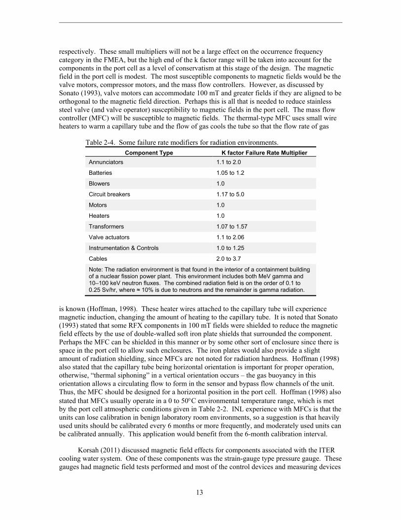
The aggressive environments of the port cell and the port plug must be accounted for. Table 2-2 gave the normal operating environments for these two areas. The port cell is not very different from a fission reactor containment building conditions. The fission reactor containment building averages 39.7°C (103.5°F) (Guyer, 1982). The air pressure and humidity in the fission reactor containment building are not greatly different than atmospheric conditions. The fission containment pressure typically tends to vary between 1070 and 960 mbar (Dey, 1995). The radiation conditions in a fission reactor containment building are 20-year neutron fluences of 1E+13 to 1E+14 n/cm2, and gamma fluences of 1E+15 to 1E+19 gamma/cm2 (Cadwallader, 2013). Some failure rate multipliers for the fission reactor containment building environment are given in Table 2-4 below (Cadwallader, 2013). It is noted that these k factor multipliers reported for the containment building environment tend to be modest values. For blowers and motors, the k factor was 1. For transformers and valve actuators the values vary from 1 to 1.57 and 1 to 2.06,
13
respectively. These small multipliers will not be a large effect on the occurrence frequency category in the FMEA, but the high end of the k factor range will be taken into account for the components in the port cell as a level of conservatism at this stage of the design. The magnetic field in the port cell is modest. The most susceptible components to magnetic fields would be the valve motors, compressor motors, and the mass flow controllers. However, as discussed by Sonato (1993), valve motors can accommodate 100 mT and greater fields if they are aligned to be orthogonal to the magnetic field direction. Perhaps this is all that is needed to reduce stainless steel valve (and valve operator) susceptibility to magnetic fields in the port cell. The mass flow controller (MFC) will be susceptible to magnetic fields. The thermal-type MFC uses small wire heaters to warm a capillary tube and the flow of gas cools the tube so that the flow rate of gas
Table 2-4. Some failure rate modifiers for radiation environments.
Component Type K factor Failure Rate Multiplier
Annunciators 1.1 to 2.0
Batteries 1.05 to 1.2
Blowers 1.0
Circuit breakers 1.17 to 5.0
Motors 1.0
Heaters 1.0
Transformers 1.07 to 1.57
Valve actuators 1.1 to 2.06
Instrumentation & Controls 1.0 to 1.25
Cables 2.0 to 3.7
Note: The radiation environment is that found in the interior of a containment building of a nuclear fission power plant. This environment includes both MeV gamma and 10–100 keV neutron fluxes. The combined radiation field is on the order of 0.1 to 0.25 Sv/hr, where ≈ 10% is due to neutrons and the remainder is gamma radiation.
is known (Hoffman, 1998). These heater wires attached to the capillary tube will experience magnetic induction, changing the amount of heating to the capillary tube. It is noted that Sonato (1993) stated that some RFX components in 100 mT fields were shielded to reduce the magnetic field effects by the use of double-walled soft iron plate shields that surrounded the component. Perhaps the MFC can be shielded in this manner or by some other sort of enclosure since there is space in the port cell to allow such enclosures. The iron plates would also provide a slight amount of radiation shielding, since MFCs are not noted for radiation hardness. Hoffman (1998) also stated that the capillary tube being horizontal orientation is important for proper operation, otherwise, “thermal siphoning” in a vertical orientation occurs – the gas buoyancy in this orientation allows a circulating flow to form in the sensor and bypass flow channels of the unit. Thus, the MFC should be designed for a horizontal position in the port cell. Hoffman (1998) also stated that MFCs usually operate in a 0 to 50C environmental temperature range, which is met by the port cell atmospheric conditions given in Table 2-2. INL experience with MFCs is that the units can lose calibration in benign laboratory room environments, so a suggestion is that heavily used units should be calibrated every 6 months or more frequently, and moderately used units can be calibrated annually. This application would benefit from the 6-month calibration interval.
Korsah (2011) discussed magnetic field effects for components associated with the ITER cooling water system. One of these components was the strain-gauge type pressure gauge. These gauges had magnetic field tests performed and most of the control devices and measuring devices
14
experienced magnetic susceptibility in the 5 to 20 mT range. The type of pressure sensor to be used in the DM system is not identified, but there is the possibility of magnetic field susceptibility. The port cells, as noted in Table 2-2, will be in the 45 to 150 mT range, so it is assumed that the design will call for shielding enclosures around each of the three pressure instruments located in the port cell if the selected sensor exhibits susceptibility to magnetic fields. For the component failure rate, it is assumed that the pressure sensors are not under the influence of magnetic fields.
For components in the port plug, Table 2-2 showed that the operating environment is much more severe – high temperature, vacuum, high radiation, and high magnetic field. The designers chose wisely to place passive components in the port plug, leaving the active components in the milder conditions of the port cell. The DM system valve and pipework in the port cell are more passive-type components that can tolerate the high temperature and vacuum conditions without requiring a k factor. Radiation damage to stainless steel was addressed in work done for stainless steel piping sheaths for in-vessel magnet coils (Cadwallader, 2013). In-vessel conditions are more severe than those in the port plug, but for conservatism at this stage of the DM design the in-vessel stainless steel sheath value of 1.7E-08/hour-meter for small diameter (58 mm) pipe breach/leakage will be applied to the gas supply piping and vacuum piping that is routed to the DM valve in the port plug. This value was based on fast fission reactor core radiation exposure, so it is greater than the exposure in the port plug. Taking guidance from Blanchard (1998) the rupture failure rate is (1.7E-08/h-m)/30 or 5.7E-10/h-m, and plugging of the gas piping would be the same value as the rupture failure mode at 5.7E-10/h-m. The line length in the port plug to the DM valve is estimated to be ~ 6 m, and the exhaust line is ~1 m. The 1.7E-08/h-m failure rate was calculated for 150°C, which is close to the port plug operating temperature of 120C. No k factor is needed to adjust the failure rate for high temperature.
The DM valve itself is built of austenitic stainless steel for the valve body and it uses an aluminum plunger with a vespel polyimide seal. The electrical coil that drives the plunger accepts high electrical energy from the capacitor bank when actuated. Fortunately, actuations are low frequency (~1/day) for this gas valve, so there is time for heat conduction to dissipate the heat that is generated by current in the coil when the DM valve is actuated. This valve is in a 3.5 Tesla magnetic field and a high temperature, low pressure, high radiation environment as defined in Table 2-2. The stainless steel could exhibit some increased magnetic permeability due to forming, welding, machining, cold work, etc., but this is difficult to quantify. Attaya (1984) discussed magnetic field effects of 3 T fields on HT-9 (a 12% chromium and 1% molybdenum ferritic stainless steel) coolant piping. Attaya found that the magnetic forces on these ferromagnetic pipes were small compared to the coolant pressure (the coolant was lead-lithium, so the pressure was perhaps 3 or 4 bar, not nearly as high as in water coolant applications of up to 140 bar). Assuming that the HT-9 ferromagnetic steel results are an upper bound for austenitic stainless steel, then qualitatively the magnetic forces on the DM valve will be much less than those described by Attaya – and Attaya’s magnetic forces were small compared to the coolant pressure forces. Therefore, as a first approximation, the magnetic field effects on the valve body, plunger, and seal are not significant. The valve coil may be susceptible since 3.5 T is a high magnetic field. Coil orientation will not reduce the effects of such a strong field, so the electrical energy surge into the coil is large to overcome any magnetic-field-induced energy created in the coil. The assumption is this coil is built to withstand the magnetic field. Typically, reliability discussions for electrical devices employing coils include the concept that increasing the temperature above the rated operating temperature causes premature failure of the insulation around the coil, leading to short circuit and even fire. Hubert (2003) described the “ten-degree half-life” rule, where the insulation life expectancy is decreased by half with each sustained duration operating session at 10C above the normal operating temperature. The DM valve coil

15
will be built with the 120C environmental temperature and vacuum (no gas convection to cool the coil) as design requirements. And, if there was a short circuit, the 1E-04 Pa or lower pressure environment means there is greatly reduced oxygen present, so fire could not propagate in the coil or valve body.
The DM valve uses a vespel polyimide valve stem seat. Vespel has been tested and can accommodate up to 325C operating temperature (Murari, 2004), so there is no temperature correction factor necessary. Vespel will undergo isotopic exchange with tritium even at room temperature (Clark, 2007). This effect needs to be investigated for any degradations to the vespel since there will be hundreds of grams of tritium in various states (adsorbed and absorbed on materials, free gas, constituent of gas molecules, etc.) in the ITER vessel. Also, the typical operating environment for the vespel is that the valve outlet line to the ITER vessel is under high vacuum, but if the vessel suffers a water leak then the vespel could be exposed to a steam environment. A literature search was conducted but no data were found on vespel degradation due to steam exposure at any temperature. This effect should be investigated to determine if the valve stem seals would be degraded by an ITER accident event. Polyimides like vespel are reputed to be radiation resistant, in the 1E+07 to 1E+09 Grays (Bruce, 1981), and vespel showed very little change in its material properties at 3E+07 Grays (Tavlet, 1998). Given this information, there is no radiation damage k factor estimated for the valve seal. It is noted that vespel has been used as a valve seat seal in gas systems at the Joint European Torus with success; the researchers there tested vespel valve stem tips for stainless steel gas valves to 50,000 open-close cycles of the valves and there was no detectable gas leak across the valve seat (Hemmerich, 1989); the vespel seal valves also gave good service over several years (Hemmerich, 1992). Using the reported test data to apply to the DM valve, an estimate of 200 demands/3,000 hours is used. With the failure rate formula from Atwood (2003), this gives =0.5/(50,000 cycle demands3000 h/200 demands) or ~7E-07/hour as a first estimate of the failure rate for a stainless steel valve with vespel seal leaking past the seat. Following guidance from Blanchard (1998) the seal rupture failure rate should be 20 times less at 3.5E-08/hour. There is also a bellows along the plunger shaft to keep the valve closure plenum separate from the valve injection gas reservoir. There are no compiled operating experience data on irradiated bellows. Typically, bellows life is given by the rated number of compression-extension cycles the unit can withstand before fatigue or other failure. This value is at present not known for the bellows. Assuming that the typical industrial design practice of specifying additional cycle life margin for these units is done, then handbook data will be applied to the bellows. Cherry (2001) stated that stainless steel bellows should function well up to a radiation threshold of 1E+19 n/cm2 where neutrons begin to effect metals. Using Table 2-2, the bellows would be two times that threshold fluence at the end of a 20-year life; however, ITER will not operate at high fluence for its entire lifetime. At this time, a bellows failure rate from industrial operations will be used without modifiers. A ‘ground fixed’ all-modes failure rate for bellows is 4.3E-06/h (Mahar, 2011). Failure mode distributions are given by Fields (2012). For bellows, 33.3% is mechanical failure, 33.3% is described as worn (which is very close to mechanical failure), 27.8% is induced failure (workers damage, cut or puncture the bellows), and 5.6% is unknown failure. Assuming thorough inspection of the bellows when installed in the valve and careful handling to install the valve in the port plug, then the 27.8% can be removed, leaving 3.1E-06/h for bellows leakage. A factor of 10 reduction in that value is assumed (see Eide, 1991) to quantify the rupture failure mode. To address the valve body failure modes of leak and rupture to the port plug, it is noted that this valve is a special design, the valve is a cylinder shape like a pipe and it is constructed of reasonably thick-walled stainless steel. Therefore, a stainless steel pipe section (assume 0.5-meter length and 150 mm diameter, and 7.11 mm wall thickness) will be used to obtain estimates of the valve body failure mode of leakage. Borrowing data from Cadwallader (2013), high irradiation stainless steel tubing of small size at ~150°C is a failure rate of 1.5E-08/h-m. From Cadwallader (2013) a k factor to
16
adjust for size is (3.66 mm)(7.11 mm)2/(150 mm)(0.3 mm)2 or 13.7. Therefore, the leakage failure rate would be (0.5 m)(2E-07/h-m)=1E-07/h. Rupture would be at least a factor of ten reduction (see Eide, 1991), or a failure rate of 1E-08/h.
The thyristor is an important part of the trigger circuit. Most thyristor reliability data is hourly operation rather than transferring from off to on or vice versa. Reviewing the literature, data from Alcator C-MOD (Fairfax, 1993) has given this information: twelve thyristor units in the poloidal field coil power system, operating at 4 kV and 50 kA, operated over 1000 plasma shot demands with only a few failures (some fuses opened, they were changed out to higher ratings). Assuming that ‘a few’ means 3 failures, then a demand failure rate for thyristors to change from off to on is 3 failures/(12 units•1,000 demands) = 2.5E-04/thyristor-demand. It is noted that the Alcator machine does not create high neutron fluence, and the operating environment is that of an industrial building. Therefore, this value is modified with a k factor of 1.25 to account for the port cell environment, giving 3.125E-04/thyristor-demand.
2.5 MGI DM Preliminary FMEA
The MGI DM system FMEA covered the system schematic diagrams shown in Figures 2-1 and 2-3. The pressurized “armed” operating mode during plasma pulses was treated. This was chosen based on the idea that ITER could wait in standby to begin a campaign if the DM system was not able to pressurize (also referred to as charge) its gas reservoirs during machine preparations for pulsing.
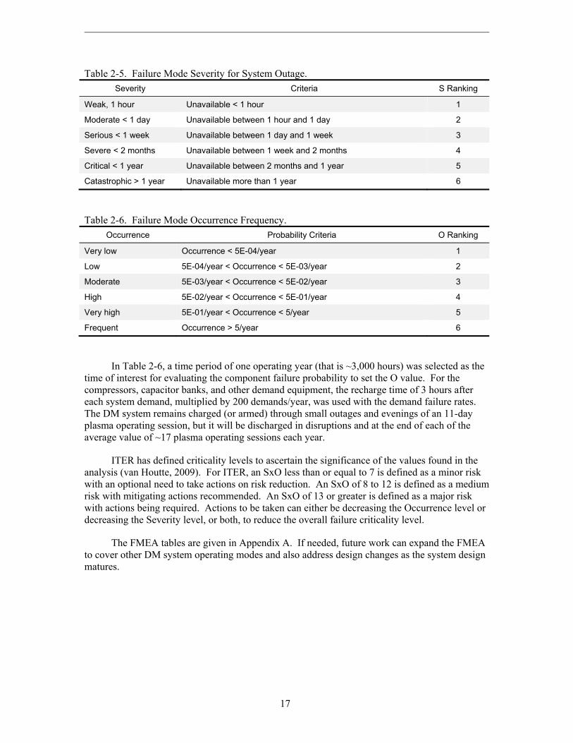
Many FMEAs use the risk priority number (RPN) approach given in IEC 60812 (IEC, 2006) to describe the criticality or importance of each component failure mode as given in the analysis. The RPN is the product of three values, S, the severity of the failure, O, the occurrence frequency of the failure, and D, the detection of the failure. Therefore, RPN=S•O•D. Assigning numerical values to S, O, and D is semi-subjective. It is noted that the ITER project has defined the criticality of a failure as the product of only S•O. The qualitative values 1 through 6 were defined to use for S and O so that criticality can be calculated. Tables 2-5 and 2-6 below show criteria for assigning S and O numerical values (van Houtte, 2009). For this analysis, it is assumed that any portion of the MGI system is necessary (that is, 100% system operation for success) so that any component fault or failure that requires repair is affecting the entire system, and the individual component repair time affects the entire system availability. As the system design matures, system success criteria will be better defined and this assumption can be revisited. It is also noted that the ITER Project Requirements state that personnel entry into the port cells for hands-on maintenance should allow decay time for the radiation dose rate to decrease to 100Sv/h. This radiological safety hold time was estimated to be 12 days (Chiocchio, 2010). Thus, any entry into the port cell for repair is estimated to take the repair time plus 12 days. The 12 days was not accounted for in the FMEA since all failure severities would have been S=4 due to the ranking scheme and the fact that most repair times are measured in hours. Fixing S=4 would not have allowed any insight to failure criticality of the system components.
17
Table 2-5. Failure Mode Severity for System Outage.
Severity Criteria S Ranking
Weak, 1 hour Unavailable < 1 hour 1
Moderate < 1 day Unavailable between 1 hour and 1 day 2
Serious < 1 week Unavailable between 1 day and 1 week 3
Severe < 2 months Unavailable between 1 week and 2 months 4
Critical < 1 year Unavailable between 2 months and 1 year 5
Catastrophic > 1 year Unavailable more than 1 year 6
Table 2-6. Failure Mode Occurrence Frequency.
Occurrence Probability Criteria O Ranking
Very low Occurrence < 5E-04/year 1
Low 5E-04/year < Occurrence < 5E-03/year 2
Moderate 5E-03/year < Occurrence < 5E-02/year 3
High 5E-02/year < Occurrence < 5E-01/year 4
Very high 5E-01/year < Occurrence < 5/year 5
Frequent Occurrence > 5/year 6
In Table 2-6, a time period of one operating year (that is ~3,000 hours) was selected as the time of interest for evaluating the component failure probability to set the O value. For the compressors, capacitor banks, and other demand equipment, the recharge time of 3 hours after each system demand, multiplied by 200 demands/year, was used with the demand failure rates. The DM system remains charged (or armed) through small outages and evenings of an 11-day plasma operating session, but it will be discharged in disruptions and at the end of each of the average value of ~17 plasma operating sessions each year.
ITER has defined criticality levels to ascertain the significance of the values found in the analysis (van Houtte, 2009). For ITER, an SxO less than or equal to 7 is defined as a minor risk with an optional need to take actions on risk reduction. An SxO of 8 to 12 is defined as a medium risk with mitigating actions recommended. An SxO of 13 or greater is defined as a major risk with actions being required. Actions to be taken can either be decreasing the Occurrence level or decreasing the Severity level, or both, to reduce the overall failure criticality level.
The FMEA tables are given in Appendix A. If needed, future work can expand the FMEA to cover other DM system operating modes and also address design changes as the system design matures.
18
2.6 References
Air Liquide, 2010. Design and Safety Handbook for Specialty Gas Delivery Systems, 5th edition, Air Liquide America Specialty Gases LLC, Plumsteadville, Pennsylvania, 2010.
ANSI, 2010. Flammability Characteristics of Combustible Gases and Vapors, ANSI/ISA-TR-12-13-01-1999, American National Standards Institute, reaffirmed 2010.
Attaya, 1984. H. Attaya, G. L. Kulcinski, and W. G. Wolfer, “Analysis of Forces on Ferromagnetic Components Used in Magnetic Fusion Reactors,” Journal of Nuclear Materials, 122-123 (1984) 96-100.
Atwood, 2003. C. L. Atwood et al., Handbook of Parameter Estimation for Probabilistic Risk Assessment, NUREG/CR-6823, Nuclear Regulatory Commission, Washington, DC (2003), chapter 6.
Baylor, 2012. L. Baylor, Conceptual Design Description Document for the DMS ORNL Massive Gas Injection System, ITER IDM DCQYNS, December 1, 2012.
Baylor, 2013. L. R. Baylor, S. K. Combs, N. Commaux, P. W. Fisher, S. J. Meitner, M. Lyttle, D. A. Rasmussen, and S. Maruyama, “ITER Disruption Mitigation System Conceptual Design Review Highlights – Options for ITER,” Oak Ridge National Laboratory, powerpoint presentation to the US Virtual Laboratory for Technology monthly conference call, January 16, 2013.
Baylor, 2013a. L. R. Baylor, Oak Ridge National Laboratory, e-mail communication of disruption valve operating experience data, August 27, 2013.
Beck, 2011. J. M. Beck, L. F. Pincock, High Temperature Gas-Cooled Reactors Lessons Learned Applicable to the Next Generation Nuclear Plant, INL/EXT-10-19329, revision 1, Idaho National Laboratory, April 2011.
Blackler, 2011. K. Blackler, Operations Handbook – 2 Operational States, ITER IDM 2LGF8N, April 27, 2011.
Blanchard, 1998. A. Blanchard and B. N. Roy, Savannah River Site Generic Data Base Development, WSRC-TR-93-262, rev. 1, Westinghouse Savannah River Company, May 1998.
Bonizzoni, 1990. G. Bonizzoni, F. Gnesotto, P. Sonato, and S. Vittura, “The vacuum and gas inlet systems for the RFX fusion experiment,” Vacuum, 41 (1990) 1503-1507.
Bruce, 1981. M. B. Bruce, M. V. Davis, Radiation Effects on Organic Materials in Nuclear Plants, EPRI NP-2129, Electric Power Research Institute, November 1981, chapter 3.
Cadwallader, 1996. L. C. Cadwallader, Reliability Estimates for Selected Sensors in Fusion Applications, INEL-96/0295, Idaho National Engineering Laboratory, September 1996.
Cadwallader, 1999. L. C. Cadwallader, Liquid Metal, Gas, Molten Salt, and Organic Cooling System Operating Experience Review for Fusion Applications, INEEL/EXT-99-00144, Idaho National Engineering and Environmental Laboratory, February 1999.

19
Cadwallader, 2001. L. C. Cadwallader, Operating Experience Review of In-Plant Electrical Distribution Systems for Fusion Applications, INEEL/EXT-01-01558, November 2001.
Cadwallader, 2013. L. C. Cadwallader, In-Vessel Coil Material Failure Rate Estimates for ITER Design Use, INL/EXT-13-28031, Idaho National Laboratory, January 2013.
Cherry, 2001. J. L. Cherry et al., Aging Management and Performance of Stainless Steel Bellows in Nuclear Power Plants, NUREG/CR-6726, US Nuclear Regulatory Commission, May 2001, chapter 4.
Childs, 1993. R. Childs, J. Goetz, M. Graf, A. Hubbard, J. Rice and T. Toland, “Design, control and operation of the vacuum and gas systems for Alcator C-Mod,” Proceedings of the 15th IEEE/NPSS Symposium on Fusion Engineering, Hyannis, MA, October 11-15, 1993, IEEE (1994) 1051-1054.
Chiocchio, 2010. S. Chiocchio, B. De Gentile, M. Shute, Project Requirements, version 4.6, ITER IDM 27ZRW8, May 2010, section 7.3.
Ciattaglia, 2012. S. Ciattaglia, G. Cambi, Environmental Conditions Room Book, ITER IDM 2UUZ23, September 12, 2012.
Clark, 2007. E. A. Clark, K. L. Shanahan, “Effects of Tritium on UHMW-PE, PTFE, and Vespel Polyimide,” Fusion Science and Technology, 52 (2007) 1007-1011.
Denson, 1996. W. Denson, W. Crowell, P. Jaworski, D. Mahar, Electronic Parts Reliability Data 1997, EPRD-1997, Reliability Analysis Center, Rome, New York, November 1996.
Dexter, 1982. A. H. Dexter and W. C. Perkins, Component Failure-Rate Data with Potential Applicability to a Nuclear Fuel Reprocessing Plant, DP-1633, Savannah River Laboratory, July 1982.
Dey, 1995. M. Dey, L. Skoblar. P. Chen, D. Goldin, P. Cybulskis, L. Minton, S. Rose, W. Roman, Performance-Based Containment Leak-Test Program, NUREG-1493, US Nuclear Regulatory Commission, Appendix C, September 1995.
Drexel, 1996. C. F. Drexel, “Digital Mass Flow Controllers Come of Age,” Solid State Technology, volume 39, number 11 (1996) 99-106.
Eide, 1991. S. A. Eide, S. T. Khericha, M. B. Calley, D. A. Johnson, and M. L. Marteeny, Component External Leakage and Rupture Frequency Estimates, EGG-SSRE-9639, Idaho National Engineering Laboratory, November 1991.
Fairfax, 1993. S. A. Fairfax et al., “Operation of the Alcator C-MOD Power System,” Proceedings of the 15th IEEE/NPSS Symposium on Fusion Engineering, Hyannis, Massachusetts, October 11-15, 1993, IEEE (1993) p 877-880.
Fields, 2012. W. Fields, J. Reade, D. Mahar, Failure Mode/Mechanism Distributions 2013, FMD-13, Reliability Information Analysis Center, Utica, New York, December 2012.
Finken, 2001. K. H. Finken et al., “Mitigation of disruptions by fast helium gas puffs,” Nuclear Fusion, 41 (2001) 1651-1661.

20
Fricks, 1998. R. M. Fricks, K. S. Trivedi, “Availability modeling of energy management systems,” Microelectronics Reliability, 38 (1998) 727-743.
Gillen, 1990. K. T. Gillen, R. L. Clough, Predictive Aging Results for Cable Materials in Nuclear Power Plants, SAND-90-2009, Sandia National Laboratories, November 1990.
Granetz, 2006. R. Granetz et al., “Gas jet disruption mitigation studies on Alcator C-Mod,” Nuclear Fusion, 46 (2006) 1001-1008.
Gray, 1969. P. S. Gray and C. Watts, “Operating Experience with the Dragon Reactor,” paper SM-111/66, in Advanced and High-Temperature Gas-Cooled Reactors, IAEA, Vienna, 1969, pages 3-19.
GSSR, 2001. Generic Site Safety Report (GSSR), volume VII, Analysis of Reference Events, ITER document G 84 RI 6 01-07-10 R 1.0, July 2001, page VII-11.
Guyer, 1982. E. C. Guyer, D. L. Brownell, J. G. Bourne, and W. F. Lenz, Control of Containment Air Temperature: An Industry Survey and Insulation Test, EPRI NP-2694, Electric Power Research Institute, October 1982.
Hale, 2001. P. S. Hale, Jr., and R. G. Arno, “Survey of Reliability and Availability Information for Power Distribution, Power Generation, and HVAC Components for Commercial, Industrial, and Utility Installations,” ASHRAE Transactions, 107 (2001) 360-389.
Harris, 1984. A. P. Harris, Reliability and Maintainability Data for Industrial Plants, TD-84-3, A. P. Harris & Associates, Ottawa, Canada, Spring 1984.
Hourtoule, 2005. J. Hourtoule, D. van Houtte, P. Fejoz, P. Hertout, “Magnetic compatibility of
standard components for electrical installations, tests on programmable logic controllers and other electronic devices,” Fusion Engineering and Design, 75-79 (2005) 179-183.
Hemmerich, 1989. J. L. Hemmerich et al., “Key Components of the JET Active Gas Handling
System – Experimental Programme and Test Results,” Fusion Engineering and Design, 11 (1989) 93-100.
Hemmerich, 1992. J. L. Hemmerich, R. Lässer, T. Winkel, “Gas recovery system for the first
JET tritium experiment,” Fusion Engineering and Design, 19 (1992) 161-167. Hoffman, 1998. D. M. Hoffman, B. Singh, J. H. Thomas III, editors, Handbook of Vacuum
Science and Technology, Academic Publishers, San Diego, California (1998), section 3.4.2.
Hubert, 2003. C. I. Hubert, Operating, Testing, and Preventive Maintenance of Electrical Power
Apparatus, Prentice Hall Publishers, Upper Saddle River, New Jersey, 2003, section 23.6. IEC, 2006. Analysis techniques for system reliability – Procedure for failure mode and effects
analysis, IEC 60812, second edition, International Electrotechnical Commission, Geneva, Switzerland, 2006.
21
Jacobus, 1990. M. J. Jacobus, Aging of Cables, Connections, and Electrical Penetration Assemblies Used in Nuclear Power Plants, NUREG/CR-5461, US Nuclear Regulatory Commission, July 1990, page 29.
Korsah, 2011. K. Korsah, M. Smith, S. Kim, C. Neumeyer, “Options for Shielding Tokamak
Cooling Water Electrical Components against High Magnetic Fields, Proceedings of the 24th IEEE/NPSS Symposium on Fusion Engineering, Chicago, Illinois, June 26-30, 2011.
Kruezi, 2009. U. Kruezi et al., “Massive gas injection experiments at JET – performance and
characterization of the disruption mitigation valve,” Proceedings of the 36th EPS Conference on Plasma Physics, Sofia, Bulgaria, June 29-July 3, 2009, Europhysics Conference Abstracts, 33E (2009) poster P-2.153. Available at: http://epsppd.epfl.ch/Sofia/html/contents.htm.
Lehnen, 2011. M. Lehnen et al., “Disruption mitigation by massive gas injection in JET,”
Nuclear Fusion, 51 (2011) doi:10.1088/0029-5515/51/12/123010. Lyttle, 2013. M. S. Lyttle, ITER designer at Oak Ridge National Laboratory, e-mail
communication on MGI system design, August 27, 2013.
Mahar, 2011. D. Mahar et al., Nonelectronic Parts Reliability Data 2011, NPRD-2011, vol. 1, page 2-72, Reliability Information Analysis Center, Utica, New York, January 2011.
Maruyama, 2013. S. Maruyama, M. Shute, SRD-18-DM (Disruption Mitigation Systems) from DOORS, ITER IDM BEJQWA, May 3, 2013.
Merrill, 1991. B. J. Merrill and S. C. Jardin, “Coolant Ingress Induced Disruption Calculations for ITER,” Fusion Technology, 19 (1991) 1278-1283.
Murari, 2004. A. Murari, A. Barzon, “Ultra high vacuum properties of some engineering polymers,” IEEE Transactions on Dielectrics and Electrical Insulation, 11 (2004) 613-619.
NAR, 2004. Nuclear Analysis Report (NAR), ITER IDM 22F2ST, version 2, July 2004, Figure 3.2.
Paula, 1993. H. M. Paula, “Failure rates for programmable logic controllers,” Reliability Engineering and System Safety, 39 (1993) 325-328.
RPrS, 2011. Rapport Préliminaire de Sûreté, ITER IDM 3ZR2NC, version 3, Volume 1, Chapter 13, section 2.4.2, “Disruption and Runaway Electron Mitigation System R&D,” December 12, 2011.
Sonato, 1993. R. Sonato, S. Vittura, and G. Zollino, “Vacuum and gas handling systems integration in the RFX fusion experiment,” Journal of Nuclear Materials, 200 (1993) 337-342.
Tavlet, 1998. M. Tavlet, A. Fontaine, H. Schönbacher, Compilation of Radiation Damage Test Data, Part II, thermoset and thermoplastic resins, composite materials, 2nd edition, CERN 98-01, May 18, 1998.

22
van Houtte, 2009. D. van Houtte, K. Okayama, F. Sagot, ITER RAMI Analysis Program, ITER IDM 28WBXD, July 23, 2009.
Villaran, 1990. M. Villaran, R. Fullwood, M. Subudhi, Aging Assessment of Instrument Air Systems in Nuclear Power Plants, NUREG/CR-5419, US Nuclear Regulatory Commission, January 1990.
Volotinen, 1999. T. Volotinen et al., editors, Reliability of Optical Fibres and Components, Springer Verlag, London, UK, 1999, page 312.
Walker, 2011. I. R. Walker, Reliability in Scientific Research, Cambridge University Press, 2011, section 3.8,
Yang, 2010. Y. Yang, S. Maruyama, R. Pitts, M. Sugihara, W. Li, T. Jiang, B. Li, “System requirements and design challenges of the gas injection system of ITER,” Fusion Engineering and Design, 85 (2010) 2292-2294.

23
3. FMEA RESULTS
This chapter gives an overview of the results of the FMEA pages that are listed in Appendix A. Suggestions to the designers are also given in this chapter under the conclusions and recommendations section.
3.1 FMEA Results
The following tables show the results from the FMEA, starting with the major risks (criticality ≥ 13) and then the moderate risks (8 ≥ criticality ≥ 12). Major risks should be mitigated by either making changes so that the occurrence frequency decreases or the severity of the failure event decreases. Moderate risks are advised to consider mitigation. Minor risks can be tolerated in the existing design and are only listed in the tables in Appendix A.
Table 3-1. List of preliminary FMEA major risks.
Component Failure mode
Criticality
S•O=C Comments
Argon-neon compressor contamination 4x6=24 Oil and moisture contamination in gas
Deuterium compressor contamination 4x6=24 Oil and moisture contamination in gas
DM-1 valve Fails to open on demand 5x4=20 Experience data from tokamaks is small, so failure rate is high
DM-1 valve Fails to reclose 5x4=20 Experience data from tokamaks is small, so failure rate is high
DM-1 valve Internal leak 5x3=15 Criticality was driven by the repair severity.
High voltage cable in port plug
Short circuit 5x3=15 Did not have failure data for mineral insulated co-ax cable, used traditional cable data
High voltage cable in port plug
Open circuit 5x3=15 Did not have failure data for mineral insulated co-ax cable, used traditional cable data

24
Table 3-2. List of preliminary FMEA moderate risks.
Component Failure mode
Criticality
S•O=C Comments
Argon and Neon compressor and deuterium compressor
Fails to start 2x5=10 Criticality was driven by failure rate. When specific compressors are selected, re-evaluate the failure rate.
Argon and Neon compressor and deuterium compressor
Fails to stop 2x5=10 See above entry
Gas Valve 1 through gas valve 5
Internal leak past the seat
2x4=8 Criticality was driven by failure rate. When specific valves are selected, re-evaluate the failure rate.
DM-1 valve Spurious operation 2x4=8 Experience data from tokamaks is small, so failure rate is somewhat high
DM-1 valve Plugging 2x4=8 Experience data from tokamaks is small, so failure rate is somewhat high
DM-1 valve Internal rupture 5x2=10 Criticality was driven by the repair severity.
DM-1 valve External leak 5x2=10 Criticality was driven by the repair severity.
Thyristor Fails on demand 2x4=8 Criticality was driven by the failure rate. More data is needed on thyristors.
3.2 FMEA Conclusions and Recommendations
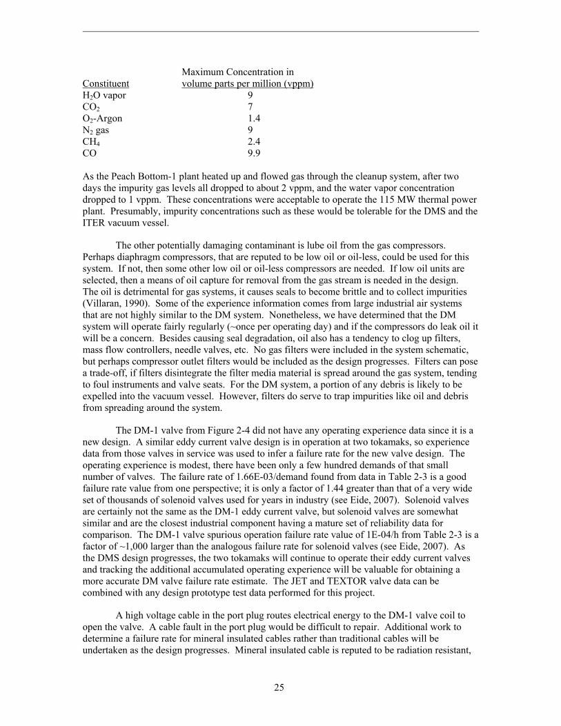
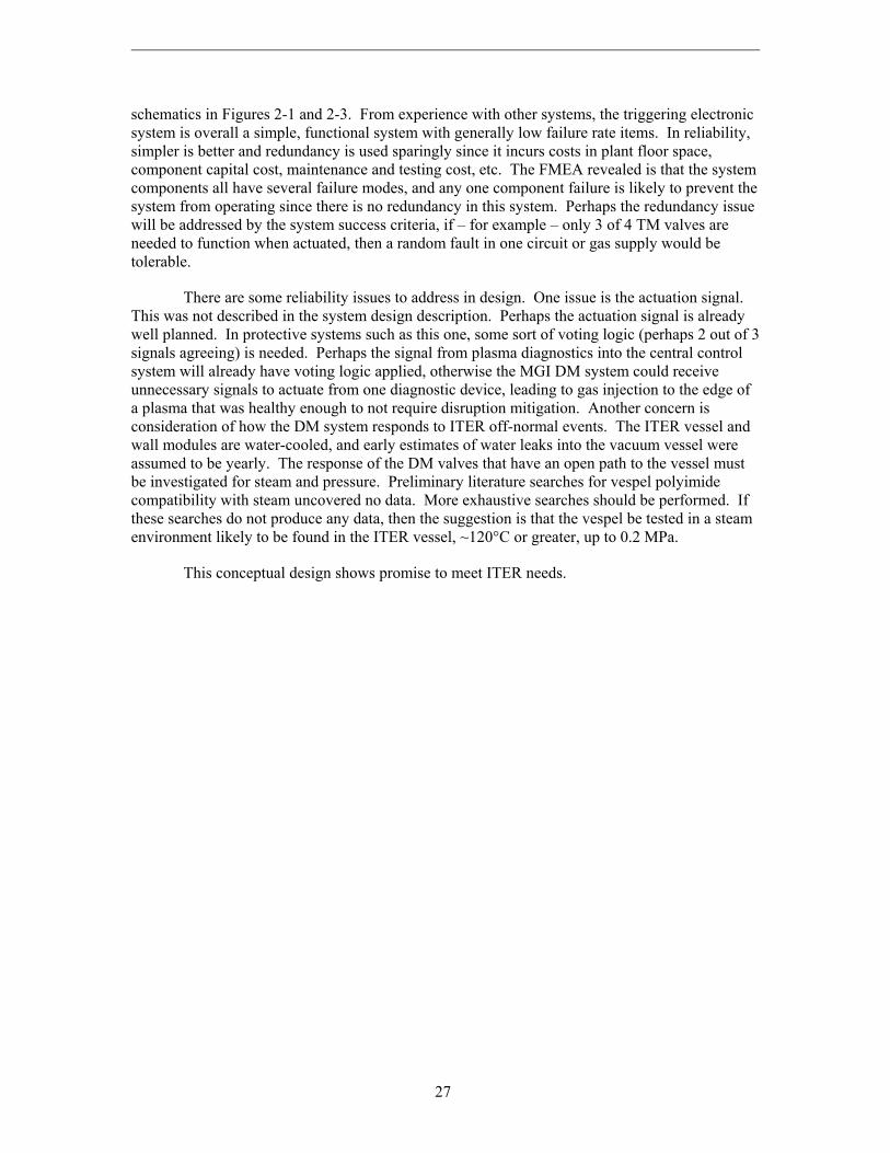
There are several issues to discuss in the conclusions and recommendations. Starting with the major risks, there is the possibility of chemical contamination in the gas used in this system. The cleanliness of the gas supplied by the ITER in-plant gas supply system is not known at this time. INL experience is that even research grade gases supplied in cylinders have ppm levels of impurities such as water vapor, air, and organic molecules. The impurity levels are low but can interfere with experiments. In reviewing past operating experiences in the nuclear industry, the Peach Bottom 1 high temperature helium-gas cooled fission reactor had the following impurity levels in its coolant helium during a plant startup following a maintenance outage (Scheffel, 1976):
25
Maximum Concentration in Constituent volume parts per million (vppm) H2O vapor 9 CO2 7 O2-Argon 1.4 N2 gas 9 CH4 2.4 CO 9.9 As the Peach Bottom-1 plant heated up and flowed gas through the cleanup system, after two days the impurity gas levels all dropped to about 2 vppm, and the water vapor concentration dropped to 1 vppm. These concentrations were acceptable to operate the 115 MW thermal power plant. Presumably, impurity concentrations such as these would be tolerable for the DMS and the ITER vacuum vessel.
The other potentially damaging contaminant is lube oil from the gas compressors. Perhaps diaphragm compressors, that are reputed to be low oil or oil-less, could be used for this system. If not, then some other low oil or oil-less compressors are needed. If low oil units are selected, then a means of oil capture for removal from the gas stream is needed in the design. The oil is detrimental for gas systems, it causes seals to become brittle and to collect impurities (Villaran, 1990). Some of the experience information comes from large industrial air systems that are not highly similar to the DM system. Nonetheless, we have determined that the DM system will operate fairly regularly (~once per operating day) and if the compressors do leak oil it will be a concern. Besides causing seal degradation, oil also has a tendency to clog up filters, mass flow controllers, needle valves, etc. No gas filters were included in the system schematic, but perhaps compressor outlet filters would be included as the design progresses. Filters can pose a trade-off, if filters disintegrate the filter media material is spread around the gas system, tending to foul instruments and valve seats. For the DM system, a portion of any debris is likely to be expelled into the vacuum vessel. However, filters do serve to trap impurities like oil and debris from spreading around the system.
The DM-1 valve from Figure 2-4 did not have any operating experience data since it is a new design. A similar eddy current valve design is in operation at two tokamaks, so experience data from those valves in service was used to infer a failure rate for the new valve design. The operating experience is modest, there have been only a few hundred demands of that small number of valves. The failure rate of 1.66E-03/demand found from data in Table 2-3 is a good failure rate value from one perspective; it is only a factor of 1.44 greater than that of a very wide set of thousands of solenoid valves used for years in industry (see Eide, 2007). Solenoid valves are certainly not the same as the DM-1 eddy current valve, but solenoid valves are somewhat similar and are the closest industrial component having a mature set of reliability data for comparison. The DM-1 valve spurious operation failure rate value of 1E-04/h from Table 2-3 is a factor of ~1,000 larger than the analogous failure rate for solenoid valves (see Eide, 2007). As the DMS design progresses, the two tokamaks will continue to operate their eddy current valves and tracking the additional accumulated operating experience will be valuable for obtaining a more accurate DM valve failure rate estimate. The JET and TEXTOR valve data can be combined with any design prototype test data performed for this project.
A high voltage cable in the port plug routes electrical energy to the DM-1 valve coil to open the valve. A cable fault in the port plug would be difficult to repair. Additional work to determine a failure rate for mineral insulated cables rather than traditional cables will be undertaken as the design progresses. Mineral insulated cable is reputed to be radiation resistant,

26
for example Saeki (2001) discussed that the conventional polymer insulation for a vacuum gauge cable embrittled and failed at 55 Mrads radiation exposure in service on a particle accelerator, while a Co-60 test of a mineral insulated cable (the leading candidate option to replace the failed cable) showed no cable insulation degradation at 190 Mrads exposure.
A potential safety issue was noted in the FMEA. Use of deuterium gas in this system poses explosion safety concerns. It was noted that if the D2 gas compressor drew in room air through an inlet leak then it might be possible to have a gas combustion event inside the compressor or piping. Perhaps the deuterium pressure would be too high within the compressor to allow air to be drawn in; and there is a design provision that would also preclude air ingress. The FMEA also noted that deuterium gas leaks into the port cell could potentially accumulate to achieve the minimum explosive concentration of 4.9% deuterium in air. The designers recognized this safety issue and are considering use of a positive pressure nitrogen atmosphere (purged) cask or enclosure to house the D2 compressor and associated equipment, and double-walled lines with a nitrogen purge in the annulus for the lines that must run outside the enclosure in the port cell (Lyttle, 2013). The preliminary safety report for ITER discusses that the equatorial port cells and upper port cells have no anti-deflagration zone assigned to them because all hydrogen-bearing components that have a vulnerability to leakage of the pipe work are to be doubly confined (RPrS, 2011). Therefore, the designer’s double confinement design idea meets the ITER double confinement safety requirements. The FMEA also queried if the port cell would have a hydrogen monitor. The port cell atmospheres are monitored for gamma radiation, tritium beta radiation, radioactive gases, and the atmospheres are sampled for radioactive dust and beryllium dust (RPrS, 2011). However, the port cell room atmospheres are not monitored for hydrogen species due to the double confinement of the protium, deuterium, and tritium isotopes. Double confinement uses guard pipes around process pipes and gloveboxes around valves. The steel gloveboxes maintain a nitrogen atmosphere, use safety glass windows, have glove ports protected by metal covers. The gloveboxes also use oxygen monitors to detect room air leakage into the glovebox and hydrogen monitors to detect any process gas leakage from the valves or pipes into the glovebox. The hydrogen specie gas lines are all-welded stainless steel (no flanged or screwed connections), and are surrounded by a guard pipe. The guard pipe annulus is operated at below atmospheric pressure. The guard pipe annulus is pumped down by the rough vacuum system (RPrS, 2011). It should be noted that when using additional safety barriers such as guard pipes and equipment enclosures, the maintenance time increases due to barrier entry (e.g., removing hatches or panels for ingress and establishing a safe atmosphere gas to allow maintenance work to proceed), then there is the additional time to reseal and test barrier integrity and re-establish a nitrogen atmosphere. The barriers themselves can require maintenance (replacing seals, painting, decontamination, etc.), and finally there is periodic inspection time for the barrier as well. These safety design provisions can be addressed in the future.
The scope of work was to perform a design support FMEA on this conceptual system. No reliability block diagram or fault tree was constructed of the system. Quantitatively, the reliability of the TM system to fire once on demand is estimated by the sum of the demand failure rates for 1 demand. An assumption is made that the system is fully and adequately prepared and is waiting for an actuation signal. Details of the trigger circuit power supply operating on demand are not known at this time, so the components that must function on demand are the set of DM-1 valves and the set of thyristors. R = 1 – [(4 thyristors)(3.125E-04/unit-demand)(1 d) + (4 valves)(1.66E-03/unit-demand)(1 d)] or R = 1 - 0.00789. Then R = 0.99211. The “one demand” reliability for the system is 99.2%.
Despite this 99% reliability for actuating the system, it is noted that this system is a single-path, series-component system; that is, there are no redundant components shown in the
27
schematics in Figures 2-1 and 2-3. From experience with other systems, the triggering electronic system is overall a simple, functional system with generally low failure rate items. In reliability, simpler is better and redundancy is used sparingly since it incurs costs in plant floor space, component capital cost, maintenance and testing cost, etc. The FMEA revealed is that the system components all have several failure modes, and any one component failure is likely to prevent the system from operating since there is no redundancy in this system. Perhaps the redundancy issue will be addressed by the system success criteria, if – for example – only 3 of 4 TM valves are needed to function when actuated, then a random fault in one circuit or gas supply would be tolerable.
There are some reliability issues to address in design. One issue is the actuation signal. This was not described in the system design description. Perhaps the actuation signal is already well planned. In protective systems such as this one, some sort of voting logic (perhaps 2 out of 3 signals agreeing) is needed. Perhaps the signal from plasma diagnostics into the central control system will already have voting logic applied, otherwise the MGI DM system could receive unnecessary signals to actuate from one diagnostic device, leading to gas injection to the edge of a plasma that was healthy enough to not require disruption mitigation. Another concern is consideration of how the DM system responds to ITER off-normal events. The ITER vessel and wall modules are water-cooled, and early estimates of water leaks into the vacuum vessel were assumed to be yearly. The response of the DM valves that have an open path to the vessel must be investigated for steam and pressure. Preliminary literature searches for vespel polyimide compatibility with steam uncovered no data. More exhaustive searches should be performed. If these searches do not produce any data, then the suggestion is that the vespel be tested in a steam environment likely to be found in the ITER vessel, ~120°C or greater, up to 0.2 MPa.
This conceptual design shows promise to meet ITER needs.
28
3.3 References
Eide, 2007. S. A. Eide et al., Industry-Average Performance for Components and Initiating Events at U.S. Commercial Nuclear Power Plants, NUREG/CR-6928, US Nuclear Regulatory Commission, February 2007, appendix A.
Lyttle, 2013. M. S. Lyttle, ITER designer at Oak Ridge National Laboratory, e-mail
communication on deuterium safety design, October 1, 2013. RPrS, 2011. Rapport Préliminaire de Sûreté, ITER IDM 3ZR2NC, version 3, December 12,
2011. Sections: vol I, Ch 9.3, p.10/41; vol I, Ch. 6.4.5, p.17/22; Vol II, Ch. 3.1, p.22/140 and Vol II, Ch. 3.1, p.91/140.
Saeki, 2001. H. Saeki, T. Aoki, T. Momose, “Mineral insulated gauge cable irradiated in the
Spring-8 storage ring,” Journal of Vacuum Science and Technology A, 19 (2001) 1022-1023.
Scheffel, 1976. W. J. Scheffel et al., Operating History Report for the Peach Bottom HTGR,
Volume 1, reactor operating history, GA-A13907, General Atomic Company, August 31, 1976.
Villaran, 1990. M. Villaran, R. Fullwood, M. Subudhi, Aging Assessment of Instrument Air
Systems in Nuclear Power Plants, NUREG/CR-5419, US Nuclear Regulatory Commission, January 1990.

29
Appendix A
Preliminary Failure Modes and Effects Analysis for the MGI DM System

30
Component Operational
State Failure Mode Possible Causes Preventive Action on Possible Causes Consequences
Corrective or Preventive Actions on
Consequences Comments Failure
rate
Comment on failure
rate
Criticality Number S•O=C Design comments
Argon and Neon compressor, Comp-1
Normally shutdown during DM system operation
Fails to start Electronics fault in control circuitry, software error, loss of power, human error, mechanical fault
Regular test, regular inspection, software QA, diverse power supplies, detailed operating procedures
Cannot charge the MGI DM valves with appropriate gas mixture, so no investment protection for the vacuum vessel. ITER outage until repaired.
Repair compressor to regain system operability and ITER operability
Hale (2001) gives some repair times. Compressor MTTR < 10 h. Thus, S=2
6.25E-03/d
and 200 d/y O=5
Blanchard 1998, Table 2-4 k factor of 1.25.
2x5=10
Fails to run Electronics fault in control circuitry, software error, loss of power, human error, mechanical fault
Regular test, regular inspection, software QA, diverse power supplies, detailed operating procedures
Cannot charge the MGI DM valves with appropriate gas mixture, so no investment protection for the vacuum vessel. ITER outage until repaired.
Repair compressor to regain system operability and ITER operability
Hale (2001) gives some repair times. Compressors < 10 h for MTTR. Thus, S=2
6.25E-05/h
and 200 d/y and 3 h/d O=3
Blanchard 1998, Table 2-4 k factor of 1.25.
2x3=6
Overspeed Electronics fault in control circuitry, software error
Regular test, and software QA
Overpressurize the gases, the system should compensate back to correct pressure
No immediate repair needed, but should investigate at first opportunity
Hale (2001) gives some repair times. Compressors < 10 h for MTTR. Thus, S=2
1.25E-05/h
and 200 d/y and 3 h/d O=3
Blanchard 1998, Table 2-4 k factor of 1.25.
2x3=6
Underspeed Electronics fault in control circuitry, software error
Regular test, and software QA
Underpressurizes the gases Repair compressor to regain system operability and ITER operability
Hale (2001) gives some repair times. Compressors < 10 h for MTTR. Thus, S=2
1.25E-05/h
and 200 d/y and 3 h/d O=3
Assumed from Blanchard 1998, Table 2-4 k factor of 1.25.
2x3=6
Fails to stop Electronics fault in control circuitry, software error
Regular test, and software QA
Overpressurize the gases, the system should compensate back to correct pressure
Operator can depower compressor from a motor control center or panel
Hale (2001) gives some repair times. Compressors < 10 h for MTTR. Thus, S=2
5E-03/d and 200 d/y O=5
Blanchard 1998, Table 2-4 k factor of 1.25.
2x5=10
Leakage at outlet side
Shaft seal fault, small crack
Regular test and inspection
Lose system pressure. Cannot reach specified gas pressure for DM valve
Hale (2001) gives some repair times. Compressors < 10 h for MTTR. Thus, S=2
3E-07/h 200 d/y and 3 h/d O=1
Blanchard 1998, no k factor needed
2x1=2
Leakage at inlet side
Shaft seal fault, small crack
Regular test and inspection
Compressor could draw room air into gas stream or leak gas, depending on the gas inlet pressure.
Contaminated gas Air contamination will decrease system effectiveness. Hale (2001) gives some repair times. Compressors < 10 h for MTTR. Thus, S=2
3E-07/h 200 d/y and 3 h/d O=1
Blanchard 1998, no k factor needed
2x1=2 Not easy to detect that air is drawn in to the compressor, probably by gas sampling.
Rupture of compressor body
Shaft seal failure, catastrophic crack
Regular test and inspection
Lose outlet gas pressure. Repair or replace compressor to regain system operability and ITER operability
Rupture assumed to require replacement. Assume < 1 week. Thus S=3
1E-08/h 200 d/y and 3 h/d O=1
Blanchard 1998, no k factor needed
3x1=3 Expected design IAW ASME B31.3, sect 301.2.2 - pressure relief device after compressor.
Contam-ination
Lube oil leaks by seals into gas
Compressor selection to preclude lube oil intrusion issue
Gas is contaminated with oil, oil enters vacuum vessel, degrades vacuum.
Select oil-less compressor, or use filters on compressor outlet
Oil often contaminates the gas in the compressor. Oil molecules become irradiated close to the tokamak, oil plugs filters, embrittles seals, fouls valves. Difficult repair, assume S=4
1/h O=6
Analyst judgment, no k factor needed
4x6=24 Assume a low oil or oil-less type of compressor is selected, perhaps a diaphragm compressor. Filters were not specified on the compressor inlet or outlet. Filters are recommended (Walker, 2011, p. 96-97), but filters can become plugged. Not easy to detect oil in process gas, periodic sampling should be done.

31
Component Operational
State Failure Mode Possible Causes Preventive Action on Possible Causes Consequences
Corrective or Preventive Actions on
Consequences Comments Failure
rate
Comment on failure
rate
Criticality Number S•O=C Design comments
Pressure regulator for argon and neon, Reg-1
Normally operating
Fail to regulate pressure to DM valve closure volume
Wear or fouling of poppet or seal in regulator allows pressure increase
Regular test and inspection, regular maintenance
Gas pressure high out of specifications delivered to the DM valve closure volume. Valve does not perform up to spec.
Pressure monitoring will alert operators to system being out of specification
Reported value is for all failure modes. Assume repair is < 8 h, so S=2
9.6E-08/h 200 d/y, 3 h/d O=1
Hale 2001, no k factor assumed
2x1=2 Air Liquide (2010) states diaphragm in regulator dries out when using very dry gas, so check monthly, replace more often than each 10 years.
Fails closed Spring relaxation or fracture, diaphragm failure
Regular test and inspection, regular maintenance
No gas delivered through regulator
Repair regulator to regain system operability and ITER operability
Assumed that a spring failure rate covers this failure mode. Assume repair is < 8 h, so S=2
1E-06/h 200 d/y, 3 h/d O=2
Dexter 1982, no k factor assumed
2x2=4
Leak across diaphragm
Gas diffusion Specify diaphragm for low loss
Gas leaks out of regulator Monitor Ar, Ne in port cell, routine ventilation of port cell
Reported value is for all failure modes. Assume repair is < 8 h, so S=2
9.6E-08/h 3000 h/y O=1
Hale 2001, no k factor assumed
2x1=2 Gas leak into port cell may not be easy to detect. Oxygen monitor?
Gas valve near regulator, Valve-1 (assume motor operated valve)
Normally open
Spurious operation
Command fault, human error, electronic noise
Periodic testing, software QA
Valve closes, isolates gas supply. Cannot recharge that DM valve closure volume. ITER outage to repair.
Repair valve to regain system operability
Perhaps there are success criteria on how many DM valves can be failed and still allow ITER to operate. Hale 2001, MTTR=8 h, so S=2
6.18E-07/h
3000 h/y O=2
Blanchard 1998, Table 2-4 k factor of 2.06
2x2=4 Must better define success criteria of the MGI DM system, perhaps one of 4 TM valves can be down.
Plugging Moisture in system creates rust that fouls valve, foreign material in system such as hydro-carbons gum up valve disk and seat
Regular sampling of gas in system for impurities and foreign materials, monitor moisture in system
Cannot charge the MGI DM valve closure volume with appropriate gas pressure, so no machine protection for the vacuum vessel. ITER outage until repaired.
Repair valve to regain system operability.
Cleaning gas piping is a difficult repair, assume S=3
5E-07/h and 3000 h/y O=2
Blanchard 1998, no k factor assigned
3x2=6 The DM valve could be damaged by operation with no gas cushion in the closure volume. The cleaning task would be to flush piping with cleaning agent, keeping moisture out of piping.
Internal leak past seat
Seat wear, not fully seated by valve operator
Regular sampling of gas in system for foreign materials, check motor current
Minor problem for small leak. Can operate the system.
Repair valve next outage.
Hale 2001, MTTR=8 h, so S=2 1E-05/h 3000 h/y O=4
Blanchard 1998, no k factor assigned
2x4=8 Leak past the seat is difficult to detect.
Internal rupture
Valve disk failure, seat mechanical failure
High QA on valve Loss of control of gas flow. Valve-2 can provide system operation.
Repair valve next outage.
Replacing a valve disk and returning the system to service, judgment is S=2
5E-07/h 3000 h/y O=2
Blanchard 1998, no k factor assigned
2x2=4
External leak Stem seal degradation, valve body crack
High QA on valve, periodic inspection of stem seal
Wasting gas from the ITER gas supply. System can operate with a small leak.
Repair valve next outage.
Replacing a valve and returning the system to service, judgment is S=3
1E-07/h 3000 h/y O=2
Blanchard 1998, no k factor assigned
3x2=6 Gas leak into port cell may not be easy to detect.
External rupture
Stem seal failure, valve body failure
High QA on valve, periodic inspection of stem seal
Cannot charge DM valve closure volume, ITER outage until repaired.
Repair valve to regain system operability.
Replacing a valve and returning the system to service, judgment is S=3
5E-09/h 3000 h/y O=1
Blanchard 1998, no k factor assigned
3x1=3 Not clear if DM valve would be damaged by no pressure in the closure volume.
Pressure sensor in Argon-Neon line, PS-1
Normally operating
Fails to operate
Open circuit, short circuit
High QA on sensor, periodic test
Cannot charge DM valve closure volume to spec, DM valve will not operate correctly, but will open.
Repair sensor next outage.
Hale 2001, Pressure control MTTR=5.6 h, S=2
1.25E-06/h
3000 h/y O=2
Cadwallader 1996, Table 2-4 k factor of 1.25.
2x2=4 Failed pressure sensor will be obvious. Many designers have noted they would have put redundant sensors into design. Or, resilient sensors (Beck, 2011).
Erratic reading
EM interference, foreign material buildup in unit
Shield for EM energy, specify clean gas in system
Cannot charge DM valve closure volume to spec, valve will not operate correctly, but will open.
Repair sensor next outage.
Assume 50% of the failure to operate failure rate, so 5E-07/h, Table 2-4 k factor of 1.25 gives 6.25E-07/h. From Hale 2001, Pressure control MTTR=5.6 h, S=2
6.25E-07/h
3000 h/y O=2
Analyst judgment
2x2=4

32
Component Operational
State Failure Mode Possible Causes Preventive Action on Possible Causes Consequences
Corrective or Preventive Actions on
Consequences Comments Failure
rate
Comment on failure
rate
Criticality Number S•O=C Design comments
PS-1, continued Normally operating
External leak Fitting fault or crack, sensing line fault
High QA on parts, installation. Periodic inspection
Small leak is wasting gas from the ITER gas supply.
Repair sensor next outage.
Assume 1-m sensing line. Hale 2001, Pressure control MTTR=5.6 h, S=2
1E-07/h 3000 h/y O=2
Blanchard 1998, no k factor
2x2=4 Gas leak into port cell may not be easy to detect.
External rupture
Fitting failure, sensing line break
High QA on parts, installation. Periodic inspection
PS-1 is failed, system is leaking gas to port cell. ITER outage until repaired.
Isolate gas from the break. Repair sensor as soon as possible.
Assume 1-m sensing line. Replace sensor, return system to service, assume S=2
3.3E-09/h 3000 h/y O=1
Blanchard 1998, no k factor
2x1=2
Gas valve near PS-1, Valve-2 (assume motor operated valve)
Normally closed
Spurious operation
Command fault, human error, electronic noise
Periodic testing, software QA
Valve opens, unisolates PS-1 sensor. Leaves sensor exposed to pressure pulse of DM valve operation.
Can operate system with this failure. Repair valve to regain system integrity.
Hale 2001, MTTR=8 h, so S=2 6.18E-07/h
3000 h/y O=2
Blanchard 1998, Table 2-4 k factor of 2.06
2x2=4 DM valve operation could damage PS-1 by pressure pulsations from the closure volume.
Plugging Moisture in system may create rust that fouls valve, foreign material in system such as hydrocarbons gum up valve disk and seat
Regular sampling of gas in system for impurities and foreign materials, monitor moisture in system
Cannot charge the MGI DM valve closure volume with appropriate gas pressure, so DM valve is not optimum but can function. Longer than 3 hours to restore DM valve.
Can operate system with this failure. Repair valve to regain system integrity.
Cleaning gas piping is a difficult repair, assume S=3
5E-07/h and 3000 h/y O=2
Blanchard 1998, no k factor assigned
3x2=6 The cleaning task would be to flush piping with cleaning agent, keeping moisture out of piping.
Internal leak past seat
Seat wear, not fully seated by valve operator
Regular sampling of gas in system for foreign materials, check motor current
Minor degradation of system.
Repair valve next outage.
Hale 2001, MTTR=8 h, so S=2 1E-05/h 3000 h/y O=4
Blanchard 1998, no k factor assigned
2x4=8 Leak past the seat is difficult to detect.
Internal rupture
Valve disk failure, seat mechanical failure
High QA on valve Cannot isolate PS-1 from pressure pulse of DM valve operation, could fail sensor
Repair valve to regain system operability.
judgment is S=2 5E-07/h 3000 h/y O=2
Blanchard 1998, no k factor assigned
2x2=4
External leak Stem seal degradation, valve body crack
High QA on valve, periodic inspection of stem seal
Wasting gas from the ITER gas supply. System can operate with a small leak.
Repair valve next outage.
Replacing a valve and returning the system to service, judgment is S=3
1E-07/h 3000 h/y O=2
Blanchard 1998, no k factor assigned
3x2=6 Gas leak into port cell may not be easy to detect.
External rupture
Stem seal failure, valve body failure
High QA on valve, periodic inspection of stem seal
Cannot charge DM valve closure volume, ITER outage until repaired.
Repair valve to regain system operability.
Replacing a valve and returning the system to service, judgment is S=3
5E-09/h 3000 h/y O=1
Blanchard 1998, no k factor assigned
3x1=3
Deuterium compressor, Comp-2
Shutdown during system operation
Fails to start Electronics fault in control circuitry, software error, loss of power, human error, mechanical fault
Regular test, regular inspection, software QA, diverse power supplies, detailed operating procedures
Cannot charge the MGI DM valves with deuterium, but can run DM valves with Ar-Ne mix so DM system can still protect vacuum vessel.
Repair compressor to regain system operability
Hale (2001) gives some repair times. Compressors < 10 h for MTTR. Thus, S=2
6.25E-03/d
and 200 d/y O=5
Blanchard 1998, Table 2-4 k factor of 1.25.
2x5=10
Fails to run Electronics fault in control circuitry, software error, loss of power, human error, mechanical fault
Regular test, regular inspection, software QA, diverse power supplies, detailed operating procedures
Cannot charge the MGI DM valves with deuterium, but can run DM valves with Ar-Ne mix so can protect vacuum vessel.
Repair compressor to regain system operability
Hale (2001) gives some repair times. Compressors < 10 h for MTTR. Thus, S=2
6.25E-05/h
and 200 d/y and 3 h/d O=3
Blanchard 1998, Table 2-4 k factor of 1.25.
2x3=6
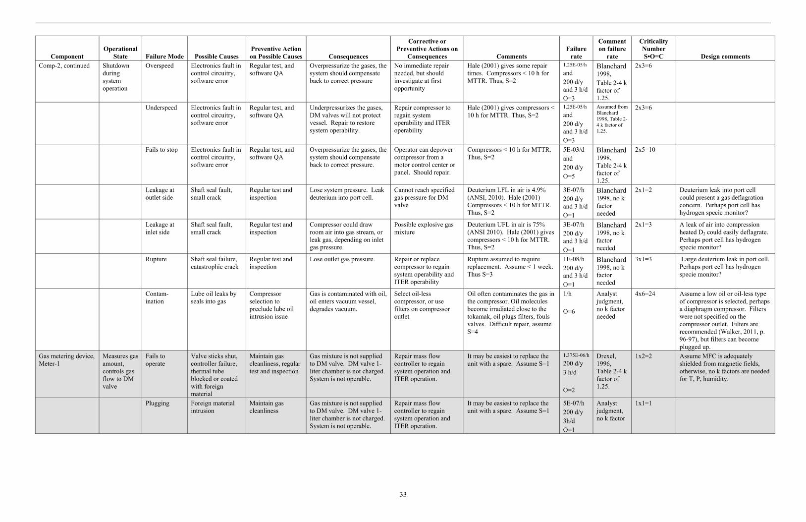
33
Component Operational
State Failure Mode Possible Causes Preventive Action on Possible Causes Consequences
Corrective or Preventive Actions on
Consequences Comments Failure
rate
Comment on failure
rate
Criticality Number S•O=C Design comments
Comp-2, continued Shutdown during system operation
Overspeed Electronics fault in control circuitry, software error
Regular test, and software QA
Overpressurize the gases, the system should compensate back to correct pressure
No immediate repair needed, but should investigate at first opportunity
Hale (2001) gives some repair times. Compressors < 10 h for MTTR. Thus, S=2
1.25E-05/h
and 200 d/y and 3 h/d O=3
Blanchard 1998, Table 2-4 k factor of 1.25.
2x3=6
Underspeed Electronics fault in control circuitry, software error
Regular test, and software QA
Underpressurizes the gases, DM valves will not protect vessel. Repair to restore system operability.
Repair compressor to regain system operability and ITER operability
Hale (2001) gives compressors < 10 h for MTTR. Thus, S=2
1.25E-05/h
and 200 d/y and 3 h/d O=3
Assumed from Blanchard 1998, Table 2-4 k factor of 1.25.
2x3=6
Fails to stop Electronics fault in control circuitry, software error
Regular test, and software QA
Overpressurize the gases, the system should compensate back to correct pressure.
Operator can depower compressor from a motor control center or panel. Should repair.
Compressors < 10 h for MTTR. Thus, S=2
5E-03/d and 200 d/y O=5
Blanchard 1998, Table 2-4 k factor of 1.25.
2x5=10
Leakage at outlet side
Shaft seal fault, small crack
Regular test and inspection
Lose system pressure. Leak deuterium into port cell.
Cannot reach specified gas pressure for DM valve
Deuterium LFL in air is 4.9% (ANSI, 2010). Hale (2001) Compressors < 10 h for MTTR. Thus, S=2
3E-07/h 200 d/y and 3 h/d O=1
Blanchard 1998, no k factor needed
2x1=2 Deuterium leak into port cell could present a gas deflagration concern. Perhaps port cell has hydrogen specie monitor?
Leakage at inlet side
Shaft seal fault, small crack
Regular test and inspection
Compressor could draw room air into gas stream, or leak gas, depending on inlet gas pressure.
Possible explosive gas mixture
Deuterium UFL in air is 75% (ANSI 2010). Hale (2001) gives compressors < 10 h for MTTR. Thus, S=2
3E-07/h 200 d/y and 3 h/d O=1
Blanchard 1998, no k factor needed
2x1=3 A leak of air into compression heated D2 could easily deflagrate. Perhaps port cell has hydrogen specie monitor?
Rupture Shaft seal failure, catastrophic crack
Regular test and inspection
Lose outlet gas pressure. Repair or replace compressor to regain system operability and ITER operability
Rupture assumed to require replacement. Assume < 1 week. Thus S=3
1E-08/h 200 d/y and 3 h/d O=1
Blanchard 1998, no k factor needed
3x1=3 Large deuterium leak in port cell. Perhaps port cell has hydrogen specie monitor?
Contam-ination
Lube oil leaks by seals into gas
Compressor selection to preclude lube oil intrusion issue
Gas is contaminated with oil, oil enters vacuum vessel, degrades vacuum.
Select oil-less compressor, or use filters on compressor outlet
Oil often contaminates the gas in the compressor. Oil molecules become irradiated close to the tokamak, oil plugs filters, fouls valves. Difficult repair, assume S=4
1/h O=6
Analyst judgment, no k factor needed
4x6=24 Assume a low oil or oil-less type of compressor is selected, perhaps a diaphragm compressor. Filters were not specified on the compressor outlet. Filters are recommended (Walker, 2011, p. 96-97), but filters can become plugged up.
Gas metering device, Meter-1
Measures gas amount, controls gas flow to DM valve
Fails to operate
Valve sticks shut, controller failure, thermal tube blocked or coated with foreign material
Maintain gas cleanliness, regular test and inspection
Gas mixture is not supplied to DM valve. DM valve 1-liter chamber is not charged. System is not operable.
Repair mass flow controller to regain system operation and ITER operation.
It may be easiest to replace the unit with a spare. Assume S=1
1.375E-06/h
200 d/y 3 h/d O=2
Drexel, 1996, Table 2-4 k factor of 1.25.
1x2=2 Assume MFC is adequately shielded from magnetic fields, otherwise, no k factors are needed for T, P, humidity.
Plugging Foreign material intrusion
Maintain gas cleanliness
Gas mixture is not supplied to DM valve. DM valve 1-liter chamber is not charged. System is not operable.
Repair mass flow controller to regain system operation and ITER operation.
It may be easiest to replace the unit with a spare. Assume S=1
5E-07/h 200 d/y 3h/d O=1
Analyst judgment, no k factor
1x1=1

34
Component Operational
State Failure Mode Possible Causes Preventive Action on Possible Causes Consequences
Corrective or Preventive Actions on
Consequences Comments Failure
rate
Comment on failure
rate
Criticality Number S•O=C Design comments
Meter-1, continued Measures gas amount, controls gas flow to DM valve
Drift Valve sticking, potentiometer drift, gas temperature variation, RF heating in wires of thermal tube
Maintain gas cleanliness, maintain temperature in room, regular test and inspection, magnetic shielding
Correct gas mixture may not be supplied to DM valve. DM valve may still function with improper gas mixture.
Routine check of MFC may reveal problem.
It may be easiest to replace the unit with a spare. Assume S=1
1.375E-06/h
200 d/y 3 h/d O=2
Drexel, 1996, Table 2-4 k factor of 1.25.
1x2=2
Erratic operation
Power fluctuations, gas temperature fluctuations, moisture in gas, RF heating in wires of thermal tube
Maintain gas cleanliness, maintain temperature in room, regular test and inspection, magnetic shielding
DM valve not supplied with proper gas mixture. Valve may not reach 40 bar pressure or proper mixture of Ar, Ne, D2
Repair mass flow controller to regain system operation and ITER operation.
It may be easiest to replace the unit with a spare. Assume S=1
1.375E-06/h
200 d/y 3 h/d O=2
Drexel, 1996, Table 2-4 k factor of 1.25.
1x2=2
External leak Crack, fitting leak Vibration, construction fault, corrosion
Ar, Ne, D2 gas mixture leaks to port cell. Extra time to deliver gas mixture to DM valve.
Repair mass flow controller to regain system operation and ITER operation.
It may be easiest to replace the unit with a spare. Assume S=1
1E-07/h 200 d/y 3 h/d O=1
Analyst judgment, no k factor
1x1=1
External rupture
Large crack, fitting failure
Material flaw, corrosion
Lose gas to the port cell. System is not operable.
Repair mass flow controller to regain system operation and ITER operation.
It may be easiest to replace the unit with a spare. Assume S=1
5E-09/h 200d/y 3h/d O=1
Analyst judgment, no k factor
1x1=1
Gas Piping in port plug, Piping-1
Normally operating
External leak Weld fault, pipe wall flaw, construction fault
Materials selection in design, pre-service inspection, low vibration in design, NDT
Ar, Ne, D2 gas mixture leaks to port plug. Extra gas in port plug will raise pressure, become irradiated. Extra time needed to deliver gas mixture to DM valve.
Port plug should not become pressurized. Repair pipe leak to regain system integrity.
Assumed 6 m of piping in port plug. Failure Severity is high, repairs in port plug are difficult. Assume S=5
1E-07/h 200 d/y 3 h/d O=1
Failure rate described in section 2.4
5x1=5 Assuming stainless steel piping is low magnetic permeability so that there is low magnetic force, low heating, low eddy current (perhaps no need for a ceramic break in the line?)
External rupture
Weld failure, wall cracking, wall thinning, construction fault
Materials selection in design, pre-service inspection, low vibration in design, NDT
Lose gas to the port plug. System is not operable.
Port plug should not become pressurized. Repair pipe leak to regain system integrity.
Assumed 6 m of piping in port plug. Failure Severity is high, repairs in port plug are difficult. Assume S=5. Analyst judgment, rupture is 0.1 of leakage value.
1E-08/h 200 d/y 3 h/d O=1
Analyst judgment, environment factors accounted for
5x1=5
plugging impurity buildup, corrosion product buildup from moisture in gas, foreign material or debris buildup
Good gas purity No gas delivered to DM valve. System is not operable.
Clear out pipe to regain system integrity.
Assumed 6 m of piping in port plug. Failure Severity is high, repairs in port plug are difficult. Assume S=5. Assume plugging is 0.1 of leakage value.
1E-08/h 200 d/y 3 h/d O=1
Analyst judgment, no k factor
5x1=5
Vacuum piping in port plug, Vpiping-1
Normally operating, but valved out in port cell
External leak Weld fault, pipe wall flaw, construction fault
Materials selection in design, pre-service inspection, low vibration in design, NDT
Drawing port plug rarefied air into system? Port plug vacuum may draw air from vacuum line, depends on vacuum pressures. Leaks gas mixture to port plug when actuated.
Repair pipe to regain system proper operation.
Assumed 6 m of piping in port plug. Failure Severity is high, repairs in port plug are difficult. Assume S=5
1E-07/h 200 d/y 3 h/d O=1
Failure rate described in section 2.4
5x1=5 Vacuum piping tends to be thin walled, but for this initial analysis a typical pipe failure rate was used.
External rupture
Weld failure, wall cracking, construction fault
Materials selection in design, pre-service inspection, low vibration in design, NDT
Vacuum line is failed, cannot evacuate DM valve with this line. Can actuate the valve to ‘safe’ the system.
Repair pipe to regain system proper operation.
Assumed 6 m of piping in port plug. Failure Severity is high, repairs in port plug are difficult. Assume S=5. Analyst judgment, rupture is 0.1 of leakage value.
1E-08/h 200 d/y 3 h/d O=1
Analyst judgment, environment factors accounted for
5x1=5

35
Component Operational
State Failure Mode Possible Causes Preventive Action on Possible Causes Consequences
Corrective or Preventive Actions on
Consequences Comments Failure
rate
Comment on failure
rate
Criticality Number S•O=C Design comments
Vpiping-1, continued Normally operating, but valved out in port cell
plugging Foreign material or debris buildup creates poor conductance
Good gas purity, vespel seal integrity
Vacuum line is failed, cannot evacuate DM valve with this line. Can actuate the valve to ‘safe’ the system.
Clear out pipe to regain system proper operation.
Assumed 6 m of piping in port plug. Failure Severity is high, repairs in port plug are difficult. Assume S=5. Assume plugging is 0.1 of leakage value.
1E-08/h 200 d/y 3 h/d O=1
Analyst judgment
5x1=5
Gas Piping in port cell, Piping-2
Normally operating
External leak Weld fault, pipe wall flaw, construction fault
Materials selection in design, pre-service inspection, low vibration in design, NDT
Ar, Ne, D2 gas mixture leaks to port cell. Explosion concern? D2 LFL is 4.9% in air. Extra time needed to deliver gas mixture to DM valve.
Repair pipe leak to regain system integrity.
Assumed 30 m of piping in port cell. Failure Severity is moderate, pipe repairs should be less than a week. Assume S=3.
5.1E-07/h 200 d/y 3 h/d O=1
Failure rate described in section 2.4
3x1=3 Assuming stainless steel piping is low magnetic permeability so that there is low magnetic force, low heating, low eddy current (maybe no need for ceramic break in line)
External rupture
Weld failure, wall cracking, wall thinning, construction fault
Materials selection in design, pre-service inspection, low vibration in design, NDT
Lose gas to the port plug. System is not operable. Explosion concern? D2 LFL is 4.9% in air.
Repair pipe leak to regain system integrity.
Assumed 30 m of piping in port cell. Failure Severity is moderate, pipe repairs should be less than a week. Assume S=3. Analyst judgment, rupture is 0.1 of leakage value.
5.1E-08/h 200 d/y 3 h/d O=1
Analyst judgment, environment factors accounted for
3x1=3
plugging impurity buildup, corrosion product buildup from moisture in gas, foreign material or debris buildup
Good gas purity No gas delivered to DM valve. System is not operable.
Clear out pipe to regain system integrity.
Assumed 30 m of piping in port cell. Failure Severity is moderate, pipe repairs should be less than a week. Assume S=3. Analyst judgment, plugging is 0.1 of leakage value.
5.1E-08/h 200 d/y 3 h/d O=1
Analyst judgment, no k factor
3x1=3
Vacuum piping in port cell, Vpiping-2
Normally operating, but valved out in port cell
External leak Weld fault, pipe wall flaw, construction fault
Materials selection in design, pre-service inspection, low vibration in design, NDT
Drawing port cell air into system. When vacuum purge
Repair pipe to regain system proper operation.
Assumed 30 m of piping in port cell. Failure Severity is moderate, pipe repair should be less than a week. Assume S=3
1E-07/h 200 d/y 3 h/d O=1
Failure rate described in section 2.4
5x1=5 Vacuum piping tends to be thin walled, but for this initial analysis a typical pipe failure rate was used.
External rupture
Weld failure, wall cracking, construction fault
Materials selection in design, pre-service inspection, low vibration in design, NDT
Vacuum line is failed, cannot evacuate DM valve with this line. Can actuate the valve to ‘safe’ the system.
Repair pipe to regain system proper operation.
Assumed 6 m of piping in port plug. Failure Severity is moderate, pipe repair should be less than a week. Assume S=3. Analyst judgment, rupture is 0.1 of leakage value.
1E-08/h 200 d/y 3 h/d O=1
Analyst judgment, environment factors accounted for
5x1=5
Plugging Foreign material or debris buildup creates poor conductance
Good gas purity, vespel seal integrity
Vacuum line is failed, cannot evacuate DM valve with this line. Can actuate the valve to ‘safe’ the system.
Clear out pipe to regain system proper operation.
Assumed 6 m of piping in port plug. Failure Severity is moderate, pipe repair should be less than a week. Assume S=3. Assume plugging is 0.1 of leakage value.
1E-08/h 200 d/y 3 h/d O=1
Analyst judgment, no k factor
5x1=5
Meter outlet valve, Valve-3 (isolates Meter-1 when using vacuum line)
Normally closed
Spurious operation
Command fault, human error, electronic noise
Periodic testing, software QA, noise shielding
Valve opens, unisolates Meter-1.
Can operate system with this failure. Repair valve to regain system integrity.
Hale 2001, MTTR=8 h, so S=2 6.18E-07/h
3000 h/y O=2
Blanchard 1998, Table 2-4 k factor of 2.06
2x2=4
Plugging Moisture in system may create rust that fouls valve, foreign material in system such as hydrocarbons gum up valve disk and seat
Regular sampling of gas in system for impurities and foreign materials, monitor moisture in system
Cannot charge the MGI DM valve closure volume with appropriate gas pressure, so DM valve is not optimum but can function. Longer than 3 hours to restore DM valve.
Can operate system with this failure. Repair valve to regain system integrity.
Cleaning gas piping is a difficult repair, assume S=3
5E-07/h and 3000 h/y O=2
Blanchard 1998, no k factor assigned
3x2=6 The cleaning task would be to flush piping with cleaning agent, keeping moisture out of piping.
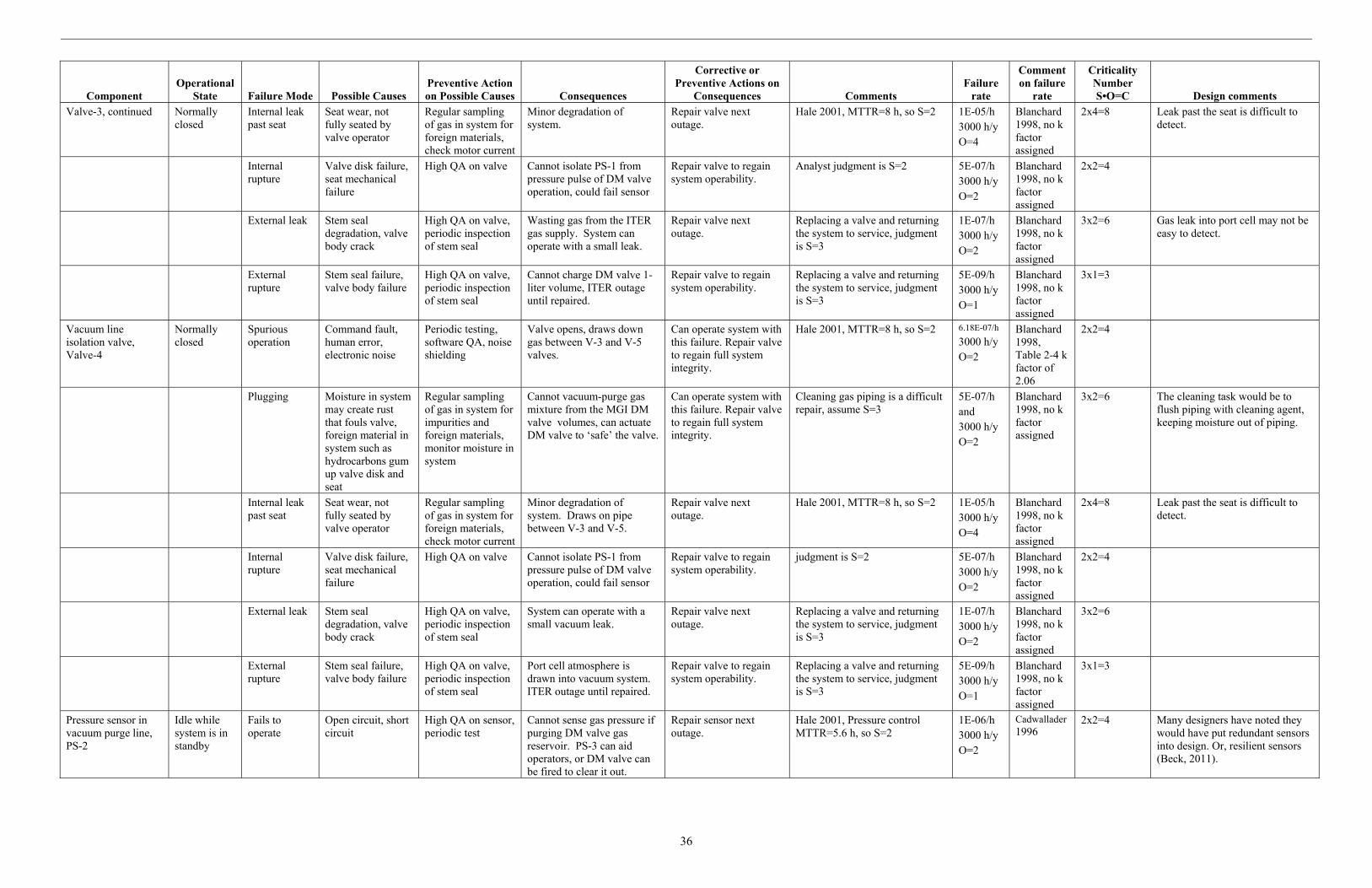
36
Component Operational
State Failure Mode Possible Causes Preventive Action on Possible Causes Consequences
Corrective or Preventive Actions on
Consequences Comments Failure
rate
Comment on failure
rate
Criticality Number S•O=C Design comments
Valve-3, continued Normally closed
Internal leak past seat
Seat wear, not fully seated by valve operator
Regular sampling of gas in system for foreign materials, check motor current
Minor degradation of system.
Repair valve next outage.
Hale 2001, MTTR=8 h, so S=2 1E-05/h 3000 h/y O=4
Blanchard 1998, no k factor assigned
2x4=8 Leak past the seat is difficult to detect.
Internal rupture
Valve disk failure, seat mechanical failure
High QA on valve Cannot isolate PS-1 from pressure pulse of DM valve operation, could fail sensor
Repair valve to regain system operability.
Analyst judgment is S=2 5E-07/h 3000 h/y O=2
Blanchard 1998, no k factor assigned
2x2=4
External leak Stem seal degradation, valve body crack
High QA on valve, periodic inspection of stem seal
Wasting gas from the ITER gas supply. System can operate with a small leak.
Repair valve next outage.
Replacing a valve and returning the system to service, judgment is S=3
1E-07/h 3000 h/y O=2
Blanchard 1998, no k factor assigned
3x2=6 Gas leak into port cell may not be easy to detect.
External rupture
Stem seal failure, valve body failure
High QA on valve, periodic inspection of stem seal
Cannot charge DM valve 1-liter volume, ITER outage until repaired.
Repair valve to regain system operability.
Replacing a valve and returning the system to service, judgment is S=3
5E-09/h 3000 h/y O=1
Blanchard 1998, no k factor assigned
3x1=3
Vacuum line isolation valve, Valve-4
Normally closed
Spurious operation
Command fault, human error, electronic noise
Periodic testing, software QA, noise shielding
Valve opens, draws down gas between V-3 and V-5 valves.
Can operate system with this failure. Repair valve to regain full system integrity.
Hale 2001, MTTR=8 h, so S=2 6.18E-07/h
3000 h/y O=2
Blanchard 1998, Table 2-4 k factor of 2.06
2x2=4
Plugging Moisture in system may create rust that fouls valve, foreign material in system such as hydrocarbons gum up valve disk and seat
Regular sampling of gas in system for impurities and foreign materials, monitor moisture in system
Cannot vacuum-purge gas mixture from the MGI DM valve volumes, can actuate DM valve to ‘safe’ the valve.
Can operate system with this failure. Repair valve to regain full system integrity.
Cleaning gas piping is a difficult repair, assume S=3
5E-07/h and 3000 h/y O=2
Blanchard 1998, no k factor assigned
3x2=6 The cleaning task would be to flush piping with cleaning agent, keeping moisture out of piping.
Internal leak past seat
Seat wear, not fully seated by valve operator
Regular sampling of gas in system for foreign materials, check motor current
Minor degradation of system. Draws on pipe between V-3 and V-5.
Repair valve next outage.
Hale 2001, MTTR=8 h, so S=2 1E-05/h 3000 h/y O=4
Blanchard 1998, no k factor assigned
2x4=8 Leak past the seat is difficult to detect.
Internal rupture
Valve disk failure, seat mechanical failure
High QA on valve Cannot isolate PS-1 from pressure pulse of DM valve operation, could fail sensor
Repair valve to regain system operability.
judgment is S=2 5E-07/h 3000 h/y O=2
Blanchard 1998, no k factor assigned
2x2=4
External leak Stem seal degradation, valve body crack
High QA on valve, periodic inspection of stem seal
System can operate with a small vacuum leak.
Repair valve next outage.
Replacing a valve and returning the system to service, judgment is S=3
1E-07/h 3000 h/y O=2
Blanchard 1998, no k factor assigned
3x2=6
External rupture
Stem seal failure, valve body failure
High QA on valve, periodic inspection of stem seal
Port cell atmosphere is drawn into vacuum system. ITER outage until repaired.
Repair valve to regain system operability.
Replacing a valve and returning the system to service, judgment is S=3
5E-09/h 3000 h/y O=1
Blanchard 1998, no k factor assigned
3x1=3
Pressure sensor in vacuum purge line, PS-2
Idle while system is in standby
Fails to operate
Open circuit, short circuit
High QA on sensor, periodic test
Cannot sense gas pressure if purging DM valve gas reservoir. PS-3 can aid operators, or DM valve can be fired to clear it out.
Repair sensor next outage.
Hale 2001, Pressure control MTTR=5.6 h, so S=2
1E-06/h 3000 h/y O=2
Cadwallader 1996
2x2=4 Many designers have noted they would have put redundant sensors into design. Or, resilient sensors (Beck, 2011).

37
Component Operational
State Failure Mode Possible Causes Preventive Action on Possible Causes Consequences
Corrective or Preventive Actions on
Consequences Comments Failure
rate
Comment on failure
rate
Criticality Number S•O=C Design comments
PS-2, continued Idle while system is in standby
Erratic reading
EM interference, foreign material buildup in unit
Shield for EM energy, specify clean gas
Cannot track DM valve gas sweep to vacuum line. PS-3 could support the valve purge to vacuum.
Repair sensor next outage.
Assume 50% of the failure to operate failure rate, so 5E-07/h Hale 2001, Pressure control MTTR=5.6 h, so S=2
5E-07/h 3000 h/y O=2
Analyst judgment
2x2=4
External leak Fitting fault or crack, sensing line fault
High QA on parts, installation. Periodic inspection
Small leak is drawing air into vacuum line, wasting ITER resources on gas handling.
Repair sensor next outage.
Assume 1-m sensing line, Hale 2001, Pressure control MTTR=5.6 h, so S=2
1E-07/h 3000 h/y O=2
Blanchard 1998
2x2=4 Gas leak into port cell may not be easy to detect.
External rupture
Fitting failure, sensing line break
High QA on parts, installation. Periodic inspection
PS-2 is failed, system is drawing air from port cell. Wasting ITER resources on gas handling until repaired.
Isolate vacuum line. Repair sensor as soon as possible.
Assume 1-m sensing line. Replace sensor, return system to service, assume S=2
3.3E-09/h 3000 h/y O=1
Blanchard 1998
2x1=2
Gas line isolation valve, Valve-5
Normally closed
Spurious operation
Command fault, human error, electronic noise
Periodic testing, software QA, noise shielding
Valve opens, unisolates Meter-1.
Can operate system with this failure. Repair valve to regain system integrity.
Hale 2001, MTTR=8 h, so S=2 6.18E-07/h
3000 h/y O=2
Blanchard 1998, Table 2-4 k factor of 2.06
2x2=4
Plugging Moisture in system may create rust that fouls valve, foreign material in system such as hydrocarbons gum up valve disk and seat
Regular sampling of gas in system for impurities and foreign materials, monitor moisture in system
Cannot charge the MGI DM valve closure volume with appropriate gas pressure, so DM valve is not optimum but can function. Longer than 3 hours to restore DM valve.
Can operate system with this failure. Repair valve to regain system integrity.
Cleaning gas piping is a difficult repair, assume S=3
5E-07/h and 3000 h/y O=2
Blanchard 1998, no k factor assigned
3x2=6 The cleaning task would be to flush piping with cleaning agent, keeping moisture out of piping.
Internal leak past seat
Seat wear, not fully seated by valve operator
Regular sampling of gas in system for foreign materials, check motor current
Minor degradation of system.
Repair valve next outage.
Hale 2001, MTTR=8 h, so S=2 1E-05/h 3000 h/y O=4
Blanchard 1998, no k factor assigned
2x4=8 Leak past the seat is difficult to detect.
Internal rupture
Valve disk failure, seat mechanical failure
High QA on valve Cannot isolate PS-1 from pressure pulse of DM valve operation, could fail sensor
Repair valve to regain system operability.
Analyst assumes S=2 5E-07/h 3000 h/y O=2
Blanchard 1998, no k factor assigned
2x2=4
External leak Stem seal degradation, valve body crack
High QA on valve, periodic inspection of stem seal
Wasting gas from the ITER gas supply. System can operate with a small leak.
Repair valve next outage.
Replacing a valve and returning the system to service, judgment is S=3
1E-07/h 3000 h/y O=2
Blanchard 1998, no k factor assigned
3x2=6 Gas leak into port cell may not be easy to detect.
External rupture
Stem seal failure, valve body failure
High QA on valve, periodic inspection of stem seal
Cannot charge DM valve 1-liter volume, ITER outage until repaired.
Repair valve to regain system operability.
Replacing a valve and returning the system to service, judgment is S=3
5E-09/h 3000 h/y O=1
Blanchard 1998, no k factor assigned
3x1=3
Gas pressure sensor near vacuum purge line, PS-3
Normally operating
Fails to operate
Open circuit, short circuit
High QA on sensor, periodic test
Cannot charge DM valve closure volume to spec, DM valve will not operate correctly, but will open.
Repair sensor next outage.
Hale 2001, Pressure control MTTR=5.6 h, so S=2
1E-06/h 3000 h/y O=2
Cadwallader 1996
2x2=4 Failed pressure sensor will be obvious. Many designers have noted they would have put redundant sensors into design. Or, resilient sensors (Beck, 2011).
Erratic reading
EM interference, foreign material buildup in unit
Shield for EM energy, specify clean gas
Cannot charge DM valve closure volume to spec, valve will not operate correctly, but will open.
Repair sensor next outage.
Assume 50% of the failure to operate failure rate, so 5E-07/h Hale 2001, Pressure control MTTR=5.6 h, so S=2
5E-07/h 3000 h/y O=2
Analyst judgment
2x2=4
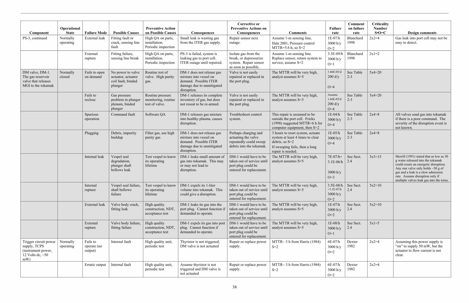
38
Component Operational
State Failure Mode Possible Causes Preventive Action on Possible Causes Consequences
Corrective or Preventive Actions on
Consequences Comments Failure
rate
Comment on failure
rate
Criticality Number S•O=C Design comments
PS-3, continued Normally operating
External leak Fitting fault or crack, sensing line fault
High QA on parts, installation. Periodic inspection
Small leak is wasting gas from the ITER gas supply.
Repair sensor next outage.
Assume 1-m sensing line, Hale 2001, Pressure control MTTR=5.6 h, so S=2
1E-07/h 3000 h/y O=2
Blanchard 1998
2x2=4 Gas leak into port cell may not be easy to detect.
External rupture
Fitting failure, sensing line break
High QA on parts, installation. Periodic inspection
PS-3 is failed, system is leaking gas to port cell. ITER outage until repaired.
Isolate gas from the break, or depressurize system. Repair sensor as soon as possible.
Assume 1-m sensing line. Replace sensor, return system to service, assume S=2
3.3E-09/h 3000 h/y O=1
Blanchard 1998
2x1=2
DM valve, DM-1. The gas reservoir valve that releases MGI to the tokamak
Normally closed
Fails to open on demand
No power to valve actuator, actuator coil fault, binded plunger
Routine test of valve. High purity gas.
DM-1 does not release gas mixture into vessel on demand. Possible ITER damage due to unmitigated disruption.
Valve is not easily repaired or replaced in the port plug.
The MTTR will be very high, analyst assumes S=5
1.66E-03/d
200 d/y O=4
See Table 2-3
5x4=20
Fails to reclose
Gas pressure problem in plunger plenum, binded plunger
Routine pressure monitoring, routine test of valve.
DM-1 releases its complete inventory of gas, but does not reseat to be re-armed.
Valve is not easily repaired or replaced in the port plug.
The MTTR will be very high, analyst assumes S=5
Assume
1.66E-03/d
200 d/y O=4
See Table 2-3
5x4=20
Spurious operation
Command fault Software QA DM-1 releases gas mixture into healthy plasma, causes disruption.
Troubleshoot control system.
This repair is assumed to be outside the port cell. Fricks (1998) suggested MTTR=6 h for computer equipment, then S=2
1E-04/h 3000 h/y O=4
See Table 2-3
2x4=8 All valves send gas into tokamak if there is a poor command. The severity of the disruption event is not known.
Plugging Debris, impurity buildup
Filter gas, use high purity gas
DM-1 does not release gas mixture into vessel on demand. Possible ITER damage due to unmitigated disruption.
Perhaps charging and actuating the valve repeatedly could sweep debris into the tokamak.
3 hours to reset system, actuate system at least 4 times to clear debris, so S=2 If sweeping fails, then a long repair is needed.
1E-05/h 3000 h/y O=4
See Table 2-3
2x4=8
Internal leak Vespel seal degradation, plunger shaft bellows leak
Test vespel to know its operating lifetime
DM-1 leaks small amount of gas into tokamak. This may or may not lead to disruption.
DM-1 would have to be taken out of service until port plug could be entered for replacement.
The MTTR will be very high, analyst assumes S=5
7E-07/h+ 3.1E-06/h 3000 h/y O=3
See Sect. 2.4
5x3=15 Merrill (1991) stated that as low as 30 g water released into the tokamak could create an energetic disruption. Any one valve only holds ~50 g of gas and a leak is a slow admission rate. Assume disruption only if multiple valves leak gas into the torus.
Internal rupture
Vespel seal failure, shaft bellows failure
Test vespel to know its operating lifetime
DM-1 expels its 1-liter volume into tokamak. This could give a disruption.
DM-1 would have to be taken out of service until port plug could be entered for replacement.
The MTTR will be very high, analyst assumes S=5
3.5E-08/h +3.1E-07/h
3000 h/y O=2
See Sect. 2.4
5x2=10
External leak Valve body crack, fitting leak
High quality construction, NDT, acceptance test
DM-1 leaks its gas into the port plug. Cannot function if demanded to operate.
DM-1 would have to be taken out of service until port plug could be entered for replacement.
The MTTR will be very high, analyst assumes S=5
1E-07/h 3000 h/y O=2
See Sect. 2.4
5x2=10
External rupture
Valve body failure, fitting failure
High quality construction, NDT, acceptance test
DM-1 expels its gas into port plug. Cannot function if demanded to operate.
DM-1 would have to be taken out of service until port plug could be entered for replacement.
The MTTR will be very high, analyst assumes S=5
1E-08/h 3000 h/y O=1
See Sect. 2.4
5x1=5
Trigger circuit power supply, TCPS (instrument power, 12 Volts dc, ~50 mW)
Normally operating
Fails to operate (no output)
Internal fault High quality unit, periodic test
Thyristor is not triggered, DM valve is not actuated
Repair or replace power supply.
MTTR~ 3 h from Harris (1984) S=2
6E-07/h 3000 h/y O=2
Dexter 1982
2x2=4 Assuming this power supply is “on” to supply 50 mW, but the actuator to flow current is not clear.
Erratic output Internal fault High quality unit, periodic test
Assume thyristor is not triggered and DM valve is not actuated
Repair or replace power supply.
MTTR~ 3 h from Harris (1984) S=2
6E-07/h 3000 h/y O=2
Dexter 1982
2x2=4
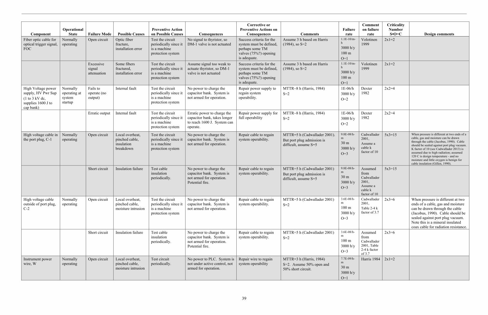
39
Component Operational
State Failure Mode Possible Causes Preventive Action on Possible Causes Consequences
Corrective or Preventive Actions on
Consequences Comments Failure
rate
Comment on failure
rate
Criticality Number S•O=C Design comments
Fiber optic cable for optical trigger signal, FOC
Normally operating
Open circuit Optic fiber fracture, installation error
Test the circuit periodically since it is a machine protection system
No signal to thyristor, so DM-1 valve is not actuated
Success criteria for the system must be defined, perhaps some TM valves (75%?) opening is adequate.
Assume 3 h based on Harris (1984), so S=2
1.1E-10/m-h
3000 h/y 100 m O=1
Volotinen 1999
2x1=2
Excessive signal attenuation
Some fibers fractured, installation error
Test the circuit periodically since it is a machine protection system
Assume signal too weak to actuate thyristor, so DM-1 valve is not actuated
Success criteria for the system must be defined, perhaps some TM valves (75%?) opening is adequate.
Assume 3 h based on Harris (1984), so S=2
1.1E-10/m-h
3000 h/y 100 m O=1
Volotinen 1999
2x1=2
High Voltage power supply, HV Pwr Sup (1 to 3 kV dc, supplies 1600 J to cap bank)
Normally operating at system startup
Fails to operate (no output)
Internal fault Test the circuit periodically since it is a machine protection system
No power to charge the capacitor bank. System is not armed for operation.
Repair power supply to regain system operability.
MTTR~8 h (Harris, 1984) S=2
1E-06/h 3000 h/y O=2
Dexter 1982
2x2=4
Erratic output Internal fault Test the circuit periodically since it is a machine protection system
Erratic power to charge the capacitor bank, takes longer to reach 1600 J. System can operate.
Repair power supply for full operability
MTTR~8 h (Harris, 1984) S=2
1E-06/h 3000 h/y O=2
Dexter 1982
2x2=4
High voltage cable in the port plug, C-1
Normally operating
Open circuit Local overheat, pinched cable, insulation breakdown
Test the circuit periodically since it is a machine protection system
No power to charge the capacitor bank. System is not armed for operation.
Repair cable to regain system operability.
MTTR=5 h (Cadwallader 2001). But port plug admission is difficult, assume S=5
9.8E-08/h-m
30 m 3000 h/y O=3
Cadwallader 2001, Assume a cable k factor of 10
5x3=15 When pressure is different at two ends of a cable, gas and moisture can be drawn through the cable (Jacobus, 1990). Cable should be sealed against port plug vacuum. K factor of 10 (see Cadwallader 2013) is assumed due to high radiation; assumed 120 C is design temperature - and no moisture and little oxygen is benign for cable insulation (Gillen, 1990).
Short circuit Insulation failure Test cable insulation periodically.
No power to charge the capacitor bank. System is not armed for operation. Potential fire.
Repair cable to regain system operability.
MTTR=5 h (Cadwallader 2001) But port plug admission is difficult, assume S=5
9.8E-08/h-m
30 m 3000 h/y O=3
Assumed from Cadwallader 2001, Assume a cable k factor of 10
5x3=15
High voltage cable outside of port plug, C-2
Normally operating
Open circuit Local overheat, pinched cable, moisture intrusion
Test the circuit periodically since it is a machine protection system
No power to charge the capacitor bank. System is not armed for operation.
Repair cable to regain system operability.
MTTR=5 h (Cadwallader 2001) S=2
3.6E-08/h-m
100 m 3000 h/y O=3
Cadwallader 2001, Table 2-4 k factor of 3.7
2x3=6 When pressure is different at two ends of a cable, gas and moisture can be drawn through the cable (Jacobus, 1990). Cable should be sealed against port plug vacuum. Note this is a mineral insulated coax cable for radiation resistance.
Short circuit Insulation failure Test cable insulation periodically.
No power to charge the capacitor bank. System is not armed for operation. Potential fire.
Repair cable to regain system operability.
MTTR=5 h (Cadwallader 2001) S=2
3.6E-08/h-m
100 m 3000 h/y O=3
Assumed from Cadwallader 2001, Table 2-4 k factor of 3.7
2x3=6
Instrument power wire, W
Normally operating
Open circuit Local overheat, pinched cable, moisture intrusion
Test circuit periodically.
No power to PLC. System is not under active control, not armed for operation.
Repair wire to regain system operability
MTTR=3 h (Harris, 1984) S=2. Assume 50% open and 50% short circuit.
7.7E-09/h-m
30 m 3000 h/y O=1
Harris 1984 2x1=2
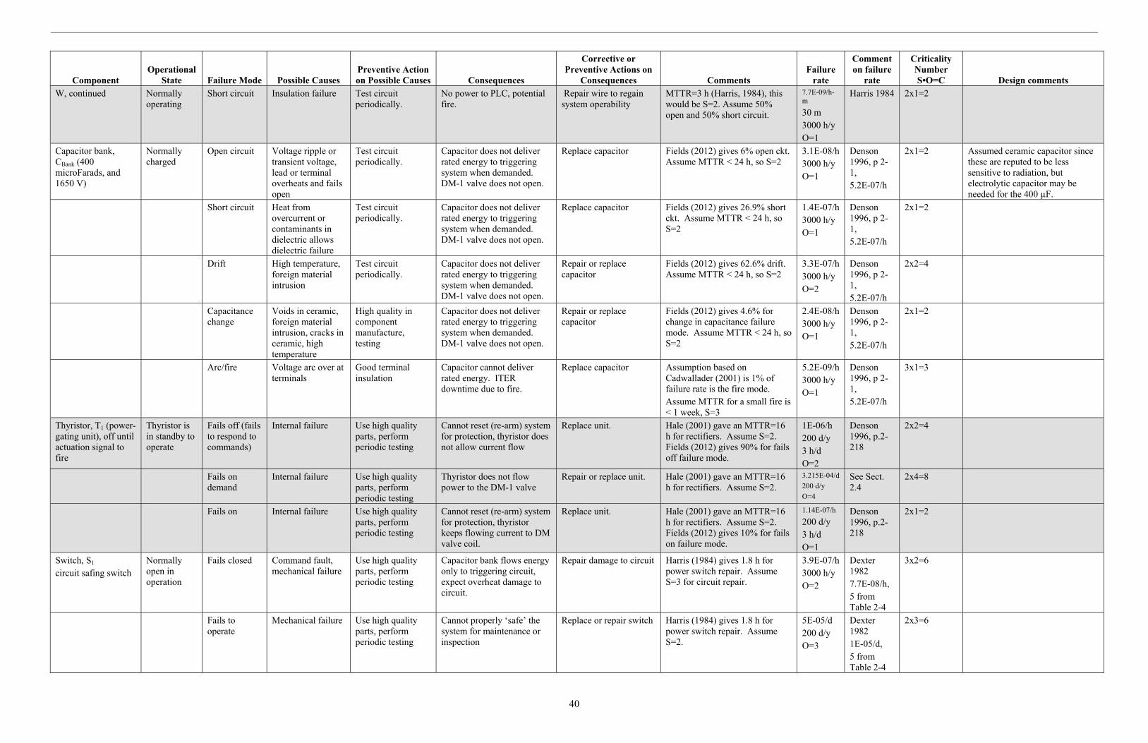
40
Component Operational
State Failure Mode Possible Causes Preventive Action on Possible Causes Consequences
Corrective or Preventive Actions on
Consequences Comments Failure
rate
Comment on failure
rate
Criticality Number S•O=C Design comments
W, continued Normally operating
Short circuit Insulation failure Test circuit periodically.
No power to PLC, potential fire.
Repair wire to regain system operability
MTTR=3 h (Harris, 1984), this would be S=2. Assume 50% open and 50% short circuit.
7.7E-09/h-m
30 m 3000 h/y O=1
Harris 1984 2x1=2
Capacitor bank, CBank (400 microFarads, and 1650 V)
Normally charged
Open circuit Voltage ripple or transient voltage, lead or terminal overheats and fails open
Test circuit periodically.
Capacitor does not deliver rated energy to triggering system when demanded. DM-1 valve does not open.
Replace capacitor Fields (2012) gives 6% open ckt. Assume MTTR < 24 h, so S=2
3.1E-08/h 3000 h/y O=1
Denson 1996, p 2-1, 5.2E-07/h
2x1=2 Assumed ceramic capacitor since these are reputed to be less sensitive to radiation, but electrolytic capacitor may be needed for the 400 µF.
Short circuit Heat from overcurrent or contaminants in dielectric allows dielectric failure
Test circuit periodically.
Capacitor does not deliver rated energy to triggering system when demanded. DM-1 valve does not open.
Replace capacitor Fields (2012) gives 26.9% short ckt. Assume MTTR < 24 h, so S=2
1.4E-07/h 3000 h/y O=1
Denson 1996, p 2-1, 5.2E-07/h
2x1=2
Drift High temperature, foreign material intrusion
Test circuit periodically.
Capacitor does not deliver rated energy to triggering system when demanded. DM-1 valve does not open.
Repair or replace capacitor
Fields (2012) gives 62.6% drift. Assume MTTR < 24 h, so S=2
3.3E-07/h 3000 h/y O=2
Denson 1996, p 2-1, 5.2E-07/h
2x2=4
Capacitance change
Voids in ceramic, foreign material intrusion, cracks in ceramic, high temperature
High quality in component manufacture, testing
Capacitor does not deliver rated energy to triggering system when demanded. DM-1 valve does not open.
Repair or replace capacitor
Fields (2012) gives 4.6% for change in capacitance failure mode. Assume MTTR < 24 h, so S=2
2.4E-08/h 3000 h/y O=1
Denson 1996, p 2-1, 5.2E-07/h
2x1=2
Arc/fire Voltage arc over at terminals
Good terminal insulation
Capacitor cannot deliver rated energy. ITER downtime due to fire.
Replace capacitor Assumption based on Cadwallader (2001) is 1% of failure rate is the fire mode. Assume MTTR for a small fire is < 1 week, S=3
5.2E-09/h 3000 h/y O=1
Denson 1996, p 2-1, 5.2E-07/h
3x1=3
Thyristor, T1 (power-gating unit), off until actuation signal to fire
Thyristor is in standby to operate
Fails off (fails to respond to commands)
Internal failure Use high quality parts, perform periodic testing
Cannot reset (re-arm) system for protection, thyristor does not allow current flow
Replace unit. Hale (2001) gave an MTTR=16 h for rectifiers. Assume S=2. Fields (2012) gives 90% for fails off failure mode.
1E-06/h 200 d/y 3 h/d O=2
Denson 1996, p.2-218
2x2=4
Fails on demand
Internal failure Use high quality parts, perform periodic testing
Thyristor does not flow power to the DM-1 valve
Repair or replace unit. Hale (2001) gave an MTTR=16 h for rectifiers. Assume S=2.
3.215E-04/d
200 d/y
O=4
See Sect. 2.4
2x4=8
Fails on Internal failure Use high quality parts, perform periodic testing
Cannot reset (re-arm) system for protection, thyristor keeps flowing current to DM valve coil.
Replace unit. Hale (2001) gave an MTTR=16 h for rectifiers. Assume S=2. Fields (2012) gives 10% for fails on failure mode.
1.14E-07/h
200 d/y 3 h/d O=1
Denson 1996, p.2-218
2x1=2
Switch, S1 circuit safing switch
Normally open in operation
Fails closed Command fault, mechanical failure
Use high quality parts, perform periodic testing
Capacitor bank flows energy only to triggering circuit, expect overheat damage to circuit.
Repair damage to circuit Harris (1984) gives 1.8 h for power switch repair. Assume S=3 for circuit repair.
3.9E-07/h 3000 h/y O=2
Dexter 1982 7.7E-08/h, 5 from Table 2-4
3x2=6
Fails to operate
Mechanical failure Use high quality parts, perform periodic testing
Cannot properly ‘safe’ the system for maintenance or inspection
Replace or repair switch Harris (1984) gives 1.8 h for power switch repair. Assume S=2.
5E-05/d 200 d/y O=3
Dexter 1982 1E-05/d, 5 from Table 2-4
2x3=6
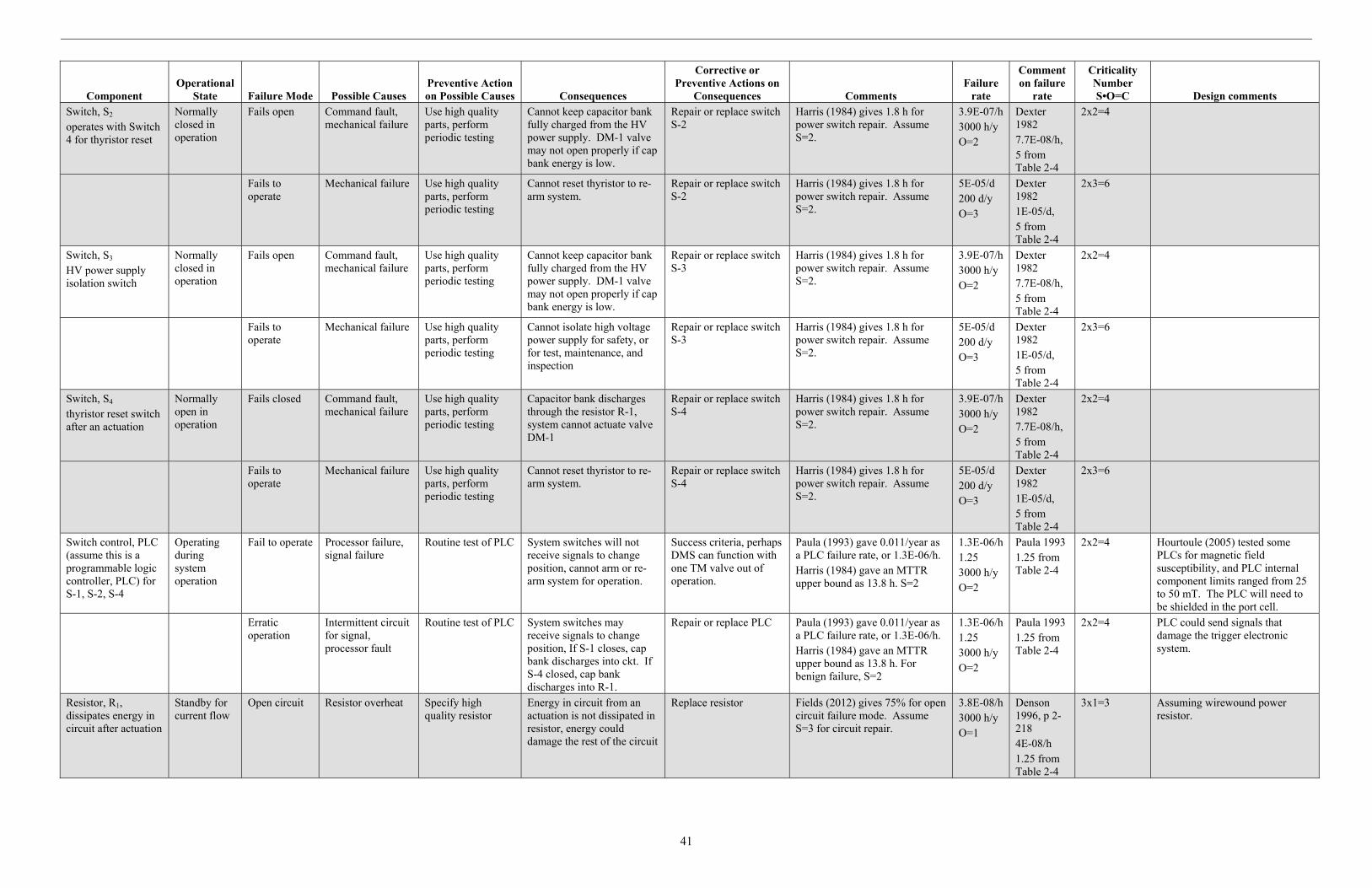
41
Component Operational
State Failure Mode Possible Causes Preventive Action on Possible Causes Consequences
Corrective or Preventive Actions on
Consequences Comments Failure
rate
Comment on failure
rate
Criticality Number S•O=C Design comments
Switch, S2 operates with Switch 4 for thyristor reset
Normally closed in operation
Fails open Command fault, mechanical failure
Use high quality parts, perform periodic testing
Cannot keep capacitor bank fully charged from the HV power supply. DM-1 valve may not open properly if cap bank energy is low.
Repair or replace switch S-2
Harris (1984) gives 1.8 h for power switch repair. Assume S=2.
3.9E-07/h 3000 h/y O=2
Dexter 1982 7.7E-08/h, 5 from Table 2-4
2x2=4
Fails to operate
Mechanical failure Use high quality parts, perform periodic testing
Cannot reset thyristor to re-arm system.
Repair or replace switch S-2
Harris (1984) gives 1.8 h for power switch repair. Assume S=2.
5E-05/d 200 d/y O=3
Dexter 1982 1E-05/d, 5 from Table 2-4
2x3=6
Switch, S3 HV power supply isolation switch
Normally closed in operation
Fails open Command fault, mechanical failure
Use high quality parts, perform periodic testing
Cannot keep capacitor bank fully charged from the HV power supply. DM-1 valve may not open properly if cap bank energy is low.
Repair or replace switch S-3
Harris (1984) gives 1.8 h for power switch repair. Assume S=2.
3.9E-07/h 3000 h/y O=2
Dexter 1982 7.7E-08/h, 5 from Table 2-4
2x2=4
Fails to operate
Mechanical failure Use high quality parts, perform periodic testing
Cannot isolate high voltage power supply for safety, or for test, maintenance, and inspection
Repair or replace switch S-3
Harris (1984) gives 1.8 h for power switch repair. Assume S=2.
5E-05/d 200 d/y O=3
Dexter 1982 1E-05/d, 5 from Table 2-4
2x3=6
Switch, S4 thyristor reset switch after an actuation
Normally open in operation
Fails closed Command fault, mechanical failure
Use high quality parts, perform periodic testing
Capacitor bank discharges through the resistor R-1, system cannot actuate valve DM-1
Repair or replace switch S-4
Harris (1984) gives 1.8 h for power switch repair. Assume S=2.
3.9E-07/h 3000 h/y O=2
Dexter 1982 7.7E-08/h, 5 from Table 2-4
2x2=4
Fails to operate
Mechanical failure Use high quality parts, perform periodic testing
Cannot reset thyristor to re-arm system.
Repair or replace switch S-4
Harris (1984) gives 1.8 h for power switch repair. Assume S=2.
5E-05/d 200 d/y O=3
Dexter 1982 1E-05/d, 5 from Table 2-4
2x3=6
Switch control, PLC (assume this is a programmable logic controller, PLC) for S-1, S-2, S-4
Operating during system operation
Fail to operate Processor failure, signal failure
Routine test of PLC System switches will not receive signals to change position, cannot arm or re-arm system for operation.
Success criteria, perhaps DMS can function with one TM valve out of operation.
Paula (1993) gave 0.011/year as a PLC failure rate, or 1.3E-06/h. Harris (1984) gave an MTTR upper bound as 13.8 h. S=2
1.3E-06/h 1.25 3000 h/y O=2
Paula 1993 1.25 from Table 2-4
2x2=4 Hourtoule (2005) tested some PLCs for magnetic field susceptibility, and PLC internal component limits ranged from 25 to 50 mT. The PLC will need to be shielded in the port cell.
Erratic operation
Intermittent circuit for signal, processor fault
Routine test of PLC System switches may receive signals to change position, If S-1 closes, cap bank discharges into ckt. If S-4 closed, cap bank discharges into R-1.
Repair or replace PLC Paula (1993) gave 0.011/year as a PLC failure rate, or 1.3E-06/h. Harris (1984) gave an MTTR upper bound as 13.8 h. For benign failure, S=2
1.3E-06/h 1.25 3000 h/y O=2
Paula 1993 1.25 from Table 2-4
2x2=4 PLC could send signals that damage the trigger electronic system.
Resistor, R1, dissipates energy in circuit after actuation
Standby for current flow
Open circuit Resistor overheat Specify high quality resistor
Energy in circuit from an actuation is not dissipated in resistor, energy could damage the rest of the circuit
Replace resistor Fields (2012) gives 75% for open circuit failure mode. Assume S=3 for circuit repair.
3.8E-08/h 3000 h/y O=1
Denson 1996, p 2-218 4E-08/h 1.25 from Table 2-4
3x1=3 Assuming wirewound power resistor.

42
Component Operational
State Failure Mode Possible Causes Preventive Action on Possible Causes Consequences
Corrective or Preventive Actions on
Consequences Comments Failure
rate
Comment on failure
rate
Criticality Number S•O=C Design comments
R1, continued Standby for current flow
Drift Too many heatup and cooldown cycles.
Specify margin in resistor cycles
Energy in circuit from an actuation is slow to dissipate in resistor, take more than 3 hours to reset the system.
Replace resistor Fields (2012) gives 10% for drift failure mode. Assume S=2 for resistor replacement.
5E-09/h 3000 h/y O=1
Denson 1996, p2-218 4E-08/h 1.25 from Table 2-4
2x1=2
Mechanical failure
Resistor impacted or struck, debonding
Protect resistor in a cabinet or enclosure, specify high quality resistor
Energy in circuit from an actuation is not dissipated in resistor, energy could damage the rest of the circuit
Replace resistor Fields (2012) gives 10% for mechanical failure. Assume S=3 for circuit repair.
5E-09/h 3000 h/y O=1
Denson 1996, p2-218 4E-08/h 1.25 from Table 2-4
3x1=3
Short circuit Resistor overheat Specify high quality resistor
Energy in circuit from an actuation is quickly dissipated in resistor, the energy release will damage the area surrounding the rest of the circuit
Replace resistor Fields (2012) gives 5% for shorted failure mode. Assume S=3 for cleanup and resistor replacement
2.5E-09/h 3000 h/y O=1
Denson 1996, p2-218 4E-08/h 1.25 from Table 2-4
3x1=3
Diode, D1 one-direction flow prevents current oscillation in the circuit when ckt is actuated
Standby component for one-direction current flow
Short circuit Degraded unit, loss of reverse blocking ability
Specify high quality power diode
Current in circuit could flow in reverse direction, current oscillation in circuit leading to circuit damage. DM-1 will not reset.
Replace diode, repair circuit.
Fields (2012) gives 48.3% for high power diode shorted failure mode. Assume S=3 for cleanup and diode replacement
8.5E-08/h 3000 h/y O=1
Denson 1996, p 2-12 1.4E-07/h 1.25 from Table 2-4
3x1=3
Open circuit Overheat leading to wire melt
Specify high quality power diode
Circuit will function to actuate DM-1 valve, but will not reset the thyristor
Replace diode Fields (2012) gives 44.8% for opened failure mode. Assume S=2 for diode replacement
7.8E-08/h 3000 h/y O=1
Denson 1996, p 2-12 1.4E-07/h 1.25 from Table 2-4
2x1=2
Drift Parameter change by overstress, reversed polarity
Specify high quality power diode
Circuit will still function, may take more than 3 hours to reset system.
Replace diode to restore system operability
Fields (2012) gives 6.9% for drift failure mode. Assume S=2 for diode replacement
1.2E-08/h 3000 h/y O=1
Denson 1996, p 2-12 1.4E-07/h 1.25 from Table 2-4
2x1=2

43