Embed Size (px)
Citation preview
Preliminary Design Review
May 7, 2002Space System Product Development Class
Department of Aeronautics & Astronautics, MITElectro Magnetic Formation Flight Of Rotating
Clustered Entities
5/24/2002 CDIO3 Class Project 2
Introduction
Geeta Gupta
Introduction•Mission•Background &Motivation•RequirementsSummary•Approach•PDR Purpose•Overview
SubsystemsOperationsImplementationConclusion
5/24/2002 CDIO3 Class Project 3
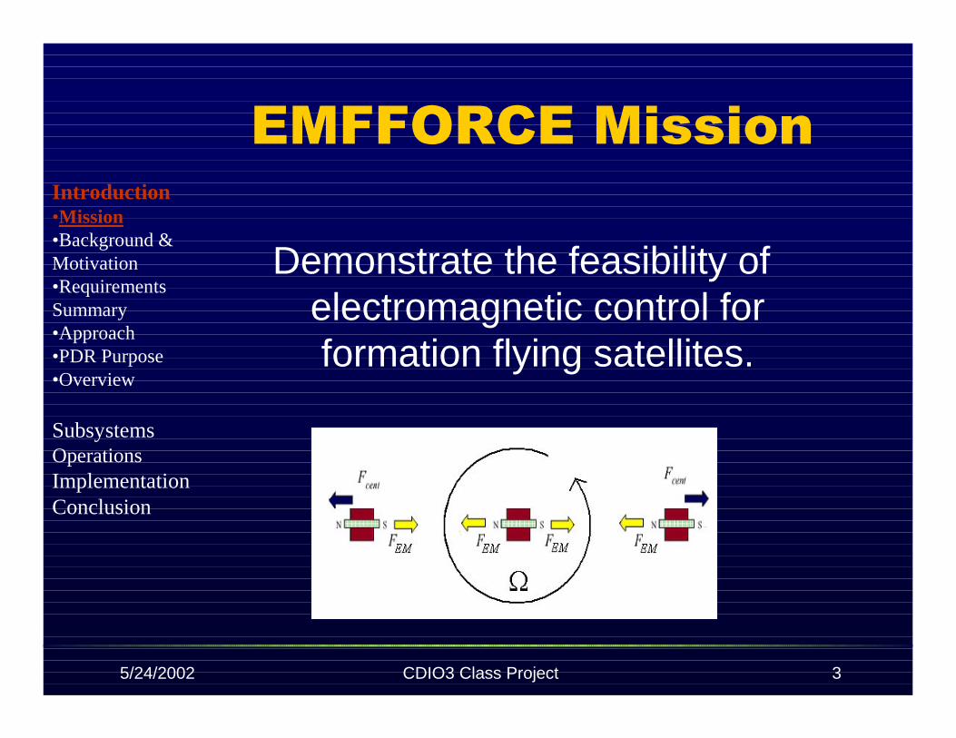
EMFFORCE Mission
Demonstrate the feasibility ofelectromagnetic control forformation flying satellites.
Introduction•Mission•Background &Motivation•RequirementsSummary•Approach•PDR Purpose•Overview
SubsystemsOperationsImplementationConclusion

5/24/2002 CDIO3 Class Project 4
Definition of Formation Flight
A cluster of cooperating satellitesflying in a desired formation.
Introduction•Mission•Background &Motivation•RequirementsSummary•Approach•PDR Purpose•Overview
SubsystemsOperationsImplementationConclusion
5/24/2002 CDIO3 Class Project 5
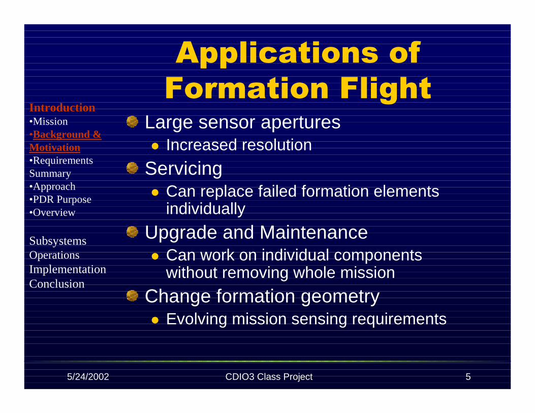
Applications of Formation Flight
Large sensor aperturesIncreased resolution
ServicingCan replace failed formation elementsindividually
Upgrade and MaintenanceCan work on individual componentswithout removing whole mission
Change formation geometryEvolving mission sensing requirements
Introduction•Mission•Background &Motivation•RequirementsSummary•Approach•PDR Purpose•Overview
SubsystemsOperationsImplementationConclusion

5/24/2002 CDIO3 Class Project 6
Advantages of Formation Flight
Large baselines to improve angularresolutionSmaller vehicles
Ease of packaging, launch and deployment
RedundancyMission does not fail if one satellite fails
ReconfigurableReplace individual space craftCan integrate new technology during mission
Introduction•Mission•Background &Motivation•RequirementsSummary•Approach•PDR Purpose•Overview
SubsystemsOperationsImplementationConclusion

5/24/2002 CDIO3 Class Project 7
Challenges of Formation Flight
Command and ControlControl multiple vehicles’ absolutepositions/motion vs.. relativepositions/motion
Propellant DrawbacksFuel limits lifetimeExhaust particulates contaminateimaging instrumentsExhaust creates haze which limitsimaging
Introduction•Mission•Background &Motivation•RequirementsSummary•Approach•PDR Purpose•Overview
SubsystemsOperationsImplementationConclusion

5/24/2002 CDIO3 Class Project 8
Definition of Electromagnetic Control
Implement electromagnetic dipoles tocreate forces and torques between thevehiclesDipoles can be controlled by varying theamount of current through theelectromagnet coil.
Can provide steady forces and torques formaneuverabilityCan provide disturbance rejection for moreprecise control
Introduction•Mission•Background &Motivation•RequirementsSummary•Approach•PDR Purpose•Overview
SubsystemsOperationsImplementationConclusion
5/24/2002 CDIO3 Class Project 9
Advantages of EMFF
No thrustersFewer consumables Longer life
Zero pollutionNo contact contamination
No radiative contamination
Controls relative position/motionvs.. absolute position/motion
Introduction•Mission•Background &Motivation•RequirementsSummary•Approach•PDR Purpose•Overview
SubsystemsOperationsImplementationConclusion

5/24/2002 CDIO3 Class Project 10
Challenges of EMFF
Control ProblemUnstable – not unique to EMFFCoupled control
Each vehicles’ motion affects all other vehicles
Electromagnet DrawbacksFerromagnetic material is heavyElectromagnetic force is weak
Force in the far-field drops of as the 4th powerof separation distance
Electromagnetic interference with otherelectronic subsystems
Introduction•Mission•Background &Motivation•RequirementsSummary•Approach•PDR Purpose•Overview
SubsystemsOperationsImplementationConclusion

5/24/2002 CDIO3 Class Project 11
Customer RequirementsMultiple VehiclesRepresentative Formation FlyingVehiclesControl to replace thrustersControl three degrees of freedom(DOF), traceable to six DOFRobust controller
Disturbance rejectionReposition vehicles
Introduction•Mission•Background &Motivation•RequirementsSummary•Approach•PDR Purpose•Overview
SubsystemsOperationsImplementationConclusion
5/24/2002 CDIO3 Class Project 12
ConstraintsScheduleBudgetLimited human resources to CDIOclass and staffTesting facilityNo use of umbilical resources; power,air supply, communicationsRecorded test dataSafety of people, facility, and system
Introduction•Mission•Background &Motivation•RequirementsSummary•Approach•PDR Purpose•Overview
SubsystemsOperationsImplementationConclusion

5/24/2002 CDIO3 Class Project 13
System Functional Requirements
Musts:Stability with at least three vehiclesControl in each relative DOF
Shoulds:Representative 5 rotation maneuver
One rotation spin-up, 3 rotations steady state,and one rotation spin-down
Operate in the far fieldSeparation distance at least 10x length ofelectro-magnet
Introduction•Mission•Background &Motivation•RequirementsSummary•Approach•PDR Purpose•Overview
SubsystemsOperationsImplementationConclusion

5/24/2002 CDIO3 Class Project 14
System Operational Requirements
Test time 5 minutes
Identical interchangeable vehiclesSend/record test data
Respond to other satellitesRespond to user input
Demonstrate autonomyMaintain safety
Introduction•Mission•Background &Motivation•RequirementsSummary•Approach•PDR Purpose•Overview
SubsystemsOperationsImplementationConclusion

5/24/2002 CDIO3 Class Project 15
EMFFORCE Testbed Development ApproachConceive and Design EMFFORCEtestbed PDR May 7, 2002Implement testbed CDR Nov.,2002
Operate completed testbed ARMarch, 2003
Operate at MITOperate at Lockheed Flat Floor Facility inDenver
Introduction•Mission•Background &Motivation•RequirementsSummary•Approach•PDR Purpose•Overview
SubsystemsOperationsImplementationConclusion

5/24/2002 CDIO3 Class Project 16
PDR Purpose
To review the preliminary designand identify and resolve high riskelements of the system.Have outside expert review ofcurrent progress.
Introduction•Mission•Background &Motivation•RequirementsSummary•Approach•PDR Purpose•Overview
SubsystemsOperationsImplementationConclusion

5/24/2002 CDIO3 Class Project 17
Space System Product Development Class
Actuation Formation Flight SystemsJesus Bolivar Amilio Aviles Amilio AvilesWilliam Fournier Andre’ Bosch Jesus BolivarLindsey Wolf Oscar Murillo Geeta GuptaMelanie Woo Leah Soffer
Electronics Structure/PowerStephanie Slowik Geeta GuptaErik Stockham Amy SchonsheckMaggie Sullivan Timothy SutherlandJennifer Underwood
5/24/2002 CDIO3 Class Project 18
OverviewSub-System design
ActuationFormation FlightElectronicsStructure/Power
OperationsImplementation
Resource TrackingBudgetsVerification & ValidationSchedulesAction Items
Conclusion
Introduction•Mission•Background &Motivation•RequirementsSummary•Approach•Overview
SubsystemsOperationsImplementationConclusion
5/24/2002 CDIO3 Class Project 19
Actuation
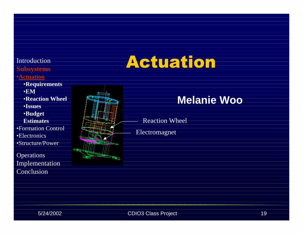
Melanie Woo
Electromagnet
Reaction Wheel
IntroductionSubsystems•Actuation
•Requirements•EM•Reaction Wheel•Issues•BudgetEstimates
•Formation Control•Electronics•Structure/Power
OperationsImplementationConclusion

5/24/2002 CDIO3 Class Project 20
ActuationEM force induces spin-up of cluster frominitial perpendicular orientationRW provides counter torque to balancemoments induced by electromagnets
IntroductionSubsystems•Actuation
•Requirements•EM•Reaction Wheel•Issues•BudgetsEstimates
•Formation Control•Electronics•Structure/Power
OperationsImplementationConclusion
5/24/2002 CDIO3 Class Project 21
Actuation Requirements
Actuate control of vehicle clusterMagnets must be controllable innecessary DOFNo thrusters may be used
Electromagnets provide forceReaction wheel provides torque
Minimize mass and powerconsumption
IntroductionSubsystems•Actuation
•Requirements•EM•Reaction Wheel•Issues•BudgetEstimates
•Formation Control•Electronics•Structure/Power
OperationsImplementationConclusion

5/24/2002 CDIO3 Class Project 22
Trades – EM Configuration
Possible configurations:Dipole, Y-pole, L-pole, X-pole
Eliminate:L-pole: center of mass problemX-pole: mass distribution to 4 dipole legs
IntroductionSubsystems•Actuation
•Requirements•EM
•Trades•Design
•Reaction Wheel•Issues•BudgetEstimates
•Formation Control•Electronics•Structure/Power
OperationsImplementationConclusion
Minimize mass and powerconsumption
IntroductionSubsystems•Actuation
•Requirements

5/24/2002 CDIO3 Class Project 23
Dipole vs.. Y-pole
•Design•Reaction Wheel•Issues•BudgetEstimates
•Formation Control•Electronics•Structure/Power
OperationsImplementationConclusion
Introduction
Trades – EM Configuration
Considerations:Mass distribution: Force
Dipole generates greater force since itenergizes larger amount of core massY-pole can vary direction of magnetic fieldwithout being rotated by reaction wheel
TorqueY-pole generates additional torque to becountered by reaction wheel
Subsystems•Actuation
•Requirements•EM
•Trades

5/24/2002 CDIO3 Class Project 24
Trades – EM Core Material
CostAvailabilityMagneticProperties
B-H curveBsaturation
Permeability
Steel vs.. Iron
EM Core MaterialInduced Field vs. Applied Field
0
0.5
1
1.5
2
2.5
0 5000 10000 15000 20000 25000 30000 35000
H [Amps/m]
B[T
esla
]
AISI 1010 steel Remko soft pure iron
IntroductionSubsystems•Actuation
•Requirements•EM
•Trades•Design
•Reaction Wheel•Issues•BudgetEstimates
•Formation Control•Electronics•Structure/Power
OperationsImplementationConclusion

5/24/2002 CDIO3 Class Project 25
ModelingEM Software:Infolytica MagNet
Input EM configuration andgeometry to obtain forcesand torques
Example:Y-pole configurationSeparation: 2 mCore mass: 19.5 kgApplied current: 10 Amps
IntroductionSubsystems•Actuation
•Requirements•EM
•Trades•Design
•Reaction Wheel•Issues•BudgetEstimates
•Formation Control•Electronics•Structure/Power
OperationsImplementationConclusion

5/24/2002 CDIO3 Class Project 26
Modeling
Results:Force on A andB equal
Magnitude:0.42 N
Torque greateron B than A
A: 0.052 N-mB: 0.848 N-m
A
B
Energized CoilsIntroductionSubsystems•Actuation
•Requirements•EM
•Trades•Design
•Reaction Wheel•Issues•BudgetEstimates
•Formation Control•Electronics•Structure/Power
OperationsImplementationConclusion

5/24/2002 CDIO3 Class Project 27
Test Run VideoIntroductionSubsystems•Actuation
•Requirements•EM
•Trades•Design
•Reaction Wheel•Issues•BudgetEstimates
•Formation Control•Electronics•Structure/Power
OperationsImplementationConclusion
5/24/2002 CDIO3 Class Project 28
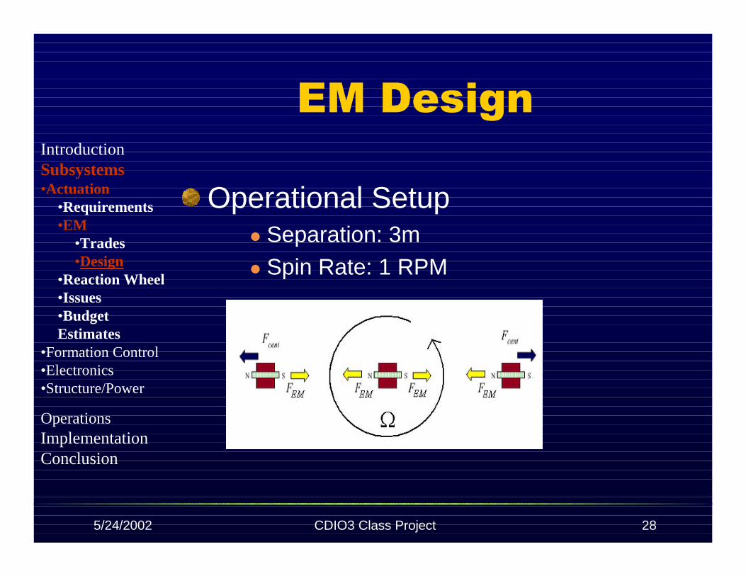
EM Design
Operational SetupSeparation: 3mSpin Rate: 1 RPM
IntroductionSubsystems•Actuation
•Requirements•EM
•Trades•Design
•Reaction Wheel•Issues•BudgetEstimates
•Formation Control•Electronics•Structure/Power
OperationsImplementationConclusion

5/24/2002 CDIO3 Class Project 29
EM Design
Magnetic Force for ThreeVehicles
Set equal to centripetal force
44 )(2
3
)2
(2
3
ssF CAoBAo
mag πµµµ
π
µµµ +=
totcent ms
F )2
(2Ω=
IntroductionSubsystems•Actuation
•Requirements•EM
•Trades•Design
•Reaction Wheel•Issues•BudgetEstimates
•Formation Control•Electronics•Structure/Power
OperationsImplementationConclusion

5/24/2002 CDIO3 Class Project 30
EM Design
Substituting in the followingrelations
And solving for mcore
coreo
core
o
coreCBA
BmBV
ρµµµµµ ====
51
5sm
Bm ototcore
core
πµρΩ=
IntroductionSubsystems•Actuation
•Requirements•EM
•Trades•Design
•Reaction Wheel•Issues•BudgetEstimates
•Formation Control•Electronics•Structure/Power
OperationsImplementationConclusion
5/24/2002 CDIO3 Class Project 31
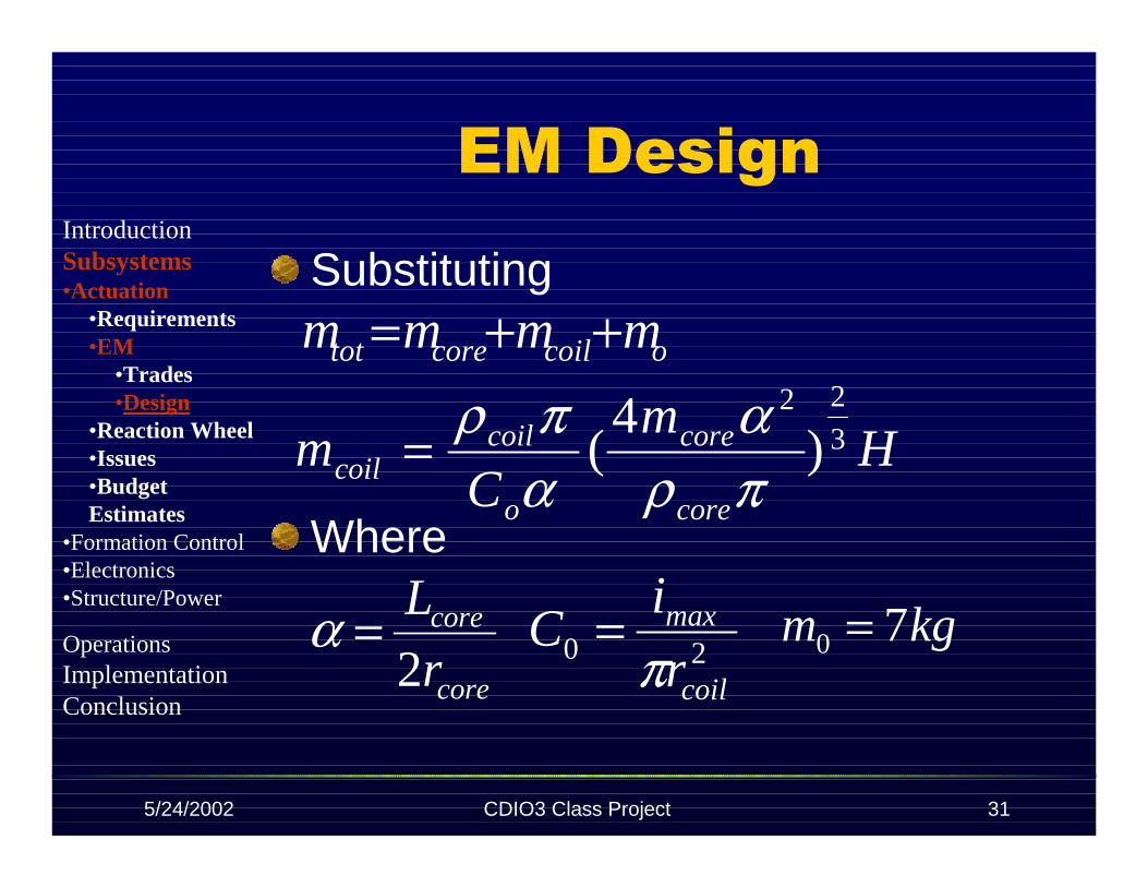
EM Design
Substituting
Where
ocoilcoretot mmmm ++=
kgm 70 =
Hm
Cm
core
core
o
coilcoil
3
22
)4
(πρα
απρ=
core
core
r
L
2=α 20
coil
max
r
iC
π=
IntroductionSubsystems•Actuation
•Requirements•EM
•Trades•Design
•Reaction Wheel•Issues•BudgetEstimates
•Formation Control•Electronics•Structure/Power
OperationsImplementationConclusion

5/24/2002 CDIO3 Class Project 32
EM DesignSubstituting
B = 2 Tesla
α = 10H = 20000
Solving numerically for mcore yieldsmcore = 6.5 kg
Solving for core dimensionsLcore = .47mrcore = .02m
IntroductionSubsystems•Actuation
•Requirements•EM
•Trades•Design
•Reaction Wheel•Issues•BudgetEstimates
•Formation Control•Electronics•Structure/Power
OperationsImplementationConclusion
5/24/2002 CDIO3 Class Project 33
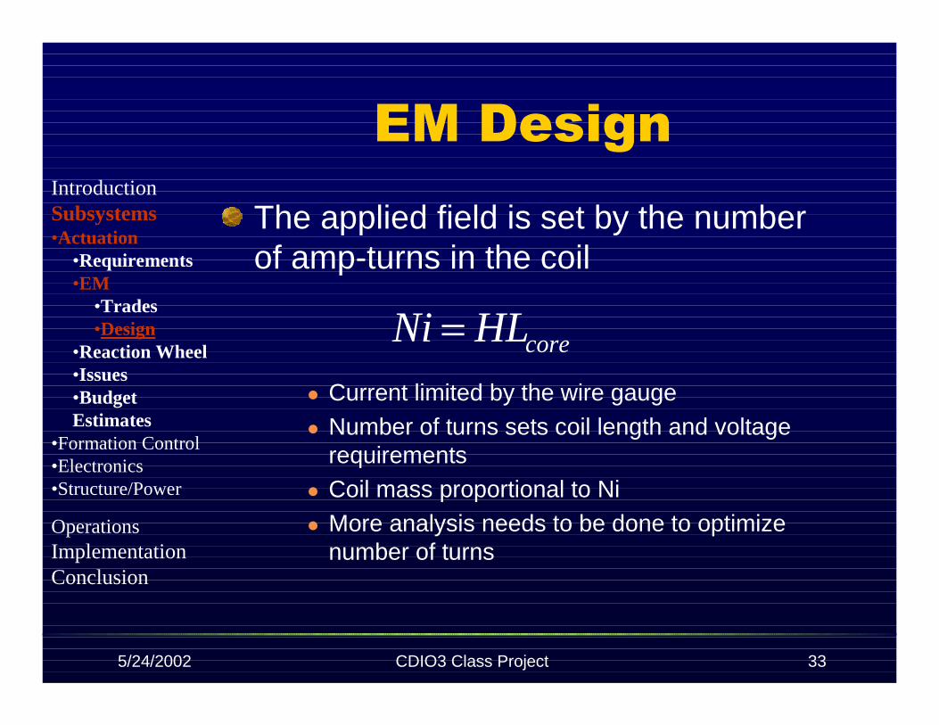
EM DesignThe applied field is set by the numberof amp-turns in the coil
Current limited by the wire gaugeNumber of turns sets coil length and voltagerequirementsCoil mass proportional to NiMore analysis needs to be done to optimizenumber of turns
coreHLNi =
IntroductionSubsystems•Actuation
•Requirements•EM
•Trades•Design
•Reaction Wheel•Issues•BudgetEstimates
•Formation Control•Electronics•Structure/Power
OperationsImplementationConclusion

5/24/2002 CDIO3 Class Project 34
RW Trades
Build vs.. BuyWill build RW to specifications
CheaperCommercial RWs are spacecraft sized
Material: Steel vs.. Aluminum vs..Plastic
Use AluminumDoesn’t interfere with magnetic fieldHigher density than plastics – RW will nothave to be as large
IntroductionSubsystems•Actuation
•Requirements•EM•Reaction Wheel
•Trades•Design
•Issues•BudgetEstimates
•Formation Control•Electronics•Structure/Power
OperationsImplementationConclusion

5/24/2002 CDIO3 Class Project 35
System Assumptions for RW Analysis
Cluster contains two vehiclesVehicles are modeled as uniform densitycylindersMax ΩRW = 2000 rpm ~ 210 rad/sRW is modeled as a ring with a thin platein the centerRing has square cross section withdiameter tring
rRWtring
IntroductionSubsystems•Actuation
•Requirements•EM•Reaction Wheel
•Trades•Design
•Issues•BudgetEstimates
•Formation Control•Electronics•Structure/Power
OperationsImplementationConclusion

5/24/2002 CDIO3 Class Project 36
System Dynamics
RWs provides counter torque tobalance system:
Cluster angular momentum(Hcluster):
Cluster moment of inertia (I):
Ω= IH cluster
clusterRW HH −=2
+=
2
0 22
smII tot
IntroductionSubsystems•Actuation
•Requirements•EM•Reaction Wheel
•Trades•Design
•Issues•BudgetEstimates
•Formation Control•Electronics•Structure/Power
OperationsImplementationConclusion
5/24/2002 CDIO3 Class Project 37
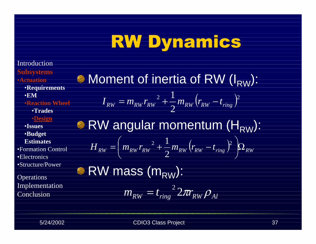
RW Dynamics
Moment of inertia of RW (IRW):
RW angular momentum (HRW):
RW mass (mRW):
( )22
2
1ringRWRWRWRWRW trmrmI −+=
( ) RWringRWRWRWRWRW trmrmH Ω
−+= 22
2
1
AlRWringRW rtm ρπ22=
IntroductionSubsystems•Actuation
•Requirements•EM•Reaction Wheel
•Trades•Design
•Issues•BudgetEstimates
•Formation Control•Electronics•Structure/Power
OperationsImplementationConclusion
5/24/2002 CDIO3 Class Project 38
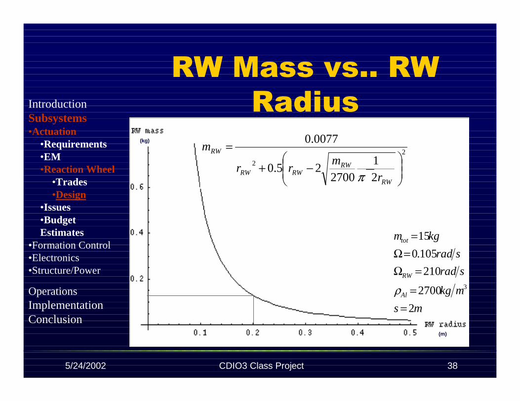
RW Mass vs.. RW Radius
ms
mkg
sradrpm
sradrpm
kgm
Al
RW
tot
2
2700
2102000
105.01
15
3
==
==Ω==Ω
=
ρ
(kg)
(m)
ms
mkg
srad
srad
kgm
Al
RW
tot
2
2700
210
105.0
15
3
==
=Ω=Ω
=
ρ
2
2
2
21
270025.0
0077.0
−+
=
RW
RWRWRW
RW
r
mrr
m
π
IntroductionSubsystems•Actuation
•Requirements•EM•Reaction Wheel
•Trades•Design
•Issues•BudgetEstimates
•Formation Control•Electronics•Structure/Power
OperationsImplementationConclusion

5/24/2002 CDIO3 Class Project 39
RW Mass Estimate
RW has a mass of 0.16 kg givena radius of 0.2 mRW Assembly will not exceed 1kg - includes motor
IntroductionSubsystems•Actuation
•Requirements•EM•Reaction Wheel
•Trades•Design
•Issues•BudgetEstimates
•Formation Control•Electronics•Structure/Power
OperationsImplementationConclusion

5/24/2002 CDIO3 Class Project 40
RW Power Analysis
RW uses power mainly whenapplying torque – during spin up
Torque induced by dipole (τmag):
Relationship for B-field:
RWmagRWP Ω= τ
BAmag ×= µτ
30
2 xB Bµ
πµ=
IntroductionSubsystems•Actuation
•Requirements•EM•Reaction Wheel
•Trades•Design
•Issues•BudgetEstimates
•Formation Control•Electronics•Structure/Power
OperationsImplementationConclusion
5/24/2002 CDIO3 Class Project 41
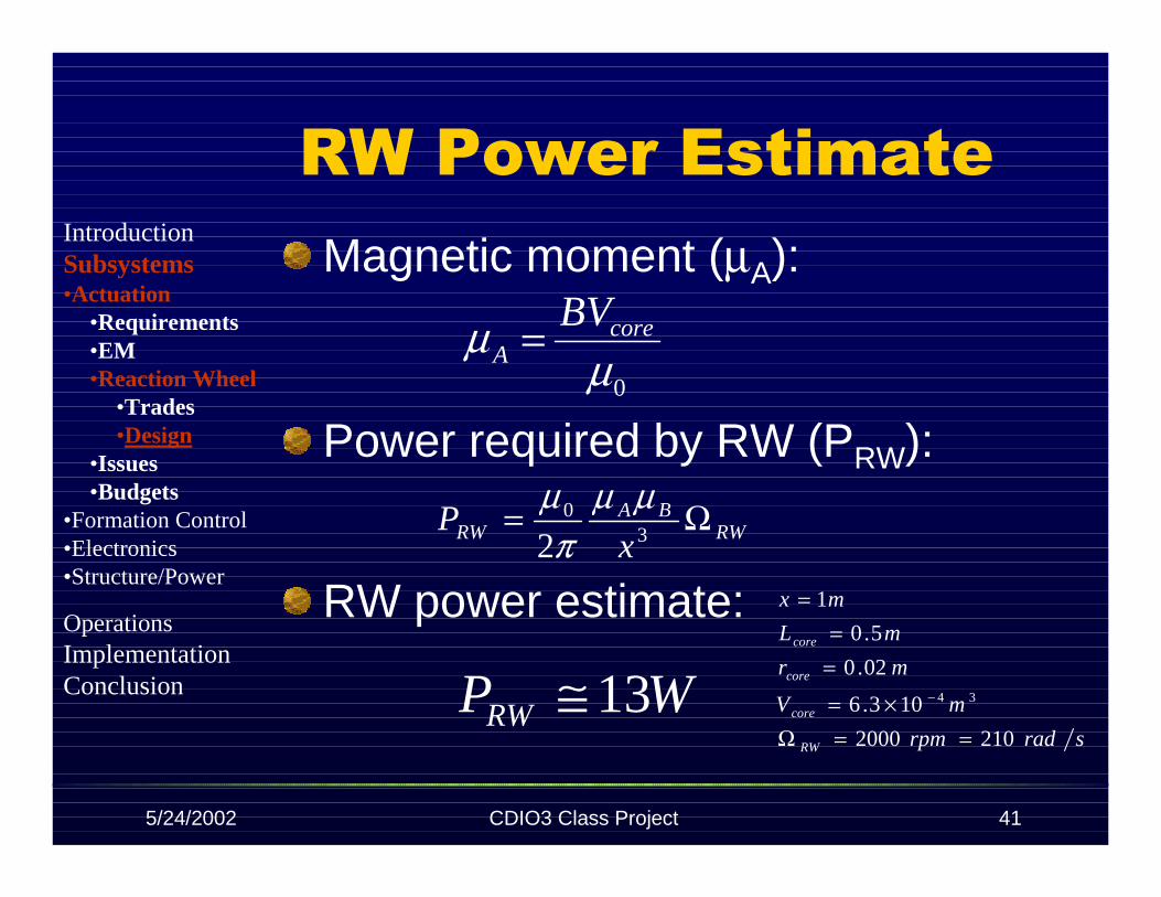
RW Power EstimateMagnetic moment (µA):
Power required by RW (PRW):
RW power estimate:
RWBA
RW xP Ω=
30
2
µµπ
µ
sradrpm
mV
mr
mL
mx
RW
core
core
core
2102000
103.6
02.0
5.0
1
34
==Ω×=
==
=
−WPRW 13≅
0µµ core
A
BV=
IntroductionSubsystems•Actuation
•Requirements•EM•Reaction Wheel
•Trades•Design
•Issues•Budgets
•Formation Control•Electronics•Structure/Power
OperationsImplementationConclusion

5/24/2002 CDIO3 Class Project 42
Actuation Issues
System may not be able tooperate in the far fieldTotal mass is large (~15 kg)
Magnet core mass increasesrapidly with vehicle mass
Magnet temperature must bemonitored during operation
IntroductionSubsystems•Actuation
•Requirements•EM•Reaction Wheel•Issues•BudgetEstimates
•Formation Control•Electronics•Structure/Power
OperationsImplementationConclusion

5/24/2002 CDIO3 Class Project 43
Budgets Estimates
1.550CopperWire
1331339911501150TotalTotal(vehicle)(vehicle)
1000
100
Cost($US)
131RWAssembly
>1206.5Iron Core
Power (W)Mass (kg)Part
IntroductionSubsystems•Actuation
•Requirements•EM•Reaction Wheel•Issues•BudgetEstimates
•Formation Control•Electronics•Structure/Power
OperationsImplementationConclusion

5/24/2002 CDIO3 Class Project 44
Control
Will Fournier
Control
IntroductionSubsystems•Actuation•Formation Control
•Control•Requirements•Design•Trades•Issues•BudgetsEstimates
•Metrology•Electronics•Structure/Power
OperationsImplementationConclusion

5/24/2002 CDIO3 Class Project 45
RequirementsCounteract disturbancesReposition satellites to performmaneuvers
One rotation spin-upThree rotations steady stateOne rotation spin-down
Control tolerance to 1/10separation distance
IntroductionSubsystems•Actuation•Formation Control
•Control•Requirements•Design•Trades•Issues•BudgetsEstimates
•Metrology•Electronics•Structure/Power
OperationsImplementationConclusion
5/24/2002 CDIO3 Class Project 46
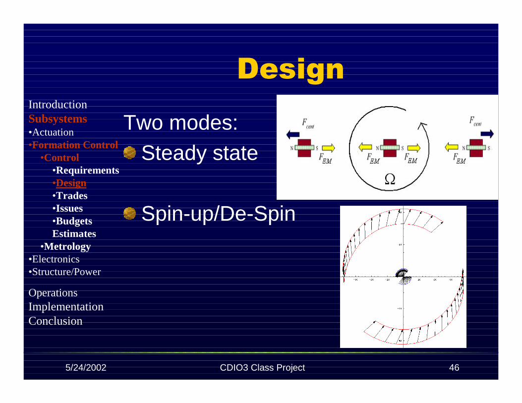
Design
Two modes:Steady state
Spin-up/De-Spin
IntroductionSubsystems•Actuation•Formation Control
•Control•Requirements•Design•Trades•Issues•BudgetsEstimates
•Metrology•Electronics•Structure/Power
OperationsImplementationConclusion

5/24/2002 CDIO3 Class Project 47
Steady State
Must model axial dynamics
IntroductionSubsystems•Actuation•Formation Control
•Control•Requirements•Design•Trades•Issues•BudgetsEstimates
•Metrology•Electronics•Structure/Power
OperationsImplementationConclusion
5/24/2002 CDIO3 Class Project 48
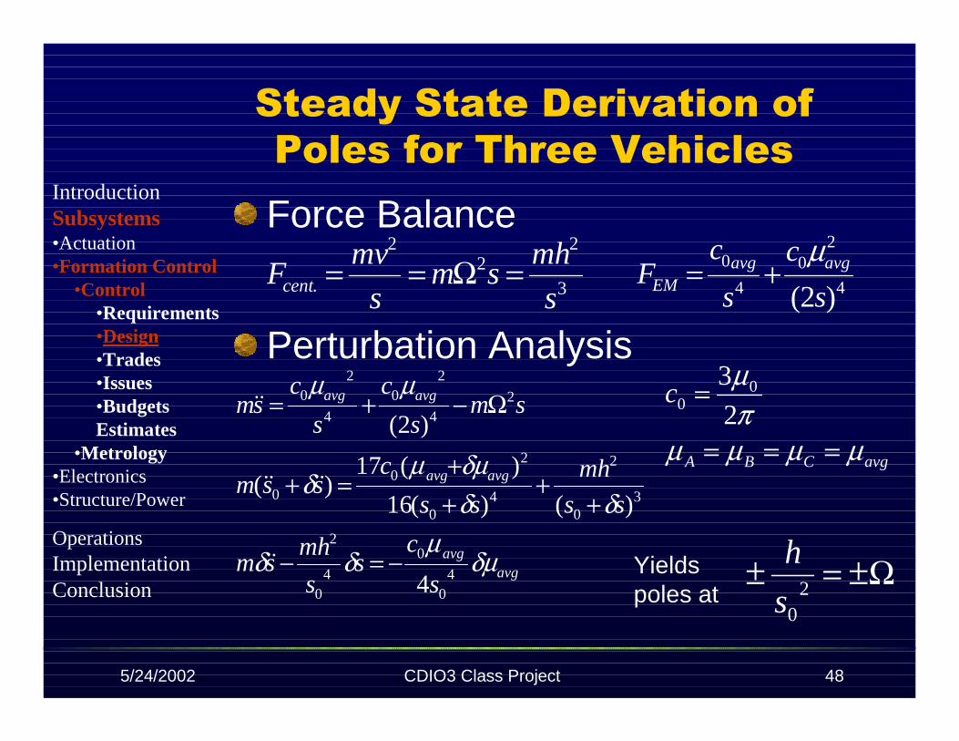
Steady State Derivation of Poles for Three VehiclesForce Balance
avgavg
avgavg
avgavg
s
cs
s
mhsm
ss
mh
ss
cssm
sms
c
s
csm
δµµ
δδ
δδδµµ
δ
µµ
40
0
40
2
30
2
40
20
0
24
20
4
20
4
)()(16
)(17)(
)2(
−=−
++
++
=+
Ω−+=
&&
&&&&
&&
avgCBA
c
µµµµπµ
===
=2
3 00
3
22
2
. s
mhsm
s
mvFcent =Ω== 4
20
4
0
)2( s
c
s
cF avgavg
EM
µ+=
Ω±=± 20s
hYieldspoles at
Perturbation Analysis
IntroductionSubsystems•Actuation•Formation Control
•Control•Requirements•Design•Trades•Issues•BudgetsEstimates
•Metrology•Electronics•Structure/Power
OperationsImplementationConclusion
5/24/2002 CDIO3 Class Project 49
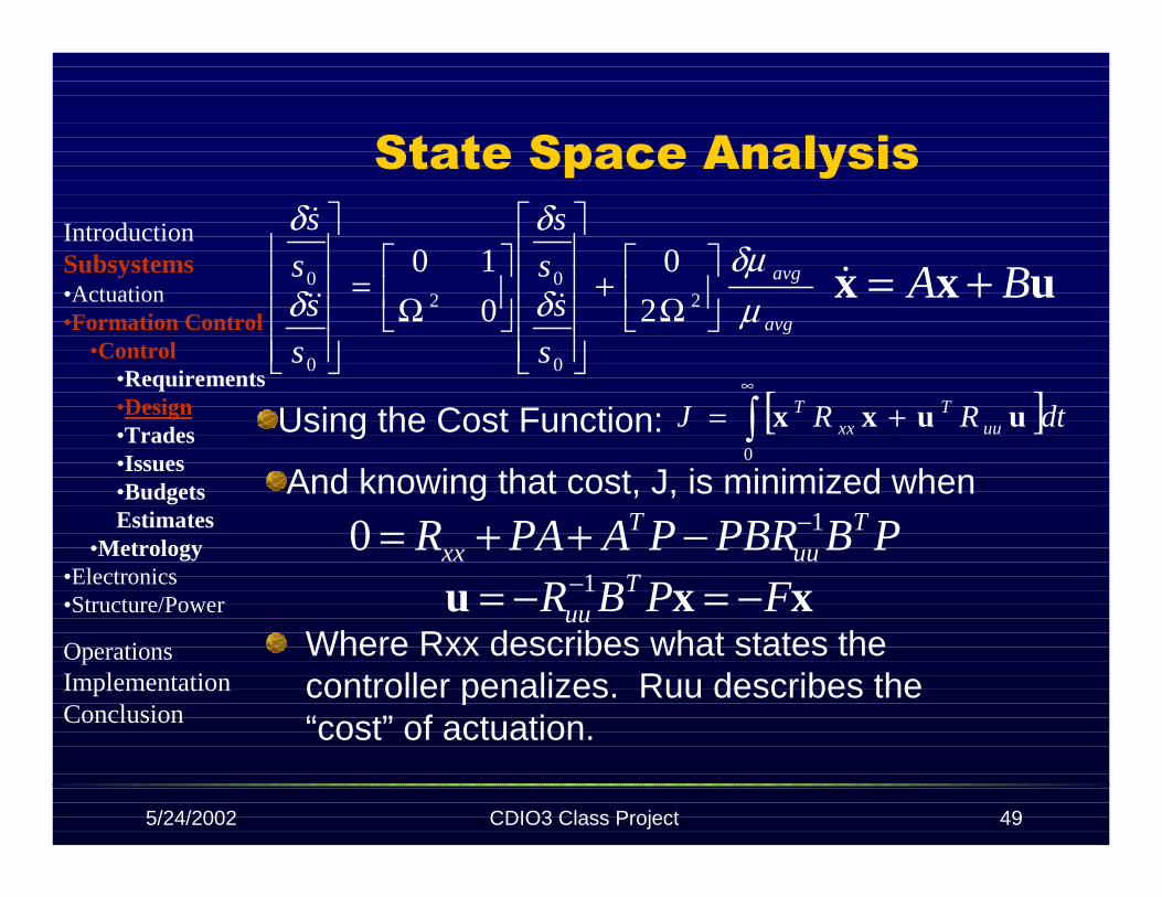
State Space Analysis
Where Rxx describes what states thecontroller penalizes. Ruu describes the“cost” of actuation.
[ ]∫∞
+=0
dtRRJ uuT
xxT uuxx
xxu FPBR Tuu −=−= −1
PBPBRPAPAR Tuu
Txx
10 −−++=
uxx BA +=&
Using the Cost Function:
And knowing that cost, J, is minimized when
avg
avg
s
ss
s
s
ss
s
µδµ
δ
δ
δ
δ
Ω
+
Ω
=
2
0
02
0
0
2
0
0
10&&&
&IntroductionSubsystems•Actuation•Formation Control
•Control•Requirements•Design•Trades•Issues•BudgetsEstimates
•Metrology•Electronics•Structure/Power
OperationsImplementationConclusion
5/24/2002 CDIO3 Class Project 50
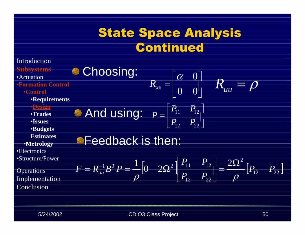
State Space Analysis Continued
Choosing:ρ=uuR
=
00
0αxxR
And using:
=
2212
1211
PP
PPP
Feedback is then:
[ ] [ ]2212
2
2212
121121 220
1PP
PP
PPPBRF T
uu ρρΩ=
Ω== −
IntroductionSubsystems•Actuation•Formation Control
•Control•Requirements•Design•Trades•Issues•BudgetsEstimates
•Metrology•Electronics•Structure/Power
OperationsImplementationConclusion

5/24/2002 CDIO3 Class Project 51
Now solve for the closed loop matrixwhere
Evaluate as increases from 0
State Space Analysis Continued
[ ] xxuxx CLABFABA =−=+=&xu F−=
ρα ∞
Therefore the closedloop poles for the mostefficient controller lie alongthis curve
IntroductionSubsystems•Actuation•Formation Control
•Control•Requirements•Design•Trades•Issues•BudgetsEstimates
•Metrology•Electronics•Structure/Power
OperationsImplementationConclusion
5/24/2002 CDIO3 Class Project 52
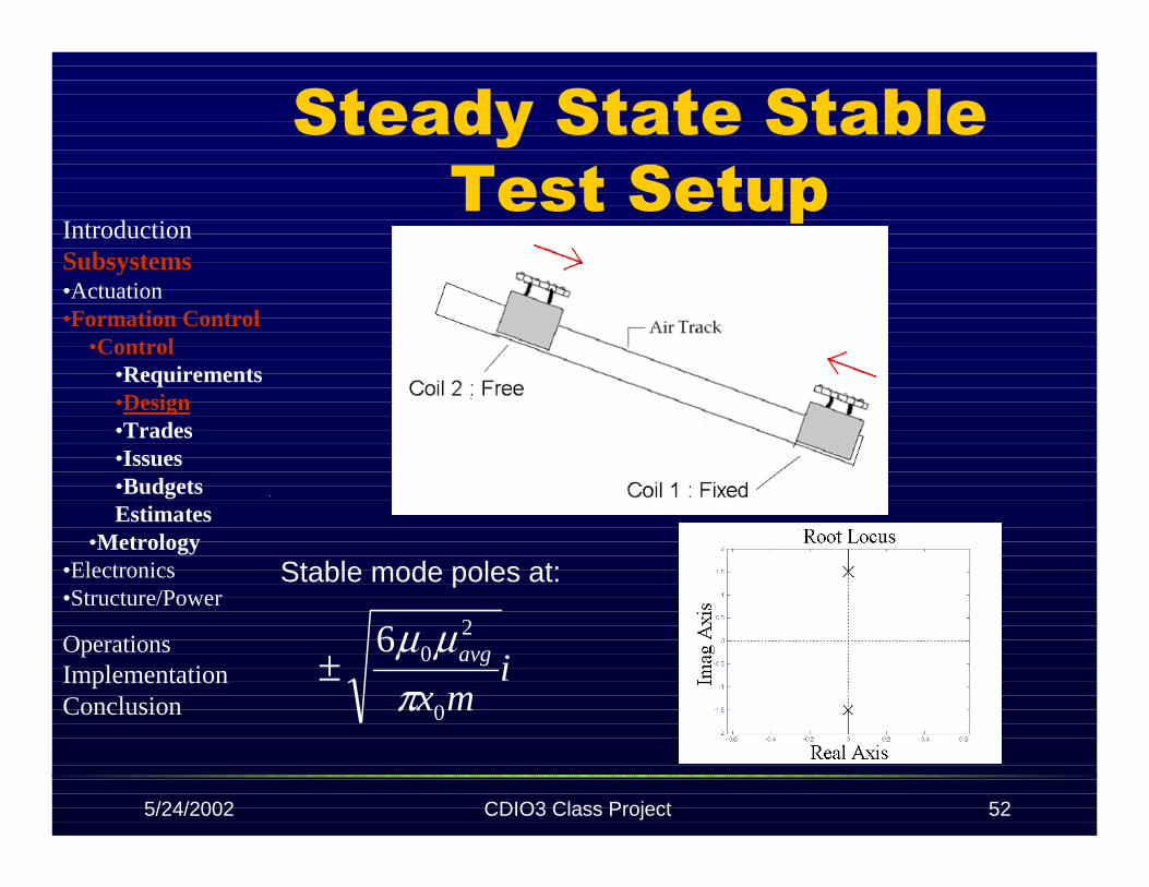
Steady State Stable Test Setup
imx
avg
0
206
πµµ
±
Stable mode poles at:
IntroductionSubsystems•Actuation•Formation Control
•Control•Requirements•Design•Trades•Issues•BudgetsEstimates
•Metrology•Electronics•Structure/Power
OperationsImplementationConclusion
5/24/2002 CDIO3 Class Project 53
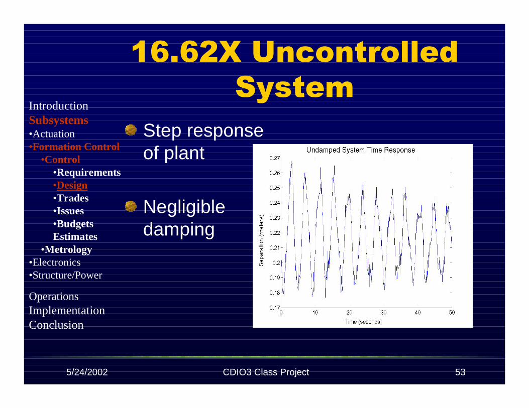
16.62X Uncontrolled System
Step responseof plant
Negligibledamping
IntroductionSubsystems•Actuation•Formation Control
•Control•Requirements•Design•Trades•Issues•BudgetsEstimates
•Metrology•Electronics•Structure/Power
OperationsImplementationConclusion
5/24/2002 CDIO3 Class Project 54
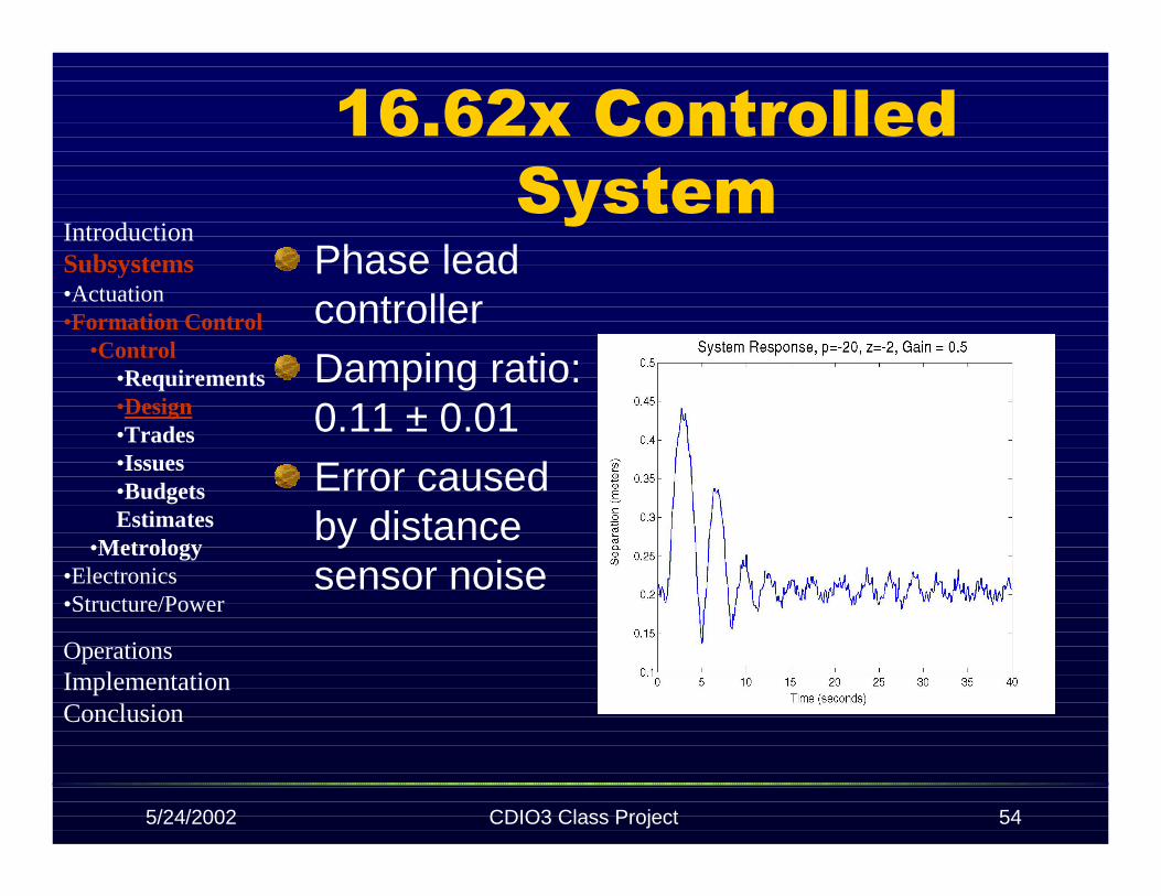
16.62x Controlled System
Phase leadcontrollerDamping ratio:0.11 ± 0.01
Error causedby distancesensor noise
IntroductionSubsystems•Actuation•Formation Control
•Control•Requirements•Design•Trades•Issues•BudgetsEstimates
•Metrology•Electronics•Structure/Power
OperationsImplementationConclusion
5/24/2002 CDIO3 Class Project 55
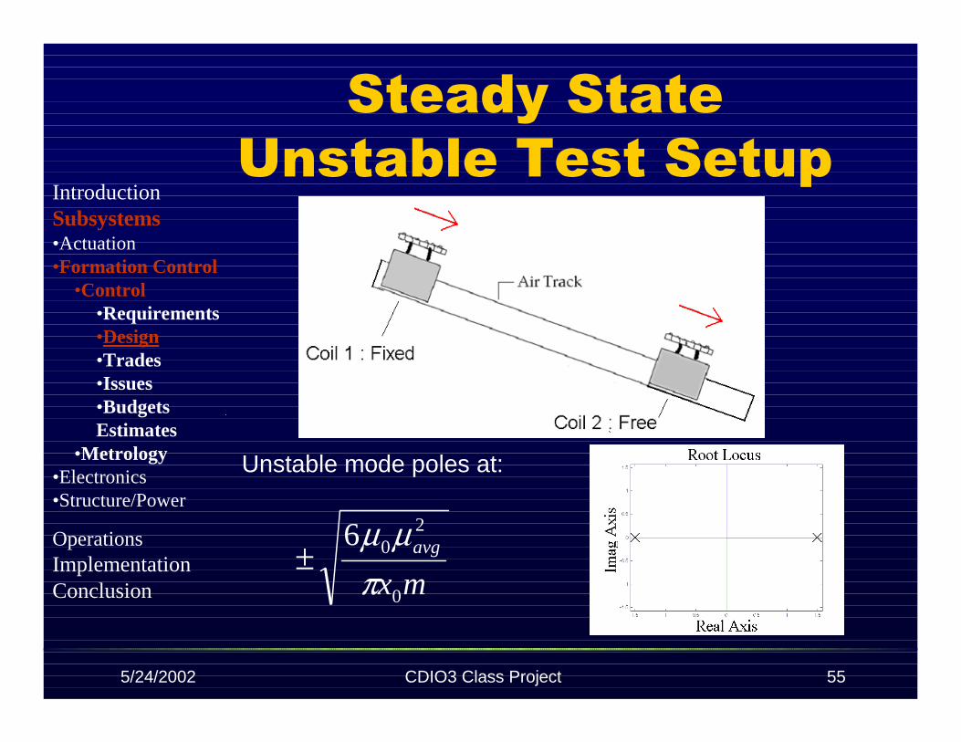
Steady State Unstable Test Setup
mxavg
0
206
πµµ
±
Unstable mode poles at:
IntroductionSubsystems•Actuation•Formation Control
•Control•Requirements•Design•Trades•Issues•BudgetsEstimates
•Metrology•Electronics•Structure/Power
OperationsImplementationConclusion

5/24/2002 CDIO3 Class Project 56
Controller forUnstable Test Setup
Phase Lead Controller
p = -20, z = -3, k = 30
Damping = 0.68
IntroductionSubsystems•Actuation•Formation Control
•Control•Requirements•Design•Trades•Issues•BudgetsEstimates
•Metrology•Electronics•Structure/Power
OperationsImplementationConclusion
5/24/2002 CDIO3 Class Project 57
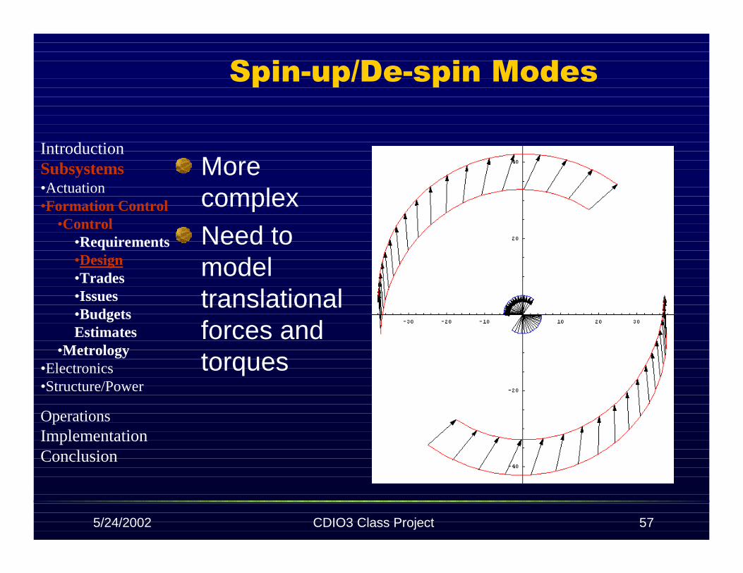
Spin-up/De-spin Modes
MorecomplexNeed tomodeltranslationalforces andtorques
IntroductionSubsystems•Actuation•Formation Control
•Control•Requirements•Design•Trades•Issues•BudgetsEstimates
•Metrology•Electronics•Structure/Power
OperationsImplementationConclusion

5/24/2002 CDIO3 Class Project 58
Initial Spin-up Forces
Results in a force and a torque on eachmagnet
S NS
N
s
IntroductionSubsystems•Actuation•Formation Control
•Control•Requirements•Design•Trades•Issues•BudgetsEstimates
•Metrology•Electronics•Structure/Power
OperationsImplementationConclusion
5/24/2002 CDIO3 Class Project 59
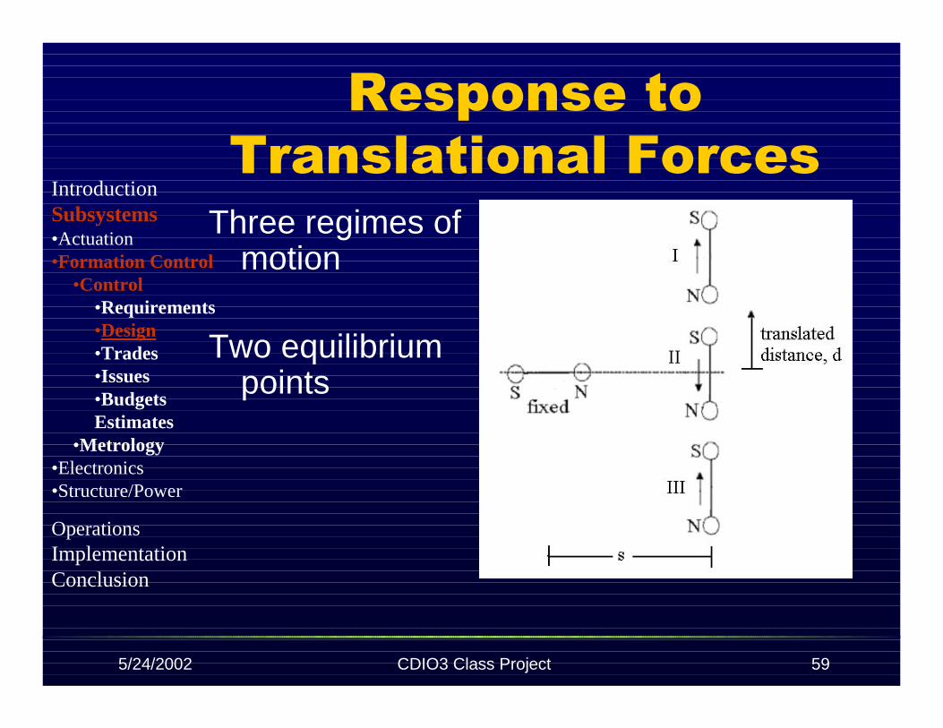
Response to Translational Forces
Three regimes ofmotion
Two equilibriumpoints
IntroductionSubsystems•Actuation•Formation Control
•Control•Requirements•Design•Trades•Issues•BudgetsEstimates
•Metrology•Electronics•Structure/Power
OperationsImplementationConclusion

5/24/2002 CDIO3 Class Project 60
Due to the configuration,when α + β = 0, thus when d = s
Response to Translational Forces
( )[ ]βαπµµ
+= Sins
F avgtrans 4
20
4
3
±0=transF
IntroductionSubsystems•Actuation•Formation Control
•Control•Requirements•Design•Trades•Issues•BudgetsEstimates
•Metrology•Electronics•Structure/Power
OperationsImplementationConclusion
5/24/2002 CDIO3 Class Project 61
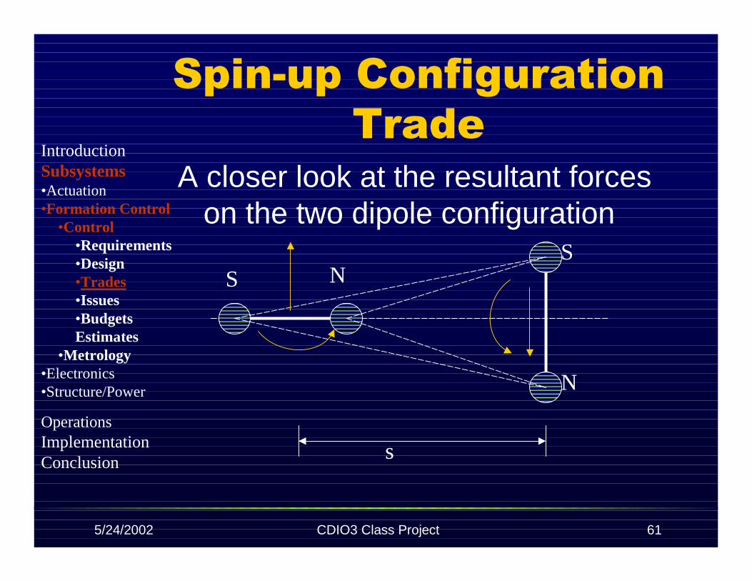
Spin-up Configuration Trade
A closer look at the resultant forceson the two dipole configuration
S NS
N
s
IntroductionSubsystems•Actuation•Formation Control
•Control•Requirements•Design•Trades•Issues•BudgetsEstimates
•Metrology•Electronics•Structure/Power
OperationsImplementationConclusion

5/24/2002 CDIO3 Class Project 62
Spin-up Configuration Trade
α=0, β=90
[ ])(3)(8
20 βαβα
πµµ
τ ++−= SinavgA
[ ])(3)(8
20 αβαβ
πµµ
τ ++−= SinavgB
[ ]
[ ] 2
1
4
2
)(3)(8
)(3)(8
20
20
==++−
++−=
αβαβπµµ
βαβαπµµ
ττ
Sin
Sin
avg
avg
B
A
S NS
NA
B
s
IntroductionSubsystems•Actuation•Formation Control
•Control•Requirements•Design•Trades•Issues•BudgetsEstimates
•Metrology•Electronics•Structure/Power
OperationsImplementationConclusion

5/24/2002 CDIO3 Class Project 63
Spin-up Configuration Trade
Configuration options:
• Favors a largercenter vehicle
• Favors equallysized vehicles
IntroductionSubsystems•Actuation•Formation Control
•Control•Requirements•Design•Trades•Issues•BudgetsEstimates
•Metrology•Electronics•Structure/Power
OperationsImplementationConclusion

5/24/2002 CDIO3 Class Project 64
Control Location Trade
CentralizedAll information communicated to a hubwhich calculates a control solution
Independent ControlVehicles collect and process their owninformation and derive a control solutionfor their own vehicle
Hybrid controlCertain systems are controlledindependently while other systems arecontrolled by the hub’s control solution
IntroductionSubsystems•Actuation•Formation Control
•Control•Requirements•Design•Trades•Issues•BudgetsEstimates
•Metrology•Electronics•Structure/Power
OperationsImplementationConclusion

5/24/2002 CDIO3 Class Project 65
Hysteresis and Saturation
HysteresisExperimental data
for curve
Saturation of electromagnets andtorque wheels
IntroductionSubsystems•Actuation•Formation Control
•Control•Requirements•Design•Trades•Issues•BudgetsEstimates
•Metrology•Electronics•Structure/Power
OperationsImplementationConclusion

5/24/2002 CDIO3 Class Project 66
Budget Estimates
No massNo powerCost for maintenance of labequipment
IntroductionSubsystems•Actuation•Formation Control
•Control•Requirements•Design•Trades•Issues•BudgetsEstimates
•Metrology•Electronics•Structure/Power
OperationsImplementationConclusion

5/24/2002 CDIO3 Class Project 67
Metrology
Metrology
Oscar Murillo
IntroductionSubsystems•Actuation•Formation Control
•Control•Metrology
•Requirements•Trades•Design•Issues•BudgetEstimates
•Electronics•Structure/Power
OperationsImplementationConclusion