Embed Size (px)
Citation preview
Copyright 2015 Milone & MacBroom, Inc.
PRELIMINARY DESIGN REPORT
STATE PIER COMPLEX IMPROVEMENTS
NEW LONDON, CONNECTICUT
State Project No. 94-222/247
MMI #1433-79-6
September 2014
(Revised April 2015)
Prepared for:
State of Connecticut
Department of Transportation
2800 Berlin Turnpike
Newington, Connecticut 06131-7546
Prepared by:
MILONE & MACBROOM, INC.
99 Realty Drive
Cheshire, Connecticut 06410
(203) 271-1773
www.miloneandmacbroom.com
In association with:
HDR, Inc., Mueser Rutledge Consulting Engineers,
Hydro Data, Inc., and Marpro Associates, International
PRELIMINARY DESIGN REPORT
STATE PIER COMPLEX IMPROVEMENTS
SEPTEMBER 2014 (REVISED APRIL 2015) TC-i
TABLE OF CONTENTS
Page
1.0 Introduction ........................................................................................................................ 1
1.1 Project Overview ............................................................................................................. 1
1.2 Project Scope ................................................................................................................... 2
1.3 Project Team .................................................................................................................... 3
2.0 Existing Facilities and Operations .................................................................................... 3
2.1 Project Location ............................................................................................................... 3
2.2 Site Access and Upland Facilities .................................................................................... 4
2.2.1 Roadways ............................................................................................................. 4
2.2.2 Site ....................................................................................................................... 6
2.2.3 Warehouse Structures .......................................................................................... 6
2.2.4 Transit Structures ................................................................................................. 7
2.2.5 Administration Building ...................................................................................... 8
2.2.6 Bridges ................................................................................................................. 8
2.2.7 Retaining Walls .................................................................................................... 9
2.2.8 Railroad Tracks .................................................................................................... 9
2.3 Wharf Structures and Disposition .................................................................................... 9
2.3.1 Northwest Quay – Stone Bulkhead .................................................................... 10
2.3.2 CVRR Pier (Long Dock) ................................................................................... 10
2.3.3 Central Wharf Platform (Between Two Piers)................................................... 12
2.3.4 Admiral Shear State Pier .................................................................................... 13
2.3.5 Northeast State Pier Timber Section Wharf Platform........................................ 14
2.3.6 Northeast Quay Steel Sheeting Bulkhead .......................................................... 15
2.3.7 Mooring Dolphins .............................................................................................. 16
2.4 Cargo Operations and Operating Equipment ................................................................. 16
2.5 Freight Rail .................................................................................................................... 17
PRELIMINARY DESIGN REPORT
STATE PIER COMPLEX IMPROVEMENTS
SEPTEMBER 2014 (REVISED APRIL 2015) TC-ii
TABLE OF CONTENTS (continued)
Page
3.0 Site Data and Testing ....................................................................................................... 18
3.1 CTDOT-Furnished Data ................................................................................................ 18
3.2 Topographic and Hydrographic Survey ......................................................................... 19
3.3 Utilities ........................................................................................................................... 20
3.3.1 Existing Utilities ................................................................................................ 20
3.3.1.1 Transmission Lines ............................................................................. 20
3.3.1.2 Former City Street Utilities ................................................................. 21
3.3.1.3 Utilities Upland of Pier ....................................................................... 22
3.3.1.4 Utilities Associated with Pier.............................................................. 25
3.4 Stormwater Management ............................................................................................... 26
3.4.1 Existing Conditions ............................................................................................ 26
3.5 Geotechnical Investigation............................................................................................. 26
3.5.1 Admiral Shear State Pier .................................................................................... 27
3.5.2 CVRR Pier (Long Dock) ................................................................................... 28
3.5.3 Center Shoreline and Pile-Supported Wharf Platform Between Piers ............... 28
3.5.4 Northeast Pile-Supported Platform and Quay Sheet Pile Bulkhead .................. 28
3.5.5 Northeast Quay Sheet Pile Bulkhead ................................................................. 28
3.5.6 Northwest Quay Stone Bulkhead ....................................................................... 28
4.0 Functional and Operational Planned Improvements ................................................... 29
4.1 Site Access, Upland Facilities, and Yard Operations .................................................... 29
4.1.1 Site Access ......................................................................................................... 29
4.1.2 Upland Facilities ................................................................................................ 32
4.2 Utilities ........................................................................................................................... 33
4.3 Stormwater Management ............................................................................................... 34
PRELIMINARY DESIGN REPORT
STATE PIER COMPLEX IMPROVEMENTS
SEPTEMBER 2014 (REVISED APRIL 2015) TC-iii
TABLE OF CONTENTS (continued)
Page
4.4 Wharf Structures and Waterfront Cargo Operations ..................................................... 35
4.4.1 Admiral Shear State Pier: Toe-Wall/Bulkhead ................................................. 37
4.4.2 CVRR Pier: Enclosed Bulkhead Structure and Pile-Supported
Marginal Wharf ......................................................................................... 39
4.4.3 Central Wharf Structure: Pile-Supported Marginal Wharf ............................... 39
4.4.4 Northeast Timber Wharf: Sheet Pile Bulkhead Wall ........................................ 40
4.4.5 Northeast Quay Wall Structure: Sheet Pile Bulkhead with Tiebacks and
Deadman ................................................................................................... 40
4.4.6 Northwest Quay Wall - Bulkhead ...................................................................... 41
4.5 Dredging and Dredged Material Management .............................................................. 41
4.5.1 Planned Improvements....................................................................................... 41
4.6 Freight Rail .................................................................................................................... 46
4.6.1 Planned Improvements....................................................................................... 46
4.6.2 Requirements and Constraints ........................................................................... 47
4.7 Site Security ................................................................................................................... 47
5.0 Permits and Approvals .................................................................................................... 50
5.1 Jurisdictional Boundaries and Permits Required ........................................................... 50
5.2 Stakeholder Coordination .............................................................................................. 52
6.0 Design Procedures and Input Parameters ..................................................................... 52
6.1 Project Datum and Horizontal Controls ......................................................................... 52
6.2 Wharf Structures and Waterfront Cargo Operations ..................................................... 53
6.3 Prop Wash and Scour ..................................................................................................... 53
6.4 Design Dredged Depth ................................................................................................... 53
6.5 Soil Parameters .............................................................................................................. 54
6.6 Wharf and Quay Bulkhead Design Methodology .......................................................... 54
6.7 Framed Wharf Structures Design Methodology ............................................................ 56
PRELIMINARY DESIGN REPORT
STATE PIER COMPLEX IMPROVEMENTS
SEPTEMBER 2014 (REVISED APRIL 2015) TC-iv
TABLE OF CONTENTS (continued)
Page
6.8 Freight Rail Design Methodology ................................................................................. 56
7.0 Design Loads and Loading Combinations ..................................................................... 58
7.1 Wharf and Yard Live Loading ....................................................................................... 58
7.1.1 Design Vessel Parameters for Each Structure ................................................... 58
7.1.2 Structural Deck Loads........................................................................................ 59
7.1.3 Storage Areas ..................................................................................................... 60
7.1.4 Designated Roads............................................................................................... 60
7.1.5 Freight Rail ........................................................................................................ 60
7.1.6 Mooring and Breasting Loads ............................................................................ 61
7.1.7 Environmental Loads (delta T, wind, ice, current) ............................................ 62
7.1.8 Load Combinations ............................................................................................ 63
8.0 Project Phasing................................................................................................................. 64
9.0 Estimated Construction Costs ........................................................................................ 66
APPENDICES
APPENDIX A – Topographic and Hydrographic Survey
APPENDIX B – Geotechnical Information
APPENDIX C – Pier Inspection Report
APPENDIX D – American Marine Highway Design Report
APPENDIX E – Key Stakeholder Meeting Minutes and Correspondence
APPENDIX F – Cost Estimates
PRELIMINARY DESIGN REPORT
STATE PIER COMPLEX IMPROVEMENTS
SEPTEMBER 2014 (REVISED APRIL 2015) PAGE 1
1.0 INTRODUCTION
1.1 Project Overview
The Connecticut General Assembly funded construction of State Pier almost 100 years ago to
facilitate business and commerce in the state. The mission of the facility today remains
essentially the same as at inception. With the addition of the Central Vermont Railroad (CVRR)
Pier in 2001, the State Pier facility contains approximately 4,000 linear feet of dockage along its
two main piers, on-dock rail connectivity to the New England Central Railroad (now owned by
Genesee & Wyoming) system, 200,000 square feet of warehouse space, deep water access, and
direct connection to the interstate highway system. The site is generally known as the State Pier
Complex, which not only includes waterfront features such as piers and quay walls but also
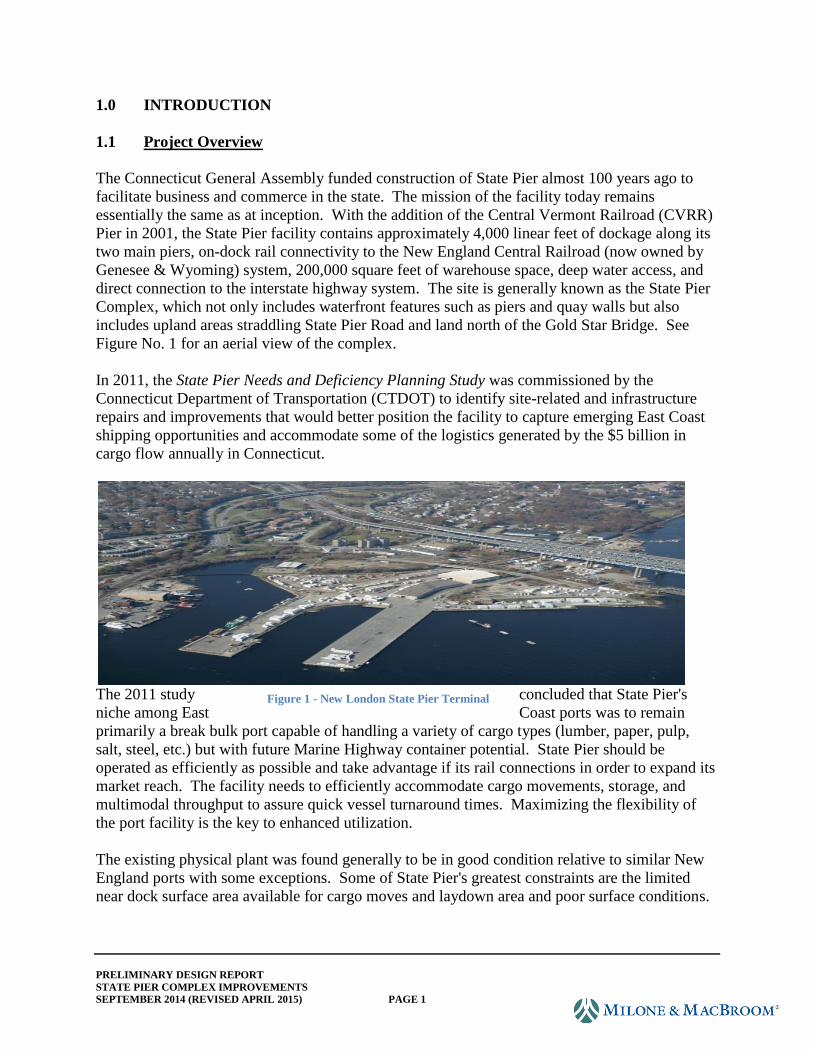
includes upland areas straddling State Pier Road and land north of the Gold Star Bridge. See
Figure No. 1 for an aerial view of the complex.
In 2011, the State Pier Needs and Deficiency Planning Study was commissioned by the
Connecticut Department of Transportation (CTDOT) to identify site-related and infrastructure
repairs and improvements that would better position the facility to capture emerging East Coast
shipping opportunities and accommodate some of the logistics generated by the $5 billion in
cargo flow annually in Connecticut.
The 2011 study concluded that State Pier's
niche among East Coast ports was to remain
primarily a break bulk port capable of handling a variety of cargo types (lumber, paper, pulp,
salt, steel, etc.) but with future Marine Highway container potential. State Pier should be
operated as efficiently as possible and take advantage if its rail connections in order to expand its
market reach. The facility needs to efficiently accommodate cargo movements, storage, and
multimodal throughput to assure quick vessel turnaround times. Maximizing the flexibility of
the port facility is the key to enhanced utilization.
The existing physical plant was found generally to be in good condition relative to similar New
England ports with some exceptions. Some of State Pier's greatest constraints are the limited
near dock surface area available for cargo moves and laydown area and poor surface conditions.
Figure 1 - New London State Pier Terminal
PRELIMINARY DESIGN REPORT
STATE PIER COMPLEX IMPROVEMENTS
SEPTEMBER 2014 (REVISED APRIL 2015) PAGE 2
Dredging to achieve uniform depths for both piers and the poor structural and overall condition
of the CVRR Pier are among the most challenging deficiencies that need to be remedied.
The State Pier Facility Master Plan developed in 2011 calls for the following improvements:
Improved vehicular access and circulation
Restored and enhanced rail connectivity
Dredging and disposal
Enhanced vessel accommodations
Defined storage and laydown areas
Upland grading and surface improvements
Provision for new (future) warehouse building
Provision to accommodate limited containerized cargo
Structural improvements to piers, bulkheads, and quay walls
Stormwater controls, treatment measures
Enhanced security, separation of noncompatible uses
Equipment upgrades, procurement
Vegetation management
Refined port management and marketing plan
1.2 Project Scope
CTDOT has elected to proceed with preliminary design of improvements generally as outlined in
the State Pier Needs and Deficiencies Study. The current design phase includes due diligence,
development and evaluation of alternatives, and preliminary engineering followed by
preliminary design. Due diligence includes:
Site visits
Subsurface soils investigations, both upland and in-water
Structure inspections, including underwater
Topographic survey (by CTDOT)
Hydrographic survey
Utility mapping
Review of available environmental data for dredge materials
Identification and mapping of regulatory limits
Assessment of alternatives involved structure rehabilitation options along with various upland
grading schemes and site layout scenarios. Preliminary Design plans generally depict:
Site layout and circulation
Location of buildings, drives, parking, etc.
Access road design
Site security provisions
PRELIMINARY DESIGN REPORT
STATE PIER COMPLEX IMPROVEMENTS
SEPTEMBER 2014 (REVISED APRIL 2015) PAGE 3
Site grading, retaining walls, and drainage
Structure rehabilitation plans and details
Dredge plans
Schematic utility and illumination layout
Track restoration layout and details
The Preliminary Design submission represents deliverables essentially considered 35%
complete, which shall be submitted and reviewed by CTDOT. The goal of the 35% design is to
further develop the project in an effort to better understand opportunities, impacts, and costs.
This report is intended to address environmental, utility, right-of-way, and other constraints and
needs. The Preliminary Design submission also includes an engineer's opinion of probable
construction costs and will serve to further discussions with CTDOT relative to phasing the
work.
1.3 Project Team
The prime consultant for this assignment is Milone & MacBroom, Inc. assisted by the following
subconsultants and subcontractors:
HDR, Inc.: Marine consultation/design; rail design
Mueser Rutledge: Geotechnical engineering; coordination and inspection of land and
in-water borings
Marpro Associates, International: Port operations; sequencing work (a part of
original study team)
A. DiCesare Associates: Underwater inspections (SBE)
Hydro Data, Inc.: Hydrographic Survey (SBE)
New England Boring Contractors: Driller
2.0 EXISTING FACILITIES AND OPERATIONS
2.1 Project Location (Refer to title sheet and existing conditions plans.)
The State Pier facility is situated in the city of New London, Connecticut on the Thames River
approximately two miles from the eastern end of Long Island Sound and eight miles from the
open Atlantic shipping lanes. State Pier is accessed by vessels transiting a 40-foot-deep, 500-
foot-wide navigation channel maintained by the United States Army Corps of Engineers
(USACE). Refer to the illustration entitled "Property Ownership and Easements" for a depiction
of the overall project area under state ownership.
PRELIMINARY DESIGN REPORT
STATE PIER COMPLEX IMPROVEMENTS
SEPTEMBER 2014 (REVISED APRIL 2015) PAGE 4
2.2 Site Access and Upland Facilities
2.2.1 Roadways
Vehicular access to the State Pier facility is direct from Interstate 95, State Route 32, and
Interstate 395 via a limited access interchange to State Pier Road. The roadway geometry on
Williams Street, State Pier Road, and Crystal Avenue is adequate for typical tractor trailer use.
Vehicular access to the State Pier facility is considered desirable. From I-95, vehicles depart the
expressway at Exits 83 and 84 for northbound and southbound vehicles respectively and access
State Pier Road (SSR 437) via Williams Street. Access is also available from CT Route 32 to
Crystal Avenue and a right turn onto State Pier Road.
Once near the site, vehicles are required to make a 90° right turn onto the port access driveway.
The driveway is 28 feet wide curb to curb and carries one lane of traffic in each direction.
Vertically, the driveway grade descends from the State Pier Road intersection at a 3.6% grade.
At the bottom of the driveway, vehicles are required to stop and check in with port security.
Under some conditions, vehicles queue on the driveway as drivers await check in, which does
cause moderate delays, reducing the efficiency of port operations to some degree.
The facility is accessible via Thomas Griffin Road from the west, a city-owned roadway. While
Thomas Griffin Road provides direct physical access to the lower portion of the site in the
vicinity of CVRR Pier, the connection is fenced or gated and is not utilized with any regularity.
The previous State Pier Needs & Deficiencies Study identifies this roadway as a vital link for
enhancing port operations and connectivity to the local roadway network. While Thomas Griffin
Road may not become a main point of entry (assuming State Pier remains the primary and
secured access way), the local roadway does provide a meaningful and effective opportunity for
emergency or special access. Based on available mapping, the roadway would appear to
terminate on private property that abuts the state-owned property, and it is unclear whether the
state maintains an easement or right of passage. CTDOT conducted a boundary survey for the
property and, based on the mapping furnished, no easement was identified. As the final design
progresses, it may be necessary to broaden the right-of-way investigation in this area to
determine whether legal access exists. In either case, the CTDOT may want to consider
formalizing this point of entry, even if a right-of-way activity becomes inevitable.
PRELIMINARY DESIGN REPORT
STATE PIER COMPLEX IMPROVEMENTS
SEPTEMBER 2014 (REVISED APRIL 2015) PAGE 5
PRELIMINARY DESIGN REPORT
STATE PIER COMPLEX IMPROVEMENTS
SEPTEMBER 2014 (REVISED APRIL 2015) PAGE 6
2.2.2 Site
The State Pier facility encompasses nearly 30 acres and has three general operational areas: the
piers, near dock shoreline areas, and upland storage areas. The upland storage areas comprise
about one-fourth of the overall acreage and are situated north of and separated from the main
port facility by State Pier Road and Amtrak's rail corridor embankment. The property generally
consists of unpaved, gravel surfaces that are uneven or contain small depressions that pond water
during storm events. The upland areas are segmented by the rail siding to State Pier and bisected
by the bridge piers for I-95's Gold Star Memorial Bridge. The property is bounded to the west
by the New England Central Railroad (NECR) tracks and to the east by the Thames River.
Access from the main port facility to the upland area is provided by three underpasses under
State Pier Road and the Amtrak right-of-way. Security fencing divides the uplands into separate
laydown areas. Currently, a state-owned recreational boat launch facility occupies a portion of
the eastern shoreline and is not used for port operations.
The near-dock shoreline areas are south of State Pier Road and accommodate most of the port's
cargo intermodal activity. This area contains two heavy load warehouse buildings totaling
102,000 square feet with railcar and truck loading docks, two 3,200-square-foot equipment
storage/maintenance buildings, an administration building, and several small modular buildings
that house port security and operations personnel. The area located at the head of the two piers is
largely paved to facilitate forklift truck and tractor truck movements. The shore edge consists of
a combination of sheet piling, pile-supported docks, and stone block quay walls. The knoll area
and western area adjoining the NECR siding yard are largely unpaved areas, and the topography
is somewhat irregular. This area of these two locations is approximately 8.3 acres.
In total, the facility incorporates six primary structures consisting of two warehouses, a
maintenance garage, two storage buildings, and an administration office building.
2.2.3 Warehouse Structures
Warehouse space on site consists of approximately 102,000 square feet located in two primary
structures:
Warehouse Number 1 was constructed in 1967 and is
460' x 120' for a gross area of approximately 55,000
square feet. The building has rail access with four
loading docks along the east side and truck access with
loading docks along the west side and access ramps at
the north and south ends of the building.
Warehouse Number 2 was built in 1990 and is 220' x
215' for a gross area of approximately 47,000 square
feet. The building has rail access with two loading
docks along the east side and four truck loading docks
and an access with a ramp into the building at the south side and at the northeast end
Figure 2 - Warehouse Number 1
PRELIMINARY DESIGN REPORT
STATE PIER COMPLEX IMPROVEMENTS
SEPTEMBER 2014 (REVISED APRIL 2015) PAGE 7
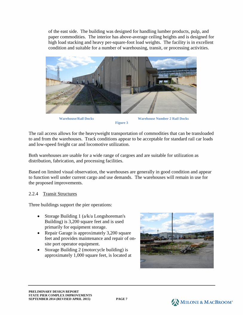
of the east side. The building was designed for handling lumber products, pulp, and
paper commodities. The interior has above-average ceiling heights and is designed for
high load stacking and heavy per-square-foot load weights. The facility is in excellent
condition and suitable for a number of warehousing, transit, or processing activities.
Warehouse/Rail Docks Warehouse Number 2 Rail Docks
Figure 3
The rail access allows for the heavyweight transportation of commodities that can be transloaded
to and from the warehouses. Track conditions appear to be acceptable for standard rail car loads
and low-speed freight car and locomotive utilization.
Both warehouses are usable for a wide range of cargoes and are suitable for utilization as
distribution, fabrication, and processing facilities.
Based on limited visual observation, the warehouses are generally in good condition and appear
to function well under current cargo and use demands. The warehouses will remain in use for
the proposed improvements.
2.2.4 Transit Structures
Three buildings support the pier operations:
Storage Building 1 (a/k/a Longshoreman's
Building) is 3,200 square feet and is used
primarily for equipment storage.
Repair Garage is approximately 3,200 square
feet and provides maintenance and repair of on-
site port operator equipment.
Storage Building 2 (motorcycle building) is
approximately 1,000 square feet, is located at
PRELIMINARY DESIGN REPORT
STATE PIER COMPLEX IMPROVEMENTS
SEPTEMBER 2014 (REVISED APRIL 2015) PAGE 8
the far northern end of the northeast quay wall, and is abandoned.
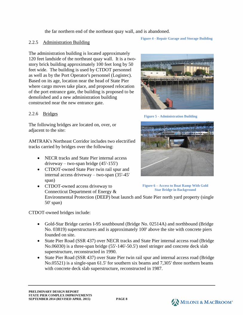
2.2.5 Administration Building
The administration building is located approximately
120 feet landside of the northeast quay wall. It is a two-
story brick building approximately 100 feet long by 50
feet wide. The building is used by CTDOT personnel
as well as by the Port Operator's personnel (Logistec).
Based on its age, location near the head of State Pier
where cargo moves take place, and proposed relocation
of the port entrance gate, the building is proposed to be
demolished and a new administration building
constructed near the new entrance gate.
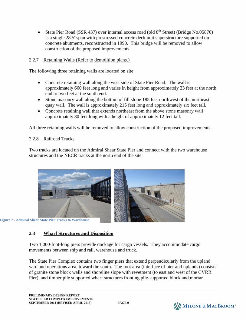
2.2.6 Bridges
The following bridges are located on, over, or
adjacent to the site:
AMTRAK's Northeast Corridor includes two electrified
tracks carried by bridges over the following:
NECR tracks and State Pier internal access
driveway – two-span bridge (45'-155')
CTDOT-owned State Pier twin rail spur and
internal access driveway – two-span (35'-45'
span)
CTDOT-owned access driveway to
Connecticut Department of Energy &
Environmental Protection (DEEP) boat launch and State Pier north yard property (single
50' span)
CTDOT-owned bridges include:
Gold-Star Bridge carries I-95 southbound (Bridge No. 02514A) and northbound (Bridge
No. 03819) superstructures and is approximately 100' above the site with concrete piers
founded on site.
State Pier Road (SSR 437) over NECR tracks and State Pier internal access road (Bridge
No.06030) is a three-span bridge (55'-146'-50.5') steel stringer and concrete deck slab
superstructure, reconstructed in 1990.
State Pier Road (SSR 437) over State Pier twin rail spur and internal access road (Bridge
No.05521) is a single-span 61.5' for southern six beams and 7,305' three northern beams
with concrete deck slab superstructure, reconstructed in 1987.
Figure 5 - Administration Building
Figure 4 - Repair Garage and Storage Building
Figure 6 – Access to Boat Ramp With Gold
Star Bridge in Background
PRELIMINARY DESIGN REPORT
STATE PIER COMPLEX IMPROVEMENTS
SEPTEMBER 2014 (REVISED APRIL 2015) PAGE 9
State Pier Road (SSR 437) over internal access road (old 8th Street) (Bridge No.05876)
is a single 28.5' span with prestressed concrete deck unit superstructure supported on
concrete abutments, reconstructed in 1990. This bridge will be removed to allow
construction of the proposed improvements.
2.2.7 Retaining Walls (Refer to demolition plans.)
The following three retaining walls are located on site:
Concrete retaining wall along the west side of State Pier Road. The wall is
approximately 660 feet long and varies in height from approximately 23 feet at the north
end to two feet at the south end.
Stone masonry wall along the bottom of fill slope 185 feet northwest of the northeast
quay wall. The wall is approximately 215 feet long and approximately six feet tall.
Concrete retaining wall that extends northeast from the above stone masonry wall
approximately 80 feet long with a height of approximately 12 feet tall.
All three retaining walls will be removed to allow construction of the proposed improvements.
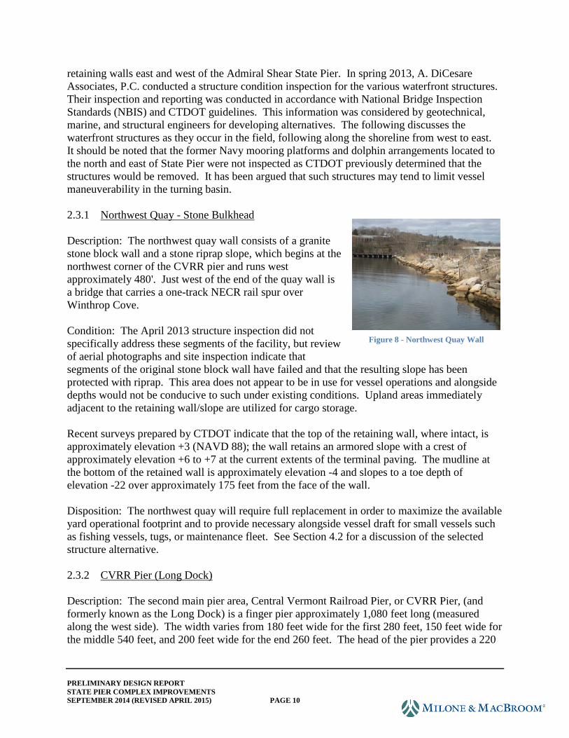
2.2.8 Railroad Tracks
Two tracks are located on the Admiral Shear State Pier and connect with the two warehouse
structures and the NECR tracks at the north end of the site.
2.3 Wharf Structures and Disposition
Two 1,000-foot-long piers provide dockage for cargo vessels. They accommodate cargo
movements between ship and rail, warehouse and truck.
The State Pier Complex contains two finger piers that extend perpendicularly from the upland
yard and operations area, toward the south. The foot area (interface of pier and uplands) consists
of granite stone block walls and shoreline slope with revetment (to east and west of the CVRR
Pier), and timber pile supported wharf structures fronting pile-supported block and mortar
Figure 7 - Admiral Shear State Pier Tracks to Warehouse
PRELIMINARY DESIGN REPORT
STATE PIER COMPLEX IMPROVEMENTS
SEPTEMBER 2014 (REVISED APRIL 2015) PAGE 10
retaining walls east and west of the Admiral Shear State Pier. In spring 2013, A. DiCesare
Associates, P.C. conducted a structure condition inspection for the various waterfront structures.
Their inspection and reporting was conducted in accordance with National Bridge Inspection
Standards (NBIS) and CTDOT guidelines. This information was considered by geotechnical,
marine, and structural engineers for developing alternatives. The following discusses the
waterfront structures as they occur in the field, following along the shoreline from west to east.
It should be noted that the former Navy mooring platforms and dolphin arrangements located to
the north and east of State Pier were not inspected as CTDOT previously determined that the
structures would be removed. It has been argued that such structures may tend to limit vessel
maneuverability in the turning basin.
2.3.1 Northwest Quay - Stone Bulkhead
Description: The northwest quay wall consists of a granite
stone block wall and a stone riprap slope, which begins at the
northwest corner of the CVRR pier and runs west
approximately 480'. Just west of the end of the quay wall is
a bridge that carries a one-track NECR rail spur over
Winthrop Cove.
Condition: The April 2013 structure inspection did not
specifically address these segments of the facility, but review
of aerial photographs and site inspection indicate that
segments of the original stone block wall have failed and that the resulting slope has been
protected with riprap. This area does not appear to be in use for vessel operations and alongside
depths would not be conducive to such under existing conditions. Upland areas immediately
adjacent to the retaining wall/slope are utilized for cargo storage.
Recent surveys prepared by CTDOT indicate that the top of the retaining wall, where intact, is
approximately elevation +3 (NAVD 88); the wall retains an armored slope with a crest of
approximately elevation +6 to +7 at the current extents of the terminal paving. The mudline at
the bottom of the retained wall is approximately elevation -4 and slopes to a toe depth of
elevation -22 over approximately 175 feet from the face of the wall.
Disposition: The northwest quay will require full replacement in order to maximize the available
yard operational footprint and to provide necessary alongside vessel draft for small vessels such
as fishing vessels, tugs, or maintenance fleet. See Section 4.2 for a discussion of the selected
structure alternative.
2.3.2 CVRR Pier (Long Dock)
Description: The second main pier area, Central Vermont Railroad Pier, or CVRR Pier, (and
formerly known as the Long Dock) is a finger pier approximately 1,080 feet long (measured
along the west side). The width varies from 180 feet wide for the first 280 feet, 150 feet wide for
the middle 540 feet, and 200 feet wide for the end 260 feet. The head of the pier provides a 220
Figure 8 - Northwest Quay Wall
PRELIMINARY DESIGN REPORT
STATE PIER COMPLEX IMPROVEMENTS
SEPTEMBER 2014 (REVISED APRIL 2015) PAGE 11
foot (along south face) by 275 foot (along east face) working area. A large portion of the pier
structure is original with inconsistent berthing interfaces.
The pier consists of granite block retaining walls and
structural fill interior, with an interior finished surface
elevation that varies from approximately elevation +4.5 to
+5.5 NAVD 88. The western side of the pier primarily
serves as a mooring location for local fishing fleet with
barge operations taking place at the pier head.
Condition: The western portion of the pier was rehabilitated
in 2004 and is in "fair" condition, per the findings of the
April 2013 inspection. The eastern block wall has failed in
locations and, except at the pier head, does not appear to be
suitable for vessel operations in its current condition. It has been cordoned off with concrete
barriers. The pier is used for cargo storage and stacking operations and for limited barge
loading/offloading operations.
In February 2014, a large cargo vessel was in the process of docking on the east side of State Pier
with the assistance of a tugboat. During the docking operation, backwash from the tug's props
caused scour along the base of the western stone masonry wall of the CVRR pier, which caused a
150-foot-long section of the wall to collapse into the water. Emergency repairs are currently
under construction. This incident speaks to the condition of the pier and the relative stability of
the substructure. The proposed improvements will provide for a bulkhead system extending
much deeper into the river bottom. The Preliminary Design plans consider the recent
construction as existing conditions, and the proposed design appropriately incorporates this
work. In addition, our recent involvement in the emergency design and repair operation has
afforded us valuable insight with regard to the type of physical obstructions below the mudline,
as may relate to design considerations for constructability.
Due to settlement and structural deterioration, the finished elevation along the remaining
retaining wall varies but generally falls between elevation +4.5 and +5.5. Maximum existing
available draft is provided off the western and eastern sides of the pier head, where a mudline of
approximate elevation -12 provides about 10.2 feet of available water column for vessel draft
and underclearance at Mean Lower Low Water (MLLW) (defined as elevation -1.65 NAVD 88).
Accordingly, the maximum retained height of the granite block retaining wall is approximately
17.5 feet along this segment of the structure. The southern face of the pier head provides
approximately 6.4 feet of available draft at MLLW, with a structure retained height of
approximately 13.5 feet. The southernmost 120 feet of the eastern pier head provides similar
available draft as the eastern portion (about 10.4 feet), with similar retained height. The
remainder of the pier head is obstructed from direct access by a steel sheet pile wall presumably
placed to mitigate slope failures due to the failing granite block wall in these areas. Breasting
structures outboard of the sheet pile wall have afforded limited barge and similar vessel
operations to remain in service at this location.
Figure 9 - CVRR Pier
PRELIMINARY DESIGN REPORT
STATE PIER COMPLEX IMPROVEMENTS
SEPTEMBER 2014 (REVISED APRIL 2015) PAGE 12
From the toe of the retaining wall, the mudline slopes into the port basin at varying rates, as is
indicated in the hydrographic surveys. Along the pier head, the western toe of the slope is about
elevation -21, occurring approximately 70 feet from the face of the structure. At the south face,
the surface slopes from elevation -8 to -22 over a distance of 140 feet. Along the eastern portion
of the pier, the slope is much steeper, reaching -28 feet over a distance of 50 feet from the
structure face.
Disposition: The CVRR Pier requires substantial improvement in order to provide deep draft
vessel access along the eastern berth line (to be deepened to elevation -38.75) and to provide
intermediate draft vessel access along the western berth line (to be deepened to elevation -23.75).
Emergency repairs to CVRR Pier are currently in progress, which will stabilize 540 feet of the
eastern side of the pier. The repairs consist of steel sheeting bulkhead with tiebacks to a row of
anchor sheet pilling. The repairs have been designed to be incorporated into the final structural
improvements.
The surface of the pier will also be raised approximately 2.5 to 3.5 feet to achieve El. 8.0
NAVD88 at the center of the pier to improve the rail geometry, reduce the potential for
inundation under normal storm conditions, and to provide additional freeboard to improve vessel
working conditions for deeper draft vessels over a larger tidal range. The geotechnical
investigation performed as part of the current project has identified compressible soil lenses
within the structure footprint, which need to be considered in the development of alternatives for
improvement.
The preliminary engineering phase recommended that one set of NECR tracks be extended to the
end of the pier and located at the center of the pier. Updated geotechnical data shows a thick
layer of organic material under a portion of the pier that is projected to cause large settlements
over time. A pile-supported track is recommended to insure a stable track base.
The proposed dredge depth is elevation -37 NAVD along the east face and elevation -22 NAVD
along the west face and south end. See Section 4.2 for discussion of structure alternatives.
2.3.3 Central Wharf Platform (Between Two Piers)
Description: The center shoreline section extends from the eastern edge of the stone block
portion of CVRR Pier to the western edge of State Pier. Beginning at CVRR pier, there is a 300-
foot-long exposed shoreline protected with large stone riprap and concrete slabs up to the top of
the bank. To the east of that is a 115-foot-long by 50-foot-wide timber pile supported wharf
platform that projects over the water from the shoreline. The east edge abuts but is not
physically connected to State Pier. The top of the wharf also matches the top of the State Pier.
PRELIMINARY DESIGN REPORT
STATE PIER COMPLEX IMPROVEMENTS
SEPTEMBER 2014 (REVISED APRIL 2015) PAGE 13
In general, the armored slope head is at approximate
elevation +6 NAVD 88 at the existing jersey barriers
positioned along the south perimeter of the paved site.
Fifteen to 20 feet from the jersey barriers, the armored
portion of the slope begins and drops from elevation +5.5 to
-28 over a distance of 90 feet.
The mudline alongside the northwest timber annex
structure varies from approximately elevation -13 to -21
and slopes to a toe elevation of -32 approximately 40 feet
from the face of this structure.
Condition: The timber section wharf platform (referred to as Northwest Annex in the 2013
inspection report) is in critical condition, has been barricaded, and is not currently used for vessel
or cargo operations. In July 2014, the center shoreline timber wharf failed under the weight of
the precast concrete barrier.
Disposition: The timber pile-supported wharf platform will be demolished, and a new steel pipe
pile-supported structure will be installed along the full segment from the edge of State Pier to the
edge of CVRR Pier. The resulting berth line will be dredged to elevation -38.75 in order to
maximize the length of the alongside deep draft vessel berths for both the CVRR and the State
Piers. No vessels will be moored at this location though the structure should provide for landside
cargo and material storage operations.
2.3.4 Admiral Shear State Pier
Description: The Admiral Shear State Pier is a finger pier approximately 1,000 feet long and
200 feet wide and currently provides the only available berthing area for large cargo ships. The
pier was originally built in 1912, with recent improvements along the east side of the pier
undertaken in 1996-1997 and along the west side in 2001-2002. The improvements included
partial removal of timber piles, installation of steel pipe piles, concrete decking replacement, and
a new fender system. The pier structure consists of 52-foot-wide steel-pipe pile-supported
concrete decking along each side of the pier with a 95-foot-wide central pier structure consisting
of soil-supported precast concrete retaining walls backfilled with structural fill material. The
entire top surface of the pier is comprised of a concrete slab with a concrete paver wearing
surface, except at the two rail lines where the adjacent
surface is bituminous concrete.
Vessels are held off the east and west faces of the pier by
virtue of rubber fender units, each consisting of two unit
element rubber fenders, 2.72 feet long, faced by eight-inch
fender panels with ultra-high-molecular-weight (UHMW)
polyethylene facing. Fenders are bolted to a six-inch blister
in the wharf face, are spaced at 34'-3" typical spacing, and
Figure 10 - Wharf Platform between Piers
Figure 11 - Admiral Shear State Pier
PRELIMINARY DESIGN REPORT
STATE PIER COMPLEX IMPROVEMENTS
SEPTEMBER 2014 (REVISED APRIL 2015) PAGE 14
were installed with shear chains. The south face of the pier head has a timber paneling fendering
system, consisting of vertical timber piles and framing, backed by structural steel walers (W16)
and rubber unit element fender units. One-hundred-ton, single-bitt bollards along the east and
west of the pier are located coincident with fenders, at 68'-6" spacing. The south face provides
four bollards.
The finished elevation of the pier at the center is approximately elevation +9.0. The typical
finished grade at the interior retaining structure was designed to be elevation +8.5 NAVD88 and
slope to +8.0 at the bottom of the 10-inch curb.
State Pier receives the largest current cargo vessels and has also been used for cruise-related
vessel operations. The pier has been assigned an overall existing condition rating as being
"satisfactory" per the April 2013 inspection report. The armored slope below the 52-foot-wide
pile-supported portions of the pier is steep (approximately 1V:1H), and original timber pile stubs
remain from the demolition of the original structure.
The underwater inspection report and side scan sonar performed for the project indicate potential
debris in areas of the berth, which will need to be removed to accommodate dredging and for
constructability reasons.
Hydrographic surveys conducted under this current assignment indicate the elevation of the
mudline alongside the east and west faces of the pier to be approximately -30 NAVD 88 though
in localized areas elevation -27 was recorded; it is not clear whether this is an artifact of original
construction or an issue of outward migration of armor and/or slope toward the basin. The
mudline drops away along the west face to a maximum depth elevation of -38 NAVD 88 over a
distance of 35 feet. Along the east face, the slope varies due to siltation but in the steepest
regions reaches a toe elevation of -40 NAVD 88 approximately 45 feet from the wharf face. In
general, the eastern face basin depth is limited to bottom elevation -38 NAVD 88 (maximum of
36.2 feet water column available at MLLW). The south face of the pier provides less alongside
depth, with mudline at elevation -25.
Disposition: The Admiral Shear State Pier structure will require improvements prior to dredging
in order to provide the targeted berth deepening and prevent existing slope migration and
potential damage to the existing structure. The pier will be dredged to elevation -43.75 along the
eastern berth and elevation -38.75 along the western berth. Significant differential settlement has
occurred along the interface of the central pier portion and the pile-supported segments. It is not
clear as to whether this is due to the migration of foundation soils or consolidation, but it is
recommended that remedial action be considered as part of the improvement project to allow for
the berth deepening. See Preliminary Engineering Report dated November 8, 2013 for a
discussion of the proposed structure alternative.
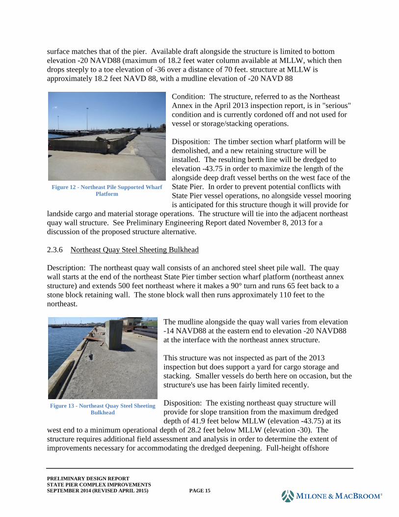
2.3.5 Northeast State Pier Timber Section Wharf Platform
Description: At the foot of and to the east of State Pier is a timber pile supported wharf platform
that is 125 feet long by 50 feet wide. The wharf meets State Pier at a 115° angle, and the top
PRELIMINARY DESIGN REPORT
STATE PIER COMPLEX IMPROVEMENTS
SEPTEMBER 2014 (REVISED APRIL 2015) PAGE 15
surface matches that of the pier. Available draft alongside the structure is limited to bottom
elevation -20 NAVD88 (maximum of 18.2 feet water column available at MLLW, which then
drops steeply to a toe elevation of -36 over a distance of 70 feet. structure at MLLW is
approximately 18.2 feet NAVD 88, with a mudline elevation of -20 NAVD 88
Condition: The structure, referred to as the Northeast
Annex in the April 2013 inspection report, is in "serious"
condition and is currently cordoned off and not used for
vessel or storage/stacking operations.
Disposition: The timber section wharf platform will be
demolished, and a new retaining structure will be
installed. The resulting berth line will be dredged to
elevation -43.75 in order to maximize the length of the
alongside deep draft vessel berths on the west face of the
State Pier. In order to prevent potential conflicts with
State Pier vessel operations, no alongside vessel mooring
is anticipated for this structure though it will provide for
landside cargo and material storage operations. The structure will tie into the adjacent northeast
quay wall structure. See Preliminary Engineering Report dated November 8, 2013 for a
discussion of the proposed structure alternative.
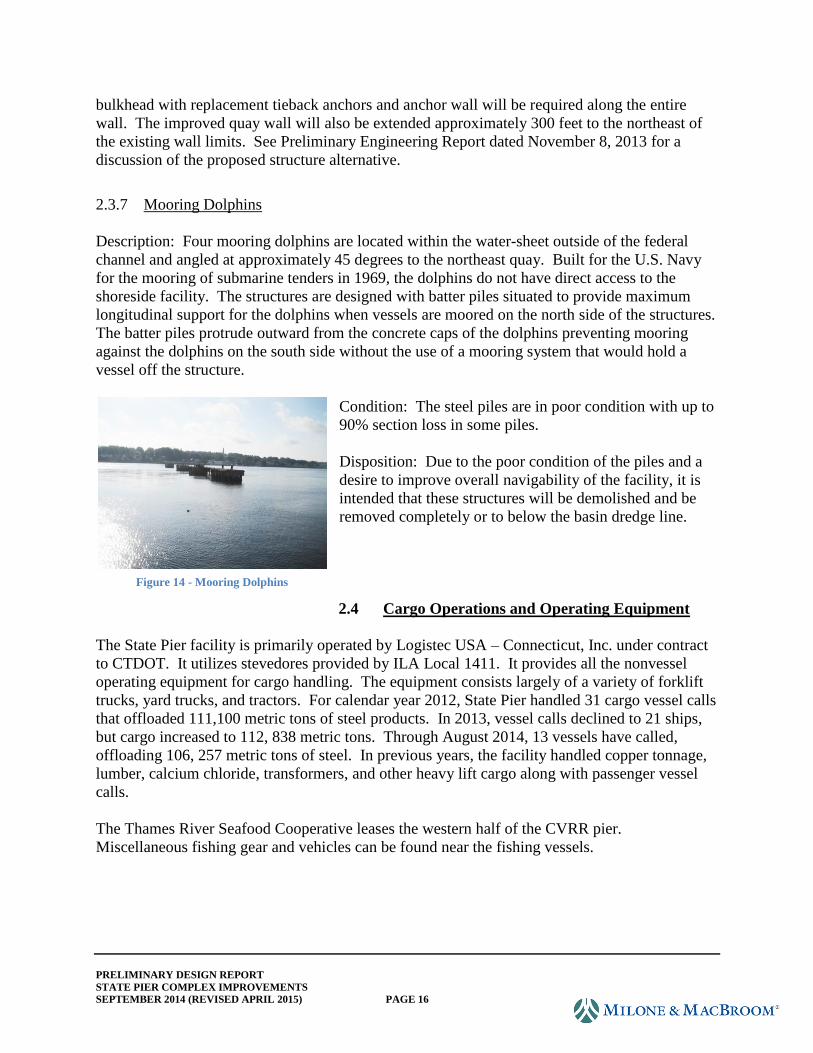
2.3.6 Northeast Quay Steel Sheeting Bulkhead
Description: The northeast quay wall consists of an anchored steel sheet pile wall. The quay
wall starts at the end of the northeast State Pier timber section wharf platform (northeast annex
structure) and extends 500 feet northeast where it makes a 90° turn and runs 65 feet back to a
stone block retaining wall. The stone block wall then runs approximately 110 feet to the
northeast.
The mudline alongside the quay wall varies from elevation
-14 NAVD88 at the eastern end to elevation -20 NAVD88
at the interface with the northeast annex structure.
This structure was not inspected as part of the 2013
inspection but does support a yard for cargo storage and
stacking. Smaller vessels do berth here on occasion, but the
structure's use has been fairly limited recently.
Disposition: The existing northeast quay structure will
provide for slope transition from the maximum dredged
depth of 41.9 feet below MLLW (elevation -43.75) at its
west end to a minimum operational depth of 28.2 feet below MLLW (elevation -30). The
structure requires additional field assessment and analysis in order to determine the extent of
improvements necessary for accommodating the dredged deepening. Full-height offshore
Figure 12 - Northeast Pile Supported Wharf
Platform
Figure 13 - Northeast Quay Steel Sheeting
Bulkhead
PRELIMINARY DESIGN REPORT
STATE PIER COMPLEX IMPROVEMENTS
SEPTEMBER 2014 (REVISED APRIL 2015) PAGE 16
bulkhead with replacement tieback anchors and anchor wall will be required along the entire
wall. The improved quay wall will also be extended approximately 300 feet to the northeast of
the existing wall limits. See Preliminary Engineering Report dated November 8, 2013 for a
discussion of the proposed structure alternative.
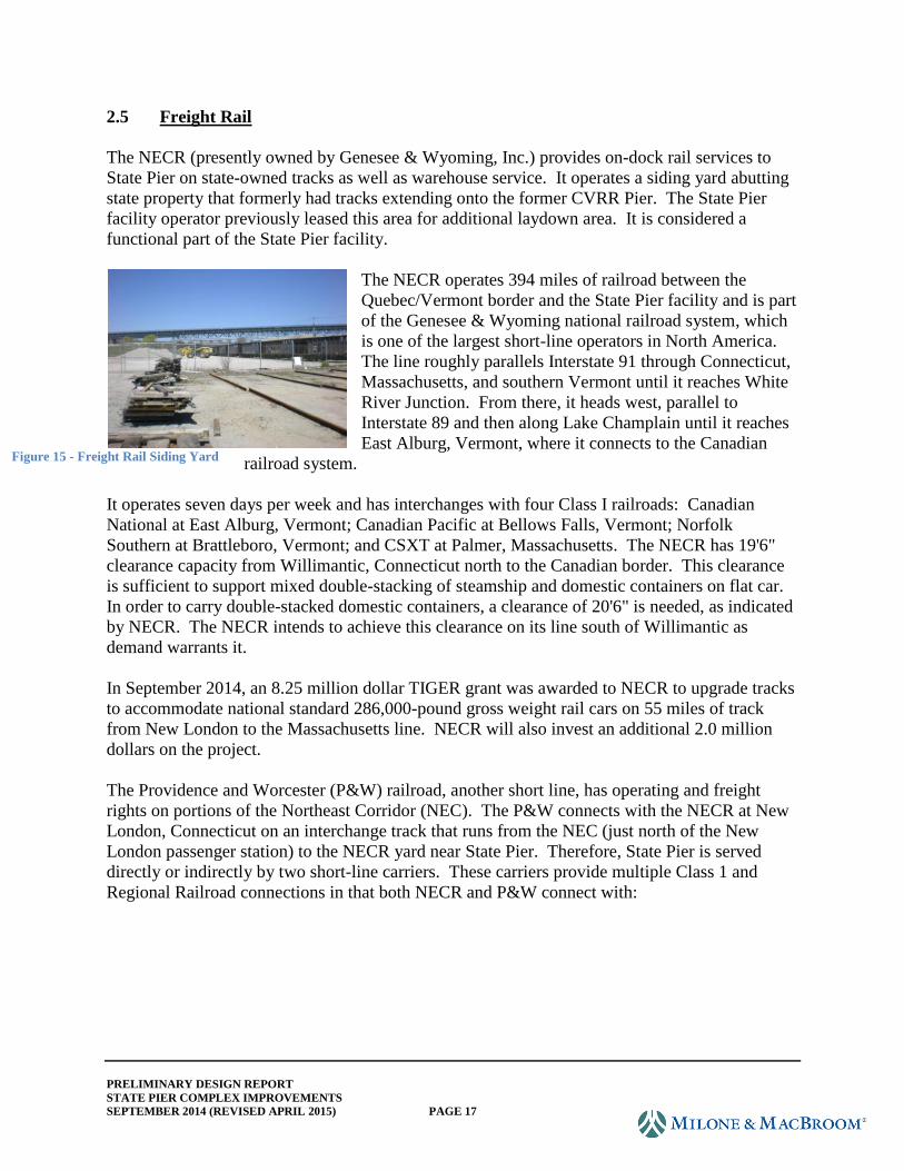
2.3.7 Mooring Dolphins
Description: Four mooring dolphins are located within the water-sheet outside of the federal
channel and angled at approximately 45 degrees to the northeast quay. Built for the U.S. Navy
for the mooring of submarine tenders in 1969, the dolphins do not have direct access to the
shoreside facility. The structures are designed with batter piles situated to provide maximum
longitudinal support for the dolphins when vessels are moored on the north side of the structures.
The batter piles protrude outward from the concrete caps of the dolphins preventing mooring
against the dolphins on the south side without the use of a mooring system that would hold a
vessel off the structure.
Condition: The steel piles are in poor condition with up to
90% section loss in some piles.
Disposition: Due to the poor condition of the piles and a
desire to improve overall navigability of the facility, it is
intended that these structures will be demolished and be
removed completely or to below the basin dredge line.
2.4 Cargo Operations and Operating Equipment
The State Pier facility is primarily operated by Logistec USA – Connecticut, Inc. under contract
to CTDOT. It utilizes stevedores provided by ILA Local 1411. It provides all the nonvessel
operating equipment for cargo handling. The equipment consists largely of a variety of forklift
trucks, yard trucks, and tractors. For calendar year 2012, State Pier handled 31 cargo vessel calls
that offloaded 111,100 metric tons of steel products. In 2013, vessel calls declined to 21 ships,
but cargo increased to 112, 838 metric tons. Through August 2014, 13 vessels have called,
offloading 106, 257 metric tons of steel. In previous years, the facility handled copper tonnage,
lumber, calcium chloride, transformers, and other heavy lift cargo along with passenger vessel
calls.
The Thames River Seafood Cooperative leases the western half of the CVRR pier.
Miscellaneous fishing gear and vehicles can be found near the fishing vessels.
Figure 14 - Mooring Dolphins
PRELIMINARY DESIGN REPORT
STATE PIER COMPLEX IMPROVEMENTS
SEPTEMBER 2014 (REVISED APRIL 2015) PAGE 17
2.5 Freight Rail
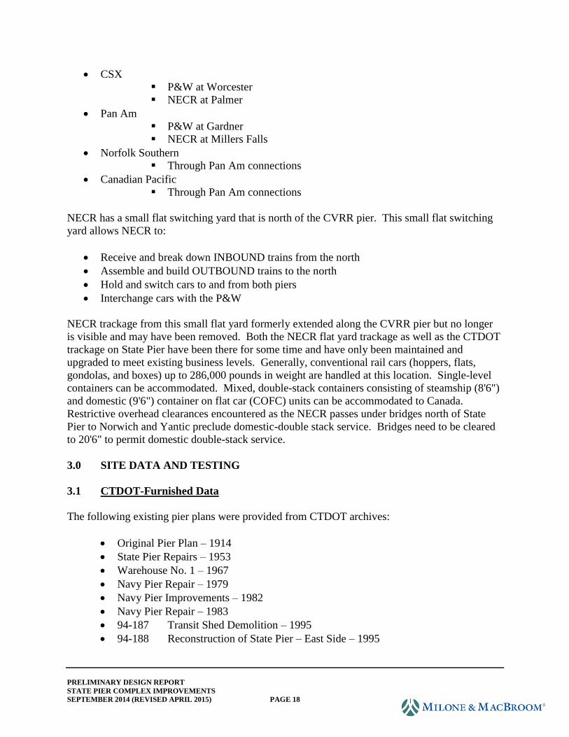
The NECR (presently owned by Genesee & Wyoming, Inc.) provides on-dock rail services to
State Pier on state-owned tracks as well as warehouse service. It operates a siding yard abutting
state property that formerly had tracks extending onto the former CVRR Pier. The State Pier
facility operator previously leased this area for additional laydown area. It is considered a
functional part of the State Pier facility.
The NECR operates 394 miles of railroad between the
Quebec/Vermont border and the State Pier facility and is part
of the Genesee & Wyoming national railroad system, which
is one of the largest short-line operators in North America.
The line roughly parallels Interstate 91 through Connecticut,
Massachusetts, and southern Vermont until it reaches White
River Junction. From there, it heads west, parallel to
Interstate 89 and then along Lake Champlain until it reaches
East Alburg, Vermont, where it connects to the Canadian
railroad system.
It operates seven days per week and has interchanges with four Class I railroads: Canadian
National at East Alburg, Vermont; Canadian Pacific at Bellows Falls, Vermont; Norfolk
Southern at Brattleboro, Vermont; and CSXT at Palmer, Massachusetts. The NECR has 19'6"
clearance capacity from Willimantic, Connecticut north to the Canadian border. This clearance
is sufficient to support mixed double-stacking of steamship and domestic containers on flat car.
In order to carry double-stacked domestic containers, a clearance of 20'6" is needed, as indicated
by NECR. The NECR intends to achieve this clearance on its line south of Willimantic as
demand warrants it.
In September 2014, an 8.25 million dollar TIGER grant was awarded to NECR to upgrade tracks
to accommodate national standard 286,000-pound gross weight rail cars on 55 miles of track
from New London to the Massachusetts line. NECR will also invest an additional 2.0 million
dollars on the project.
The Providence and Worcester (P&W) railroad, another short line, has operating and freight
rights on portions of the Northeast Corridor (NEC). The P&W connects with the NECR at New
London, Connecticut on an interchange track that runs from the NEC (just north of the New
London passenger station) to the NECR yard near State Pier. Therefore, State Pier is served
directly or indirectly by two short-line carriers. These carriers provide multiple Class 1 and
Regional Railroad connections in that both NECR and P&W connect with:
Figure 15 - Freight Rail Siding Yard
PRELIMINARY DESIGN REPORT
STATE PIER COMPLEX IMPROVEMENTS
SEPTEMBER 2014 (REVISED APRIL 2015) PAGE 18
CSX
P&W at Worcester
NECR at Palmer
Pan Am
P&W at Gardner
NECR at Millers Falls
Norfolk Southern
Through Pan Am connections
Canadian Pacific
Through Pan Am connections
NECR has a small flat switching yard that is north of the CVRR pier. This small flat switching
yard allows NECR to:
Receive and break down INBOUND trains from the north
Assemble and build OUTBOUND trains to the north
Hold and switch cars to and from both piers
Interchange cars with the P&W
NECR trackage from this small flat yard formerly extended along the CVRR pier but no longer
is visible and may have been removed. Both the NECR flat yard trackage as well as the CTDOT
trackage on State Pier have been there for some time and have only been maintained and
upgraded to meet existing business levels. Generally, conventional rail cars (hoppers, flats,
gondolas, and boxes) up to 286,000 pounds in weight are handled at this location. Single-level
containers can be accommodated. Mixed, double-stack containers consisting of steamship (8'6")
and domestic (9'6") container on flat car (COFC) units can be accommodated to Canada.
Restrictive overhead clearances encountered as the NECR passes under bridges north of State
Pier to Norwich and Yantic preclude domestic-double stack service. Bridges need to be cleared
to 20'6" to permit domestic double-stack service.
3.0 SITE DATA AND TESTING
3.1 CTDOT-Furnished Data
The following existing pier plans were provided from CTDOT archives:
Original Pier Plan – 1914
State Pier Repairs – 1953
Warehouse No. 1 – 1967
Navy Pier Repair – 1979
Navy Pier Improvements – 1982
Navy Pier Repair – 1983
94-187 Transit Shed Demolition – 1995
94-188 Reconstruction of State Pier – East Side – 1995
PRELIMINARY DESIGN REPORT
STATE PIER COMPLEX IMPROVEMENTS
SEPTEMBER 2014 (REVISED APRIL 2015) PAGE 19
94-191 Reconstruction of State Pier Road – 1996
94-193 Warehouse No. 2 - Roadway and Site improvements – 1997
94-194 Reconstruction of State Pier – West Side – 2000
94-210 Warehouse No 2 – 2000
94-216 CVRR Pier Improvements – 2004
94-219 State Pier Dredging – PD plans – 2008
The following existing bridge and retaining wall plans were provided from CTDOT archives:
103-197 Bridge No. 01609 – Rehabilitation of State Pier Road (S.R. 437) over
Central Vermont Railroad – 1985
94-163 Bridge No. 01607 – Rehabilitation of CT Route 437 over Central Vermont
Railway Track Yard – 1988 and Bridge No. 01610 – Rehabilitation of CT Route 437
over Eighth Street – 1988
3.2 Topographic and Hydrographic Survey
CTDOT provided the planimetric, topographic, and boundary survey of State Pier property.
Additionally, CTDOT is to provide top-of-rail elevations of the NECR tracks at approximately
50' intervals from the bridge over Winthrop Cove to the northern limit of the State Pier property.
Hydro Data, Inc. performed the bathymetric and side scan sonar mapping of the areas
surrounding State Pier and CVRR Pier. The following plans were created for the project:
StatePierContours.pdf
SideScanTargetsSheet1B.pdf
SideScanImagesSheet2B.pdf
SubBottomImages.pdf
State Pier Contours sheet shows the river bottom contours (one-foot interval) with elevations
based on North American Vertical Datum of 1988 (NAV 88). The hydrographic survey was
performed during April 2013 and can only represent conditions present at that time. The
accuracy of the contours is ± one inch. As a reference, the top of the curb along the outside edge
of State Pier is El. 8.83 while the top of the CVRR pier varies from El. 4.5 to El. 5.5.
Side Scan Target – Sheet 1B shows an interpretation of the raw side scan sonar data. In general,
the data shows miscellaneous objects on the river bottom that include tires, logs, cables, piles,
sheet piling, and rectangular hard objects. The sonar also determines the height of hard objects
above the riverbed to an accuracy of ± 1.0 foot. All objects noted have a projection above the
riverbed of 1.0 foot or less.
Side Scan Images – Sheet 2B shows the raw side scan sonar data. In general the yellow color
denotes hard surfaces or steep slopes. The images along the edge of State Pier show reflections
of the steel piles and the steep riprap slope up to the modular block retaining wall.
PRELIMINARY DESIGN REPORT
STATE PIER COMPLEX IMPROVEMENTS
SEPTEMBER 2014 (REVISED APRIL 2015) PAGE 20
Sub Bottom Images sheet shows the relative density of the channel bottom materials to a depth
of approximately 20 feet below the riverbed. Various profiles are shown both parallel and
perpendicular to the piers. A number of core samples were taken in the top five feet of the
riverbed and showed the material to be fine sand. No bedrock was noted to a depth of 30 to 40
feet below the riverbed. Water boring logs will be provided to Hydro Data, which can be used to
further identify the soil layers noted in the scans.
3.3 Utilities (See utility plans.)
Milone & MacBroom, Inc. contacted area utility custodians in writing for available mapping.
The CTDOT was also consulted for available plans. The design team also visited CTDOT's
headquarters in Newington and on-site office in New London to ascertain available mapping for
the site. The CTDOT's field survey located utility appurtenances visible at the surface. From
this information, an existing conditions utility layout plan was developed. Utility locations
indicated on the plan should be considered approximate, and additional research will be required
to verify the presence of utilities or resolve conflicting data. The current scope of work calls for
actual location of utilities in the field with the assistance of a locating contractor. It is
recommended that this effort be deferred until the Preliminary Design plans are reviewed by
CTDOT, and potential utility impacts are better understood. In addition, many existing utilities
will be displaced or impacted by construction. With this in mind, it would be prudent to better
understand the impacts prior to performing test pits, so as to effectively prioritize the work.
Going forward, it may be necessary to engage utility contractors to field test certain utilities such
as buried electric and water lines to determine whether the facilities are active, inactive or have
been previously abandoned.
3.3.1 Existing Utilities
3.3.1.1 Transmission Lines
An AT&T underground fiber optic transmission line enters the site in the vicinity of the
railroad bridge north of State Pier. The transmission lines then run east-west north of
Warehouse #2, then along former 8th Street to a small brick building at the east end of the
road. From there, the lines run under the Thames River to Groton.
The transmission line serves as a major communication link between New London and
Groton, and beyond. Disruption to this facility during construction of the planned
improvements is likely. The preliminary design attempts to minimize or avoid impacts to
this utility. At this juncture a conservative (shallow) depth has been assumed for design
purposes. The Preliminary Engineering (10%) drawings have been revised to potentially
avoid the fiber optic. The administration building has been shifted, as well as a proposed
retaining wall along the south side of State Pier Road. While the plans may depict our
avoiding the utility with physical assets, the proposed grade changes will affect the fiber
optic bury depth. For instance, while the retaining wall was shifted to avoid the fiber
optic, a significant amount of fill will be placed over the utility to accomplish the
PRELIMINARY DESIGN REPORT
STATE PIER COMPLEX IMPROVEMENTS
SEPTEMBER 2014 (REVISED APRIL 2015) PAGE 21
intended improvements. Extensive communication and coordination with AT&T, the
utility custodian, will be necessary to understand any associated design ramifications.
The test pit program described in the above paragraphs may serve to identify the depth of
this utility unless better records can be obtained.
Yankee Gas has a transmission line in the project vicinity. The line runs down Thomas
Griffin Road before crossing Winthrop Cove toward Water Street.
3.3.1.2 Former City Street Utilities
The site encompasses a former City of New London residential neighborhood that has
previously been abandoned and deeded to the state. Both water and sewer utilities are
present along the former local roadway network. Water and sewer mains run north-south
along Fraser Street and east-west along 10th Street and 12th Street. Few service
connections to the former neighborhood were shown on previous plans of the site and
may have been removed during the demolition of the neighborhood.
The water and sewer mains running north-south along Fraser Street connect to the water
and sewer located along 8th Street to the north and 12th Street to the south. These utilities
located on 12th Street connect to the network of water and sewer utilities south of the
neighborhood just upland of the pier. Due to these connections with active systems, it
will be important to determine to what degree the former neighborhood utilities are still
active and in what condition those utilities are.
The survey indicates that a water main is located along 16th Street connecting to a water
meter on the north side of 8th Street and terminating in the vicinity of the fire hydrant on
10th Street. This water main cannot be found on record plans of the area, and there are no
manholes or water gates that indicate the presence of a water main in this area. Whether
or not there is in fact a water main on 16th Street needs to be determined.
Overhead utilities parallel the east side of 16th Street. Record plans indicate the presence
of a light pole on Fraser Street, and survey confirms the pole is still present. It is unclear,
however, if it is still energized.
Following demolition of the former neighborhood, high mast luminaires were installed on
the site. A single luminaire was installed near the intersection of Fraser Street and 10th
Street in conjunction with additional lighting installed along the northeast quay. The
luminaire located in the former neighborhood is connected by underground conduit to the
additional lighting further down the hill and along the quay.
PRELIMINARY DESIGN REPORT
STATE PIER COMPLEX IMPROVEMENTS
SEPTEMBER 2014 (REVISED APRIL 2015) PAGE 22
3.3.1.3 Utilities Upland of Pier
8th Street and State Pier Road
Water
There is one water main that runs east-west along 8th Street originating from the 6" water
main that runs north-south on the western side of the site. The water main continues
along 8th Street until it reaches a water meter on the north side of the road at the
intersection with 16th Street. It is unclear if the water main continues beyond this point.
There is a junction at Fraser Street where the water main servicing the former
neighborhood connects.
The available mapping and survey of this area causes some confusion as to the exact
location of the utilities in this corridor and their connections to other utilities on the site.
There is a segment of water main shown in the survey provided that does not appear in
any of the available mapping. It is a short segment along the north side of 8th Street
beginning near the Fraser Street intersection and does not appear to connect with any
observed manholes or water gates. Neither does it correspond with the location of the
water main shown on older plans.
Sewer
A 20" sewer outfall runs east-west along 8th Street with an outlet on the shore of the
Thames River. The outfall originates at a pump house located outside of the project
limits at the end of Thomas Griffin Road. An 8" sewer main runs parallel to the outfall
and ends at the intersection of 8th Street and Fraser Street. It connects to the former
neighborhood to the south and a sewer main that goes north toward an unknown
terminus. There are a number of conflicts between the survey and the available mapping
over the exact locations of these sewer mains.
Overhead Utilities
Overhead wires parallel the northerly side of 8th Street before exiting the site to the north
where State Pier Road intersects 8th Street. In addition to the overhead wires, there are
streetlights along the northern side of State Pier Road east of the railroad tracks. The
streetlights switch to the southern side of the road to the west of the tracks.
Warehouses
As discussed in the previous section, there are a number of utilities running along the
north side of Warehouse #2. In addition to these utilities, there are also a number of other
utilities running north-south on either side of the warehouses.
Storm Drainage
There is a fairly extensive storm drainage system on the project site. East of the railroad
tracks, the storm drainage system begins at 8th Street and extends south toward the head
of the pier. West of the tracks, the storm drainage system begins on the north side of
PRELIMINARY DESIGN REPORT
STATE PIER COMPLEX IMPROVEMENTS
SEPTEMBER 2014 (REVISED APRIL 2015) PAGE 23
Warehouse #1 and continues down around the west side of the warehouse. The storm
drainage systems on both sides of the warehouse join with the storm drainage at the head
of the pier. Overall, the storm drainage system flows to the south and discharges to the
Thames River between State Pier and the CVRR Pier.
Water
A single 6" water main enters the site at the northwest corner and runs north-south down
the western side of the site before it splits just south of the two smaller warehouses and
runs east-west.
A 12" water main origination from State Pier Road enters the site north of Warehouse #2
on 8th Street. The water main turns west and runs north-south along the western side of
Warehouse #2. It then turns to the east between the two warehouse buildings and runs
north-south along the eastern side of the tracks toward the head of the pier.
Sewer
A 20" sewer outfall and a 15" sewer main run north south along the western side of the
warehouse. The 15" sewer main flows to the south toward the pump house located near
the end of Thomas Griffin Road. The 20" outfall turns to the east along 8th Street before
ending at the Thames River.
Overhead Utilities
In addition to the underground utilities, there are overhead utilities on both the east and
west sides of the warehouses.
Head of the Pier
The head of the pier has a high concentration of utilities that service the piers,
warehouses, and administration buildings.
Storm Drainage
The storm drainage on the east and west sides of Warehouse #1 is connected by a series
of catch basins, manholes, and reinforced concrete piping across the head of the pier.
The field survey matches fairly well with the available mapping; however, there are two
manholes located near the southwest corner of Warehouse #1 that have a number of pipes
tying into them that have no apparent terminus.
Water
There are a number of water mains located in this area. The water main servicing the
former neighborhood enters the head of the pier near the administration building on the
northeast quay before it splits into multiple lines. It appears that these lines previously
connected to the administration building and the northeast quay wall. While the
administration building was connected to the newer 12" water main discussed in the
previous section that runs along the east side of the warehouses, it is unclear if the quay
wall still derives its water source from the neighborhood water main or if that too was
PRELIMINARY DESIGN REPORT
STATE PIER COMPLEX IMPROVEMENTS
SEPTEMBER 2014 (REVISED APRIL 2015) PAGE 24
connected to the new main. A 6" water main that runs north-south along the west side of
the two warehouses crosses the head of the pier and previously provided water to State
Pier. When State Pier was reconstructed, connections to this main were cut and the water
supply on State Pier is now provided by the 12" water main that originated on State Pier
Road. Warehouse #1 may still derive its water supply from the older 6" water main.
The 6" water main continues toward the northeast quay, but there is no known connection
to any utilities in that area.
Sewer
The sewer runs east-west across the head of the pier connecting with one of the sewer
mains running north-south west of the warehouses and the sewer main that serviced the
former neighborhood. This sewer line previously serviced the northeast quay and State
Pier. The sewer line on the quay has been abandoned and the sewer on State Pier
removed when the pier was reconstructed. Based on available mapping, the gravity
sewer flows toward the pump house located to the west on Thomas Griffin Road.
Overhead and Underground Electrical Utilities
The overhead wires that run down the east side of the railroad tracks connect to
underground electrical lines at the head of the pier. There is a transformer located at the
junction of the northeast quay and State Pier. Most of the underground electrical lines
appear to feed into this transformer including the electrical lines for the recently installed
high-mast luminaires. The electrical lines for State Pier are also assumed to connect to
this transformer as most mapping shows the underground conduit ending just short of the
transformer's location. This will have to be confirmed.
There are a number of underground electrical lines at the head of the pier shown in the
available mapping that do not have clear connections either to buildings or to other
electrical facilities. There is a short electrical line that connects to Warehouse #1 but
terminates just west of the railroad tracks.
The lights on CVRR pier are connected to the transformers located just south of the two
smaller warehouse buildings. The source of the high-mast luminaires in that area of the
project site is unclear.
Northeast Quay
Water
Two water mains run along the northeast quay to service a series of hydrants and fresh
water connections. Available mapping indicates that these water lines are supplied by the
water main that runs north-south through the former neighborhood. The main splits near
the southwest corner of the administration building into a fire line and a fresh water line.
It is unknown if the fresh water line or fire hydrants are still active.
PRELIMINARY DESIGN REPORT
STATE PIER COMPLEX IMPROVEMENTS
SEPTEMBER 2014 (REVISED APRIL 2015) PAGE 25
Sewer
A sewer line runs the length of the quay and connects to the sewer system that flows to
the west along the head of the pier. This sewer line appears to have been abandoned.
Underground Electric
Underground conduit runs along the edge of the quay providing power to a series of
electrical boxes. This conduit connects to a transformer on the north side of the
administration building. Recently, this transformer was removed and the electrical lines
have been pulled leaving the conduit in place.
The power for the high mast luminaires along the quay is supplied by the transformer
located at the junction of the quay and State Pier.
There are a number of electrical lines that connect to the administration building. On the
south end of the building, there is a connection to the underground lines running north-
south just east of the railroad tracks. There is a second connection on the east side of the
building that has no known terminus north of the building. The building had previously
been connected to the transformer located to the east which has now been removed.
3.3.1.4 Utilities Associated With Pier
There is limited mapping available for the utilities on both State Pier and CVRR Pier.
Survey located a number of water gates and handholes on both piers; however, it is
difficult to reconcile the survey with the mapping resulting in some water gates and
handholes still not properly associated with a particular utility. The unknowns will have
to be resolved as the design progresses.
State Pier
Water
There are a number of water mains on State Pier. On both the east and west side of the
railroad tracks there are two abandoned water mains. Two new lines, a fire line and a
fresh water line, were installed along the east side of the tracks when the pier was
reconstructed and these lines now supply the fresh water outlets and fire hydrants on both
sides of the pier.
Electrical
The electrical conduit for the pier originates from the transformer located at the head of
the pier at the southern end of the northeast quay. Conduit runs down the center of the
pier between the railroad tracks to supply power for the luminaires. Conduit for the
outlets, navigation lighting and heat-tracing runs along the perimeter of the pier.
PRELIMINARY DESIGN REPORT
STATE PIER COMPLEX IMPROVEMENTS
SEPTEMBER 2014 (REVISED APRIL 2015) PAGE 26
CVRR Pier
Water
The water on CVRR Pier is supplied by the 12" water main that also supplies water to
State Pier. According to available mapping, the water main runs down the western side
of the pier with a number of hydrants along the bulkhead.
Electrical
The available mapping for the underground electrical lines on CVRR Pier comes in the
form of electrical schematics, which represent the types of cables and locations of
connections rather than the exact physical location of the conduit. It is clear, however,
that the electrical conduit is located within the same utility corridor as the water main and
supplies power to the luminaires and outlets along the pier. These schematics also show
that additional lines were installed for future communications and security purposes. No
additional mapping was available to determine if these lines have been utilized for these
purposes since their installation. The transformers located south of the two small
warehouses provide the power source for CVRR Pier. There are also two high mast
luminaires at the head of CVRR Pier. It is not clear how these are incorporated into the
electrical system.
3.4 Stormwater Management
3.4.1 Existing Conditions
The State Pier Complex has an existing stormwater management system that routes much of the
intercepted runoff to the Thames River. The existing drainage network captures the buildings'
and roadway/storage area runoff and conveys it to the river via three point discharge locations.
The discharge invert elevations range from 1.56 to 4.03 feet. All existing discharges are below
the 100-year flood elevation of 11.0 feet based on Federal Emergency Management Agency
(FEMA) map 09011C0502J dated November 15, 2011. Runoff from approximately 11 acres of
the site drains to a single discharge location located between the two piers. The other two
locations, located in the northeast corner adjacent to the state boat launch, capture a combined
total of about three acres of the site including a roadway and small parking lot. The remaining
drainage areas reach the Thames River via overland sheet flow. The State Pier routes stormwater
runoff to numerous scuppers that outlet directly to the Thames River, and runoff from the CVRR
Pier discharges to the river strictly by overland flow.
Based on our research and site visits, there appear to be no stormwater quality measures on the
project site.
3.5 Geotechnical Investigation
Mueser Rutledge Consulting Engineers (MRCE) in consultation with other members of the
design team developed a pilot subsurface investigation program in order to ascertain soil
conditions for design purposes. Available boring data was furnished by CTDOT, and the boring
PRELIMINARY DESIGN REPORT
STATE PIER COMPLEX IMPROVEMENTS
SEPTEMBER 2014 (REVISED APRIL 2015) PAGE 27
locations are shown on the boring location plan in Appendix C. Boring logs from previous
explorations, both in-water and for upland, were reviewed. With consideration of required
design criteria and available information, a pilot investigation was developed and submitted to
CTDOT for concurrence.
The pilot investigation included 13 borings, six of which were located over water and seven on
land, to supplement existing subsurface information. The borings were made by New England
Boring Contractors between July 8 and August 22, 2013. MRCE provided continuous inspection
of all borings, and our inspector prepared a Daily Field Report and a log for each boring. All
samples were delivered to our laboratory for review of field classification and testing.
3.5.1 Admiral Shear State Pier
MRCE performed a subsurface investigation at the pier in 1992, and the subsurface information
from that investigation was used to evaluate the impact of proposed berth deepening on the
existing pier. The paved surface of the pier lies at approximately El. 8 (NAV88). Borings made
within the infill area show a 10- to 20-foot-thick layer of loose to medium compact fill overlying
medium compact to compact sands with trace to some gravel and silt, with boulders underlain by
granitic gneiss bedrock. A discontinuous deposit of organic silty clay up to 10 feet thick was
encountered within the middle third of the length of the pier. Borings show that the rock surface
slopes down from north to south along the pier from approximately El. -45 near shore to about
El. -130 near the south end of the pier.
The Master Plan for the New London State Pier Facility includes dredging along both sides of
the State Pier to deepen the berth along the east side of the pier to approximately El. -44 and
along the west side of the pier to about El. -39. Dredging to these depths along the edge of the
pier will extend approximately 14 feet and nine feet below the existing mudline, which is about
El. -30 adjacent to the pier. This will undermine the existing slope below the relieving platforms
requiring that the existing slope be supported prior to dredging.
During the field reconnaissance site visit, settlement of the expansion joint between the east side
relieving platform and filled area of the pier was observed. The joint edge on the filled section
of the pier has settled. Drawings for the reconstruction of the east side deck of the pier show that
the concrete deck of the filled area of the pier is supported on the precast retaining wall, which
bears on the underlying rock and boulder fill. The sizes of the rock and boulders comprising the
fill are not known. The movement of the joint could be from settlement of the precast footing
from possible migration of the gravel into the pore spaces of the rock and boulder fill and/or
slope movement.
We believe it will not be economical to drill through the footing of the precast retaining wall and
rock and boulder fill to support it on piles or perform low mobility grouting. We recommend
that consideration be given to constructing a transition slab and evaluating supporting one end of
the slab on a bracket anchored to the end of the relieving platform. The other end is supported
on a strip footing bearing in the fill. The transition slab should be reinforced to span the distance
between both support points.
PRELIMINARY DESIGN REPORT
STATE PIER COMPLEX IMPROVEMENTS
SEPTEMBER 2014 (REVISED APRIL 2015) PAGE 28
3.5.2 CVRR Pier (Long Dock)
Subsurface conditions at the CVRR Pier revealed by the recently completed pilot boring program
are similar to those described for the State Pier except that the rock surface is at a higher
elevation. The rock surface typically slopes down from north to south ranging from about El.
-30 near shore to about El. -80 at the south end of the pier. One boring that was cored through
the granite block retaining wall at the southwest corner of the pier where the width changes,
indicated that the wall is founded at approximately El. -18.
The Master Plan shows that the berthing areas along the east side of the pier will be dredged to
El. -39 and to about El. -24 along the west side. These elevations extend below the bottom of the
existing granite block retaining wall. A new wall will be required to deepen these berths.
3.5.3 Center Shoreline and Pile-Supported Wharf Platform Between Piers
Borings show that rock lies at approximately El. -50 or about 11 feet below the planned dredge
depth. A four-foot layer of boulders was encountered above rock. This depth of overburden is
insufficient to provide lateral support for cantilever sheeting bulkhead.
3.5.4 Northeast Pile-Supported Platform and Quay Sheet Pile Bulkhead
Borings show that the soil profile is generally comprised of loose to compact coarse to fine sand
with gravel to coarse to fine gravel with some coarse to fine sand, with trace silt overlying
bedrock. Bedrock was encountered at about El. -80 at Boring M-2 made toward the southwest
end of the quay wall. Boring M-1 made at the planned northern extension of the quay wall was
advanced to El. -103 without encountering bedrock.
Available drawings show that the sheet piling for the existing bulkhead was driven to El. -40 and
is anchored by tie-rods to a sheet pile deadman. Dredging adjacent to the State Pier will extend
to about El. -44 and transition to the northeast along the existing timber pile platform and quay
wall to about El. -29.
3.5.5 Northeast Quay Sheet Pile Bulkhead
The existing quay wall sheeting has insufficient embedment for a dredge depth to El. -29. The
condition of the existing tie rods, connections, and deadman is unknown at this time and should
be investigated before final design commences.
3.5.6 Northwest Quay Stone Bulkhead
Borings show a layer of organic deposits underlain by loose to compact sands and gravel with
trace to some silt over bedrock. The rock surface was encountered at approximately El. -30. The
dredged bottom in this area will extend to about El. -24.
PRELIMINARY DESIGN REPORT
STATE PIER COMPLEX IMPROVEMENTS
SEPTEMBER 2014 (REVISED APRIL 2015) PAGE 29
The preliminary geotechnical report for structures and roadways, including foundation design
parameters, boring location plan, final boring logs, and laboratory testing results, is provided in
separate reports.
4.0 FUNCTIONAL AND OPERATIONAL PLANNED IMPROVEMENTS
This section presents a description of the planned improvements to the State Pier facility. Please
refer to the illustrations entitled Master Plan and Functional Use Areas on the following pages
for the locations of the components and functions of the facility.
4.1 Site Access, Upland Facilities, and Yard Operations (See Site, Grading, and Security
plans.)
The proposed improvements are directed toward upgrading the State Pier facility by enhancing
its flexibility to handle a wide variety of break-bulk and neo-bulk cargos as well as provide the
capability to accommodate container operations. Another objective is to promote cargo transfer
between vessel and rail.
4.1.1 Site Access
To meet these objectives, access to the terminal by vehicle is shifted to State Pier Road where the
public road will end and the secure Part 105 Facility begins. State Pier Road is to terminate in a
cul-de-sac with public access to the state boat launch to remain until such time as cargo volumes
warrant active storage in that location, requiring relocation of the boat launch. Access for the
Amtrak bridge tenders and maintenance crews will also be provided by this route.
A canopied gate plaza east of the cul-de-sac will control all routine vehicular ingress and egress
to the port terminal, as well as have the capability to meet U.S. Customs and Part 105 security
requirements. A new administrative building will adjoin the gate facility with associated parking
that is both available to the on-site employees and visitors and outside of the Part 105 secure
facility. A separate guard house will be located near the curb line. Port operations, CTDOT
administrative activity, Customs, and a security control center would be housed in the building.
As is now common in port operations, it is assumed that the gate facility will be controlled by a
Terminal Operating System that enables streamlined contact with terminal customers for real-
time planning and operational control that optimizes utilization of labor, yard space, and
handling equipment to maximize efficiency and productivity. The gate area will contain
provision for continuous closed circuit TV monitoring, communication ducts, Radiation Portal
Scan (RPS) and Vehicle and Cargo Imaging System (VACIS) monitoring stations, and a Custom
inspection lane with turnout. A truck scale will be included between the ingress and egress
lanes. The gate plaza will be equipped with gates near the cul-de-sac that can be closed at the
end of the business day or for security reasons. Traffic flow past the gate plaza will use a new
access road that transitions the grade change using new retaining walls (see Structures plans).
Thereafter, traffic will be primarily controlled by portable concrete barriers, illuminated signage,
and/or pavement markings. In order to maximize site flexibility for cargo operations, permanent
above-grade installations are being kept to a minimum.
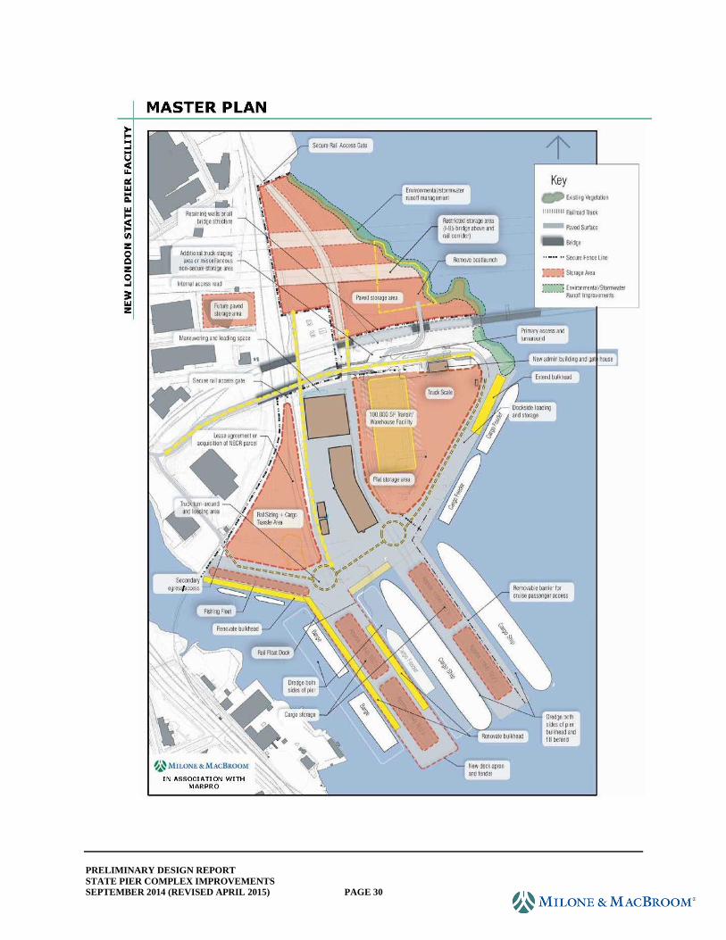
PRELIMINARY DESIGN REPORT
STATE PIER COMPLEX IMPROVEMENTS
SEPTEMBER 2014 (REVISED APRIL 2015) PAGE 30
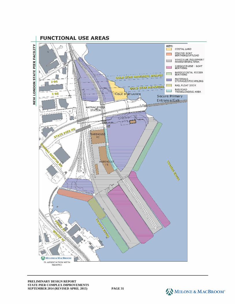
PRELIMINARY DESIGN REPORT
STATE PIER COMPLEX IMPROVEMENTS
SEPTEMBER 2014 (REVISED APRIL 2015) PAGE 31
PRELIMINARY DESIGN REPORT
STATE PIER COMPLEX IMPROVEMENTS
SEPTEMBER 2014 (REVISED APRIL 2015) PAGE 32
A typical truck movement after terminal upgrades are completed would involve a preregistration
process with the terminal operator where documentation for cargo pickup or drop-off would
occur, and times for arrival would be determined. Upon arriving at the terminal at a
predetermined time, the driver would enter the entry lane, scan a driver's license and/or
Transportation Worker Identification Credential (TWIC) card, provide a booking number or scan
a bar code for the transaction, and obtain a gate pass from terminal operations to enter and be
directed to a predetermined pickup or drop-off location on site. The cargo movement would
occur, and the truck returns to the gate plaza exit lane where the truck will be cleared to exit or
be inspected, if warranted, prior to leaving the terminal.
4.1.2 Upland Facilities
The most significant site modification proposed in the design is lowering the grade in the knoll
area that adjoins the northeasterly quay. Due to the elevation differential as the topography
climbs from the waterfront, this area currently is difficult to use for storage. However, as it is
located at the head of State Pier and adjoins the northeasterly quay wall, its location is prime near
the dock laydown area. The knoll also restricts east-west movement to the warehouses.
Reclaiming this area to facilitate cargo movement from State Pier, the warehouses, rail siding,
and the northeasterly quay wall will greatly improve the operational flexibility of the terminal.
Movements north-south from the piers will have greater access to storage areas, an additional
near-dock storage area will be created, and east-west movements to/from the warehouses and rail
sidings will be possible. Storage near the entry plaza should also promote efficiency of
movement and operational flexibility. A test layout for a container yard in this area yielded
1,100 TEUs (Twenty-Foot Equivalent Units) stacked three-high with generous access lanes.
Provision is also made in the site design to add a 90,000-square-foot warehouse in this area
should port operations warrant.
The balance of the terminal south of State Pier Road will receive minor grading to match the
elevations of the piers and include surface treatments to facilitate forklift and truck movements.
The objective is to create a relatively consistent, unobstructed surface elevation, rising gradually
from 8.0'± at the head of the pier up to elevation 12.0' near the rear of the Administration
building. The gradual change in elevation is to facilitate movement for as many types of cargo
as possible. The design assumes surface loadings that accommodate tractor trailers, forklifts,
reach stackers, and a mobile harbor crane. The design also assumes periodic inundation from
storm events. While the FEMA 100-year flood elevation is 11', given the site's cargo
transshipment function, occasional pier and site flooding can be accommodated in the design and
operational procedures. The main floor of the administrative building is to be built above the
projected flood level.
The State Pier Master Plan envisioned incorporating the NECR railroad siding into the storage
area at the head of the CVRR Pier. No site improvements for the rail siding area are included in
this design as no agreement has been formalized between CTDOT and NECR. However,
extension of rail from the siding to CVRR Pier is included in the design. As such, a single track
is being proposed down the center of the pier. Additional survey after the preliminary design
phase will be required to determine the track connection geometry.
PRELIMINARY DESIGN REPORT
STATE PIER COMPLEX IMPROVEMENTS
SEPTEMBER 2014 (REVISED APRIL 2015) PAGE 33
The terminal area north of State Pier Road is envisioned to continue to be used for longer-term
storage of cargo. Regrading the site to create a consistent surface, providing positive drainage,
adding paved access from the south terminal area, adjusting internal fencing to create storage
yards, and vegetation management are among the improvements proposed for the north terminal
area.
4.2 Utilities
Preliminary Design plans depict proposed utilities based on an initial assessment of various
needs at the facility. MMI conducted meetings with and interviewed CTDOT staff to understand
the desired utility accommodations. The need for new utilities is based on specific needs for
cargo vessels and upland operations and is also due to construction impacts on existing facilities.
The previous State Pier Needs & Deficiencies Study was consulted with regard to probable or
likely future pier uses. Following is a summary of the proposed utility systems.
Water
Water is necessary for domestic use at the administration building, for fresh water for vessels at
berthing, and for fire protection throughout. The proposed plans indicate tapping an existing 12-
inch water main in the vicinity of Former 8th Street where it intersects the state-owned rail. The
water main would be extended to provide service to the administration building, and a looped
system would be created on site to serve the piers as well. Hydrants would be provided for
throughout the upland area. At the head of the piers, separate water lines provide water for a
system of hydrants and freshwater connections. At this time, the design does not include
extending water service to the north of State Pier Road either for domestic or fire protection
purposes. If desired, a water main extension could be installed within the existing gravel access
road, which parallels the east side of the tracks and provides connectivity between the pier head
and the yard north of State Pier Road.
Sanitary
A preliminary sanitary sewer layout is depicted on the Preliminary Design plans for service to
the Administration building. The sewer lateral would serve the lower level of the proposed
building, discharging to the existing sewer in Former 8th Street. Sanitary sewers are proposed for
CVRR Pier and State Pier as well. On the pier, the sewer would be a force main capable of
receiving pumped effluent from vessels in berth. Off the pier, the force mains would discharge
to the existing gravity sewer system on site. The sewer force main is proposed near the center of
CVRR Pier to serve both sides of the pier. On State Pier, separate force mains are proposed
along each side of the pier to avoid having to excavate through the concrete deck and track
system along the center of the pier. It would be expected that most vessels would have the
capability to pump from their holding tanks, thus the project does not propose a vacuum system.
Electric
Going forward, consultation with the power company will be necessary to determine how to best
serve the site. Preliminary Design plans indicate all new services to be underground to minimize
PRELIMINARY DESIGN REPORT
STATE PIER COMPLEX IMPROVEMENTS
SEPTEMBER 2014 (REVISED APRIL 2015) PAGE 34
conflicts with port operations. Power enters the site from several locations. The schematic
layout shown for preliminary design purposes involves taking power from the overhead service
north of Former 8th Street and south of State Pier Road. From relocated Pole No. 12810, aerial
service would go underground to serve the Administration building, as well as provide for
illumination in the parking lot, State Pier Road, the cul-de-sac and driveway to Amtrak, and the
Connecticut Department of Energy & Environmental Protection (CTDEEP) boat launch.
South of State Pier Road, underground electric is proposed from an existing service located south
of the small steel frame warehouse adjacent to the NECR tracks. A number of high mast light
poles are affected by the work. There are several transformers on site. The transformer at the
head of State Pier (northeast corner) is to be removed and relocated for enhanced operations.
Much of the upland lighting system is fairly new, so it is anticipated that light poles and
luminaires will be relocated as appropriate. The preliminary design depicts preliminary light
pole locations based on intended circulation and general spacing of existing light pole pattern.
Final design will require a study of photometrics to refine light pole number, type, and locations.
Power to the piers will serve to energize the heat trace system for water utilities, as well as the
navigation lighting and ship-to-shore power receptacles. Stub up connections for power
throughout the upland area may be necessary if there is a demand for storage of refrigerated
containers (or reefers) on site. Further coordination with CTDOT would be necessary during
final design to determine whether such services should be incorporated at this time. Power will
be fed underground to the truck weigh scale, guard house, and other ancillary structures.
Communications
The preliminary design assumes communications will be provided via the existing AT&T fiber
optic network. Service to the existing Administration building originates from a telephone
manhole at the intersection of Former 8th Street and Former 6th Street. Preliminary plans assume
the same connection point for service to the proposed Administration building and to the truck
weigh scale. It is assumed services to the guard house will be fed from the Administration
building, including electric, telephone, CCTV, and communications.
Gas
A gas transmission main traverses the southwest corner of the state-owned property. Based on
our research, there is no gas service to the site. While having gas service provides for additional
flexibilities in design, there are presently no plans to extend gas service to the facility under this
project.
4.3 Stormwater Management
Under proposed conditions, the project site will include a vehicle entry, screening and staging
area, driveway, traffic- and security-related improvements, and revised site layout and grading
scheme to support increased cargo handling, storage availability, and accessibility.
The area north of Amtrak and under the Gold Star Bridge will contain layout and driveway
improvements with minor grading modifications. The majority of the proposed earthwork will
PRELIMINARY DESIGN REPORT
STATE PIER COMPLEX IMPROVEMENTS
SEPTEMBER 2014 (REVISED APRIL 2015) PAGE 35
take place in the area south of Amtrak in the knoll area. At the waterfront, CVRR Pier will be
raised from its lowest point at 4.5' to a maximum of 8.0', and stormwater will continue to sheet.
The new pier surface will include scuppers to discharge the overland flow. State Pier will
remain at the existing grade with stormwater routed to scuppers along the proposed curb.
The proposed stormwater management system will utilize the existing point discharge locations
to the Thames River and maintain existing drainage patterns as much as possible. Based on the
proposed grade changes, the tributary area to the outlet FES 1 between the piers will be increased
to approximately 12.5 acres and will need to be extended approximately 60' to accommodate the
proposed improvements with the invert elevation being lowered from 1.82' to an elevation below
the proposed waler for the anchor wall at the Central Wharf structure. The other two discharge
locations, FES 2 and FES 3, will discharge runoff intercepted from a tributary area of
approximately 6.5 acres with no expected changes to the invert elevations. As with the existing
conditions, all the discharge elevations will be below the 100-year floodplain elevation of 11.0'
but above the mean high tide elevation of 0.92' NAVD88. Tidal gates/valves will be added to
the discharge pipes to help guard against surcharging the stormwater management system under
extreme or tidal storm events.
As part of the proposed improvements to the site, best management practices will be used to
provide for stormwater quality. As proposed, stormwater will be collected by deep-sump catch
basins and a heavy/industrial duty linear trench drain and then routed through underground
piping to one of the several discharge points. Sediment chambers and proprietary hydrodynamic
separators will be added to the proposed drainage network in advance of discharge locations to
remove suspended solids and floatables for enhanced water quality upon discharge.
4.4 Wharf Structures and Waterfront Cargo Operations
For any port facility, the available alongside depth, geometrical and operational configuration,
and service condition of its wharf facilities are essential for providing successful operations.
These scarce resources dictate which type of vessels can access the facility, as well as which
cargo is suited for movement across the docks. The concepts set forth for this project provide the
State Pier facility with almost 5,000 feet of available deep-water berthing in three areas and
another 345 feet of berthing for shallower draft vessels. State Pier is a finger pier that provides
two 1,000-foot pier faces and on-dock rail. The east face will be dredged to 40' depth (below
MLLW) and the west face to -35' depth. Improvements to the pier will be required to
accommodate the dredging, as discussed in Section 2.0. It is also recommended that differential
settlement of the pier's working surface be addressed in addition to other previously deferred
maintenance items. Two condemned timber marginal wharf structures on either side of State
Pier are to be removed, and new construction will be installed to accommodate the deeper dredge
and to improve site functionality. The east side of State Pier will continue to accommodate the
deepest draft vessels (up to Panamax size ships, length 950', width 106', draft of 39.5') calling on
the terminal and will be retrofitted to accommodate reasonably expected future cargo operating
equipment, inclusive of mobile harbor crane(s) at some future date. Please refer to the
illustration entitled "Waterfront Structures" on the following page for location of the structural
components.
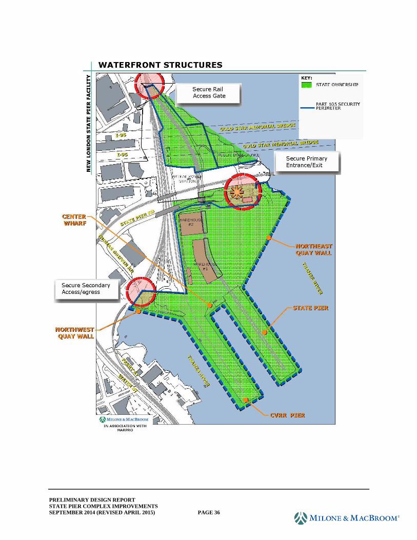
PRELIMINARY DESIGN REPORT
STATE PIER COMPLEX IMPROVEMENTS
SEPTEMBER 2014 (REVISED APRIL 2015) PAGE 36
PRELIMINARY DESIGN REPORT
STATE PIER COMPLEX IMPROVEMENTS
SEPTEMBER 2014 (REVISED APRIL 2015) PAGE 37
The CVRR Pier is also a 1,000-foot finger pier, but its current deteriorated condition requires
extensive rehabilitation or reconstruction to restore operational use and to accommodate the
planned dredge deepening. The pier surface, currently varying from elevation 4.5' to 5.5', is
regularly overtopped during storm events. The alternatives studied propose raising the pier
finished grade to elevation 8.0', which is approximately 1' lower than State Pier. The east face
will be reconstructed to provide a continuous berth face approximately concurrent with the
existing pier head easternmost limits and will be dredged to -35' depth. The west face will be
reconstructed to the same general shape as it presently exists and will be dredged to -20' depth.
The concept also provides for extension of the existing yard single track railroad spur onto the
pier. This will require regrading the yard side approaches to the pier to allow extending a
railroad spur. It is assumed that the rail would support conventional cargo operations and could
also support a rail-to-barge operation. Utilities, lighting, and new/improved fendering and
mooring structures are also included in the conceptual improvements. The east face of the pier
will accommodate American Marine Highway (AMH) vessels while the west side will
accommodate ocean tugs, barges, coasters, and shallower draft vessels. See Functional Use
Areas illustration.
The northeast quay wall provides an additional 914 feet of dockage with dredging from -40'
depth at its southern end to -30'depth at the north end. The existing structure will require the
placement of a new line of combination sheeting with tiebacks to accommodate the deeper
dredge. Extension of the quay wall 260 feet to the northeast creates a total of 914 feet of
dockage. Removal of the existing mooring dolphins is part of the improvements to this area that
will create an unobstructed water sheet and access to the navigation channel. The improved quay
wall will be able to accommodate most AMH vessels, barges, tugs, and coaster freighters. See
Functional Use Areas illustration.
The northwest quay wall provides 345 feet of dockage for shallower draft vessels, with a planned
dredge depth of 16.9 feet (MLLW). This would provide potential berthing for the fishing fleet
and other shallow draft vessels such as tugs, small barges, or maintenance vessels.
Several alternatives were considered under the preliminary engineering phase of the project for
improvements to the port waterfront facilities that are required to accommodate the proposed
harbor dredging and satisfy future functional and operational needs. Alternatives considered
were outlined in a Preliminary Engineering submission, including 10% plans and a report dated
November 8, 2013. The various alternatives were discussed and vetted at a design review
meeting on February 25, 2014. At this meeting, CTDOT concurred with all of the consultant's
recommendations relative to preferred alternatives for the various structures. The approved
alternatives for each structure were further developed during preliminary design and are
described in detail in the following sections.
4.4.1 Admiral Shear State Pier: Toe-Wall/Bulkhead
For the preferred alternative, the fender system will be removed and a portion of the waterside
limits of the deck and supporting structural caps and stringers will be selectively demolished. A
PRELIMINARY DESIGN REPORT
STATE PIER COMPLEX IMPROVEMENTS
SEPTEMBER 2014 (REVISED APRIL 2015) PAGE 38
structural steel combination sheet pile section (steel pipe-section king piles with z-shaped infill
sheets) will then be installed outboard of the remaining structure to provide a continuous toe-wall
structure. The continuous toe-wall would be designed to support, in place, the existing slope and
revetment once dredging is performed. The infill sheeting will be cut off a few feet above the
existing river bottom. Because the construction will be performed outboard of the existing
structure limits, this will require extension of the existing cantilevered pile cap beyond its current
limits in order to provide a new berth line, which will allow for full fender compression
concurrent with the toe of the future dredged slope. Additional deck support will therefore be
required and will be accomplished by cutting off individual king piles above the waterline and
using them to support a new continuous waterside cap beam. Existing transverse pile caps will
be tied into this new longitudinal cap beam to provide a fully frame-supported structure. An
additional benefit of this concept is that the deck structure will provide lateral restraining
diaphragm action, acting as a tieback, at the head of the pile, which in turn reduces the moment
demand and deflection as compared to a conventional toe-wall solution (where the continuous
toe-wall is a cantilevered section, cut off at or near the mudline). Where rock lies within a
shallow depth below the dredged surface, the king piles may require penetration to rock, where
they could be pinned into it to provide adequate toe support. (Note that a cantilevered toe-wall
would require socketing of the king pile in order to develop full fixed end response). Drilling
through boulders, where encountered, will likely be required in some instances to advance king
piles to required tip elevations. The south end of State Pier will also be improved by adding a
steel pipe pile and sheet pile wall outboard of the existing structure. The area will also be
dredged with the depth transitioning between the proposed depths along the east and west sides
of the pier.
Field reconnaissance revealed differential movement (settlement) at the longitudinal expansion
joints between the pile-supported decks (marginal structures) and the central retained fill
segment of the pier. The joint edges on the filled center section of the pier have settled relative
to the pile-supported edges. Drawings for the reconstruction of the east side deck of the pier
show that the concrete deck over the filled area of the pier is supported on a precast retaining
wall, which in turn bears on the underlying rock and boulder fill below. The sizes of the rock
and boulders comprising the fill are not known. The movement of the joint may be caused by
settlement of the precast footing due to underlying compressible soils or from possible migration
of filled material through the voids within the rock and boulder fill, and/or slope movement.
Several alternatives have been considered for remediation of the differential movement at the
joints. Structural remediation, such as drilling through the footing of the precast concrete
retaining wall and rock and boulder fill to support it on piles or performing low-mobility
grouting, has been discarded due to cost and risk associated with this type of work (further slope
migration, shifting of the retaining structure, etc.). It is recommended that an approach slab be
constructed, which will be supported on the marginal structure and on a strip footing on the land
side. This will allow for some continued minor movements (if ongoing consolidation continues)
without impacts to operations or provide significant operational service extension if there is
ongoing material migration. The approach slab would be designed to carry design live loads as a
one-way span between the strip footing and marginal wharf supports.
PRELIMINARY DESIGN REPORT
STATE PIER COMPLEX IMPROVEMENTS
SEPTEMBER 2014 (REVISED APRIL 2015) PAGE 39
It should be noted that the toe-wall and deck reconstruction would have to be completed prior to
performing dredging.
4.4.2 CVRR Pier: Enclosed Bulkhead Structure and Pile-Supported Marginal Wharf
The proposed structure will consist of a combination of new structural steel pipe-Z combination
wall bulkhead, which consists of pipe piles alternating with Z-shaped sheeting or continuous pipe
pile system with tiebacks anchored to the opposite wall or to deadman sheeting. Due to the
partial failure of the existing stone masonry bulkhead wall, approximately 540' of galvanized
AZ26-700 steel sheeting bulkhead (approximately 50' long sheets) is presently being installed
along the inside face of the eastern notch in the pier. This line of sheeting will be anchored to a
line of deadman sheeting (AZ27-700 25' long) located 65' west of the main sheeting with 2¼" tie
rods and walers. This repair was designed to be incorporated into the permanent pier
improvements. A new marginal wharf structure would then be constructed waterward of the new
eastern bulkhead to obtain the full buildout finger pier width of approximately 200 feet. The
marginal wharf structure will consist of 24" diameter piles with cast-in-place concrete cap beams
and precast concrete deck panels.
The remaining portions of the pier will use a continuous large-diameter pipe pile (42" x 0.625")
bulkhead, which will hug the alignment of the existing granite block retaining wall. A benefit of
this alternative is that this configuration eliminates the need to fill in the existing watercourse.
Furthermore, the bulkhead structure will be constructed predredge and thus could allow for
shifting of vessel dockage to maintain operations during construction of the State Pier (albeit on
a reduced footprint of approximately 150 feet of operating width). The south end of CVRR Pier
will also be improved by adding a steel pipe pile and sheet pile wall outboard of the existing
stone wall. The area will be dredged and transition from the proposed depth along the east and
west sides of the pier.
Once the dredge is completed, the marginal wharf structure will be constructed to provide full
buildout. Depending on operation requirements, this work could be deferred to a later date,
which would delay capital investment until there are supporting revenues in place. A
disadvantage of this is the loss of savings associated with a single phase construction. Even if
the work were not deferred, there could be challenges in scheduling the marine structure's
construction to avoid additional mobilization of heavy construction equipment since dredging
would have to precede the construction of the marginal structure.
It should be noted that the bulkhead and tiebacks must be constructed prior to dredging while the
marginal structure must be constructed postdredge.
4.4.3 Central Wharf Structure: Pile-Supported Marginal Wharf
The existing timber pile-supported wharf located between State Pier and CVRR Pier is in critical
condition as the deck has failed under the weight of the precast concrete barriers and requires
demolition and reconstruction.
PRELIMINARY DESIGN REPORT
STATE PIER COMPLEX IMPROVEMENTS
SEPTEMBER 2014 (REVISED APRIL 2015) PAGE 40
The preferred alternative provides for the construction of a new pile-supported marginal wharf
structure and landside structural steel combination sheet pile cutoff wall. The existing timber
structure will be demolished, with timber piles being extracted (if possible) or cut off at the
mudline. A combination sheet pile structure will then be installed along the landside extent of
the new wharf, along with tieback rods to a line of deadman sheeting. Once the bulkhead is
constructed and restrained by any of the aforementioned methods, the dredging will occur and
would then be followed by construction of the marginal portion of the wharf, which will be
constructed similarly to that described for the east side of CVRR Pier, which would provide a
berth line for small vessels and provide for additional laydown area at the head of the adjacent
piers. It is anticipated that the marginal structure could be built from land-based equipment
placed behind the bulkhead.
It should be noted that the bulkhead and tiebacks must be constructed prior to dredging while the
marginal structure must be constructed postdredge.
4.4.4 Northeast Timber Wharf: Sheet Pile Bulkhead Wall
The preferred alternative provides for the construction of a new structural steel combination
sheet pile bulkhead wall. The existing timber structure will be demolished, with timber piles
being extracted (if possible) or cut off at the mudline. A combination sheet pile structure will
then be installed along an alignment compatible with the adjacent Northeast Quay Wall. The
existing stone retaining structure would then be selectively demolished to allow for placement of
conventional tieback rods and a landside sheet pile deadman structure. Structural grade fill will
then be placed to backfill the structure and will be vibroflotated below the waterline and
compacted in lifts above the waterline.
It should be noted that the bulkhead and tiebacks must be constructed prior to dredging.
4.4.5 Northeast Quay Wall Structure: Sheet Pile Bulkhead with Tiebacks and Deadman
The northeast quay wall will be deepened to approximately elevation -43.75 at its westernmost
interface with the replacement structure for the timber section wharf and will transition to
approximately elevation -30 over the remainder of its functional berth length. The proposed
depths are deeper than those considered for the original structure design, and it is anticipated that
substantial strengthening will be required to prevent undermining.
The preferred alternative provides for the construction of a new full-height structural steel
combination sheet pile bulkhead structure immediately offshore of the existing bulkhead wall.
This new bulkhead will be designed as a stand-alone replacement structure. The void between
the two walls would be filled full depth with gravel backfill, and the existing structure cap and
piling would be cut below existing grade and abandoned. New anchors will be conventional
tieback bars and deadman sheet piling landward of the existing wall deadman.
Construction of the bulkhead and restraint system would be required prior to dredging.
PRELIMINARY DESIGN REPORT
STATE PIER COMPLEX IMPROVEMENTS
SEPTEMBER 2014 (REVISED APRIL 2015) PAGE 41
4.4.6 Northwest Quay Wall: Bulkhead
The northwest quay wall will be deepened to elevation -18.75 along the length of usable
berthing area. To accommodate this deepening, the preferred alternative consists of a structural
steel sheet pile bulkhead being installed. This structure would be located coincident to the
existing MHW line to minimize potential impacts to aquatic habitat and will be conventionally
tied back to a landside deadman structure (assumed to be sheet pile). Where shallow rock does
not allow for sufficient piling penetration to achieve toe stability, sheet pile will be pinned to the
rock.
4.5 Dredging and Dredged Material Management
4.5.1 Planned Improvements (See Dredge plans.)
The 2011 State Pier Needs and Deficiencies Planning Study recommended that the approaches to
and berthing areas alongside CVRR and State Pier be dredged to allow access by vessels larger
than what the facility can effectively accommodate at present. The prior study contained
recommendations for immediate and short-term improvements including the dredging of the
approaches and berthing areas alongside the east face of State Pier to a depth of 40' MLLW.
MLLW being identified as El. -1.84 feet based on the NAVD88 vertical datum, the effective
dredge elevation would be El. -41.84 feet.
Subsequent evaluations and consultations undertaken as part of the design basis for the
implementation of port improvements suggest that dredging of additional areas alongside CVRR
and the adjacent quay walls would provide for enhanced cargo vessel operations. The design
depths (rounded to the nearest foot on the design plans) to be provided include:
State Pier east face and approach -40 feet MLLW + 2.0 feet overdredge allowance (El. -
43.84)
State Pier west face -35 feet MLLW + 2.0 feet overdredge (El. -38.84)
CVRR Pier east face -35 feet MLLW + 2.0 feet overdredge (El. -38.84)
CVRR Pier west face -20 feet MLLW + 2.0 feet overdredge (El. -23.84)
Northeast quay wall -25 feet MLLW + 2.0 feet overdredge (El. -28.84)
Northwest quay wall -15 feet MLLW + 2.0 feet overdredge (El.-18.84)
The design depths for the east and west faces of State Pier and the east face of CVRR Pier were
chosen to accommodate berthing by any of the 11 vessel designs prepared for the American
Marine Highway Design Project (for MARAD, 2011) as summarized in the following excerpt
from the American Marine Highway Design Report.
The 11 designs were divided into three cargo categories:
Roll on/Roll off (RoRo) type
RoRo/Container Carrier (Rocon) type
Other type (a container feedership and a RoRo passenger ship [Ropax])
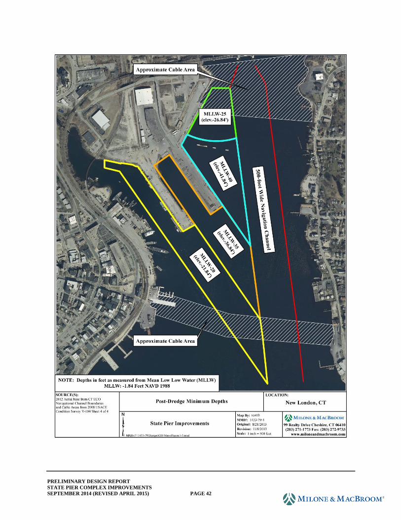
PRELIMINARY DESIGN REPORT
STATE PIER COMPLEX IMPROVEMENTS
SEPTEMBER 2014 (REVISED APRIL 2015) PAGE 42
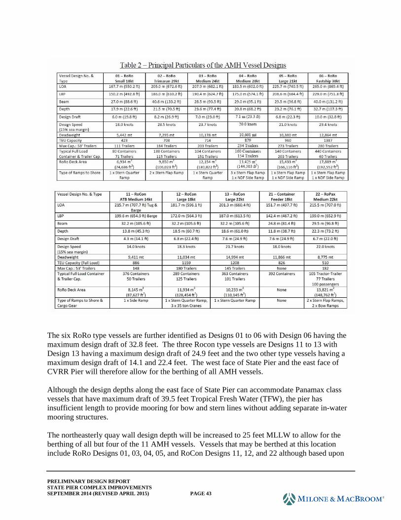
PRELIMINARY DESIGN REPORT
STATE PIER COMPLEX IMPROVEMENTS
SEPTEMBER 2014 (REVISED APRIL 2015) PAGE 43
The six RoRo type vessels are further identified as Designs 01 to 06 with Design 06 having the
maximum design draft of 32.8 feet. The three Rocon type vessels are Designs 11 to 13 with
Design 13 having a maximum design draft of 24.9 feet and the two other type vessels having a
maximum design draft of 14.1 and 22.4 feet. The west face of State Pier and the east face of
CVRR Pier will therefore allow for the berthing of all AMH vessels.
Although the design depths along the east face of State Pier can accommodate Panamax class
vessels that have maximum draft of 39.5 feet Tropical Fresh Water (TFW), the pier has
insufficient length to provide mooring for bow and stern lines without adding separate in-water
mooring structures.
The northeasterly quay wall design depth will be increased to 25 feet MLLW to allow for the
berthing of all but four of the 11 AMH vessels. Vessels that may be berthed at this location
include RoRo Designs 01, 03, 04, 05, and RoCon Designs 11, 12, and 22 although based upon
PRELIMINARY DESIGN REPORT
STATE PIER COMPLEX IMPROVEMENTS
SEPTEMBER 2014 (REVISED APRIL 2015) PAGE 44
the configuration and length of the quay wall these vessels may be limited to the use of stern
ramps for loading and offloading.
All other smaller vessels and barges will continue to be able to utilize the northwest quay and the
western face of CVRR Pier for berthing space.
Although the federal channel and approaches are wide enough for vessels to utilize the water
sheet east of the facility for a turning basin, additional depth will be provided to the east of State
Pier, along with the removal of the existing (former Navy) dolphins and mooring platforms to
enable increased maneuvering area for vessels approaching the east berthing area alongside State
Pier and the northeasterly quay wall. Much of this area is already at or near the targeted dredge
depth.
Dredging of these areas is estimated to ultimately result in the generation of approximately
485,000 cubic yards of improvement material. The management location of the improvement
material has not yet been determined. Additional testing of the sediment and coordination with
the USACE are required to identify the management location. On October 10, 2013, the design
team met with CTDOT Facilities and Environmental Compliance staff to discuss dredging and
disposal options. It was agreed that CTDOT should pursue additional testing during the
preliminary engineering phase to better characterize sediment/dredge materials for design
purposes. Meetings and discussions with CTDOT served to define the desired testing program;
however, CTDOT has elected to defer sediment sampling to a later date. Hence, the preliminary
design does not incorporate the previously anticipated supplemental testing results for inclusion
in the plans, as referenced under Items 4.1.3 and 4.2.2 in the scope. At this time, disposal
options include but are not necessarily limited to upland disposal and beneficial reuse, off-shore
open water disposal, and/or off-shore disposal in confined aquatic disposal cells. During final
design, we would anticipate CTDOT's testing program to furnish additional data with regard to
sediment characterization so that a preferred disposal option can be confirmed with the
environmental regulatory agencies.
Coordination with the USACE and the DEEP is required to identify the ultimate management
location. The following paragraphs describe the various alternatives for dredge disposal.
1. Open-Water Disposal
Previous studies have included the sampling of sediment immediately adjacent to the
eastern face of State Pier and to limited depths. These studies concluded that the material
designated for removal in this area contained a number of anthropogenic contaminants,
the most significant of which was determined to be Cobalt-60. The presence of Cobalt-
60 was attributed to the past berthing of U.S. Navy vessels, specifically submarines,
alongside the east side of State Pier.
The USACE, by way of a memorandum dated April 13, 2011, indicated that the
improvement material, as then contemplated and consisting of approximately 35,000
cubic yards of material, would not be suitable for open-water disposal within the Central
PRELIMINARY DESIGN REPORT
STATE PIER COMPLEX IMPROVEMENTS
SEPTEMBER 2014 (REVISED APRIL 2015) PAGE 45
Long Island Sound (CLIS) disposal area. The memorandum identifies alternatives to
open-water disposal including upland disposal or disposal in confined aquatic cells.
In a March 14, 2014 email, CTDOT's Office of Environmental Compliance
acknowledged the cost of biological testing required to further explore open-water
disposal as an alternative and recommended that due to technical and regulatory obstacles
this disposal option not be pursued any further.
2. Upland Disposal and Beneficial Reuse
The State of Connecticut regulates marine dredge material as a "special waste" and, as
such, any reuse of the material must be done with prior approval by the DEEP. Typical
options include disposal at a landfill or reuse as a beneficial material (i.e., cover material)
at a landfill or at another location with the approval of the DEEP. The presence of
Cobalt-60 is likely to present an impediment to beneficial reuse approval. Landfill
disposal options within the State of Connecticut are limited due to the closed status of
many local landfills. Options beyond Connecticut are more numerous but require greater
material transportation expenses.
3. Waterfront Development
The possibility of creating additional upland terminal area at the State Pier facility has
been previously discussed. The primary area for reuse of the material would be in the
apron area located between State Pier and CVRR Pier. This option would require the
construction of a bulkhead waterward of the intertidal lands and then placing the dredge
material to the landward side of the bulkhead. After filling, drying, and consolidation,
the created land would then be adapted for use as additional terminal space.
The use of material as described above would result in the permanent displacement of the
intertidal habit located along the waterfront. With this disposal option, the available
volume for the dredge material is minimal compared to the overall proposed dredge
volume.
4. On-site Fill Material
Another beneficial use of the dredge material includes dewatering of the material and
subsequent use as fill material at the State Pier facility. The material could be amended
with a sufficient quantity of sand or gravel to allow for its use as geotechnical suitable
fill. This option however is not considered feasible as other evaluations of the port
facility suggest that the upland area improvements will require the net removal of
material.
PRELIMINARY DESIGN REPORT
STATE PIER COMPLEX IMPROVEMENTS
SEPTEMBER 2014 (REVISED APRIL 2015) PAGE 46
5. Confined Aquatic Cell Disposal
The USACE has identified Confined Aquatic Disposal (CAD) Cells as an option for
disposal of the dredge material. CAD cells may need to be constructed at an approved
location as part of the improvement dredging project. The original material is taken to an
approved off-shore facility or reused for beneficial uses if appropriate. The cell or cells
would need to be large enough to accommodate the anticipated volume of improvement
material, and a suitable volume of borrow material would need to be identified and
transported to the CAD cell location to use as a cover material.
4.6 Freight Rail
4.6.1 Planned Improvements (See Freight Rail plans.)
In conjunction with reconfiguration of the waterfront structures to better accommodate marine
traffic, it is also necessary to reconfigure the roadways and rail trackage serving CVRR Pier.
Any changes to the number and location of tracks supporting marine activities at CVRR Pier
along with changes to the NECR support yard should be accomplished to:
Improve the movement of marine traffic to and from the piers
Improve the movement of rail traffic to and from the piers
Provide an upgraded rail support yard that expedites the handling of inbound and
outbound trains
Provide an upgraded rail support yard that expedites the movement of freight to and from
the piers
Provide the ability to handle different types of rail cars (double stack), if possible, so as to
accommodate new types of business to and from destinations on Class 1 carriers, which
are currently unserved from the Port of New London
Provide enhanced connectivity for and between the various transportation modes
Any planned improvements should use practices and materials currently recommended by the
American Railway Engineering and Maintenance-of-Way Association (AREMA) and accepted
by the rail industry in North America so as to:
Ensure compatibility of plant and equipment
Provide uniformity of materials for both construction and maintenance
Provide longest useful life possible
Provide low operating and maintenance costs
Long term, the state might consider incorporating a rail barge loading dock for rail cars adjoining
the CVRR pier; the design is not to preclude future construction of such. While such an
investment should be justified based on demand, the design should consider any future plans for
such so as not to preclude construction at a later date.
PRELIMINARY DESIGN REPORT
STATE PIER COMPLEX IMPROVEMENTS
SEPTEMBER 2014 (REVISED APRIL 2015) PAGE 47
4.6.2 Requirements and Constraints
While the piers are to be reconfigured to better accommodate marine cargo flow, there will be a
number of constraints that need to be addressed when developing new rail connections to the
piers. Most of the constraints are geometric in that rail cars and trains cannot easily navigate
steep grades and low radius curves as can trucks and other highway vehicles. The design intent
is to maintain the existing track on State Pier and to restore the track on CVRR Pier with a new
single track laid down the center of the pier. While historically CVRR Pier was served by on-
dock rail, at present there are no tracks. The current plan calls for raising the pier surface to El.
8.0 at the center, thereby requiring adjustment of the vertical geometry for the track between the
pier and NECR parcel for up to 2.0 feet over a relatively short distance overall. Revising track
elevations does present some challenges.
For example, if double-stack domestic containers are desired to be used and must be spotted on
the piers for direct loading by crane, then vertical (overhead) clearances under the NEC and local
roadways must be increased to 20' – 6". This will require an additional 8" of clearance at State
Pier Road and Amtrak.
Additionally, given sea elevation rise and more frequent major storms, the railroad will
potentially experience more flooding and be out of service intermittently.
Vertical and horizontal geometrics will play a significant role in determining what railroad
alignments are possible when accessing newly designed and renovated piers. During the course
of preliminary design, the consultant requested approval for extra work to obtain survey on the
NECR parcel in an effort to determine existing track location and elevation. This work was not
advanced as a preliminary design task; however, the additional survey will be needed in order to
complete final design. The proposed rail plans indicate a new track on CVRR Pier at El. 8.0 feet,
and a horizontal alignment is based on best available mapping. It is unclear at this time as to
how well the track alignment and grade meet with the existing track on NECR's parcel.
It should be noted that the design for track on CVRR Pier will necessitate the need for piles to
support the design loads. Due to issues of continuing settlement at the pier, the structural design
incorporates piles to support the rail without having to rely on the soil fill.
4.7 Site Security
Port security at present is the responsibility of the facility operator, currently Logistec. A
security plan meeting Maritime Transportation Security Act (MTSA) requirements is in place.
Recent security measures implemented include new fencing and gates, increased site lighting,
and a web-based video camera surveillance system. The Port Master Plan indicates the eventual
handling of container cargo thereby requiring security upgrades to comply with U.S. Customs
requirements.
PRELIMINARY DESIGN REPORT
STATE PIER COMPLEX IMPROVEMENTS
SEPTEMBER 2014 (REVISED APRIL 2015) PAGE 48
Proposed port security enhancements include a new
entrance/exit gate that meets U.S. Customs measures and
designation as a Part 105 facility. Refer to the illustration
entitled "Part 105 Site Security and Access" on the
following page.
Under the proposed plan, State Pier Road, which is a public
roadway, will be terminated at a cul-de-sac east of the
current entrance roadway. The cul-de-sac will provide
temporary access to the Amtrak bridge tender parking, as
well as the state-owned public boat launch until such time as it may be relocated. Exclusion
gates and fencing will secure the perimeter of the terminal entrance. A new administration
building and guard house adjoin the entry facility and will house security personnel and
monitoring and gate control equipment. Parking will be provided outside the Part 105 facility
perimeter. Lighting of the site north of State Pier Road will need to be addressed as usage
warrants, but design of such has not been included in the preliminary design. The plans indicate
segments of existing fencing to remain, as well as fencing to be replaced. Proposed gates are
also shown. It is assumed the gates will be reinforced to resist intrusion by impact. Refer to
Section 2.2 Site Access and Upland Facilities, Paragraph 2.2.1 Roadways, herein, for discussion
on Thomas Griffin Boulevard as a point of access for emergency access. The plans indicate
minimal improvements for paving and fencing at this location in order to maintain this additional
physical connection to the local roadway network.
A canopied gate plaza will contain an exclusive entrance lane and exit lane, a reversible lane, and
a bypass lane for facility staff. Provision for Radiation Portal Scan (RPS) units, a VACIS unit
(Vehicle and Cargo Inspection System), cameras, and ticket processing equipment including
utility connections will also be made. The RPS units may be contained within (or just interior to)
the canopied gate plaza. These units will screen outgoing trucks for contents that may contain
radioactive materials. If radiation is detected, the vehicle may then be isolated and its contents
scanned by use of a VACIS unit with gamma-ray imaging capability. The unit may be
portable/mobile or permanent/stationary. Should the cargo/vehicle contents be in question, the
truck may remain isolated and its contents emptied for further inspection. For this, a fenced
Customs inspection area with a minimum 320-square-foot platform is provided for unloading. A
ramp is provided in the design for fork lift access to the platform.
Permanent VACIS Unit
Mobile VACIS Unit
RPS Unit
PRELIMINARY DESIGN REPORT
STATE PIER COMPLEX IMPROVEMENTS
SEPTEMBER 2014 (REVISED APRIL 2015) PAGE 49
PRELIMINARY DESIGN REPORT
STATE PIER COMPLEX IMPROVEMENTS
SEPTEMBER 2014 (REVISED APRIL 2015) PAGE 50
5.0 PERMITS AND APPROVALS
5.1 Jurisdictional Boundaries and Permits Required
On July 11, 2013, Milone & MacBroom, Inc. visited the State Pier complex and delineated
wetland jurisdictional boundaries in accordance with the Connecticut Tidal Wetlands Act. This
boundary is depicted on the existing conditions site map. Tidal wetlands are defined by the
presence of certain plants as named in the statute. These plants are dependent upon and tolerant
of regular tidal inundation. Tidal wetlands were found (intermittently) to the west of the piers,
beginning at the railroad bridge over the Thames River, continuing around the state piers, and
then northward under the I-95 bridges. The presence of tidal wetlands at the site is not
continuous because there are no tidal plants growing on bulkheads, retaining walls, parking lots,
etc.
Several other wetland-related regulatory boundaries occur at the site, including various tidal
elevations (Mean High Water, Connecticut Coastal Jurisdiction Line, and others). The site is
also affected by regulatory flood zones such as the 100-year floodplain and FEMA regulated
floodway. The state's Stream Channel Encroachment Line has recently been eliminated as a
regulatory limit. The site is also within the coastal management zone, and development will be
regulated by the state through the Office of Long Island Sound Programs (OLISP).
The most recently adopted Flood Insurance Study (November, 2011) indicates the 100-year
flood elevation is 11.0' (NAVD88). It should be noted that both piers and all of the freight rail
track at the complex are situated below the 100-year flood elevation. While there is little
opportunity to raise the facilities above the floodplain, the CTDOT has confirmed its intent to
maintain the elevation of State Pier and to raise CVRR Pier as much as possible while
maintaining freight rail connectivity and not impacting passenger rail. The elevation associated
with the velocity zone is 13.0' per the current FEMA map.
Review agencies will include the CTDEEP (primarily through OLISP), USACE, U.S. Coast
Guard, FEMA, United States Department of Agriculture through Marine Fisheries, U.S. Fish and
Wildlife, U.S. Environmental Protection Agency, and possibly others.
The activities that will trigger the need for permits or approvals include:
Construction of structures, dredging, and placement of fill, within the various regulatory
limits referenced above (CGS: Sec. 22a-359 - 22a-363f)
Direct or indirect impacts to tidal wetlands (CGS Sec. 22a-28 - 22a-35)
Other permitting issues may be related to navigation, shellfish beds, threatened and
endangered species, marine fishery resources, and more.
Work in navigable waters
It should be noted the project plans call for installation of bulkheads, piles, fill, and other
materials waterward of existing structures and shoreline. In addition, the plans call for dredging,
PRELIMINARY DESIGN REPORT
STATE PIER COMPLEX IMPROVEMENTS
SEPTEMBER 2014 (REVISED APRIL 2015) PAGE 51
which may result in off-shore or in-water disposal. All of these activities would be regulated as
discussed herein.
On December 29, 2011, CTDOT issued an Environmental Review Form (ERF) for the State Pier
project. The following environmental and ecological issues are addressed in the ERF:
Section 3: Section 106 Review for Historical and Archaeological Resource issues. The 2011
ERF includes mapping of historic/archaeological sites in the vicinity of the State Pier project and
concludes that a referral to the State Historic Preservation Office (SHPO) was required. A
response from SHPO is needed for the project and may have already been obtained by CTDOT.
Section 4: Water resources and permits information is complete and still valid as detailed earlier
in this memo.
Section 5: Natural resources information is reviewed including the possible presence of "listed
species." This information is accurate and still valid. Peregrine falcon has nested on the
infrastructure of the Gold Star Bridge, and fishery resources are present in the Thames River.
Likely Regulated Permits
The following table summarizes the likely permits and anticipated permit schedule for the State
Pier project. As project design moves forward, the permits and schedule may be refined.
TABLE 5-1
Summary of Regulatory Permits and Schedule
Regulatory Agency Permit Type Regulatory Review and
Approval Schedule
USACE Individual Permit 6 months
CTDEEP OLISP Structures Dredging
and Fill
6-8 months
CTDEEP Flood Management Certificate 6 months
CTDEEP General Stormwater Permit 3 months
CTDEEP General Permit for
Stormwater Associated with
Commercial Activities
3 months
PRELIMINARY DESIGN REPORT
STATE PIER COMPLEX IMPROVEMENTS
SEPTEMBER 2014 (REVISED APRIL 2015) PAGE 52
Permitting Strategy
Given the number of projected regulated resource activities for the State Pier project, it is
recommended that the project be permitted as a single complete project from both a permitting
time line and project budget standpoint. After receiving the required permit approvals, the state
can then determine phasing of the proposed work. Funding sources for this project have not yet
been determined; however, a combination of federal and state funds is anticipated for this
project.
As the site plan development moves into semi-final design phases, it will become imperative to
obtain buy -in from the CTDEEP with regard to projected regulated resource impacts and the
need for mitigation for those permitted activities. Understanding the appropriate mitigation
requirements will allow CTDOT to evaluate potential mitigation sites on and/or near the project
site and help determine likely mitigation costs associated with implementing such mitigation
measures.
5.2 Stakeholder Coordination
As the design evolves, a stakeholder involvement program should be developed to identify
specific stakeholder concerns and end-user needs. The CTDOT should engage the affected
stakeholders early in order to minimize the potential for redesign later. At the time of
preparation of this report, the following stakeholder group has been identified:
Fishing fleet
DEEP Boat Launch
Amtrak
Logistec
Pilots
NECR
Thames River Seafood Cooperative
ILA Local 1411
City of New London
6.0 DESIGN PROCEDURES AND INPUT PARAMETERS
6.1 Project Datum and Horizontal Controls
Project vertical datum will be NAVD 88, and all elevations will be standardized to this datum.
For the purpose of standardizing structural elevations from previous designs, which were based
on NAD 27 horizontal datum and NGVD 29 vertical datum, the following conversion will be
used:
NAVD 88 = NGVD 29 elevation - 1.0 foot
Note that based on recent information provided by the USACE, the new dredge depth will be
based on depth from MLLW, which is now defined by the USACE as being -1.84 NAVD at the
project site.
PRELIMINARY DESIGN REPORT
STATE PIER COMPLEX IMPROVEMENTS
SEPTEMBER 2014 (REVISED APRIL 2015) PAGE 53
The project horizontal controls are established based on State of Connecticut planar coordinates,
which are based on NAD 83 (2011) (EPOCH:2010.0000). All project baselines will reference
State of Connecticut planar coordinates.
6.2 Wharf Structures and Waterfront Cargo Operations
The design provides the State Pier facility with almost 5,000 feet of deep-water wharfage in three
areas and another 345 feet of wharfage for shallower draft vessels. The entire waterfront area
will be designated for the loading and unloading of cargo.
6.3 Prop Wash and Scour
Mooring, berthing, and climactic loading studies were not included in the scope for this phase of
the project. These studies would have included prop wash and scour analysis. Based on existing
site information provided by the owner, it appears that soils within the proposed dredge line are
predominately sandy in nature. The State Pier West Rehabilitation drawings (2000) indicate
design nonoperational current to be two knots. It is not expected that this would induce a
controlling design consideration for the deeper depths that have been discussed and will be
neglected for this preliminary engineering and design effort.
However, prop wash (such as from bow thrusters or a nearby tug) can cause significant localized
scour in sandy soils, depending on the structure type and distance from the structure. Should the
project advance beyond this current phase, it is recommended that a study be performed to
determine the likelihood of prop-induced scour effects and to perform the analysis necessary to
predict those effects, if appropriate.
For the purpose of this phase, where recommended bulkhead structures could be prone to wash,
the design team will perform a relative analysis for the proposed design dredge depth (with
overdredge) and for the design dredge plus six feet of additional wash scour to verify structure
stability for both conditions and to provide some sensitivity comparison for potential costs
associated with scour protection, or structure modification, should this be a controlling design
scenario. Appropriate factors of safety for both conditions are discussed in Section 7.6. Note
that actual depth of localized thruster induced scour is highly dependent on actual thruster power,
soil conditions, and distance from the structure. Verification of actual predicted depth should be
performed during detailed design if expected vessel operations necessitate doing so.
6.4 Design Dredged Depth
The design dredge depth is based upon the design specifications of AMH vessels. Vessels
meeting the AHM specifications will berth at both sides of State Pier, along the eastern side of
CVRR Pier, and along the northeast quay wall. The northwest quay wall and the western side of
CVRR Pier would be reserved for smaller vessels and barges. More details concerning the
design input parameters for the improvement dredging are included in Section 4.3.
PRELIMINARY DESIGN REPORT
STATE PIER COMPLEX IMPROVEMENTS
SEPTEMBER 2014 (REVISED APRIL 2015) PAGE 54
6.5 Soil Parameters
Soil design parameters are based on the results of laboratory testing of field-collected data (for
quantitative purposes of describing engineering properties) and on consideration of previous
exploration activities and findings (for qualitative purposes only). Soil design considerations
will be fully briefed in a separate deliverable to be prepared by Mueser Rutledge as part of this
project and will include recommendations for pile installation methods and capacity, settlement
(for fill areas), compaction methods, and other considerations as required. The required analysis
is based on design input regarding the approved structure alternate and installation methods and
therefore has been developed in tandem with the preliminary design. Additional geotechnical
data obtained to date is included in Appendix B. Preliminary structure and roadway soil reports
have been prepared and are submitted as separate reports with the Preliminary Design
Submission.
6.6 Wharf and Quay Bulkhead Design Methodology
Sheet Pile Bulkhead Design Methodology
The design of bulkhead structures will be in accordance with the USACE Engineering Manual
1110-2-2504 "Design of Sheet Pile Walls." Modifications, assumptions, and criteria are as
follows:
Stability Analysis: Classical methods for free earth condition will be used for determining
minimum tip embedment, using factored soils and the Coulomb earth pressure model. For
determining tip embedment, ultimate passive soil parameters will be reduced by a factor of
safety in the performance of stability calculations. For this project, stability calculations
will consider soil reductions for FS = 1.5, where tan(F')=tan(F)/FS, and c'=c/FS. For the
sensitivity analysis for thrust-induced localized scour, FS on embedment may be taken as
1.2 for nonfactored soils. For earthquake analysis, stability will be based on nonfactored
soils, where active side soil effective density is increased by percentage equal to the site
acceleration (in g's), and passive side soil effective density is decreased by percentage equal
to the site acceleration (method described by USACE program, CWALSHT user manual).
For preliminary design, acceleration will be taken as 0.15g, per State Pier east and west side
reconstruction drawings. Minimum factor of safety on embedment will be 1.1 for the
earthquake condition.
Structural Analysis: Structural analysis for sheet pile and tie rods will be based on
reanalyzing the system with nonfactored soils (i.e., FS=1.0). Sheet pile design will be based
on free earth condition. For preliminary and conceptual designs, this analysis is typically
based on classical methods, using CWALSHT or similar software, which typically provide
conservative structural performance predictions for typical solutions. However, at the
consultant's discretion should the structure type or preliminary findings indicate it to be
warranted, finite element soil structure interaction software may be employed such as PY-
Wall (Ensoft) or other suitable structural design suite, which allows for input of nonlinear
soil springs.
PRELIMINARY DESIGN REPORT
STATE PIER COMPLEX IMPROVEMENTS
SEPTEMBER 2014 (REVISED APRIL 2015) PAGE 55
It assumed that all sheet piling will be coated full height on water side (and land side within
the oxygenation zone), or be concrete encapsulated within the oxygenation zone. Therefore,
analysis will be based on an assumption of 25 years of corrosion loss, in the zone between
mudline and encapsulation, at a rate of 5 mils per year, water side only.
Anchor Wall Stability: Anchor walls will be analyzed to determine theoretical factor of
safety based on predicted service loads (nonfactored soils) and available net passive
resistance, in accordance with equations (5-8) and (5-9) of EM 1110-2-2504. The anchor
wall will be designed to develop the yield strength of the anchor rod. Anchor walls will be
analyzed based on assumption of area live load applied only on the landward side of the
structure.
Grouted anchors, if utilized, will be grouted outside of the active wedge, in competent
material, and will develop the full yield capacity of the bar. All ties will be field proof
loaded to 110% of the nominal design load, and a minimum of 2% will be tested to 150% of
the design load capacity.
Allowable stresses per combined axial and bending, AISC:
o Flexural design: fb ≤ 0.60 Fy for the dredge plus scour condition. Where combination
sections are considered, the stress will be determined, on a per foot basis, by computing
the composite section modulus of a structural unit, divided by the width of that unit. A
33% overstress allowance will be considered for the earthquake condition.
o Tie rod design: ft < 0.6 Fy or 0.50 Fu (whichever controls) with a 33% overstress
allowance for the earthquake condition.
o Anchor wall design: Anchor wall structures will be designed for Fb ≤ 0.6 Fy at tie rod
yield.
Design Software:
o CWALSHT
o CASE/GCASE Program, Program #: x0031; 1996
o L-pile Plus; V. 5.0.31; Ensoft Inc.; 2007
o PY Wall (latest)
o SAP 2000
o RISA 3D v9.1
Bulkhead top elevation: +7.0' NAVD88 (nominal, may be dependent on geometrical
restrictions specific to the alternative under consideration)
Bulkhead fill elevation: +7.0' NAVD88 with an allowance for pavement and base
overburden to elevation +8.5 NAVD88
PRELIMINARY DESIGN REPORT
STATE PIER COMPLEX IMPROVEMENTS
SEPTEMBER 2014 (REVISED APRIL 2015) PAGE 56
Bulkhead surcharge: Area live load or equipment live load, as controls, per loads specified
in Section 8.0 of this document. Area live load will be applied extending from bulkhead to
a distance of 100 feet landward of the waterside rail.
Bulkhead anchor elevation: Varies per structure.
6.7 Framed Wharf Structures Design Methodology
Framed structures, such as pile-supported platforms and relieving platforms, will be designed in
accordance with most recent AISC and ACI requirements. Steel may be designed using either
Load and Resistance Factor Design (LRFD) or ASD methods, provided all elements in the given
structure are designed to the same method. Concrete structures will be designed based on LRFD.
As applicable, allowable stresses and serviceability requirements will be modified for the
marine-specific environment, as recommended by USACE (see EM 1110-2-2104 & 2105).
Determination of structural response and stresses shall consider stiffness matrix or finite element,
if applicable, to optimize designs or to assess complex conditions. Applicability will be
determined by the design team, on a case-by-case basis, specific to the complexity of the
structure being analyzed. Secondary stresses, such as those induced by temperature, shrinkage,
and deflection induced moments will be considered as applicable.
Soil founding elements will be designed in accordance with recommended parameters to be
provided by Mueser Rutledge as part of this project. Allowable capacities will be based on a
safety factor (typically ranging from 1.5 to 3.0) that is reflective of the loading considered
(tensile or compressive) and the level of installation testing that is performed to ground truth
conditions. Factors will be determined and assigned during Phase 2, Detailed Design.
Steel pipe pile section losses will be considered between mudline and encapsulation, similar to
that described in paragraph 6.6. In addition, it is assumed that losses uniformly affect the
circumference of the pile.
Design Software:
o SAP 2000
o RISA 3D v9.1
o CASE/GCASE Program, Program #: x0031; 1996
o L-pile Plus; V. 5.0.31; Ensoft Inc.; 2007
6.8 Freight Rail Design Methodology
CVRR Pier will be reconstructed to better handle marine traffic, and track is to be restored on the
pier. Chapter 4.0 Functional and Operational Planned Improvements, Section 4.4 Freight Rail,
herein, provides more background information with regard to track at the CVRR Pier. The
proposed project will base the new rail design leading to and at the CVRR Pier on several criteria
to include:
PRELIMINARY DESIGN REPORT
STATE PIER COMPLEX IMPROVEMENTS
SEPTEMBER 2014 (REVISED APRIL 2015) PAGE 57
American Railway Engineering and Maintenance (AREMA) recommended practices
NECR track and industrial track design criteria
Best Practices from the Seven (7) Major Class 1 Railroads in North America
It is expected that there will be two types of track construction used in the project to include:
Ballasted track construction in the NECR flat yard and tracks approaching the piers
Embedded track construction at piers where the rails are in the pavement and/or deck
Some of the input parameters that will be used in the design of the track structure are listed
below:
Types of rail equipment to be used:
Length, height, and width
Required clearances
Gross vehicle weights
Horizontal alignment:
Degree curve (maximum allowed)
Length of curve
Curve elevation
Length of spirals (if required)
Vertical alignment:
Grade (maximum allowed)
Difference in grade (maximum allowed)
Length of vertical tangents (minimum allowed)
Typical Details:
Ballasted track cross section
Rail
Ties
OTM (plates, spikes, and anchors)
Ballast
Subballast
Drainage
Embedded track cross section
Rail
Flangeways
Ties
OTM (plates, spikes, and anchors)
Ballast
Subballast
Drainage
Pavement Design
PRELIMINARY DESIGN REPORT
STATE PIER COMPLEX IMPROVEMENTS
SEPTEMBER 2014 (REVISED APRIL 2015) PAGE 58
Grade crossing cross section
Rail
Flangeways
Ties
OTM (plates, spikes, and anchors)
Ballast
Subballast
Drainage
Pavement Design
Pavement Markings
Signage
Turnouts
Size
Type
Rail weight
Bolted or welded
7.0 DESIGN LOADS AND LOADING COMBINATIONS
7.1 Wharf and Yard Live Loading
7.1.1 Design Vessel Parameters for Each Structure
Northwest Quay - Stone Bulkhead
The Northeast Quay wall will be designated for the local fishing fleet. The entire length will
have a bulkhead installed waterward from the existing stone masonry wall that is in poor
condition. The area will also be dredged to El. -18.0. New electrical lines will be run along the
apron for possible use by the fishing fleet. The area could also be used for material storage if the
fishing fleet does not relocate.
CVRR Pier (Long Dock)
The CVRR Pier east berth will be designed to accommodate the same design vessels as the State
Pier (described below) as well as AMH RoRo vessels. The west berth will be designed for barge
docking.
Center Shoreline and Pile-Supported Wharf Platform
The existing pile-supported wharf will be demolished, and the center shoreline segment will be
reconstructed to provide a regular interface at the waterfront and to remediate the existing block
retaining wall. Because of its location, the structure will not serve as a vessel berth. The wharf
will be designed for the designated cargo area stacking and storage loads and for passing heavy
lift equipment, which are identified in Section 8.0.
PRELIMINARY DESIGN REPORT
STATE PIER COMPLEX IMPROVEMENTS
SEPTEMBER 2014 (REVISED APRIL 2015) PAGE 59
Admiral Shear State Pier
Ports staff have indicated that vessel size and type are not expected to vary from those that were
considered for the design of the east and west State Pier rehabilitation projects (1995 and 2000,
respectively) and have advised that any proposed modification or improvements to this structure
shall be designed to the same standard. In summary, the vessel-related design parameters for this
structure are as follows:
Maximum fully loaded vessel:
o Displacement: 29,000 long tons
o Length Overall: 570-ft
o Beam: 80-ft
o Overall Depth: 43-ft
o Maximum Draft: 31-ft
Maximum partially loaded vessel:
o Displacement: 54,000 long tons
o Length Overall: 800-ft
o Beam: 120-ft
o Overall Depth: 70-ft
o Maximum Draft: 31-ft
Barge 180-ft x 50-ft x 17-ft (South End Only)
o Displacement: 2,400 long tons
o DWT: 1,800 long tons
o Draft: 12-ft
Coaster 200-ft x 35-feet x 18 feet (South End Only):
o Displacement: 1,800 long tons
o DWT: 1,200 long tons
o Draft: 15-ft
o Maximum Draft: 31-ft
Ocean tug 125-feet x 36-feet x 19 feet (South End Only):
o Displacement: 1,400 long tons
Northeast and Northeast Timber Pile-Supported Wharf Platform
The existing pile-supported wharf will be demolished, and this segment will be bulkheaded and
filled to provide a regular interface at the waterfront and to remediate existing block retaining
wall. The structure will be connected to the adjacent bulkhead structure to the east and will have
an expansion joint between the State Pier and the Northeast structure but provide a uniform
berthing face. This structure will be designed to accommodate AMH RoRo vessels, coastal
feeder vessels, tugs, and barges.
7.1.2 Structural Deck Loads
Ports staff have indicated that expected vessel size and type are not expected to vary from those
that were considered for the design of the east and west State Pier rehabilitation projects (1995
and 2000, respectively) and have advised that any proposed modification or improvements to this
PRELIMINARY DESIGN REPORT
STATE PIER COMPLEX IMPROVEMENTS
SEPTEMBER 2014 (REVISED APRIL 2015) PAGE 60
structure shall be designed to the same standard. In summary, the structural deck loads are as
follows:
Uniform Live load: 1,000 PSF
Truck: AASHTO HS-20
Forklift Truck: Axle Load with 36 Ton load payload: 215 kips maximum on four tires
Crawler Crane: (Manitowoc 4100W Series 2 or equal)
o Payload: 50 tons at 50 foot radius
o Payload: 36 tons at 65 foot radius
o Payload: 20 tons at 100 foot radius
o Dimensions
45 inch minimum contact width (flattened crawler pad)
18'-7" minimum contact length
Impact on structural deck, beams, and pile caps: 15% for rubber tire vehicles and moving
crawler crane
7.1.3 Storage Areas
Based on the possible cargo types projected to be handled at the State Pier Complex, from
stacked containers to bulk material, a uniform loading of 2,000 pounds per square foot is
proposed for all storage areas. The storage areas will be paved with bituminous concrete
materials.
7.1.4 Designated Roads
State Pier Road is the only roadway that will be modified, and it will be designed to carry
normal American Association of State Highway and Transportation Officials (AASHTO) truck
loads. Access roads within the complex will be constructed to the same capacity as the storage
areas.
7.1.5 Freight Rail
If and when the piers are reconfigured to better handle marine traffic, there may be a need to
reconfigure existing trackage. HDR will base the new rail design loads to and at the piers on
several criteria to include:
American Railway Engineering and Maintenance (AREMA) Recommended Practices
NECR Track and Industrial Track design Criteria
Best Practices from the Seven (7) Major Class 1 Railroads in North America
Special Requirements from the Port of New London
State Legal Requirements
It is expected that there will be two types of track construction used in the project to include:
PRELIMINARY DESIGN REPORT
STATE PIER COMPLEX IMPROVEMENTS
SEPTEMBER 2014 (REVISED APRIL 2015) PAGE 61
Ballasted Track Construction in the NECR flat yard and tracks approaching the piers
Embedded Track Construction at piers where the rails are in the pavement and/or deck
Design loading and clearances are especially important to the operability and long-term
performance of the track structure. HDR will review with the Project Team, Port of New
London, and NECR both existing and proposed loads and clearances required.
At this time, it is expected that at least the following minimums will be required:
Gross Rail Car loads: 286,000 lbs.
Required Plate Clearances: Plate "F"
7.1.6 Mooring and Breasting Loads
Northwest Quay – Stone Bulkhead (If new structure installed)
This area is intended to be used by the local fishing fleet. Fenders, cleats, and bollards as
currently exist on the west side of CVRR Pier will be relocated to this area.
CVRR Pier (Long Dock)
A mooring analysis for this structure was not included in the scope of work. It is assumed that
vessel traffic will remain shallow draft barge or smaller cargo feeder vessels. The following
loads, to be combined to generate controlling effect, will be used in the conceptual structural
design. The required bollard will be 100-ton capacity.
Lateral Load Parallel to the face of the wharf: 100 kips
Lateral Load Perpendicular to the face of the wharf: 100 kips
Uplift: 50 kips
A breasting analysis for this structure was not included in the scope of work. For the purpose of
this conceptual design, the structure will conservatively be designed for similar fender
absorption/reaction as the Admiral Shear State Pier, as this is typically not a controlling loading
scenario for bulkhead structures and will allow for similar components for maintenance.
Typical Units (east and west face) (assume 34-ft max spacing):
o Min. Energy Absorbed per Assembly: 162 Ft-Kip.
o Max. Reaction per Assembly: 134 Kip.
End Units:
o Timber piles / framing / bracing; steel waler; piles at maximum 9-ft spacing.
o Rubber Element Units (upper and lower, at 9-ft maximum spacing):
Min. Energy Absorbed per each: 46 Ft-Kip.
Maximum Reaction per each: 50 Kip.
Corner Units
o Min. Energy Absorbed per Assembly 244 Ft-Kip
o Max. Reaction per Assembly: 202 Kip.
PRELIMINARY DESIGN REPORT
STATE PIER COMPLEX IMPROVEMENTS
SEPTEMBER 2014 (REVISED APRIL 2015) PAGE 62
Center Shoreline and Pile-Supported Wharf Platform Replacement Bulkhead (Central Wharf)
The primary vessel working areas are the alongside berths on the east or west face of each finger
pier. Due to the geometrical constraints of the basin (the close proximity of the two finger piers),
it is not anticipated that this region will be utilized for vessel berthing, and no loads have been
established. Fenders, cleats, and bollards are not to be installed in this area.
Admiral Shear State Pier
A mooring analysis for this structure was not included in the scope of work. All mooring and
breasting loads are based on the design parameters given in the 2000 West Pier rehabilitation
drawings.
Mooring Loads:
o Mooring loads were not given in the drawings; however, 100-ton bollards were
installed. Therefore, assume similar to those assumed for CVVR Pier:
Lateral Load Parallel to the face of the wharf: 100 kips
Lateral Load Perpendicular to the face of the wharf: 100 kips
Uplift: 50 kips
Fenders / Fender Loading:
o Typical Units (east and west face) (assume 34-ft max spacing):
Min. Energy Absorbed per Assembly: 162 Ft-Kip.
Max. Reaction per Assembly: 134 Kip.
o End Units:
Timber piles / framing / bracing; steel waler; piles at maximum 9-ft
spacing.
Rubber Element Units (upper and lower, at 9-ft maximum spacing):
Min. Energy Absorbed per each: 46 Ft-Kip.
Maximum Reaction per each: 50 Kip.
o Corner Units
Min. Energy Absorbed per Assembly 244 Ft-Kip
Max. Reaction per Assembly: 202 Kip.
Northeast Pile-Supported Wharf Platform Replacement Bulkhead and Northeast Quay Steel
Sheeting Bulkhead
This area is intended to be used by AMH RoRo vessels, coastal feeders, and barges. Fenders,
cleats, and bollards will be installed in this area.
7.1.7 Environmental Loads (delta T, wind, ice, current)
No metocean study or verification was included in the scope of work. Where applicable, criteria
have been adopted from the 2000 West Pier Rehabilitation drawings. The following criteria will
be used for design:
(i) Design Wind Speed: 84 MPH, no ship in berth; 45 MPH, ship in berth.
(ii) Wind Velocity on Vessels - was not considered for this scope.
PRELIMINARY DESIGN REPORT
STATE PIER COMPLEX IMPROVEMENTS
SEPTEMBER 2014 (REVISED APRIL 2015) PAGE 63
(iii) Currents – 2 knots, no ship in berth; 0.7 knots, ship in berth.
(iv) Temperature – Structures will be evaluated based on an assumed temperature variation in
service.
(v) Ice Loading: Sheet ice is not anticipated at this location, but pieces of ice floating
downstream in spring will be considered in the design.
(vi) Design Tide Elevations:
1. Extreme High Water: +8.91 NAVD 88
2. Extreme Low Water: -5.67 NAVD 88
(vii) Flood Elevation - Federal Emergency Management Agency (FEMA) 100-year flood
elevation shall be used. From published data, the 100-year estimated flood rises to El.
11.0.
(viii) Seismic Loads: A=0.15 (from 2000 West Pier Rehabilitation drawings)
7.1.8 Load Combinations
For determination of maximum member stresses, computed forces for various elements will be
applied in accordance with the following table.
DL
UL
L
EQUI
P HS
MOO
R FRN FRL BHAF H
T, W,
Ice
Current
Bulkhead Cap
Case 1 1.2 1.6 1.6 1.6 1.6
Case 2 1.2 1.6 1.6 1.6 1.6
Case 3 1.2 1.6 1.6 1.6 1.6 1.6
Bulkhead Anchor System3
Case 1 0.9 1.6 1.6 1.6 1.6
Case 2 1.2 1.6 1.6 1.6 1.6 1.6
Case 3 1.2 1.6 1.6 1.6 1.6 1.6
Case 4 1.2 1.6 1.6 1.6 1.6 1.6
Pile-Supported Structures4
Case 1 0.9 1.6 1.6
Case 2 0.9 1.6 1.6 0.9 1.6
Case 3 1.2 1.6 1.6 1.6
Case 4 1.2 1.6 1.6 1.6 0.9 1.6
Case 5 1.2 1.6 1.6 1.6
Case 6 1.2 1.6 1.6 1.6 0.9 1.6
Notes:
1.
Moving Moving loads shall include additional factors for impact, as required by applicable design codes.
2. Refer to Appendices for equipment load details.
PRELIMINARY DESIGN REPORT
STATE PIER COMPLEX IMPROVEMENTS
SEPTEMBER 2014 (REVISED APRIL 2015) PAGE 64
3. If using Allowable Stress Design for the steel members, the load factors shall be changed
to 1.0 for all load cases except for the "DL" component of Case 1 for Bulkhead Anchor
System which shall change to 0.6. For the extreme load conditions like mooring loads,
the allowable stresses may be increased by a factor of 4/3.
4. All wearing surfaces shall include allowance for future overlay for load cases 3 through 6.
Assume 1½-inch asphalt concrete overlay.
5. Apply equipment impact factors in accordance with governing design code where truck
traffic or operating equipment is considered.
For preliminary design, bulkhead components and existing pipe piles were checked for
seismic condition for combination of DL, ULL, and seismically influenced static earth or
static equivalent structure loading at increased allowable stress (see paragraph 6.7).
Abbreviations:
DL Dead Load (self weight) of structure being designed
ULL Uniformly distributed Live Load
EQUIP Equipment Loads
HS
AASHTO HS20 or HS25-44 designated loading criteria,
depending on structure
MOOR Mooring load from ship mooring analysis
FRN Fender reaction, normal to face of structure
FRL Fender reaction, parallel to face of structure
BHAF Bulkhead Anchor Force
H Load due to lateral earth pressure
8.0 PROJECT PHASING (SEE CONSTRUCTION PHASING PLAN.)
The State Pier facility must remain in service during the construction of the proposed
improvements. Because funding for the proposed improvements may not be available for the
complete project, work may be phased over multiple projects, perhaps over a number of years.
Phasing the work may result in added cost due to number of mobilizations, inflation, etc. Such
cost factors are difficult to ascertain at this point but may be refined as final design progresses
and construction activities are prioritized.
Regardless of timing, there are several drivers that dictate phasing. First, it will be necessary to
maintain port operations throughout construction, especially on State Pier, where the largest
vessels are permitted to berth. The need to maintain operations at the pier will require that
construction be limited to one side at a time. Given that the deepest water is on the easterly or
upstream side of State Pier, work may proceed on the west or downstream side first so that the
area can be dredged in order to accommodate those vessels that would normally berth on the east
side and which will be temporarily displaced during construction. Further, it may be necessary
to perform work from barge unless construction activities can be performed along the edge of
pier while maintaining sufficient space for operation of the opposite side of the pier.
Second, both piers must be stabilized prior to dredging. At State Pier, we understand that
material supporting the filled center section may be sloughing over time and contributing to
PRELIMINARY DESIGN REPORT
STATE PIER COMPLEX IMPROVEMENTS
SEPTEMBER 2014 (REVISED APRIL 2015) PAGE 65
settlement at the interface between the fill section and marginal wharf. Recent prop scour at
CVRR Pier has undermined that facility, thereby necessitating the emergency repairs ongoing at
the time of this report. This being the case at each pier, it would be necessary to install new
sheet and pile bulkhead and toe walls prior to performing dredging. Dredging to the desired
depths prior to structural improvements would be expected to undermine the existing facilities.
Third, port operations at the facility will be impacted by construction. It is recommended that
site access be improved during the first stage in order to facilitate organized and efficient ingress
and egress for operations, cargo, and construction purposes during subsequent construction
phases. Perhaps establishing a controlled exit, either temporary or permanent, via Thomas
Griffin Road will facilitate construction traffic as well. In addition, construction laydown area
will be necessary and should not conflict with cargo storage and upland operational area needs.
It is recommended that site grading be performed following and/or in conjunction with the early
access improvements. Levelling the site as proposed will provide much more convenient and
useable upland area for cargo storage and/or construction laydown.
While it would be most cost effective to perform like operations concurrently, phasing may not
allow. For instance, it would be sensible to mobilize once for dredging; however, based on the
phasing scheme proposed in order to maintain port operations, it may be necessary to mobilize
for dredging twice. A more detailed phasing scheme will be developed during final design.
Phasing of utility installations will also have to be addressed and will require close coordination
with utilities. Communication with the port operator will also be necessary in order to
understand minimum requirements and how to best maintain operations during construction.
Based on proposed uses of the pier, the department has requested that the proposed phase plan be
revised as follows:
Phase 1 - Access Road
Construct Retaining Walls 101, 102, and 103
Construct boat launch access road
Construct State Pier access road, parking lot, and cul-de-sac
Construct Administration Building and Guard House (or building pads) and entrance
gate
Construct secure perimeter
Phase 2 – State Pier, Central Wharf, and CVRR Pier
Remove mooring platforms (unless moorings will be of use to contractor)
Construct modifications along west side of State Pier
Construct Central Wharf
Construct modifications along east side of CVRR Pier
Dredge interior area between piers and extend to navigation channel
Phase 3 – State Pier and Northeast Quay Wall
Construct modifications along east side of State Pier
Construct modifications and extension of Northeast Quay wall
Remove existing dolphins
PRELIMINARY DESIGN REPORT
STATE PIER COMPLEX IMPROVEMENTS
SEPTEMBER 2014 (REVISED APRIL 2015) PAGE 66
Phase 4 – CVRR Pier and Northwest Quay Wall
Construct modifications along west side of CVRR Pier
Construct on-pier rail track
Construct modifications to Northwest Quay Wall
Pave upland area at the head of CVRR Pier
Phase 5 – Dredge
Dredge remaining areas around Northeast Quay, east side of State Pier, west side of
CVRR Pier, and Northwest Quay Wall
Phase 6 - Upland Grading/Excavate Hillock Area
Remove Bridge No. 5876 - State Pier Entrance Road over 8th Street
Remove concrete retaining wall paralleling the tracks and warehouse
Remove existing Administration Building
Construct drainage improvements and pavement
Phase 7 – Warehouse Area
Construct drainage modifications
Phase 8 – Improvements to North Storage Yard (Stage can be combined with any of the
above.)
Construct gravel access road and cul-de-sac
Remove vegetation and regrade to level surface
9.0 ESTIMATED CONSTRUCTION COSTS
A cost estimate was prepared for the preliminary engineering submission. More detailed
quantities were developed in conjunction with the preliminary design effort. Costs are projected
based on the Preliminary Design plans, best available information on utilities, etc. and include
inflationary factors and budgets for contingencies and incidentals. The cost estimate was
originally broken down into three main segments including Upland Area, Structures, and
Dredging. The Structures component of the estimate is further broken down by individual
structure. A phase-specific cost estimate has also been generated. Utility design is schematic at
this juncture, and costs are allocated based on physical limits and locations of utilities without
consideration of phasing the actual installations.
The preliminary design cost estimates are contained in Appendix F of this report; costs are
summarized in the following table:
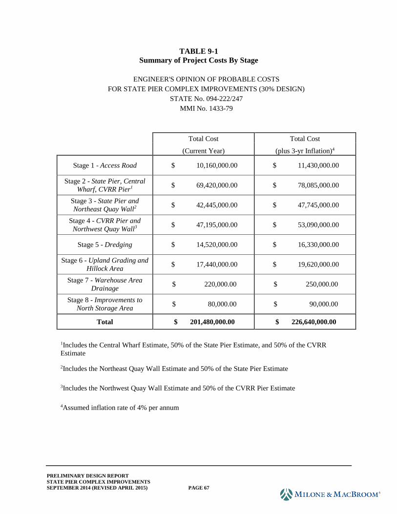
PRELIMINARY DESIGN REPORT
STATE PIER COMPLEX IMPROVEMENTS
SEPTEMBER 2014 (REVISED APRIL 2015) PAGE 67
TABLE 9-1
Summary of Project Costs By Stage
ENGINEER'S OPINION OF PROBABLE COSTS
FOR STATE PIER COMPLEX IMPROVEMENTS (30% DESIGN)
STATE No. 094-222/247
MMI No. 1433-79
Total Cost Total Cost
(Current Year) (plus 3-yr Inflation)4
Stage 1 - Access Road $ 10,160,000.00 $ 11,430,000.00
Stage 2 - State Pier, Central
Wharf, CVRR Pier1 $ 69,420,000.00 $ 78,085,000.00
Stage 3 - State Pier and
Northeast Quay Wall2 $ 42,445,000.00 $ 47,745,000.00
Stage 4 - CVRR Pier and
Northwest Quay Wall3 $ 47,195,000.00 $ 53,090,000.00
Stage 5 - Dredging $ 14,520,000.00 $ 16,330,000.00
Stage 6 - Upland Grading and
Hillock Area $ 17,440,000.00 $ 19,620,000.00
Stage 7 - Warehouse Area
Drainage $ 220,000.00 $ 250,000.00
Stage 8 - Improvements to
North Storage Area $ 80,000.00 $ 90,000.00
Total $ 201,480,000.00 $ 226,640,000.00
1Includes the Central Wharf Estimate, 50% of the State Pier Estimate, and 50% of the CVRR
Estimate
2Includes the Northeast Quay Wall Estimate and 50% of the State Pier Estimate
3Includes the Northwest Quay Wall Estimate and 50% of the CVRR Pier Estimate
4Assumed inflation rate of 4% per annum
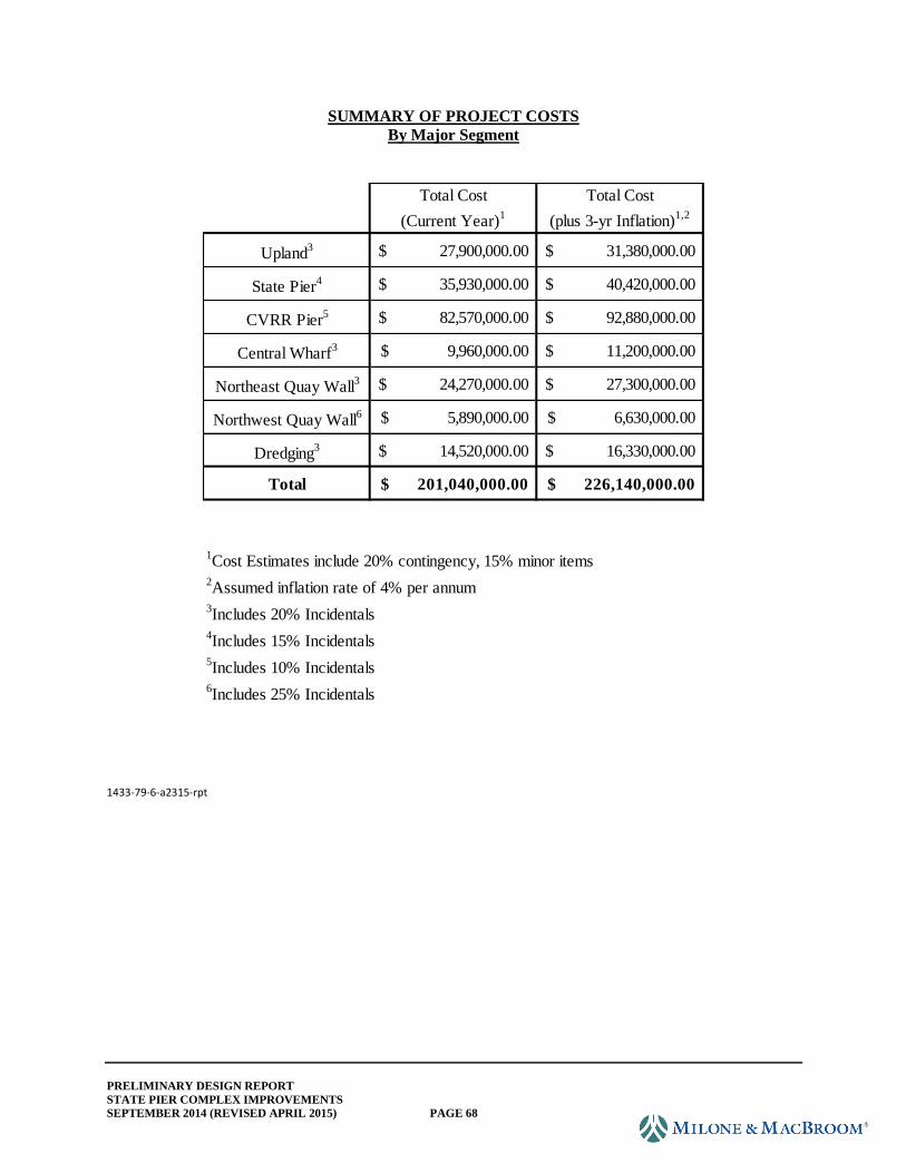
PRELIMINARY DESIGN REPORT
STATE PIER COMPLEX IMPROVEMENTS
SEPTEMBER 2014 (REVISED APRIL 2015) PAGE 68
SUMMARY OF PROJECT COSTS
By Major Segment
1433-79-6-a2315-rpt
Total Cost Total Cost
(Current Year)1
(plus 3-yr Inflation)1,2
Upland3 27,900,000.00$ 31,380,000.00$
State Pier4 35,930,000.00$ 40,420,000.00$
CVRR Pier5 82,570,000.00$ 92,880,000.00$
Central Wharf3 9,960,000.00$ 11,200,000.00$
Northeast Quay Wall3 24,270,000.00$ 27,300,000.00$
Northwest Quay Wall6 5,890,000.00$ 6,630,000.00$
Dredging3 14,520,000.00$ 16,330,000.00$
Total 201,040,000.00$ 226,140,000.00$
1Cost Estimates include 20% contingency, 15% minor items
6Includes 25% Incidentals
4Includes 15% Incidentals
5Includes 10% Incidentals
3Includes 20% Incidentals
2Assumed inflation rate of 4% per annum
APPENDIX A
Topographic and Hydrographic Survey
APPENDIX B
Geotechnical Information
APPENDIX C
Pier Inspection Report
APPENDIX D
American Marine Highway Design Report
APPENDIX E
Key Stakeholder Meeting Minutes and Correspondence
APPENDIX F
Cost Estimates