Embed Size (px)
Citation preview

PRELIMINARY ANALYSIS OF QUASI-STEADY STATE PRESSUREOSCILLATIONS OF AN OVERLOADED VEGA FIRST STAGE BY
MEANS OF Q1D MODELLING
Bernardo Favini∗1, Enrico Cavallini†1, and Agostino Neri‡2
1Sapienza University of Rome - Dept. of Mechanical and Aerospace Engineering, Rome, Italy2ESA ESRIN - VEGA Integrated Project Team, Frascati (Rome), Italy
Abstract
The operative life of many large solid rocket motors (e.g. USSpace Shuttle SRM, Ariane 5 P230 SRM, Titan SRM, P80SRM, the five-segment test motor ETM-3) is characterizedby the presence of sustained longitudinal pressure and thrustoscillations during their quasi-steady state, that may inducesevere impact on the payload comfort and on the dynamic op-erational environment of the launch vehicle. This paper isaimed at providing a first assessment of the pressure oscil-lations during the quasi-steady state of the new large mono-lithic SRM foreseen in the future configuration of VECEP up-graded first stage, that share the concept to be an over-loadedversions of the current VEGA first stage P80. The SRM con-figuration selected is inspired to the P105, VECEP first stage,designed as a stretched version of the P80 SRM, with an aft-finocyl configuration and the nozzle configuration of the P80.The numerical simulation of the SRM pressure oscillations isperformed by means of a Q1D model, named AGAR (Aero-dynamically Generated Acoustic Resonance), which set-up isbased on the data of pressure oscillations provided by all theP80 firings (static firing tests: P80 DM and QM and VEGAflights: VV01 and VV02) . To this aim, an analysis of the P80firings is performed in order to identify from the experimentaldata, the occurrence of the pressure oscillations phenomenaand their repeatability among the firings, showing clearly thatthe P80 is characterized by the presence of four time windowsof sustained pressure oscillations during the firing (B0, B1, B2and B3). The results of the numerical simulations for the P80,properly set-up to reproduce with reasonable assumption onthe semi-empirical model of AGAR code, are in good agree-ment with the experimental data (especially for the B0 andB1). Results for the P80 XL stretched tentative configurationshows that also the this tentative configuration is character-ized during its quasi-steady state by the presence and the oc-currence of pressure blows, in three time windows during thefiring (B0, B1 and B2). Moreover, a first assessment indicates
∗Associate Professor. [email protected]†Research Fellow. [email protected]‡Vega Senior Principal Engineer. [email protected]
that the level of the pressure oscillations of higher with re-spect to the one shown by the P80 and, as expected, is due tothe excitement of only the first acoustic mode of the chamber.
1 Introduction
The operative life of many large solid rocket motors (e.g. USSpace Shuttle SRM, Ariane 5 P230 SRM, Titan SRM, P80SRM, the five-segment test motor ETM-3) is characterized bythe presence of sustained longitudinal pressure and thrust os-cillations during their quasi-steady state. The frequency ofthe pressure oscillations is close to the first, but sometimesalso second or third acoustic modes frequencies of the com-bustion chamber. Although they do not compromise the mo-tor life, such oscillations may represent an important issue,which has to be accounted for at the system level, because ofthe two following main reasons: the SRM internal ballisticseffects on the overall structure of the launcher and the effectsof the pressure oscillations on the thrust yielded by the SRM.The assessment of the pressure oscillations time windows andamplitude represents an input for the structures dimension-ing, above all, for the stages interfaces ones and the payloadadapter, in order to correctly characterize the dynamic envi-ronment of the payload (e.g. Ariane 5 use of a damper in thepayload adapter flight configuration, in order to reduce thedynamic environment transmitted by the launcher to the pay-load). Furthermore, when pressure oscillations arise in dualbooster configurations (e.g. Ariane 5 or similar SRMs), thesecan constrain at the launcher system level, for the thrust vectorcontrol system. Indeed, the pressure oscillations are typicallyof the order of about 0.5 % of the mean value, whereas, dueto the transfer function between pressure and thrust, the or-der of the thrust oscillations can be about 5 % of the meanvalue. For these reasons, the understanding and analysis ofthe pressure oscillations onset in SRMs represents an impor-tant task, principally in order to have the capability to definetheir possible presence and their characterization during theSRM quasi-steady state.At the present state of the art, really, the main difficulty is
1

not represented by the understanding of the onset mechanismsof the pressure oscillations, which are quite well known [1],but rather by the capability in defining the actual onset of thepressure oscillations, in terms of, in order of importance, am-plitude, time windows and frequencies. This paper, therefore,discusses the developments of a Q1D model of the pressureoscillations, already presented in the recent past [2–4]. Thepurpose is to develop a reduced model (in the spirit of themodels presented in the past for the analysis of the aeroa-coustic phenomena in Refs. [1, 5–11]) of the pressure oscil-lations phenomena in SRMs, more detailed than the typicalRossiter [12] and/or Strouhal analyses, but in the meantime,more useful, at a system level, than full 3D numerical simula-tions [13–17] for the evaluation of the thrust oscillations andacceleration environment brought about in the SRM, becauseof the pressure oscillations onset.Aim of the present study is to present: 1) the results of thereconstruction of the P80 SRM pressure oscillations consid-ering all the data coming from the static firing tests (P80 DMand QM) and VEGA flights (VV01 and VV02); 2) on the baseof this reconstruction to investigate the onset of pressure os-cillations during the quasi-steady state of the new large mono-lithic SRM foreseen in the future configuration of the VECEPupgraded first stage, that has the concept to be an over-loadedversion of the current VEGA first stage P80. The SRM config-uration selected is, hence, inspired to the P105, VECEP firststage, designed as a stretched version of the P80 SRM, with anaft-finocyl configuration, with the same overall characteristicsof the P80 SRM in terms of nozzle design and materials.
2 Internal Ballistics Q1D Model ofSRMs Acoustic Resonance
The model developed for the pressure oscillations simulationduring the SRM internal ballistics, named AGAR (Aerody-namically Generated Acoustic Resonance) is composed bythe following sub-models: a model of the SRM internal bal-listics, a model for the grain burnback simulation and anaeroacoustic model. The SRM internal ballistics model isthe SPINBALL (Solid Propellant rocket motor INternal BAL-Listics), created for the analysis of solid rocket motor in-ternal ballistics and already completely developed and val-idated [18–23]. A detailed description of SPINBALL canbe found in Ref. 23. The internal ballistics model consid-ers an unsteady quasi-one-dimensional Eulerian model, withmass, momentum and energy addition and a geometrical evo-lution both in space and time. The governing equation are dis-cretized by a Godunov-type scheme, accurate at first or sec-ond order in space and time. The main model is completedby different sub-models in order to describe the SRM ignitiontransient and nozzle throat ablation phenomena [19].
The grain burnback model is a 3D numerical simulation ofthe propellant grain burning surface evolution in time, nameGREG [23, 24], based on a level set technique properly tai-lored to the evolution of the combustion surface of SRMs.
The model makes available all the geometrical parameters re-quired for the solution of the internal ballistics to the SPIN-BALL model with a loose coupling strategy, as described inRef. 23.
The aeroacoustic model is composed by the following sub-models: a model to determine the vortex dynamics (creation,growth, convection and destruction), a model to evaluate theacoustic field excitation by vortex shedding phenomenon anda model to estimate the acoustically forced vortex generation.A Q1D equation describes the vorticity convection in the flow.The acoustic modes excitation due to vortex impingement ismodeled with the introduction of source terms in the SPIN-BALL gasdynamic model. Section 2.1 describes the last de-velopments of the acoustic module, with respect to the onespresented in Ref. 2, 3, 25.
2.1 Vortex Sound Q1D ModelIn order to describe in a Q1D model the dynamics of the vor-ticity, a further scalar equation has to be added to the stan-dard set of the Q1D unsteady Euler equations, heritage of theSPINBALL model [23]. In fact, in a Q1D fashion, only theazimuthal component of the vorticity, concurrently orthogo-nal to the motor axial and radial directions, has to be modeled.Differently from the derivation of the presented in Ref. 3, 25,we recast the vorticity equation in a more compact formula-tion, as will be explained in the following.
The derivation of a Q1D equation for the vorticity equationstarts from the multidimensional vorticity equation in cylin-drical coordinates, with the additional assumptions of axisym-metric flow ( uθ = (·)θ = 0) and, then, averaging over thesection the conservative form of the resultant equation. Then,we neglect the baroclinic term, since it becomes importantonly for problems involving the vorticity created by gravitywaves (for atmospheric problems, involving incompressibleand inhomogeneous fluids and Rayleigh-Taylor instability) orthe passage of a shock in a inhomogeneous fluid (Richtmeyer-Meshkov instability). With the assumption of axisymmetricflow, the equation can be reduced in a scalar equation of theazimuthal vorticity ω, as expressed in Eq. (1). In Eq. (1), thefollowing symbols have been introduced: ω, azimuthal com-ponent of the vorticity; u, component of the velocity alongthe SRM axis x; ur, the radial component of the velocity andwith r the radial direction.
∂ω
∂t+∂ (uω)
∂x= − ∂ (ur ω)
∂r︸ ︷︷ ︸radial flux term
(1)
Last equation can be recast, finally, in a Q1D fashion, as-suming averaged values of the quantities in the section area,bringing to the Eq. (2), where the port area Ap and the radialboundary of the control volume ∆, have been introduced.
∂ (ωAp)
∂t+∂ (v ωAp)
∂x= −
∫∂∆
∂ (ur ω)
∂rd∆︸ ︷︷ ︸
radial flux term
(2)
2

In Eq. (2), an advection velocity of the vortices v in theflowfield has been introduced, different from the Q1D meanvelocity of the flow u. This vortices advection velocity ismodeled as proportional to the Q1D flowfield mean velocity,as expressed by Eq. (3).
v = ku u (3)
In fact, it is know that a Q1D model, since it averages thequantities of the flowfield in the section overestimates the ve-locity of the flow, especially in the case of SRMs, in whichmass addition and rotation of the streamlines, from the pro-pellant surface towards the motor axis, occur. Moreover, theadvection velocity of the vorticity represents a key parame-ter for the aeroacoustic coupling and, therefore, in the lock-inprocess between the two loops: generation of vortices from ashear layer instability at the corner, their advection in the flow-field and emission of acoustic energy (loop 1) and the effectsof chamber natural modes on the vortices generation (loop 2).
The radial addition of vorticity is modeled considering onlythe case of a production of vorticity due to the presence ofa corner. Therefore, the radial flux of vorticity caused by ashear layer instability is assumed to be the variation in timeof the circulation Γ (Eq. (4)). In turn, the vortex propertiescharacterized by the variation of the circulation of the averageflowfield are considered a function of the time varying flowconditions. If the velocity at the outer edge of the boundarylayer is assumed composed by the mean flow velocity u andacoustic component u′, the rate of circulation of the flowfieldand, hence, the radial flux of the vorticity equation can beexpressed by Eq. (4).∫
∂∆
∂ (ur ω)
∂rd∆︸ ︷︷ ︸
radial flux term
=dΓ
dt= kΓ u
2 (t) (4)
In Eq. (4), a calibration parameter has been considered inthe proportional relationship between the rate of circulationand the velocity outside the boundary layer. Moreover, thesource term on the left hand side of the equation representsthe effect on the vortex shedding of the flowfield condition(loop 2). The radial flux of vorticity created by a shear layerinstability is considered, as for the previous formulation of themodel, only in case of the vortex shedding by angle, due to thepresence of a corner in the propellant grain geometry, which isdetected and traced during the numerical simulation. The leftside hand of Eq. (2) is active, hence, only in then corner, afterthe detachment of the vortex itself in the flowfield. The casesof obstacle and parietal vortex shedding/vorticity productionare, hence, neglected.
As far as the vortex characterization before its detachmentin the flowfield is concerned, a detachment criterion is de-veloped as a function of time varying flow conditions. Thecriterion is the one already presented in Ref. 3, 25 and con-siders local pressure evolution at the shedding point, i.e. thecorner point (CP) of the geometry, defining again the role of
the acoustic feedback on vortex shedding dynamics. This rep-resents another modeled effect of the loop 2. The vortex sep-aration is imposed each time the pressure evolution of the de-tachment point that is a descending node (which correspondsto a positive velocity anti-node).
In order to describe the loop 1 of the hydrodynamic insta-bility mechanism, sources terms are added to the standard setof Q1D Euler equations, representing the flowfield model ofSPINBALL. These terms represent the acoustic excitementof the flowfield due to vortices interaction/impingement withobstacles and or, in general, the combustion chamber geom-etry after the vortex detachment itself (e.g. submerged noz-zle). The expressions introduced to model the source termsfor the mass, momentum and energy equation, as closure ofthe model, derives from a heuristic process.
mvs = 0
qvs = ρωa
(∂A
∂x
)L
evs = qvs u
(5)
The mass source term is assumed to be zero, so that thevortex impingement only generates momentum and energysource terms. A phenomenological description, combinedwith a dimensional analysis, determines the expressions givenin Eq. (5). The sound generation is active each time a vor-tex interacts with a geometrical variation. The influence ofthe vortex intensity is represented directly by the vorticity,whereas the sound generation due to the presence of obstaclesto the vortices advection in the chamber geometry is describedby the term of area variation along the SRM axis.
3 P80 Pressure OscillationsThis section briefly discusses the numerical simulation ofthe pressure oscillations during the quasi-steady state of P80SRM. For the P80 SRM, in fact, two static firing tests (P80DM and P80 QM) and the two VEGA flights (VV01 andVV02) represent a quite wide of firings in order to have aclear image of the pressure oscillations phenomena occurringduring the P80 operative time, in terms of their repeatabil-ity/dispersion and main characteristics: windows of occur-rence, amplitude and frequency content.
These data will be in fact used in order to set-up the semi-empirical parameters present in the AGAR Q1D model, and,as comparison, in order to show the open issues and modellacks to be improved. In particular, for a first assessment ofthe pressure oscillations of a tentative P80 XL stretched SRM,a conservative set-up of the pressure oscillations will be per-formed.
From the analysis of the experimental data, the followingcharacteristics of the pressure oscillations characterizing theP80 quasi-steady state can be outlined (see Figure 2 and Fig-ure 3). Figure 2 shows the envelope of the maximum absolutevalues of the pressure oscillations over time experienced dur-ing the P80 SFTs DM and QM and the VEGA flights VV01
3

Figure 1: P80 - Experimental Pressure Evolution in Time -Non-dimensional
Figure 2: P80 Firings - Pressure Oscillations Absolute Maxi-mum Envelope - Non-dimensional
and VV02. Figure 3 shows instead the Hilbert-Huang [26]transform of the pressure oscillations experimental signal overtime. All the data are represented in a non-dimensional formfor confidentiality reasons. The P80 pressure oscillations ap-pear to be repetitive among the firing, both the SFTs and theflights. Four different blows (appearance of pressure oscilla-tions onset) are clearly present both for the static firing tests(DM and QM) and the flights (VV01 and VV02): namely B0,B1, B2 and B3. The first blow (B0) has maximum amplitudeand time window is quite dispersed among the firings and oc-curs immediately after the end of the SRM start-up, lastingfor some seconds (see Figure 1). The second blow (B1) is
the most repetitive among all the firings, in terms of both themaximum amplitude and window of occurrence and happensaround the reaching of the SRM maximum operative pressureand during the pressure decreasing before the knee of the pres-sure curve (see Figure 1). The third blow (B2) present a timewindow of occurrence with a small dispersion for its end timeof occurrence and a high dispersion for its starting time andoccurs between the head-end pressure curve knee. Anyhow,like the B0, the dispersion of the B2 time window seems tobe related to a dispersion of the blow amplitude among thefirings. The fourth blow (B3) has a maximum amplitude witha small dispersion among the firing, whereas its time windowis a bit dispersed among DM, QM, VV01 and VV02, with astarting time roughly constant and an end time which varies ofsome seconds, during the phase of slow increase of the pres-sure (see Figure 1).
Figure 3: P80 VV02 - Pressure Oscillations Hilbert-HuangTransform - Non-dimensional
For all the blows, the frequency content is always related tothe first acoustic mode of the P80 combustion chamber, with-out any involvement of the higher fundamental modes (sec-ond, third mode) of the combustion chamber. In particular,the frequency of the pressure blows shifts slightly during thefiring, with a small increase among each blow, whereas theaverage frequency of each blow remains constant, in a sort ofstep-wise trend (Figure 3).
In the following of this section, the numerical simulationshowing the internal ballistics simulations of the P80 will bepresented and compared with the experimental data analysisshown in Figure 2 and Figure 3. The numerical simulationof the internal ballistics exploits the reconstruction of the P80DM and QM static firing tests [21, 27]. In particular, the sim-ulation set-up has considered as reference the set-up of theQM SFT, which represents, in terms of pressure profile, a ref-erence for the VV01 and VV02 flights. Instead, the P80 DMSFT was intentionally designed to work at a lower average op-
4

erating pressure with respect to the QM SFT. The numericalsimulation, hence, considers all the SRM non-ideal param-eters in the simulation (scale factor, hump and combustionefficiency), as well as the nozzle throat erosion.
Figure 4 shows the pressure oscillations extracted by thenumerical pressure trace by removing the carrier pressure.The numerical simulation shows the presence of three timewindows of sustained pressure oscillations during the quasi-steady state, named B0, B1 and B2-B3, with reference to theexperimental ones shown in Figure 2. By the comparisonof the numerical simulation (Figure 4) with the experimentaldata (Figure 2), a quite satisfactory representation of the pres-sure blows in terms of amplitude and time windows of occur-rence is shown. Note that the simulation set-up of the AGARmodel has been chosen intentionally to have a good correla-tion with the experimental data with reasonable values of thecalibration parameters ku and kΓ, which modify respectivelythe advection velocity in the flowfield of the vorticity emittedby the corner of the finocyl geometry and the intensity of thevorticity generated by the shear layer instability at the corner.Anyhow, the rationale of the model set-up is to have a conser-vative assessment of the pressure oscillation amplitude witha good correlation of the time occurrence of the blows withthe experimental data, but no fine calibration of the model hasbeen considered.
Figure 4: P80 Numerical Simulation - Non-dimensional Pres-sure Oscillations
The results shows that the B0 and B1 blows are quite wellcaptured by the model in terms of both the amplitude and thetime windows of occurrence and also the modulation of theamplitude inside each blow is represented in a quite satisfac-tory way (compare each other Figure 4 and Figure 2). Instead,for the B2 and B3 some differences among the result of the nu-merical simulation and the experimental data are present. Inparticular, whereas the initial time of onset of the B2 is quitewell represented (with reference to DM, QM and VV02) by
AGAR, the numerical simulation shows one single blow in-stead of the two present in all the experimental data, and alsothe blow amplitude and its modulation over time are differ-ent between the simulation and the firings. By the analysis ofthe flowfield and the SRM configuration during occurrence ofthe blows, however, there is an qualitative difference amongthe first two blows of the P80 (B0 and B1) and the third andfourth blow (B2 and B3). Indeed, B0 and B1 occur in a phasefor the SRM internal ballistics in which the submergence re-gion contains a large amount of propellant and produce a largeamount of mass and energy. Therefore, the most part of themass addition from the propellant grain occurs from the finsof the propellant grain geometry and the flowfield patterns in-side the submergence region during the B0 and B1 is differentfrom the one of a “passive” cavity, with a recirculation in-side. Instead, for the B2 and B3, the aft-finocyl propellantgrain configuration is such that at their time of occurrence,the submergence region is almost empty of residual propel-lant and the situation in terms of mass addition distributioninside the motor is completely reversed, so that the submer-gence region contribution to the pressure oscillations changesfrom the B0-B1 to B2-B3. Inert (“passive”) cavities presentinside the SRM and, in particular, of the submergence regionare known [28] to play a relevant role in the SRM resonance.
Figure 5: P80 Numerical Simulation - Pressure OscillationsHilbert-Huang Transform - Non-dimensional
Therefore, whereas from a pure quantification of the pres-sure blows the results appear to be satisfactory, in order toimprove the reduced order model characterization of the pres-sure oscillations, more deepened investigations are necessaryon the cavity model present in the AGAR code. In fact, fromsome investigations performed and the results shown, the cav-ity model formulation appears to be representative of the mo-tor submergence region role in the pressure oscillations phe-nomena when it is a cavity with a relevant mass and energy
5
addition, as during B0 and B1. Whereas, when it becomes anempty cavity, as during B2-B3, some room for further inves-tigations and model developments is to be considered.
Figure 5 shows the Hilbert-Huang transform of the pres-sure signal coming from the numerical simulation of the P80,in order to analyze the frequency content of the pressure os-cillations. The numerical results show a slight overestimation(20 % maximum) of the frequency of the pressure oscillationsfor all the blows, as a characteristic of the Q1D model. More-over, as expected, there is not an increase of the frequencyof the pressure oscillations along time for the numerical sim-ulation, since out of the model prediction capabilities for aQ1D approach. Some improvements of the results are ex-pected from considering the two-phase flow effects, which areknown to lower the chamber acoustic frequency. Anyhow, fora reduced order model, the results are considered satisfactoryin terms of the characterization in the frequency domain of theP80 blows, and as the experimental data, a part from the firstchamber acoustic mode, no involvement of the higher naturalmodes of the chamber is present in the numerical simulation.
4 P80 XL stretched Pressure Oscilla-tions Numerical Simulation
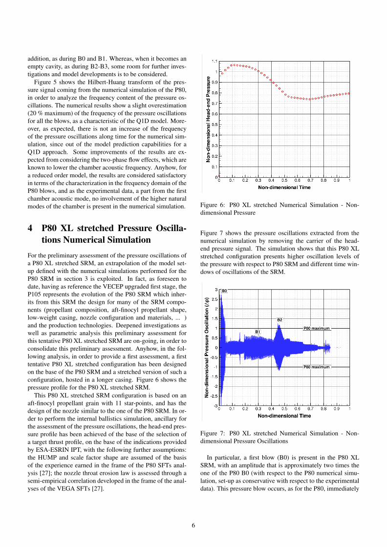
For the preliminary assessment of the pressure oscillations ofa P80 XL stretched SRM, an extrapolation of the model set-up defined with the numerical simulations performed for theP80 SRM in section 3 is exploited. In fact, as foreseen todate, having as reference the VECEP upgraded first stage, theP105 represents the evolution of the P80 SRM which inher-its from this SRM the design for many of the SRM compo-nents (propellant composition, aft-finocyl propellant shape,low-weight casing, nozzle configuration and materials, ... )and the production technologies. Deepened investigations aswell as parametric analysis this preliminary assessment forthis tentative P80 XL stretched SRM are on-going, in order toconsolidate this preliminary assessment. Anyhow, in the fol-lowing analysis, in order to provide a first assessment, a firsttentative P80 XL stretched configuration has been designedon the base of the P80 SRM and a stretched version of such aconfiguration, hosted in a longer casing. Figure 6 shows thepressure profile for the P80 XL stretched SRM.
This P80 XL stretched SRM configuration is based on anaft-finocyl propellant grain with 11 star-points, and has thedesign of the nozzle similar to the one of the P80 SRM. In or-der to perform the internal ballistics simulation, ancillary forthe assessment of the pressure oscillations, the head-end pres-sure profile has been achieved of the base of the selection ofa target thrust profile, on the base of the indications providedby ESA-ESRIN IPT, with the following further assumptions:the HUMP and scale factor shape are assumed of the basisof the experience earned in the frame of the P80 SFTs anal-ysis [27]; the nozzle throat erosion law is assessed through asemi-empirical correlation developed in the frame of the anal-yses of the VEGA SFTs [27].
Figure 6: P80 XL stretched Numerical Simulation - Non-dimensional Pressure
Figure 7 shows the pressure oscillations extracted from thenumerical simulation by removing the carrier of the head-end pressure signal. The simulation shows that this P80 XLstretched configuration presents higher oscillation levels ofthe pressure with respect to P80 SRM and different time win-dows of oscillations of the SRM.
Figure 7: P80 XL stretched Numerical Simulation - Non-dimensional Pressure Oscillations
In particular, a first blow (B0) is present in the P80 XLSRM, with an amplitude that is approximately two times theone of the P80 B0 (with respect to the P80 numerical simu-lation, set-up as conservative with respect to the experimentaldata). This pressure blow occurs, as for the P80, immediately
6

after the SRM ignition (see Figure 6 and Figure 7) Then, othertwo time windows of relevant pressure oscillations are presentin the numerical simulation: identified with B1 and B2 (whichare almost contiguous in time). The first one (B1) occurs dur-ing the phase of the pressure decreasing after the achievementof the motor maximum operative pressure. The second one(B2) occurs, as for the P80, between the knee of the pres-sure curve, characteristic of the aft-finocyl first stages SRMs.In particular, the B2 has a relevant amplitude, in comparisonwith the amplitude shown by the B2 for the P80. Note that,for the SRM configuration designed, the P80 XL stretched hasa submergence cavity that is consumed in a later time with re-spect to the P80 SRM.
Figure 8: P80 XL stretched Numerical Simulation - PressureOscillations Hilbert-Huang Transform - Non-dimensional
Figure 8 depicts the Hilbert-Huang transform of the pres-sure signal coming from the numerical simulation of the P80XL. As expected, the frequency of the pressure oscillations islower with respect to the one of the P80, since the SRM in in-tentionally designed with a longer combustion chamber and,therefore, a lower first acoustic frequency.
5 Conclusions
A preliminary assessment of the pressure oscillations duringthe quasi-steady state of a tentative configuration of the P80XL stretched SRM, with reference to the P105 upgraded VE-CEP first stage, is performed through the use of a Q1D model,named AGAR, and discussed in this paper. Even if detailedand deepened analyses are on-going, this preliminary assess-ment is rooted on a conservative model set-up based on theanalysis of the available experimental data from the P80 fir-ings, achieved in the frame of the development and qualifica-tion phase of the VEGA launch vehicle. Therefore, in order to
perform a preliminary and conservative assessment of a possi-ble pressure oscillations scenario of a P80 XL stretched SRM,a re-analysis of all the data available from the VEGA firings(SFTs, DM and QM and flights, VV01 and VV02) has beenperformed. The analysis of the experimental data shows thatthe P80 is characterized by four different pressure oscillationstime windows: B0, B1, B2 and B3. The numerical simulationof the P80, set-up as basis for the experimental data, showsthat the AGAR model is able to characterize with a good cor-relation with the experimental data the first two blows (B0and B1), whereas some discrepancy are present with respectto B2 and B3, that is characterized by a unique blow by the nu-merical simulation, with a slight underestimation of the blowamplitude and amplitude modulation in time. Therefore, evenif for a reduced order model, a satisfactory estimation of theP80 blow is shown, this fact indicates the need of further in-vestigations to characterize the role of the submergence cav-ity of the AGAR model, which appears adequate for cavitieswith propellant inside and to be improved for cavities withoutpropellant, as during the B2 and B3. Then, a tentative P80 XLstretched SRM configuration has been built-up considering anoverloading of the P80 SRM propellant grain configurationand assuming, for a first assessment, a design of the nozzlesimilar to the one of the P80 SRM. The preliminary numeri-cal simulations performed indicate that, as the P80 SRM, theP80 XL show the presence of sustained pressure oscillationsduring its quasi-steady state. The level of amplitude of thesepressure oscillations is higher with respect to the P80 SRM.Three pressure blows can be identified, with some similaritieswith respect to the P80 ones, in terms of characteristic time ofoccurrence on the pressure profile: the first one, immediatelyafter the ignition phase, the second one after the achievementof the SRM maximum operative pressure and the third onebetween the pressure curve knee. Further parametric analysesand investigations are on-going to consolidate this first assess-ment.
Acknowledgments
This work is supported and funded by the ESA-ESTEC/Contract No. 4000101871/10/I/JD. All the requiredmotor data have been kindly granted by ESA ESRIN VEGAIntegrated Project Team.
VEGA launch vehicle has been developed within an Eu-ropean Program promoted by the European Space Agency(ESA), as a cooperative project with Member States withinthe ESA framework. VEGA Programme has been managedby an Integrated Project Team that, under the responsibilityof the European Space Agency, involves also staff from theItalian (ASI) and French (CNES) Space Agencies.
The first stage motor, P80 FW SRM, has been developedthrough a parallel ESA Programme, under responsibility ofESA/CNES. AVIO S.p.a. is the prime contractor for the P80with the technical management delegation to Europropulsion,France.
7

REFERENCES
[1] Flandro, G., “Vortex driving mechanism in oscillatoryrocket flows,” J. Propulsion and Power, Vol. 2, No. 3,1986, pp. 206–214.
[2] Ferretti, V., Favini, B., Cavallini, E., Serraglia, F., andGiacinto, M. D., “Numerical simulations of acousticresonance of Solid Rocket Motor,” AIAA-2010-6996,July 2010, 46th AIAA/ASME/SAE/ASEE Joint Propul-sion Conference and Exhibit, Nashville, TN, July 25-28,2010.
[3] Ferretti, V., Favini, B., Cavallini, E., Serraglia, F., andGiacinto, M. D., “Pressure oscillations simulation in P80SRM first stage VEGA launcher,” AIAA-2011-6055,July 2011, 47th AIAA/ASME/SAE/ASEE Joint Propul-sion Conference and Exhibit, San Diego, California,July 31-3 August, 2011.
[4] Cavallini, E., Ferretti, V., Favini, B., Di Giacinto, M.,and Serraglia, F., “Pressure Oscillations Numerical Sim-ulation in Solid Rocket Motors,” AIAA 2012-3824, Au-gust 2012, 48th AIAA/ASME/SAE/ASEE Joint Propul-sion Conference and Exhibit, 30 July - 1 August 2012,Atlanta, Georgia.
[5] Culick, F., “Acoustic oscillations in solid propellantrocket chambers,” Astronautica Acta, Vol. 12, No. 2,1966, pp. 113–126.
[6] Matveev, K. and Culick, F., “A model for combustioninstability involving vortex shedding,” Combustion Sci-ence and Technology, Vol. 175, No. 6, 2003, pp. 1059–1083.
[7] Matveev, K., “Reduced-order modeling of vortex-drivenexcitation of acoustic modes,” Acoustics Research Let-ters Online, Vol. 6, 2005, pp. 14.
[8] Menon, S. and Jou, W., “Numerical simulations of oscil-latory cold flows in an axisymmetric ramjet combustor,”Journal of Propulsion and Power, Vol. 6, 1990, pp. 525–534.
[9] Jou, W., “Modes of oscillation in a nonreacting ram-jet combustor flow,” Journal of Propulsion and Power,Vol. 6, 1990, pp. 535–543.
[10] Ananthkrishnan, N., Deo, S., and Culick, F., “Reduced-order modeling and dynamics of nonlinear acousticwaves in a combustion chamber,” Combustion scienceand technology, Vol. 177, No. 2, 2005, pp. 221–248.
[11] Darmofal, D., Khan, R., Greitzer, E., and Tan, C., “Vor-tex core behaviour in confined and unconfined geome-tries: a quasi-one-dimensional model,” Journal of FluidMechanics, Vol. 449, 2001, pp. 61–84.
[12] Rossiter, J., “The effect of cavities on the buffeting ofaircraft,” Royal Aircraft Establishment Technical Mem-orandum, Vol. 754, 1962.
[13] Ballereau, S., Godfroy, F., Guery, J., and Ribereau, D.,“Assessment on Aalysis and Prediction Method Appliedon Thrust Oscillations of Ariane 5 Solid Rocket Motor,”39th AIAA/ASME/SAE/ASEE Joint Propulsion Con-ference and Exhibit, Huntsville, AL, July 2003, AIAAPaper 2003-4675.
[14] Fabignon, Y., Dupays, J., Avalon, G., Vuillot, F., Lu-poglazoff, N., Casalis, G., and Prévost, M., “Instabil-ities and pressure oscillations in solid rocket motors,”Aerospace science and technology, Vol. 7, No. 3, 2003,pp. 191–200.
[15] Ballereau, S., Godfroy, F., Orlandi, O., and Bal-lion, D., “Numerical Simulations and Searching Meth-ods of Thrust Oscillations for Solid Rocket Boost-ers,” AIAA Paper 2006-4425, July 2006, 42nd
AIAA/ASME/SAE/ASEE Joint Propulsion Conference,Sacramento, California.
[16] Guery, J., Ballereau, S., Godfroy, F., Gallier, S., Or-landi, O., and Della Pieta, P., “Thrust oscillations in solidrocket motors,” AIAA Paper 2008-4789, July 2008, 44th
AIAA/ASME/SAE/ASEE Joint Propulsion Conferenceand Exhibit, 21-23 July 2008, Hartford, Connecticut.
[17] Ballereau, S., Godfroy, F., Orlandi, O., Gallier, S.,Guery, J., and Cesco, N., “Thrust Oscillations in SRM,”Space Propulsion 2008 - 2nd International Symposiumon Propulsion for Space Transportation, Heraklion -Crete, Greece, May 2008.
[18] Cavallini, E., Favini, B., Di Giacinto, M., and Serraglia,F., “Internal Ballistics Simulation of a NAWC TacticalSRM,” Journal of Applied Mechanics ISSN: 0021-8936;eISSN: 1528-9036, , No. JAM-10-1424, pre-print avail-able on journal webpage.
[19] Cavallini, E., Bianchi, D., Favini, B., Di Giacinto,M., and Serraglia, F., “Internal Ballistics Modeling ofHigh Performance SRMs with Coupled Nozzle ErosionCharacterization,” AIAA 2011-5799, July 2011, 47th
AIAA/ASME/SAE/ASEE Joint Propulsion Conferenceand Exhibit, 31 July - 3 August 2011, San Diego, CA.
[20] Cavallini, E., Favini, B., Di Giacinto, M., and Ser-raglia, F., “Internal Ballistics Simulation of NAWC Tac-tical Motors with SPINBALL Model,” AIAA 2010-7136, DOI: 10.2514/6.2010-7136, July 2010, 46th
AIAA/ASME/SAE/ASEE Joint Propulsion Conferenceand Exhibit, Nashville, TN.
[21] Cavallini, E., Favini, B., Di Giacinto, M., and Serraglia,F., “SRM Q1D unsteady Internal Ballistics Simulationusing 3D Grain Burnback,” 2010, 3-6 May, San Sebas-tian, Spain.
8

[22] Cavallini, E., Favini, B., Di Giacinto, M., and Ser-raglia, F., “SRM Internal Ballistic Numerical Simulationby SPINBALL Model,” AIAA Paper 2009-5512, Aug.2009, 45th AIAA/ASME/SAE/ASEE Joint PropulsionConference and Exhibit, Denver, Colorado.
[23] Cavallini, E., Modelling and Numerical Simulation ofSolid Rocket Motors Internal Ballistics, Ph.D. thesis,Sapienza Università di Roma, 2010.
[24] Favini, B., Cavallini, E., Di Giacinto, M., and Ser-raglia, F., “An Ignition-to-Burn Out Analysis of SRMInternal Ballistic and Performances,” AIAA 2008-5141,July 2008, 44th AIAA/ASME/SAE/SEE Joint Propul-sion Conference and Exhibit, Hartford, Connecticut.
[25] Ferretti, V., Numerical simulations of acoustic reso-nance of Solid Rocket Motor, Ph.D. thesis, Universitàdegli Studi di Roma “La Sapienza”, 2011.
[26] Huang, N., Shen, Z., Long, S., Wu, M., Shih, H., Zheng,Q., Yen, N., Tung, C., and Liu, H., “The empirical modedecomposition and the Hilbert spectrum for nonlinearand non-stationary time series analysis,” Proceedings ofthe Royal Society of London. Series A: Mathematical,Physical and Engineering Sciences, Vol. 454, No. 1971,1998, pp. 903–995.
[27] Cavallini, E., Favini, B., Di Giacinto, M., and Serraglia,F., “Analysis of VEGA Solid Stages Static Firing Teststowards the Maiden Flight,” AIAA 2012-4211, August2012, 48th AIAA/ASME/SAE/ASEE Joint PropulsionConference and Exhibit, 30 July - 1 August 2012, At-lanta, Georgia.
[28] Anthoine, J., Buchlin, J., and Hirschberg, A., “Effectof nozzle cavity on resonance in large SRM: theoreticalmodeling,” Journal of Propulsion and power, Vol. 18,No. 2, 2002, pp. 304–311.
9