Embed Size (px)
Citation preview

PREFACE TO SECOND EDITION
FIRST EDITION First Printing - January, 1955
Second Printing - October, 1956 Third Printing - August, 1958
SECOND EDITION First Printing - November, 1959
RADIO RECEIVER SERVICING
Catalog Number : RS-2
Copyright @ 1959 by Howard W. Sams & Co., Inc. Copy- r ight 1955 by Howard W. Sams & Co., Inc., Indianapolis 6, Indiana. Printed in the United States of America.
Reproduction or use, without express permission, of edi- torial or pictorial content, in any manner, is prohibited. No patent liability is assumed with respect to the use of the information contained herein.
Library of Congress Catalog Card Number: 59-15240
Five years i s a long t ime in the rapidly expanding field of electronics, andthat i s how long it has been since the f i r s t edition of Radio Receiver Servicing was written. During those five years , solid-state rect i f iers have pretty well taken over in radio power supplies, twelve-volt auto s e t s have become standard, and the t rans i s to r has come into i t s own.
These advances, coupled with the warm reception given the f i r s t book, seemed to warrant a completely revised edition -- and that i s what this is. Every word of the original book has been carefully studied, weighed, changed, dis- carded, o r allowed to stand in the light of how accurately and helpfully i t descr ibes the radio se rv ice picture today. In addition, many thousands of new words, accompanied by new pictures and diagrams, have been added. What the wri ter has learned about servicing in those five years -- and a good technician lea rns every hour he stands a t the bench -- has been interwoven a s an added bonus.
Whenit was found that severa l schools were using the original edition a s a textbook -- although such use had not been anticipated - - i t was decided to add review questions a t the end of each chapter. These questions a r e carefully framed to underscore the most important points in the chapter.
The wr i te r hopes and believes the result is an honestly written, up-to-date book on radio receiver servicing that will be equally helpful to the practicing technician a t his bench, o r to the student in the classroom.
September, 1959 JOHN T. FRYE:

TABLE OF CONTENTS
Page INTRODUCTION . . . . . . . . . . . . . . . . . . . . . . . . . . . . . . . . . . . . 7
SECTION I .. NO RECEPTION
Chapter 1 .. The Dead Set . . . . . . . . . . . . . . . . . . . . . . . . . . . . . 17
Chapter 2 .. Tubes Light But No Sound . . . . . . . . . . . . . . . . . . . . . 29
Chapter 3 .. Only Slight Hum Is Heard . . . . . . . . . . . . . . . . . . . . . 40
Chapter 4 .. Only Noise Can Be Heard . . . . . . . . . . . . . . . . . . . . . 51
Chapter 5 .. Excessive Current Indication . . . . . . . . . . . . . . . . . . 60
SECTION I1 .. UNSATISFACTORY RECEPTION
. . . . . . . . . . . . . . . . . . . . . . . . . . . . . . . . . . . . . . . . . Forward 74
Chapter 6 .. Sets With Excessive Hum . . . . . . . . . . . . . . . . . . . . . 75
Chapter 7 .. Set Does Not Separate Stations . . . . . . . . . . . . . . . . . . 87
Chapter 8 .. Sets That Whistle, Motorboat, Etc . . . . . . . . . . . . . . . . 100
Chapter 9 .. Noisy Sets . . . . . . . . . . . . . . . . . . . . . . . . . . . . . . . 112
Chapter 10 .. Sets With Distortion . . . . . . . . . . . . . . . . . . . . . . . . 122
Chapter 11 .. Weak Sets . . . . . . . . . . . . , . . . . . . . . . . . . . . . . . . 132
* SECTION III .. INTERMITTENTS AND MISCELLANEOUS SERVICE PROBLEMS
. . . . . . . . . . . . . . . . . . . . . . . . . . . . . . . . . . . . . . . . . Forward 146
Chapter 12 .. Intermittent Loss of Reception . . . . . . . . . . . . . . . . . 147
Chapter 13 .. Intermittent Faulty Reception . . . . . . . . . . . . . . . . . . 159
Chapter 14 .. Transistor Receivers and Printed Circuits . . . . . . . . . 169
. . . . . . . . .. Chapter 15 Auto Radios and Storage-Battery Portables 184
.. . . . . . . . . . . . . . . . . . . . . . . Chapter 16 All-Wave and FM Sets 197
Conclusion . . . . . . . . . . . . . . . . . . . . . . . . . . . . . . . . . . . . . . . . 213
. . . . . . . . . . . . . . . . . . . . . . . . . . . Answers to Review Questions 214
INTRODUCTION
This is not another volume of radio theory; neither i s it an oversimplified introduction t o radio repairing. Instead, it is a down- to-earth book on how to repa i r radios and i s written directly for the man who is ready to make his living, o r a t least part of it , doing radio service.
Such a man, it i s fe l t ,wil l already have acquiredcertain mental and physical equipment necessary for the work to be done. In p r e - paring this book for him, therefore, it has been assumed that he has the following:
1. Basic Knowledge of Radio Theory.
This may have been obtained from a radio school, f rom elec- tronic instruction in the armed forces, o r f rom extensive reading. Many books on radio theory a r e available, but the one with which the wri ter i s most familiar i s his own BASIC RADIO COURSE; s o it will be taken for granted that the r e a d e r ' s understanding of how radio works i s a t least equal to the theory explained in that book.
2. A Complete Set of Service Li terature Covering All Sets Upon Which Work rVill Be Attempted.
The wiring diagrams, alignment information, voltage readings, and part values contained in a good se t of se rv ice manuals a r e con- sidered indispensable by veteran se rv ice technicians; and such mater ial is doubly important to the beginner with no general fund of experience on which to re ly . If the reader intends to do general radio servicing, his se rv ice sheets should describe a l l s e t s produced since the end of World War 11. Since practically no home rece ivers were built during the war , the only s e t s not covered in these manuals will be those brought out pr ior to 1942. Such s e t s a r e rapidly being " junked" ; but if there does come into the shop an occasional one f o r which service information i s needed, that particular data can be quickly obtained f rom the publisher of the service manual for a nominal sum.
3. A Good Vacuum-Tube Voltmeter.
The VTVM has rightly been termed the workhorse of the s e r - vice bench. In measuring low voltages of poor regulation, such a s AVC voltage or the voltage developed at the grid of an oscillator, it is without peer. Its high resis tance and the isolation provided by the
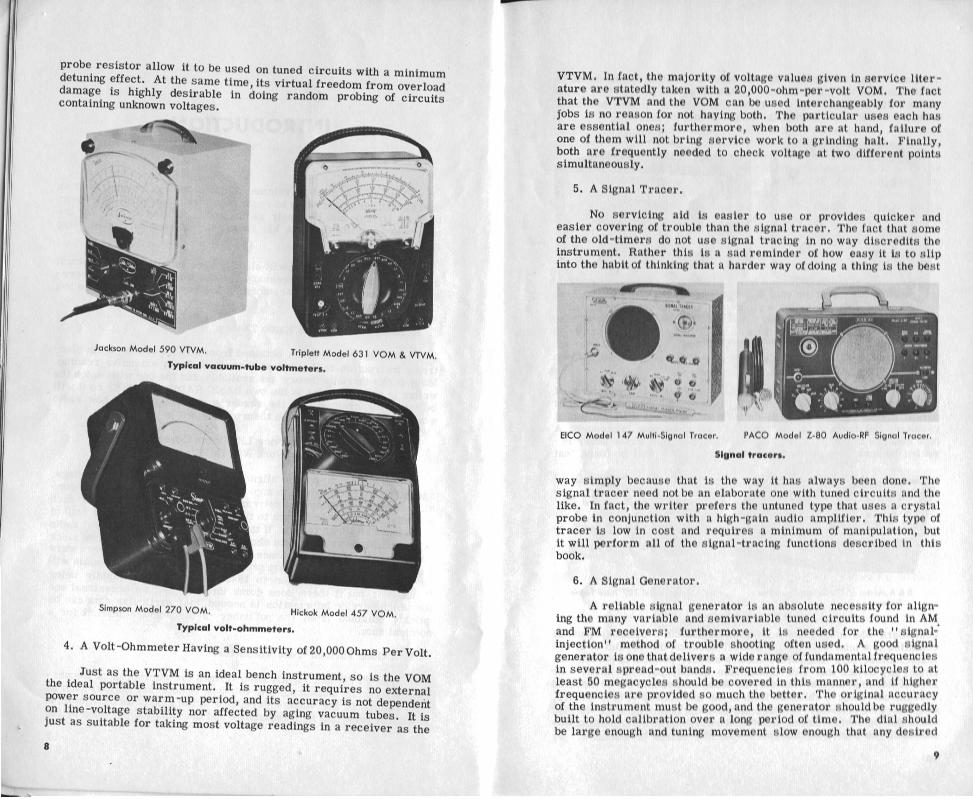

frequency may be easily set with accuracy. High output should be available; yet the shielding and attenuator should premit this output to be reduced smoothly and gradually to a v e r y low minimum. Internal audio modulation of the output should be provided.
Precision Model E-200-C Signal-Mark- RCA Model WR-490 RF Signal Gen- ing Generator. erator.
Signal generators.
7. A Tube Tester.
A service technician might get by without this instrument, if he had sufficient stock of tubes and the time to substitute new ones one at a time in each socket of every set and note if improvement resulted; but that certainly would be a time-wasting procedure. A tube checker is much faster and will spot marginal cases never r e - vealed by such a crude method. Furthermore, it will be found that
-7
50 Tube and
C-
Transistor B & K Model 6. Tester.
Typical tube testers.
Seco Model 107 Tube '
/
Tester.
customers who may doubt a service technician1 s opinion about the condition of a tube will accept without question the verdict of a tube tester. Since tube sales represent a sizable portion of Service in- come, any device that aids those sales quickly pays for itself. One note of warning, though: the service technicianshould not be infected with the customer1 s childlike faith in the infallibility of tube testers, even the best of them. On ra re occasions a tube will show up and check all right in the tester but will not work in the set. Keeping this possibility in mind will often save a lot of time and trouble.
8. An Isolation Transformer.
A voltage-adjusting isolationtransformer is not merely a safety device; it is actually a service instrument. The fact that it protects the service technician from a possible fatal shock when he is working on hot-chassis receivers certainly makes it a must for the service shop. It will be found that when such a receiver is isolated from the line, the signal-generator and meter connections can be made to the set without observing the special precautions and hum-reducing measures which are necessary when the transformer is not used. If by adjusting the line voltage applied to the set one is able to simulate a wide range of conditions that may be found in the home, one can uncover troubles that cannot be found in any other way.
9. An Adequate Stock of Replacement Parts.
Of course, after you have found a defective part in a se t you will need a new part to replace it; but it may surprise you to know how often you willneed new parts tolocate a defective unit. It has already been pointed out that occasionally a tube tester will fail to reveal a defective tube, but substituting a new tube will immediately spotlight the trouble. In the same way doubtful capacitors are often quickly checked by bridging them with new capacitors, IF transformers a re
Adjust-A-Volt variable transformer.
tacked into a circuit in plHce of a suspected unit, and noisy resistors are unmasked by clipping new resistors in their place. Many times part substitution is the quickest and most practical way to locate
trouble, but to use this method a good stock of standard replacement items must be on hand.
10. A Good Set of Hand Tools.
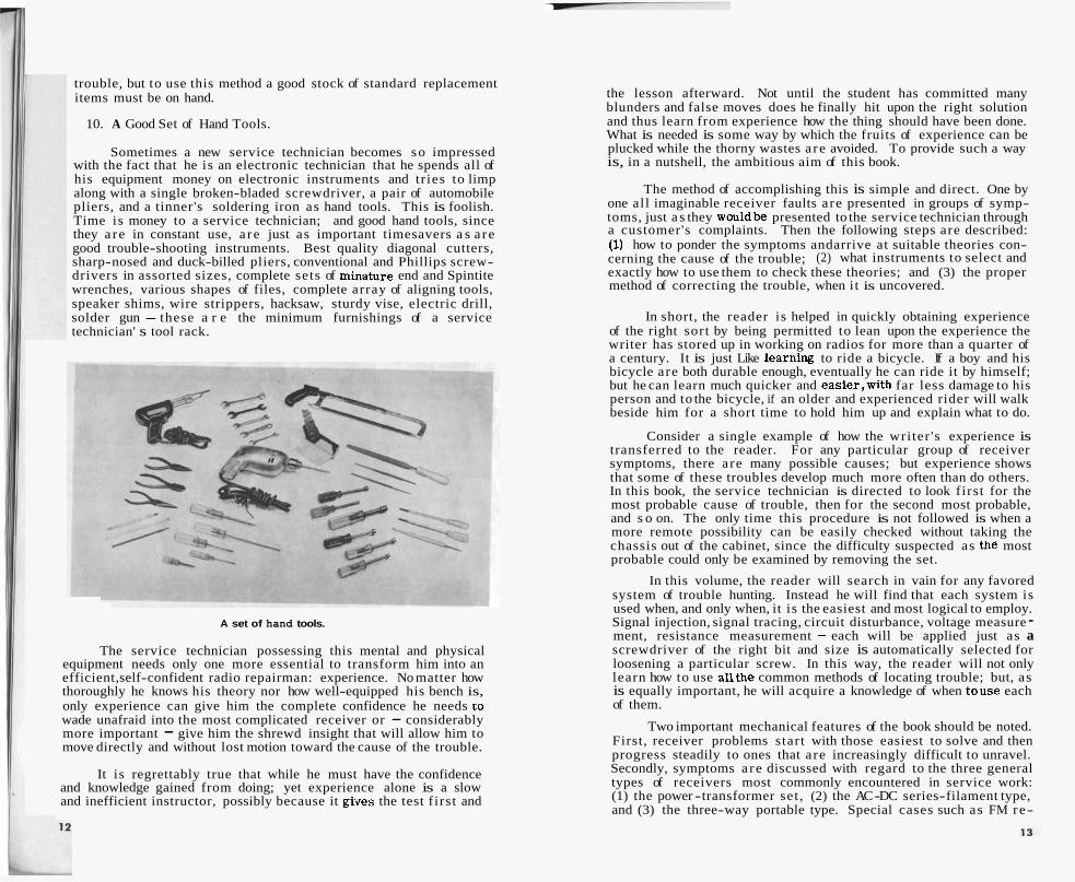
Sometimes a new service technician becomes so impressed with the fact that he is an electronic technician that he spends all of his equipment money on electronic instruments and tr ies to limp along with a single broken-bladed screwdriver, a pair of automobile pliers, and a tinner's soldering iron as hand tools. This is foolish. Time is money to a service technician; and good hand tools, since they a re in constant use, a re just as important timesavers a s a re good trouble-shooting instruments. Best quality diagonal cutters, sharp-nosed and duck-billed pliers, conventional and Phillips screw- drivers in assorted sizes, complete sets of minature end and Spintite wrenches, various shapes of files, complete array of aligning tools, speaker shims, wire strippers, hacksaw, sturdy vise, electric drill, solder gun - these a r e the minimum furnishings of a service technician' s tool rack.
A set of hand tools.
The service technician possessing this mental and physical equipment needs only one more essential to transform him into an efficient, self-confident radio repairman: experience. No matter how thoroughly he knows his theory nor how well-equipped his bench is, only experience can give him the complete confidence he needs to wade unafraid into the most complicated receiver or - considerably more important - give him the shrewd insight that will allow him to move directly and without lost motion toward the cause of the trouble.
It is regrettably true that while he must have the confidence and knowledge gained from doing; yet experience alone is a slow and inefficient instructor, possibly because it gives the test f irst and
the lesson afterward. Not until the student has committed many blunders and false moves does he finally hit upon the right solution and thus learn from experience how the thing should have been done. What is needed is some way by which the fruits of experience can be plucked while the thorny wastes a re avoided. To provide such a way is, in a nutshell, the ambitious aim of this book.
The method of accomplishing this is simple and direct. One by one all imaginable receiver faults are presented in groups of symp- toms, just a s they wouldbe presented to the service technician through a customer's complaints. Then the following steps are described: (I) how to ponder the symptoms andarrive at suitable theories con- cerning the cause of the trouble; (2) what instruments to select and exactly how to use them to check these theories; and (3) the proper method of correcting the trouble, when i t is uncovered.
In short, the reader is helped in quickly obtaining experience of the right sort by being permitted to lean upon the experience the writer has stored up in working on radios for more than a quarter of a century. It is just Like learning to ride a bicycle. If a boy and his bicycle are both durable enough, eventually he can ride it by himself; but he can learn much quicker and easier,with far less damage to his person and to the bicycle, if an older and experienced rider will walk beside him for a short time to hold him up and explain what to do.
Consider a single example of how the writer 's experience is transferred to the reader. For any particular group of receiver symptoms, there are many possible causes; but experience shows that some of these troubles develop much more often than do others. In this book, the service technician is directed to look first for the most probable cause of trouble, then for the second most probable, and s o on. The only time this procedure is not followed is when a more remote possibility can be easily checked without taking the chassis out of the cabinet, since the difficulty suspected as the most probable could only be examined by removing the set.
In this volume, the reader will search in vain for any favored system of trouble hunting. Instead he will find that each system is used when, and only when, it is the easiest and most logical to employ. Signal injection, signal tracing, circuit disturbance, voltage measure - ment, resistance measurement - each will be applied just as a screwdriver of the right bit and size is automatically selected for loosening a particular screw. In this way, the reader will not only learn how to use all the common methods of locating trouble; but, as is equally important, he will acquire a knowledge of when touse each of them.
Two important mechanical features of the book should be noted. First, receiver problems start with those easiest to solve and then progress steadily to ones that are increasingly difficult to unravel. Secondly, symptoms a re discussed with regard to the three general types of receivers most commonly encountered in service work: (1) the power -transformer set , (2) the AC -DC series-filament type, and (3) the three-way portable type. Special cases such as FM re-

ceivers , all-wave se t s , t ransis tor receivers , auto radios, and storage-battery portables a r e taken up in separate chapters at the back of the book. This arrangement makes easy reading, a minimum of repetition, and a concentration of help where it will do the most good.
The volume is intended t o be read, f i r s t , f rom cover to cover . A great deal of practical general information has been sprinkled throughout the chapters dealing with specific kinds of receiver failures. The bonus bits of information have been inserted at points where their introduction seems the most logical and natural, and they will be absorbed effortlessly by one who goes through the book f rom the beginning.
After the book has been read, it i s not intended to be placed on a shelf to collect dust. Instead i t is a reference work designed to be consulted whenever a service technician runs into a problem he cannot readily solve by himself. Between its covers is a so r t of electronic Rogues' gallery containing symptomatic pictures of about every kind of receiver failure imaginable. When the service techni- cian finds himself baffled, he has merely to match up the symptoms in the book and then follow the step-by-step procedure for ferreting out the trouble.
As time goes by he will need to consult the book less and less often, for i ts teachings will become part of his growing fund of know- ledge. Never forget that al l the important part of service work is done a s Hercule Poirot puts it , " In the little gray cel ls of the mind." As soon a s the student can be taught tothink like a service technician, he i s a service technician - and not before! Any form of instruction that merely tells what to do but fai ls to teach how to think will only produce an automaton that cannot function without constant direction.
Finally, this book has not been written in a sober and dignified style. Will Durant says, "Wisdom is not wise if it s c a r e s away merriment," and to this the wri ter breathes a hearty "Amen1 " He has had fun writing the book, and he devoutly hopes the reader will have fun reading it.
QUESTIONS
1. Give two sources of basic knowledge of radio theory. 2. Describe service l i terature needed by the beginning radio techni-
cian. 3 . Name four essential test instruments. 4. What two important functions a r e provided by a voltage-adjusting
isolation t ransformer? 5. List several important tools for doing good service work.
6. Explain why a n adequate supply of replacement parts is needed in locating radio trouble.
SECTION I
No Reception

CHAPTER 1
The Dead Set
Service technicians a r e fond of comparing their work with that performed by members of the medical profession, and there i s a strong resemblance between the diagnostic techniques required in the two fields. Radio servicing and doctoring, however, a r e poles apart in this basic respect : the patient that even the best doctor will admit he cannot help i s the dead one; while for the se rv ice technician, the deader a s e t the eas ie r it ordinarily is to repa i r . That i s why we shal l s t a r t with a s e t that i s completely devoid of life; one that emi t s no sound from the speaker , no light f rom the dial lamps o r g lass tubes, no warmth from the metal tubes - in shor t , a receiver that i s " stone cold dead in the market."
The f i r s t thing to do i s to look at the circui t diagram. The significant symptom is lack of filament current ; s o notice if the s e t i s a t rans former type, an AC-DC rece iver , o r a so-called three-way portable. In each of these cases , the filaments a r e supplied in a different manner.
THE TRANSFORMER SET
Fig. 1-1 shows a typical AC-input circui t fo r a t ransformer type of receiver . Notice the tube filaments a r e heated from two separa te secondary windings on the power t ransformer. L3 supplies the filament of the rect i f ier ; L4 provides cur ren t for all other f i la- ments, including those of the pilot lamps. Sometimes a rect i f ier with an indirectly heated cathode, such a s a 6x5, i s used; and then L3 i s omitted and the rect i f ier filament i s fed f r o m the same secondary that supplies the other tube filaments.
The fuse i s shown in dotted outline to indicate it may o r may not be present . Unless the se t i s large and expensive, the chances a r e a fuse will not be found. At any rate, check the diagram ra ther

No Reception The Dead Set
than rely on being able to s ee a fuse-holder along the r ea r of the chassis. Occasionally fuses a r e tucked away in unsuspected places.
With the VOM se t to a middle range of the ohmmeter, turn on the receiver and touch the test leads to the two prongs of the power plug of the receiver. If you get a reading of only a few ohms you can be su r e that the plug, the line cord , the switch, the primary of the power t ransformer , and the fuse if any a r e not defective. If the ohm- meter shows infinite resistance, which is much more likely, you will know there i s an open circuit in one of these items or in the connections between them.
PILOT LAMP TUBE FILAULNTS
Fig. 1 - 1. AC input circuit for a transformer type receiver.
In the latter event, use the ohmmeter to check the continuity of the fuse if one is present. If it i s open, replace it with a good unit of the specified value. If that blows out shortly after the s e t is turned on, the se t i s drawing excessive current. The reason for this can be determined by following the instructions given in Chapter 5 which deals with that symptom.
If the fuse i s good o r i s not present and no continuity is obtained from one plug prong to the other, use insulation-piercing test prods (the wri ter prefers the type with smal l chucks that use replaceable phono-needle tips) and the ohmmeter to test the continuity of each conductor of the line cord between the plug prong to which i t i s con- nected and the point where the cord en te rs the chassis . If a break is indicated in one o r both conductors, employ the sharp-pointed prods to make connection with each conductor about three inches away from the plug. Continuity through the primary winding of the t ransformer from these points indicates a break in the line cord a t the most commonly worn part, which is next to the plug where the cord i s subjected to maximum flexing. In that event, the end of the cord should be cut off about t h r eeo r four inches back of the plug and a new plug installed; or , if the cord shows any signs of deterioration, the whole thing should be renewed.
If no continuity can be observed, even though the prods pierce the line-cord insulation right next to the chassis ; then the trouble must lie inside the set , and the chassis will have to be removed. If it is not immediately obvious how the receiver comes out,look at the service notes for instructions on chassis removal. Doing s o will often save time and prevent damage t o the se t o r cabinet.
Once the set is out, use the ohmmeter to check for continuity across the tie-point ends of the line cord, making su r e that the s e t switch i s s t i l l turned on and that the line cord i s not plugged in. If an open circuit is st i l l indicated, the switch should be suspected. Check ac ro s s i t s terminals with the ohmmeter. If adead short i sno t indicated, the switch is bad and must be replaced. If it is mounted on the r e a r of a volume o r tone control, it i s a good practice to r e - place both the switch and the control with the proper replacement items given in the service data. Since such a control represents one of the few moving and consequently wearing par t s in a receiver, it will probably be ready fo r replacement anyway.
If checking the switch indicates that it is good, then the only remaining possibility is that the t ransformer primary is open. Be- cause of the relatively heavy wire used in this winding, open circui ts in it a r e seldom found - but they can happen! On two occasions the wri ter found leads of the primary broken just a t the point where they entered the shell of the t ransformer. These probably broke because of excessive flexing in manufacture, shipping, o r installation. If a break inthe winding cannotbe found at a point where it can be readily repaired, the whole t ransformer must be replaced.
Let us go back and suppose that on our f i r s t test we found a proper resis tance indicated from one plug prong to the other. That means that the primary circuit of the t ransformer must be in order and that there must be something wrong in the secondary circui ts feeding the tube filaments o r with the tubes themselves. For all of the tubes tobe burned out at once i s placing a terr i f ic s t ra in on coinci- dence; but it has been known to happen when the s e t was s truck by lightning, when it was accidentally plugged into a 220-volt outlet, o r when the owner did a little experimental tube "swapping" on his own before bringing in the se t for repair . Check a couple of tubes in the tube tester . The rectifier and output tubes a r e two good choices. If the rect i f ier is of the direct -heating type, this will provide one tube fed by each filament secondary winding. Incidentally, look at the service data or the tube-position chart t o make s u r e these tubes a r e in their proper sockets. Failure to notice that tubes have been switched in their sockets has put many a gray hair in the service technician' s thatch.
If the tubes light in the tube checker but not in their proper sockets in the se t , the chassis must come out. Remove the rectifier
,tube, and lay it aside s o that high DC voltages will not be present in
19
No Reception
the set. Plug in the receiver and turnit on. Use your VOM set to the ten-volt AC range in order to check whether dr not a filament volt- age is present across the proper filament terminals of all the sockets in the se t except the rectifier socket. If no Eilament voltage is found at any of these sockets, locate the ends 01 the filament winding coming out of the power transformer, and measure the voltage right where these leads are soldered to tie-points. If voltage is found (and it should be), use the AC voltmeter to trace along the leads from that point until you locate the place where either a broken wire or a poor connection is preventing the currentfrom reaching the tube filaments; then repair that break.
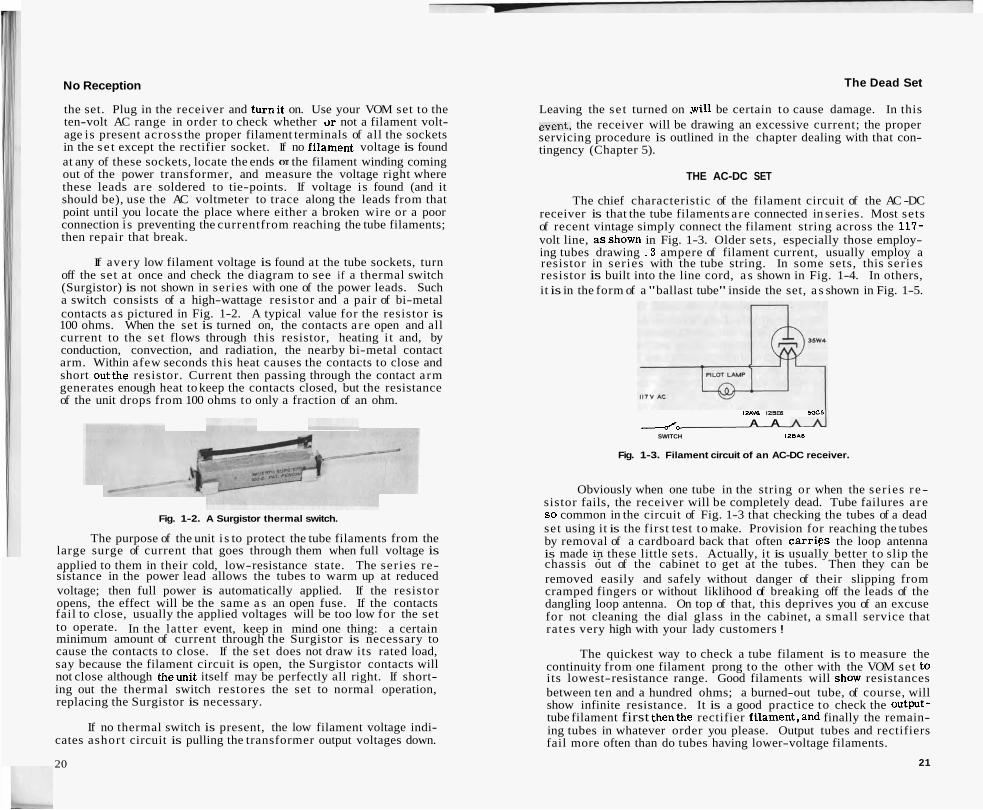
If avery low filament voltage is found at the tube sockets, turn off the set at once and check the diagram to see if a thermal switch (Surgistor) is not shown in series with one of the power leads. Such a switch consists of a high-wattage resistor and a pair of bi-metal contacts a s pictured in Fig. 1-2. A typical value for the resistor is 100 ohms. When the set is turned on, the contacts a re open and all current to the set flows through this resistor, heating i t and, by conduction, convection, and radiation, the nearby bi-metal contact arm. Within afew seconds this heat causes the contacts to close and short outthe resistor. Current then passing through the contact arm generates enough heat to keep the contacts closed, but the resistance of the unit drops from 100 ohms to only a fraction of an ohm.
Fig. 1-2. A Surgistor thermal switch.
The purpose of the unit i s to protect the tube filaments from the large surge of current that goes through them when full voltage is applied to them in their cold, low-resistance state. The series re- sistance in the power lead allows the tubes to warm up at reduced voltage; then full power is automatically applied. If the resistor opens, the effect will be the same a s an open fuse. If the contacts fail to close, usually the applied voltages will be too low for the set to operate. In the latter event, keep in mind one thing: a certain minimum amount of current through the Surgistor is necessary to cause the contacts to close. If the set does not draw its rated load, say because the filament circuit is open, the Surgistor contacts will not close although theunit itself may be perfectly all right. If short- ing out the thermal switch restores the set to normal operation, replacing the Surgistor is necessary.
If no thermal switch is present, the low filament voltage indi- cates ashort circuit is pulling the transformer output voltages down.
20
The Dead Set
Leaving the se t turned on .will be certain to cause damage. In this event, the receiver will be drawing an excessive current; the proper servicing procedure is outlined in the chapter dealing with that con- tingency (Chapter 5).
THE AC-DC SET
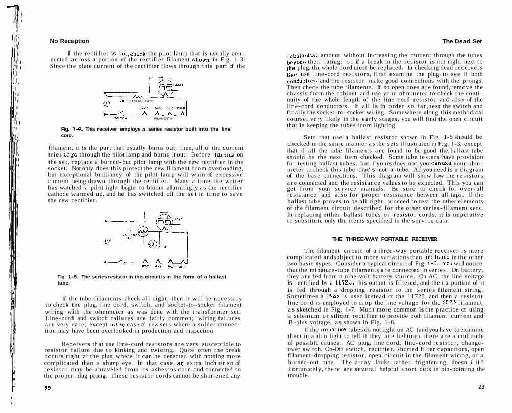
The chief characteristic of the filament circuit of the AC -DC receiver is that the tube filaments are connected in series. Most sets of recent vintage simply connect the filament string across the 117- volt line, asshown in Fig. 1-3. Older sets, especially those employ- ing tubes drawing . 3 ampere of filament current, usually employ a resistor in series with the tube string. In some sets, this series resistor is built into the line cord, a s shown in Fig. 1-4. In others, it is in the form of a "ballast tube" inside the set, a s shown in Fig. 1-5.
IZAVB 12- M C S
J* A A SWITCH l2BAE
Fig. 1-3. Filament circuit of an AC-DC receiver.
Obviously when one tube in the string or when the series r e- sistor fails, the receiver will be completely dead. Tube failures are SO common in the circuit of Fig. 1-3 that checking the tubes of a dead set using it is the first test to make. Provision for reaching the tubes by removal of a cardboard back that often carrigs the loop antenna is made in these little sets. Actually, it is usually better to slip the chassis out of the cabinet to get at the tubes. Then they can be removed easily and safely without danger of their slipping from cramped fingers or without liklihood of breaking off the leads of the dangling loop antenna. On top of that, this deprives you of an excuse for not cleaning the dial glass in the cabinet, a small service that rates very high with your lady customers !
The quickest way to check a tube filament is to measure the continuity from one filament prong to the other with the VOM set to its lowest-resistance range. Good filaments will show resistances between ten and a hundred ohms; a burned-out tube, of course, will show infinite resistance. It is a good practice to check the output- tube filament first thenthe rectifier filament,and finally the remain- ing tubes in whatever order you please. Output tubes and rectifiers fail more often than do tubes having lower-voltage filaments.
21
I NO Reception The Dead Set
If the rectifier is out,check the pilot lamp that is usually con- nected across a portion of the rectifier filament shown in Fig. 1-3. Since the plate current of the rectifier flows through this part of the
1 1 7 V LINE CORD RESISTOR
-J SWITCW FILAMENTS
Fig. 1-4. This receiver employs a series resistor built into the line cord.
filament, it is the part that usually burns out; then, all of the current t r ies togo through the pilot lamp and burns it out. Before t u rn~ng on the s e t , replace a burned-out pilot lamp with the new rectifier in the socket. Not only does this protect the new filament f rom overloading, but exceptional brilliancy of the pilot lamp will warn of excessive current being drawn through the rectifier. Many a time the wri ter has watched a pilot light begin to bloom alarmingly a s the rectifier cathode warmed up, and he has switched off the s e t in time to save the new rectifier.
Fig. 1-5. The series resistor in this circuit i s in the form of a ballast tube.
If the tube filaments check al l right, then it will be necessary to check the plug, line cord, switch, and socket-to-socket filament wiring with the ohmmeter a s was done with the transformer set. Line-cord and switch failures a r e fairly common; wiring failures a r e very r a r e , except inthe case of new sets where a solder connec- tion may have been overlooked in production and inspection.
Receivers that use line-cord res i s tors a r e very susceptible to resis tor failure due t o kinking and twisting. Quite often the break occurs right a t the plug where it can be detected with nothing more complicated than a sharp eye. In that case, an extra inch o r s o of res i s tor may be unraveled from its asbestos core and connected t o the proper plug prong. These res i s tor cords cannot be shortened any
substantial amount without increasing the current through the tubes beyond their rating; s o if a break in the resistor is not right next to the plug, the whole cord must be replaced. In checking dead receivers that use line-cord res i s tors , f i r s t examine the plug to see if both conductors and the resistor make good connections with the prongs. Then check the tube filaments. If no open ones a r e found, remove the chassis from the cabinet and use your ohmmeter t o check the conti- nuity of the whole length of the line-cord resistor and also of the line-cord conductors. If al l is in order s o f a r , test the switch and finally the socket -to-socket wiring. Somewhere along this methodical course, very likely in the early stages, you will find the open circuit that i s keeping the tubes f rom lighting.
Sets that use a ballast resis tor shown in Fig. 1-5 should be checked in the same manner a s the sets illustrated in Fig. 1-3, except that if al l the tube filaments a r e found to be good the ballast tube should be the next item checked. Some tube tes te rs have provision for testing ballast tubes; but if yours does not, you canuse your ohm- meter to check this tube -that' s -not -a -tube. All you need is a diagram of the base connections. This diagram will show how the res i s tors a r e connected and the resistance values to be expected. This you can get from your service manuals. Be sure to check for over-all resistance and also for proper resistance between all taps. If the ballast tube proves to be all right, proceed to test the other elements of the filament circuit described for the other series-filament se t s . In replacing either ballast tubes or resis tor cords, it is imperative t o substitute only the i tems specified in the service data.
THE THREE-WAY PORTABLE RECEIVER
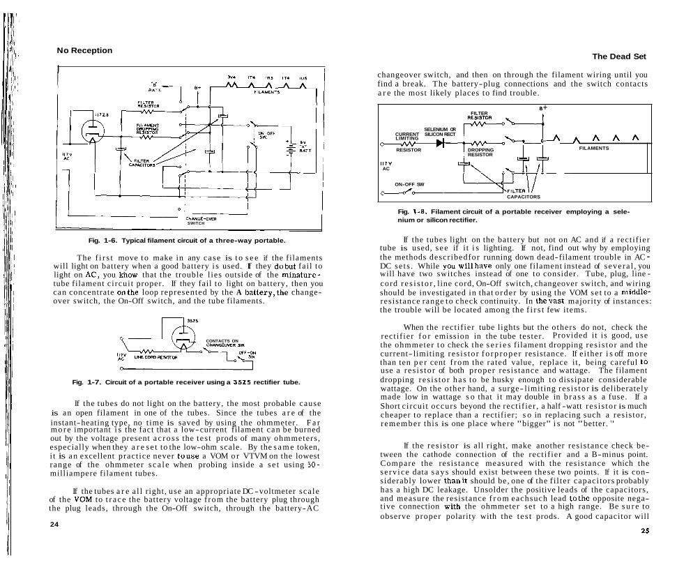
The filament circuit of a three-way portable receiver i s more complicated andsubject to more variations than arefound in the other two basic types. Consider a typical circuit of Fig. 1-6. Y-ou will notice that the minature-tube filaments a r e connected in series . On battery, they a r e fed from a nine-volt battery source. On AC, the line voltage is rectified by a 11723, this output is filtered, and then a portion of it is fed through a dropping resistor to the s e r i e s filament string. Sometimes a 3 5 2 5 is used instead of the 11723, and then a resis tor line cord is employed t o drop the line voltage for the 3 5 2 5 filament, a s sketched in Fig. 1-7. Much more common is the practice of using a selenium o r silicon rect if ier to provide both filament current and B-plus voltage, a s shown in Fig. 1-8.
If the minature tubes do not light on AC (and you have to examine them in a dim light to tell i f they a r e lighting), there a r e a multitude of possible causes: AC plug, line cord, line-cord res i s tor , change- over switch, On-Off switch, rectifier, shorted filter capacitors, open filament-dropping res i s tor , open circuit in the filament wiring, o r a burned-out tube. The a r r ay looks rather frightening, doesn' t it '? Fortunately, there a r e several helpful short cuts in pin-pointing the trouble.
23
No Reception
I I
- , I CHANGE-OYER SWITCH
Fig. 1-6. Typical filament circuit of a three-way portable.
The f i r s t move t o make in any case is t o s e e if the filaments will light on battery when a good battery i s used. If they dobut fai l to light on AC, you know that the trouble l ies outside of the minature- tube filament circui t proper. If they fail to light on battery, then you can concentrate onthe loop represented by the A battery,the change- over switch, the On-Off switch, and the tube filaments.
CONTACTS ON CHANGEOVER SW,
';y LINE tORD REY¶rn
Fig. 1-7. Circuit of a portable receiver using a 3525 rectifier tube.
If the tubes do not light on the battery, the most probable cause is an open filament in one of the tubes. Since the tubes a r e of the instant-heating type, no t ime is saved by using the ohmmeter. F a r m o r e important i s the fact that a low-current filament can be burned out by the voltage present a c r o s s the t es t prods of many ohmmeters , especially when they a r e s e t to the low-ohm scale. By the s a m e token, i t is a n excellent pract ice never t o u s e a VOM o r VTVM on the lowest range of the ohmmeter s c a l e when probing inside a s e t using 50- milliampere filament tubes.
If the tubes a r e a l l right, use an appropriate DC -voltmeter sca le of the VOM to t r a c e the battery voltage f rom the battery plug through the plug leads, through the On-Off switch, through the battery-AC
24
The Dead Set
changeover switch, and then on through the filament wiring until you find a break. The battery-plug connections and the switch contacts a r e the most likely places to find trouble.
B + FILTER
I I
SELENIUM OR CURRENT SILICON RECT LIMITING d \ ; : A A A A RESISTOR DROPPING FILAMENTS
RESISTOR
117V AC
ON-OFF SW
d o CAPACITORS
Fig. 1-8. Filament circuit of a portable receiver employing a sele- nium or silicon rectifier.
If the tubes light on the battery but not on AC and if a rect i f ier tube is used, s e e if i t i s lighting. If not, find out why by employing the methods describedfor running down dead-filament trouble in AC - DC se t s . While you willhave only one filament instead of severa l , you will have two switches instead of one to consider. Tube, plug, line - cord r e s i s t o r , l ine cord, On-Off switch, changeover switch, and wiring should be investigated in that o rder by using the VOM se t to a middle- resis tance range t o check continuity. In thevast majority of instances: the trouble will be located among the f i r s t few items.
When the rect i f ier tube lights but the others do not, check the rect i f ier f o r emission in the tube tester . Provided i t is good, use the ohmmeter t o check the s e r i e s filament dropping res i s to r and the current- limiting res i s to r f o r p r o p e r resistance. If e i ther i s off more than ten p e r cent f rom the rated value, replace it , being careful to use a res i s to r of both proper resis tance and wattage. The filament dropping res i s to r h a s to be husky enough to dissipate considerable wattage. On the other hand, a surge- limiting res i s to r is deliberately made low in wattage s o that i t may double in b r a s s a s a fuse. If a Short c i rcui t occurs beyond the rect i f ier , a half -watt res i s to r is much cheaper to replace than a rectifier; s o in replacing such a resis tor , r emember this is one place where "bigger" i s not "better. "
If the res i s to r is all right, make another resis tance check be- tween the cathode connection of the rect i f ier and a B-minus point. Compare the resis tance measured with the resis tance which the se rv ice data s a y s should exist between these two points. If it is con- siderably lower thani t should be, one of the f i l ter capaci tors probably has a high DC leakage. Unsolder the positive leads of the capacitors, and measure the resis tance f r o m eachsuch lead to the opposite nega- tive connection with the ohmmeter se t to a high range. Be s u r e to observe proper polarity with the tes t prods. A good capacitor will
I
No Reception
show a heavy "kick" of the. ohmmeter when the test leads are 11l .b~
connected, and then the pointer will gradually settle back to a reading of several thousand ohms or even megohms. Lack of this charging " kickff indicates an open-circuit capacitor. A final reading of only a few dozen ohms signifies a leaky capacitor. Capacitors showing either symptom should be replaced, for leaky capacitors will par- tially short-circuit the output of the rectifier. An open-circuit input capacitor, the one directly across the rectifier outplt, will cause the output voltage to be about thirty per cent lower than it should be. A quick check of a suspected open-circuit input filter capacitor can be made by bridging it with a known good capacitor while observing the voltage output of the rectifier. If this brings up the voltage sub- stantially, the capacitor is open.
The bad capacitor usually will be one of two or more units housed in a single can or cardboard container. The best policy is to replace the whole filter-capacitor assembly. In, the first place, there is often no room to install an outboard capacitor beneath the crowded chassis of a portable set; secondly, since one unit has yielded up the ghost, the life expectancy of the others which are of the same age is not good. Once more the.service manuals should be consulted for a replacement that will fit both mechanically and electrically.
In dealing with a se t using a selenium rectifier in which the tubes do not light, the one different item is the rectifier itself. Selenium rectifiers are subject to two kinds of failure: shorting and decreased output. When a rectifier shorts, all you need to detect the condition is a nose - a not-too-sensitive nose at that. A shorted rectifier will overheat, the paint will peel, and it will throw off a strong odor of rotten e ~ - - '
put rectif is condit
Tf f ? V A r \
' iers siml .ion is ha ... .
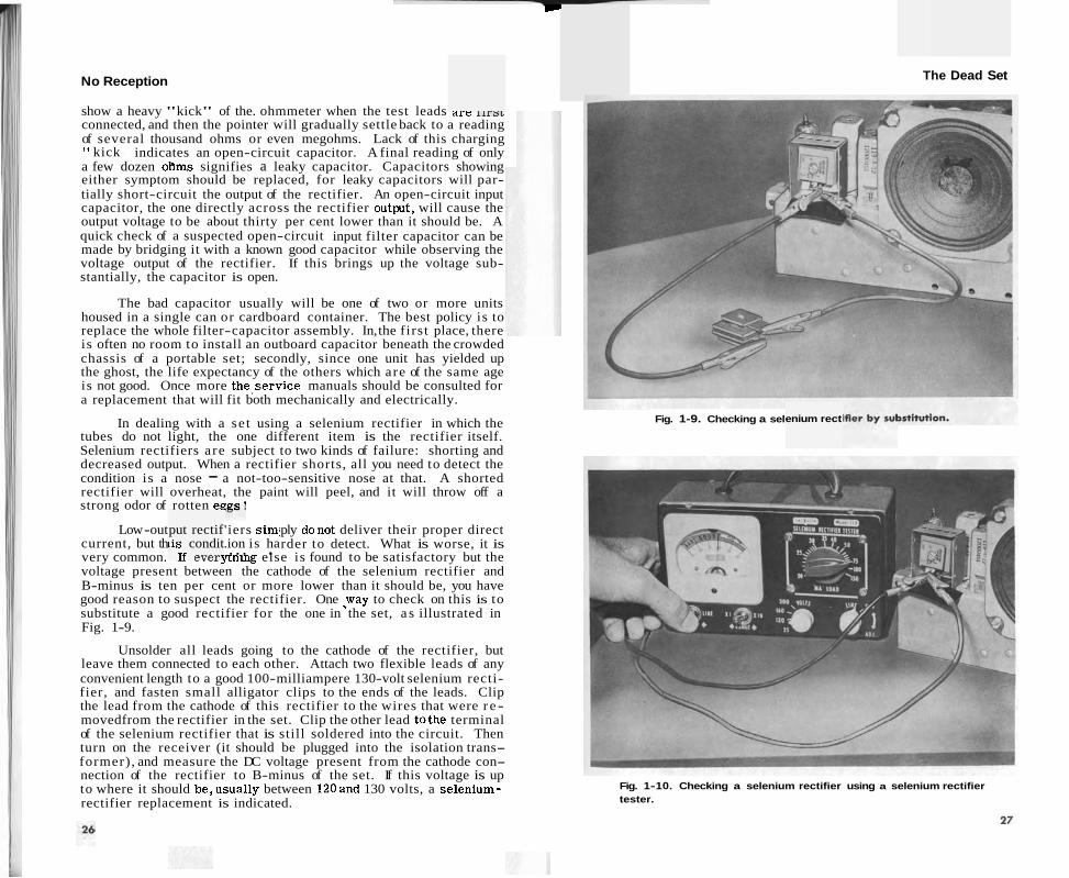
Low -out ply donot deliver their proper direct current, but th rder to detect. What is worse, it is very common. - - . -- flnlng else is found to be satisfactory but the voltage present between the cathode of the selenium rectifier and B-minus is ten per cent or more lower than it should be, you have good reason to suspect the rectifier. One .way to check on this is to substitute a good rectifier for the one in the set, a s illustrated in Fig. 1-9.
Unsolder all leads going to the cathode of the rectifier, but leave them connected to each other. Attach two flexible leads of any convenient length to a good 100-milliampere 130-volt selenium recti- fier, and fasten small alligator clips to the ends of the leads. Clip the lead from the cathode of this rectifier to the wires that were r e - movedfrom the rectifier in the set. Clip the other lead tothe terminal of the selenium rectifier that is still soldered into the circuit. Then turn on the receiver (it should be plugged into the isolation trans- former), and measure the DC voltage present from the cathode con- nection of the rectifier to B-minus of the set. If this voltage is up to where it should be,usually between 120and 130 volts, a selenium- rectifier replacement is indicated.
The Dead Set
Fig. 1-9. Checking a sel enium rect
Fig. 1-10. Checking a selenium rectifier using a selenium rectifier tester.

No Reception
The condition of the selenium rect i f ier can a l so be checked by using a selenium-rectifier t es te r . Disconnect the leads f r o m one terminal of the selenium rect i f ier and connect the test leads of the tester . After setting the controls on the tes te r , a direct reading is obtained which is indicative of the condition of the rectifier. Fig. 1-10 i l lustrates this par t icular test. If the unit t es t s weak o r bad,
I
I obviously it should be replaced.
Silicon rect i f iers usually do not give visual o r olfactory evidence when they go bad; but since they a r e ordinarily held in a clip o r de- tachable pigtail holders, the easiest way to check one of them is to s l ip aun i t known to be good in i t s place and s e e if this res to res nor- mal voltage and filament current . Always inspect the current- limiting res i s to r before trying a new rectifier. If it looks a s though it has been too hot, check for low resis tance between the output of the rect i f ier and B-minus, such a s might be caused by a leaky o r shorted f i l ter capacitor, before trying a new rectifier. Otherwise you may have the painful experience of seeing your new rect i f ier blow, too.
This completes the chapter on s e t s in which the filaments will not light. Using the techniques outlined and expanding them to e m - brace any minor variations of the basic circui ts discussed, the se rv ice technician should be able to impart quickly the fundamental spark of life t o any s e t he may encounter.
QUESTIONS
1. What i s the significant symptom of a "dead" s e t ? 2. What instrument i s used to check the continuity through fuses,
switches, and line c o r d s ? 3. Describe the operation and purpose of a "Surgistor. " 4. What i s the important difference between the way tube filaments
a r e connected in a t rans former s e t and the way they a r e connected in an AC-DC rece iver?
5. When a burned-out rect i f ier is replaced in an AC-DC set , why should a burned-out pilot lamp a l so be replaced before the se t is turned on?
6. Why i s it inadvisable to use the ohmmeter to check the filaments of tubes used in three-way portable rece ivers?
7. How can an ohmmeter be used to make a rough check of the con- dition of a f i l ter capaci tor?
8. Name two possible causes of low voltage being measured a t the output of a selenium rect i f ier in a three-way portable.
9. What i s a quick and simple way to check a silicon rec t i f i e r?
CHAPTER 2
Tubes Light But No Sound
A c u s t o m e r ' s description of receiver symptoms can r a r e l y be taken literally. He may ca l l a ,hum a whistle, a whistle a howl, and a howl a kind of vibration. Moreover, he may tel l you his s e t is " dead a s a doornail," when a glance through fhe r e a r of the cabinet will show that a l l the tubes and dial lamps glow with lively brilliance a s soon a s the s e t is turned on.
The morbid description probably a r i s e s f r o m the fact that he has used his e a r instead of his eye for diagnosis; for no sound, not even normal low hum, can be heard f r o m the speaker though the e a r may be pressed against the gr i l le cloth. With such a s e t , a little reflection will te l l you that the trouble must l i e in the speaker , the output t ransformer, the output stage, o r the power supply for that stage. In a normal s e t , the smal l amount of 60- or 120-cycle ripple present in the DC plate current of the output tube willalways produce a perceptible amount of hum in the speaker. In a s e t with a well- f i l tered power supply, this hum may be low enough to be more fel t than heard; but it will be there unless something is wrong with the aforementioned output -circuit components.
THE TRANSFORMER SET
The t rans former s e t is usually housed in a console cabinet. In such c a s e s the speaker and often the output t rans former mounted on the speaker in the lower cabinet a r e easily accessible f o r testing without removing the chassis . So a r e the output and rect i f ier tubes, and they should receive your f i r s t attention. Make s u r e these tubes, located by consulting the tube-position chart in the cabinet o r your se rv ice l i terature, a r e lit .
If they a r e g lass , you c a n tel l by just looking at them; but while you a r e looking, notice a couple of other things. See if the s c r e e n g r i d of the output tube is glowing with a r e d or white heat. If i t is, the s e t may have an output t ransformer with an open primary winding that has removed the voltage f rom the plate of the tube and is allowing the s c r e e n to absorb the en t i re electron output of the cathode, thus Causing it to overheat. Note, too, if the rect i f ier seems to be filled with a blue or pink glowing gas. Such a gassy rect i f ier will often lightup but willput out no current a t all. If the plates of the rect i f ier s t a r t glowing a cher ry red , the s e t should be switched off a t once,for this indicates a short c i rcui t somewhere in the receiver . A gassy tube should be replaced with a good one. The procedure for locating
29
No Reception Tubes Light But No Sound
and correcting a power-supply short circuit is outlined in a later chapter.
In the case of tubes with metal envelopes, these envelopes will become noticeably warm to the touch after the se t has been turned on for a minute or s o if the filaments a r e lighting. (Yes, you use every sense you have in radio servicing and could use a couple morel) If the output or rectifier tube does not light, you a r e in luck; for r e - placing the dead tube with a good one will probably clear up the trouble. If they do light, next turn your attention to the speaker and output transformer.
l a+ I Fig. 2-1. Basic output circuits commonly used.
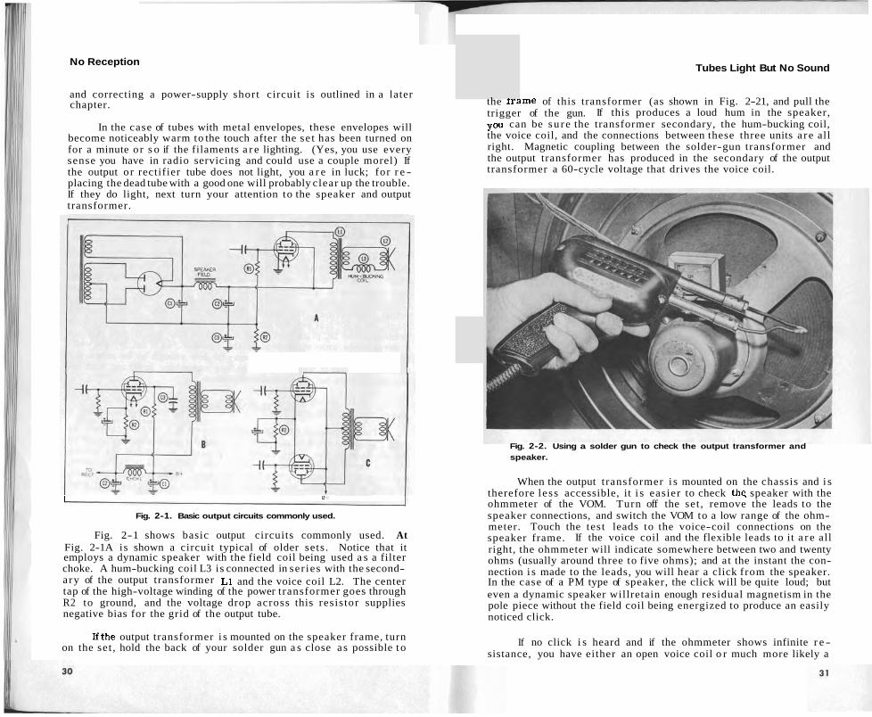
Fig. 2-1 shows basic output circuits commonly used. At Fig. 2-1A is shown a circuit typical of older sets . Notice that it employs a dynamic speaker with the field coil being used a s a filter choke. A hum-bucking coil L3 is connected in ser ies with the second- ary of the output transformer L1 and the voice coil L2. The center tap of the high-voltage winding of the power transformer goes through R2 to ground, and the voltage drop across this resistor supplies negative bias for the grid of the output tube.
Ifthe output transformer i s mounted on the speaker frame, turn on the set , hold the back of your solder gun a s close a s possible t o
the l rame of this transformer (as shown in Fig. 2-21, and pull the trigger of the gun. If this produces a loud hum in the speaker, you can be su re the transformer secondary, the hum-bucking coil, the voice coil, and the connections between these three units a r e all right. Magnetic coupling between the solder-gun transformer and the output transformer has produced in the secondary of the output transformer a 60-cycle voltage that drives the voice coil.
Fig. 2-2. Using a solder gun to check the output transformer and speaker.
When the output t ransformer i s mounted on the chassis and i s therefore less accessible, it i s easier to check the speaker with the ohmmeter of the VOM. Turn off the set , remove the leads to the speaker connections, and switch the VOM to a low range of the ohm- meter. Touch the test leads to the voice-coil connections on the speaker frame. If the voice coil and the flexible leads to it a r e all right, the ohmmeter will indicate somewhere between two and twenty ohms (usually around three to five ohms); and at the instant the con- nection i s made to the leads, you will hear a click from the speaker. In the case of a PM type of speaker, the click will be quite loud; but even a dynamic speaker willretain enough residual magnetism in the pole piece without the field coil being energized to produce an easily noticed click.
If no click i s heard and if the ohmmeter shows infinite r e - sistance, you have either an open voice coil o r much more likely a

Tubes Light But No Sound
tube. If no such click is heard, the trouble is perhaps in the speaker voice coil o r i t s leads, and you should proceed a s in the c a s e of s imi la r trouble in a t rans former set. If the click is heard, the trouble must l i e in an improper sc reen , cathode, o r control-grid voltage. When one of these voltages deviates f romtha t indicated in the se rv ice data, study the diagram and t r y t o imagine a par t fa i lure that could produce the improper reading. Suspect capaci tors f i r s t , r e s i s t o r s second, and other par t s third. Use your ohmmeter t o determine whether o r not you have guessed right. If not, continue investigation until the trouble is located by considering the causes in o rder f r o m the most logical to the least. Since you will be dealing only with the smal l portion of the circui t immediately connected with the output tube, this should not take long.
Speaker fai lures a r e common in these s m a l l s e t s ; output- t ransformer fai lures a r e l e s s so. Many t imes a capacitor wil lshort- c i rcui t and destroy a rect i f ier ; so , if a rect i f ier tube lights but del ivers no output, it is a good idea t o check the resis tance between the rect i f ier cathode and B-minus before turning on the receiver with a new tube in the socket. If this res i s tance is abnormally low, locate the shorted component with the ohmmeter and replace it. Out- side of these special considerations, proceed just a s you would in dealing with a t rans former set.
THE THREE-WAY PORTABLE RECEIVER
It i s difficult to be s u r e whether the tubes a r e lighting and whether there is sound f r o m the speaker in these se t s ; because the tube filaments a r e not easily seen, the normal hum f r o m the speaker whenthe s e t i s operating onAC i s notgreat , and there is no hum when it is operating on battery. Some sound, though, can usually be heard, even i f it i s only the crackling of a warming-up filament. If the tubes have been tested and a r e lighting and if no sound can be heard on ei ther AC o r battery, the s e t will undoubtedly have t o be removed f r o m the cabinet for fur ther checking.
Check the speaker with ei ther the solder-gun technique de- scr ibed previously o r with the ohmmeter. If you depend upon the click f rom the speaker when the ohmmeter leads a r e touched t o the voice-coil terminals ra ther than upon the actual ohmmeter reading, it will not be necessary t o unsolder t h e leads from the output t ransformer. This leaves the secondary of the t rans former in paral- lel with the voice coil, and you will get a low-resistance reading through the secondary even though the voice coil is open; but you willnot hear the click unless the voice coil is operating satisfactorily.
Providing the speaker i s a l l right, you will next have to make voltage checks on the output tube; and in the majority of these mini- ature s e t s , this is a ticklish job. The socket connections a r e hard t o reach and usually a r e concealed by other parts ; the re is scarce ly
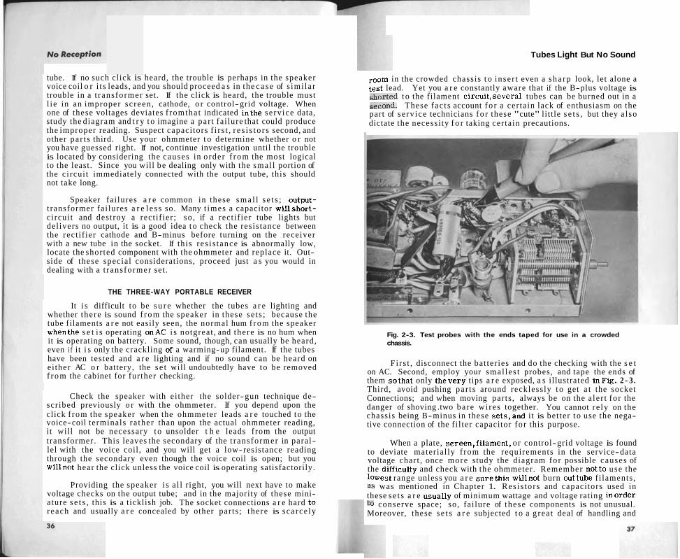
room in the crowded chassis t o inser t even a s h a r p look, let alone a test lead. Yet you a r e constantly aware that if the B-plus voltage is shorted t o the filament circui t ,several tubes can be burned out in a second. These fac t s account f o r a cer tain lack of enthusiasm on the part of se rv ice technicians f o r these "cute" little s e t s , but they a l so dictate the necessi ty f o r taking cer tain precautions.
Fig. 2-3. Test probes with the ends taped for use in a crowded chassis.
Fi rs t , disconnect the bat ter ies and do the checking with the s e t on AC. Second, employ your smal les t probes, and tape the ends of them so tha t only thevery tips a r e exposed, a s illustrated inFig. 2-3. Third, avoid pushing par t s around recklessly t o get a t the socket Connections; and when moving parts , always be on the a le r t fo r the danger of shoving .two bare wi res together. You cannot re ly on the chassis being B-minus in these se t s ,and it is bet ter t o use the nega- tive connection of the f i l ter capacitor fo r this purpose.
When a plate, screen,f i lament , o r control-grid voltage is found to deviate mater ial ly f rom the requirements in the service-data voltage chart , once more study the diagram for possible causes of the difficulty and check with the ohmmeter. Remember not to use the lowest range unless you a r e s u r e t h i s willnot burn outtube f i laments , a s was mentioned in Chapter 1. Res i s to rs and capaci tors used in these s e t s a r e usually of minimum wattage and voltage rating inorder to conserve space; so, fa i lure of these components is not unusual. Moreover, these s e t s a r e subjected t o a g rea t deal of handling and

No Reception
often receive thumps and ja r s that produce shor t c i rcu i t s , broken connections, o r s imi la r difficulties in the crowded wiring. Tube prongs that do not make good connections with their sockets a r e also common, and many of these s e t s can be brought t o life simply by wiggling one of the miniature tubes in i t s socket. Replacing a de- fective socket is a major , l as t- resor t task; but often a sharp- pointed sc ra tch awl can be used t o manipulate loose and bent prong
Fig. 2-4. A scratch awl being used to straighten bent prong holders on a miniature tube socket.
holders into proper shape and position for making good contact with the pins. See Fig. 2-4.
If you will follow the procedures outlined, you should have no difficulty in quickly locating the trouble in a s e t that has light without sound.
QUESTIONS
1. When the tubes light but not the slightest sound i s heard from the speaker , where do you expect to find the trouble?
2. \K. hat does a red-hot sc reen of an output tube usually indicate in a dead s e t ?
3. Describe how a solder gun can be used to make a quick check of speaker voice coil, output t rans former secondary, and connections between them.
Tubes Light But No Sound
4. How can a receiver not even plugged in s t i l l present a threat t o an -. ohmmeter?
5. When replacing a rect i f ier tube in an AC-DC rece iver that lights but del ivers no output, what precautions should f i r s t be taken'?
6. Describe precautions t o be used in working on three-way portables to avoid burning out tubes by accidentally short-circuiting wires .
7. How can loose tube socket prong holders often be repa i red?
Only Slight Hum Is Heard
CHAPTER 3
Only Slighr Hum Is Heard
A s e t that emi t s only a low hum f rom the speaker does not provide very definite c lues t o the cause of trouble. The hum shows the voice coil is not open; and if the s e t uses a PM speaker , it a lso indicates cur ren t is passing through the pr imary of the output t r a n s - former . With a dynamic speaker , normal AC ripple in the field coi l cur ren t will often produce noticeable hum f rom the cone, even though the pr imary of the output t rans former is open.
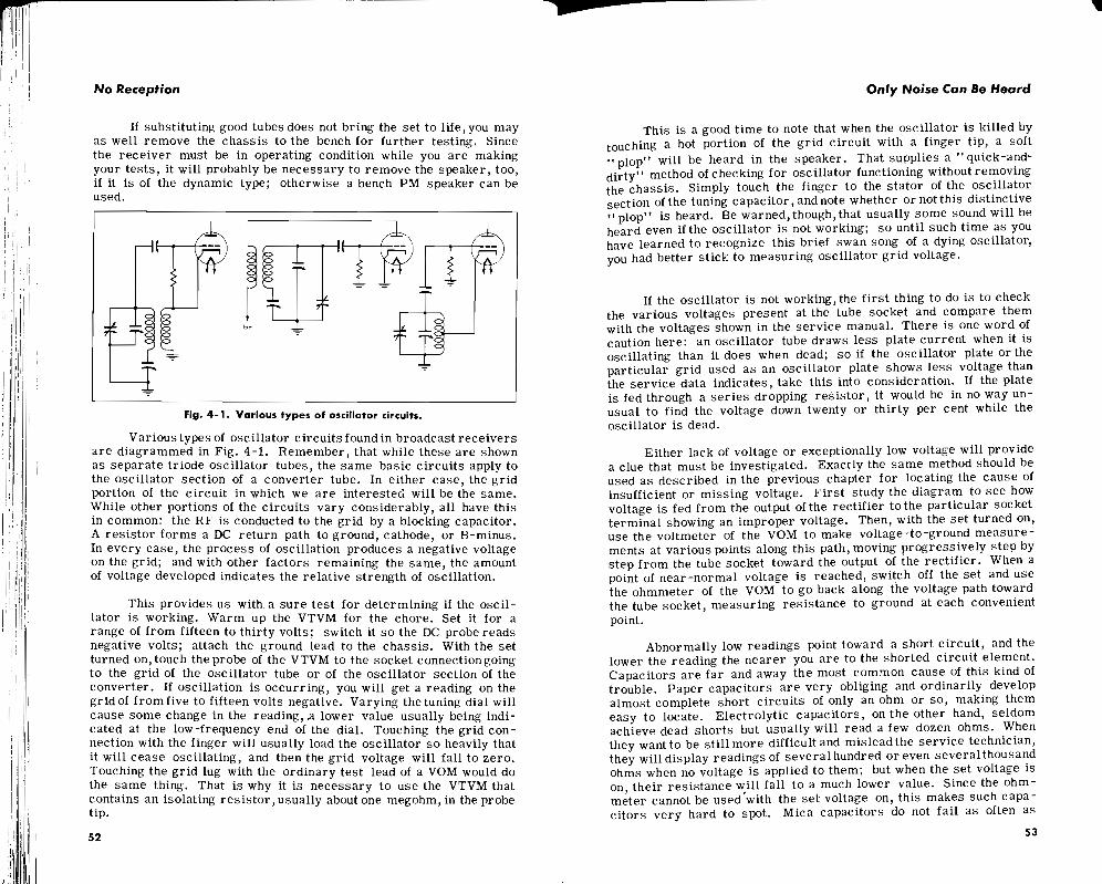
Actually what is not heard f r o m the speaker is more helpful than the lone sound emitted. Lack of station reception establishes that the signal i s being lost somewhere ahead of the speaker. Lack of character is t ic oscillator h i ss indicates that e i ther the oscillator is not working o r the trouble l ies in the mixer o r some stage following the mixer. On the other hand, even with the oscillator not working, we should s t i l l be able to hear s tat ic and other random noise passing directly through a mixer that is functioning normally; s o we a r e reasonably safe in ruling out the oscillator and in concluding that the trouble must lie in the mixer , IF, detector, audio, o r output stages.
That s t i l l leaves most of the circui ts of the s e t open t o suspicion. In such a case, where the observed symptoms do not localize the probable cause of the trouble sufficiently,we must employ a trouble- shooting technique that will supply this specific information.
THE TRANSFORMER SET
Nothing i r k s the wr i te r quite s o much a s t o spend considerable t ime and effort removing a chass i s that is difficult t o remove f rom a console cabinet only t o find that the trouble was a shorted tube or some other minor trouble that could have been cor rec ted without taking out the chass i s a t all. That is why he f i rmly believes inmaking a l l possible t es t s t o discover the cause of trouble before the chassis is pulled.
Make s u r e that the se t is switched toRADIO ra ther than PHONO and that the bandswitch,if any, i s s e t t o the broadcast band. Turn the volume control wide open. Before leaving the s e t onfor any length of t ime, notice if the rect i f ier plates a r e turning red o r if the re is an
later. If nothing of this nature is observed, the s e t can safely be left on while you proceed with your circui t disturbance testing.
In this type of t es t , the s tat ic operating conditions of a tube circuit a r e abruptly changed. One way of doing this is t o drop the plate cur ren t suddenly to z e r o by pulling the tube f r o m i t s socket. Another way i s t o produce a sudden change ingrid potential by touch- ing the gr id connection with a finger o r a screwdriver bit. Such a n act will always produce a momentary change in g r id potential a t the instant of contact. Furthermore, the body absorbs a ce r ta in amount of AC 60-cycle cur ren t f r o m the atmosphere. When a finger is touched to a g r id lead with a high impedance between it and ground, this absorbed AC is sufficient t o produce a peak-to-peak gr id swing of two o r th ree volts.
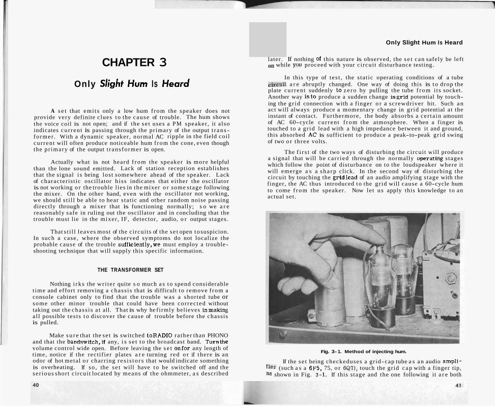
The f i r s t of the two ways of disturbing the circui t will produce a signal that will be ca r r ied through the normally operatilig s tages which follow the point of disturbance on to the loudspeaker where it will emerge a s a s h a r p click. In the second way of disturbing the circuit by touching the gr id lead of an audio amplifying s tage with the finger, the AC thus introduced t o the g r id will cause a 60-cycle hum to come f r o m the speaker. Now let us apply this knowledge t o an actual set .
Fig. 3- 1. Method of injecting hum.
odor of hot metal o r charr ing r e s i s t o r s that would indicate something If the s e t being checkeduses a gr id-cap tube a s a n audio ampli- is overheating. If so , the s e t will have t o be switched off and the f i e r (such a s a 6F5, 75, o r 6Q7), touch the gr id c a p with a finger tip, se r ious short c i rcui t located by means of the ohmmeter, a s described a s shown in Fig. 3 -1. If this s tage and the one following it a r e both
No Reception
operating properly, a loudhum wil lbe heard f rom the speaker. When the audio amplifier is a single-ended type, such a s a 6SF5,or 6SQ7, pull i t f rom i t s socket and listen for a click in the speaker. Absence of such a click indicates that e i ther the tube itself is not drawing plate cur ren t o r e l se there is something wrong in the output stage following it.
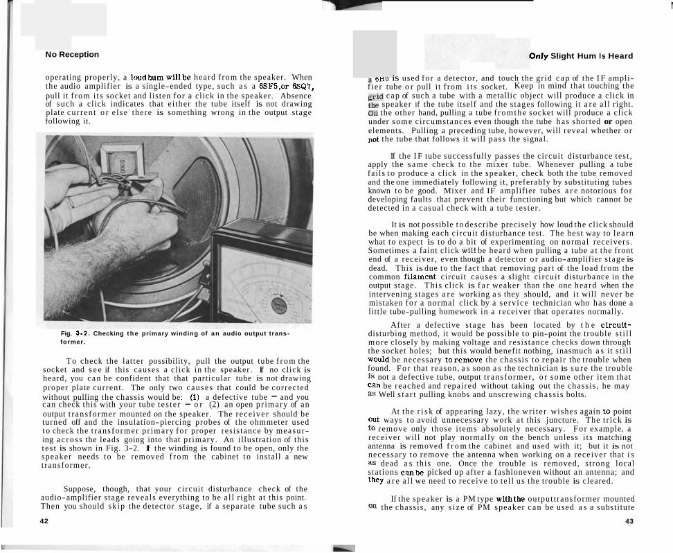
Fig. 3-2. Checking t h e primary winding of an audio output trans- former.
To check the la t ter possibility, pull the output tube f r o m the socket and s e e if this causes a cl ick in the speaker. If no click is heard, you can be confident that that particular tube is not drawing proper plate current . The only two causes that could be corrected without pulling the chassis would be: (1) a defective tube - and you can check this with your tube tes te r - o r (2) an open pr imary of an output t rans former mounted on the speaker. The rece iver should be turned off and the insulation-piercing probes of the ohmmeter used t o check the t rans former p r imary for proper resis tance by measur- ing a c r o s s the leads going into that pr imary. An illustration of this t es t is shown in Fig. 3-2. If the winding is found t o be open, only the speaker needs t o be removed f r o m the cabinet t o install a new transformer.
Suppose, though, that your circui t disturbance check of the audio-amplifier s tage reveals everything to be a l l right a t this point. Then you should sk ip the detector s tage, if a separate tube such a s
42
Dnly Slight Hum Is Heard
a sno is used for a detector, and touch the gr id c a p of the I F ampli- f ie r tube o r pull i t f rom i t s socket. Keep in mind that touching the grid cap of such a tube with a metallic object will produce a click in the speaker if the tube itself and the s tages following it a r e a l l right. On the other hand, pulling a tube f r o m t h e socket will produce a click under some circumstances even though the tube has shorted or open elements. Pulling a preceding tube, however, will reveal whether o r not the tube that follows it will pass the signal.
If the I F tube successfully passes the circui t disturbance test , apply the s a m e check t o the mixer tube. Whenever pulling a tube fai ls t o produce a click in the speaker , check both the tube removed and the one immediately following it , preferably by substituting tubes known to be good. Mixer and IF amplifier tubes a r e notorious fo r developing faults that prevent their functioning but which cannot be detected in a casual check with a tube tester .
It is not possible t o describe precisely how loud the click should be when making each circui t disturbance test. The best way to l ea rn what to expect is to do a bit of experimenting on normal receivers . Sometimes a faint click will be heard when pulling a tube a t the front end of a receiver , even though a detector o r audio-amplifier s tage is dead. This is due to the fact that removing par t of the load from the common filament circuit causes a slight c ircui t disturbance in the output stage. This click is f a r weaker than the one heard when the intervening s tages a r e working a s they should, and i t will never be mistaken f o r a normal click by a se rv ice technician who has done a little tube-pulling homework in a receiver that operates normally.
After a defective s tage has been located by t h e circui t - disturbing method, it would be possible t o pin-point the trouble s t i l l more closely by making voltage and resis tance checks down through the socket holes; but this would benefit nothing, inasmuch a s it s t i l l would be necessary to remove the chassis t o repa i r the trouble when found. F o r that reason, a s soon a s the technician is s u r e the trouble is not a defective tube, output t rans former , o r some other i tem that can be reached and repaired without taking out the chassis , he may a s Well s t a r t pulling knobs and unscrewing chass i s bolts.
At the r i s k of appearing lazy, the wr i te r wishes again t o point Out ways t o avoid unnecessary work a t this juncture. The t r i ck is to remove only those i tems absolutely necessary. F o r example, a receiver will not play normally on the bench unless i t s matching antenna is removed f r o m the cabinet and used with it; but it is not necessary t o remove the antenna when working on a receiver that i s a s dead a s this one. Once the trouble is removed, s t rong local stations canbe picked up af ter a fashioneven without an antenna; and they a r e a l l we need t o receive t o t e l l us the trouble is cleared.
If the speaker is a PM type withthe output transformer mounted On the chassis , any s i z e of PM speaker can be used a s a substitute

No Reception
while the chass i s is on the bench. Of course, if a dynamic speaker is employed, it must be connected to the chass i s when the s e t is turned on.
Many t imes, a s is shown in Fig. 3-3, it will be found that with- out having to disconnect the speaker leads o r even the leads t o the loop antenna the chass i s can be s l id out and turned with the bottom side up on a low stool o r bench placed directly behind the cabinet. Necessary trouble shooting with the VOM or VTVM canbe performed
Fig. 3-3. Chassis removed from cabinet without disconnecting an- tenna and speaker leads.
and repa i r s made with the chass i s in this position almost a s easily a s if i t were on the bench. T ime saved in not having to remove and replace the speaker and loop antenna; to disconnect wi res running t o phono pickup, motor, and remote pilot lamps; o r to res tap le wi res that have been torn loose f rom their proper position in the cabinet can be applied to repair ing another set . You must never forget that t o a se rv ice technician t ime i s money.
With a speaker connected and the volume turned t o maximum, the f i r s t move i s t o check the plate voltage of the tube that failed t o respond to your circui t disturbance testing a s you progressed f r o m the speaker toward the front of the se t , circuitwise. If plate voltage is present but you fail t o hear a click a s you connect the voltmeter, the trouble l i es in the following stage; and you should t rans fe r your
Only Slight Hum Is Heard
,ttention t o it. If voltage is present a t the plate and a cl ick is heard, then the t roublemus t l ie within the s tage itself; and you should pro- ceed with fur ther t e s t s of s c r e e n , cathode, and grid potentials. When no voltage is present , there will be no click; then you may know that YOU have hit upon the trouble right away. All that remains to be done is to find out why no plate voltage i s present.
The circui t diagram of the particular setbeing tested should be constantly before you a s you make voltage checks; but for the purpose of our discussion, le t us assume that the typical voltage-distribution circuit of a t ransformer s e t shown i n Fig. 3-4 applies in the c a s e at hand. Suppose, too, that you heard no click when an output tube was
WTWT SCREENS PLATES OREENS RF MIXER IF RF MIXER IF
PLATE
Fig. 3-4. Typical voltage distribution circuit commonly used in a transformer set.
'pulled f rom i t s socket and that no plate voltage could be measured at the socket connection. Lack of plate voltage could resul t e i ther f rom an open pr imary winding on the output t rans former o r f r o m a shorted inputcapacitor C1. The quickest way todiscover which is the case is to check the voltage present a t the output of the rect i f ier . If normal o r higher voltage i s found a t this output, the t rans former winding must be open. The s e t can be switched off and the ohmmeter used between the rect i f ier output and the plate of the output tube to double-check this. In this particular case , you have a push-pull out- put stage, and fur ther resis tance checks shouldbe made t o determine if both halves of the p r imary a r e open. As mentioned before, this can happen.
If no voltage is present a t the output of the rec t i f i e r , t u r n off the s e t a t once and check with the ohmmeter f r o m the Output of the rectifier t o ground. If a low resis tance of only a few ohms is read, C1 is probably shorted. Cut it loose f rom the circui t and check it with the ohmmeter before replacing it. If C1 were actually shorted, you doubtless would have noticed before this that the rect i f ier and Power t rans former were becoming excessively hot; fo r a shor t c i r - cuit in this capacitor would throw a heavy load on both these parts .


No Reception Excessive Current Indication
the voltage drop across it and s o stops the overheating before it is destroyed. Keeping such a possibility in mind may save considerable time when checking for a low-resistance short circuit.
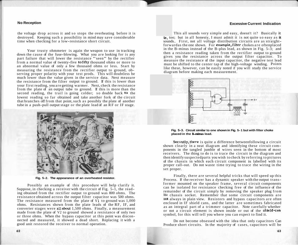
Your trusty ohmmeter i s again the weapon to use in tracking down the cause of the fuse-blowing. What you a r e looking for i s any part failure that will lower the resistance "seen" by the rectifier from a normal value of twenty-five tofifty thousand ohms or more to an abnormal value of only a few thousand ohms or less. Start by measuring the resistance from the rectifier output to ground, ob- serving proper polarity with your test prods. This will doubtless be much lower than the value given in the service data. Next measure the resistance from the filter output to ground. If this i s lower than your f irst reading, you a r e getting warmer. Next, check the resistance from the plate of an output tube to ground. If this i s more than the second reading, the t ra i l i s going colder; s o double back to the lowest reading so far obtained and take another fork of the circuit that branches off from that point, such a s possibly the plate of another tube in a push-pull output stage o r the plate lead of an R F or IF stage.
Fig. 5-2. The appearance of an overheated resistor.
Possibly an example of this procedure will help clarify it. Suppose, in checking a receiver with the circuit of Fig. 5-1, the read- ing obtained from the rectifier output to ground was 800 ohms. The resistance obtained across the output filter capacitor was 500 ohms. The resistance measured from the plate of V1 to ground was 1,000 ohms. Resistances shown from the plate leads of the RF, IF, and converter stages were allabout 1,500 ohms. Finally, a measurement made from the plate of V2 to ground showed a resistance of only two or three ohms. When the bypass capacitor at this point was discon- nected and measured, it showed a dead short. Replacing it with a good unit restored the receiver t o normal operation.
This all sounds very simple and easy, doesn't i t? Basically it is , too; but in all honesty, I must admit it i s not quite s o easy a s it sounds.. F i rs t , not al l voltage distribution circuits a r e a s straight- forwardas the one shown. For example,filter chokes a r e oftenplaced in the B-minus instead of the B-plus lead, a s shown in Fig. 5-3; and then a resistance reading taken from the rectifier output to ground gives you the resistance across the output filter capacitor. To measure the resistance of the input capacitor, the negative test lead must be shifted to the center tap of the high-voltage winding. Points like these, however, can be easily noted if you will study the service diagram before making each measurement.
Fig. 5-3. Circuit similar to one shown in Fig. 5- 1 but with filter choke placed in the 6-minus lead.
Secondly,there i s quite a difference betweenfollowing a circuit shown clearly in a neat diagram and identifying these circuit com- ponents in the tangled jumble of wires seen in the bottom of most receivers. The thing to do i s to trace the circuit in the diagram and then identify suspectedparts you wish to check by referr ing to pictures of the chassis in which each circuit component is labelled with i ts proper call-out. Do not waste time trying to trace the wiring in the se t proper.
Finally, there a r e several helpful t r icks that will speed up this Process. If the receiver has a dynamic speaker with the output t rans- former mounted on the speaker frame, several circuit components can be isolated for resistance checking free of the influence of the remainder of the circuit simply by removing the speaker plug f rom its chassis socket. Remember that some circuit components a r e not always in plain view. Resistors and bypass capacitors a r e often enclosed in IF shield cans, and the latter a r e sometimes fabricated a s an integral part of a t r immer capacitor. Note carefully whether or not a circuit element i s shown inside or out of the shield-can symbol, for this will tell you where you can expect to find it.
Do not become obsessed with the idea that only capacitors Can Produce short circuits. In the majority of cases, capacitors will be


No Reception
the rectifier become too hot. In this case, vour sense of smell will again tell you what has happened; and an educated nose is not needed. An overheated selenium rectifier throws off an effluvium that smells exactly like rotten eggs or a strong artesian-water odor raised to about the tenth power! Before replacing such a rectifier with a new one, make careful resistance checks to be sure a short circuit in the DC voltage distribution circuit has not brought on this condition.
When a silicon rectifier fails, i t almost invariable short cir- cuits. It quits acting like aself-respecting rectifier and behaves more like a piece of copper wire. This places raw AC on the polarized electrolytic filter capacitors, and the reverse voltage damages them quickly if the surge-limiting resistor does not give up first. The electronic Tinkers-to-Evers-to-Chance goes something like this: the silicon rectifier short circuits; the reverse voltage pushes a high damaging current through the electrolytic capacitors, causing them to heat and puncture; the heavy current burns the surge-limiting resistor in two. Always check the filter capacitors carefully before replacing a ~harredg-iimitin~resistor and a silicon rectifier. Many t e c h ~ i ~ u t o m a t i c a l l y replace the filtercapacito-r these conditions, and the practice is easy to defend.
Fig. 5-6. Measuring resistance in a three-way portable.
Excessive Current Jndication
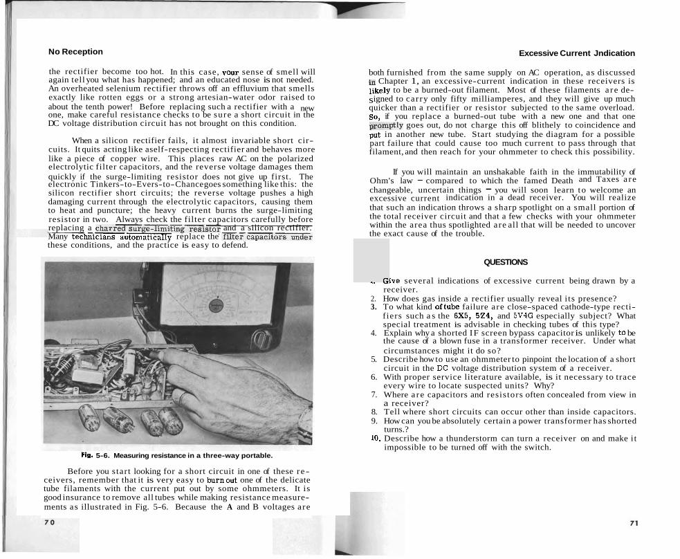
both furnished from the same supply on AC operation, as discussed in Chapter 1, an excessive-current indication in these receivers is likely to be a burned-out filament. Most of these filaments a re de- signed to carry only fifty milliamperes, and they will give up much quicker than a rectifier or resistor subjected to the same overload. SO, if you replace a burned-out tube with a new one and that one promptly goes out, do not charge this off blithely to coincidence and put in another new tube. Start studying the diagram for a possible part failure that could cause too much current to pass through that filament, and then reach for your ohmmeter to check this possibility.
If you will maintain an unshakable faith in the immutability of Ohm's law - compared to which the famed Death and Taxes a re changeable, uncertain things - you will soon learn to welcome an excessive current indication in a dead receiver. You will realize that such an indication throws a sharp spotlight on a small portion of the total receiver circuit and that a few checks with your ohmmeter within the area thus spotlighted are all that will be needed to uncover the exact cause of the trouble.
QUESTIONS
.. ,ive several indications of excessive current being drawn by a receiver.
2. How does gas inside a rectifier usually reveal i ts presence? 3. To what kind oftube failure are close-spaced cathode-type recti-
fiers such a s the 6x5, 524, and 5V4G especially subject? What special treatment is advisable in checking tubes of this type?
4. Explain why a shorted IF screen bypass capacitor is unlikely to be the cause of a blown fuse in a transformer receiver. Under what circumstances might it do so?
5. Describe how to use an ohmmeter to pinpoint the location of a short circuit in the DC voltage distribution system of a receiver.
6. With proper service literature available, is it necessary to trace every wire to locate suspected units? Why?
7. Where a re capacitors and resistors often concealed from view in a receiver?
8. Tell where short circuits can occur other than inside capacitors. 9. How can you be absolutely certain a power transformer has shorted
turns.? 10. Describe how a thunderstorm can turn a receiver on and make i t
impossible to be turned off with the switch.
Before you start looking for a short circuit in one of these r e- ceivers, remember that it is very easy to buinout one of the delicate tube filaments with the current put out by some ohmmeters. It is good insurance to remove all tubes while making resistance measure- ments as illustrated in Fig. 5-6. Because the A and B voltages are


~nsat is factor~ Reception Sets with Excessive Hum
is the 60-cycle output of a half-wave rectifier. The net result is that you get just about a s many hum complaints from transformer se ts as from any other.
As a first check, see ifthe volume-controlsetting influences the amount of hum. This will tell you if the hum is originating ahead of the control or behind it. Let's f irst assume that the hum stays about the same, no matter where the volume control is set, and that it is constant whether a signal is being received or not. These clues point at weak or open filter capacitors, but we want to be sure before we pull the chassis. It could be a case of a filament-to-cathode short in either an output tube or an audio amplifier. If the output stage is push-pull, there is a further possibility that only one-half of this stage is functioning.
To check this possibility, turn down the volume completely and remove one of the output tubes. If this tube has been working, the hum should increase. Replace the tube and pull its twin from the other socket of the push-pull stage. Again an increase in hum indi- cates the tube has been working. If the hum remains the same when one of the tubes is removed, you can be reasonably sure that the tube is not hnctioning; so t ry a new one in its place. If thisdoes not help there is a possibility that the output transformer is defective. To check it, leave the tube out of the socket and use your VOM to check for the presence of plate voltage at the plate pin on the socket. If none is present, it is likely one-half of the primary of the output transformer is open; and you can test for this possibility with your ohmmeter, as described in Chapter 2 of Section I. If plate voltage is present, the trouble must lie with some other part of the circuit of the tube in which case it would be necessary to remove the chassis.
If both outputtubes are found to be functioning, try new tubes in any audio-amplifier or phase-inverter stages between the volume control and the output stage. If this does not cure the hum, you may as well remove the chassis for further tests.
Open or weak filter capacitors a r e by far the most common cause of hum, and they should be suspected right from the beginning. Several different types of electrolytic capacitors a re shown in Fig. 6-1. The only reason for not checking them first is that doing so usually requires removing the chassis from the cabinet. An expert technician can often determine, just by listening, whether an input or outputfilter capacitor is open. 0rdinarily.the humis more severe when the input capacitor fails, and voice or music being received will be chopped up by the strong 120-cycle hum present. An accom- panying clue is the reduced DC voltage at all points.
When the output filter capacitor fails, the DC voltage is not affected and the hum is usually not so loud, although it is sufficiently loud to be objectionable. This sameoutput filter capacitor, however,
frequently doubles as both an R F and audio bypass; so when it fails there is, in addition to the increase in hum, a tendency of the set to motorboat o r oscillate. There may also be a sharp reduction in the ability of the set to reproduce low notes.
The quickest way to check for an open or weak filter capacitor is to bridge the suspected unit with another of like or greater voltage rating and of substantially the same capacity. As it is with every- thing else, there is a right and wrong way of doing this. The wrong way is to hold a cartridge type of electrolytic in the fingers and gin- gerly try to make the stiff wire leads contact the two points to which the c under suspicion is connected. In trying to perform this
Fig. 6- 1. Various types of electrolytic capacitors.
feat it is very easy to short-circuit something you shouldn't with the hard-to-manage wire leads and so damage the receiver, to injure the bridging capacitor by accidently applying reversed polarity volt- age to it, or to get a nasty shock from touching one of the bare wire leads in contact with a high-voltage point. A better and safer method is to use a pair of wedded Fahnstock and battery clips as shown in Fig. 6-2, in order to connect a pair of test leads to the bridging unit, making sure the red lead connects to the positive terminal of the capa- citor. Then these leads can be used to connect the bridging capa- citor across any two points with ease and safety.
Several points should be watched in employing this technique. For one thing, it is normal for the hum to lessen slightly when filter capacitors not at fault are bridged. When the capacitor really causing 77

Unsatisfactory Reception Sets with Excessive Hum
the trouble is paralleled with a good unit, the hum will almost entirely disappear, and corollary symptoms will clear up at the same time. Do not overlook the possibility that both input and output fiIter capa- citors may be open or weak. They could have failed in rapid suc- cession; or, if they are of the type having a common negative or common positive, a break may have occured along this common ele- ment. In such an event, bridging either unit will reduce the hum somewhat; but it will not disappear until both capacitors are bridged simultaneously with good replacements.
substitute, and you can bridge filter capacitors in a se t containing this fault until you grow a long gray beard without curing the hum. The proper check for such a condition is to cut the dual, triple, or
capacitor entirely loose from the circuit and then to use separate good capacitors in the place of each disconnected cell.
Once you have located a defective filter section, you must then make up your mind whether or not to replace all filter capacitors or just the bad unit. Common sense should dictate your decision. If the set has some years on it and if this is the first filter failure, it is best to replace all filter units, because there is the possibility that other aging capacitors will soon break down. On the other hand, if the set is comparatively new or if the filter capacitors have appar- ently been recently replaced, the chances are that the bad capacitor was defective from the start ; s o the other capacitors can be left in the circuit.
Inreplacing filter capacitors, keep the following points in mind. Follow service data specifications as to suitable replacements, if at all possible. When this cannot be done, be sure the replacements you select have voltage ratings at least equal to those of the original units and that they do not vary more than 20 per cent from the rated capa- cities. Do not connect a new capacitor across an old one left in the circuit; when possible, completely remove the old capacitor. Obvi- ously you cannot do this when you are replacing only one cell of a dual or triple unit, but you can and should cut loose the lead of the defective unit that is not common to the good unit or units still to be used. Do not hesitate to replace a can type electrolytic with a car- tridge unit of equal voltage rating and capacity, if this is more con- venient. Always try to keep any electrolytic capacitor as far away as possible from any heat-producing resistor or tube. Make sure that any capacitor you install is mechanically secure. Installing a capa- citor so that it dangles by its leads from the bottom of the chassis when the set is picked up is the mark of a sloppy workman.
Fig. 6-2. A safe method of bridging an electrolytic capacitor into a circuit.
If simple bridging of filter capacitors does not eliminate the hum, it is a good idea before actually cutting any wires to t ry to establish definitely whether o r not the trouble is insufficient filtering. To do this, measure the DC voltage across the output filter capacitor with your VTVM. Then measure the AC voltage present across these points with the same instrument. If the DC voltage is less than forty of fifty times greater than the AC voltage measured, filtering is in- sufficient; then you should proceed to explore some of the more unusual types of filter failures.
Suppose your checks with the VTVM reveal that the filtering of the power supply is satisfactory. Then the hum must be originating somewhere between the volume control which has no effect on the hum and the speaker which is loudly telling the world that hum is present. The question now becomes, " How canyou trace this hum to its source?"
Oneway is to use the signaltracer shown in Fig. 6-3. You want all the sound to come from the speaker of the signal tracer; there- fore, kill the set speaker by clipping a short piece of wire across the Voice-coil terminals. Fasten the ground lead of the audio probe of the signal tracer to the chassis, and touch the probe tip to the plate of the output tube. You will doubtless hear the hum distinctly. Move the probe to the grid of the output stage and see i f the hum is still Present. If it is , move the probe to the grid of the preceding audio
It could be that the filter choke or other unit used in place of the choke is defective. Check this element for proper resistance as given in the service data. Another nasty, rare, but not unheard-of thing with multicell capacitors is a short circuit from one cell to another. Such an occurrence effectively shorts out the filter choke or
stage and listen for hum again.
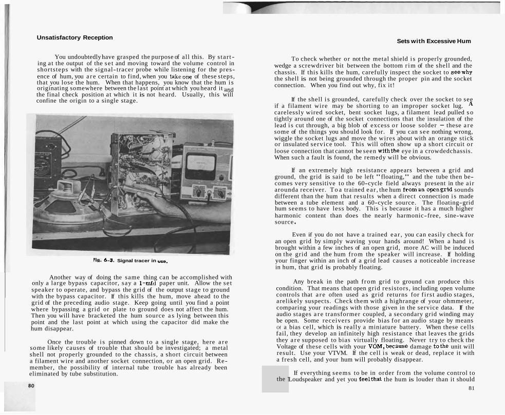
Unsatisfactory Reception
You undoubtedly have grasped the purpose of al l this. By s ta r t- ing a t the output of the s e t and moving toward the volume control in shortsteps with the signal- tracer probe while listening for the pres- ence of hum, you a r e certain to find, when you takeone of these steps, that you lose the hum. When that happens, you know that the hum i s originating somewhere between the last point at which you heard it and the final check position a t which i t is not heard. Usually, this will confine the origin to a single stage.
Fig. 6-3. Signal tracer in use.
Another way of doing the same thing can be accomplished with only a large bypass capacitor, say a 1-mfd paper unit. Allow the se t speaker to operate, and bypass the grid of the output stage to ground with the bypass capacitor. If this kills the hum, move ahead to the grid of the preceding audio stage. Keep going until you find a point where bypassing a grid or plate to ground does not affect the hum. Then you will have bracketed the hum source a s lying between this point and the last point at which using the capacitor did make the hum disappear.
Once the trouble i s pinned down to a single stage, here a r e some likely causes of trouble that should be investigated; a metal shell not properly grounded to the chassis, a short circuit between a filament wire and another socket connection, o r an open grid. Re- member, the possibility of internal tube trouble has already been eliminated by tube substitution.
Sets with Excessive Hum
To check whether or not the metal shield i s properly grounded, wedge a screwdriver bit between the bottom r im of the shell and the chassis. If this kills the hum, carefully inspect the socket to seewhy the shell is not being grounded through the proper pin and the socket connection. When you find out why, fix it!
If the shell i s grounded, carefully check over the socket to see if a filament wire may be shorting to an improper socket lug. A carelessly wired socket, bent socket lugs, a filament lead pulled s o tightly around one of the socket connections that the insulation of the lead i s cut through, a big blob of excess o r loose solder - these a r e some of the things you should look for. If you can see nothing wrong, wiggle the socket lugs and move the wires about with an orange stick or insulated service tool. This will often show up a short circuit o r loose connection that cannot be seen withthe eye in a crowdedchassis. When such a fault is found, the remedy will be obvious.
If an extremely high resistance appears between a grid and ground, the grid is said to be left "floating," and the tube then be- comes very sensitive to the 60-cycle field always present in the a i r arounda receiver. To a trained ea r , the hum f roman opengrid sounds different than the hum that results when a direct connection i s made between a tube element and a 60-cycle source. The floating-grid hum seems to have less body. This i s because it has a much higher harmonic content than does the nearly harmonic-free, sine-wave source .
Even if you do not have a trained ea r , you can easily check for an open grid by simply waving your hands around! When a hand i s brought within a few inches of an open grid, more AC will be induced on the grid and the hum from the speaker will increase. If holding your finger within an inch of a grid lead causes a noticeable increase in hum, that grid is probably floating.
Any break in the path f rom grid to ground can produce this condition. That means that open grid resistors , including open volume controls that a r e often used a s grid returns for f i r s t audio stages, arelikely suspects. Check them with a highrange of your ohmmeter, comparing your readings with those given in the service data. If the audio stages a r e transformer coupled, a secondary grid winding may be open. Some receivers provide bias for an audio stage by means Of a bias cell, which is really a miniature battery. When these cells fail, they develop an infinitely high resistance that leaves the grids they a r e supposed to bias virtually floating. Never t ry t o check the Voltage of these cells with your VOM,because damage tothe unit will result. Use your VTVM. If the cell i s weak or dead, replace it with a fresh cell, and your hum will probably disappear.
the ! If everything seems to be in order from the volume control to
Loudspeaker and yet you feelthat the hum is louder than it should 8 1

Unsatisfactory Reception Sets with Excessive Hum
place the AC voltage on a tube element where it does not belong, just a s you did with the t ransformer se t s . In addition, though,re- member that B-minus is not often connected t o the chass i s in these receivers; and whereas a short t o the chass i s in a t rans former r e - ceiver would cause the s e t to go dead, a short t o the chass i s in an AC-DC receiver will merely produce a loud hum.
THE THREE-WAY PORTABLE RECEIVER
Usually hum has t o b e ra ther bad in these s e t s t o elicit a com- plaint. Their s m a l l cabinets,and speakers do not encourage hum, and the owner ordinarily is not s o c r i t i ca l of performance. When hum does become a problem, f i l ter capaci tors a r e again the chief nffender.
Fig. 6-4. Tuning capacitor insulated from chassis.
A good example of a hum-producing short c i rcui t will be found in the case of a tuning capacitor that is insulated f rom the chass i s by rubber g rommets o r plastic insulators around t h e mounting sc rews a s shown in Fig. 6-4. If one of these grommets cu t s through - a s it often does f rom the constant s t r a i n imposed by a spring- loaded dial cord - the resul t will often be a loud hum that can be made to come and go by shifting the tuning-capacitor f rame. One case of intermittent hum was t raced by the wr i te r t o a metal dial pointer that occasionally touched the metallic foil dial face fastened t o the chassis and effectively shorted the tuning-capacitor f r a m e t o the chassis. Sometimes a dial lamp is mountedon the tuning-capacitor f r a m e and will produce a loud hum when a short circuit develops be- tween one of the conductors and the metal shel l of the socket.
These rece ivers suffer open gr id re tu rns , including broken antenna leads, just a s do t rans former s e t s ; and they a r e t racked down in the s a m e way. They a r e just a s subject to tunable hum when a line bypass capacitor opens up o r is blown apart by a lightning surge that comes in on the power line and jumps the switch.
Fig. 6-5. Portable receiver with loop antenna mounted in a hinged cover.
Do not bridge capaci tors in one of these s e t s with the receiver turned on. T o do s o is quite likely t o resul t ' in blown tubes. It is much sa fe r to tu rn off the s e t , connect the bridging capacitor t o the proper points, and then turn on the s e t again. Be s u r e t o discharge the bridging capacitor each t ime af ter removing it. Trying t o r e - connect i t in a charged condition can easily blow every tube filament in the radio. Again you should consult the wiring diagram t o be cer tain you a r e properly bridging the desired capacitors. DO not overlook the low-voltage, high-capacity f i l ter capaci tors ordinarily found a c r o s s the filament supply circui ts .
If a f i l ter unit is found t o b e bad, you will usually have no choice between replacing just that unit o r the whole capacitor of which it is just a part. There simply is not room in the crowded s m a l l chass i s fo r any outboard replacements. Follow instructions in the se rv ice data fo r selecting the replacement.
T r y new tubes. Tubes in these s e t s do not often develop faults Producing t r u e hum, but often a tube will produce a microphonic howl that a customer will descr ibe a s a hum.


Unsatisfactory Reception Set Does Not Separate Stations
heard a l l over the dial, the trouble is not one of alignment a t a l l but is caused by rectification in a stage, such a s an audio amplifier, that is not supposed t o be rectifying.
THE TRANSFORMER SET
Suppose you decide the I F t rans formers a r e out of alignment. This means the s e t must be completely realigned. F i r s t , consult your se rv ice data t o learn the I F frequency, where t o connect the s ignal generator f o r each s tep, where t o connect the output meter , the
Fig. 7- 1. Typical alignment set-up.
location of a l l t r i m m e r s , and the order in which they should be ad- justed. A typical alignment s e t up is illustrated in Fig. 7-1. When such alignment data is available, follow it to the le t ter . There will be t imes , however, when you will have to align a receiver for which you d o not have this information. In that case, the following general instructions may be used a s a guide.
Be s u r e there is always a blocking capacitor in the hot lead of the signal generator t o protect the instrument f rom damage in the event thecable leads a r e clipped to points carrying a different poten- tial. If no such capacitor is provided inside the instrument o r the cable furnished with it , make up one f r o m a .006-mfd mica capacitor by attaching a s m a l l alligator c l ip t o one lead and arranging the other lead s o that the center conductor of the output cable of the signal generator may be easi ly attached t o it.
Connect the outside ground lead of the cable t o the receiver chassis. The inner hot lead ordinarily goes through a blocking capa- citor to the signal g r id of the mixer tube. In a modern compact chas- sis using minature tubes, it is often difficult to reach the gr id lug of the mixer tube socket with the cable connection of your generator without shorting out something; however, this s a m e gr id is invariably connected to one of the s tator sections of the tuning capacitor which is normally accessible f rom the top of the chassis . Attach your hot lead to that s ta tor section which you can s e e is connected t o the mixer -signal grid.
With the receiver turned on and the volume control wide open, se t the tuning dial t o the extreme low-frequency end of the broadcast band. Turn on the signal generator , switch on the AM modulation, and adjust the attenuators to maximum output. If you know the I F frequency - i t is sometimes printed on top of the I F shield can o r is given on a label pasted on the cabinet - s e t the signal generator to that frequency. If not, slowly swing the generator frequency from 450 t o 470 kilocycles. If the receiver is an ordinary broadcast type manufactured within the past ten years , the chances a r e better than fifty t o one the I F frequency is supposed t o l ie within these limits, with 455 and 456 being by fa r the most commonly used frequencies. However, if you do not hear the modulation f r o m the speaker , slowly lower the frequency of the signal generator until you do hear the AM signal.
As soon a s it is heard, s t a r t cutting downon the generator out- put a s you continue to tune the generator. Keep the generator output just great enough s o that the signal may be clear ly heard. Finally, you will r each a point in the generator tuning where moving its f r e - quency in either direction causes the signal heard in the speaker to decrease in volume. Leave the generator settings alone and t r y tuning the receiver . If moving the tuning capacitor of the receiver has practically no effect on thesignal heardfrom the speaker , you can be s u r e the generator is s e t t o the frequency t o which the I F t rans formers a r e tuned. On the other hand, if tuning the receiver causes the signal f r o m the generator tofade out and disappear, the generator frequency o r one of i t s harmonics is being heterodyned to the I F frequency, and you must continue your s e a r c h for the actual intermediate frequency. When it is real ly found, tuning the receiver will have no effect on the signal heard f r o m the generator.
Having satisfied yourself that the generator is operating on the frequency to which the IF t ransformers a r e tuned, swing the generator frequency back andforth throughseveral kilocycles and note carefully the effect on the strength of the audio tone coming f r o m the speaker. When the t rans formers a r e perfectly aligned, the signal will fall off quickly a s the generator frequency is shifted ei ther way from the point of maximum response. #hen they a r e out of alignment, you will be able t o tune through several kilocycles without much change in
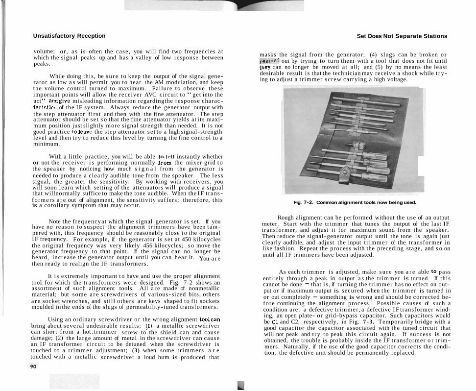
Unsatisfactory Reception Set Does Not Separate Stations
volume; or , a s i s often the case, you will find two frequencies at which the signal peaks up and has a valley of low response between peaks.
While doing this, be su re to keep the output of the signal gene- rator a s low a s will permit you to hear the AM modulation, and keep the volume control turned to maximum. Failure to observe these important points will allow the receiver AVC circuit to "get into the act" andgive misleading information regardingthe response charac- toristics of the IF system. Always reduce the generator output with the step attenuator f i r s t and then with the fine attenuator. The step attenuator should be se t s o that the fine attenuator yields at i t s maxi- mum position just slightly more signal strength than needed. It i s not good practice toleave the step attenuator se t to a high signal-strength level and then t ry t o reduce this level by turning the fine control to a minimum.
With a little practice, you will be able to.tell instantly whether o r not the receiver i s performing normally from the mixer grid t o the speaker by noticing how much s i g n a l from the generator i s needed to produce a clearly audible tone from the speaker. The less signal, the greater the sensitivity. By working with receivers, you will soon learn which setting of the attenuators will produce a signal that willnormally suffice to make the tone audible. When the I F trans- formers a r e out of alignment, the sensitivity suffers; therefore, this is a corollary symptom that may occur.
Note the frequency at which the signal generator i s set. If you have no reason to suspect the alignment t r immers have been tam- pered with, this frequency should be reasonably close t o the original I F frequency. For example, if the generator is se t at 450 kilocycles the original frequency was very likely 456 kilocycles; so move the generator frequency to that point. If the signal can no longer be heard, increase the generator output until you can hear it. You a r e then ready to realign the IF transformers.
It i s extremely important t o have and use the proper alignment tool for which the transformers were designed. Fig. 7-2 shows an assortment of such alignment tools. All a r e made of nonmetallic material; but some a r e screwdrivers of various-sized bits, others a r e socket wrenches, and st i l l others a r e keys shaped to fit sockets moulded in the ends of the slugs of permeability-tuned transformers.
Using an ordinary screwdriver o r the wrong alignment toolcan bring about several undesirable results: (1) a metallic screwdriver can short from a hot .trimmer screw to the shield can and cause damage; (2) the large amount of metal in the screwdriver can cause an IF transformer circuit to be detuned when the screwdriver i s touched to a t r immer adjustment; (3) when some t r immers a r e touched with a metallic screwdriver a loud hum is produced that
masks the signal from the generator; (4) slugs can be broken o r reamed out by trying to turn them with a tool that does not fit until they can no longer be moved at all; and (5) by no means the least desirable result is that the technician may receive a shock while t ry- ing to adjust a t r immer screw carrying a high voltage.
Fig. 7-2. Common alignment tools now being used.
Rough alignment can be performed without the use of an output meter. Start with the tr immer that tunes the output of the last IF transformer, and adjust it for maximum sound from the speaker. Then reduce the signal-generator output until the tone i s again just clearly audible, and adjust the input t r immer of the transformer in like fashion. Repeat the process with the preceding stage, and s o on until all I F t r immers have been adjusted.
As each tr immer i s adjusted, make su re you a r e able to pass entirely through a peak in output a s the tr immer is turned. If this cannot be done - that i s , if turning the t r immer has no effect on out- put or if maximum output is secured when the t r immer is turned in or out completely - something is wrong and should be corrected be- fore continuing the alignment process. Possible causes of such a condition are: a defective t r immer , a defective I F transformer wind- ing, an open plate- o r grid-bypass capacitor. Such capacitors would be C1 and C2, respectively, in Fig. 7-3. Temporarily bridge with a good capacitor the capacitor associated with the tuned circuit that will not peak and t ry to peak this circuit again. If success is not obtained, the trouble is probably inside the I F transformer o r t r im- mers. Naturally, if the use of the good capacitor corrects the condi- tion, the defective unit should be permanently replaced.
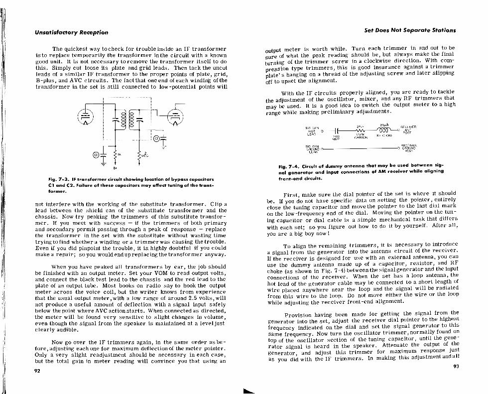
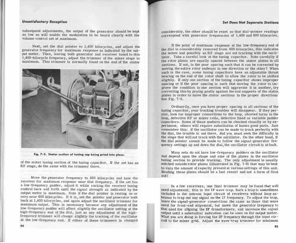
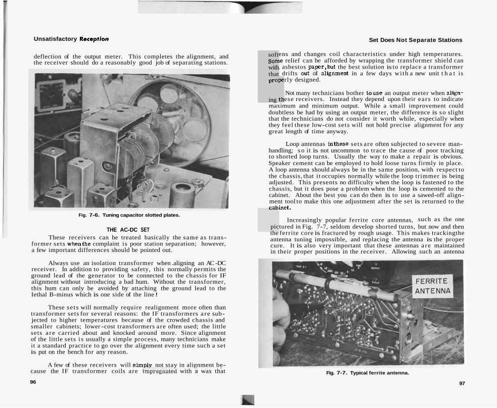
Unsatisfactory deception Set Does Not Separate Stations
deflection of the output meter. This completes the alignment, and the receiver should do a reasonably good job of separating stations.
Fig. 7-6. Tuning capacitor slotted plates.
THE AC-DC SET These receivers can be treated basically the same as trans-
former sets whenthe complaint is poor station separation; however, a few important differences should be pointed out.
Always use an isolation transformer when .aligning an AC -DC receiver. In addition to providing safety, this normally permits the ground lead of the generator to be connected to the chassis for IF alignment without introducing a bad hum. Without the transformer, this hum can only be avoided by attaching the ground lead to the Iethal B-minus which is one side of the line !
These se ts will normally require realignment more often than transformer sets for several reasons: the IF transformers a re sub- jected to higher temperatures because of the crowded chassis and smaller cabinets; lower -cost transformers are often used; the little sets a re carried about and knocked around more. Since alignment of the little sets i s usually a simple process, many technicians make it a standard practice to go over the alignment every time such a set is put on the bench for any reason.
A few of these receivers will simplv not stav in alignment be- - - .
cause the IF transformer coils are im"pregnatei with \ wax that
96
soft som with that
ens and changes coil characteristics under high temperatures. le relief can be afforded by wrapping the transformer shield can L asbestos Daper.but the best solution is to replace a transformer drifts out of aiignment in a few days wi th a new unit t h a t is rly designed. prope
ing th Not many technicians bother touse an output meter when align- ese receivers. Instead they depend upon their ears to indicate
maximum and minimum output. While a small improvement could doubtless be had by using an output meter, the difference is so slight that the technicians do not consider it worth while, especially when they feel these low-cost sets will not hold precise alignment for any great length of time anyway.
Loop antennas inthese sets are often subjected to severe man- handling; s o it is not uncommon to trace the cause of poor tracking to shorted loop turns. Usually the way to make a repair is obvious. Speaker cement can be employed to hold loose turns firmly in place. A loop antenna should always be in the same position, with respect to the chassis, that i t occupies normally while the loop trimmer is being adjusted. This presents no difficulty when the loop is fastened to the chassis, but it does pose a problem when the loop is cemented to the cabinet. About the best you can do then is to use a sawed-off align- ment tool to make this one adjustment after the set is returned to the --%net.
Increasingly popular ferrite core antennas, such as the one pictured in Fig. 7-7, seldom develop shorted turns, but now and then the ferrite core is fractured by rough usage. This makes trackingthe antenna tuning impossible, and replacing the antenna is the proper cure. It is also very important that these antennas a re maintained in their proper positions in the receiver. Allowing such an antenna
Fig. 7-7. Typical ferrite antenna.
97


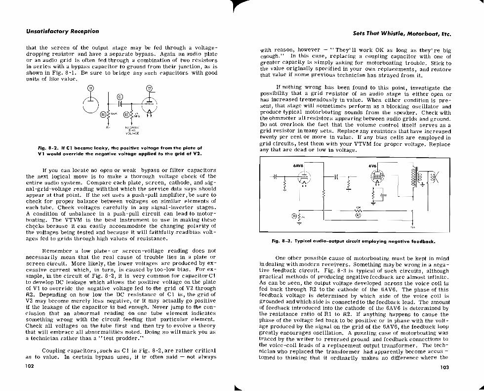
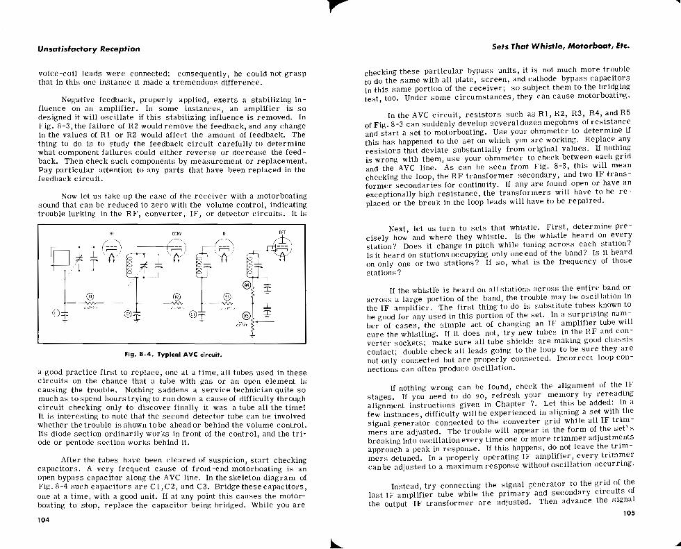

I / Unsatisfactory Reception 1 1
Sets That Whistle, Motorboat, Etc.
generator to the grid of the preceding tube - it may be another IF amplifier or it may be a converter - adjust the tr immers of the transformer primary which appears in the plate circuit of this tube. Keep on advancing the signal-generator connection, one stage at a time, until all trimmers have been adjusted. Sometimes an IF amp- lifier can be aligned in this manner s o that it will perform perfectly without oscillation whenthe same thing cannot be done with the signal generator left connected to the converter grid.
If the IF amplifier cannot be properly aligned without oscillation 1' by any method, then the next thing to look for is an open bypass ca- I 1 1 pacitor. Start by bridging the output filter capacitor. Then bridge all I Ill screen, plate return, cathode, and AVC bypass capacitors connected
I with RF, converter, or IF amplifier tubes. Look carefully to make sure grid and plate leads coming out of IF transformers do not run close to each other. These leads should always be kept as far apart as possible. Make sure IF transformer shields are anchored firmly to the chassis.
Sometimes it helps to know which tube or tubes a re involved in the oscillation. This can usually be determined by touching the grid connection of each tube with a finger tip or with the bit of a fair-sized screwdriver. If the tube is not involved in the oscillation loop, touch- ing the grid will have no effect; on the other hand, if it i s involved, the oscillation will stop while the grid lead is being contacted. While the information thus obtained can be helpful, do not let it mislead you into confining your search for trouble to too small anarea of the c i r- cuit. Quit6 often oscillation is caused by the failure of a part that seems to be quite remote from the tube oscillating. The fact that a change in value of the filter circuit can produce oscillation in an IF amplifier tube is a good example.
If nothing else can be found wrong, it is easily possible that the trouble may lie in an IF transformer. Sometimes heat loosens the windings on their mountings and allows one coil to slide closer'to the other. This upsets the critical coupling that should exist between the primary and secondary windings and will often result in an amplifier that cannot be aligned properly. Try tacking in a new transformer as shown in Fig. 8-5 and described in Chapter 7. Usually inter-stage o r input transformers a re more likely to develop defects that result in oscillation than a re output IF transformers; so, substitute for them first. A transformer that must be widely detuned to stop oscillation is the best place to start your substitution. If substituting a new IF transformer for one in the set stops the oscillation and permits all tr immers to be adjusted on the nose, the new transformer should be permanently installed.
Another common type of whistle is one heard u l l l ~ "11 d station with a frequency twice or three times that of the IF frequency. For example, if the IF frequency is 455 kc, this whistle willonly be heard
on a station at 910 kc or one in the vicinity of 1365 kilocycles. This whistle is produced by the second or third harmonic of the IF fre- quency getting back into the input of the receiver and heterodyning with a transmitted signal being received. In the example given, trouble would be much more likely at 910 kilocycles than at 1365 kilocycles for two reasons: (1) the second harmonic would normally be stronger than the third; (2) since stations are assigned every ten kilocycles, there would be no station at 1365 kilocycles against which
Fig. 8-5. An I F transformer tacked into the circuit.
signal the third harmonic could beat. Of course, if the IF alignment were not precise - a condition quite common - the third harmonic could easily fall on 1360 or 1370 kilocycles.
Look at the skeleton diagram of Fig. 8-6, which shows the detector and audio amplifier section of a typical receiver. Capacitors
and C2 are intended to filter out any IF component or harmonics >m the AVC and audio circuits. If these mica capacitors open up, e job is not accomplished, and then harmonics of the I F frequency n easilv be radiated to the nearby loop antenna.
With the set whistling on the station, try bridging both of these 111s with new capacitors of proper value and see if the sound stops. it does, replace the capacitor shown to be open. While you are at
it, try bridging C3, the plate bypass of the output stage, because the writer has seen cases where the opening of this capacitor will pro- duce the symptom being discussed. More often, though, the opening
107
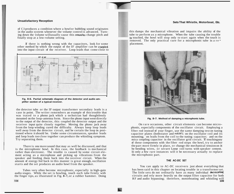
Unsatisfactory Reception
of C3 produces a condition where a howl or bubbling sound originates in the audio system whenever the volume control is advanced. Turn- ing down the volume willusually cause this soundto change pitch and finally stop at a low-volume setting.
If there is nothing wrong with the capacitors, look for some other method by which the output of the IF amplifier can be c o ~ p l e d into the input circuit of the receiver. Loop leads that come close to
I DET-Af AMP
1 1 Fig. 8-6. Partial schematic diagram of the detector and audio am- plifier section of a typical receiver.
the detector tube or the IF output transformer secondary leads i s a case in point. The writer remembers an example of this trouble that was traced to a phono jack which a technician had thoughtlessly mounted on the loop-antenna form. Since the phono input went directly to the output of the detector, this coupled the detector output and the receiver input quite closely together. Moving the phono jack away from the loop winding cured the difficulty. Always keep loop leads well away from the detector circuit, and be certain the loop is posi- tioned where it should be. Under some circumstances, speaker leads and loop leads too close together can produce the whistling symptom. Try separating them.
There is one more sound that may as well be discussed, and that is the microphonic howl. In this case, the feedback is mechanical rather than electronic. The trouble i s caused by some circuit ele- ment acting as a microphone and picking up vibrations from the speaker and feeding them back into the receiver circuit. When the amount of energy fed back in this manner i s great enough, oscillation s tar ts and the set produces an audio howl from the speaker.
Tubes very often become microphonic, especially in high-gain audio stages. While the set is howling, touch each tube firmly with the finger tips, a s illustrated in Fig. 8-7, or a rubber hammer. Doing
Sets That Whistle, Motorboat, Etc.
this damps the mechanical vibration and impairs the ability of the tube to perform a s a microphone. When the tube causing the trouble is touched, the howl will stop only to start again when the touch is removed. The only practical cure for a microphonic tube is a r e - placement.
Fig. 8-7. Method of damping a microphonic tube.
On r a r e occasions, other circuit elements can become micro- phonic, especially components of the oscillator circuit. Employing a fiber rod instead of your finger, use the same damping test on tuning capacitor plates (both stator and rotm); on the oscillator coil and its mounting; on leads from the coil to the tuning capacitor; and on the mica coupling capacitor in the oscillator grid circuit. If touchingany of these components with the fiber rod stops the howl, t ry to anchor the part more firmly in place, o r change the mechanical tension on it by bending wires, o r secure Loose coil turns with speaker cement. In only a few rare instances will it be necessary actually to replace the microphonic part.
THE AC-DC SET
You can apply to AC-DC receivers just about everything that has been said in this chapter on locating trouble in a transformer set. The little sets do not ordinarily have a s many individual decoupling circuits and rely more heavily on the output filter capacitor for both R F and audio bypassing; therefore, motorboating and whistling will
109

Unsatisfactory Reception
more often be t raced t o a fai lure of this component in AC-DC sets . Defective tubes and open bypass capaci tors occur about a s often in one type of s e t a s in any other.
While checking capaci tors , do not overlook the one ordinarily found between B-minus and the chassis . If this opens up, it can pro- duce motorboating and whistling. Also be on the a le r t for a special type of bypass capacitor often found in the I F circui ts of modern sets . This capacitor is designed to be self- resonant a t the I F frequency and does a much bet ter job of bypassing this one frequency than does a n ordinary tubular capacitor of the s a m e value. A special capacitor of this nature will usually be identified either by special marking on
Fig. 8-8. Self-resonant capacitor used in modern sets.
the unit s imi la r t o that shown in Fig. 8-8, o r by a description in the se rv ice data. Make s u r e some other technician has not replaced such a capacitor with an ordinary type. If he has, this may make it i m- possible to keep the I F amplifier f r o m oscillating. Always follow serv ice data recommendations exactly in replacing such capacitors.
THE THREE-WAY PORTABLE RECEIVER
Again the instructions given for t rans former type s e t s should be carefully reviewed and followed in dealing with motorboating and whistling in these receivers . They will be found t o be much more susceptible t o microphonic-tube trouble than a r e the other twotypes of receivers . In fact, i t may be necessary t o t r y twoor threenew tubes in some s e t s before one will be found that i s f r e e of this trouble. Do not re tu rn the other new tubes a s defective, however, until you have t r i e d them in another receiver . In a second s e t they may give no trouble whatever.
Open loop leads will be found quite often in these rece ivers and may lead t o motorboating o r whistling. Always check this possibility carefully. Broken connections and shor t c i rcui ts a r e quite common in these rece ivers a s a resul t of the rough handling they often receive. Such defects can lead t o oscillation of various types. Quite often, a s has been mentioned before, miniature-tube-socket connections fail to
Sets That Whistle, Motorboat, Etc.
make good connection t o tube pins. If such a poor connection occurs on a shield-grounding pin, oscillation may well resul t . Moving tubes gently in their socket will ordinarily spotlight the trouble by causing the oscillation t o s t a r t and s top a s the tube in the offending socke t is shifted. If a bad socket is found, it can ordinari ly be repaired by restor ing the pin-gripping jaws totheir proper position with a sharp- pointed tool.
In a few instances, one of these s e t s will oscillate w h e n operating on bat ter ies if the B-battery is old o r partially exhausted. Replacing the battery with a f r e s h unit will c l e a r up the difficulty.
QUESTIONS
1. Motorboating is usually caused by a defect in what c ircui ts? 2. What conditions a r e necessary t o produce oscillation? 3. How can a weakening output f i l t e r capacitor produce motorboating? 4. A r e capacity values of audio coupling capacitors cr i t ical? Explain. 5. What can happen in a negative feedback circuit t o produce oscil-
lation? 6. Does the second detector tube work ahead of o r behind thevolume
control? 7. R h e n an I F amplifier oscillates, what is the f i r s t thing t o do? 8. Explain how a defective I F t rans former can cause oscillation. 9. What causes a whistle on a station whose frequency is twice o r
th ree t i m e s that of the I F frequency? 10. What precautions a r e necessary inreplacing aself- resonance c a-
paci tor? 6
11. When a three-way portable oscillates on bat ter ies but not on AC, what is a possible cause?
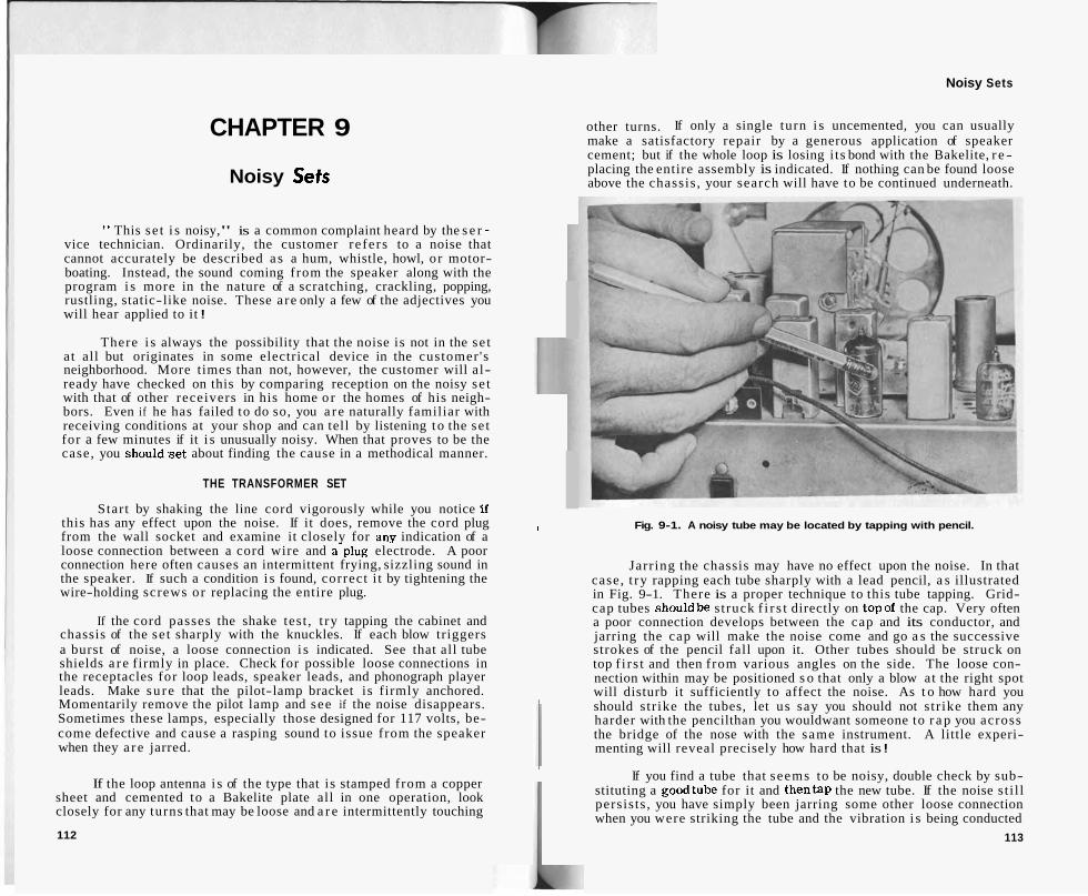
Noisy Sets
CHAPTER 9
Noisy Sets
other turns. If only a single turn i s uncemented, you can usually make a satisfactory repair by a generous application of speaker cement; but if the whole loop is losing i ts bond with the Bakelite, r e - placing the entire assembly is indicated. If nothing can be found loose above the chassis , your search will have to be continued underneath.
" This se t i s noisy," is a common complaint heard by the s e r - vice technician. Ordinarily, the customer refers to a noise that cannot accurately be described a s a hum, whistle, howl, or motor- boating. Instead, the sound coming from the speaker along with the program i s more in the nature of a scratching, crackling, popping, rustling, static-like noise. These are only a few of the adjectives you will hear applied to it !
There i s always the possibility that the noise is not in the se t at all but originates in some electrical device in the customer 's neighborhood. More times than not, however, the customer will al- ready have checked on this by comparing reception on the noisy se t with that of other receivers in his home o r the homes of his neigh- bors. Even if he has failed to do so, you a re naturally familiar with receiving conditions at your shop and can tell by listening to the se t for a few minutes if it i s unusually noisy. When that proves to be the case, you shouldset about finding the cause in a methodical manner.
THE TRANSFORMER SET
Start by shaking the line cord vigorously while you notice If this has any effect upon the noise. If it does, remove the cord plug from the wall socket and examine it closely for any indication of a loose connection between a cord wire and a-plug electrode. A poor connection here often causes an intermittent frying, sizzling sound in the speaker. If such a condition i s found, correct i t by tightening the wire-holding screws or replacing the entire plug.
If the cord passes the shake test , t ry tapping the cabinet and chassis of the se t sharply with the knuckles. If each blow triggers a burst of noise, a loose connection i s indicated. See that all tube shields a r e firmly in place. Check for possible loose connections in the receptacles for loop leads, speaker leads, and phonograph player leads. Make su re that the pilot-lamp bracket is firmly anchored. Momentarily remove the pilot lamp and see if the noise disappears. Sometimes these lamps, especially those designed for 117 volts, be- come defective and cause a rasping sound to issue from the speaker when they a re jarred.
If the loop antenna i s of the type that is stamped from a copper sheet and cemented to a Bakelite plate all in one operation, look closely for any turns that may be loose and a r e intermittently touching
112
Fig. 9-1. A noisy tube may be located by tapping with pencil. I
Jarring the chassis may have no effect upon the noise. In that case, t ry rapping each tube sharply with a lead pencil, a s illustrated in Fig. 9-1. There is a proper technique to this tube tapping. Grid- cap tubes shouldbe struck f i r s t directly on topof the cap. Very often a poor connection develops between the cap and its conductor, and jarring the cap will make the noise come and go a s the successive strokes of the pencil fall upon it. Other tubes should be struck on top f i r s t and then from various angles on the side. The loose con- nection within may be positioned s o that only a blow at the right spot will disturb it sufficiently to affect the noise. As t o how hard you should str ike the tubes, let us say you should not s tr ike them any harder with the pencilthan you wouldwant someone to r a p you across the bridge of the nose with the same instrument. A little experi- menting will reveal precisely how hard that is !
If you find a tube that seems to be noisy, double check by sub- stituting a goodtube for it and thentap the new tube. If the noise st i l l persists , you have simply been jarring some other loose connection when you were striking the tube and the vibration i s being conducted
113

Unsatisfactory Reception Noisy Sets
through the chassis. Some noisy tubes have to reach a certain tem- perature beforethe noise shows up. Once past this temperature,they will not make a noise until they have cooled down again. Quizzing the customer about the peculiarities of the noise may save you a lot of trouble in looking for it.
Fig. 9-2. Checking for an off-center voice coil.
In a few instances, the noise will only show up when a signal is being received; yet no thumping on the chassis or tubes will produce it while no station is tuned in. That should make you suspicious ofthe speaker. Sometimes tiny metal filings will get into the gap between the voice coil and the speaker frame and cause an intermittent short as the voice coil moves back and forth. The same result is had when the voice coil is off center and the winding itself rubs on the frame. To test for this condition, slowly move the cone back and forth with your fingers, as shown in Fig. 9-2, while the receiver is turned on and notice if the scratching sound is heard at any one ppsition of the cone. If it is, you have tracked down the varmint! To dispatch i t , t ry first to recenter the cone with speaker shims in the conventional manner. If there are metal particles in the gap, they can often be blown out with compressed air or removed by the delicate manipula- tion of a thin, flexible-metal, speaker shim.
When you have checked all these things but have not located the source of the noise, try substituting new tubes one at a time in all the sockets of the set. If that does not help, you may as well pull the chassis and s tar t looking beneath it. If jarring affected the noise,
tap the various circuit components lightly with an insulated alignment tool. Pay particular attention to socket connections, capacitors sus- pended by their leads, resistors, line-switch terminals, and band- changing switch contacts. When the source of the trouble is found - and a simple loose connection cannot elude big sm'art you for very long - the solution will be obvious.
When the noise is not affected by jarring, waste no time; break out your signal tracer at once. Start with the plate of the output stage andadvance a stageat a time towardthe front of the set. As you con- tact each plate connection with the probe, listen to see if the noise is still present. When you find a plate at which it cannot be heard, the noise obviously originates in the stage following. Each stage in a receiver has its own most likely sources of noise; so let' s take them up one at a time.
When you can only hear the noise at the output-tube plate, cut loose any capacitors that may appear between that plate and ground or cathode. If that does not stop the noise, the trouble is probably a partially open primary in the output transformer. Such a defect r e - sults in noise at any setting of the volume control, and it is usually worse when the set is first turned on. The crackling, frying disturb- ance is often accompanied by a squeaking sound. You can be sure by turning off the set, removing the output tube, clipping a 10-watt, 10,000-ohm resistor between the plate connection of the output-tube socket and ground, and turning the se t on again. This will allow about the proper amount of current to flow through the primary of the trans - former. If you still hear the noise, you may be almost certain the primary is at fault; however, tacking a new transformer into the circuit in its place will settle the matter beyond all doubt.
If nonoise canbe heard whenthe output tube is out of its socket, the noise must be coming from some other circuits of the output stage. Check all resistors and capacitors connected with that stage by cut- ting the units out of the circuit one at time and substituting known good parts for them.
Next suppose the noise is found originating at the plate of the audio amplifier stage. The conventional audio stage has a mica ca- pacitor going from the plate connection to ground. Many times this capacitor develops a partially shorted condition that will result in a very noisy set. Cut one end of the capacitor loose and see if the noise stops. If i t does, replace the capacitor. If the noise continues, perhaps the plate resistor is noisy. Tack another in i ts place and see. When the audio stage is a pentode type, do the same with the screen- dropping resistor and its bypass capacitor. In a few cases, you will find a coupling audio transformer betweenthe audio amplifier andthe output stage. The primary of this transformer can give the same trouble a s the primary of the output transformer, and i t can IX checked in the same way. However, the resistor used to load down the primary while the audio amplifier tube is out of i ts socket should be approximately 30,000 ohms.
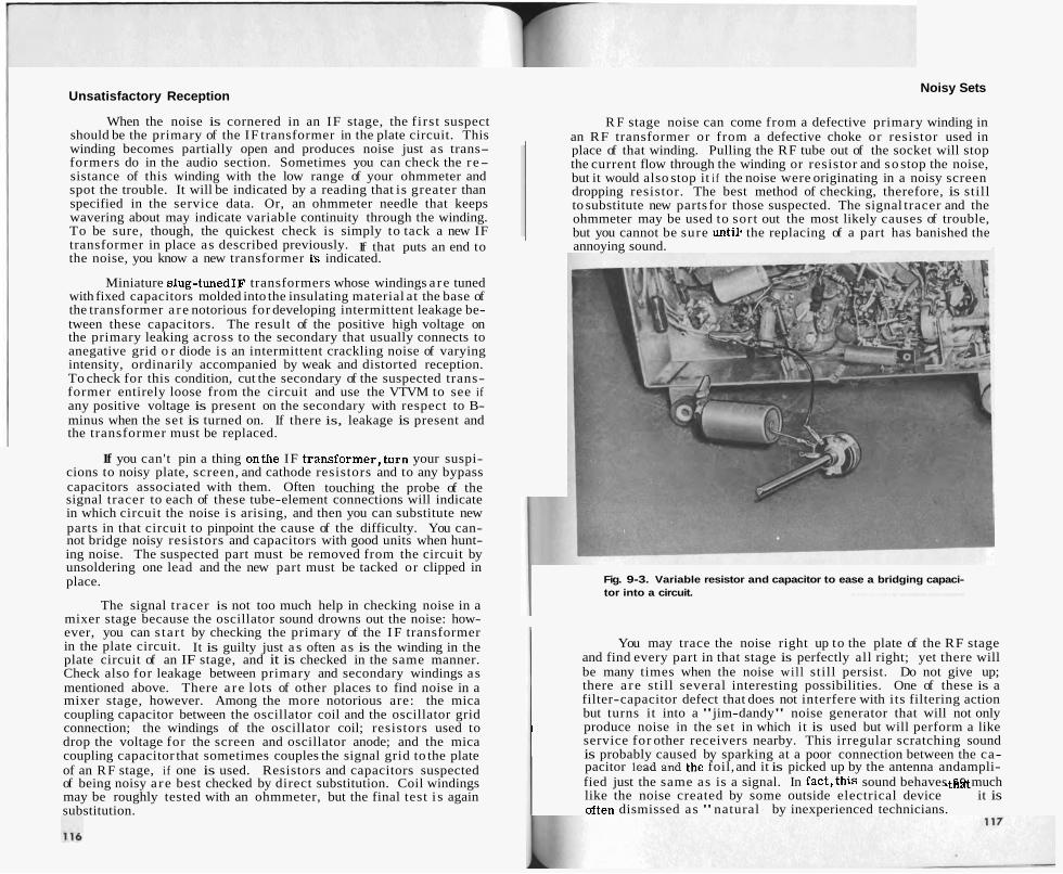
Unsatisfactory Reception
When the noise is cornered in an IF stage, the first suspect should be the primary of the IF transformer in the plate circuit. This winding becomes partially open and produces noise just as trans- formers do in the audio section. Sometimes you can check the re- sistance of this winding with the low range of your ohmmeter and spot the trouble. It will be indicated by a reading that is greater than specified in the service data. Or, an ohmmeter needle that keeps wavering about may indicate variable continuity through the winding. To be sure, though, the quickest check is simply to tack a new IF transformer in place as described previously. If that puts an end to the noise, you know a new transformer is indicated.
Miniature slug-tunedIF transformers whose windings a re tuned with fixed capacitors molded into the insulating material at the base of the transformer a re notorious for developing intermittent leakage be- tween these capacitors. The result of the positive high voltage on the primary leaking across to the secondary that usually connects to anegative grid o r diode is an intermittent crackling noise of varying intensity, ordinarily accompanied by weak and distorted reception. To check for this condition, cut the secondary of the suspected trans- former entirely loose from the circuit and use the VTVM to see if any positive voltage is present on the secondary with respect to B- minus when the set is turned on. If there is, leakage is present and the transformer must be replaced.
If you can't pin a thing onthe IF transformer,turn your suspi- cions to noisy plate, screen, and cathode resistors and to any bypass capacitors associated with them. Often touching the probe of the signal tracer to each of these tube-element connections will indicate in which circuit the noise i s arising, and then you can substitute new parts in that circuit to pinpoint the cause of the difficulty. You can- not bridge noisy resistors and capacitors with good units when hunt- ing noise. The suspected part must be removed from the circuit by unsoldering one lead and the new part must be tacked or clipped in place.
The signal tracer is not too much help in checking noise in a mixer stage because the oscillator sound drowns out the noise: how- ever, you can s tar t by checking the primary of the I F transformer in the plate circuit. It is guilty just a s often as is the winding in the plate circuit of an IF stage, and it is checked in the same manner. Check also for leakage between primary and secondary windings as mentioned above. There a re lots of other places to find noise in a mixer stage, however. Among the more notorious are: the mica coupling capacitor between the oscillator coil and the oscillator grid connection; the windings of the oscillator coil; resistors used to drop the voltage for the screen and oscillator anode; and the mica coupling capacitor that sometimes couples the signal grid to the plate of an R F stage, i f one is used. Resistors and capacitors suspected of being noisy a re best checked by direct substitution. Coil windings may be roughly tested with an ohmmeter, but the final test i s again substitution.
Noisy Sets
R F stage noise can come from a defective primary winding in an RF transformer or from a defective choke or resistor used in place of that winding. Pulling the RF tube out of the socket will stop the current flow through the winding or resistor and so stop the noise, but it would also stop it i f the noise were originating in a noisy screen dropping resistor. The best method of checking, therefore, is still to substitute new parts for those suspected. The signal tracer and the ohmmeter may be used to sort out the most likely causes of trouble, but you cannot be sure until. the replacing of a part has banished the annoying sound.
Fig. 9-3. Variable resistor and capacitor to ease a bridging capaci- tor into a circuit.
You may trace the noise right up to the plate of the RF stage and find every part in that stage is perfectly all right; yet there will be many times when the noise will still persist. Do not give up; there a re still several interesting possibilities. One of these is a filter-capacitor defect that does not interfere with its filtering action but turns it into a "jim-dandy" noise generator that will not only produce noise in the set in which it is used but will perform a like I service for other receivers nearby. This irregular scratching sound is probably caused by sparking at a poor connection between the ca- pacitor lead and the foil, and it is picked up by the antenna andampli- fied just the same as is a signal. In fact,this sound behaves SO much like the noise created by some outside electrical device sthat it is often dismissed as "natural f
f by inexperienced technicians.
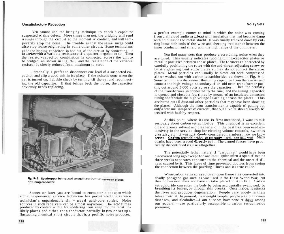
Unsatisfactory Reception
You cannot use the bridging technique to check a capacitor suspected of this defect. More times than not, the bridging will send a surge through the circuit at the moment of contact, and will tem- porarily stop the noise. The trouble is that the same surge could also stop noise originating in some other circuit. Some technicians ease the briding capacitor in and out of the circuit by connecting it inseries with a variable resistance of a quarter megohm or so. Then the resistor-capacitor combination is connected across the unit to be bridged, as shown in Fig. 9-3, and the resistance of the variable resistor is slowly reduced from maximum to zero.
Personally, I prefer to disconnect one lead of a suspected ca- pacitor and clip a good unit in its place. If the noise is gone when the set is turned on, I double check by turning off the set and reconnect- ing the old capacitor. If that brings back the noise, the capacitor obviously needs replacing.
Fig. 9-4. Eyedropper being used to squirt carbon-tet b of tuning capacitor.
ates
Sooner or later you are bound to encounter a s e t upon which some inexperienced service technician has perpetrated the service technician' s unpardonable sin - u s e d acid-core solder. Noise sources in such receivers can be almost anywhere. The acid fumes produced by contact with a hot soldering iron seep into the most un- likely places and either eat a conductor partially in two or set up a fluctuating chemical short circuit that is a prolific noise producer.
Noisy Sets
A perfect example comes to mind in which the noise was coming from a shielded audio gridlead with insulation that had become damp with acid inside the metal shield. It was finally tracked down by cut- ting loose both ends of the wire and checking resistance between the inner conductor and shield with the high range of the ohmmeter.
You find many sets that produce a scratching noise when they are tuned. This usually indicates rubbing tuning-capacitor plates o r metallic particles between those plates. The former a r e corrected by carefully positioning the rotor with the end-thrust adjusting screw or by straightening bent rotor plates so they do not contact the stator plates. Metal particles can usually be blown out with compressed air o r washed out with carbon tetrachloride, as shown in Fig. 9-4. Some technicians disconnect the tuning capacitor from the circuit and connect the high-voltage secondary of an old neon transformer put- ting out around 5,000 volts across the capacitor. Then the primary of the transformer is connected to the line, and the tuning capacitor is opened and closed a few times by means of an insulated extension tuning shaft while the high voltage i s arcing across the plates. This arc burns out all dust and other particles that may have been shorting the plates. Although the neon transformer is capable of putting out only a few milliamperes of current, that 5,000 volts should always be treated with healthy respect.
At this point, where i ts use is first mentioned, I want to talk seriously about carbon tetrachloride. This chemical is an excellent oil and grease solvent and cleaner and in the past has been used ex- tensively in the service shop for cleaning volume controls, switches crvstals. etc. It was mistakenlv considered harmless; now we know L i t e r . carbon tetrachloride, carelessly used, can dl you! Many deaths have been traced directlv to it. The armed forces have prac- tically discontinued its use altogether.
The potentially lethal nature of "carbon tet" would have been discovered long ago except for one fact: quite often a span of two o r three weeks separates exposure to the chemical and the onset of ill- ness caused by it. This lapse of time prevented doctors from seeing the connection between the puzzling illness and its true cause.
When carbon tet is sprayed on an open flame it is converted into deadly phosgene gas such as was used in the Firs t World War; but this conversion does not have to take place for i t to kill. Carbon tetrachloride can enter the body by being accidentally swallowed, by breathing its fumes, or through skin breaks. Once inside, it attacks the liver and produces degeneration. People vary widely in their toleranceto it. In general, overweight people, people with pulmonary diseases, and alcoholics--I am sure we have none of these among our readers! --are particularly susceptible to carbon tetrachloride poisoning.

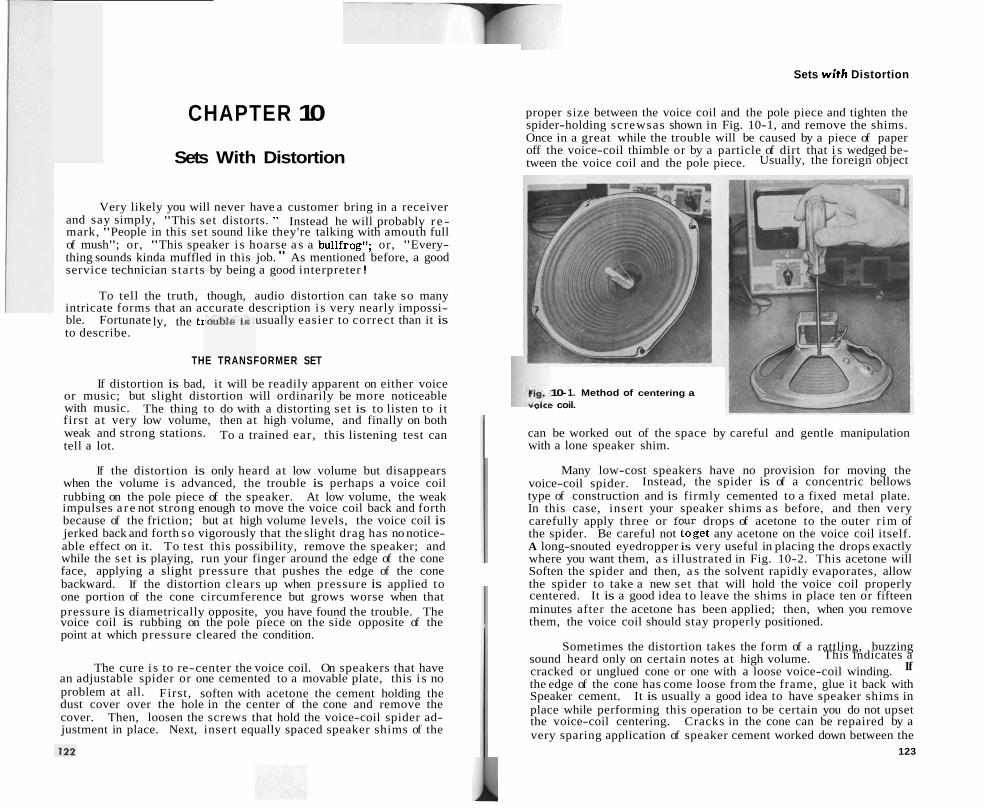
Sets wi th Distortion
CHAPTER 10
Sets With Distortion
Very likely you will never have a customer bring in a receiver and say simply, "This set distorts. " Instead he will probably r e - mark, "People in this set sound like they're talking with amouth full of mush"; or, "This speaker i s hoarse a s a bullfrog'l; or, "Every- thing sounds kinda muffled in this job. " As mentioned before, a good service technician starts by being a good interpreter !
To tell the truth, though, audio distortion can take so many intricate forms that an accurate description i s very nearly impossi- ble. Fortunate usually easier to correct than it is to describe.
ly, the tr
THE TRANSFORMER SET
If distortion is bad, it will be readily apparent on either voice or music; but slight distortion will ordinarily be more noticeable with music. The thing to do with a distorting set is to listen to i t first at very low volume, then at high volume, and finally on both weak and strong stations. To a trained ear, this listening test can tell a lot.
If the distortion is only heard at low volume but disappears when the volume i s advanced, the trouble is perhaps a voice coil rubbing on the pole piece of the speaker. At low volume, the weak impulses a re not strong enough to move the voice coil back and forth because of the friction; but at high volume levels, the voice coil is jerked back and forth so vigorously that the slight drag has no notice- able effect on it. To test this possibility, remove the speaker; and while the set is playing, run your finger around the edge of the cone face, applying a slight pressure that pushes the edge of the cone backward. If the distortion clears up when pressure is applied to one portion of the cone circumference but grows worse when that pressure is diametrically opposite, you have found the trouble. The voice coil is rubbing on the pole piece on the side opposite of the point at which pressure cleared the condition.
The cure i s to re-center the voice coil. On speakers that have an adjustable spider or one cemented to a movable plate, this i s no problem at all. First, soften with acetone the cement holding the dust cover over the hole in the center of the cone and remove the cover. Then, loosen the screws that hold the voice-coil spider ad- justment in place. Next, insert equally spaced speaker shims of the
proper size between the voice coil and the pole piece and tighten the spider-holding screwsas shown in Fig. 10-1, and remove the shims. Once in a great while the trouble will be caused by a piece of paper off the voice-coil thimble or by a particle of dirt that i s wedged be- tween the voice coil and the pole piece. Usually, the foreign object
10- 1. Method of centering a . -.-> coil.
can be worked out of the space by careful and gentle manipulation with a lone speaker shim.
Many low-cost speakers have no provision for moving the voice-coil spider. Instead, the spider is of a concentric bellows type of construction and is firmly cemented to a fixed metal plate. In this case, insert your speaker shims a s before, and then very carefully apply three or four drops of acetone to the outer r im of the spider. Be careful not toget any acetone on the voice coil itself. A long-snouted eyedropper is very useful in placing the drops exactly where you want them, a s illustrated in Fig. 10-2. This acetone will Soften the spider and then, a s the solvent rapidly evaporates, allow the spider to take a new set that will hold the voice coil properly centered. It is a good idea to leave the shims in place ten or fifteen minutes after the acetone has been applied; then, when you remove them, the voice coil should stay properly positioned.
Sometimes the distortion takes the form of a rattling, buzzing sound heard only on certain notes at high volume. This indicates a cracked or unglued cone or one with a loose voice-coil winding. If
the edge of the cone has come loose from the frame, glue it back with Speaker cement. It is usually a good idea to have speaker shims in place while performing this operation to be certain you do not upset the voice-coil centering. Cracks in the cone can be repaired by a very sparing application of speaker cement worked down between the
123
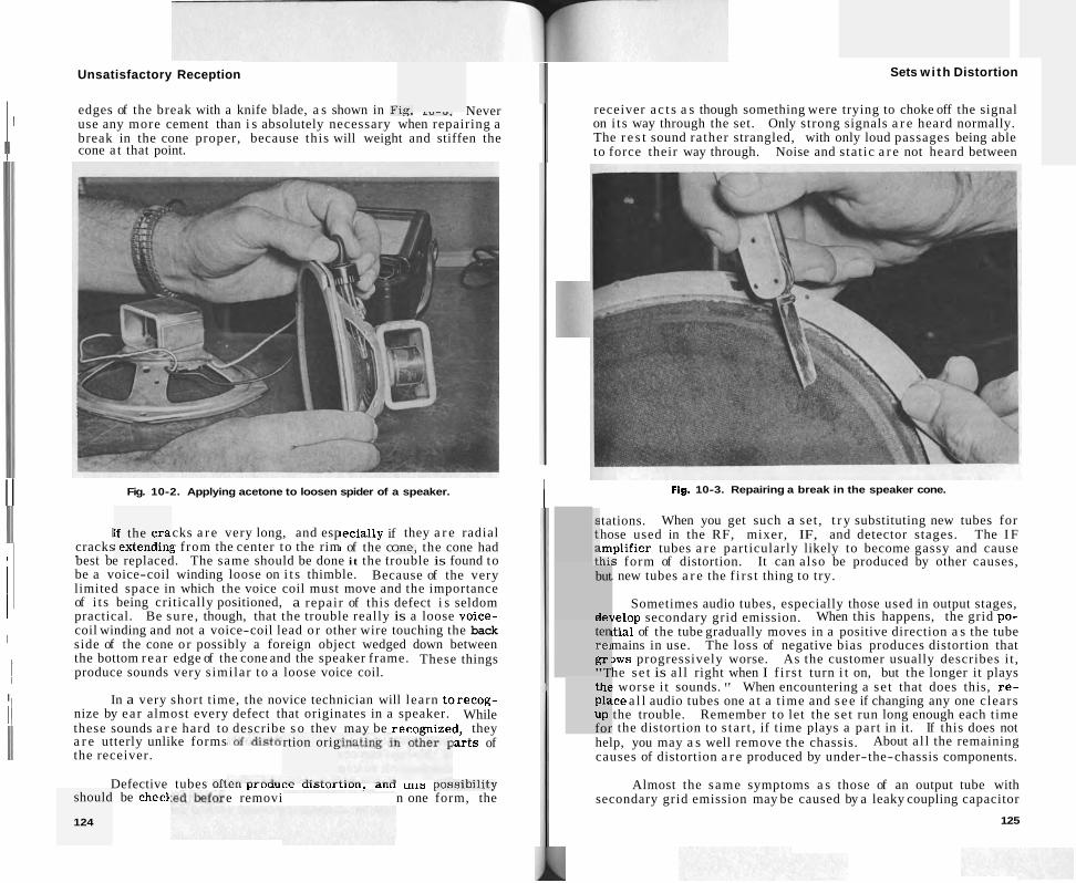
Unsatisfactory Reception
edges of the break with a knife blade, a s shown in FIG. L v - u . Never I I use any more cement than i s absolutely necessary when repairing a break in the cone proper, because this will weight and stiffen the
/ I cone a t that point.
I I Fig. 10-2. Applying acetone to loosen spider of a speaker. 1 I
cracks . . -
[f the c ra ; extendin1
~ecial ly if I of the cc
.
I I In a very short time, the novice technician will learn torecog-
: 1 nize by ear almost every defect that originates in a speaker. While these sounds a r e hard to describe s o thev mav be recomized, they a r e utterly unlike forms larts of the receiver.
cks a r e very long, and esp they a r e radial
rtion orig
i '
Defective tubes oft^^^ p l UUULC UIDLUI LIUII. ~ I I U LIILD p ~ ~ ~ i b i l i t y e removi n one form, the
g from the center to the rim me, the cone had best be replaced. The same should be done i t the trouble is found to be a voice-coil winding loose on i t s thimble. Because of the very limited space in which the voice coil must move and the importance
should
124
I ~ of i t s being critically positioned, a repair of this defect i s seldom practical. Be sure , though, that the trouble really is a loose voice- coil winding and not a voice-coil lead or other wire touching the back
I I side of the cone or possibly a foreign object wedged down between
l 1 the bottom r ea r edge of the cone and the speaker frame. These things produce sounds very similar to a loose voice coil.
1
be check
Sets w i th Distortion
receiver ac t s a s though something were trying to choke off the signal on i t s way through the set. Only strong signals a r e heard normally. The r e s t sound rather strangled, with only loud passages being able to force their way through. Noise and stat ic a r e not heard between
Fig. 10-3. Repairing a break in the speaker cone.
but
del -- ten re1 gr "T thc pla UP for
tations. When you get such a set , t r y substituting new tubes for hose used in the RF, mixer, IF, and detector stages. The I F .mplifier tubes a r e particularly likely to become gassy and cause h i s form of distortion. It can also be produced by other causes,
. new tubes a r e the f i r s t thing to try.
Sometimes audio tubes, especially those used in output stages, irelop secondary grid emission. When this happens, the grid po- ltial of the tube gradually moves in a positive direction a s the tube mains in use. The loss of negative bias produces distortion that ,ws progressively worse. As the customer usually describes i t , he s e t is a l l right when I f i r s t turn i t on, but the longer it plays ! worse i t sounds. " When encountering a se t that does this, r e - rce a l l audio tubes one a t a t ime and s ee if changing any one clears the trouble. Remember to let the se t run long enough each time
a the distortion to s ta r t , if time plays a part in it. If this does not help, you may a s well remove the chassis. About a l l the remaining causes of distortion a r e produced by under-the-chassis components.
Almost the same symptoms a s those of an output tube with secondary grid emission may be caused by a leaky coupling capacitor
125

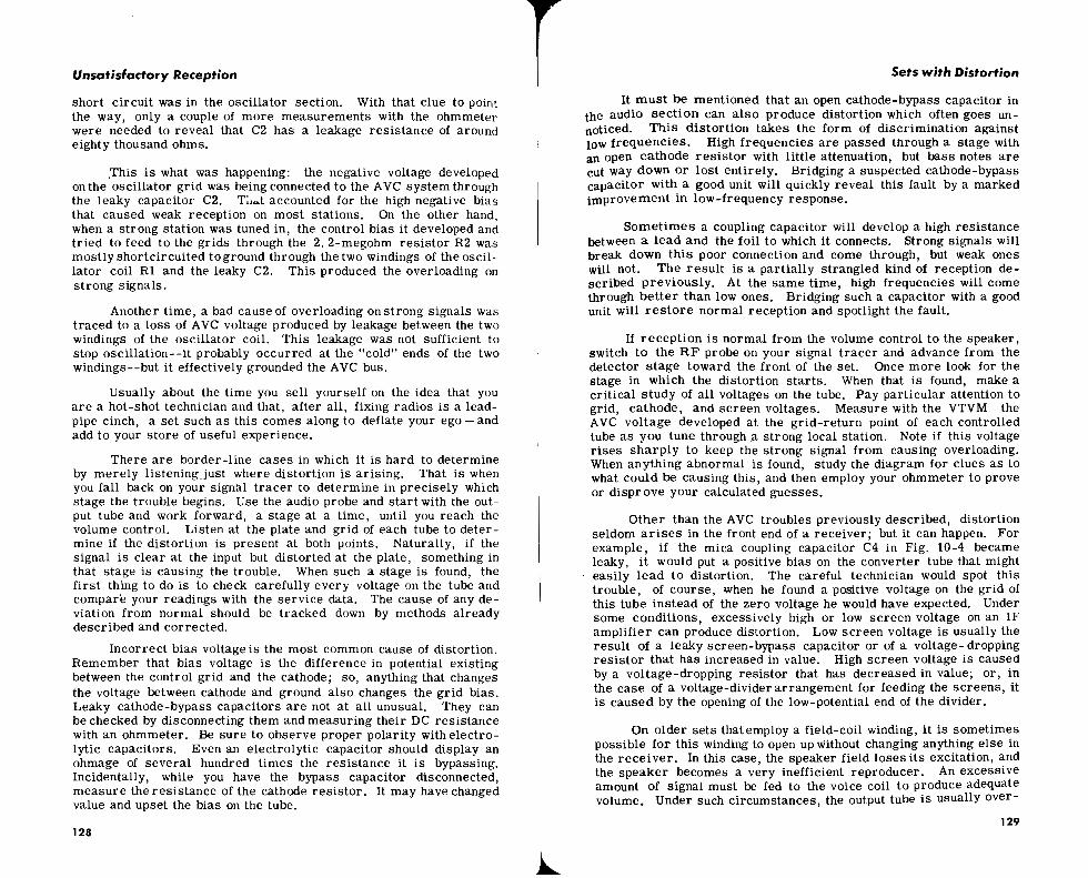
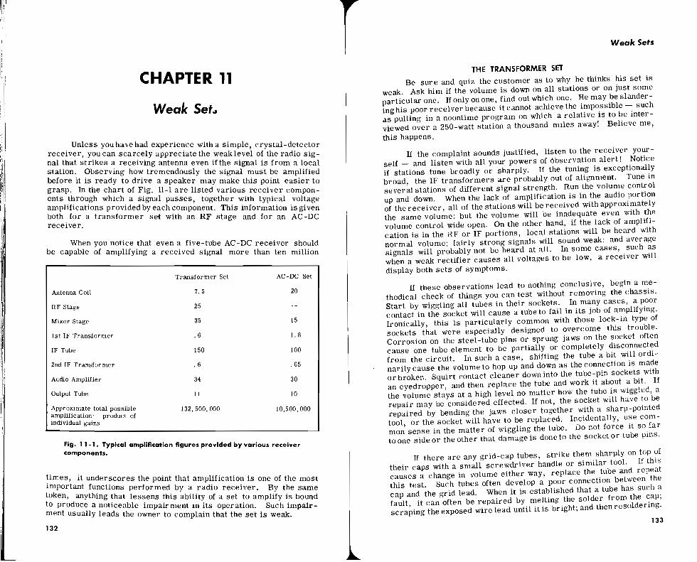
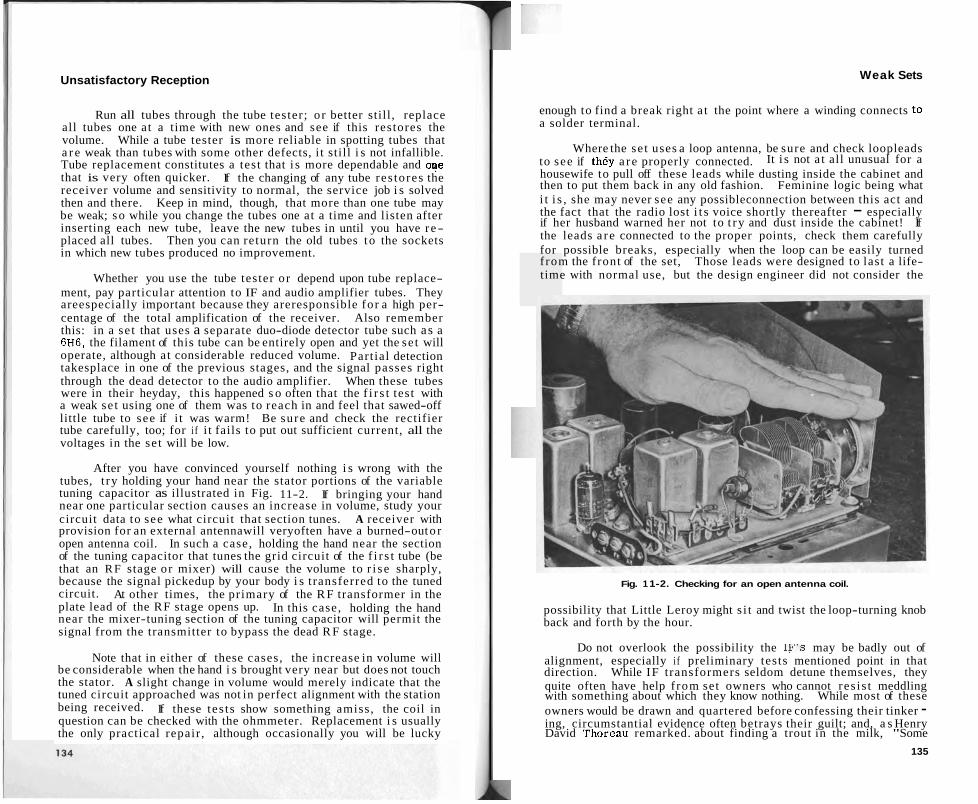
Unsatisfactory Reception
Run all tubes through the tube tester; or better still , replace all tubes one at a time with new ones and see if this restores the volume. While a tube tester is more reliable in spotting tubes that a r e weak than tubes with some other defects, i t still i s not infallible. Tube replacement constitutes a test that i s more dependable and oTe that is very often quicker. If the changing of any tube res tores the receiver volume and sensitivity to normal, the service job i s solved then and there. Keep in mind, though, that more than one tube may be weak; so while you change the tubes one at a time and listen after inserting each new tube, leave the new tubes in until you have r e- placed all tubes. Then you can return the old tubes t o the sockets in which new tubes produced no improvement.
Whether you use the tube tester or depend upon tube replace- ment, pay particular attention to IF and audio amplifier tubes. They areespecially important because they areresponsible for a high per- centage of the total amplification of the receiver. Also remember this: in a se t that uses a separate duo-diode detector tube such as a 6H6, the filament of this tube can be entirely open and yet the se t will operate, although at considerable reduced volume. Part ial detection takesplace in one of the previous stages, and the signal passes right through the dead detector to the audio amplifier. When these tubes were in their heyday, this happened s o often that the f i r s t test with a weak se t using one of them was to reach in and feel that sawed-off little tube to see if i t was warm! Be sure and check the rectifier tube carefully, too; for i f i t fails to put out sufficient current, all the voltages in the se t will be low.
After you have convinced yourself nothing i s wrong with the tubes, t ry holding your hand near the stator portions of the variable tuning capacitor as illustrated in Fig. 11-2. If bringing your hand near one particular section causes an increase in volume, study your circuit data to see what circuit that section tunes. A receiver with provision for an external antennawill veryoften have a burned-out o r open antenna coil. In such a case, holding the hand near the section of the tuning capacitor that tunes the grid circuit of the f i r s t tube (be that an R F stage or mixer) will cause the volume to r i s e sharply, because the signal pickedup by your body i s t ransferred to the tuned circuit. At other times, the primary of the R F transformer in the plate lead of the RF stage opens up. In this case, holding the hand near the mixer-tuning section of the tuning capacitor will permit the signal from the transmitter to bypass the dead R F stage.
Note that in either of these cases, the increase in volume will be considerable when the hand i s brought very near but does not touch the stator. A slight change in volume would merely indicate that the tuned circuit approached was not in perfect alignment with the station being received. If these tes t s show something amiss, the coil in question can be checked with the ohmmeter. Replacement i s usually the only practical repair , although occasionally you will be lucky
Weak Sets
enough to find a break right a t the point where a winding connects to a solder terminal.
Where the se t uses a loop antenna, be sure and check loopleads to see if they a r e properly connected. It i s not a t all unusual for a housewife to pull off these leads while dusting inside the cabinet and then to put them back in any old fashion. Feminine logic being what i t i s , she may never see any possibleconnection between this act and the fact that the radio lost i t s voice shortly thereafter - especially if her husband warned her not to t ry and dust inside the cabinet! If the leads a r e connected to the proper points, check them carefully for possible breaks, especially when the loop can be easily turned f rom the front of the set, Those leads were designed to last a life- time with normal use, but the design engineer did not consider the
Fig. 1 1-2. Checking for an open antenna coil.
possibility that Little Leroy might s i t and twist the loop-turning knob back and forth by the hour.
Do not overlook the possibility the IF'S may be badly out of alignment, especially i f preliminary tests mentioned point in that direction. While IF transformers seldom detune themselves, they quite often have help f rom set owners who cannot res is t meddling with something about which they know nothing. While most of these owners would be drawn and quartered before confessing their tinker - ing, circumstantial evidence often betrays their guilt; and, a s Henry David Thoreau remarked. about finding a trout in the milk, "Some
135
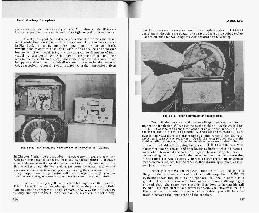
Unsatisfactory Reception
circumstantial evidence is very strong! " Finding al l the IF trans- former adjustment sc rews turned down tight is just such evidence.
Usually a signal generator can be connected a c r o s s the mixer input while the chass i s is st i l l in the cabinet of a console a s shown in Fig. 11-3. Then, by tuning the signal generator back and forth, youcan quickly determine if the IF amplifier is peaked on theproper frequency. Even though it is, t r y touching up the alignment of indi- vidual t ransformers . While the over-all response of the amplifier may be on the right frequency, individual tuned circui ts may be off in opposite directions. If misalignment proves to be the cause of weak reception, refreshing your memory with the instructions given
Fig. 1 1-3. Touching up the IF transformer while receiver i s in cabinet.
in Chapter 7 might be a good idea. Incidentally, if you a r e familiar with how much signal is needed from the signal generator t o produce an audible sound in the speaker when a s e t is normal, you can estab- l ish whether o r not the s e t i s a l l right f rom the mixer gr id to the speaker at the s a m e time that you a r e checking the alignment. If only a high output f r o m the generator will force a signal through, you can be s u r e something is wrong somewhere between these two points.
Finally, before youpull the chassis , take apeek a t the speaker . If it i s of the field-coil dynamic type, i t is remotely possible the field coil may not be energized. I say "remote1y"because the field coil is usually employed in the filter c ircui t of the receiver in such a way
Weak Sets
that if it opens up the receiver would be completely dead. I ts leads could short , though, o r a capacitor connectedacross i t could develop a short c i rcui t that would bypass cur ren t around the winding.
Fig. 1 1-4. Testing continuity of speaker field.
Turn off the receiver and use needle-pointed t e s t probes to pierce the insulation of leads going t o the field coi l as shown in F i g . 11-4. An ohmmeter a c r o s s the other ends of these leads will e s- tablish if the field coil has continuity and proper resis tance. Next switch the VOM f rom the ohmmeter t o a high range of the DC volt- meter and tu rn on the receiver . See if the voltage drop a c r o s s the field winding agrees with what the se rv ice data says i t should be. If i t does, the field coil is being energized. If i t does not, use your ohmmeter , your diagram, and your brains t o find out why! Of course, you could determine if the field is energized by removing the speaker , uncementing the dust cover i n the center of the cone, and observing if the-pole piece would strongly at t ract a screwdriver bit o r s imilar magnetic metal object; but the other method is usually quicker, eas ie r , and just a s positive.
After you remove the chass i s , turn on the s e t and touch a finger t o the grid connection of the f i r s t audio amplifier. If the s e t is normal f r o m this point to the speaker , you should hear a loud growl. A normal audio amplifier reac t s t o having its input gr id stroked about the s a m e way a healthy lion does t o having his ta i l twisted. If a sufficiently loud growl is heard, you know your trouble l i e s ahead of this point; if the growl is feeble, you will look f o r trouble between the input g r id and the speaker.
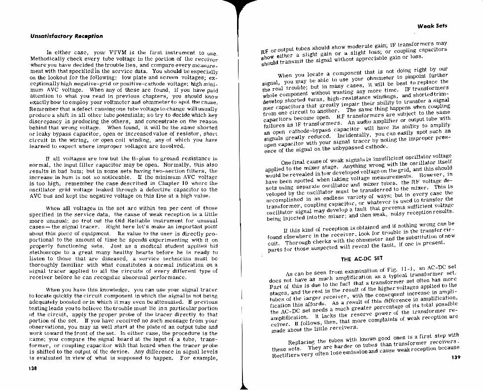
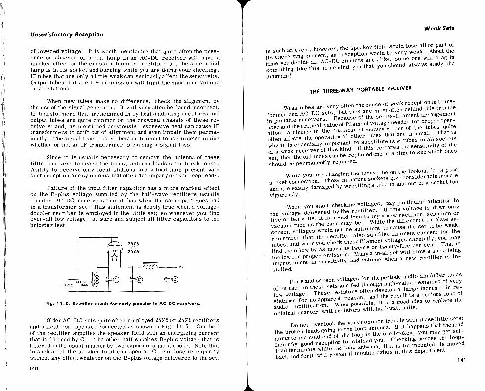
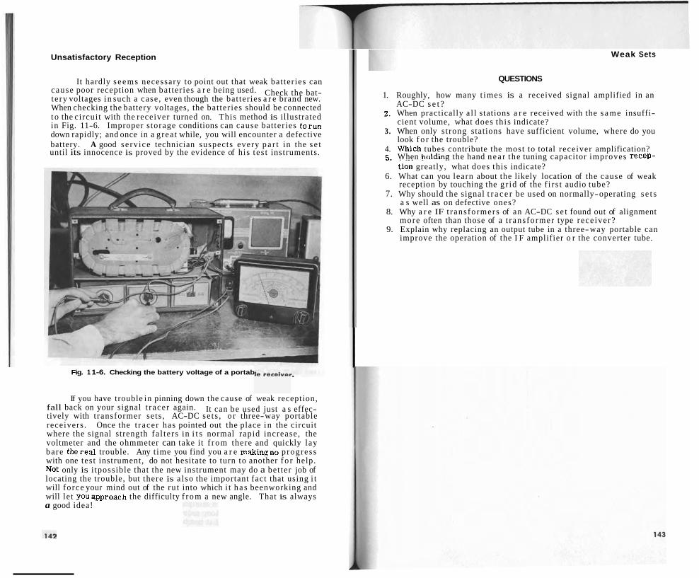
Unsatisfactory Reception
It hardly s e e m s necessary to point out that weak bat ter ies can cause poor reception when bat ter ies a r e being used. Check the bat- te ry voltages i n such a case, even though the bat ter ies a r e brand new. When checking the battery voltages, the bat ter ies should be connected t o the circui t with the receiver turned on. This method is illustrated in Fig. 11-6. Improper s torage conditions can cause bat ter ies to run down rapidly; and once in a g rea t while, you will encounter a defective battery. A good se rv ice technician suspects every p a r t in the s e t until its innocence is proved by the evidence of his t es t instruments.
Fig. 1 1-6. Checking the battery voltage of a portab
If you have trouble in pinning down the cause of weak reception, fall back on your signal t racer again. It can be used just a s effec- tively with t ransformer sets , AC-DC se t s , o r three-way portable receivers . Once the t racer has pointed out the place i n the circuit where the signal strength fa l t e r s in i t s normal rapid increase, the voltmeter and the ohmmeter can take it f r o m there and quickly lay bare therea l trouble. Any t ime you find you a r e makingno progress with one test instrument, do not hesitate to turn to another f o r help. Not only is i tpossible that the new instrument may do a bet ter job of locating the trouble, but there is a l so the important fact that using i t will fo rce your mind out of the ru t into which i t h a s beenworking and will le t youapproach the difficulty f r o m a new angle. That is always a good idea!
Weak Sets
QUESTIONS
1. Roughly, how many t imes is a received signal amplified in an AC-DC s e t ?
2, When practically a l l stations a r e received with the s a m e insuffi- cient volume, what does th i s indicate?
3. When only s t rong stations have sufficient volume, where do you look f o r the trouble?
4. VJhich tubes contribute the most to total receiver amplification? 5 When holding the hand n e a r the tuning capacitor improves recep- " . . . - - - - . - -
tion greatly, what does this indicate? 6. What can you learn about the likely location of the cause of weak
reception by touching the gr id of the f i r s t audio tube? 7. Why should the signal t r a c e r be used on normally-operating s e t s
a s well as on defective ones? 8. Why a r e IF t rans formers of an AC-DC s e t found out of alignment
more often than those of a t rans former type rece iver? 9. Explain why replacing an output tube in a three-way portable can
improve the operation of the I F amplifier o r the converter tube.


Intermittents and Miscellaneous Service Problems
a few minutes. If the set gave most trouble during the early evening hours, low line voltage may be needed to touch off the intermittent condition; so try running it onabout 105 volts. I have often had good luck in starting an intermittent condition by running a receiver at 120 volts for about ten minutes and then dropping the line voltage to around 100 volts. This seems to be more effective than keeping the set continuously on either high or low voltage.
When the owner reports the set usually misbehaves during the first few minutes of operation and then settles down and operates normally until it is shut off and allowed to cool down, you know the set must be cool for the intermittent condition to show itself. When the weather is cold, it often helps to leave such a se t outside for an hour o r so before starting to check it; o r you can chill tubes thorough- ly inthe freezing compartment of a refrigerator tomake one of them reveal its intermittent filament. On the other hand, covering up the whole setwith a canvas o r usinga cardboard to block off the ventila- tion louvres will sometimes raise the temperature of a receiver sufficiently to trigger an intermittent condition.
Fig. 12- 1. Cooling a component to check for intermittent trouble.
A wonderful aid to triggering intermittents is General Cement's Spra-Koat Circuit Cooler shown in use in Fig. 12-1. This is simply a pressurized can of comparatively harmless freon gas such a s is used in refrigerators. When the finger;operated valve is depressed, anarrow spray of the gas can be directed on any suspected component. The temperature of that component drops rapidly. The stream of gas is SO cold it will actually freeze the flesh if allowed to play on it a t
Intermittent Loss of Reception
close range; so be careful. Don't spray it on your hand to see how cold i t is, and don't spray it on a hot glass tube envelope. With this gas you can lower the temperature of a single capacitor, resistor, coil, o r connection to room temperature and far below in a matter of seconds while the rest of the set stays warm. If the component chilled is one that operates normally when warm but cuts out when cool, this spray technique will expose the culprit in nothing flat.
any '
tube reac a* n r "I I K
may set t wher mnr
When the owner says the set dies abruptly, you can mark off possibility of filament failure; but that does not mean there isno
trouble. Internal short circuits that develop when the tube hes a certain temperature very frequently cause a sudden loss xeption. In this case, a very gentle tapping of a defective tube restore normal operation when the set has cut off o r cause the
.o quit playing when it is operating normally. Tapping of tubes I searching for an intermittent condition should be done much
...,A e gently than when looking for noisy tubes.
If the cutting out happens with any dependable frequency, it is a good idea to replace all the tubes one at a time to see if you can find one socket in which a new tube causes the condition to stop. If you do, be sure and double-check by replacing the old tube and ob- serving if the intermittent condition returns. The trouble could have been a defective socket connection that was temporarily "cured" by the disturbance caused by pulling the tube from the socket. If you put in all new tubes and the trouble is still present, at least you have eliminated as many possibilities as the set has tubes.
When no sound at all can be heard from the speaker after the se t cuts out, the speaker voice coil may be open. A quick check of this canbe made by connecting the VOM set to read ' I Output" across the voice-coil terminals. If the pointer of the meter stillcontinues to move up and down after the se t stops playing, you can be sure the trouble lies either in the voice coil or the flexible leads to it, and a repair or replacement can be made as explained in Chapter 2.
If none of the tests mentioned up to now have turned up the cause behind the intermittent behavior, it is time to remove the chassis and give it the blitzkreig or all-out treatment. Place the chassis on an unused end of the bench and connect your test equipment as shown in Fig. 12-2. Connect your VOM output meter from the plate of the output tube to ground. Fasten the RF probe of the signal tracer to the plate of the first IF stage. Connect the VTVM set to read negative volts from the AVC bus to ground. Now tune in a station and make a note of the levels of the various indicators attached to the circuit. Then go about your business of repairing other sets.
The instant the set cuts out, rush over to it and rapidly note e readings on the two meters and note if the sound coming from e signal-tracer speaker is as loud as it was. The evidence con-

Intermittents and Miscellaneous Service Proble
tained in these three observations can go a long way toward pin- pointing the locationof the trouble. For example, if all three indicators maintain their same level, the trouble will almost have to be in the secondary of the output transformer,for we already have established that the speaker voice coil was all r,ight.
Fig. 12-2. Test equipment connectbd to an intermittent chassis.
Jf the VOM reading falls to zerb while the other two indicators remain up, this means the trouble must lie in the audio amplifier or output stage. The VTVM set to read AC volts can be connected to the plate of the audio amplifier; the signal-tracer audio probe can be connectedto the grid of the output stage; and the VOM can be switched to readDC plate voltage onthe outputtube. Thenext time the set cuts out, the three indicators will show whether the trouble is an opening primary winding of the output transformer; whether it originates within the output stage; or whether it occurs in the audio amplifier.. With the possibilities narrowed dowfi in this fashion, a few checks with the voltmeter and ohmmeter or the substitution of parts should quickly clear up the difficulty.
I I
their or i he signal - . -.
ginal con from thl
Assume the indicators are back to 3
and that the AVC voltage falls off w!ile t e tracer speaker goes up a bit. This means the, signalis disappearing between the plate of the f i rs t IF tube and the 4VC rectifier. Shifting the sig- nal tracer to other key points inthis c~ircumscribed Brea will usually
I 152 I
Intermittent Loss of Receptior
nail down the trouble to a single part, such a s a defective IF transformer.
As a final illustration, suppose all three indicators fall t o zero when the set cuts out. This clearly shows that the trouble is arising ahead of the plate of the first IF tube. Move the signal tracer probe to the grid of the IF amplifier and connect the VTVM probe to the oscillator grid. The next time the se t cuts out, you will be able to tell if the trouble lies in the oscillator circuit or i f i t is happening in the first IF tube. Lf the VTVM reading stays normal bkt the signal tracer signal falls out, the signal tracer probe can be moved to the grid of the mixer stage to determine whether the difficulty lies in this stage or ahead of it.
,be, such . --
I .d I
I I
I Fig. 12-3. An RF probe for use with a VNM. I I
I
I It might be mentioned here that an auxiliary RF pic a s
d e one shown in Fig. 12-3, when used with the VTVMj will enaale this instrument to follow and measure the signal passing through the RF-IF parts of the receiver as easily as the ordinary AC probe does this in the audio portion. Having such a probe is a great help in cor- n4ring intermittent troubles. I
I I I I Tubes will be found to be the most common cause of sets that
gd dead and comeback to life. On ra re occasions you will1 run across a transformer winding, a filter choke, or a speaker field coil winding thht will open and close; but usually when one of these; opens up, it sthys open. Voice-coil troubles a re fairly common in~these cases. Sometimes it helps to make speaker troubles appear if you move the cone back and forth by handbeyond its normal excursiolis. IF trans- formers will be found guilty of causing this trouble r/ow and then. DBfective tr immers are often at fault. Oscillators that quit inter-
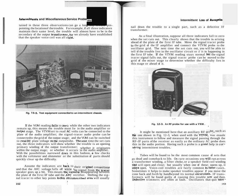
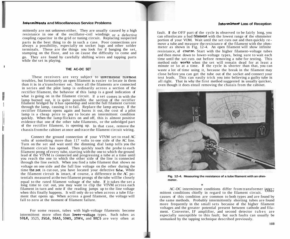
Intermittents and Miscellaneous Service Problems
mittently a re not unknown either. They are usually caused by a high resistance in one of the oscillator-coil windings or a defective coupling capacitor in the grid or tuning circuit. Replacing suspected parts is the best thing to do in such a case. Poor connections are always a possibility, especially on socket lugs and other solder terminals. These a re the things you look for if banging the set , stamping on the floor, and so on cause the difficulty to come and go. They a re found by carefully shifting wires and tapping parts while the set is playing.
I I 1 1 THE AC-DC SET I I
These receivers are very subject to lntermlttent tilament troubles, but fortunately an open filament is easier to locate in them than i t is in a'transformer set. Since all the filaments a re connected
I in ser ies and the pilot lamp is ordinarily across a section of the
1 1 rectifier filament, the behavior of this lamp is a good indication of what is going on in the filament circuit. If a set comes in with the I I lamp burned out, it is quite possible the section of the rectifier
1~
filament bridged by it has openedup and sent the full filament current through the lamp, causing it to fail. Replace the lamp anyway. If the
I rectifier filament opens again and burns it out, the cost of a pilot i I lamp is a cheap price to pay to locate an intermittent condition quickly. When the lamp flickers on and off, this is almost positive evidence that one of the other tube filaments, or the unbridged part of the rectifier filament, is opening up. In that case, remove the
I I chassis fromthe cabinet at once and trace the filament circuit wiring. , I
Connect the ground connection of your VTVM set to read AC volts of something more than 117 volts to one side of the AC line. Turn on the set and wait until the dimming dial lamp tells you the filament circuit has opened. Then quickly touch the probe to each filament prong of every tube, starting with the one to which the ground lead of the VTVM is connected and progressing a tube at a time until you reach the one to which the other side of the line is connected through the line switch. When you find a tube filament that shows no voltage on one side and the full line voltage on the other during the time these t i s cut out, you have located your defective tiube. While the filament circuit is intact, of course, a difference in the AC po- tentials measured at the two filament prongs of the tube will be closely equal to the rated filament voltage of the tube. If it takes the se t a long time to cut out, you may want to clip the VTVM across each filament in turn and note if the reading jumps up to the line voltage when this finally happens. It will only do so when across a tube fila- ment that opens up. When across a good filament, the voltage will fall to zero at the moment of filament failure.
For some reason, tubes with high-voltage filaments become intermittent more often than lower-voltage types. Such tubes as 50L6, 3525, 35L6, 50A5, 50B5, 35W4, and 50C5 are very often at
Intermittent Loss of Reception
fault. If the OFF part of the cycle is observed to be fairly long, you can oftenlocate a bad filament with the lowest range of the ohmmeter portion of your VOM. Wait until the set cuts out and then quickly r e - move a tube and measure the resistance of the filament with the ohm- meter as shown in Fig. 12-4. An open filament will show infinite resistance, of cburse. Start with the higher filament-voltage tubes and then move down to lower-voltage types, being sure to wait each time until the set cuts out before removing a tube for testing. This method only works when the set will remain dead for at least a minute or so at a time. If the cycle is shorter than that, you can waste a lot of time using it, because the break in the filament may close before you can get the tube out of the socket and connect your test leads. This can easily trick you into believing a guilty tube is all right. That is why the first method suggested is usually quicker, even though it does entail removing the chassis from the cabinet.
Fig. 12-4. Measuring the resistance of a tube filament with an ohm- meter.
Y
AC -DC intermittent conditions differ from transformer inter - mittent conditions chiefly in regard to the filament circuit. Other
causes of this condition are common to both types and are found by the same methods. Probably intermittently shorting tubes are found more frequently in the small sets because of the higher filament voltages and the greater potential present between cathode and fila- ment. Converter, IF amplifier, and second detector t u b e s are especially susceptible to this fault; but such faults can usually be unmasked by the tapping technique described previously.

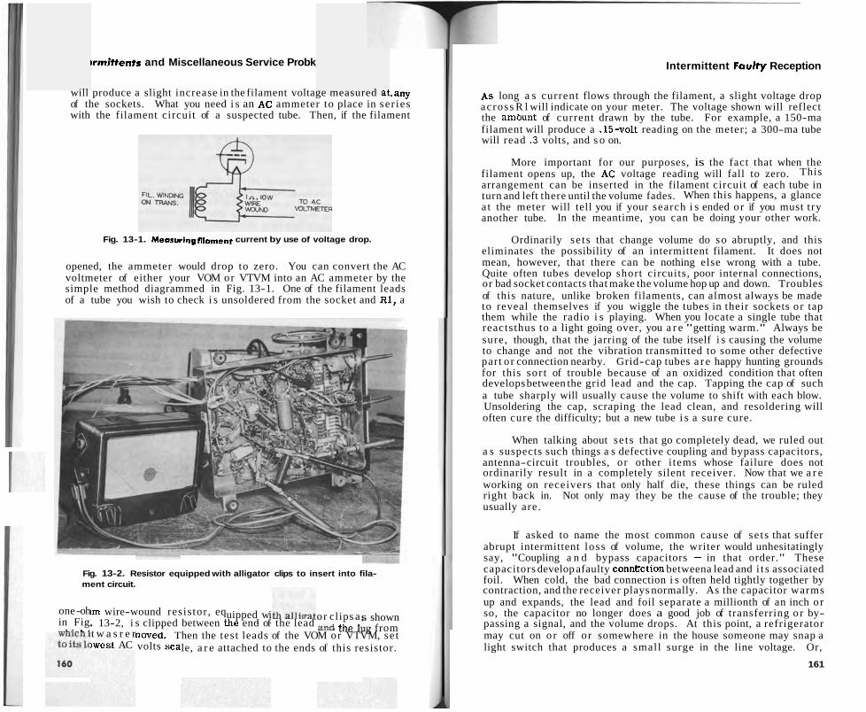
~rmittents and Miscellaneous Service Probk
will produce a slight increase in the filament voltage measured at.any of the sockets. What you need i s an AC ammeter to place in ser ies with the filament circuit of a suspected tube. Then, if the filament
Fig. 13-1. Measuringfilament current by use of voltage drop.
opened, the ammeter would drop to zero. You can convert the AC voltmeter of either your VOM or VTVM into an AC ammeter by the simple method diagrammed in Fig. 13-1. One of the filament leads of a tube you wish to check i s unsoldered from the socket and R1, a
Fig. 13-2. Resistor equipped with alligator clips to insert into fila- ment circuit.
one -oh in Fig ---LI _ L 2
noved. T volts sca
uipped wi - .
or clips a , ,...A &L- 1.
~rn wire-wound resistor , eq s shown . 13-2, i s clipped between tne end of the lead U ~ C lug from t w a s r e r -
hen the test leads of the VOM or VTVM, se t )west AC le, a r e attached to the ends of this resistor.
Intermittent Faulty Reception
As long a s current flows through the filament, a slight voltage drop across R l will indicate on your meter. The voltage shown will reflect the ambunt of current drawn by the tube. For example, a 150-ma filament will produce a .15-volt reading on the meter; a 300-ma tube will read . 3 volts, and s o on.
More important for our purposes, is the fact that when the filament opens up, the AC voltage reading will fall to zero. This arrangement can be inserted in the filament circuit of each tube in turn and left there until the volume fades. When this happens, a glance a t the meter will tell you if your search i s ended or if you must t ry another tube. In the meantime, you can be doing your other work.
Ordinarily se ts that change volume do so abruptly, and this eliminates the possibility of an intermittent filament. It does not mean, however, that there can be nothing else wrong with a tube. Quite often tubes develop short circuits, poor internal connections, or bad socket contacts that make the volume hop up and down. Troubles of this nature, unlike broken filaments, can almost always be made to reveal themselves if you wiggle the tubes in their sockets or tap them while the radio i s playing. When you locate a single tube that reactsthus to a light going over, you a r e "getting warm." Always be sure, though, that the jarring of the tube itself i s causing the volume to change and not the vibration transmitted to some other defective part or connection nearby. Grid-cap tubes a r e happy hunting grounds for this sor t of trouble because of an oxidized condition that often develops between the grid lead and the cap. Tapping the cap of such a tube sharply will usually cause the volume to shift with each blow. Unsoldering the cap, scraping the lead clean, and resoldering will often cure the difficulty; but a new tube i s a sure cure.
When talking about se ts that go completely dead, we ruled out a s suspects such things a s defective coupling and bypass capacitors, antenna-circuit troubles, or other i tems whose failure does not ordinarily result in a completely silent receiver. Now that we a r e working on receivers that only half die, these things can be ruled right back in. Not only may they be the cause of the trouble; they usually are.
If asked to name the most common cause of se ts that suffer abrupt intermittent loss of volume, the writer would unhesitatingly say, "Coupling a n d bypass capacitors - in that order." These capacitors develop afaulty conntction betweena lead and i t s associated foil. When cold, the bad connection i s often held tightly together by contraction, and the receiver plays normally. As the capacitor warms up and expands, the lead and foil separate a millionth of an inch or so, the capacitor no longer does a good job of transferring o r by- passing a signal, and the volume drops. At this point, a refrigerator may cut on o r off or somewhere in the house someone may snap a light switch that produces a small surge in the line voltage. Or,
161
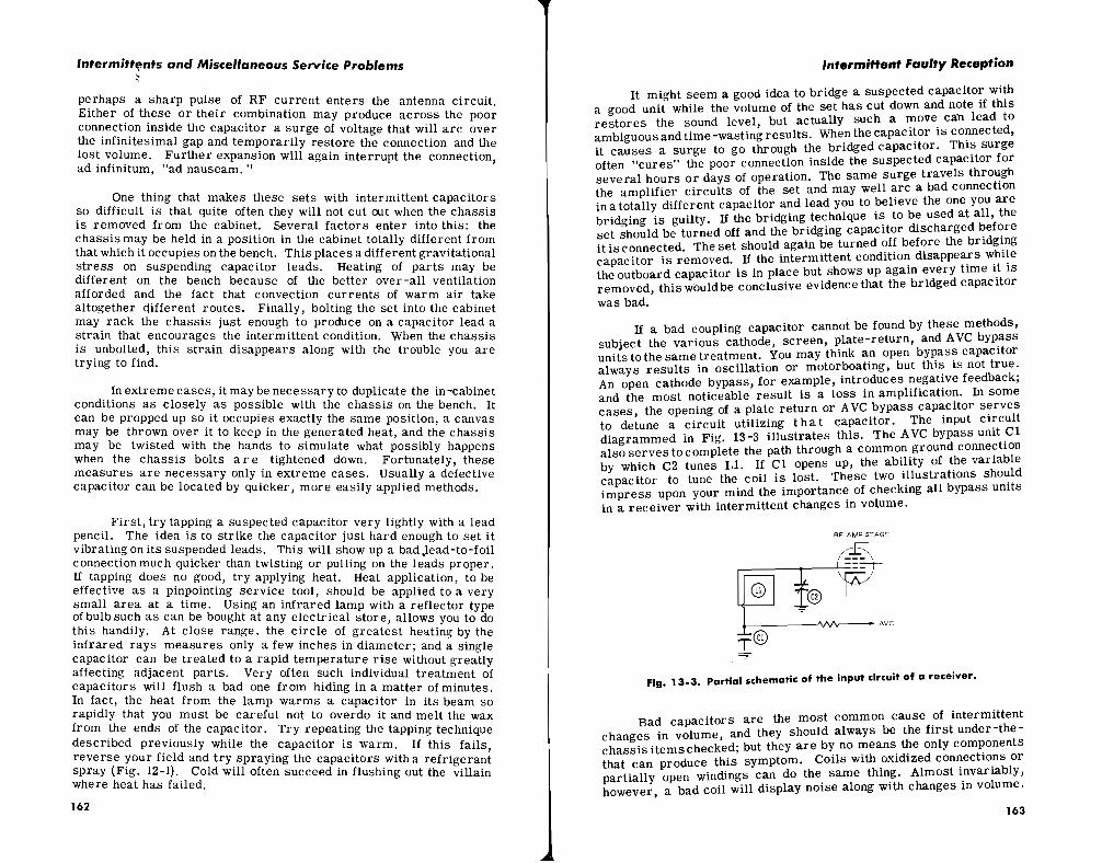
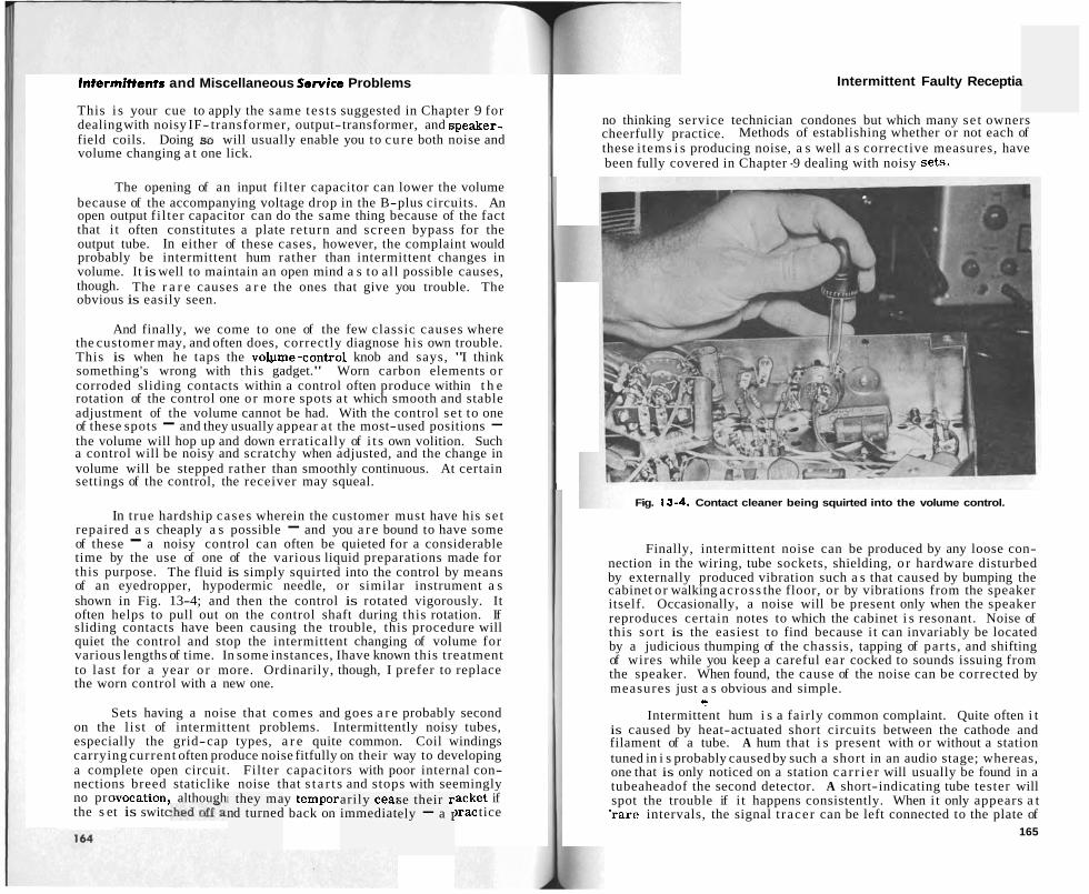
Intermittents and Miscellaneous Sewice Problems
This i s your cue to apply the same tes ts suggested in Chapter 9 for dealing with noisy IF- transformer, output-transformer, and speaker- field coils. Doing SO will usually enable you to cure both noise and volume changing a t one lick.
The opening of an input filter capacitor can lower the volume because of the accompanying voltage drop in the B-plus circuits. An open output f i l ter capacitor can do the same thing because of the fact that i t often constitutes a plate return and screen bypass for the output tube. In either of these cases, however, the complaint would probably be intermittent hum rather than intermittent changes in volume. It is well to maintain an open mind a s to al l possible causes, though. The r a r e causes a r e the ones that give you trouble. The obvious is easily seen.
And finally, we come to one of the few classic causes where the customer may, and often does, correctly diagnose his own trouble. This is when he taps the vobme-control knob and says, "I think something's wrong with this gadget." Worn carbon elements or corroded sliding contacts within a control often produce within t h e rotation of the control one or more spots a t which smooth and stable adjustment of the volume cannot be had. With the control se t to one of these spots - and they usually appear a t the most-used positions - the volume will hop up and down erratically of i t s own volition. Such a control will be noisy and scratchy when adjusted, and the change in volume will be stepped rather than smoothly continuous. At certain settings of the control, the receiver may squeal.
In true hardship cases wherein the customer must have his se t repaired a s cheaply a s possible - and you a r e bound to have some of these - a noisy control can often be quieted for a considerable time by the use of one of the various liquid preparations made for this purpose. The fluid is simply squirted into the control by means of an eyedropper, hypodermic needle, or similar instrument a s shown in Fig. 13-4; and then the control is rotated vigorously. It often helps to pull out on the control shaft during this rotation. If sliding contacts have been causing the trouble, this procedure will quiet the control and stop the intermittent changing of volume for various lengths of time. In some instances, Ihave known this treatment to last for a year or more. Ordinarily, though, I prefer to replace the worn control with a new one.
Sets having a noise that comes and goes a r e probably second on the l is t of intermittent problems. Intermittently noisy tubes, especially the grid-cap types, a r e quite common. Coil windings carrying current often produce noise fitfully on their way to developing a complete open circuit. Filter capacitors with poor internal con- nections breed staticlike noise that s t a r t s and stops with seemingly
)vocation, although ,acket if t is switc 3rac tice
I they ma nd turned
y tempor back on
arily cea: immediat
se their r ely - a 1
no prc the s e
Intermittent Faulty Receptia
no thinking service technician condones but which many se t owners cheerfully practice. Methods of establishing whether or not each of these i tems i s producing noise, a s well a s corrective measures, have been fully covered in Chapter -9 dealing with noisy sets .
Fig. 13-4. Contact cleaner being squirted into the volume control.
Finally, intermittent noise can be produced by any loose con- nection in the wiring, tube sockets, shielding, o r hardware disturbed by externally produced vibration such a s that caused by bumping the cabinet or walking across the floor, or by vibrations from the speaker itself. Occasionally, a noise will be present only when the speaker reproduces certain notes to which the cabinet i s resonant. Noise of this sor t is the easiest to find because i t can invariably be located by a judicious thumping of the chassis, tapping of parts , and shifting of wires while you keep a careful ear cocked to sounds issuing from the speaker. When found, the cause of the noise can be corrected by measures just a s obvious and simple.
'? Intermittent hum i s a fairly common complaint. Quite often i t
is caused by heat-actuated short circuits between the cathode and filament of a tube. A hum that i s present with or without a station tuned in i s probably caused by such a short in an audio stage; whereas, one that is only noticed on a station ca r r i e r will usually be found in a tubeaheadof the second detector. A short-indicating tube tester will spot the trouble if i t happens consistently. When i t only appears a t .rare intervals, the signal t racer can be left connected to the plate of
165

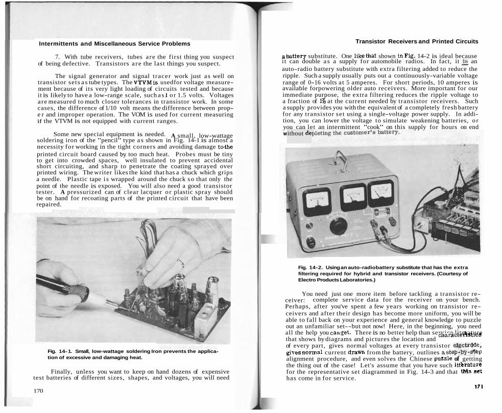
Intermittents and Miscellaneous Service Problems
7. With tube receivers, tubes are the first thing you suspect of being defective. Transistors a re the last things you suspect.
The signal generator and signal tracer work just as well on transistor sets a s tube types. The VTVMis usedfor voltage measure- ment because of its very light loading of circuits tested and because it is Iikely to have a low-range scale, such a s 1 o r 1.5 volts. Voltages are measured to much closer tolerances in transistor work. In some cases, the difference of 1/10 volt means the difference between prop- e r and improper operation. The VOM is used for current measuring if the VTVM is not equipped with current ranges.
Some new special equipment is needed. A small, low-wattage soldering iron of the "pencil" type a s shown in Fig. 14-1 is almost a necessity for working in the tight corners and avoiding damage tothe printed circuit board caused .by too much heat. Probes must be tiny to get into crowded spaces, well insulated to prevent accidental short circuiting, and sharp to penetrate the coating sprayed over printed wiring. The writer likes the kind that has a chuck which grips a needle. Plastic tape i s wrapped around the chuck so that only the point of the needle is exposed. You will also need a good transistor tester. A pressurized can of clear lacquer o r plastic spray should be on hand for recoating parts of the printed circuit that have been repaired.
Fig. 14- 1. Small, low-wattage soldering Iron prevents the applica- tion of excessive and damaging heat.
Finally, unless you want to keep on hand dozens of expensive test batteries of different sizes, shapes, and voltages, you will need
170
Transistor Receivers and Printed Circuits
abattery substitute. One likethat shown inFig. 14-2 is ideal because i t can double a s a supply for automobile radios. In fact, it & an auto-radio battery substitute with extra filtering added to reduce the ripple. Such a supply usually puts out a continuously-variable voltage range of 0-16 volts a t 5 amperes. For short periods, 10 amperes is available forpowering older auto receivers. More important for our immediate purpose, the extra filtering reduces the ripple voltage to a fraction of 1% at the current needed by transistor receivers. Such a supply provides you with the equivalent of a completely fresh battery for any transistor set using a single-voltage power supply. In addi- tion, you can lower the voltage to simulate weakening batteries, o r you can let an intermittent "cook" on this supply for hours on end W ithout dei
Fig. 14-2. Using an auto-radio battery substitute that has the extra filtering required for hybrid and transistor receivers. (Courtesy of Electro Products Laboratories.)
You need just one more item before tackling a transistor re- ceiver: complete service data for the receiver on your bench. Perhaps, after you've spent a few years working on transistor re- ceivers and after their design has become more uniform, you will be able to fall back on your experience and general knowledge to puzzle out an unfamiliar set--but not now! Here, in the beginning, you need all the help you canget. There is no better help than service literature that shows by diagrams and pictures the location and ~ h a r a c t e hits of every part, gives normal voltages at every transistor etpctr&le, givesnormal current d r a m from the battery, outlines astep-b9-#&p alignment procedure, and even solves the Chinese puzzle of getting the thing out of the case! Let's assume that you have such litkrature for the representative set diagrammed in Fig. 14-3 and that tMs se t has come in for service.
I71

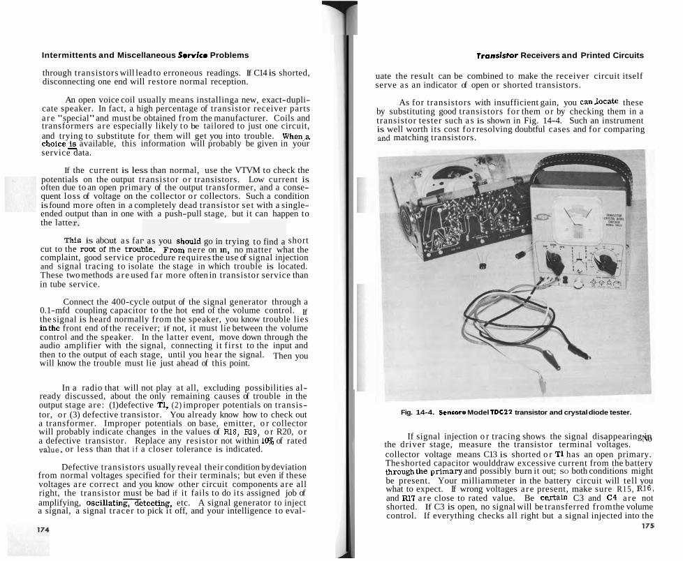
Intermittents and Miscellaneous Sewice Problems
through transistors will lead to erroneous readings. If C14 is shorted, disconnecting one end will restore normal reception.
An open voice coil usually means installinga new, exact-dupli- cate speaker. In fact, a high percentage of transistor receiver parts a re "special" and must be obtained from the manufacturer. Coils and transformers are especially likely to be tailored to just one circuit, and trying to substitute for them will get you into trouble. when,^ c h o i c e 2 available, this information will probably be given in your service data.
If the current is less than normal, use the VTVM to check the potentials on the output transistor o r transistors. Low current is often due to an open primary of the output transformer, and a conse- quent loss of voltage on the collector o r collectors. Such a condition is found more often in a completely dead transistor se t with a single- ended output than in one with a push-pull stage, but i t can happen to the latte
lis is abc - ----L . P
but a s far A. - . - ~ - . - as you s . - ihould go in trying to find a 'I? short
cut to the root 01 me trouDle. From nere on in, no matter what the complaint, good service procedure requires the use of signal injection and signal tracing to isolate the stage in which trouble is located. These two methods a re used fa r more often in transistor service than in tube service.
Connect the 400-cycle output of the signal generator through a 0.1-mfd coupling capacitor to the hot end of the volume control. If the signal is heard normally from the speaker, you know trouble lies inthe front end of the receiver; if not, i t must lie between the volume control and the speaker. In the latter event, move down through the audio amplifier with the signal, connecting i t f irst to the input and then to the output of each stage, until you hear the signal. Then you will know the trouble must lie just ahead of this point.
In a radio that will not play at all, excluding possibilities al- ready discussed, about the only remaining causes of trouble in the output stage are: (1) defective T1, (2) improper potentials on transis- tor, o r (3) defective transistor. You already know how to check out a transformer. Improper potentials on base, emitter, o r collector will probably indicate changes in the values of R18, Rl9, o r R20, o r a defective transistor. Replace any resistor not within 1% of rated
or less than that i f a closer tolerance is indicated.
Defective transistors usually reveal their condition by deviation from normal voltages specified for their terminals; but even if these voltages are correct and you know other circuit components are all right, the transistor must be bad if it fails to do i ts assigned job of amplifying, o ~ c i l l a t i n ~ e t e c t i n ~ , etc. A signal generator to inject a signal, a signal tracer to pick i t off, and your intelligence to eval-
Transistor Receivers and Printed Circuits
uate the result can be combined to make the receiver circuit itself serve as an indicator of open or shorted transistors.
As for transistors with insufficient gain, you canJocate these by substituting good transistors for them or by checking them in a transistor tester such a s is shown in Fig. 14-4. Such an instrument is well worth its cost fo r resolving doubtful cases and for comparing and matching transistors.
Fig. 14-4. Sencore Model TDC22 transistor and crystal diode tester.
If signal injection o r tracing shows the signal disappearing in the driver stage, measure the transistor terminal voltages.
No
collector voltage means C13 is shorted o r T1 has an open primary. The shorted capacitor woulddraw excessive current from the battery throughthe primary and possibly burn it out; SO both conditions might be present. Your milliammeter in the battery circuit will tell you what to expect. If wrong voltages a re present, make sure R15, RIB, and Rl l a re close to rated value. Be certain C3 and C4 a re not shorted. If C3 is open, no signal will be transferred from the volume control. If everything checks all right but a signal injected into the
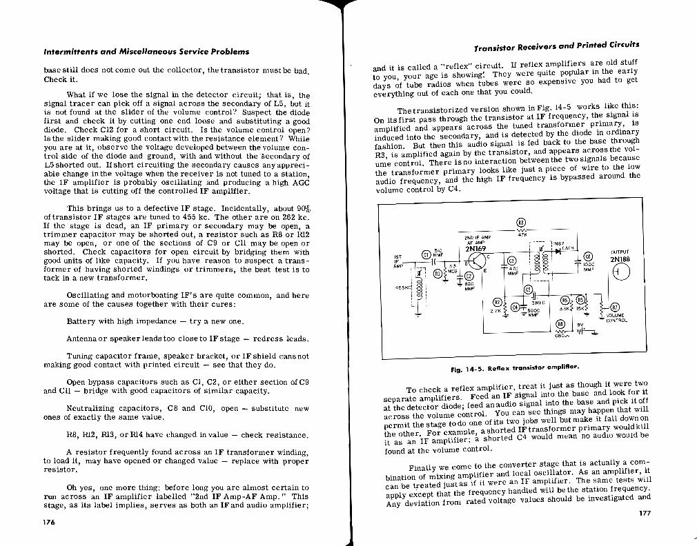
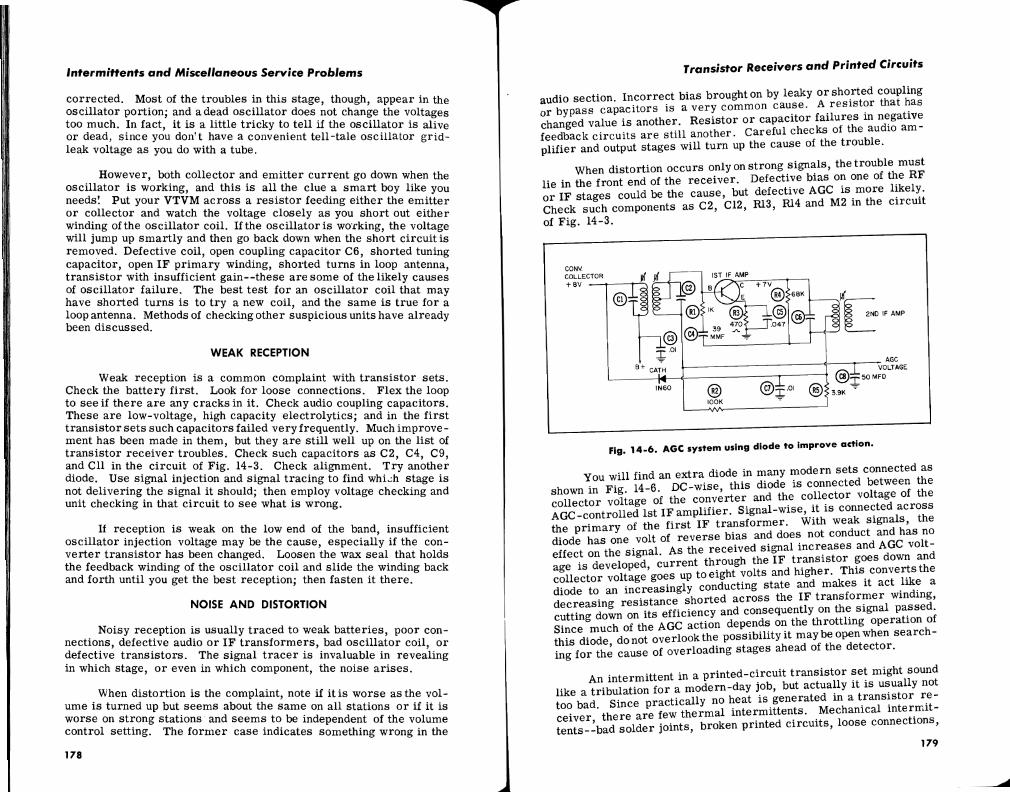


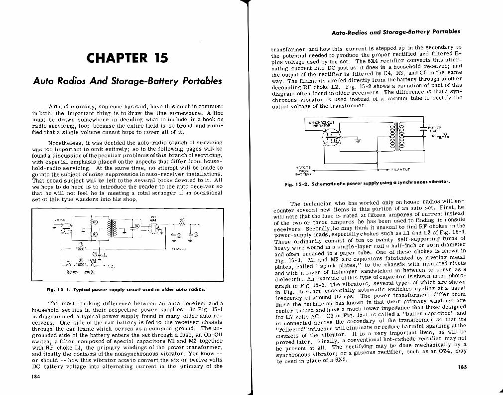
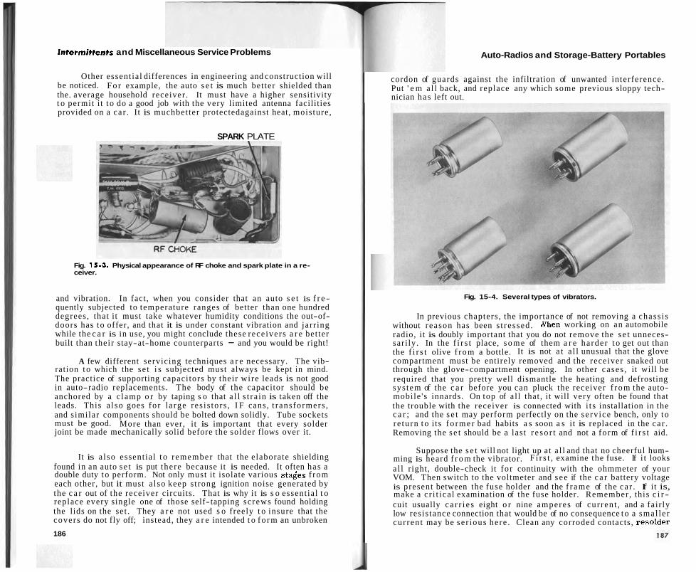
Intermittents and Miscellaneous Service Problems
Other essent ial differences in engineering and construction will be noticed. F o r example, the auto s e t is much bet ter shielded than the. average household receiver . It must have a higher sensitivity t o permit it t o do a good job with the very limited antenna facilities provided on a ca r . It is muchbet ter protectedagainst heat, moisture,
SPARK PLATE
Fig. 15-3. Physical appearance of RF choke and spark plate in a re- ceiver.
and vibration. In fact, when you consider that an auto s e t is f r e - quently subjected to temperature ranges of better than one hundred degrees, that it must take whatever humidity conditions the out-of- doors has t o offer, and that it is under constant vibration and jarr ing while the c a r is in use, you might conclude these rece ivers a r e bet ter built than their stay-at-home counterparts - and you would be right!
A few different servicing techniques a r e necessary. The vib- ration t o which the se t i s subjected must always be kept in mind. The practice of supporting capaci tors by their wi re leads is not good in auto-radio replacements. The body of the capacitor should be anchored by a c lamp o r by taping s o that a l l s t ra in is taken off the leads. This a l so goes fo r l a rge res i s to rs , I F cans, t rans formers , and s imilar components should be bolted down solidly. Tube sockets must be good. More than ever, i t is important that every solder joint be made mechanically solid before the solder flows over it.
It is a l so essent ial t o remember that the elaborate shielding found in an auto s e t is put there because it is needed. It often has a double duty t o perform. Not only must it isolate various s t a i e s f rom each other, but it must a l so keep s trong ignition noise generated by the c a r out of the receiver circuits. That is why it is s o essent ial t o replace every single one of those self-tapping sc rews found holding the lids on the set . They a r e not used s o freely t o insure that the covers do not fly off; instead, they a r e intended t o f o r m an unbroken
186
Auto-Radios and Storage-Battery Portables
cordon of guards against the infiltration of unwanted interference. Put ' e m a l l back, and replace any which some previous sloppy tech- nician has left out.
Fig. 15-4. Several types of vibrators.
In previous chapters , the importance of not removing a chass i s without reason has been s t ressed . a h e n working on an automobile radio, it is doubly important that you do not remove the s e t unneces- sar i ly . In the f i r s t place, s o m e of them a r e harder t o get out than the f i r s t olive f r o m a bottle. It is not a t a l l unusual that the glove compartment must be entirely removed and the receiver snaked out through the glove-compartment opening. In other cases , it will be required that you pretty well dismantle the heating and defrosting sys tem of the c a r before you can pluck the receiver f r o m the auto- mobile 's innards. On top of a l l that, i t will very often be found that the trouble with the receiver is connected with i t s installation in the c a r ; and the s e t may perform perfectly on the se rv ice bench, only t o re tu rn t o i ts f o r m e r bad habits a s soon a s it is replaced in the ca r . Removing the s e t should be a last r e s o r t and not a fo rm of f i r s t aid.
Suppose the s e t will not light up at a l l and that no cheerful hum- ming is heard f r o m the vibrator. F i r s t , examine the fuse. If i t looks a l l right, double-check it fo r continuity with the ohmmeter of your VOM. Then switch to the voltmeter and s e e if the c a r battery voltage is present between the fuse holder and the f r a m e of the ca r . If it is, make a c r i t i ca l examination of the fuse holder. Remember, this c i r - cuit usually c a r r i e s eight o r nine amperes of cur ren t , and a fair ly low resis tance connection that would be of no consequence t o a smal le r cur ren t may be se r ious here . Clean any corroded contacts, resolder

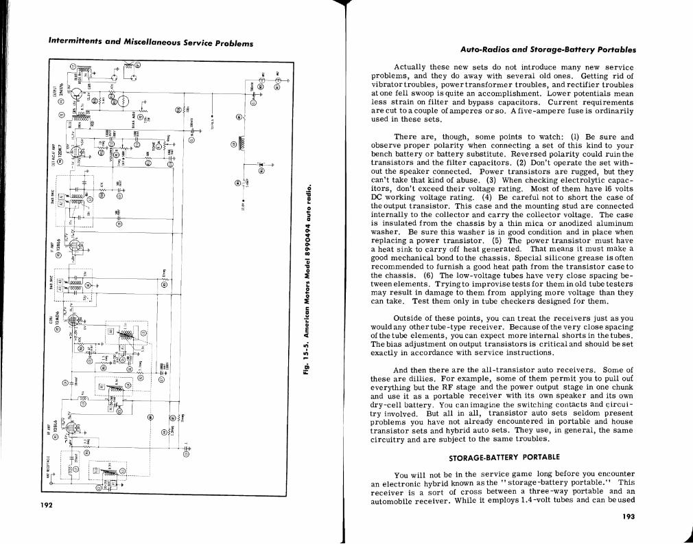
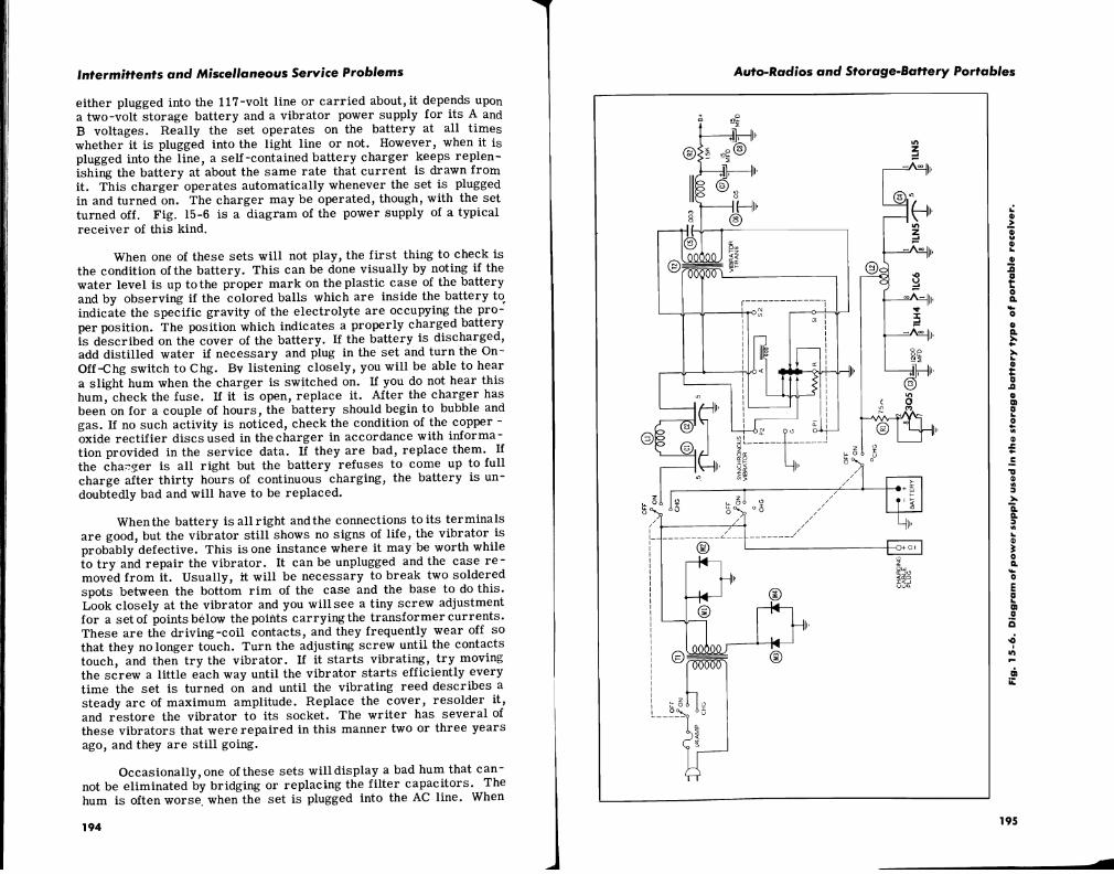
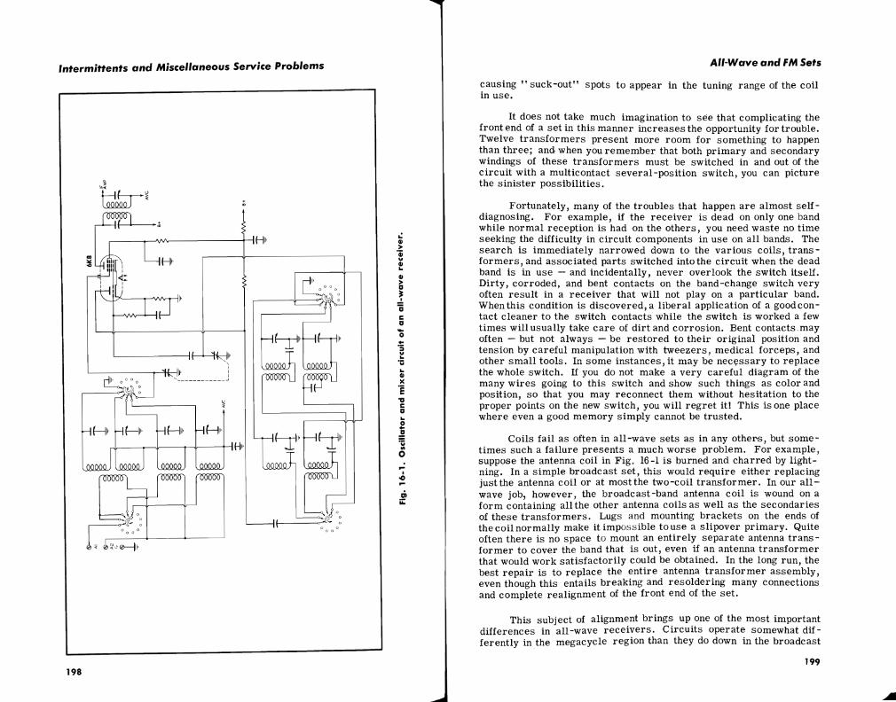
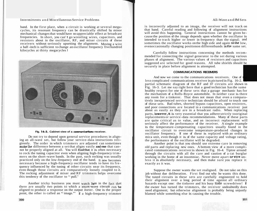
Intermittents a n d Miscellaneous Service Problems
band. In the f i rs t place, when a circuit is working at several mega- cycles, its resonant frequency can be drastically shifted by minor mechanical changes that would have no appreciable effect at broadcast frequencies. In short, you can' t go wrestling wires, capacitors, and resistors about in the oscillator, RF, and mixer circuits of these receivers without seriously upsetting the alignment. Moving a wire a half -inch is sufficient to change an oscillator frequency five hundred kilocycles at thirty megacycles 1
Fig. 16-2. Cabinet view of a comrnunlcarions receiver.
Do not try to depend upon general service procedures in align- ing an all-wave set, but follow your service-data instructions reli- giously. The order in which tr immers are adjusted can sometimes makethe difference between a set that aligns easily andone that can- not be properly aligned at all. You will findthat it is often necessary to rock the tuning capacitor even when aligning high-frequency tr im- mers on the short-wave bands. In the past, such rocking was usually practiced only on the low-frequency end of the band. It now becomes necessary because a high-frequency oscillator tends to have its f re- quency influenced by the tuning of other circuits near its frequency, even though those circuits are comparatively loosely coupled to it. The rocking adjustment of mixer and RF trimmers helps overcome this tendency of the oscillator to " pull.''
watch lic I.-.& -... " fact th
:+ "m.. 1
Another tricky business you must ?s in the at there are usually two points to which a sl l .vl~-wd~e circulr oe aligned to produce a response on the output meter. One is the proper point, the other is called an l 1 image." If a high-frequency trimmer
All-Wave a n d FM Sets
is incorrectly adjusted to an image, the receiver will not track on that band. Careful reading and following of alignment instructions will avoid this happening. General instructions cannot be given be- cause the position of the image depends upon whether the oscillator is intended to track higher or lower in frequency than the signal; and sometimes the oscillator works on the high side and again onthe low, evenoccasionally changing positionon differentbands inthe same set.
Carefully follow instructions concerning the methods recom- mended for connecting the signal generator to the set during various phases of alignment. The various values of resistors and capacitors suggested are selected for good reasons. All tube shields should be securely in place before alignment is attempted.
COMMUNICATIONS RECEIVERS
And now we come to the communications receivers. One of the less complicated communications receiver is pictured in Fig. 16-2. A partial schematic diagram of the RF and IF circuits are shown in Fig. 16-3. Let me say right here that a good technician has the same healthy respect for one of these sets that a garage mechanic has for the mechanism of a Rolls-Royce automobile. In neither case is there any room for a tinkerer. That does not mean that even a compara- tively inexperienced service technician should be afraid to touch one of these sets. Bad tubes, shorted bypass capacitors, open resistors, and poor connections a re located in a communications receiver just about as easily as they are in a broadcast radio. When replacing parts, however,it is very essential that you adhere strictly tooriginal replacements or service -data recommendations. Many of these parts a re quite critical as to value, and an incorrect replacement will seriously affect the performance of the receiver. A single example is the temperature-compensating capacitors usually found in the oscillator circuit to overcome temperature-produced changes in oscillator frequency. If one of these is replaced with an ordinary mica unit, even though it is of the same capacity and voltage rating, the performance of the oscillator will be degraded.
Another point is that you should use extreme care in removing old parts and replacing new ones. A bottom view of a more compli- cated communications receiver is shown in Fig. 16-4. Tiptoe around through the circuits with all the care and caution of a cat burglar working in the home of an insomniac. Never move apar t orwire un- less i t is absolutely necessary, and then make sure you replace i t exactly a s it was.
Suppose the owner wants the set realigned. Do not take on this job without due deliberation. Fi rs t find out why he wants this done. The tuned circuits in these sets are carefully engineered to hold their alignment over a long period of time against all ordinary hazards except one: the tinkerer and his busy little screwdriver! If the owner has turned the trimmers, the receiver undoubtedly does need alignment; but otherwise alignment is probably being unjustly blamed while something else is causing the trouble.
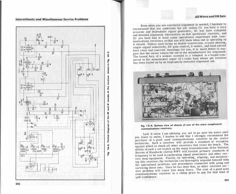
Fig
. 16-3
. P
art
ial
dia
gra
m o
f th
e R
F a
nd
IF
cir
cuits
of
the
receiv
er
sh
ow
n i
n F
ig.
16-2
.

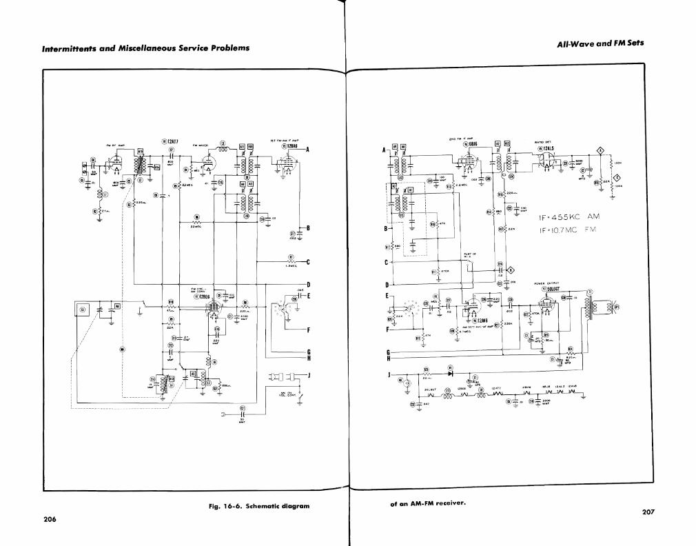
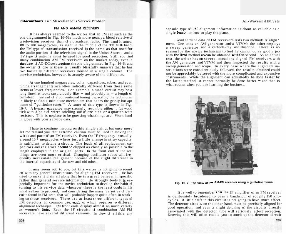
Intermittents a n d Miscellaneous Service Problen
FM AND AM-FM RECEIVERS
It has always seemed to the writer that an FM set such as the one diagrammed in Fig. 16-5 is much more nearly a blood relative of a television receiver than of a broadcast radio. The band it tunes, 88 to 108 megacycles, is right in the middle of the TV VHF band; the FM type of transmission received is the same as that used for the audio portion of the television signal in the United States; and a TV type of antenna must be used for good reception. Still, you find many combination AM-FM receivers on the market today, even in theform of AC-DC sets suchas the one diagrammed in Fig. 16-6; and the owner of one of these i s usually blissfully unaware that he has two basically different receivers housed in a single cabinet. The service technician, however, is acutely aware of the difference.
At one hundred megacycles, coils, capacitors, tubes, and even tuning arrangements are often radically different from these same items at lower frequencies. For example, a tuned circuit may be a long line that looks suspiciously like - and probably is - a length of twin-lead. Instead of a conventional tuning capacitor, the technician is likely to find a miniature mechanism that bears the grisly but apt name of "guillotine tuner." A tuner of this type is shown in Fig. 16-7. A bypass capacitoi may strongly resemble eiiher a fat wood tick with a pair of wires sticking out of one side or a quarter-watt resistor. This i s no place to be guessing what things are. Work hand in glove with your service data.
I hate to continue harping on this single string, but once more let me remind you that extreme caution must be used in moving the wires and parts of an FM receiver. Even the IF frequency is usually around 10.7 megacycles where just a little change in stray capacity is sufficient to detune a circuit. The leads of all replacement ca- pacitors and resistors shouldbe clipped as closely as possible to the length employed in the original parts. In the front end of the set , things a re even more critical. Changing oscillator tubes will f re- quently necessitate realignment because of the slight difference in the internal capacities of the new and old tubes.
It may seem odd to you, but this writer is not going to sound off with any general instructions for aligning FM receivers. He has tried to make it plain all along that he i s a great believer in specific rather than general service information. He strongly feels it is es- pecially important for the novice technician to develop the habit of turning to his service data whenever there is the least doubt in his mind as how to proceed; and considering the many varieties of c i r - cuits found in FM sets, that will probably happen quite often in work- ing on these receivers. There a r e at least three different types of FM detectors in common use, .each of which requires a. different alignment technique. FM front ends display almost a s much variety a s women's h'ats. Even the IF circuits of combination AM-FM receivers have several different versions. In view of all this, any
All-Wave a n d FM Sets
capsule type of FhI alignment information i s about as valuable a s a single lessoIi on how to play the piano.
Good service data on FM receivers lists two methods of align - ment. One uses an AM generator and a VTVM; the other employs a sweep generator and a cathode-ray oscilloscope. There i s no reason for the novice technician to feel he cannot do a s good a job with thefirst method ascan be obtained withthe second. As an actual test , the writer has on several occasions aligned FM receivers with the AM generator and VTVM and then inspected the results with a sweep generator and scope. In every case where the alignment in- structions were conscientiously followed, the results obtained could not be appreciably bettered with the more complicated and expensive instruments. While the alignment can admittedly be done faster by the latter 'method, it cannot normally be done better - and that is what counts when you a re learning the business.
Fig. 16-7. Top view of 1 m AM-FM receiver using a guillotine tuner.
It i s well to remember rnat the IF amplifier of an FM receiver is deliberately broadened to pass a bandwidth of roughly 150 kilo- cycles. A little drift in this circuit is not going to have much effect. The detector circuit, on the other hand, must be precisely aligned for good operation, and even a slight detuning of the circuits directly associated with the detector tube will seriously affect reception. Knowing this will often enable you to touch up the detector-circuit


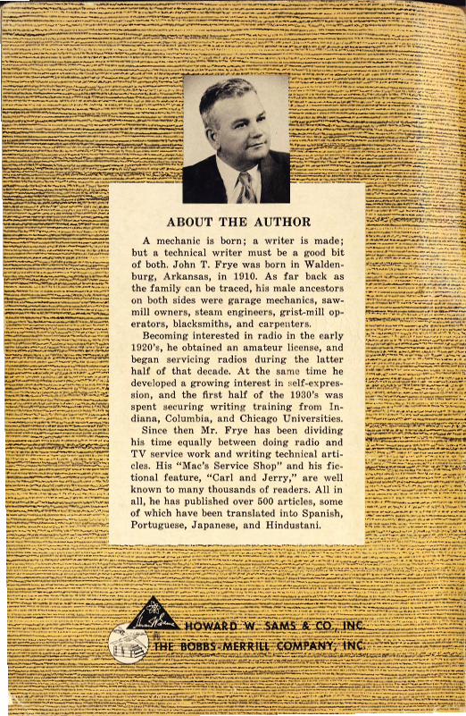


![¨ íð GJ aJ#SS 8 1 7 #1 1#8 N · The Quickest & Easiest Way To [desired result] ex: The Quickest & Easiest Way to Organize Your Closet, The Quickest and Easiest Way to Manifest](https://img.pdfslide.us/doc/110x75/5f81e3c9ba2c4407db7bc952/-gj-ajss-8-1-7-1-18-n-the-quickest-easiest-way-to-desired-result.jpg)