Embed Size (px)
Citation preview
English- 1
Preface Thank you for choosing DELTA’s high-performance VFD-E Series. The VFD-E Series is manufactured with high-quality components and materials and incorporate the latest microprocessor technology available.
Getting Started This quick start will be helpful in the installation and parameter setting of the AC motor drives. To guarantee safe operation of the equipment, read the following safety guidelines before connecting power to the AC motor drives. For detail information, refer to the VFD-E User Manual on the CD supplied with the drive.
DANGER!
1. AC input power must be disconnected before any wiring to the AC motor drive is made. 2. A charge may still remain in the DC-link capacitors with hazardous voltages, even if the power has
been turned off. To prevent personal injury, please ensure that power has turned off before opening the AC motor drive and wait ten minutes for the capacitors to discharge to safe voltage levels.
3. Never reassemble internal components or wiring. 4. The AC motor drive may be destroyed beyond repair if incorrect cables are connected to the
input/output terminals. Never connect the AC motor drive output terminals U/T1, V/T2, and W/T3 directly to the AC mains circuit power supply.
5. Ground the VFD-E using the ground terminal. The grounding method must comply with the laws of the country where the AC motor drive is to be installed. Refer to the Basic Wiring Diagram.
6. VFD-E series is used only to control variable speed of 3-phase induction motors, NOT for 1-phase motors or other purpose.
7. VFD-E series is the specific drive for the elevator door and other automatic door control, NOT for those devices that may cause personal injury, such as life support equipment or any life safety situation.
8. To prevent drive damage, the RFI jumper connected to ground shall be cut off if the AC motor drive is installed on an ungrounded power system or a high resistance-grounded (over 30 ohms) power system or a corner grounded TN system.
WARNING!
1. DO NOT use Hi-pot test for internal components. The semi-conductor used in AC motor drive easily damage by high-pressure.
2. There are highly sensitive MOS components on the printed circuit boards. These components are especially sensitive to static electricity. To prevent damage to these components, do not touch these components or the circuit boards with metal objects or your bare hands.
3. Only quality person is allowed to install, wire and maintain AC motor drive.
CAUTION!
1. Some parameters settings can cause the motor to run immediately after applying power. 2. DO NOT install the AC motor drive in a place subjected to high temperature, direct sunlight, high
humidity, excessive vibration, corrosive gases or liquids, or airborne dust or metallic particles. Only use AC motor drives within specification. Failure to comply may result in fire, explosion or electric shock. To prevent personal injury, please keep children and unqualified people away from the equipment.
3. When the motor cable between AC motor drive and motor is too long, the layer insulation of the motor may be damaged. Please use a frequency inverter duty motor or add an AC output reactor to prevent damage to the motor. Refer to appendix B Reactor for details.
4. The rated voltage for AC motor drive must be ≤240V and the mains supply current capacity must be ≤5000A RMS.
English- 2
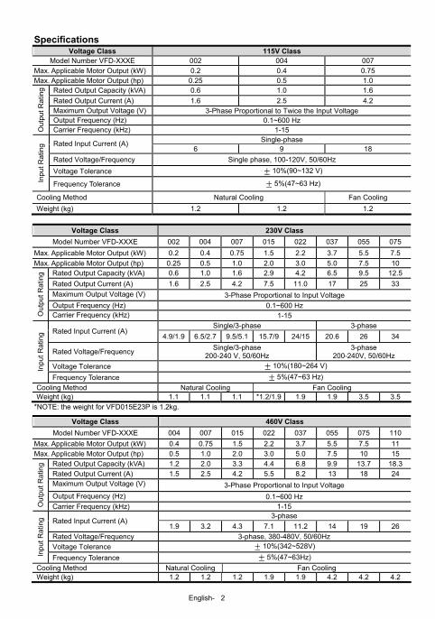
Specifications Voltage Class 115V Class
Model Number VFD-XXXE 002 004 007 Max. Applicable Motor Output (kW) 0.2 0.4 0.75 Max. Applicable Motor Output (hp) 0.25 0.5 1.0
Rated Output Capacity (kVA) 0.6 1.0 1.6 Rated Output Current (A) 1.6 2.5 4.2 Maximum Output Voltage (V) 3-Phase Proportional to Twice the Input Voltage Output Frequency (Hz) 0.1~600 Hz
Out
put R
atin
g
Carrier Frequency (kHz) 1-15 Single-phase Rated Input Current (A)
6 9 18 Rated Voltage/Frequency Single phase, 100-120V, 50/60Hz Voltage Tolerance ± 10%(90~132 V)
Inpu
t Rat
ing
Frequency Tolerance ± 5%(47~63 Hz)
Cooling Method Natural Cooling Fan Cooling Weight (kg) 1.2 1.2 1.2
Voltage Class 230V Class Model Number VFD-XXXE 002 004 007 015 022 037 055 075
Max. Applicable Motor Output (kW) 0.2 0.4 0.75 1.5 2.2 3.7 5.5 7.5 Max. Applicable Motor Output (hp) 0.25 0.5 1.0 2.0 3.0 5.0 7.5 10
Rated Output Capacity (kVA) 0.6 1.0 1.6 2.9 4.2 6.5 9.5 12.5 Rated Output Current (A) 1.6 2.5 4.2 7.5 11.0 17 25 33 Maximum Output Voltage (V) 3-Phase Proportional to Input Voltage Output Frequency (Hz) 0.1~600 Hz
Out
put R
atin
g
Carrier Frequency (kHz) 1-15 Single/3-phase 3-phase
Rated Input Current (A) 4.9/1.9 6.5/2.7 9.5/5.1 15.7/9 24/15 20.6 26 34
Rated Voltage/Frequency Single/3-phase 200-240 V, 50/60Hz
3-phase 200-240V, 50/60Hz
Voltage Tolerance ± 10%(180~264 V) Inpu
t Rat
ing
Frequency Tolerance ± 5%(47~63 Hz) Cooling Method Natural Cooling Fan Cooling Weight (kg) 1.1 1.1 1.1 *1.2/1.9 1.9 1.9 3.5 3.5
*NOTE: the weight for VFD015E23P is 1.2kg.
Voltage Class 460V Class Model Number VFD-XXXE 004 007 015 022 037 055 075 110
Max. Applicable Motor Output (kW) 0.4 0.75 1.5 2.2 3.7 5.5 7.5 11 Max. Applicable Motor Output (hp) 0.5 1.0 2.0 3.0 5.0 7.5 10 15
Rated Output Capacity (kVA) 1.2 2.0 3.3 4.4 6.8 9.9 13.7 18.3 Rated Output Current (A) 1.5 2.5 4.2 5.5 8.2 13 18 24 Maximum Output Voltage (V) 3-Phase Proportional to Input Voltage Output Frequency (Hz) 0.1~600 Hz
Out
put R
atin
g
Carrier Frequency (kHz) 1-15 3-phase
Rated Input Current (A) 1.9 3.2 4.3 7.1 11.2 14 19 26
Rated Voltage/Frequency 3-phase, 380-480V, 50/60Hz Voltage Tolerance ± 10%(342~528V)
Inpu
t Rat
ing
Frequency Tolerance ± 5%(47~63Hz) Cooling Method Natural Cooling Fan Cooling Weight (kg) 1.2 1.2 1.2 1.9 1.9 4.2 4.2 4.2
English- 3
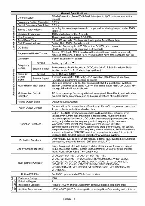
General Specifications
Control System SPWM(Sinusoidal Pulse Width Modulation) control (V/f or sensorless vector control)
Frequency Setting Resolution 0.01Hz Output Frequency Resolution 0.01Hz
Torque Characteristics Including the auto-torque/auto-slip compensation; starting torque can be 150% at 3.0Hz
Overload Endurance 150% of rated current for 1 minute Skip Frequency Three zones, setting range 0.1-600Hz Accel/Decel Time 0.1 to 600 seconds (2 Independent settings for Accel/Decel time) Stall Prevention Level Setting 20 to 250% of rated current
DC Brake Operation frequency 0.1-600.0Hz, output 0-100% rated current Start time 0-60 seconds, stop time 0-60 seconds
Regenerated Brake Torque Approx. 20% (up to 125% possible with optional brake resistor or externally mounted brake unit, 1-15hp (0.75-11kW) models have brake chopper built-in)
Con
trol C
hara
cter
istic
s
V/f Pattern 4-point adjustable V/f pattern
Keypad Setting by Frequency Setting External Signal Potentiometer-5kΩ/0.5W, 0 to +10VDC, 4 to 20mA, RS-485 interface; Multi-
function Inputs 3 to 9 (15 steps, Jog, up/down) Keypad Set by RUNand STOP Operation
Setting Signal External Signal 2 wires/3 wires ((MI1, MI2, MI3)), JOG operation, RS-485 serial interface
(MODBUS), programmable logic controller
Multi-function Input Signal Multi-step selection 0 to 15, Jog, accel/decel inhibit, 2 accel/decel switches, counter, , external Base Block, ACI/AVI selections, driver reset, UP/DOWN key settings, NPN/PNP input selection
Multi-function Output Indication
AC drive operating, frequency attained, zero speed, Base Block, fault indication, overheat alarm, emergency stop and status selections of input terminals O
pera
ting
Cha
ract
eris
tics
Analog Output Signal Output frequency/current
Alarm Output Contact Contact will be On when drive malfunctions (1 Form C/change-over contact and 1 open collector output) for standard type)
Operation Functions
Built-in PLC(NOT for CANopen models), AVR, accel/decel S-Curve, over-voltage/over-current stall prevention, 5 fault records, reverse inhibition, momentary power loss restart, DC brake, auto torque/slip compensation, auto tuning, adjustable carrier frequency, output frequency limits, parameter lock/reset, vector control, PID control, external counter, MODBUS communication, abnormal reset, abnormal re-start, power-saving, fan control, sleep/wake frequency, 1st/2nd frequency source selections, 1st/2nd frequency source combination, NPN/PNP selection, parameters for motor 0 to motor 3, DEB and OOB (Out Of Balance Detection)(for washing machine)
Protection Functions Over voltage, over current, under voltage, external fault, overload, ground fault, overheating, electronic thermal, IGBT short circuit, PTC
Display Keypad (optional) 6-key, 7-segment LED with 4-digit, 5 status LEDs, master frequency, output frequency, output current, custom units, parameter values for setup and lock, faults, RUN, STOP, RESET, FWD/REV, PLC
Built-in Brake Chopper
VFD002E11T/21T/23T, VFD004E11T/21T/23T/43T, VFD007E21T/23T/43T, VFD015E23T/43T, VFD007E11A, VFD015E21A, VFD022E21A/23A/43A, VFD037E23A/43A VFD007E11C, VFD015E21C, VFD022E21C/23C/43C, VFD037E23C/43C, VFD055E23A/43A, VFD075E23A/43A, VFD110E43A, VFD055E23C/43C, VFD075E23C/43C, VFD110E43C
Built-in EMI Filter For 230V 1-phase and 460V 3-phase models.
Enclosure Rating IP20 Pollution Degree 2 Installation Location Altitude 1,000 m or lower, keep from corrosive gasses, liquid and dust
Env
irom
enta
l C
ondi
tions
Ambient Temperature -10oC to 50oC (40oC for side-by-side mounting) Non-Condensing and not frozen
English- 4
Storage/ Transportation Temperature -20 oC to 60 oC
Ambient Humidity Below 90% RH (non-condensing)
Vibration 9.80665m/s2 (1G) less than 20Hz, 5.88m/s2 (0.6G) at 20 to 50Hz
Approvals
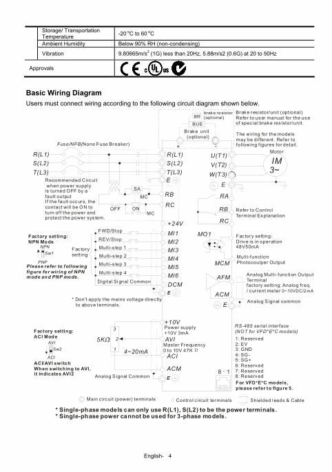
Basic Wiring Diagram Users must connect wiring according to the following circuit diagram shown below.
AVI
ACI
ACM
+
4~20mA
+10V
5K
3
2
1
Power supply+10V 3mA
Master Frequency0 to 10V 47K
Analog S ignal Common E
Main c irc ui t (power) terminals Control c ircuit terminals Shielded l eads & Cable
* Don't apply the mains voltage direc tly to above terminals.
E
R(L1)S(L2)T(L3)
Fuse/NFB(None Fuse Breaker)
SA
OFF ON
MC
MC
RB
RC
Recommended Circui t when power supply is turned OFF by a fault outputIf the fault occurs, thecontact will be ON to turn off the power andprotect the power sys tem.
R(L1)S(L2)T(L3)
E
Analog Mult i- func ti on OutputTerminalfactory setti ng: Analog freq./ cur rent meter 0~10VDC/2 mA
U(T1)V(T2)W(T3)
IM3~
AFM
ACM
RA
RB
RC
Motor
Fac tory sett ing:Drive is in operation48V50mA
Multi-function Photocoulper Output
Analog S ignal common
E
E
Refer to ControlTerminal Explanation
MO1
MCM
MI1MI2MI3MI4
MI6MI5
DCM
+24VFWD/Stop
REV/Stop
Multi-s tep 1
Mult i-s tep 2
Mult i-s tep 3
Mult i-s tep 4
Digital Si gnal Common
Fac torysett ing
Sw2AVI
ACI
Factory setting: ACI Mode
ACI/AVI sw itchWhen switching to AVI,it indicates AVI2
-
8 1
Sw1NPN
PNP
Factory set ting: NPN Mode
Please refer to follow ing figure for wiring of NPNmode and PNP mode.
Brake res istor/unit (optional)Refer to us er manual for the use of spec ial brake res istor/unit.
The wiring for the modelsmay be different. Refer tofollowing f igures for detail.
* Single-phase models can only use R(L1), S(L2) to be the power terminals.* Single-phase power cannot be used for 3-phase models.
BUE
Brake unit (optional)
BRbrake re sistor(opt ional)
RS-485 serial inter face(NOT for VFD*E*C models)1: Reserved 2: EV
5: SG+ 6: Reserved 7: Reserved 8: Reserved
3: GND 4: SG-
For VFD*E*C models, p lease refer to figure 5.
English- 5
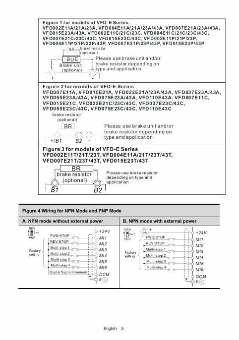
+ -
Please use brake unit and/or brake resi stor depending on type and appli cati on
Brake un it (optional)
BUE
BR brake resis tor(opti onal)
Figure 1 for models of VFD-E SeriesVFD002E11A/21A/23A, VFD004E11A/21A/23A/43A, VFD007E21A/23A/43A, VFD015E23A/43A, V FD002E11C/21C/23C, VFD004E11C/21C/23C/43C, VFD007E21C/23C/43C, VFD015E23C/43C, VFD002E 11P/21P /23P, VFD004E11P /21P/23P/43P, VFD007E21P/23P /43P, VFD015E23P/43P
Please use brak e unit and/or brake resis tor depending on type and application
+/B1 -
brake resis tor (opti onal)
BR
B2
Figure 2 for models of VFD-E SeriesVFD007E11A, V FD015E21A, V FD022E21A/23A/43A, VFD037E23A/43A, VFD055E23A/43A, V FD075E 23A/43A, VFD110E43A, VFD007E11C, VFD015E21C, VFD022E21C/23C/43C, VFD037E23C/43C, VFD055E23C/43C, V FD075E 23C/43C, VFD110E43C
Please use brake resistor depending on type and application
Figure 3 for models of VFD-E SeriesVFD002E11T/21T/23T, VFD004E11A/21T/23T/43T, VFD007E21T/23T/43T, VFD015E23T/43T
B2
BRbrake resistor (optional)
Figure 4 Wiring for NPN Mode and PNP Mode
A. NPN mode without external power B. NPN mode with external power
Factorysetting
NPN
PNP
Factorysetting
NPN
PNP
24Vdc-
+
English- 6
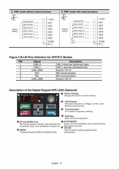
C. PNP mode without external power D. PNP mode with external power
Sw1
Factorysetting
NPN
PNP
Sw1
Factorysetting
NPN
PNP
24Vdc -
+
Figure 5 RJ-45 Pins Definition for VFD*E*C Models
PIN Signal Description 1 CAN_H CAN_H bus line (dominant high) 2 CAN_L CAN_L bus line (dominant low) 3 CAN_GND Ground / 0V /V- 4 SG+ 485 communication 5 SG- 485 communication 7 CAN_GND Ground / 0V /V-
Description of the Digital Keypad KPE-LE02 (Optional)
LED DisplayIndicates frequency, voltage, current, userdefined units and etc.
Status DisplayDisplay the driver's current status.
STOP/RESET
Stops AC drive operation and reset the drive after fault occurred.
RUN KeyStart AC drive operation.
MODEChange between different display mode.
UP and DOWN KeySet the parameter number and changes the numerical data, such as Master Frequency.
PotentiometerFor master Frequency setting.
1
2
3
4
5
6
7
2
3
45
6
7 8
8 ENTERUsed to enter/modify programming parameters
1
English- 7
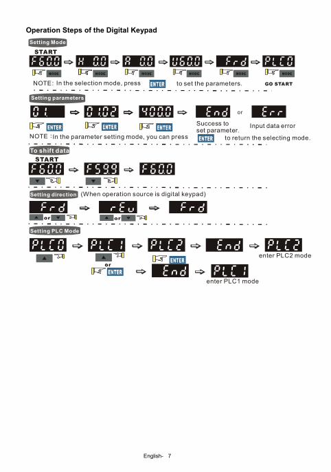
Operation Steps of the Digital Keypad
To shift data
Setting PLC Mode
Setting Mode
Setting direction (When operation source is digital keypad)
START
GO START
enter PLC2 mode
enter PLC1 mode
NOTE:In the parameter setting mode, you can press to return the selecting mode.
NOTE: In the selection mode, press to set the parameters.
Setting parameters
Success to set parameter.
Input data error
or
English- 8
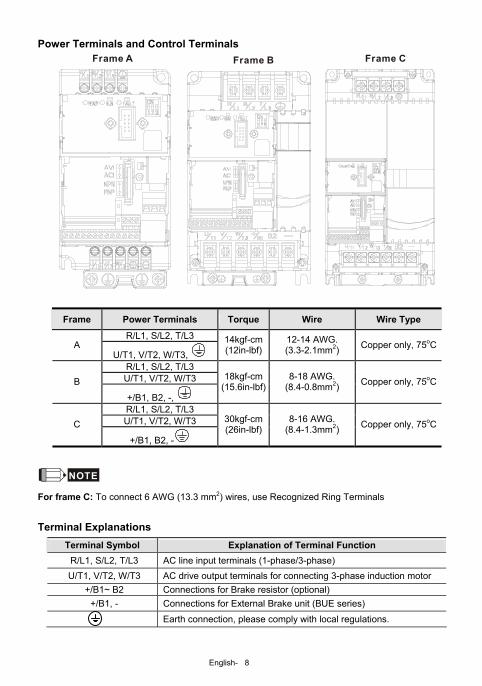
Power Terminals and Control Terminals Frame A Frame B Frame C
Frame Power Terminals Torque Wire Wire Type
R/L1, S/L2, T/L3 A
U/T1, V/T2, W/T3, 14kgf-cm(12in-lbf)
12-14 AWG. (3.3-2.1mm2) Copper only, 75oC
R/L1, S/L2, T/L3 U/T1, V/T2, W/T3 B
+/B1, B2, -,
18kgf-cm(15.6in-lbf)
8-18 AWG. (8.4-0.8mm2) Copper only, 75oC
R/L1, S/L2, T/L3 U/T1, V/T2, W/T3 C
+/B1, B2, -
30kgf-cm(26in-lbf)
8-16 AWG. (8.4-1.3mm2) Copper only, 75oC
NOTE For frame C: To connect 6 AWG (13.3 mm2) wires, use Recognized Ring Terminals
Terminal Explanations Terminal Symbol Explanation of Terminal Function
R/L1, S/L2, T/L3 AC line input terminals (1-phase/3-phase) U/T1, V/T2, W/T3 AC drive output terminals for connecting 3-phase induction motor
+/B1~ B2 Connections for Brake resistor (optional) +/B1, - Connections for External Brake unit (BUE series)
Earth connection, please comply with local regulations.
English- 9
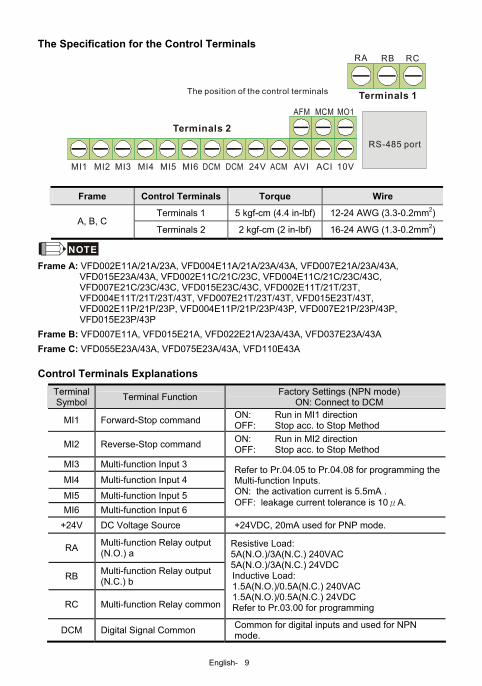
The Specification for the Control Terminals
RS-485 port
10VMI1 MI2 MI3 MI4 MI5 MI6 DCM 24VDCM ACM AVI ACI
AFM MCM MO1
RA RB RC
The position of the control terminals
Terminals 2
Terminals 1
Frame Control Terminals Torque Wire
Terminals 1 5 kgf-cm (4.4 in-lbf) 12-24 AWG (3.3-0.2mm2)A, B, C
Terminals 2 2 kgf-cm (2 in-lbf) 16-24 AWG (1.3-0.2mm2)
NOTE Frame A: VFD002E11A/21A/23A, VFD004E11A/21A/23A/43A, VFD007E21A/23A/43A,
VFD015E23A/43A, VFD002E11C/21C/23C, VFD004E11C/21C/23C/43C, VFD007E21C/23C/43C, VFD015E23C/43C, VFD002E11T/21T/23T, VFD004E11T/21T/23T/43T, VFD007E21T/23T/43T, VFD015E23T/43T, VFD002E11P/21P/23P, VFD004E11P/21P/23P/43P, VFD007E21P/23P/43P, VFD015E23P/43P
Frame B: VFD007E11A, VFD015E21A, VFD022E21A/23A/43A, VFD037E23A/43A Frame C: VFD055E23A/43A, VFD075E23A/43A, VFD110E43A Control Terminals Explanations
Terminal Symbol Terminal Function Factory Settings (NPN mode)
ON: Connect to DCM
MI1 Forward-Stop command ON: Run in MI1 direction OFF: Stop acc. to Stop Method
MI2 Reverse-Stop command ON: Run in MI2 direction OFF: Stop acc. to Stop Method
MI3 Multi-function Input 3
MI4 Multi-function Input 4
MI5 Multi-function Input 5 MI6 Multi-function Input 6
Refer to Pr.04.05 to Pr.04.08 for programming the Multi-function Inputs. ON: the activation current is 5.5mA . OFF: leakage current tolerance is 10μA.
+24V DC Voltage Source +24VDC, 20mA used for PNP mode.
RA Multi-function Relay output (N.O.) a
RB Multi-function Relay output (N.C.) b
RC Multi-function Relay common
Resistive Load: 5A(N.O.)/3A(N.C.) 240VAC 5A(N.O.)/3A(N.C.) 24VDC Inductive Load: 1.5A(N.O.)/0.5A(N.C.) 240VAC 1.5A(N.O.)/0.5A(N.C.) 24VDC Refer to Pr.03.00 for programming
DCM Digital Signal Common Common for digital inputs and used for NPN mode.
English- 10
Terminal Symbol Terminal Function Factory Settings (NPN mode)
ON: Connect to DCM
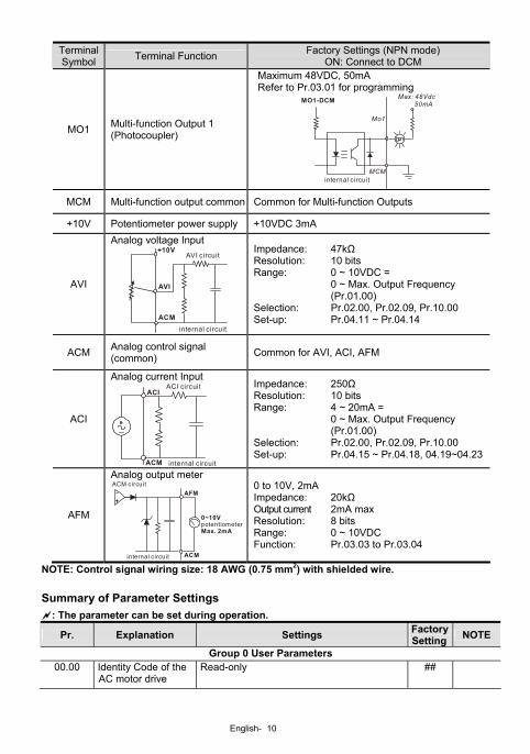
MO1 Multi-function Output 1 (Photocoupler)
Maximum 48VDC, 50mA Refer to Pr.03.01 for programming
MO1-DCM
Mo1
MCM
Max: 48Vdc 50mA
internal circuit
MCM Multi-function output common Common for Multi-function Outputs
+10V Potentiometer power supply +10VDC 3mA
AVI
Analog voltage Input
ACM
AVI
+10V
internal circuit
AVI circuit
Impedance: 47kΩ Resolution: 10 bits Range: 0 ~ 10VDC = 0 ~ Max. Output Frequency
(Pr.01.00) Selection: Pr.02.00, Pr.02.09, Pr.10.00 Set-up: Pr.04.11 ~ Pr.04.14
ACM Analog control signal (common) Common for AVI, ACI, AFM
ACI
Analog current Input
ACM
ACI
internal circuit
ACI circuit
Impedance: 250Ω Resolution: 10 bits Range: 4 ~ 20mA = 0 ~ Max. Output Frequency
(Pr.01.00) Selection: Pr.02.00, Pr.02.09, Pr.10.00 Set-up: Pr.04.15 ~ Pr.04.18, 04.19~04.23
AFM
Analog output meter
AFM
ACM
0~10V
Max. 2mApotentiometer
ACM circuit
internal circuit
0 to 10V, 2mA Impedance: 20kΩ Output current 2mA max Resolution: 8 bits Range: 0 ~ 10VDC Function: Pr.03.03 to Pr.03.04
NOTE: Control signal wiring size: 18 AWG (0.75 mm2) with shielded wire. Summary of Parameter Settings
: The parameter can be set during operation.
Pr. Explanation Settings Factory Setting NOTE
Group 0 User Parameters 00.00 Identity Code of the
AC motor drive Read-only ##
English- 11
Pr. Explanation Settings Factory Setting NOTE
00.01 Rated Current Display of the AC motor drive
Read-only #.#
00.02 Parameter Reset
0: Parameter can be read/written 1: All parameters are read only 6: Clear PLC program (NOT for VFD*E*C models) 9: All parameters are reset to factory settings (50Hz, 230V/400V or 220V/380V depends on Pr.00.12) 10: All parameters are reset to factory settings (60Hz, 220V/440V)
0
00.03 Start-up Display Selection
0: Display the frequency command value (Fxxx) 1: Display the actual output frequency (Hxxx)2: Display the content of user-defined unit (Uxxx) 3: Multifunction display, see Pr.00.04 4: FWD/REV command 5: PLCx (PLC selections: PLC0/PLC1/PLC2) (NOT for VFD*E*C models)
0
00.04 Content of Multi-function Display
0: Display the content of user-defined unit (Uxxx) 1: Display the counter value (c) 2: Display PLC D1043 value (C) (NOT for VFD*E*C models) 3: Display DC-BUS voltage (u) 4: Display output voltage (E) 5: Display PID analog feedback signal value (b) (%) 6: Output power factor angle (n) 7: Display output power (P) 8: Display the estimated value of torque as it relates to current (t) 9: Display AVI (I) (V) 10: Display ACI / AVI2 (i) (mA/V) 11: Display the temperature of IGBT (h) (°C)12: Display AVI3/ACI2 level (I.) 13: Display AVI4/ACI3 level (i.) 14: Display PG speed in RPM (G) 15: Display motor number (M)
0
00.05 User-Defined Coefficient K 0. 1 to 160.0 1.0
00.06 Power Board Software Version
Read-only #.##
00.07 Control Board Software Version
Read-only #.##
00.08 Password Input 0 to 9999 0 00.09 Password Set 0 to 9999 0
00.10 Control Method 0: V/f Control 1: Vector Control 0
00.11 Reserved
English- 12
Pr. Explanation Settings Factory Setting NOTE
00.12 50Hz Base Voltage Selection
0: 230V/400V 1: 220V/380V 0
Group 1 Basic Parameters
01.00 Maximum Output Frequency (Fmax) 50.00 to 600.0 Hz 60.00
01.01 Maximum Voltage Frequency (Fbase) (Motor 0)
0.10 to 600.0 Hz 60.00
220.001.02
Maximum Output Voltage (Vmax) (Motor 0)
115V/230V series: 0.1V to 255.0V 460V series: 0.1V to 510.0V 440.0
01.03 Mid-Point Frequency (Fmid) (Motor 0) 0.10 to 600.0 Hz 1.50
10.0 01.04 Mid-Point Voltage (Vmid) (Motor 0)
115V/230V series: 0.1V to 255.0V 460V series: 0.1V to 510.0V 20.0
01.05 Minimum Output Frequency (Fmin) (Motor 0)
0.10 to 600.0 Hz 1.50
10.0 01.06
Minimum Output Voltage (Vmin) (Motor 0)
115V/230V series: 0.1V to 255.0V 460V series: 0.1V to 510.0V 20.0
01.07 Output Frequency Upper Limit
0.1 to 120.0% 110.0
01.08 Output Frequency Lower Limit
0.0 to100.0 % 0.0
01.09 Accel Time 1 0.1 to 600.0 / 0.01 to 600.0 sec 10.0 01.10 Decel Time 1 0.1 to 600.0 / 0.01 to 600.0 sec 10.0
0.1 to 600.0 / 0.01 to 600.0 sec 10.0 01.11 Accel Time 2 For VFD*E*C models, the factory setting is 1.0 0.1 to 600.0 / 0.01 to 600.0 sec 10.0 01.12 Decel Time 2 For VFD*E*C models, the factory setting is 1.0
01.13 Jog Acceleration Time
0.1 to 600.0 / 0.01 to 600.0 sec 1.0
01.14 Jog Deceleration Time
0.1 to 600.0 / 0.01 to 600.0 sec 1.0
01.15 Jog Frequency 0.10 Hz to Fmax (Pr.01.00) Hz 6.00
01.16
Auto acceleration / deceleration (refer to Accel/Decel time setting)
0: Linear Accel/Decel 1: Auto Accel, Linear Decel 2: Linear Accel, Auto Decel 3: Auto Accel/Decel (Set by load) 4: Auto Accel/Decel (set by Accel/Decel Time setting)
0
01.17 Acceleration S-Curve 0.0 to 10.0 / 0.00 to 10.00 sec 0.0
01.18 Deceleration S-Curve 0.0 to 10.0 / 0.00 to 10.00 sec 0.0
01.19 Accel/Decel Time Unit
0: Unit: 0.1 sec 1: Unit: 0.01 sec 0
01.20 Delay Time at 0Hz for Simple Position
0.00 to 600.00 sec 0.00
English- 13
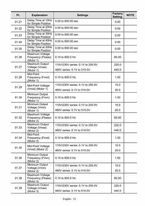
Pr. Explanation Settings Factory Setting NOTE
01.21 Delay Time at 10Hz for Simple Position
0.00 to 600.00 sec 0.00
01.22 Delay Time at 20Hz for Simple Position
0.00 to 600.00 sec 0.00
01.23 Delay Time at 30Hz for Simple Position
0.00 to 600.00 sec 0.00
01.24 Delay Time at 40Hz for Simple Position
0.00 to 600.00 sec 0.00
01.25 Delay Time at 50Hz for Simple Position
0.00 to 600.00 sec 0.00
01.26 Maximum Voltage Frequency (Fbase) (Motor 1)
0.10 to 600.0 Hz 60.00
115V/230V series: 0.1V to 255.0V 220.001.27
Maximum Output Voltage (Vmax) (Motor 1) 460V series: 0.1V to 510.0V 440.0
01.28 Mid-Point Frequency (Fmid) (Motor 1)
0.10 to 600.0 Hz 1.50
115V/230V series: 0.1V to 255.0V 10.0 01.29 Mid-Point Voltage
(Vmid) (Motor 1) 460V series: 0.1V to 510.0V 20.0
01.30 Minimum Output Frequency (Fmin) (Motor 1)
0.10 to 600.0 Hz 1.50
115V/230V series: 0.1V to 255.0V 10.0 01.31
Minimum Output Voltage (Vmin) (Motor 1) 460V series: 0.1V to 510.0V 20.0
01.32 Maximum Voltage Frequency (Fbase) (Motor 2)
0.10 to 600.0 Hz 60.00
115V/230V series: 0.1V to 255.0V 220.001.33
Maximum Output Voltage (Vmax) (Motor 2) 460V series: 0.1V to 510.0V 440.0
01.34 Mid-Point Frequency (Fmid) (Motor 2)
0.10 to 600.0 Hz 1.50
115V/230V series: 0.1V to 255.0V 10.0 01.35 Mid-Point Voltage
(Vmid) (Motor 2) 460V series: 0.1V to 510.0V 20.0
01.36 Minimum Output Frequency (Fmin) (Motor 2)
0.10 to 600.0 Hz 1.50
115V/230V series: 0.1V to 255.0V 10.0 01.37
Minimum Output Voltage (Vmin) (Motor 2) 460V series: 0.1V to 510.0V 20.0
01.38 Maximum Voltage Frequency (Fbase) (Motor 3)
0.10 to 600.0 Hz 60.00
115V/230V series: 0.1V to 255.0V 220.001.39
Maximum Output Voltage (Vmax) (Motor 3) 460V series: 0.1V to 510.0V 440.0
English- 14
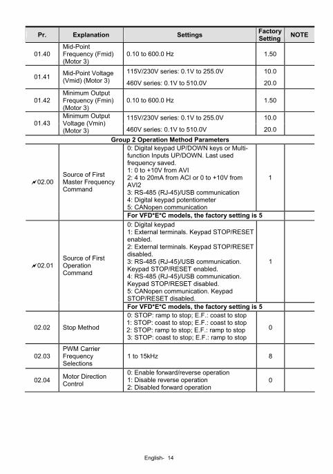
Pr. Explanation Settings Factory Setting NOTE
01.40 Mid-Point Frequency (Fmid) (Motor 3)
0.10 to 600.0 Hz 1.50
115V/230V series: 0.1V to 255.0V 10.0 01.41 Mid-Point Voltage
(Vmid) (Motor 3) 460V series: 0.1V to 510.0V 20.0
01.42 Minimum Output Frequency (Fmin) (Motor 3)
0.10 to 600.0 Hz 1.50
115V/230V series: 0.1V to 255.0V 10.0 01.43
Minimum Output Voltage (Vmin) (Motor 3) 460V series: 0.1V to 510.0V 20.0
Group 2 Operation Method Parameters 0: Digital keypad UP/DOWN keys or Multi-function Inputs UP/DOWN. Last used frequency saved. 1: 0 to +10V from AVI 2: 4 to 20mA from ACI or 0 to +10V from AVI2 3: RS-485 (RJ-45)/USB communication 4: Digital keypad potentiometer 5: CANopen communication
1
02.00 Source of First Master Frequency Command
For VFD*E*C models, the factory setting is 5 0: Digital keypad 1: External terminals. Keypad STOP/RESET enabled. 2: External terminals. Keypad STOP/RESET disabled. 3: RS-485 (RJ-45)/USB communication. Keypad STOP/RESET enabled. 4: RS-485 (RJ-45)/USB communication. Keypad STOP/RESET disabled. 5: CANopen communication. Keypad STOP/RESET disabled.
1
02.01 Source of First Operation Command
For VFD*E*C models, the factory setting is 5
02.02 Stop Method
0: STOP: ramp to stop; E.F.: coast to stop 1: STOP: coast to stop; E.F.: coast to stop 2: STOP: ramp to stop; E.F.: ramp to stop 3: STOP: coast to stop; E.F.: ramp to stop
0
02.03 PWM Carrier Frequency Selections
1 to 15kHz 8
02.04 Motor Direction Control
0: Enable forward/reverse operation 1: Disable reverse operation 2: Disabled forward operation
0
English- 15
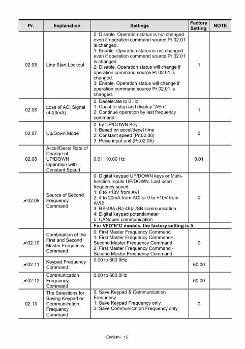
Pr. Explanation Settings Factory Setting NOTE
02.05 Line Start Lockout
0: Disable. Operation status is not changed even if operation command source Pr.02.01 is changed. 1: Enable. Operation status is not changed even if operation command source Pr.02.01 is changed. 2: Disable. Operation status will change if operation command source Pr.02.01 is changed. 3: Enable. Operation status will change if operation command source Pr.02.01 is changed.
1
02.06 Loss of ACI Signal (4-20mA)
0: Decelerate to 0 Hz 1: Coast to stop and display “AErr” 2: Continue operation by last frequency command
1
02.07 Up/Down Mode
0: by UP/DOWN Key 1: Based on accel/decel time 2: Constant speed (Pr.02.08) 3: Pulse input unit (Pr.02.08)
0
02.08
Accel/Decel Rate of Change of UP/DOWN Operation with Constant Speed
0.01~10.00 Hz 0.01
0: Digital keypad UP/DOWN keys or Multi-function Inputs UP/DOWN. Last used frequency saved. 1: 0 to +10V from AVI 2: 4 to 20mA from ACI or 0 to +10V from AVI2 3: RS-485 (RJ-45)/USB communication 4: Digital keypad potentiometer 5: CANopen communication
0
02.09 Source of Second Frequency Command
For VFD*E*C models, the factory setting is 5
02.10 Combination of the First and Second Master Frequency Command
0: First Master Frequency Command 1: First Master Frequency Command+ Second Master Frequency Command 2: First Master Frequency Command - Second Master Frequency Command
0
02.11 Keypad Frequency Command
0.00 to 600.0Hz 60.00
02.12 Communication Frequency Command
0.00 to 600.0Hz 60.00
02.13
The Selections for Saving Keypad or Communication Frequency Command
0: Save Keypad & Communication Frequency 1: Save Keypad Frequency only 2: Save Communication Frequency only
0
English- 16
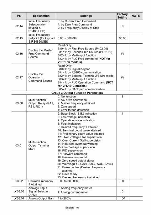
Pr. Explanation Settings Factory Setting NOTE
02.14
Initial Frequency Selection (for keypad & RS485/USB)
0: by Current Freq Command 1: by Zero Freq Command 2: by Frequency Display at Stop 0
02.15 Initial Frequency Setpoint (for keypad & RS485/USB)
0.00 ~ 600.0Hz 60.00
02.16 Display the Master Freq Command Source
Read Only Bit0=1: by First Freq Source (Pr.02.00) Bit1=1: by Second Freq Source (Pr.02.09) Bit2=1: by Multi-input function Bit3=1: by PLC Freq command (NOT for VFD*E*C models)
##
02.17 Display the Operation Command Source
Read Only Bit0=1: by Digital Keypad Bit1=1: by RS485 communication Bit2=1: by External Terminal 2/3 wire modeBit3=1: by Multi-input function Bit4=1: by PLC Operation Command (NOT for VFD*E*C models) Bit5=1: by CANopen communication
##
Group 3 Output Function Parameters
03.00 Multi-function Output Relay (RA1, RB1, RC1)
0: No function 1: AC drive operational 2: Master frequency attained 3: Zero speed 4: Over torque detection
8
03.01 Multi-function Output Terminal MO1
5: Base-Block (B.B.) indication 6: Low-voltage indication 7: Operation mode indication 8: Fault indication 9: Desired frequency 1 attained 10: Terminal count value attained 11: Preliminary count value attained 12: Over Voltage Stall supervision 13: Over Current Stall supervision 14: Heat sink overheat warning 15: Over Voltage supervision 16: PID supervision 17: Forward command 18: Reverse command 19: Zero speed output signal 20: Warning(FbE,Cexx, AoL2, AUE, SAvE)21: Brake control (Desired frequency
attained) 22: Drive ready 23: Desired frequency 2 attained
1
03.02 Desired Frequency 1 Attained
0.00 to 600.0Hz 0.00
03.03 Analog Output Signal Selection (AFM)
0: Analog frequency meter 1: Analog current meter 0
03.04 Analog Output Gain 1 to 200% 100
English- 17
Pr. Explanation Settings Factory Setting NOTE
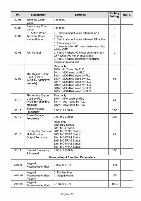
03.05 Terminal Count Value
0 to 9999 0
03.06 Preliminary Count Value 0 to 9999 0
03.07 EF Active When Terminal Count Value Attained
0: Terminal count value attained, no EF display 1: Terminal count value attained, EF active
0
03.08 Fan Control
0: Fan always ON 1: 1 minute after AC motor drive stops, fan will be OFF 2: Fan ON when AC motor drive runs, fan OFF when AC motor drive stops 3: Fan ON when preliminary heatsink temperature attained
0
03.09
The Digital Output Used by PLC (NOT for VFD*E*C models)
Read only Bit0=1:RLY used by PLC Bit1=1:MO1 used by PLC Bit2=1:MO2/RA2 used by PLC Bit3=1:MO3/RA3 used by PLC Bit4=1:MO4/RA4 used by PLC Bit5=1:MO5/RA5 used by PLC Bit6=1:MO6/RA6 used by PLC Bit7=1:MO7/RA7 used by PLC
##
03.10
The Analog Output Used by PLC (NOT for VFD*E*C models)
Read only Bit0=1:AFM used by PLC Bit1=1: AO1 used by PLC Bit2=1: AO2 used by PLC
##
03.11 Brake Release Frequency 0.00 to 20.00Hz 0.00
03.12 Brake Engage Frequency 0.00 to 20.00Hz 0.00
03.13 Display the Status of Multi-function Output Terminals
Read only Bit0: RLY Status Bit1: MO1 Status Bit2: MO2/RA2 Status Bit3: MO3/RA3 Status Bit4: MO4/RA4 Status Bit5: MO5/RA5 Status Bit6: MO6/RA6 Status Bit7: MO7/RA7 Status
##
03.14 Desired Frequency 2 Attained
0.00 to 600.0Hz 0.00
Group 4 Input Function Parameters
04.00 Keypad Potentiometer Bias 0.0 to 100.0 % 0.0
04.01
Keypad Potentiometer Bias Polarity
0: Positive bias 1: Negative bias 00
04.02 Keypad Potentiometer Gain 0.1 to 200.0 % 100.0
English- 18
Pr. Explanation Settings Factory Setting NOTE
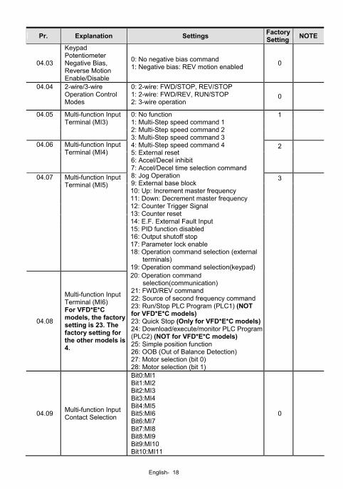
04.03
Keypad Potentiometer Negative Bias, Reverse Motion Enable/Disable
0: No negative bias command 1: Negative bias: REV motion enabled 0
04.04 2-wire/3-wire Operation Control Modes
0: 2-wire: FWD/STOP, REV/STOP 1: 2-wire: FWD/REV, RUN/STOP 2: 3-wire operation
0
1
04.05 Multi-function Input Terminal (MI3)
2
04.06 Multi-function Input Terminal (MI4)
3
04.07 Multi-function Input Terminal (MI5)
0: No function 1: Multi-Step speed command 1 2: Multi-Step speed command 2 3: Multi-Step speed command 3 4: Multi-Step speed command 4 5: External reset 6: Accel/Decel inhibit 7: Accel/Decel time selection command 8: Jog Operation 9: External base block 10: Up: Increment master frequency 11: Down: Decrement master frequency 12: Counter Trigger Signal 13: Counter reset 14: E.F. External Fault Input 15: PID function disabled 16: Output shutoff stop 17: Parameter lock enable 18: Operation command selection (external
terminals) 19: Operation command selection(keypad)
04.08
Multi-function Input Terminal (MI6) For VFD*E*C models, the factory setting is 23. The factory setting for the other models is 4.
20: Operation command selection(communication)
21: FWD/REV command 22: Source of second frequency command 23: Run/Stop PLC Program (PLC1) (NOT for VFD*E*C models) 23: Quick Stop (Only for VFD*E*C models)24: Download/execute/monitor PLC Program (PLC2) (NOT for VFD*E*C models) 25: Simple position function 26: OOB (Out of Balance Detection) 27: Motor selection (bit 0) 28: Motor selection (bit 1)
04.09 Multi-function Input Contact Selection
Bit0:MI1 Bit1:MI2 Bit2:MI3 Bit3:MI4 Bit4:MI5 Bit5:MI6 Bit6:MI7 Bit7:MI8 Bit8:MI9 Bit9:MI10 Bit10:MI11
0
English- 19
Pr. Explanation Settings Factory Setting NOTE
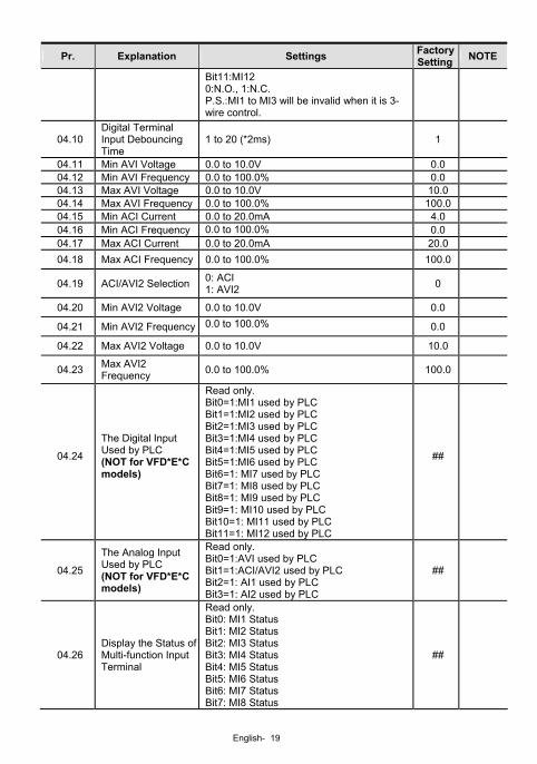
Bit11:MI12 0:N.O., 1:N.C. P.S.:MI1 to MI3 will be invalid when it is 3-wire control.
04.10 Digital Terminal Input Debouncing Time
1 to 20 (*2ms) 1
04.11 Min AVI Voltage 0.0 to 10.0V 0.0 04.12 Min AVI Frequency 0.0 to 100.0% 0.0 04.13 Max AVI Voltage 0.0 to 10.0V 10.0 04.14 Max AVI Frequency 0.0 to 100.0% 100.0 04.15 Min ACI Current 0.0 to 20.0mA 4.0 04.16 Min ACI Frequency 0.0 to 100.0% 0.0 04.17 Max ACI Current 0.0 to 20.0mA 20.0 04.18 Max ACI Frequency 0.0 to 100.0% 100.0
04.19 ACI/AVI2 Selection 0: ACI 1: AVI2 0
04.20 Min AVI2 Voltage 0.0 to 10.0V 0.0
04.21 Min AVI2 Frequency 0.0 to 100.0% 0.0
04.22 Max AVI2 Voltage 0.0 to 10.0V 10.0
04.23 Max AVI2 Frequency 0.0 to 100.0% 100.0
04.24
The Digital Input Used by PLC (NOT for VFD*E*C models)
Read only. Bit0=1:MI1 used by PLC Bit1=1:MI2 used by PLC Bit2=1:MI3 used by PLC Bit3=1:MI4 used by PLC Bit4=1:MI5 used by PLC Bit5=1:MI6 used by PLC Bit6=1: MI7 used by PLC Bit7=1: MI8 used by PLC Bit8=1: MI9 used by PLC Bit9=1: MI10 used by PLC Bit10=1: MI11 used by PLC Bit11=1: MI12 used by PLC
##
04.25
The Analog Input Used by PLC (NOT for VFD*E*C models)
Read only. Bit0=1:AVI used by PLC Bit1=1:ACI/AVI2 used by PLC Bit2=1: AI1 used by PLC Bit3=1: AI2 used by PLC
##
04.26 Display the Status of Multi-function Input Terminal
Read only. Bit0: MI1 Status Bit1: MI2 Status Bit2: MI3 Status Bit3: MI4 Status Bit4: MI5 Status Bit5: MI6 Status Bit6: MI7 Status Bit7: MI8 Status
##
English- 20
Pr. Explanation Settings Factory Setting NOTE
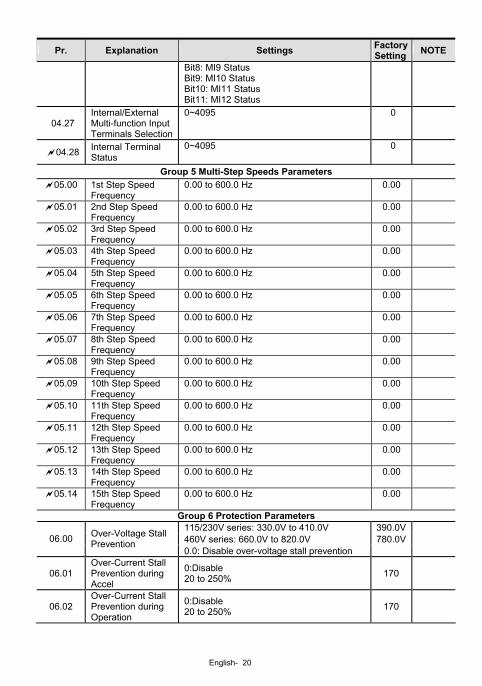
Bit8: MI9 Status Bit9: MI10 Status Bit10: MI11 Status Bit11: MI12 Status
04.27 Internal/External Multi-function Input Terminals Selection
0~4095 0
04.28 Internal Terminal Status
0~4095 0
Group 5 Multi-Step Speeds Parameters 05.00 1st Step Speed
Frequency 0.00 to 600.0 Hz 0.00
05.01 2nd Step Speed Frequency
0.00 to 600.0 Hz 0.00
05.02 3rd Step Speed Frequency
0.00 to 600.0 Hz 0.00
05.03 4th Step Speed Frequency
0.00 to 600.0 Hz 0.00
05.04 5th Step Speed Frequency
0.00 to 600.0 Hz 0.00
05.05 6th Step Speed Frequency
0.00 to 600.0 Hz 0.00
05.06 7th Step Speed Frequency
0.00 to 600.0 Hz 0.00
05.07 8th Step Speed Frequency
0.00 to 600.0 Hz 0.00
05.08 9th Step Speed Frequency
0.00 to 600.0 Hz 0.00
05.09 10th Step Speed Frequency
0.00 to 600.0 Hz 0.00
05.10 11th Step Speed Frequency
0.00 to 600.0 Hz 0.00
05.11 12th Step Speed Frequency
0.00 to 600.0 Hz 0.00
05.12 13th Step Speed Frequency
0.00 to 600.0 Hz 0.00
05.13 14th Step Speed Frequency
0.00 to 600.0 Hz 0.00
05.14 15th Step Speed Frequency
0.00 to 600.0 Hz 0.00
Group 6 Protection Parameters 115/230V series: 330.0V to 410.0V 390.0V460V series: 660.0V to 820.0V 780.0V06.00 Over-Voltage Stall
Prevention 0.0: Disable over-voltage stall prevention
06.01 Over-Current Stall Prevention during Accel
0:Disable 20 to 250% 170
06.02 Over-Current Stall Prevention during Operation
0:Disable 20 to 250% 170
English- 21
Pr. Explanation Settings Factory Setting NOTE
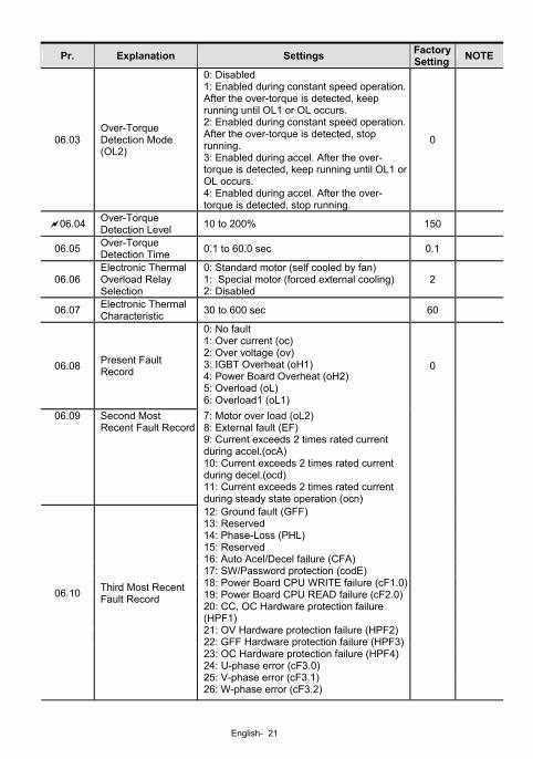
06.03 Over-Torque Detection Mode (OL2)
0: Disabled 1: Enabled during constant speed operation. After the over-torque is detected, keep running until OL1 or OL occurs. 2: Enabled during constant speed operation. After the over-torque is detected, stop running. 3: Enabled during accel. After the over-torque is detected, keep running until OL1 or OL occurs. 4: Enabled during accel. After the over-torque is detected, stop running.
0
06.04 Over-Torque Detection Level 10 to 200% 150
06.05 Over-Torque Detection Time 0.1 to 60.0 sec 0.1
06.06 Electronic Thermal Overload Relay Selection
0: Standard motor (self cooled by fan) 1: Special motor (forced external cooling) 2: Disabled
2
06.07 Electronic Thermal Characteristic 30 to 600 sec 60
06.08 Present Fault Record
0: No fault 1: Over current (oc) 2: Over voltage (ov) 3: IGBT Overheat (oH1) 4: Power Board Overheat (oH2) 5: Overload (oL) 6: Overload1 (oL1)
0
06.09 Second Most Recent Fault Record
7: Motor over load (oL2) 8: External fault (EF) 9: Current exceeds 2 times rated current during accel.(ocA) 10: Current exceeds 2 times rated current during decel.(ocd) 11: Current exceeds 2 times rated current during steady state operation (ocn)
06.10 Third Most Recent Fault Record
12: Ground fault (GFF) 13: Reserved 14: Phase-Loss (PHL) 15: Reserved 16: Auto Acel/Decel failure (CFA) 17: SW/Password protection (codE) 18: Power Board CPU WRITE failure (cF1.0)19: Power Board CPU READ failure (cF2.0)20: CC, OC Hardware protection failure (HPF1) 21: OV Hardware protection failure (HPF2)22: GFF Hardware protection failure (HPF3)23: OC Hardware protection failure (HPF4)24: U-phase error (cF3.0) 25: V-phase error (cF3.1) 26: W-phase error (cF3.2)
English- 22
Pr. Explanation Settings Factory Setting NOTE
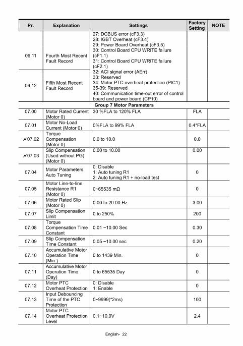
06.11 Fourth Most Recent
Fault Record
06.12 Fifth Most Recent Fault Record
27: DCBUS error (cF3.3) 28: IGBT Overheat (cF3.4) 29: Power Board Overheat (cF3.5) 30: Control Board CPU WRITE failure (cF1.1) 31: Control Board CPU WRITE failure (cF2.1) 32: ACI signal error (AErr) 33: Reserved 34: Motor PTC overheat protection (PtC1) 35-39: Reserved 40: Communication time-out error of control board and power board (CP10)
Group 7 Motor Parameters 07.00 Motor Rated Current
(Motor 0) 30 %FLA to 120% FLA FLA
07.01 Motor No-Load Current (Motor 0) 0%FLA to 99% FLA 0.4*FLA
07.02 Torque Compensation (Motor 0)
0.0 to 10.0 0.0
07.03 Slip Compensation (Used without PG) (Motor 0)
0.00 to 10.00 0.00
07.04 Motor Parameters Auto Tuning
0: Disable 1: Auto tuning R1 2: Auto tuning R1 + no-load test
0
07.05 Motor Line-to-line Resistance R1 (Motor 0)
0~65535 mΩ 0
07.06 Motor Rated Slip (Motor 0) 0.00 to 20.00 Hz 3.00
07.07 Slip Compensation Limit 0 to 250% 200
07.08 Torque Compensation Time Constant
0.01 ~10.00 Sec 0.30
07.09 Slip Compensation Time Constant 0.05 ~10.00 sec 0.20
07.10 Accumulative Motor Operation Time (Min.)
0 to 1439 Min. 0
07.11 Accumulative Motor Operation Time (Day)
0 to 65535 Day 0
07.12 Motor PTC Overheat Protection
0: Disable 1: Enable 0
07.13 Input Debouncing Time of the PTC Protection
0~9999(*2ms) 100
07.14 Motor PTC Overheat Protection Level
0.1~10.0V 2.4
English- 23
Pr. Explanation Settings Factory Setting NOTE
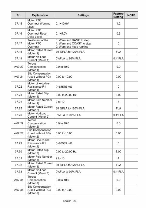
07.15 Motor PTC Overheat Warning Level
0.1~10.0V 1.2
07.16 Motor PTC Overheat Reset Delta Level
0.1~5.0V 0.6
07.17 Treatment of the Motor PTC Overheat
0: Warn and RAMP to stop 1: Warn and COAST to stop 2: Warn and keep running
0
07.18 Motor Rated Current(Motor 1) 30 %FLA to 120% FLA FLA
07.19 Motor No-Load Current (Motor 1) 0%FLA to 99% FLA 0.4*FLA
07.20 Torque Compensation (Motor 1)
0.0 to 10.0 0.0
07.21 Slip Compensation (Used without PG) (Motor 1)
0.00 to 10.00 0.00
07.22 Motor Line-to-line Resistance R1 (Motor 1)
0~65535 mΩ 0
07.23 Motor Rated Slip (Motor 1) 0.00 to 20.00 Hz 3.00
07.24 Motor Pole Number (Motor 1) 2 to 10 4
07.25 Motor Rated Current(Motor 2) 30 %FLA to 120% FLA FLA
07.26 Motor No-Load Current (Motor 2) 0%FLA to 99% FLA 0.4*FLA
07.27 Torque Compensation (Motor 2)
0.0 to 10.0 0.0
07.28 Slip Compensation (Used without PG) (Motor 2)
0.00 to 10.00 0.00
07.29 Motor Line-to-line Resistance R1 (Motor 2)
0~65535 mΩ 0
07.30 Motor Rated Slip (Motor 2) 0.00 to 20.00 Hz 3.00
07.31 Motor Pole Number (Motor 3) 2 to 10 4
07.32 Motor Rated Current(Motor 3) 30 %FLA to 120% FLA FLA
07.33 Motor No-Load Current (Motor 3) 0%FLA to 99% FLA 0.4*FLA
07.34 Torque Compensation (Motor 3)
0.0 to 10.0 0.0
07.35 Slip Compensation (Used without PG) (Motor 3)
0.00 to 10.00 0.00
English- 24
Pr. Explanation Settings Factory Setting NOTE
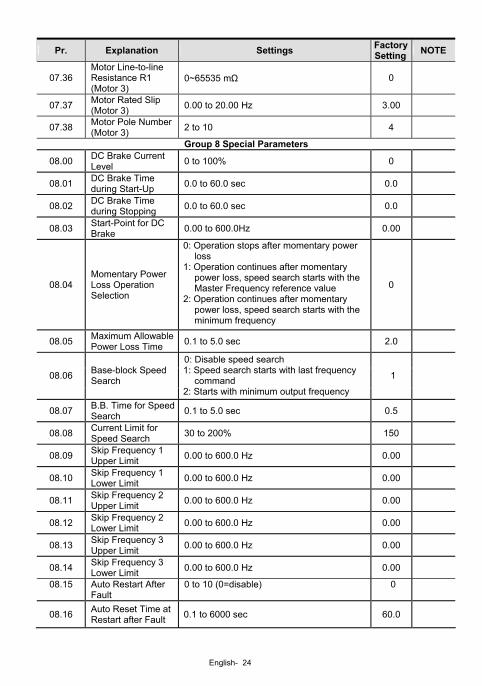
07.36 Motor Line-to-line Resistance R1 (Motor 3)
0~65535 mΩ 0
07.37 Motor Rated Slip (Motor 3) 0.00 to 20.00 Hz 3.00
07.38 Motor Pole Number (Motor 3) 2 to 10 4
Group 8 Special Parameters
08.00 DC Brake Current Level 0 to 100% 0
08.01 DC Brake Time during Start-Up 0.0 to 60.0 sec 0.0
08.02 DC Brake Time during Stopping 0.0 to 60.0 sec 0.0
08.03 Start-Point for DC Brake 0.00 to 600.0Hz 0.00
08.04 Momentary Power Loss Operation Selection
0: Operation stops after momentary power loss
1: Operation continues after momentary power loss, speed search starts with the Master Frequency reference value
2: Operation continues after momentary power loss, speed search starts with the minimum frequency
0
08.05 Maximum Allowable Power Loss Time 0.1 to 5.0 sec 2.0
08.06 Base-block Speed Search
0: Disable speed search 1: Speed search starts with last frequency
command 2: Starts with minimum output frequency
1
08.07 B.B. Time for Speed Search 0.1 to 5.0 sec 0.5
08.08 Current Limit for Speed Search 30 to 200% 150
08.09 Skip Frequency 1 Upper Limit 0.00 to 600.0 Hz 0.00
08.10 Skip Frequency 1 Lower Limit 0.00 to 600.0 Hz 0.00
08.11 Skip Frequency 2 Upper Limit 0.00 to 600.0 Hz 0.00
08.12 Skip Frequency 2 Lower Limit 0.00 to 600.0 Hz 0.00
08.13 Skip Frequency 3 Upper Limit 0.00 to 600.0 Hz 0.00
08.14 Skip Frequency 3 Lower Limit 0.00 to 600.0 Hz 0.00
08.15 Auto Restart After Fault
0 to 10 (0=disable) 0
08.16 Auto Reset Time at Restart after Fault 0.1 to 6000 sec 60.0
English- 25
Pr. Explanation Settings Factory Setting NOTE
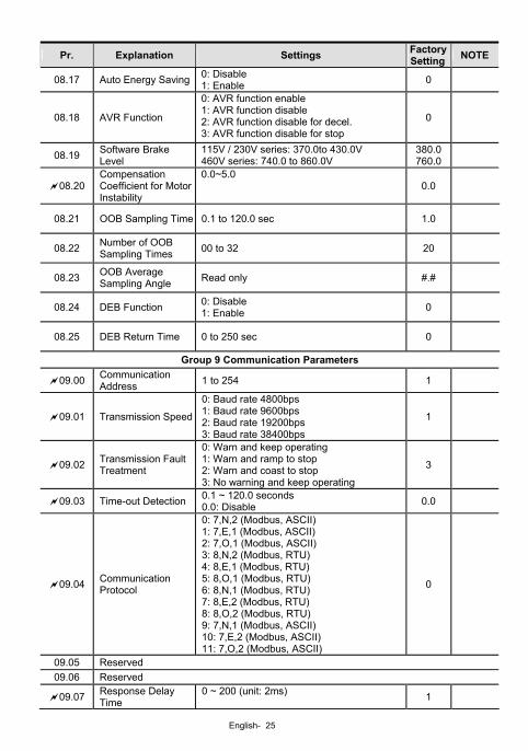
08.17 Auto Energy Saving 0: Disable 1: Enable 0
08.18 AVR Function
0: AVR function enable 1: AVR function disable 2: AVR function disable for decel. 3: AVR function disable for stop
0
08.19 Software Brake Level
115V / 230V series: 370.0to 430.0V 460V series: 740.0 to 860.0V
380.0760.0
08.20 Compensation Coefficient for Motor Instability
0.0~5.0 0.0
08.21 OOB Sampling Time 0.1 to 120.0 sec 1.0
08.22 Number of OOB Sampling Times 00 to 32 20
08.23 OOB Average Sampling Angle Read only #.#
08.24 DEB Function 0: Disable 1: Enable 0
08.25 DEB Return Time 0 to 250 sec 0
Group 9 Communication Parameters
09.00 Communication Address 1 to 254 1
09.01 Transmission Speed
0: Baud rate 4800bps 1: Baud rate 9600bps 2: Baud rate 19200bps 3: Baud rate 38400bps
1
09.02 Transmission Fault Treatment
0: Warn and keep operating 1: Warn and ramp to stop 2: Warn and coast to stop 3: No warning and keep operating
3
09.03 Time-out Detection 0.1 ~ 120.0 seconds 0.0: Disable 0.0
09.04 Communication Protocol
0: 7,N,2 (Modbus, ASCII) 1: 7,E,1 (Modbus, ASCII) 2: 7,O,1 (Modbus, ASCII) 3: 8,N,2 (Modbus, RTU) 4: 8,E,1 (Modbus, RTU) 5: 8,O,1 (Modbus, RTU) 6: 8,N,1 (Modbus, RTU) 7: 8,E,2 (Modbus, RTU) 8: 8,O,2 (Modbus, RTU) 9: 7,N,1 (Modbus, ASCII) 10: 7,E,2 (Modbus, ASCII) 11: 7,O,2 (Modbus, ASCII)
0
09.05 Reserved 09.06 Reserved
09.07 Response Delay Time
0 ~ 200 (unit: 2ms) 1
English- 26
Pr. Explanation Settings Factory Setting NOTE
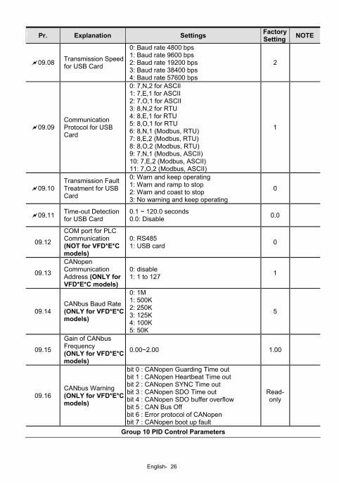
09.08 Transmission Speedfor USB Card
0: Baud rate 4800 bps 1: Baud rate 9600 bps 2: Baud rate 19200 bps 3: Baud rate 38400 bps 4: Baud rate 57600 bps
2
09.09 Communication Protocol for USB Card
0: 7,N,2 for ASCII 1: 7,E,1 for ASCII 2: 7,O,1 for ASCII 3: 8,N,2 for RTU 4: 8,E,1 for RTU 5: 8,O,1 for RTU 6: 8,N,1 (Modbus, RTU) 7: 8,E,2 (Modbus, RTU) 8: 8,O,2 (Modbus, RTU) 9: 7,N,1 (Modbus, ASCII) 10: 7,E,2 (Modbus, ASCII) 11: 7,O,2 (Modbus, ASCII)
1
09.10 Transmission Fault Treatment for USB Card
0: Warn and keep operating 1: Warn and ramp to stop 2: Warn and coast to stop 3: No warning and keep operating
0
09.11 Time-out Detection for USB Card
0.1 ~ 120.0 seconds 0.0: Disable 0.0
09.12
COM port for PLC Communication (NOT for VFD*E*C models)
0: RS485 1: USB card 0
09.13
CANopen Communication Address (ONLY for VFD*E*C models)
0: disable 1: 1 to 127 1
09.14 CANbus Baud Rate (ONLY for VFD*E*C models)
0: 1M 1: 500K 2: 250K 3: 125K 4: 100K 5: 50K
5
09.15
Gain of CANbus Frequency (ONLY for VFD*E*C models)
0.00~2.00 1.00
09.16 CANbus Warning (ONLY for VFD*E*C models)
bit 0 : CANopen Guarding Time out bit 1 : CANopen Heartbeat Time out bit 2 : CANopen SYNC Time out bit 3 : CANopen SDO Time out bit 4 : CANopen SDO buffer overflow bit 5 : CAN Bus Off bit 6 : Error protocol of CANopen bit 7 : CANopen boot up fault
Read-only
Group 10 PID Control Parameters
English- 27
Pr. Explanation Settings Factory Setting NOTE
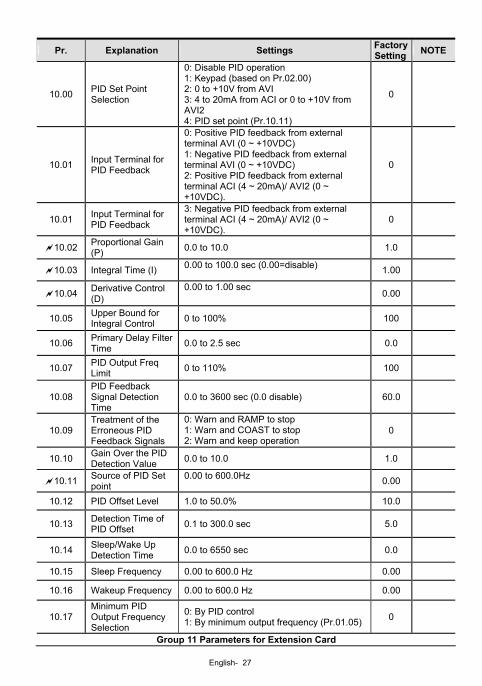
10.00 PID Set Point Selection
0: Disable PID operation 1: Keypad (based on Pr.02.00) 2: 0 to +10V from AVI 3: 4 to 20mA from ACI or 0 to +10V from AVI2 4: PID set point (Pr.10.11)
0
10.01 Input Terminal for PID Feedback
0: Positive PID feedback from external terminal AVI (0 ~ +10VDC) 1: Negative PID feedback from external terminal AVI (0 ~ +10VDC) 2: Positive PID feedback from external terminal ACI (4 ~ 20mA)/ AVI2 (0 ~ +10VDC).
0
10.01 Input Terminal for PID Feedback
3: Negative PID feedback from external terminal ACI (4 ~ 20mA)/ AVI2 (0 ~ +10VDC).
0
10.02 Proportional Gain (P) 0.0 to 10.0 1.0
10.03 Integral Time (I) 0.00 to 100.0 sec (0.00=disable) 1.00
10.04 Derivative Control (D)
0.00 to 1.00 sec 0.00
10.05 Upper Bound for Integral Control 0 to 100% 100
10.06 Primary Delay Filter Time 0.0 to 2.5 sec 0.0
10.07 PID Output Freq Limit 0 to 110% 100
10.08 PID Feedback Signal Detection Time
0.0 to 3600 sec (0.0 disable) 60.0
10.09 Treatment of the Erroneous PID Feedback Signals
0: Warn and RAMP to stop 1: Warn and COAST to stop 2: Warn and keep operation
0
10.10 Gain Over the PID Detection Value 0.0 to 10.0 1.0
10.11 Source of PID Set point
0.00 to 600.0Hz 0.00
10.12 PID Offset Level 1.0 to 50.0% 10.0
10.13 Detection Time of PID Offset 0.1 to 300.0 sec 5.0
10.14 Sleep/Wake Up Detection Time 0.0 to 6550 sec 0.0
10.15 Sleep Frequency 0.00 to 600.0 Hz 0.00
10.16 Wakeup Frequency 0.00 to 600.0 Hz 0.00
10.17 Minimum PID Output Frequency Selection
0: By PID control 1: By minimum output frequency (Pr.01.05) 0
Group 11 Parameters for Extension Card
English- 28
Pr. Explanation Settings Factory Setting NOTE
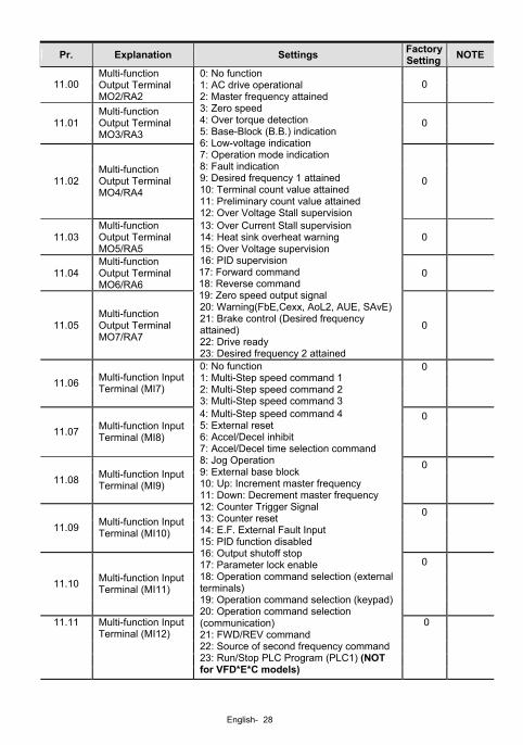
11.00 Multi-function Output Terminal MO2/RA2
0
11.01 Multi-function Output Terminal MO3/RA3
0
11.02 Multi-function Output Terminal MO4/RA4
0: No function 1: AC drive operational 2: Master frequency attained 3: Zero speed 4: Over torque detection 5: Base-Block (B.B.) indication 6: Low-voltage indication 7: Operation mode indication 8: Fault indication 9: Desired frequency 1 attained 10: Terminal count value attained 11: Preliminary count value attained 12: Over Voltage Stall supervision
0
11.03 Multi-function Output Terminal MO5/RA5
0
11.04 Multi-function Output Terminal MO6/RA6
0
11.05 Multi-function Output Terminal MO7/RA7
13: Over Current Stall supervision 14: Heat sink overheat warning 15: Over Voltage supervision 16: PID supervision 17: Forward command 18: Reverse command 19: Zero speed output signal 20: Warning(FbE,Cexx, AoL2, AUE, SAvE)21: Brake control (Desired frequency attained) 22: Drive ready 23: Desired frequency 2 attained
0
0 11.06 Multi-function Input
Terminal (MI7)
0: No function 1: Multi-Step speed command 1 2: Multi-Step speed command 2 3: Multi-Step speed command 3
0
11.07 Multi-function Input Terminal (MI8)
0 11.08 Multi-function Input
Terminal (MI9)
0
11.09 Multi-function Input Terminal (MI10)
0
11.10 Multi-function Input
Terminal (MI11)
0
11.11 Multi-function Input Terminal (MI12)
4: Multi-Step speed command 4 5: External reset 6: Accel/Decel inhibit 7: Accel/Decel time selection command 8: Jog Operation 9: External base block 10: Up: Increment master frequency 11: Down: Decrement master frequency 12: Counter Trigger Signal 13: Counter reset 14: E.F. External Fault Input 15: PID function disabled 16: Output shutoff stop 17: Parameter lock enable 18: Operation command selection (external terminals) 19: Operation command selection (keypad)20: Operation command selection (communication) 21: FWD/REV command 22: Source of second frequency command 23: Run/Stop PLC Program (PLC1) (NOT for VFD*E*C models)
English- 29
Pr. Explanation Settings Factory Setting NOTE
23: Quick Stop (Only for VFD*E*C models)24: Download/execute/monitor PLC Program (PLC2) (NOT for VFD*E*C models) 25: Simple position function 26: OOB (Out of Balance Detection) 27: Motor selection (bit 0) 28: Motor selection (bit 1)
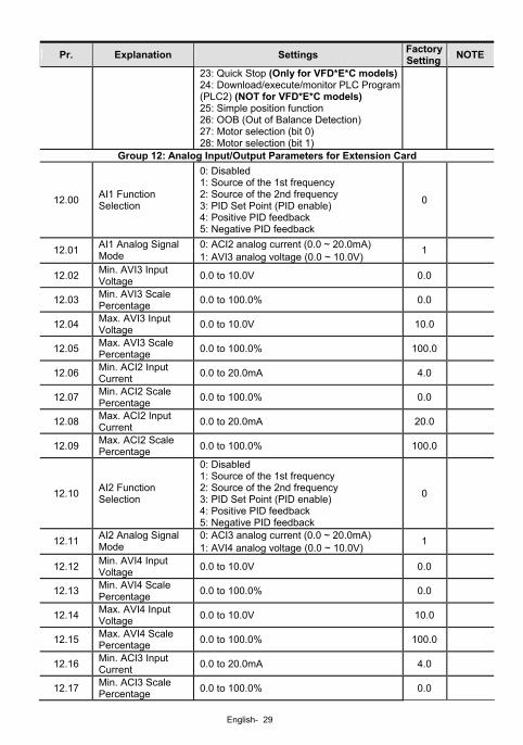
Group 12: Analog Input/Output Parameters for Extension Card
12.00 AI1 Function Selection
0: Disabled 1: Source of the 1st frequency 2: Source of the 2nd frequency 3: PID Set Point (PID enable) 4: Positive PID feedback 5: Negative PID feedback
0
0: ACI2 analog current (0.0 ~ 20.0mA) 12.01 AI1 Analog Signal Mode 1: AVI3 analog voltage (0.0 ~ 10.0V)
1
12.02 Min. AVI3 Input Voltage 0.0 to 10.0V 0.0
12.03 Min. AVI3 Scale Percentage 0.0 to 100.0% 0.0
12.04 Max. AVI3 Input Voltage 0.0 to 10.0V 10.0
12.05 Max. AVI3 Scale Percentage 0.0 to 100.0% 100.0
12.06 Min. ACI2 Input Current 0.0 to 20.0mA 4.0
12.07 Min. ACI2 Scale Percentage 0.0 to 100.0% 0.0
12.08 Max. ACI2 Input Current 0.0 to 20.0mA 20.0
12.09 Max. ACI2 Scale Percentage 0.0 to 100.0% 100.0
12.10 AI2 Function Selection
0: Disabled 1: Source of the 1st frequency 2: Source of the 2nd frequency 3: PID Set Point (PID enable) 4: Positive PID feedback 5: Negative PID feedback
0
0: ACI3 analog current (0.0 ~ 20.0mA) 12.11 AI2 Analog Signal Mode 1: AVI4 analog voltage (0.0 ~ 10.0V)
1
12.12 Min. AVI4 Input Voltage 0.0 to 10.0V 0.0
12.13 Min. AVI4 Scale Percentage 0.0 to 100.0% 0.0
12.14 Max. AVI4 Input Voltage 0.0 to 10.0V 10.0
12.15 Max. AVI4 Scale Percentage 0.0 to 100.0% 100.0
12.16 Min. ACI3 Input Current 0.0 to 20.0mA 4.0
12.17 Min. ACI3 Scale Percentage 0.0 to 100.0% 0.0
English- 30
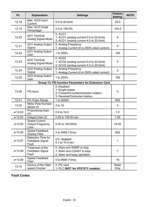
Pr. Explanation Settings Factory Setting NOTE
12.18 Max. ACI3 Input Current 0.0 to 20.0mA 20.0
12.19 Max. ACI3 Scale Percentage 0.0 to 100.0% 100.0
12.20 AO1 Terminal Analog Signal Mode
0: AVO1 1: ACO1 (analog current 0.0 to 20.0mA) 2: ACO1 (analog current 4.0 to 20.0mA)
0
0: Analog Frequency 12.21 AO1 Analog Output Signal 1: Analog Current (0 to 250% rated current)
0
12.22 AO1 Analog Output Gain 1 to 200% 100
0: AVO2 1: ACO2 (analog current 0.0 to 20.0mA) 12.23 AO2 Terminal
Analog Signal Mode2: ACO2 (analog current 4.0 to 20.0mA)
0
0: Analog Frequency 12.24 AO2 Analog Output Signal 1: Analog Current (0 to 250% rated current)
0
12.25 AO2 Analog Output Gain 1 to 200% 100
Group 13: PG function Parameters for Extension Card
13.00 PG Input
0: Disabled 1: Single phase 2: Forward/Counterclockwise rotation 3: Reverse/Clockwise rotation
0
13.01 PG Pulse Range 1 to 20000 600
13.02 Motor Pole Number (Motor 0) 2 to 10 4
13.03 Proportional Gain (P) 0.0 to 10.0 1.0
13.04 Integral Gain (I) 0.00 to 100.00 sec 1.00
13.05 Speed Control Output Frequency Limit
0.00 to 100.00Hz 10.00
13.06 Speed Feedback Display Filter 0 to 9999 (*2ms) 500
13.07 Detection Time for Feedback Signal Fault
0.0: disabled 0.1 to 10.0 sec 1
0: Warn and RAMP to stop 1: Warn and COAST to stop 13.08
Treatment of the Feedback Signal Fault 2: Warn and keep operation
1
13.09 Speed Feedback Filter 0 to 9999 (*2ms) 16
0: PG card 13.10 Source of the High-speed Counter 1: PLC (NOT for VFD*E*C models)
Read Only
Fault Codes
English- 31
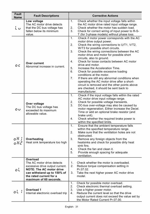
Fault Name Fault Descriptions Corrective Actions
Low voltage The AC motor drive detects that the DC bus voltage has fallen below its minimum value.
1. Check whether the input voltage falls within the AC motor drive rated input voltage range.
2. Check whether the motor has sudden load. 3. Check for correct wiring of input power to R-S-
T (for 3-phase models) without phase loss.
Over current Abnormal increase in current.
1. Check if motor power corresponds with the AC motor drive output power.
2. Check the wiring connections to U/T1, V/T2, W/T3 for possible short circuits.
3. Check the wiring connections between the AC motor drive and motor for possible short circuits, also to ground.
4. Check for loose contacts between AC motor drive and motor.
5. Increase the Acceleration Time. 6. Check for possible excessive loading
conditions at the motor. 7. If there are still any abnormal conditions when
operating the AC motor drive after a short-circuit is removed and the other points above are checked, it should be sent back to manufacturer.
Over voltage The DC bus voltage has exceeded its maximum allowable value.
1. Check if the input voltage falls within the rated AC motor drive input voltage range.
2. Check for possible voltage transients. 3. DC-bus over-voltage may also be caused by
motor regeneration. Either increase the Decel. Time or add an optional brake resistor (and brake unit).
4. Check whether the required brake power is within the specified limits.
Overheating Heat sink temperature too high
1. Ensure that the ambient temperature falls within the specified temperature range.
2. Make sure that the ventilation holes are not obstructed.
3. Remove any foreign objects from the heatsinks and check for possible dirty heat sink fins.
4. Check the fan and clean it. 5. Provide enough spacing for adequate
ventilation.
Overload The AC motor drive detects excessive drive output current.NOTE: The AC motor drive can withstand up to 150% of the rated current for a maximum of 60 seconds.
1. Check whether the motor is overloaded. 2. Reduce torque compensation setting in
Pr.07.02. 3. Take the next higher power AC motor drive
model.
Overload 1 Internal electronic overload trip
1. Check for possible motor overload. 2. Check electronic thermal overload setting. 3. Use a higher power motor. 4. Reduce the current level so that the drive
output current does not exceed the value set by the Motor Rated Current Pr.07.00.
English- 32
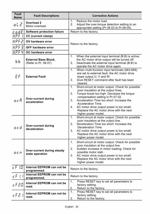
Fault Name Fault Descriptions Corrective Actions
Overload 2 Motor overload.
1. Reduce the motor load. 2. Adjust the over-torque detection setting to an
appropriate setting (Pr.06.03 to Pr.06.05). Software protection failure Return to the factory.
CC (current clamp)
OV hardware error
GFF hardware error
OC hardware error
Return to the factory.
External Base Block. (Refer to Pr. 08.07)
1. When the external input terminal (B.B) is active, the AC motor drive output will be turned off.
2. Deactivate the external input terminal (B.B) to operate the AC motor drive again.
External Fault
1. When multi-function input terminals (MI3-MI9) are set to external fault, the AC motor drive stops output U, V and W.
2. Give RESET command after fault has been cleared.
Over-current during acceleration
1. Short-circuit at motor output: Check for possible poor insulation at the output lines.
2. Torque boost too high: Decrease the torque compensation setting in Pr.07.02.
3. Acceleration Time too short: Increase the Acceleration Time.
4. AC motor drive output power is too small: Replace the AC motor drive with the next higher power model.
Over-current during deceleration
1. Short-circuit at motor output: Check for possible poor insulation at the output line.
2. Deceleration Time too short: Increase the Deceleration Time.
3. AC motor drive output power is too small: Replace the AC motor drive with the next higher power model.
Over-current during steady state operation
1. Short-circuit at motor output: Check for possible poor insulation at the output line.
2. Sudden increase in motor loading: Check for possible motor stall.
3. AC motor drive output power is too small: Replace the AC motor drive with the next higher power model.
Internal EEPROM can not be programmed. Return to the factory.
Internal EEPROM can not be programmed. Return to the factory.
Internal EEPROM can not be read.
1. Press RESET key to set all parameters to factory setting.
2. Return to the factory.
Internal EEPROM can not be read.
1. Press RESET key to set all parameters to factory setting.
2. Return to the factory.
English- 33
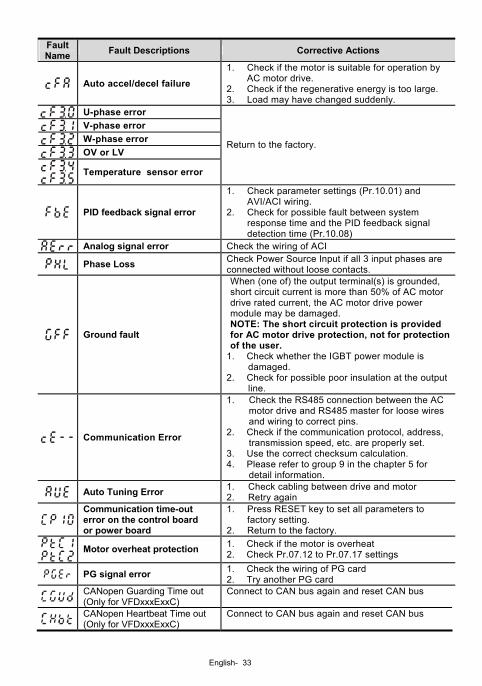
Fault Name Fault Descriptions Corrective Actions
Auto accel/decel failure 1. Check if the motor is suitable for operation by
AC motor drive. 2. Check if the regenerative energy is too large. 3. Load may have changed suddenly.
U-phase error V-phase error W-phase error OV or LV
Temperature sensor error
Return to the factory.
PID feedback signal error
1. Check parameter settings (Pr.10.01) and AVI/ACI wiring.
2. Check for possible fault between system response time and the PID feedback signal detection time (Pr.10.08)
Analog signal error Check the wiring of ACI
Phase Loss Check Power Source Input if all 3 input phases are connected without loose contacts.
Ground fault
When (one of) the output terminal(s) is grounded, short circuit current is more than 50% of AC motor drive rated current, the AC motor drive power module may be damaged. NOTE: The short circuit protection is provided for AC motor drive protection, not for protection of the user.
1. Check whether the IGBT power module is damaged.
2. Check for possible poor insulation at the output line.
Communication Error
1. Check the RS485 connection between the AC motor drive and RS485 master for loose wires and wiring to correct pins.
2. Check if the communication protocol, address, transmission speed, etc. are properly set.
3. Use the correct checksum calculation. 4. Please refer to group 9 in the chapter 5 for
detail information.
Auto Tuning Error 1. Check cabling between drive and motor 2. Retry again
Communication time-out error on the control board or power board
1. Press RESET key to set all parameters to factory setting.
2. Return to the factory. Motor overheat protection 1. Check if the motor is overheat
2. Check Pr.07.12 to Pr.07.17 settings
PG signal error 1. Check the wiring of PG card 2. Try another PG card
CANopen Guarding Time out (Only for VFDxxxExxC)
Connect to CAN bus again and reset CAN bus
CANopen Heartbeat Time out (Only for VFDxxxExxC)
Connect to CAN bus again and reset CAN bus
English- 34
Fault Name Fault Descriptions Corrective Actions
CANopen SYNC Time out (Only for VFDxxxExxC)
Check if CANopen synchronous message is abnormal
CANopen SDO Time out (Only for VFDxxxExxC)
Check if command channels are full
CANopen SDO buffer overflow (Only for VFDxxxExxC)
1. Too short time between commands, please check SDO message sent from the master
2. Reset CAN bus
CAN bus off (Only for VFDxxxExxC)
1. Check if it connects to terminal resistor 2. Check if the signal is abnormal 3. Check if the master is connected
CAN Boot up fault (Only for VFDxxxExxC)
1. Check if the master is connected 2. Reset CAN bus
Error communication protocol of CANopen (Only for VFDxxxExxC)
Check if the communication protocol is correct
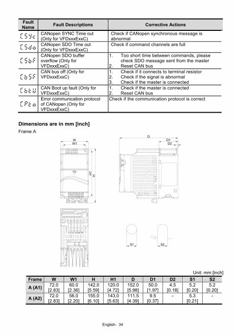
Dimensions are in mm [inch] Frame A
D
H1
H
WW1
S2S1
D1D2
Unit: mm [inch]
Frame W W1 H H1 D D1 D2 S1 S2
A (A1) 72.0 [2.83]
60.0 [2.36]
142.0[5.59]
120.0[4.72]
152.0[5.98]
50.0 [1.97]
4.5 [0.18]
5.2 [0.20]
5.2 [0.20]
A (A2) 72.0 [2.83]
56.0 [2.20]
155.0[6.10]
143.0[5.63]
111.5[4.39]
9.5 [0.37]
- 5.3 [0.21]
-
English- 35
NOTE
Frame A (A1): VFD002E11A/21A/23A, VFD004E11A/21A/23A/43A, VFD007E21A/23A/43A,
VFD015E23A/43A, VFD002E11C/21C/23C, VFD004E11C/21C/23C/43C, VFD007E21C/23C/43C,
VFD015E23C/43C, VFD002E11T/21T/23T, VFD004E11T/21T/23T/43T, VFD007E21T/23T/43T,
VFD015E23T/43T
Frame A (A2): VFD002E11P/21P/23P, VFD004E11P/21P/23P/43P, VFD007E21P/23P/43P,
VFD015E23P/43P
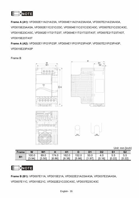
Frame B
DH
S2
H1
WW1
D1D2
S1
Unit: mm [inch]
Frame W W1 H H1 D D1 D2 S1 S2
B1 100.0 [3.94]
89.0 [3.50]
174.0[6.86]
162.0[6.38]
152.0[5.98]
50.0 [1.97]
4.0 [0.16]
5.5 [0.22]
5.5 [0.22]
NOTE
Frame B (B1): VFD007E11A, VFD015E21A, VFD022E21A/23A/43A, VFD037E23A/43A,
VFD007E11C, VFD015E21C, VFD022E21C/23C/43C, VFD037E23C/43C
English- 36
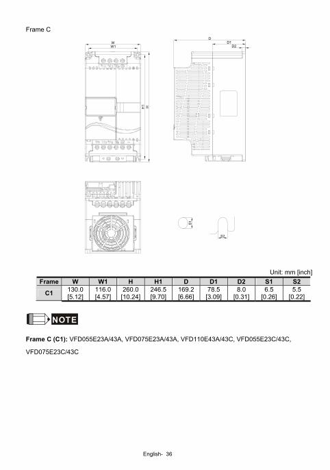
Frame C
HH1
W1W
S1
S2
DD1
D2
Unit: mm [inch] Frame W W1 H H1 D D1 D2 S1 S2
C1 130.0 [5.12]
116.0 [4.57]
260.0[10.24]
246.5[9.70]
169.2[6.66]
78.5 [3.09]
8.0 [0.31]
6.5 [0.26]
5.5 [0.22]
NOTE
Frame C (C1): VFD055E23A/43A, VFD075E23A/43A, VFD110E43A/43C, VFD055E23C/43C,
VFD075E23C/43C