Embed Size (px)
Citation preview
� CM 1243- �5
___________________
___________________
___________________
___________________
___________________
___________________
___________________
___________________
___________________
___________________
___________________
SIMATIC NET
CM 1243-5
Operating Instructions
04/2011 C79000-G8976-C246-01
Preface
Application and properties 1
Displays and connectors 2
Installing, connecting up and commissioning
3
Configuration and programming
4
Operating the module 5
Technical specifications 6
Dimension drawings A
Approvals B
References C
Training, Service & Support D
Legal information
Legal information Warning notice system
This manual contains notices you have to observe in order to ensure your personal safety, as well as to prevent damage to property. The notices referring to your personal safety are highlighted in the manual by a safety alert symbol, notices referring only to property damage have no safety alert symbol. These notices shown below are graded according to the degree of danger.
DANGER indicates that death or severe personal injury will result if proper precautions are not taken.
WARNING indicates that death or severe personal injury may result if proper precautions are not taken.
CAUTION with a safety alert symbol, indicates that minor personal injury can result if proper precautions are not taken.
CAUTION without a safety alert symbol, indicates that property damage can result if proper precautions are not taken.
NOTICE indicates that an unintended result or situation can occur if the corresponding information is not taken into account.
If more than one degree of danger is present, the warning notice representing the highest degree of danger will be used. A notice warning of injury to persons with a safety alert symbol may also include a warning relating to property damage.
Qualified Personnel The product/system described in this documentation may be operated only by personnel qualified for the specific task in accordance with the relevant documentation for the specific task, in particular its warning notices and safety instructions. Qualified personnel are those who, based on their training and experience, are capable of identifying risks and avoiding potential hazards when working with these products/systems.
Proper use of Siemens products Note the following:
WARNING Siemens products may only be used for the applications described in the catalog and in the relevant technical documentation. If products and components from other manufacturers are used, these must be recommended or approved by Siemens. Proper transport, storage, installation, assembly, commissioning, operation and maintenance are required to ensure that the products operate safely and without any problems. The permissible ambient conditions must be adhered to. The information in the relevant documentation must be observed.
Trademarks All names identified by ® are registered trademarks of the Siemens AG. The remaining trademarks in this publication may be trademarks whose use by third parties for their own purposes could violate the rights of the owner.
Disclaimer of Liability We have reviewed the contents of this publication to ensure consistency with the hardware and software described. Since variance cannot be precluded entirely, we cannot guarantee full consistency. However, the information in this publication is reviewed regularly and any necessary corrections are included in subsequent editions.
Siemens AG Industry Sector Postfach 48 48 90026 NÜRNBERG GERMANY
order number: C79000-G8976-C246 Ⓟ 04/2011
Copyright © Siemens AG 2011. Technical data subject to change
CM 1243-5 Operating Instructions, 04/2011, C79000-G8976-C246-01 3
Preface
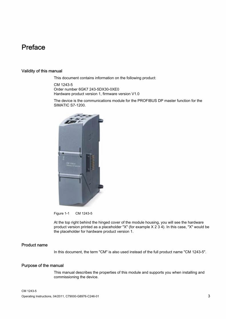
Validity of this manual This document contains information on the following product:
CM 1243-5 Order number 6GK7 243-5DX30-0XE0 Hardware product version 1, firmware version V1.0
The device is the communications module for the PROFIBUS DP master function for the SIMATIC S7-1200.
Figure 1-1 CM 1243-5
At the top right behind the hinged cover of the module housing, you will see the hardware product version printed as a placeholder "X" (for example X 2 3 4). In this case, "X" would be the placeholder for hardware product version 1.
Product name In this document, the term "CM" is also used instead of the full product name "CM 1243-5".
Purpose of the manual This manual describes the properties of this module and supports you when installing and commissioning the device.
Preface
CM 1243-5 4 Operating Instructions, 04/2011, C79000-G8976-C246-01
The necessary configuration steps are described in the form of an overview.
You will also find instructions for operation and maintenance and information on the diagnostics options of the device.
Required experience To install, commission and operate the CM, you require experience in the following areas:
● Automation engineering
● Setting up the SIMATIC S7-1200
● SIMATIC STEP 7
● Data transfer with PROFIBUS
Further information You will find an overview of further reading and references in the Appendix of this manual.
You will also find information about training, Service & Support and who to contact in the Appendix of this manual.
License conditions
NOTICE Open source software
Read the license conditions for open source software carefully before using the product. The acceptance of the disclaimers of liability and warranty it contains is a clear precondition of the use of open source software.
You will find the license conditions on the data medium with the product documentation.
CM 1243-5 Operating Instructions, 04/2011, C79000-G8976-C246-01 5
Table of contents
Preface ...................................................................................................................................................... 3
1 Application and properties ......................................................................................................................... 7
1.1 Connecting the S7-1200 to PROFIBUS.........................................................................................7
1.2 Communications services of the CM .............................................................................................7
1.3 Performance data ..........................................................................................................................8
1.4 Requirements for operation ...........................................................................................................9
1.5 Configuration examples for PROFIBUS ......................................................................................10
2 Displays and connectors.......................................................................................................................... 11
2.1 Opening the covers of the housing ..............................................................................................11
2.2 LEDs ............................................................................................................................................12
2.3 Electrical connections ..................................................................................................................15
3 Installing, connecting up and commissioning........................................................................................... 17
3.1 Warning overvoltage protection ...................................................................................................19
3.2 Installing and commissioning the CM 1243-5 ..............................................................................19
3.3 Pin assignment of the socket for the external power supply .......................................................22
3.4 Pinout of the D-sub socket...........................................................................................................23
4 Configuration and programming .............................................................................................................. 25
4.1 Configuration................................................................................................................................25
4.2 Programming................................................................................................................................26
5 Operating the module .............................................................................................................................. 27
5.1 Note on operation ........................................................................................................................27
5.2 Diagnostics...................................................................................................................................27
5.3 Downloading firmware .................................................................................................................28
5.4 Module replacement ....................................................................................................................28
6 Technical specifications........................................................................................................................... 29
A Dimension drawings ................................................................................................................................ 31
B Approvals................................................................................................................................................. 33
C References .............................................................................................................................................. 39
D Training, Service & Support ..................................................................................................................... 41
Glossary .................................................................................................................................................. 43
Index........................................................................................................................................................ 47

Table of contents
CM 1243-5 6 Operating Instructions, 04/2011, C79000-G8976-C246-01
CM 1243-5 Operating Instructions, 04/2011, C79000-G8976-C246-01 7
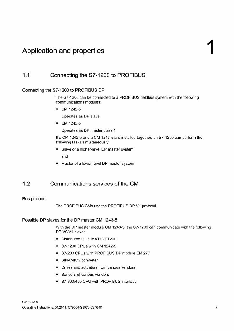
Application and properties 11.1 Connecting the S7-1200 to PROFIBUS
Connecting the S7-1200 to PROFIBUS DP The S7-1200 can be connected to a PROFIBUS fieldbus system with the following communications modules:
● CM 1242-5
Operates as DP slave
● CM 1243-5
Operates as DP master class 1
If a CM 1242-5 and a CM 1243-5 are installed together, an S7-1200 can perform the following tasks simultaneously:
● Slave of a higher-level DP master system
and
● Master of a lower-level DP master system
1.2 Communications services of the CM
Bus protocol The PROFIBUS CMs use the PROFIBUS DP-V1 protocol.
Possible DP slaves for the DP master CM 1243-5 With the DP master module CM 1243-5, the S7-1200 can communicate with the following DP-V0/V1 slaves:
● Distributed I/O SIMATIC ET200
● S7-1200 CPUs with CM 1242-5
● S7-200 CPUs with PROFIBUS DP module EM 277
● SINAMICS converter
● Drives and actuators from various vendors
● Sensors of various vendors
● S7-300/400 CPU with PROFIBUS interface
Application and properties 1.3 Performance data
CM 1243-5 8 Operating Instructions, 04/2011, C79000-G8976-C246-01
● S7-300/400 with PROFIBUS CP (for example CP 342-5)
● SIMATIC PC stations with PROFIBUS CP
Types of communication with the CM 1243-5 in DP-V1 The following types of communication are available with DP-V1:
● Cyclic communication
The CM supports cyclic communication for the transfer of process data between DP slave and DP master.
Cyclic communication is handled by the operating system of the CPU. No instructions or software blocks are required for this. The I/O data is read or written directly from/to the process image of the CPU.
● Acyclic communication
The CM also supports acyclic communication:
– The "RALRM" instruction is available for receiving interrupts of the DP slaves.
– The "RDREC" and "WRREC" instructions are available for transferring configuration, diagnostics or I/O data.
The SYNC/FREEZE and Get_Master_Diag functions are not supported.
Other communications services of the CM 1243-5 The CM 1243-5 supports the following additional communications services:
● S7 communication
– PUT/GET services
The DP master functions as a client and server for queries from other S7 controllers or PCs via PROFIBUS.
– PG/OP communication
The PG functions allow the downloading of configuration data and user programs from a PG and the transfer of diagnostics data to a PG.
Possible communications partners for OP communication are HMI panels, SIMATIC panel PCs with WinCC flexible or SCADA systems that support S7 communication.
1.3 Performance data
Transmission speeds of the CM 1243-5 As the transmission speed on PROFIBUS, values of 9.6 kbps to 12 Mbps are permitted for the CM.

Application and properties 1.4 Requirements for operation
CM 1243-5 Operating Instructions, 04/2011, C79000-G8976-C246-01 9
Characteristic data of the DP interface of the CM 1243-5 ● Number of DP slaves operable with a DP master: Maximum 16 *)
● Total number of operable slots: Maximum 256
Any distribution of the slots as I slots and Q slots is permitted.
● Size of the DP data areas of the DP master: Max. 1024 bytes
– Input area of the DP master in total: Max. 512 bytes
– Output area of the DP master in total: Max. 512 bytes
● Maximum size of the DP data areas of the DP slaves
– Input area per DP slave: Max. 244 bytes
– Output area per DP slave: Max. 244 bytes
– Diagnostics data area per DP slave: Max. 244 bytes
NOTICE
*) Maximum 16 DP slaves per station
For the constellation STEP 7 V11.0 and CPU firmware V2.0, resources are available for a maximum 16 DP slaves in total per station.
If you plug in a master module (CM 1243-5) and 1 or 2 slave modules (CM 1242-5) in a station at the same time, the maximum number of slaves that can be operated with the CM 1243-5 reduces by the CM 1242-5 modules plugged into the same station. The number of DP slaves that can be operated with the DP master is therefore reduced to 15 or 14.
Characteristic data of S7 communication ● Number of possible connections for S7 communication in total: 8
Of which maximum:
– Configured connections for PUT/GET services: 4
– PG connections: 1
– OP connections: 3
● User data per frame
– PUT: Max. 209 bytes
– GET: Max. 222 bytes
1.4 Requirements for operation
Configuration tool To configure the module, the following configuration tool is required:

Application and properties 1.5 Configuration examples for PROFIBUS
CM 1243-5 10 Operating Instructions, 04/2011, C79000-G8976-C246-01
STEP 7 as of version V11.0
CPUs of the S7-1200 Use of PROFIBUS functionalities with the S7-1200 is only possible with CPUs as of firmware version 2.0.
1.5 Configuration examples for PROFIBUS Below, you will find examples of configurations in which the CM 1242-5 is used as a DP slave and the CM 1243-5 is used as a DP master.
Operator control &
Operator control & monitoring
SIMATIC S7-1200 with CM 1242-5
SIMATIC S7-1200 with CM 1242-5
PROFIBUS
PROFINET/ Industrial Ethernet
PROFIBUS (LWL)
SIMATIC S7-300PG/PC/IPC
OLMOLM
Figure 1-1 Configuration example with a CM 1242-5 as PROFIBUS slave
Operator control & monitoring
SIMATIC S7-1200 with CM 1243-5
PROFIBUS
PG/PC/IPC SINAMICS ET 200S
Figure 1-2 Configuration example with a CM 1243-5 as PROFIBUS master

CM 1243-5 Operating Instructions, 04/2011, C79000-G8976-C246-01 11
Displays and connectors 22.1 Opening the covers of the housing
Location of the display elements and the electrical connectors The LEDs for the detailed display of the module statuses are located behind the upper cover of the module housing.
The terminals for the power supply are located on the top of the module.
The PROFIBUS connector is located behind the lower cover of the module.
Opening the covers of the housing Open the upper or lower cover of the housing by pulling it down or up as shown in the illustration. The covers extend beyond the housing to give you a grip.
Figure 2-1 Opening the covers of the housing
Displays and connectors 2.2 LEDs
CM 1243-5 12 Operating Instructions, 04/2011, C79000-G8976-C246-01
2.2 LEDs
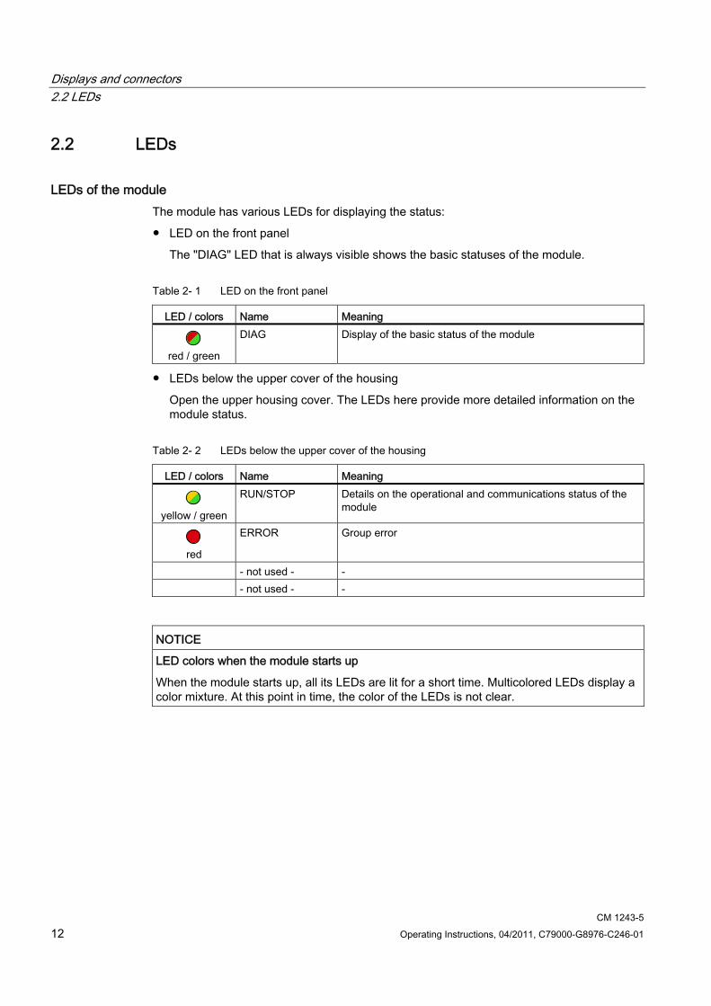
LEDs of the module The module has various LEDs for displaying the status:
● LED on the front panel
The "DIAG" LED that is always visible shows the basic statuses of the module.
Table 2- 1 LED on the front panel
LED / colors Name Meaning
red / green
DIAG Display of the basic status of the module
● LEDs below the upper cover of the housing
Open the upper housing cover. The LEDs here provide more detailed information on the module status.
Table 2- 2 LEDs below the upper cover of the housing
LED / colors Name Meaning
yellow / green
RUN/STOP Details on the operational and communications status of the module
red
ERROR Group error
- not used - - - not used - -
NOTICE LED colors when the module starts up
When the module starts up, all its LEDs are lit for a short time. Multicolored LEDs display a color mixture. At this point in time, the color of the LEDs is not clear.
Displays and connectors 2.2 LEDs
CM 1243-5 Operating Instructions, 04/2011, C79000-G8976-C246-01 13
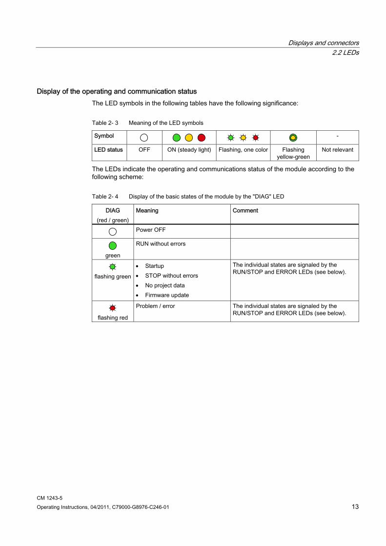
Display of the operating and communication status The LED symbols in the following tables have the following significance:
Table 2- 3 Meaning of the LED symbols
Symbol -
LED status OFF ON (steady light) Flashing, one color Flashing yellow-green
Not relevant
The LEDs indicate the operating and communications status of the module according to the following scheme:
Table 2- 4 Display of the basic states of the module by the "DIAG" LED
DIAG (red / green)
Meaning Comment
Power OFF
green
RUN without errors
flashing green
Startup STOP without errors No project data Firmware update
The individual states are signaled by the RUN/STOP and ERROR LEDs (see below).
flashing red
Problem / error The individual states are signaled by the RUN/STOP and ERROR LEDs (see below).
Displays and connectors 2.2 LEDs
CM 1243-5 14 Operating Instructions, 04/2011, C79000-G8976-C246-01
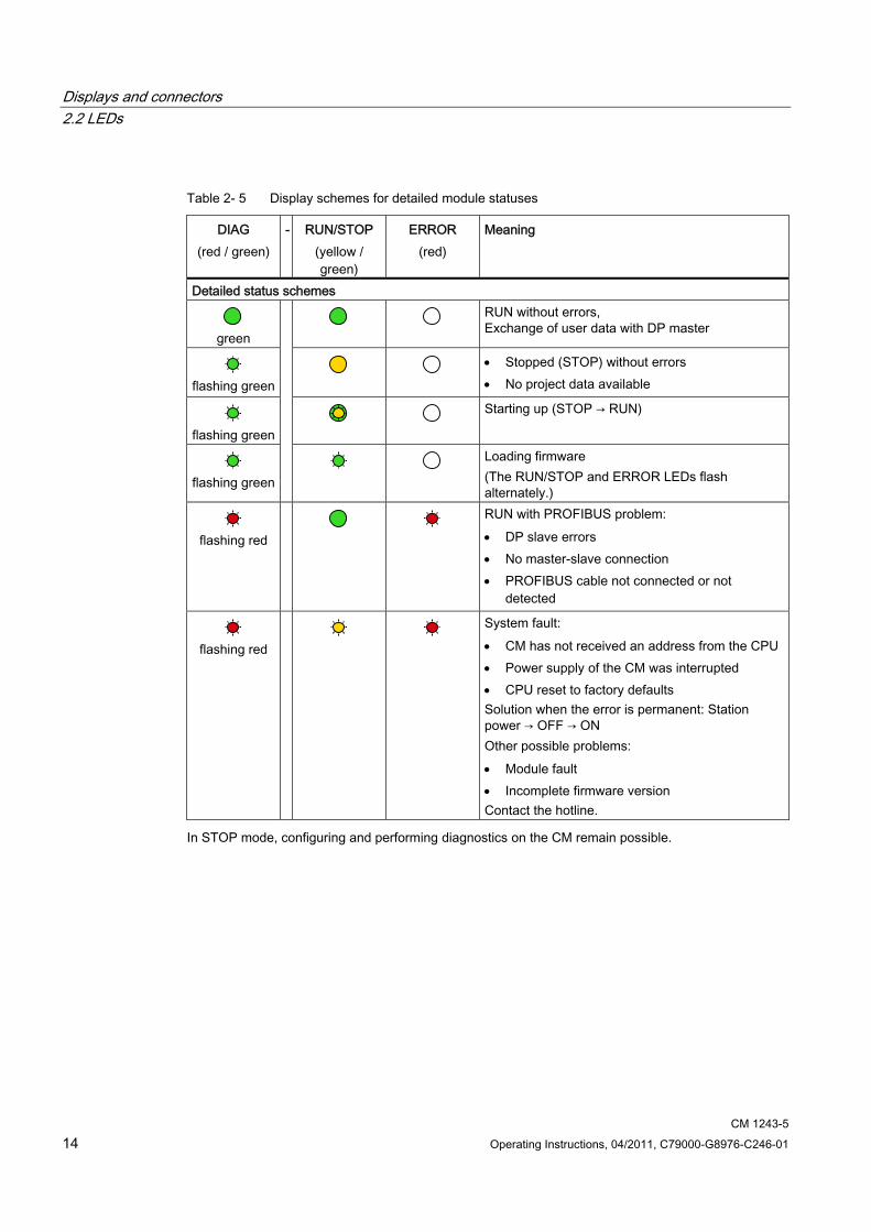
Table 2- 5 Display schemes for detailed module statuses
DIAG (red / green)
- RUN/STOP (yellow / green)
ERROR (red)
Meaning
Detailed status schemes
green
RUN without errors, Exchange of user data with DP master
flashing green
Stopped (STOP) without errors No project data available
flashing green
Starting up (STOP → RUN)
flashing green
Loading firmware (The RUN/STOP and ERROR LEDs flash alternately.)
flashing red
RUN with PROFIBUS problem: DP slave errors No master-slave connection PROFIBUS cable not connected or not
detected
flashing red
System fault: CM has not received an address from the CPU Power supply of the CM was interrupted CPU reset to factory defaults Solution when the error is permanent: Station power → OFF → ON Other possible problems: Module fault Incomplete firmware version Contact the hotline.
In STOP mode, configuring and performing diagnostics on the CM remain possible.
Displays and connectors 2.3 Electrical connections
CM 1243-5 Operating Instructions, 04/2011, C79000-G8976-C246-01 15
2.3 Electrical connections
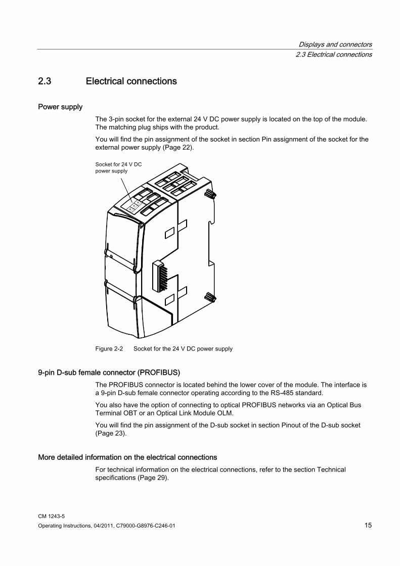
Power supply The 3-pin socket for the external 24 V DC power supply is located on the top of the module. The matching plug ships with the product.
You will find the pin assignment of the socket in section Pin assignment of the socket for the external power supply (Page 22).
Figure 2-2 Socket for the 24 V DC power supply
9-pin D-sub female connector (PROFIBUS) The PROFIBUS connector is located behind the lower cover of the module. The interface is a 9-pin D-sub female connector operating according to the RS-485 standard.
You also have the option of connecting to optical PROFIBUS networks via an Optical Bus Terminal OBT or an Optical Link Module OLM.
You will find the pin assignment of the D-sub socket in section Pinout of the D-sub socket (Page 23).
More detailed information on the electrical connections For technical information on the electrical connections, refer to the section Technical specifications (Page 29).

Displays and connectors 2.3 Electrical connections
CM 1243-5 16 Operating Instructions, 04/2011, C79000-G8976-C246-01
CM 1243-5 Operating Instructions, 04/2011, C79000-G8976-C246-01 17
Installing, connecting up and commissioning 3
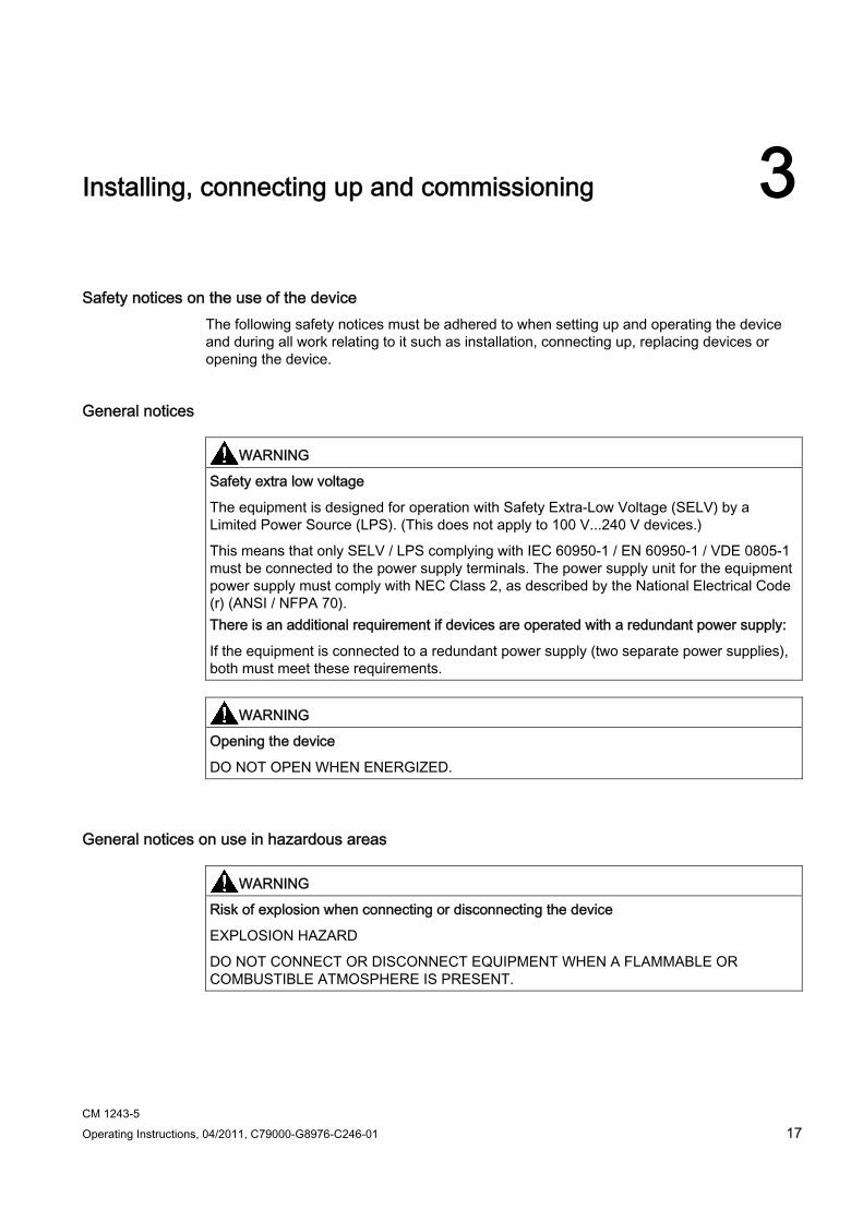
Safety notices on the use of the device The following safety notices must be adhered to when setting up and operating the device and during all work relating to it such as installation, connecting up, replacing devices or opening the device.
General notices
WARNING Safety extra low voltage
The equipment is designed for operation with Safety Extra-Low Voltage (SELV) by a Limited Power Source (LPS). (This does not apply to 100 V...240 V devices.)
This means that only SELV / LPS complying with IEC 60950-1 / EN 60950-1 / VDE 0805-1 must be connected to the power supply terminals. The power supply unit for the equipment power supply must comply with NEC Class 2, as described by the National Electrical Code (r) (ANSI / NFPA 70). There is an additional requirement if devices are operated with a redundant power supply:
If the equipment is connected to a redundant power supply (two separate power supplies), both must meet these requirements.
WARNING Opening the device
DO NOT OPEN WHEN ENERGIZED.
General notices on use in hazardous areas
WARNING Risk of explosion when connecting or disconnecting the device
EXPLOSION HAZARD
DO NOT CONNECT OR DISCONNECT EQUIPMENT WHEN A FLAMMABLE OR COMBUSTIBLE ATMOSPHERE IS PRESENT.
Installing, connecting up and commissioning
CM 1243-5 18 Operating Instructions, 04/2011, C79000-G8976-C246-01
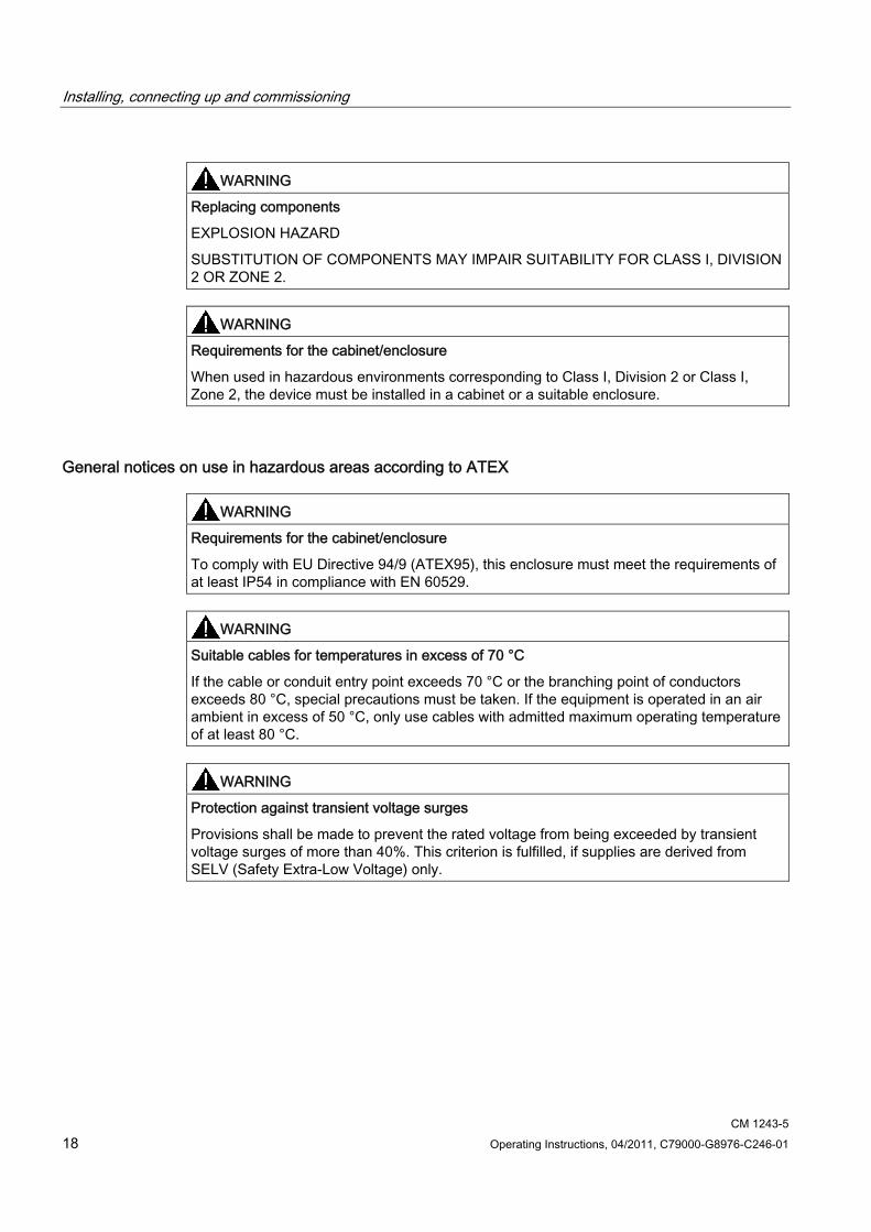
WARNING Replacing components
EXPLOSION HAZARD
SUBSTITUTION OF COMPONENTS MAY IMPAIR SUITABILITY FOR CLASS I, DIVISION 2 OR ZONE 2.
WARNING Requirements for the cabinet/enclosure
When used in hazardous environments corresponding to Class I, Division 2 or Class I, Zone 2, the device must be installed in a cabinet or a suitable enclosure.
General notices on use in hazardous areas according to ATEX
WARNING Requirements for the cabinet/enclosure
To comply with EU Directive 94/9 (ATEX95), this enclosure must meet the requirements of at least IP54 in compliance with EN 60529.
WARNING Suitable cables for temperatures in excess of 70 °C
If the cable or conduit entry point exceeds 70 °C or the branching point of conductors exceeds 80 °C, special precautions must be taken. If the equipment is operated in an air ambient in excess of 50 °C, only use cables with admitted maximum operating temperature of at least 80 °C.
WARNING Protection against transient voltage surges
Provisions shall be made to prevent the rated voltage from being exceeded by transient voltage surges of more than 40%. This criterion is fulfilled, if supplies are derived from SELV (Safety Extra-Low Voltage) only.

Installing, connecting up and commissioning 3.1 Warning overvoltage protection
CM 1243-5 Operating Instructions, 04/2011, C79000-G8976-C246-01 19
3.1 Warning overvoltage protection
CAUTION Protection of the external 24 VDC power supply
If power is supplied to the module over longer 24 V power cables or networks, the coupling in of strong electromagnetic pulses onto the power supply cables is possible. This can be caused, for example by lightning strikes or switching of higher loads.
The connector of the external 24 VDC power supply is not protected from strong electromagnetic pulses. To protect it, an external overvoltage protection module is necessary. A suitable device is, for example, the Dehn Blitzductor BVT AD 24V type no. 918 402 or comparable protective element.
Manufacturer: DEHN + SÖHNE GmbH + Co. KG, Hans-Dehn-Str. 1, PO box 1640, D-92306 Neumarkt
3.2 Installing and commissioning the CM 1243-5
Prior to installation and commissioning
WARNING Read the system manual "S7-1200 Programmable Controller"
Prior to installation, connecting up and commissioning, read the relevant sections in the system manual "S7-1200 Programmable Controller" (refer to the documentation in the Appendix).
When installing and connecting up, keep to the procedures described in the system manual "S7-1200 Programmable Controller".
Make sure that the power supply is turned off when installing/uninstalling the devices.
Configuration One requirement for the commissioning of the CP is the completeness of the STEP 7 project data. You should also read the section "Configuration and programming (Page 25)".
Installing, connecting up and commissioning 3.2 Installing and commissioning the CM 1243-5
CM 1243-5 20 Operating Instructions, 04/2011, C79000-G8976-C246-01
Dimensions for installation
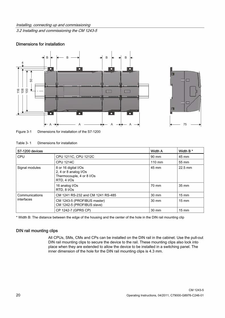
Figure 3-1 Dimensions for installation of the S7-1200
Table 3- 1 Dimensions for installation
S7-1200 devices Width A Width B * CPU 1211C, CPU 1212C 90 mm 45 mm CPU CPU 1214C 110 mm 55 mm 8 or 16 digital I/Os 2, 4 or 8 analog I/Os Thermocouple, 4 or 8 I/Os RTD, 4 I/Os
45 mm 22.5 mm Signal modules
16 analog I/Os RTD, 8 I/Os
70 mm 35 mm
CM 1241 RS-232 and CM 1241 RS-485 30 mm 15 mm CM 1243-5 (PROFIBUS master) CM 1242-5 (PROFIBUS slave)
30 mm 15 mm Communications interfaces
CP 1242-7 (GPRS CP) 30 mm 15 mm
* Width B: The distance between the edge of the housing and the center of the hole in the DIN rail mounting clip
DIN rail mounting clips All CPUs, SMs, CMs and CPs can be installed on the DIN rail in the cabinet. Use the pull-out DIN rail mounting clips to secure the device to the rail. These mounting clips also lock into place when they are extended to allow the device to be installed in a switching panel. The inner dimension of the hole for the DIN rail mounting clips is 4.3 mm.

Installing, connecting up and commissioning 3.2 Installing and commissioning the CM 1243-5
CM 1243-5 Operating Instructions, 04/2011, C79000-G8976-C246-01 21
Procedure for installation and commissioning
NOTICE Installation location
During installation, make sure that the upper and lower ventilation slits of the module are not obstructed and good ventilation is possible. Above and below the device, there must be a clearance of 25 mm to allow air to circulate and prevent overheating.
Remember that the permitted temperature ranges depend on the position of the installed device.
Device position / permitted temperature range Installation location Horizontal installation of the DIN rail: 0 °C to 55 °C
Vertical installation of the DIN rail: 0 °C to 45 °C
NOTICE Connection with power off
Only wire up the S7-1200 with the power turned off. Power supply from the power outputs of the CPU
The power of the CM must be supplied via the power outputs of the CPU.
Keep within the maximum load of the power outputs of the CPU.
You will find data relating to the current consumption and power loss of the CM in the section Technical specifications (Page 29). Grounding the PROFIBUS cable
If a CM 1243-5 is plugged into the S7-1200, a PROFIBUS cable must always be connected to the CM 1243-5. The PROFIBUS cable must be grounded.
Installing, connecting up and commissioning 3.3 Pin assignment of the socket for the external power supply
CM 1243-5 22 Operating Instructions, 04/2011, C79000-G8976-C246-01
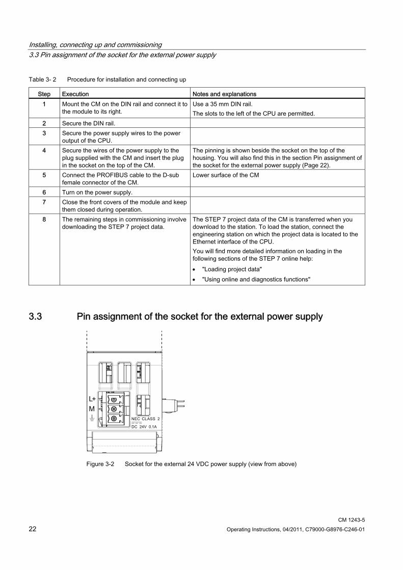
Table 3- 2 Procedure for installation and connecting up
Step Execution Notes and explanations 1 Mount the CM on the DIN rail and connect it to
the module to its right. Use a 35 mm DIN rail. The slots to the left of the CPU are permitted.
2 Secure the DIN rail. 3 Secure the power supply wires to the power
output of the CPU.
4 Secure the wires of the power supply to the plug supplied with the CM and insert the plug in the socket on the top of the CM.
The pinning is shown beside the socket on the top of the housing. You will also find this in the section Pin assignment of the socket for the external power supply (Page 22).
5 Connect the PROFIBUS cable to the D-sub female connector of the CM.
Lower surface of the CM
6 Turn on the power supply. 7 Close the front covers of the module and keep
them closed during operation.
8 The remaining steps in commissioning involve downloading the STEP 7 project data.
The STEP 7 project data of the CM is transferred when you download to the station. To load the station, connect the engineering station on which the project data is located to the Ethernet interface of the CPU. You will find more detailed information on loading in the following sections of the STEP 7 online help: "Loading project data" "Using online and diagnostics functions"
3.3 Pin assignment of the socket for the external power supply
Figure 3-2 Socket for the external 24 VDC power supply (view from above)
Installing, connecting up and commissioning 3.4 Pinout of the D-sub socket
CM 1243-5 Operating Instructions, 04/2011, C79000-G8976-C246-01 23
Table 3- 3 Pin assignment of the socket for the external power supply
Pin Labeling Function 1 L+ + 24 VDC 2 M Ground reference for + 24 VDC 3
Ground connector
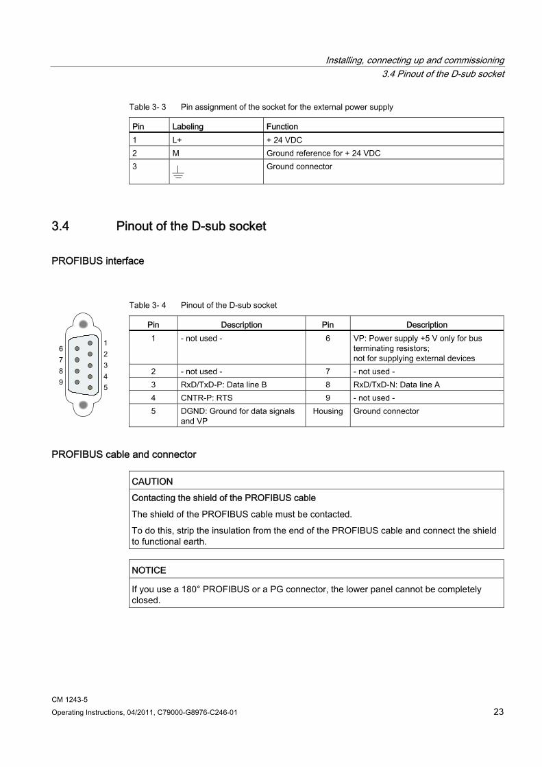
3.4 Pinout of the D-sub socket
PROFIBUS interface
Table 3- 4 Pinout of the D-sub socket
Pin Description Pin Description 1 - not used - 6 VP: Power supply +5 V only for bus
terminating resistors; not for supplying external devices
2 - not used - 7 - not used - 3 RxD/TxD-P: Data line B 8 RxD/TxD-N: Data line A 4 CNTR-P: RTS 9 - not used - 5 DGND: Ground for data signals
and VP Housing Ground connector
PROFIBUS cable and connector
CAUTION Contacting the shield of the PROFIBUS cable
The shield of the PROFIBUS cable must be contacted.
To do this, strip the insulation from the end of the PROFIBUS cable and connect the shield to functional earth.
NOTICE If you use a 180° PROFIBUS or a PG connector, the lower panel cannot be completely closed.

Installing, connecting up and commissioning 3.4 Pinout of the D-sub socket
CM 1243-5 24 Operating Instructions, 04/2011, C79000-G8976-C246-01
CM 1243-5 Operating Instructions, 04/2011, C79000-G8976-C246-01 25
Configuration and programming 44.1 Configuration
Configuration in STEP 7 You configure the DP modules and DP master systems in SIMATIC STEP 7. You will find the required version in the preface of this manual.
You can configure a maximum of three CMs/CPs per station, of which only one may be a DP master (CM 1243-5).
Overview of the STEP 7 configuration Follow the steps below when configuring:
1. Create a STEP 7 project.
2. Insert the required SIMATIC stations.
3. Insert the communications modules and other required modules in the stations.
4. Select the PROFIBUS interface of the master module and create a DP master system using the shortcut menu (right mouse button).
5. Configure the DP master system in the following parameter groups:
– General
– Network settings
– Cable configuration
– Additional network nodes
– Bus parameters
6. Network the PROFIBUS slaves with the master system:
– Either using the shortcut menu command with the PROFIBUS interface selected
– Or in the "Operating mode" parameter group of the slave module
7. Configure the slave modules.
Configuring the DP slaves is described in the manual of the slave module.
8. Configure the PROFIBUS master module.
This affects the properties in the following parameter groups:
– General
– PROFIBUS interface with the lower-level parameter groups "General" and "PROFIBUS address". The "Mode" of the DP master is preset.
9. Configure the remaining modules and submodules according to your requirements.
10. Save the project.
Configuration and programming 4.2 Programming
CM 1243-5 26 Operating Instructions, 04/2011, C79000-G8976-C246-01
Note
You will find more detailed information on configuring the individual parameters in the help system of STEP 7.
Downloading project data When you load the station, the project data of the CM is stored on the CPU.
4.2 Programming
DP data exchange with the CPU No instructions are necessary for GP data exchange with the CPU. The cyclically transferred slave data is written to the input and output areas of the CPU.
Reading and writing consistent data of a standard slave With the DPRD_DAT and DPWR_DAT instructions, you can read consistent data with a length of > 4 bytes from a slave or transfer consistent data to a slave.
Receiving interrupts with RALRM The RALRM instruction is used to receive interrupts from DP slaves and the corresponding information is indicated by the output parameters of the instruction.
Reading and writing a data record with the RDREC and WRREC instructions The "RDREC" and "WRREC" instructions are available for transferring configuration, diagnostics or I/O data.
S7 communication: Data exchange with remote communications partners The CM can communicate with remote partners via PROFIBUS. The following instructions are used:
● PUT: Instruction for writing data to a remote CPU or a remote PC
● GET: Instruction for reading data from a remote CPU or a remote PC
Remote communications partners can be S7-CPUs, PCs, PGs, TDs/OPs or SCADA systems, such as WinCC.
Note Information on the instructions
You will find information on the instructions mentioned above in the STEP 7 help.
CM 1243-5 Operating Instructions, 04/2011, C79000-G8976-C246-01 27
Operating the module 55.1 Note on operation
CAUTION Closing the front panels
To ensure interference-free operation, keep the front panels of the module closed during operation.
5.2 Diagnostics
Diagnostics options You have the following diagnostics options available for the module:
● The LEDs of the module
For information on the LED displays, refer to the section LEDs (Page 12).
● STEP 7: The "Diagnostics" tab in the Inspector window
Here, you can obtain the following information on the selected module:
– Entries in the diagnostics buffer of the CPU
– Information on the online status of the module
● STEP 7: Diagnostics functions in the "Online > Online and diagnostics" menu
Here, you can obtain static information on the selected module:
– General information on the module
– Diagnostics status
– Information about the PROFIBUS interface: - Settings - Statistics - Node list with PROFIBUS address and response on PROFIBUS
You can obtain further information on the diagnostics functions of STEP 7 in the STEP 7 online help.
Operating the module 5.3 Downloading firmware
CM 1243-5 28 Operating Instructions, 04/2011, C79000-G8976-C246-01
● DP diagnostics
You will find the description of the functions of DP diagnostics in the documentation of the relevant slave (for example, the manual of the CM 1242-5).
The evaluation of diagnostics data records requested by the DP master and the diagnostics interrupts or diagnostics alarms of the DP slaves is handled in the user program of the DP master station.
5.3 Downloading firmware
New firmware versions If a new firmware version is available for the module, you will find this on the Ethernet pages of the Siemens Automation Customer Support under the following ID:
44632196 (http://support.automation.siemens.com/WW/view/en/44632196)
On the Internet page, select the "Entry list" tab and the "Download" entry type. You will find the firmware file and a description of the procedure there.
You can recognize that firmware is being loaded by the flashing LEDs of the CM, see section LEDs (Page 12).
5.4 Module replacement
Module replacement The configuration data of the CM is stored on the local CPU. This allows simple replacement of this communications module when necessary.
When the station starts up again, the new CM reads the project data from the CPU.
WARNING Read the system manual "S7-1200 Programmable Controller"
Prior to installation, connecting up and commissioning, read the relevant sections in the system manual "S7-1200 Programmable Controller" (refer to the documentation in the Appendix).
When installing and connecting up, keep to the procedures described in the system manual "S7-1200 Programmable Controller".
Make sure that the power supply is turned off when installing/uninstalling the devices
CM 1243-5 Operating Instructions, 04/2011, C79000-G8976-C246-01 29
Technical specifications 6
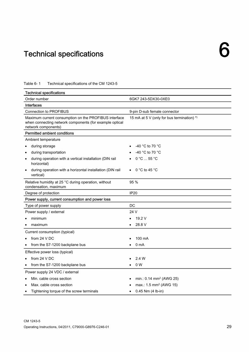
Table 6- 1 Technical specifications of the CM 1243-5
Technical specifications Order number 6GK7 243-5DX30-0XE0 Interfaces Connection to PROFIBUS 9-pin D-sub female connector Maximum current consumption on the PROFIBUS interface when connecting network components (for example optical network components)
15 mA at 5 V (only for bus termination) *)
Permitted ambient conditions Ambient temperature during storage during transportation during operation with a vertical installation (DIN rail
horizontal) during operation with a horizontal installation (DIN rail
vertical)
-40 °C to 70 °C -40 °C to 70 °C 0 °C ... 55 °C
0 °C to 45 °C
Relative humidity at 25 °C during operation, without condensation, maximum
95 %
Degree of protection IP20 Power supply, current consumption and power loss Type of power supply DC Power supply / external minimum maximum
24 V 19.2 V 28.8 V
Current consumption (typical) from 24 V DC from the S7-1200 backplane bus
100 mA 0 mA
Effective power loss (typical) from 24 V DC from the S7-1200 backplane bus
2.4 W 0 W
Power supply 24 VDC / external Min. cable cross section Max. cable cross section Tightening torque of the screw terminals
min.: 0.14 mm2 (AWG 25) max.: 1.5 mm2 (AWG 15) 0.45 Nm (4 lb-in)
Technical specifications
CM 1243-5 30 Operating Instructions, 04/2011, C79000-G8976-C246-01
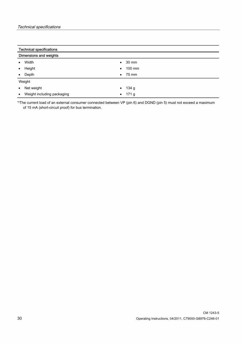
Technical specifications Dimensions and weights
Width Height Depth
30 mm 100 mm 75 mm
Weight Net weight Weight including packaging
134 g 171 g
*)The current load of an external consumer connected between VP (pin 6) and DGND (pin 5) must not exceed a maximum of 15 mA (short-circuit proof) for bus termination.
CM 1243-5 Operating Instructions, 04/2011, C79000-G8976-C246-01 31
Dimension drawings A
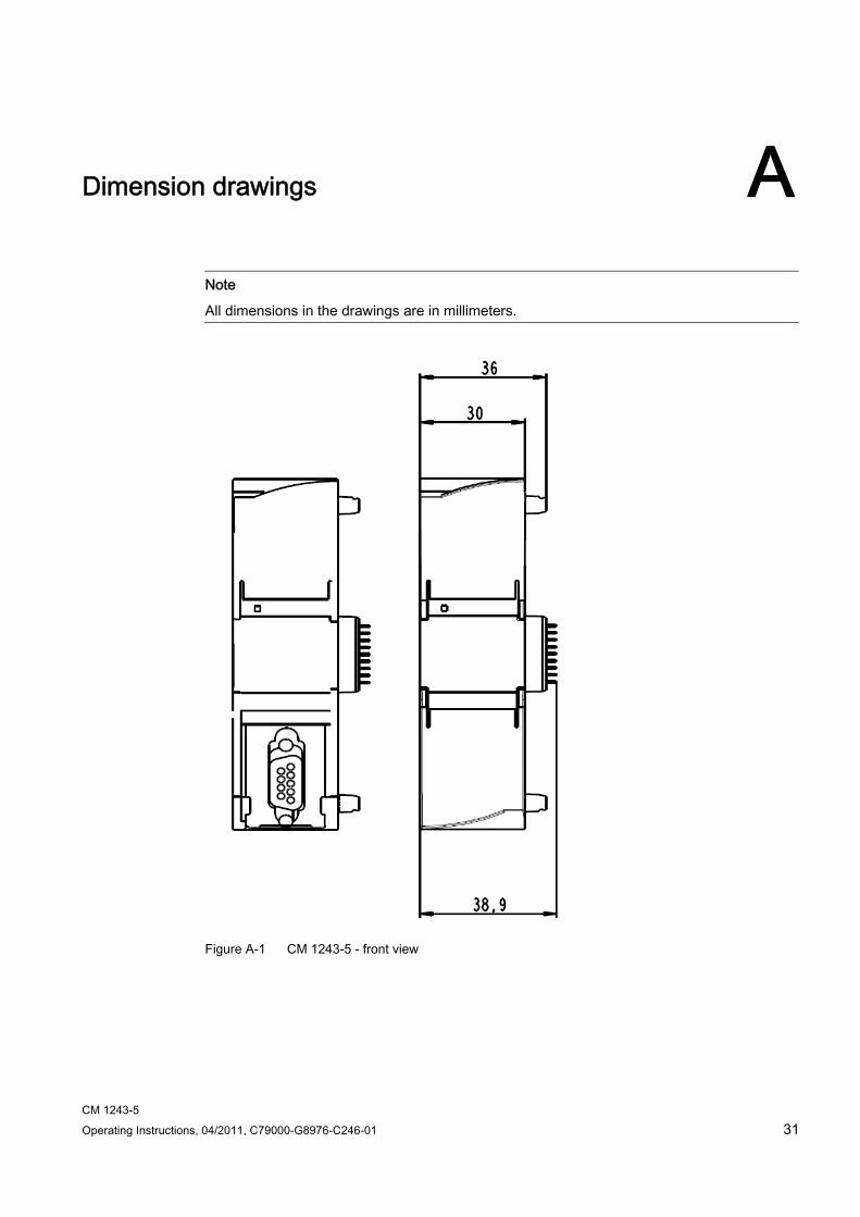
Note
All dimensions in the drawings are in millimeters.
Figure A-1 CM 1243-5 - front view
Dimension drawings
CM 1243-5 32 Operating Instructions, 04/2011, C79000-G8976-C246-01
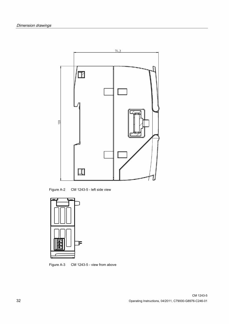
Figure A-2 CM 1243-5 - left side view
Figure A-3 CM 1243-5 - view from above
CM 1243-5 Operating Instructions, 04/2011, C79000-G8976-C246-01 33
Approvals B
National approvals The list of countries in which the CM 1243-5 is approved can be found on the Internet at the following address:
44632657 (http://support.automation.siemens.com/WW/view/en/http://support.automation.siemens.com/WW/view/de/44632650) → "Entry list" tab > entry type "Certificates"
Overview of approvals and standards The CM 1243-5 has the following approvals and meets the following standards:
● cULus LISTED IND. CONT. EQ. for HAZ.LOC.
cULus LISTED IND. CONT. EQ.
● FM
● ATEX: KEMA 03 ATEX 1228X
● CE declaration of conformity
– EU Directive 2004/108/EEC "Electromagnetic Compatibility" (EMC Directive)
– EU Directive 2002/95/EC (RoHS)
● C-TICK
● Use in industrial environments according to:
– EN 61000-6-4:2007
– EN 61000-6-2:2005
Approvals issued
NOTICE Issued approvals on the type plate of the device
The specified approvals apply only when the corresponding mark is printed on the product. You can check which of the following approvals have been granted for your product by the markings on the type plate.
Approvals
CM 1243-5 34 Operating Instructions, 04/2011, C79000-G8976-C246-01
Standards and test specifications The product meets the following standards and test specifications. The test criteria for the module are based on these standards and test specifications.
CE declaration of conformity
The product meets the requirements and safety objectives of the following EU directives and it complies with the harmonized European standards (EN) for programmable logic controllers which are published in the official documentation of the European Union.
● EU directive 2006/95/EEC "Electrical Equipment Designed for Use within Certain Voltage Limits" (Low Voltage Equipment Directive)
– EN 61131-2:2007 Programmable controllers - Equipment requirements and tests
● EU Directive 2004/108/EEC "Electromagnetic Compatibility" (EMC Directive)
– Emission EN 61000-6-4:2007: Industrial area
– Immunity EN 61000-6-2:2005: Industrial area
● EU directive 94/9/EC "Equipment and protective systems intended for use in potentially explosive atmospheres" (ATEX Explosion Protection Directive)
– EN 60079-15:2005: Type of protection 'n':
The EC Declaration of Conformity is available for all responsible authorities at:
Siemens Aktiengesellschaft Industry Automation Industrielle Kommunikation SIMATIC NET Postfach 4848 D-90327 Nürnberg Germany
You will find the EC Declaration of Conformity for this product on the Internet at the following address:
10805878 (http://support.automation.siemens.com/WW/view/en/10805878) → Tab "Entry List"
Filter settings: Entry type: "Certificates" Certificate Type: "Declaration of Conformity" Search items(s): <name of the module>
Approvals
CM 1243-5 Operating Instructions, 04/2011, C79000-G8976-C246-01 35
cULus approval
Underwriters Laboratories Inc. meets Underwriters Laboratories, Inc.: UL 508 Listed (industrial control
devices) Canadian Standards Association: CSA C22.2 Number 142
(process control equipment)
FM certification
Factory Mutual Research (FM): certification standard class number 3600 and 3611 Approved for use in: Class I, Division 2, Gas Group A, B, C, D, Temperature Class T4A, Ta = 40°C Class I, Zone 2, IIC, Temperature Class T4, Ta = 40°C
ATEX approval
EN 60079-0:2006: Potentially explosive atmosphere - general requirements EN 60079-15:2005: Electrical apparatus for explosive gas atmospheres; Type of protection 'n' II 3 G Ex nA II T4
Over and above this, the following conditions must be met for the safe deployment of the product:
● Install the modules in a suitable enclosure with degree of protection of at least IP54 to EN 60529 and take into account the environmental conditions for operation of the devices.
● If the rated temperatures of 70°C at the cable entry or 80°C at the branching point of the wires are exceeded, the permitted temperature range of the selected cable must be suitable for the actual measured temperatures.
● Measures must be taken to prevent the rated voltage being exceeded by more than 40% due to transient disturbances.
C-Tick approval
The product meets the requirements of the AS/NZS 2064 standards (Class A)
Approvals
CM 1243-5 36 Operating Instructions, 04/2011, C79000-G8976-C246-01
Maritime approvals The S7-1200 products are regularly submitted to the relevant authorities for approvals relating to specific markets and applications. If you require a list of the current approvals for individual devices, consult your Siemens contact.
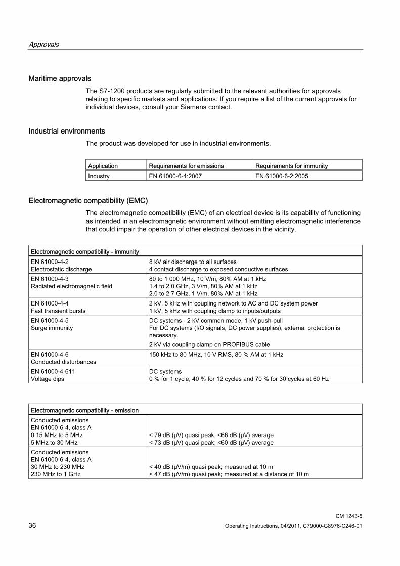
Industrial environments The product was developed for use in industrial environments.
Application Requirements for emissions Requirements for immunity Industry EN 61000-6-4:2007 EN 61000-6-2:2005
Electromagnetic compatibility (EMC) The electromagnetic compatibility (EMC) of an electrical device is its capability of functioning as intended in an electromagnetic environment without emitting electromagnetic interference that could impair the operation of other electrical devices in the vicinity.
Electromagnetic compatibility - immunity EN 61000-4-2 Electrostatic discharge
8 kV air discharge to all surfaces 4 contact discharge to exposed conductive surfaces
EN 61000-4-3 Radiated electromagnetic field
80 to 1 000 MHz, 10 V/m, 80% AM at 1 kHz 1.4 to 2.0 GHz, 3 V/m, 80% AM at 1 kHz 2.0 to 2.7 GHz, 1 V/m, 80% AM at 1 kHz
EN 61000-4-4 Fast transient bursts
2 kV, 5 kHz with coupling network to AC and DC system power 1 kV, 5 kHz with coupling clamp to inputs/outputs
EN 61000-4-5 Surge immunity
DC systems - 2 kV common mode, 1 kV push-pull For DC systems (I/O signals, DC power supplies), external protection is necessary. 2 kV via coupling clamp on PROFIBUS cable
EN 61000-4-6 Conducted disturbances
150 kHz to 80 MHz, 10 V RMS, 80 % AM at 1 kHz
EN 61000-4-611 Voltage dips
DC systems 0 % for 1 cycle, 40 % for 12 cycles and 70 % for 30 cycles at 60 Hz
Electromagnetic compatibility - emission Conducted emissions EN 61000-6-4, class A 0.15 MHz to 5 MHz 5 MHz to 30 MHz
< 79 dB (μV) quasi peak; <66 dB (μV) average < 73 dB (μV) quasi peak; <60 dB (μV) average
Conducted emissions EN 61000-6-4, class A 30 MHz to 230 MHz 230 MHz to 1 GHz
< 40 dB (μV/m) quasi peak; measured at 10 m < 47 dB (μV/m) quasi peak; measured at a distance of 10 m
Approvals
CM 1243-5 Operating Instructions, 04/2011, C79000-G8976-C246-01 37
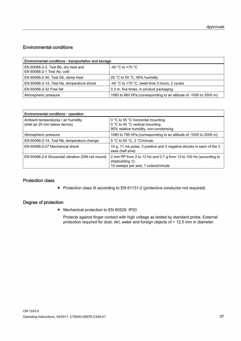
Environmental conditions Environmental conditions - transportation and storage EN 60068-2-2, Test Bb, dry heat and EN 60068-2-1 Test Ab, cold
-40 °C to +70 °C
EN 60068-2-30, Test Db, damp heat 25 °C to 55 °C, 95% humidity EN 60068-2-14, Test Na, temperature shock -40 °C to +70 °C, dwell time 3 hours, 2 cycles EN 60068-2-32 Free fall 0.3 m, five times, in product packaging Atmospheric pressure 1080 to 660 hPa (corresponding to an altitude of -1000 to 3500 m)
Environmental conditions - operation Ambient temperatures / air humidity (inlet air 25 mm below device)
0 °C to 55 °C horizontal mounting 0 °C to 45 °C vertical mounting 95% relative humidity, non-condensing
Atmospheric pressure 1080 to 795 hPa (corresponding to an altitude of -1000 to 2000 m) EN 60068-2-14, Test Nb, temperature change 5 °C to 55 °C, 3 °C/minute EN 60068-2-27 Mechanical shock 15 g, 11 ms pulse, 3 positive and 3 negative shocks in each of the 3
axes (half sine) EN 60068-2-6 Sinusoidal vibration (DIN rail mount) 2 mm PP from 2 to 13 Hz and 0.7 g from 13 to 100 Hz (according to
shipbuilding 1); 10 sweeps per axis, 1 octave/minute
Protection class ● Protection class III according to EN 61131-2 (protective conductor not required)
Degree of protection ● Mechanical protection to EN 60529: IP20
Protects against finger contact with high voltage as tested by standard probe. External protection required for dust, dirt, water and foreign objects of < 12.5 mm in diameter.

Approvals
CM 1243-5 38 Operating Instructions, 04/2011, C79000-G8976-C246-01
CM 1243-5 Operating Instructions, 04/2011, C79000-G8976-C246-01 39
References C
Where to find Siemens documentation ● You will find the order numbers for the Siemens products of relevance here in the
following catalogs:
– SIMATIC NET Industrial Communication / Industrial Identification, catalog IK PI
– SIMATIC Products for Totally Integrated Automation and Micro Automation, catalog ST 70
You can request the catalogs and additional information from your Siemens representative.
● You will find SIMATIC NET manuals on the Internet pages of Siemens Automation Customer Support:
Link to Customer Support (http://support.automation.siemens.com/WW/view/en)
Enter the entry ID of the relevant manual as the search item. The ID is listed below some of the reference entries in brackets.
As an alternative, you will find the SIMATIC NET documentation on the pages of Product Support:
10805878 (http://support.automation.siemens.com/WW/view/en/10805878)
Go to the required product group and make the following settings:
→ Entry list → Entry type "Manuals / Operating Instructions"
You will find the documentation for the SIMATIC NET products relevant here on the data medium that ships with the SIMATIC NET products:
– Product DVD (SIMATIC NET CM/CP for S7-1200)
– SIMATIC NET Manual Collection. This DVD ships with every S7-300/400 CP.
/1/ SIMATIC S7-1200 Programmable Controller System Manual Siemens AG order number: 6ES7298-8FA30-8BH0 Entry ID: 36932465 (http://support.automation.siemens.com/WW/view/en/36932465)

References 0 /2/
CM 1243-5 40 Operating Instructions, 04/2011, C79000-G8976-C246-01
/2/ SIMATIC NET PROFIBUS Network Manual system manual Siemens AG Entry ID: 35222591 (http://support.automation.siemens.com/WW/view/en/35222591)
CM 1243-5 Operating Instructions, 04/2011, C79000-G8976-C246-01 41
Training, Service & Support D
Online support In addition to our product documentation, the comprehensive online information platform supports you in all aspects of our Service & Support at any time and from any location in the world. You will find this on the Internet at the following address: (http://support.automation.siemens.com/WW/llisapi.dll?func=cslib.csinfo2&aktprim=99&lang=en)
Here, you will find the following information:
● Support news, newsletter
● Product information, Product Support, Applications & Tools
● Technical Forum
● Access to other features of our Service & Support offer:
– Technical Consulting
– Engineering Support
– Field Service
Phone: +49 (0)911 895 7444
– Spare parts and repairs
Phone: +49 (0)911 895 7448
– Optimization and modernization
– Technical Support
Expert advice on technical questions with a wide range of demand-optimized services for all our products and systems.
Phone: +49 (0)911 895 7222 (https://support.automation.siemens.com/WW/llisapi.dll?func=cslib.csinfo&lang=en&objid=38718979&caller=view)
You will find contact data on the Internet at the following address: (www.automation.siemens.com/partner)
Training, Service & Support
CM 1243-5 42 Operating Instructions, 04/2011, C79000-G8976-C246-01
SITRAIN - Siemens training for automation and industrial solutions With over 300 different courses, SITRAIN covers the entire Siemens product and system spectrum in the field of automation and drive technology. Advanced training tailored to your needs is also available. In addition to our classic range of courses, we also offer a combination of various training media and sequences. You can, for example, use self-study programs on CD-ROM or on the Internet as preparation or to consolidate training.
You will find detailed information on our training curriculum and how to contact our customer consultants at the following Internet address:
(www.siemens.com/sitrain)
CM 1243-5 Operating Instructions, 04/2011, C79000-G8976-C246-01 43
Glossary
Bus parameter Special parameters that control transfer characteristics on the bus. Each PROFIBUS node must use bus parameters that match the bus parameters of other nodes.
CLEAR mode Mode of the DP master; inputs are read cyclically, outputs remain set to 0.
CM Communications module
Module for communications tasks that is used in an automation system as an interface expansion of the CPU. Same interface types of a CPU and a CM are functionally identical.
Contol job Control command for DP mode.
Examples: CLEAR, SYNC, FREEZE, UNFREEZE, ACT, DEACT.
CP Communications processor
Module for expanded communications tasks that provides the CPU with additional interface types or communications options.
DP I/O module Component of a DP slave. DP slaves have a modular structure. A DP slave has at least one DP I/O module.
DP master A node with master functionality on PROFIBUS DP. The following must be distinguished:
DP master (class 1) or DP master 1 The DP master 1 handles user data traffic with the DP slaves assigned to it.
Glossary
CM 1243-5 44 Operating Instructions, 04/2011, C79000-G8976-C246-01
DP master (class 2) or DP master 2 The DP master 2 provides services such as : − Reading input/output data − Diagnostics − Global control
DP master system A DP master and all DP slaves with which this DP master exchanges data.
DP mode Communication between the DP master and DP slaves can be divided into four modes: OFFLINE, STOP, CLEAR, RUN (corresponds to OPERATE according to the DP standard).
Each of these modes is characterized by defined actions between the DP master and the DP slaves.
DP module name Name of one of the DP I/O modules entered in the DP module list.
DP module type Name to identify a DP I/O module in the generic station data of a DP slave in compliance with EN 50170, Vol 2.
DP protocol The rules for communication and data transmission according to the communications standard for the field area (IEC 61158) and PROFIBUS standard (EN 50170).
Note: The DP protocol is used in the distributed peripheral I/O (DP) and allows distributed use of numerous modules and other field devices in the immediate vicinity of the process.
DP slave A node with slave functionality on PROFIBUS DP
DP slave name To identify a DP slave in the configured DP configuration, a DP slave name is entered in the DP slave list.
DP subnet PROFIBUS subnet on which only distributed I/O is operated.
Glossary
CM 1243-5 Operating Instructions, 04/2011, C79000-G8976-C246-01 45
FREEZE mode The FREEZE mode is a DP mode in which process input data is obtained at the same time from one or more (group) or from all DP slaves. The time of acquisition is signaled by the FREEZE command (this is a control frame for synchronization).
Generic station data GSD
This contains DP slave descriptions according to EN 50170, Vol 2. The use of GSD simplifies configuration of the DP master and DP slaves.
Group identification Allows the assignment of DP slaves to one or more groups. The DP slaves can be addressed specifically when transferring control frames using the group identification.
SYNC mode A DP mode in which one, several (group) or all DP slaves transfer data to their process outputs at a certain time. The time at which the data is transferred is indicated in the SYNC command (a control command for synchronization).
Target rotation time Target rotation time
A bus parameter for PROFIBUS. The token rotation time that should be kept to.
Note: A station compares the actual token rotation time it has measured with the target rotation time and, depending on the result, can then send high or low priority frames.
UNFREEZE Job for resetting the FREEZE mode.
UNSYNC Job for resetting the SYNC mode.
Watchdog time A monitoring time that can be set on a DP slave to detect failure of the controlling DP master.

Glossary
CM 1243-5 46 Operating Instructions, 04/2011, C79000-G8976-C246-01
CM 1243-5 Operating Instructions, 04/2011, C79000-G8976-C246-01 47
Index
A ATEX, 18 ATEX approval, 35
C CPU firmware version, 10
D Degree of protection, 37 Dimensions, 20, 30 Downloading project data, 22, 26
E Electromagnetic compatibility (EMC), 36 EMC, 36 Environment, industry, 36 Environmental conditions, 37
F Firmware version, 3
H Hardware product version, 3 Hazardous area, 17
O Operating states, 13
P Protection class, 37
R Replacing a module, 28
S Safety notices, 17 STEP 7 version, 10 SYNC / FREEZE, 8

Index
CM 1243-5 48 Operating Instructions, 04/2011, C79000-G8976-C246-01