Embed Size (px)
Citation preview
s
Process Control System PCS 7 Engineering Compendium Part B Process Safety Preliminary Draft V2.0
Preface Contents
Installing the fail-safe system 1 ES settings 2 S7F/FH hardware parameterization 3 Configuring the safety program 4 Configuring fail-safe AS-AS communication 5 Configuring F-block types 6 Configuration with Safety Matrix 7 System Acceptance Test 8 Maintenance and diagnostics 9
SIMATIC
Process Control System PCS 7 Engineering Compendium Part B Process Safety Manual
02/2008 Preliminary Draft V2.0
Siemens AG Automation and Drives PO Box 4848 90437 NUREMBERG GERMANY
Preliminary Draft V2.0 02/2008
Copyright © Siemens AG 2007 Modifications reserved
Safety instructions This manual contains instructions intended to ensure personal safety, as well as to protect equipment against damage. Instructions relating to your personal safety are indicated by a warning triangle, which does not appear with instructions solely relating to material damage. Warning notices appear as shown below, in descending order of hazard priority.
! Danger indicates that death or severe personal injury will result if proper precautions are not taken.
! Warning indicates that death or severe personal injury may result if proper precautions are not taken.
! Caution with a warning triangle indicates that minor personal injury may result if proper precautions are not taken.
Caution
without a warning triangle indicates that property damage may result if proper precautions are not taken.
Notice indicates that an unwanted result or state may occur if the relevant instruction is not observed.
If several hazard levels are applicable, the warning notice corresponding to the highest level is always used. If a warning notice with a warning triangle relates to the risk of personal injury, a warning relating to material damage may also be added to that same warning notice.
Qualified Personnel The equipment/system to which this documentation applies must always be set up and operated in accordance with this manual. Only qualified personnel should be allowed to commission and work on this equipment/system. Qualified personnel, as used in the safety-related information in this documentation, is defined as persons who are authorized to commission, to ground, and to tag equipment, systems and circuits in accordance with established safety practices and standards.
Correct Usage
Note the following:
! Warning The equipment may only be used for the applications described in the catalog and the technical description, and only in conjunction with equipment or components from other manufacturers which have been approved or recommended by Siemens. This product can only function correctly and safely if it is transported, stored, assembled, and installed correctly, and operated and maintained as recommended.
Trademarks All product names marked with the ® copyright symbol are trademarks of Siemens AG. Other product names in this document may be trademarks and third parties using these names for their own purposes may infringe upon the rights of the trademark owners.
Disclaimer of Liability We have checked the content of this manual for agreement with the hardware and software described. Since deviations cannot be precluded entirely, we cannot guarantee full agreement. The information in this manual is reviewed regularly and any necessary corrections will be included in subsequent editions.
Process Control System PCS 7 Engineering Compendium Part B Process Safety Preliminary Draft V2.0 iii
Preface
Subject of the manual This manual serves as a design guide, to be used in addition to the SIMATIC PCS 7 product documentation. Essential engineering steps are described in form of operation instructions to a large extent.
Based on practical experience, the suggested solution process is meant to cover general essential needs to avoid frequently occurring problems.
The compendium is divided into three parts:
• Part A Standard
• Part B Process Safety
• Part C Equipment Modules
Parts B and C are based as optional extras for standard part A.
Preface
Process Control System PCS 7 Engineering Compendium Part B Process Safety iv Preliminary Draft V2.0
Additional support If this manual does not contain the answers to any questions you may have about how to use the products described, please contact your local Siemens representative.
You can locate your contact at:
http://www.siemens.com/automation/partner
The guide that provides details of the technical documentation offered for the individual SIMATIC products and systems is available at:
http://www.siemens.de/simatic-tech-doku-portal
The online catalog and online ordering system are available at:
http://mall.automation.siemens.com/
Training Center We offer appropriate courses to help you to familiarize yourself with the SIMATIC S7 automation system. Contact your regional Training Center or the Central Training Center in Nuremberg, Germany. Phone: +49 (911) 895-3200. Internet: http://www.sitrain.com
Technical Support Technical support for all A&D products can be accessed • via the online Support Request form at
http://www.siemens.de/automation/support-request • Phone: + 49 180 5050 222 • Fax: + 49 180 5050 223 Additional information on our technical support is available on the Internet at http://www.siemens.de/automation/service
Service & Support on the Internet In addition to our documentation options, our expertise is also available to you online. http://www.siemens.com/automation/service&support Here you will be able to access: • The newsletter, which will keep you constantly up-to-date with the latest
information about our products • The right documents via our Service & Support search facility • A forum that provides users and specialists with an international platform for
sharing experiences • Your local Automation & Drives representative
Information about local service, repairs, spare parts The "Our service offer" section offers even more options.
Contents
Process Control System PCS 7 Engineering Compendium Part B Process Safety Preliminary Draft V2.0 v
Contents
Preface iii
Contents v
1 Installing the fail-safe system 1-1 1.1 ES installation ................................................................................................... 1-1 1.1.1 F-systems .........................................................................................................1-1 1.1.2 Safety Matrix.....................................................................................................1-1 1.2 OS server installation........................................................................................ 1-2 1.2.1 F-systems .........................................................................................................1-2 1.2.2 Safety Matrix.....................................................................................................1-2 1.3 OS client installation ......................................................................................... 1-3 1.3.1 F-systems .........................................................................................................1-3 1.3.2 Safety Matrix.....................................................................................................1-3
2 ES settings 2-1 2.1 Access protection with SIMATIC Logon ........................................................... 2-1 2.2 Compiling.......................................................................................................... 2-2
3 S7F/FH hardware parameterization 3-1 3.1 CPU parameters (single F-system) .................................................................. 3-1 3.1.1 Password and access protection......................................................................3-1 3.1.2 Diagnostics/Clock .............................................................................................3-2 3.1.3 Memory.............................................................................................................3-3 3.2 CPU parameters (fault-tolerant F-system)........................................................ 3-4 3.2.1 Cyclic interrupts ................................................................................................3-4 3.2.2 H parameters ....................................................................................................3-5 3.3 Communications module parameters/Networks............................................... 3-9 3.4 I/O module system parameters ...................................................................... 3-10 3.4.1 Parameters/F-parameters...............................................................................3-10 3.4.2 Module parameter...........................................................................................3-12 3.4.3 DI8xNAMUR/DI24xDC24V binary inputs........................................................3-13 3.4.4 Binary output DO10xDC24V/2A .....................................................................3-15 3.4.5 Analog input F_AI 6x13 ..................................................................................3-17 3.4.6 Configuring redundant F-I/O...........................................................................3-20 3.4.7 Terminal Modules (MTAs) ..............................................................................3-22 3.5 "Wiring and Voting" architectures for ET200M F-AIs ..................................... 3-22 3.5.1 Voting with F-DI ..............................................................................................3-23 3.5.2 Voting with F-AI ..............................................................................................3-24
4 Configuring the safety program 4-1 4.1 Fail-safe application program ........................................................................... 4-1 4.2 Program structure of the safety program.......................................................... 4-2 4.3 Creating the safety program ............................................................................. 4-3 4.3.1 Requirements ...................................................................................................4-3 4.3.2 Defining the program structure .........................................................................4-3
Contents
Process Control System PCS 7 Engineering Compendium Part B Process Safety vi Preliminary Draft V2.0
4.3.3 Library...............................................................................................................4-4 4.3.4 Inserting CFC charts.........................................................................................4-4 4.3.5 Inserting fail-safe blocks ...................................................................................4-4 4.3.6 Assigning parameters to and interconnecting F-blocks....................................4-5 4.3.7 Run sequence of F-blocks................................................................................4-6 4.3.8 F-runtime groups ..............................................................................................4-7 4.3.9 F-shutdown groups ...........................................................................................4-9 4.3.10 How F-blocks with floating-point operations respond to number range overflows
........................................................................................................................4-10 4.4 F-STOP........................................................................................................... 4-12 4.4.1 Complete shutdown........................................................................................4-12 4.4.2 Partial shutdown .............................................................................................4-12 4.4.3 Parameter assignment for shutdown behavior ...............................................4-13 4.4.4 Causes of errors .............................................................................................4-14 4.4.5 Sequence of an F-STOP in S7 FH systems...................................................4-15 4.4.6 Exiting an F-STOP..........................................................................................4-16 4.5 F-startup and (re)start protection.................................................................... 4-16 4.5.1 F-startup .........................................................................................................4-16 4.5.2 (Re)start protection .........................................................................................4-16 4.6 Data exchange between F-shutdown groups................................................. 4-17 4.7 Passivation and reintegration of input/output modules................................... 4-21 4.7.1 Passivation .....................................................................................................4-21 4.7.2 Group passivation...........................................................................................4-22 4.7.3 Reintegration following elimination of errors...................................................4-22 4.7.4 Automatic reintegration...................................................................................4-23 4.7.5 Reintegration following user acknowledgment ...............................................4-24 4.7.6 Example implementation of F-user acknowledgment on the OS ...................4-25 4.8 Compiling the F-program................................................................................ 4-29 4.8.1 Password protection when compiling the safety program..............................4-29 4.8.2 Parameterizing the maximum F cycle time monitoring...................................4-30 4.8.3 Compiling the PCS 7 program........................................................................4-31 4.9 Safety mode and downloading the safety program........................................ 4-33 4.9.1 Deactivating safety mode ...............................................................................4-33 4.9.2 Activating safety mode....................................................................................4-35 4.9.3 Downloading the safety program....................................................................4-35 4.10 Displaying and reporting system states.......................................................... 4-37 4.10.1 Data exchange between the F-user program and the standard user program
(PCS) ..............................................................................................................4-37 4.10.2 System diagnostics using PCS 7 Asset Management ...................................4-40 4.11 Working with safety-relevant parameters ....................................................... 4-41 4.11.1 Safety Data Write (SDW)................................................................................4-41 4.11.2 Operator control via the OS with F-QUITES...................................................4-42 4.12 Monitoring times and system response times ................................................ 4-43 4.12.1 Calculating the F-cycle monitoring time (for block F_CYC_CO) ....................4-43 4.12.2 Communications monitoring time F-CPU - F-I/O............................................4-46 4.12.3 Monitoring time for safety-related communication between F-CPUs .............4-50 4.12.4 Monitoring communication between F-shutdown groups ...............................4-52 4.12.5 Response times of safety functions................................................................4-53
5 Configuring fail-safe AS-AS communication 5-1 5.1.1 How to configure S7 connections .....................................................................5-1 5.1.2 Configuring connections ...................................................................................5-2 5.1.3 Configuring F-communications blocks..............................................................5-4
6 Configuring F-block types 6-1
Contents
Process Control System PCS 7 Engineering Compendium Part B Process Safety Preliminary Draft V2.0 vii
6.1 Rules for F-block types..................................................................................... 6-1 6.2 Creating and modifying F-block types .............................................................. 6-2
7 Configuration with Safety Matrix 7-1 7.1 Safety Matrix Editor .......................................................................................... 7-2 7.1.1 Cause................................................................................................................7-2 7.1.2 Effect.................................................................................................................7-5 7.1.3 Intersection .......................................................................................................7-7 7.2 Safety Matrix Engineering Tool ........................................................................ 7-9 7.2.1 Options..............................................................................................................7-9 7.2.2 General information ........................................................................................7-10 7.2.3 Project Utilities (Transfer To Project)..............................................................7-11 7.2.4 OS integration.................................................................................................7-12 7.2.5 Online mode ...................................................................................................7-13 7.2.6 Status display .................................................................................................7-15
8 System Acceptance Test 8-1 8.1 Overview of system acceptance test ................................................................ 8-1 8.2 Commissioning a safety program..................................................................... 8-1 8.2.2 Preliminary test of the configuration of the F-CPU and F-I/O (optional)...........8-1 8.2.3 Printing hardware configuration data................................................................8-2 8.2.4 Checking hardware configuration data .............................................................8-2 8.2.5 Backup of the STEP 7 project ..........................................................................8-4 8.2.6 Inspection of the printout ..................................................................................8-4 8.2.7 Check of safety-related parameters .................................................................8-4 8.3 Acceptance test of safety program changes .................................................... 8-5 8.3.1 Checking the overall signature .........................................................................8-5 8.4 Abnahme von F-Bausteintypen ........................................................................ 8-6 8.4.1 Initial acceptance test .......................................................................................8-6 8.4.2 Acceptance test of changes .............................................................................8-6 8.4.3 Modified calculation of signatures of F-Block types with the Failsafe Blocks F-
Library (V1_2) ...................................................................................................8-6 9 Maintenance and diagnostics 9-1
9.1 Tracking changes in the safety program .......................................................... 9-1 9.1.1 Overall signature...............................................................................................9-1 9.1.2 Saving reference data.......................................................................................9-1 9.1.3 Comparing F-programs.....................................................................................9-1

Process Control System PCS 7 Engineering Compendium Part B Process Safety Preliminary Draft V2.0 1-1
1 Installing the fail-safe system
The following software components can be installed with PCS 7:
• S7 F Systems; V5.2 + SP4
• Safety Matrix V5.2 HF1
All SIMATIC software must be closed during the installation process.
You will find additional information in the manuals titled "S7 F/FH Automation Systems" and "Safety Matrix - Engineering Tool".
1.1 ES installation
1.1.1 F-systems
Run SETUP.EXE to start the installation and follow the instructions in the setup program.
The following components must be selected for installation:
• S7 F Systems; V5.2 + SP4
• S7 F ConfigurationPack; V5.5 + SP1
• S7 F Library; V1.2 + SP4
If you are using Safety Data Write (SDW) you will also need to select the following option:
• S7 F Systems HMI; V5.2 + SP3
1.1.2 Safety Matrix
Run SETUP.EXE to start the installation, follow the instructions in the setup program, and select the following components.
• Safety Matrix Engineering Tool V5.2
• Safety Matrix Viewer V6.0
• AuthorsW
• HF1 for Safety Matrix Engineering Tool
Installing the fail-safe system
Process Control System PCS 7 Engineering Compendium Part B Process Safety 1-2 Preliminary Draft V2.0
1.2 OS server installation
If you are using the OS server as an operator panel, you will need to proceed as follows.
1.2.1 F-systems
If you are using SDW you will also need to select the following option:
• S7 F Systems HMI; V5.2 + SP3
Run SETUP.EXE to start the installation and follow the instructions in the setup program.
1.2.2 Safety Matrix
Run SETUP.EXE to start the installation, follow the instructions in the setup program, and select the following components.
• Safety Matrix Viewer V6.0
• AuthorsW
Note
When installing the Safety Matrix Viewers with Windows Server 2003 the installation file has to be launched manually in the Safety Matrix installation path. See FAQ 23931478
Installing the fail-safe system
Process Control System PCS 7 Engineering Compendium Part B Process Safety Preliminary Draft V2.0 1-3
1.3 OS client installation
1.3.1 F-systems
If you are using SDW you will also need to select the following option:
• S7 F Systems HMI; V5.2 + SP3
Run SETUP.EXE to start the installation and follow the instructions in the setup program.
1.3.2 Safety Matrix
Run SETUP.EXE to start the installation, follow the instructions in the setup program, and select the following components.
• Safety Matrix Viewer V6.0
• AuthorsW

Process Control System PCS 7 Engineering Compendium Part B Process Safety Preliminary Draft V2.0 2-1
2 ES settings
2.1 Access protection with SIMATIC Logon
As of PCS 7 V7.0 it is possible to set up access protection for individual subprojects with SIMATIC Logon. With a station-selective multiproject structure, this means that it is possible to assign access rights to protect AS projects with F-program.
Note
Requirements: The SIMATIC Logon services must be installed.
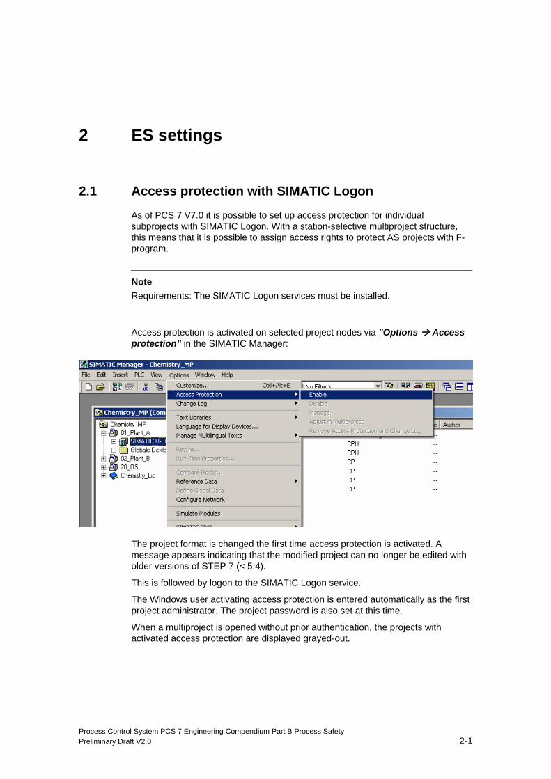
Access protection is activated on selected project nodes via "Options Access protection" in the SIMATIC Manager:
The project format is changed the first time access protection is activated. A message appears indicating that the modified project can no longer be edited with older versions of STEP 7 (< 5.4).
This is followed by logon to the SIMATIC Logon service.
The Windows user activating access protection is entered automatically as the first project administrator. The project password is also set at this time.
When a multiproject is opened without prior authentication, the projects with activated access protection are displayed grayed-out.
ES settings
Process Control System PCS 7 Engineering Compendium Part B Process Safety 2-2 Preliminary Draft V2.0
If you have not set access protection to restrict access to the ES to those persons authorized to modify safety programs, you will need to take the following organizational actions in the ES to ensure effective password protection:
• Only authorized persons are permitted to have access to the password.
• Before exiting the ES, authorized persons must expressly reset access authorization for the F-CPU (CPU > Access authorization > Cancel or close all applications in the SIMATIC Manager).
If you do not implement this procedure, you will also need to use a screen saver and only give the password for it to authorized persons.
2.2 Compiling
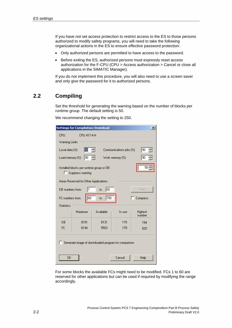
Set the threshold for generating the warning based on the number of blocks per runtime group. The default setting is 50.
We recommend changing the setting to 250.
For some blocks the available FCs might need to be modified. FCs 1 to 60 are reserved for other applications but can be used if required by modifying the range accordingly.
Process Control System PCS 7 Engineering Compendium Part B Process Safety Preliminary Draft V2.0 3-1
3 S7F/FH hardware parameterization
If you are using F-systems in conjunction with PCS 7, you will need the following CPUs: 412H, 414H and 417H.
3.1 CPU parameters (single F-system)
3.1.1 Password and access protection
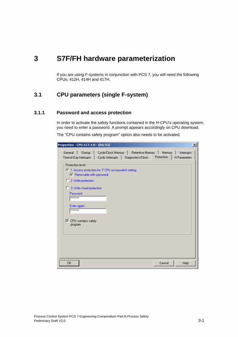
In order to activate the safety functions contained in the H-CPU's operating system, you need to enter a password. A prompt appears accordingly on CPU download.
The "CPU contains safety program" option also needs to be activated.
S7F/FH hardware parameterization
Process Control System PCS 7 Engineering Compendium Part B Process Safety 3-2 Preliminary Draft V2.0
Note Protection level 1 needs to be configured so that the prompt to enter the F-CPU password does not appear in the event of changes to the standard user program.
A password is also assigned to the fail-safe program; this is set the first time the user program is compiled. This password must not be the same as the CPU password.
3.1.2 Diagnostics/Clock
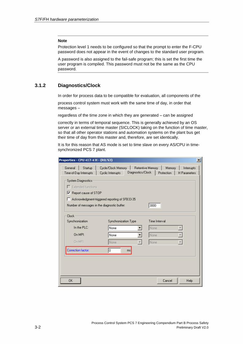
In order for process data to be compatible for evaluation, all components of the
process control system must work with the same time of day, in order that messages –
regardless of the time zone in which they are generated – can be assigned
correctly in terms of temporal sequence. This is generally achieved by an OS server or an external time master (SICLOCK) taking on the function of time master, so that all other operator stations and automation systems on the plant bus get their time of day from this master and, therefore, are set identically.
It is for this reason that AS mode is set to time slave on every AS/CPU in time-synchronized PCS 7 plant.
S7F/FH hardware parameterization
Process Control System PCS 7 Engineering Compendium Part B Process Safety Preliminary Draft V2.0 3-3
Check that the correction factor is set to 0 ms under "Time" on the "Diagnostics/Clock" tab.
3.1.3 Memory
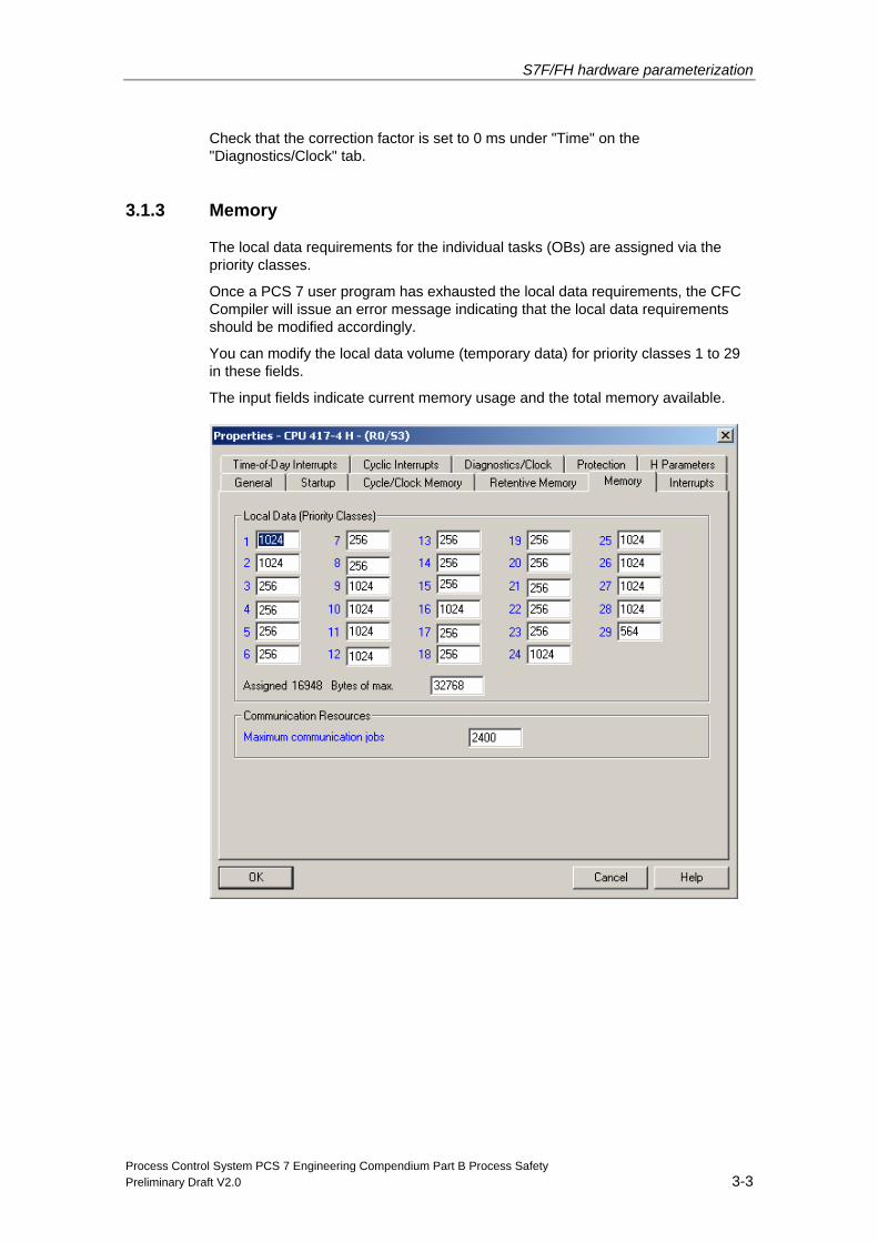
The local data requirements for the individual tasks (OBs) are assigned via the priority classes.
Once a PCS 7 user program has exhausted the local data requirements, the CFC Compiler will issue an error message indicating that the local data requirements should be modified accordingly.
You can modify the local data volume (temporary data) for priority classes 1 to 29 in these fields.
The input fields indicate current memory usage and the total memory available.
S7F/FH hardware parameterization
Process Control System PCS 7 Engineering Compendium Part B Process Safety 3-4 Preliminary Draft V2.0
3.2 CPU parameters (fault-tolerant F-system)
All settings made in the single F-system must also be made in the fault-tolerant system.
Note
Parameters in blue can be changed during active operation on an H-station.
3.2.1 Cyclic interrupts
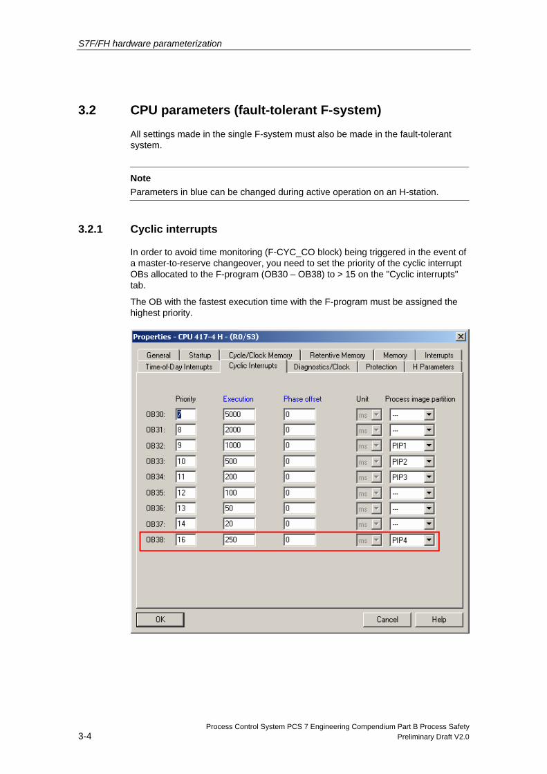
In order to avoid time monitoring (F-CYC_CO block) being triggered in the event of a master-to-reserve changeover, you need to set the priority of the cyclic interrupt OBs allocated to the F-program (OB30 – OB38) to > 15 on the "Cyclic interrupts" tab.
The OB with the fastest execution time with the F-program must be assigned the highest priority.
S7F/FH hardware parameterization
Process Control System PCS 7 Engineering Compendium Part B Process Safety Preliminary Draft V2.0 3-5
In the above example, the F-program is located in OB 38. Accordingly, the priority is set to 16 and the cycle time is set in accordance with the required sampling rate (in this case 250ms).
Process image partitions do not need to be configured for F-program parts. In S7 F/FH systems, F-driver blocks, rather than the process image, are used to access the F-I/O.
3.2.2 H parameters
The following settings must be made when using redundant CPUs.
Furthermore, the F-program's cyclic interrupt OB has to be configured as a "cyclic interrupt OB with special treatment".
Self-test (advanced CPU test) During the self-test, the master and reserve CPUs compare memory content. If the test reveals that the content of the two memories does not match, a comparison error will be reported.
Test cycle time The test cycle time (default 90 minutes) indicates the time taken for a complete background self-test.
Note
For S7 FH systems, this parameter can be increased up to a maximum of 12 hours (720 minutes).
Times in excess of 720 minutes will trigger an F-STOP. In such cases, the following diagnostics event will be written to the F-CPU's diagnostics buffer:
"Safety program: Error detected" (event ID 16#75E1)
Response to RAM/PAA error ERROR-SEARCH mode is set by default in response to a comparison error (default response). The purpose of error-search mode is to detect and identify a faulty CPU.
Select how the H-system should respond to an error generated during the comparison of the RAM areas and the process images of the outputs:
• ERROR-SEARCH
• Stop of the H-system: The entire H-system is set to stop status.
• STOP of reserve: The reserve CPU is set to STOP mode, the master CPU remains in RUN (solo mode system status).
S7F/FH hardware parameterization
Process Control System PCS 7 Engineering Compendium Part B Process Safety 3-6 Preliminary Draft V2.0
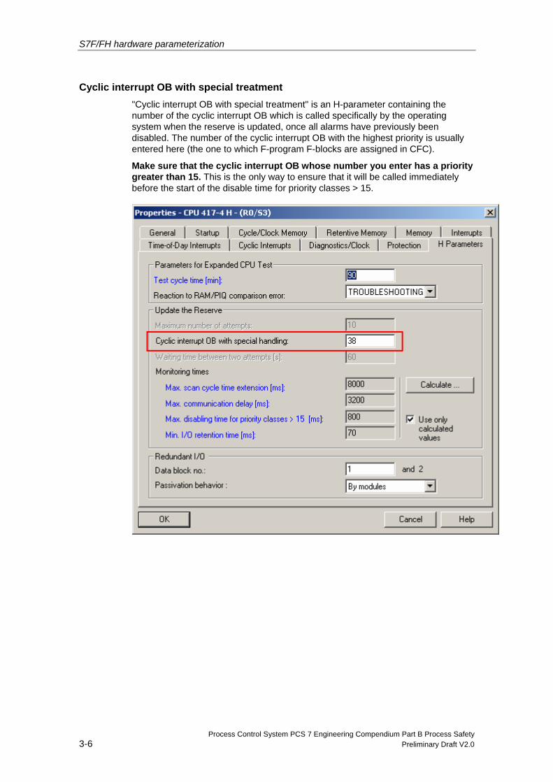
Cyclic interrupt OB with special treatment "Cyclic interrupt OB with special treatment" is an H-parameter containing the number of the cyclic interrupt OB which is called specifically by the operating system when the reserve is updated, once all alarms have previously been disabled. The number of the cyclic interrupt OB with the highest priority is usually entered here (the one to which F-program F-blocks are assigned in CFC).
Make sure that the cyclic interrupt OB whose number you enter has a priority greater than 15. This is the only way to ensure that it will be called immediately before the start of the disable time for priority classes > 15.
S7F/FH hardware parameterization
Process Control System PCS 7 Engineering Compendium Part B Process Safety Preliminary Draft V2.0 3-7
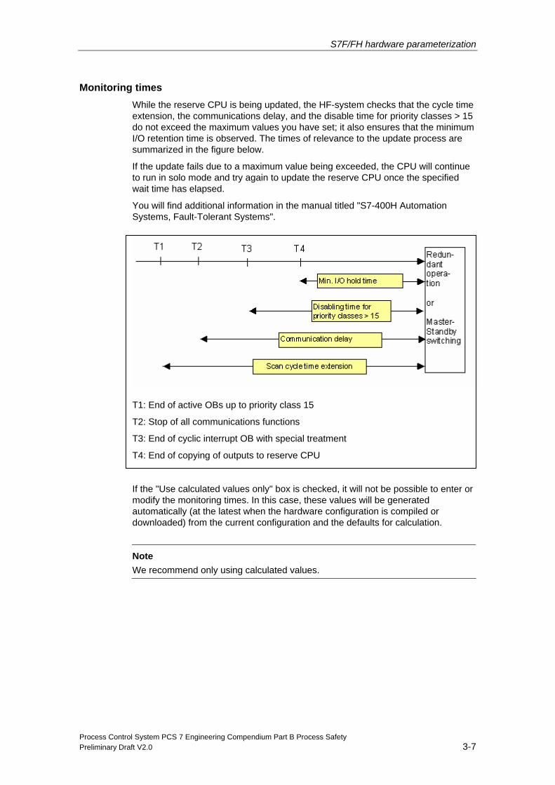
Monitoring times While the reserve CPU is being updated, the HF-system checks that the cycle time extension, the communications delay, and the disable time for priority classes > 15 do not exceed the maximum values you have set; it also ensures that the minimum I/O retention time is observed. The times of relevance to the update process are summarized in the figure below.
If the update fails due to a maximum value being exceeded, the CPU will continue to run in solo mode and try again to update the reserve CPU once the specified wait time has elapsed.
You will find additional information in the manual titled "S7-400H Automation Systems, Fault-Tolerant Systems".
T1: End of active OBs up to priority class 15
T2: Stop of all communications functions
T3: End of cyclic interrupt OB with special treatment
T4: End of copying of outputs to reserve CPU
If the "Use calculated values only" box is checked, it will not be possible to enter or modify the monitoring times. In this case, these values will be generated automatically (at the latest when the hardware configuration is compiled or downloaded) from the current configuration and the defaults for calculation.
Note
We recommend only using calculated values.
S7F/FH hardware parameterization
Process Control System PCS 7 Engineering Compendium Part B Process Safety 3-8 Preliminary Draft V2.0
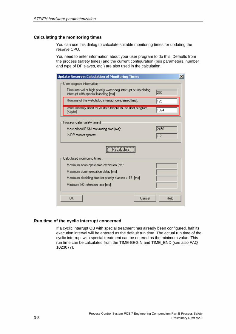
Calculating the monitoring times You can use this dialog to calculate suitable monitoring times for updating the reserve CPU.
You need to enter information about your user program to do this. Defaults from the process (safety times) and the current configuration (bus parameters, number and type of DP slaves, etc.) are also used in the calculation.
Run time of the cyclic interrupt concerned If a cyclic interrupt OB with special treatment has already been configured, half its execution interval will be entered as the default run time. The actual run time of the cyclic interrupt with special treatment can be entered as the minimum value. This run time can be calculated from the TIME-BEGIN and TIME_END (see also FAQ 1023077).
S7F/FH hardware parameterization
Process Control System PCS 7 Engineering Compendium Part B Process Safety Preliminary Draft V2.0 3-9
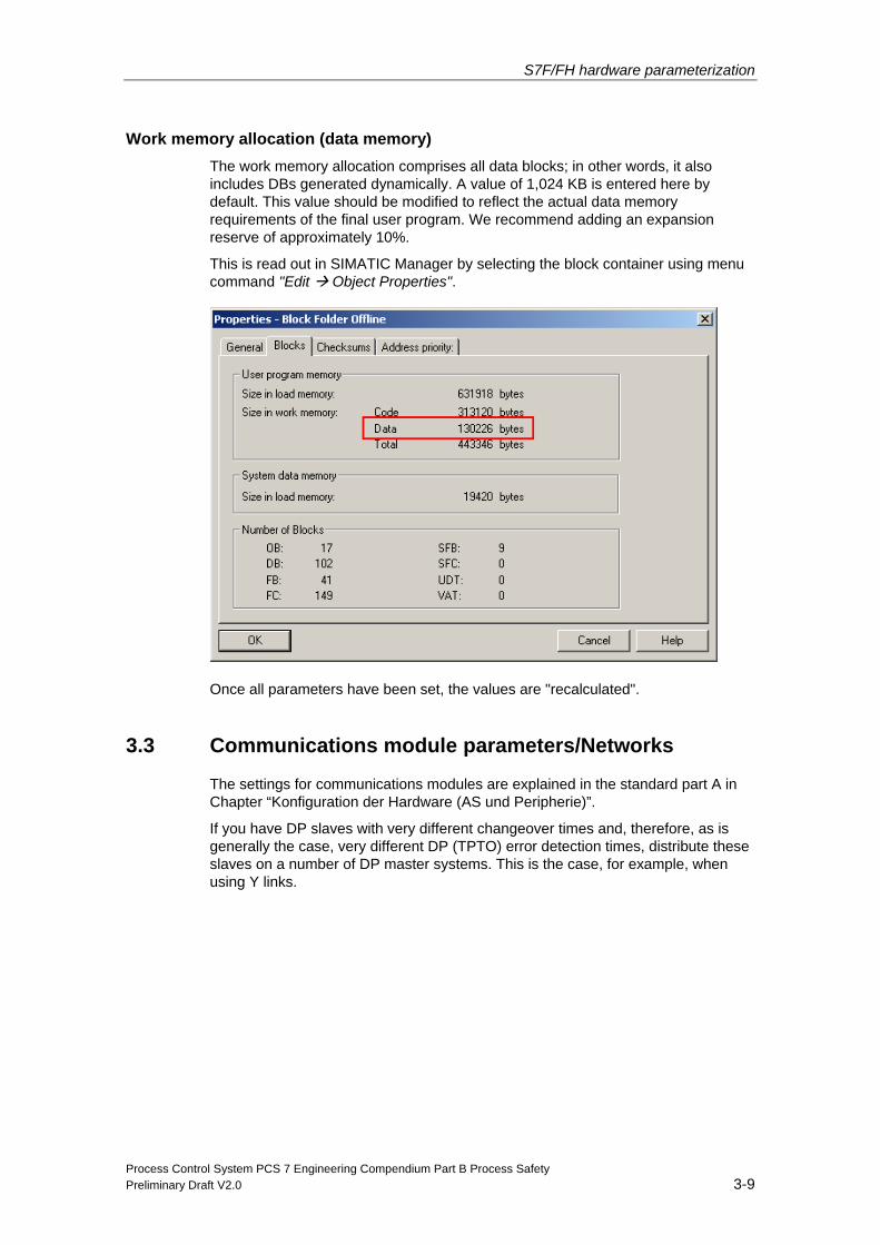
Work memory allocation (data memory) The work memory allocation comprises all data blocks; in other words, it also includes DBs generated dynamically. A value of 1,024 KB is entered here by default. This value should be modified to reflect the actual data memory requirements of the final user program. We recommend adding an expansion reserve of approximately 10%.
This is read out in SIMATIC Manager by selecting the block container using menu command "Edit Object Properties".
Once all parameters have been set, the values are "recalculated".
3.3 Communications module parameters/Networks
The settings for communications modules are explained in the standard part A in Chapter “Konfiguration der Hardware (AS und Peripherie)”.
If you have DP slaves with very different changeover times and, therefore, as is generally the case, very different DP (TPTO) error detection times, distribute these slaves on a number of DP master systems. This is the case, for example, when using Y links.
S7F/FH hardware parameterization
Process Control System PCS 7 Engineering Compendium Part B Process Safety 3-10 Preliminary Draft V2.0
3.4 I/O module system parameters
Like standard modules, F-modules are always configured in accordance with the same model:
Once you have added the F-I/O in the HW Config station window, you can access the configuration dialog by selecting the menu command Edit > Object Properties or double-clicking the corresponding F-I/O module.
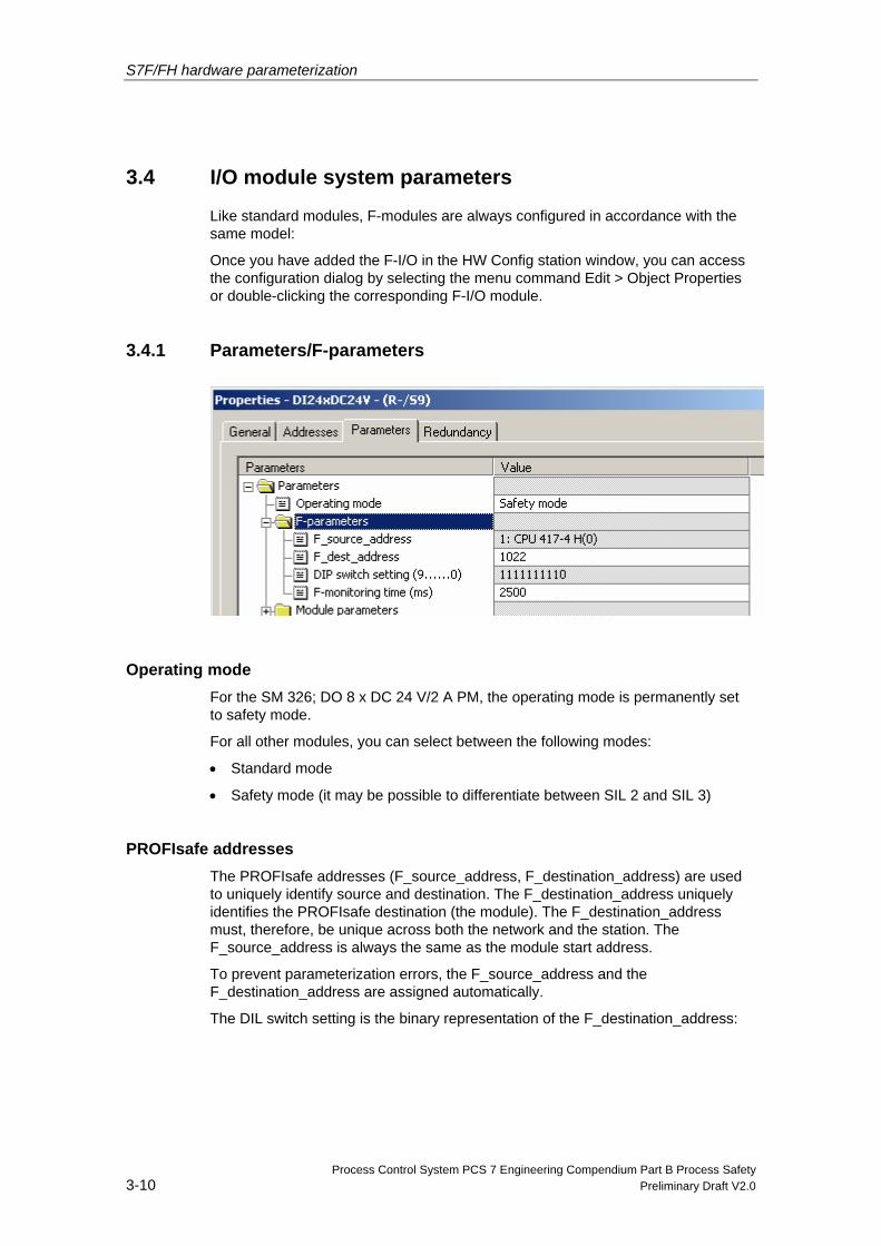
3.4.1 Parameters/F-parameters
Operating mode For the SM 326; DO 8 x DC 24 V/2 A PM, the operating mode is permanently set to safety mode.
For all other modules, you can select between the following modes:
• Standard mode
• Safety mode (it may be possible to differentiate between SIL 2 and SIL 3)
PROFIsafe addresses The PROFIsafe addresses (F_source_address, F_destination_address) are used to uniquely identify source and destination. The F_destination_address uniquely identifies the PROFIsafe destination (the module). The F_destination_address must, therefore, be unique across both the network and the station. The F_source_address is always the same as the module start address.
To prevent parameterization errors, the F_source_address and the F_destination_address are assigned automatically.
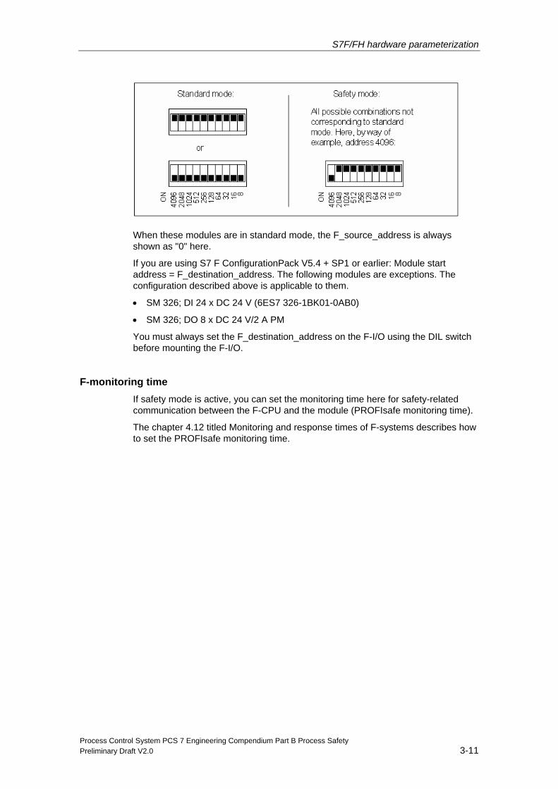
The DIL switch setting is the binary representation of the F_destination_address:
S7F/FH hardware parameterization
Process Control System PCS 7 Engineering Compendium Part B Process Safety Preliminary Draft V2.0 3-11
When these modules are in standard mode, the F_source_address is always shown as "0" here.
If you are using S7 F ConfigurationPack V5.4 + SP1 or earlier: Module start address = F_destination_address. The following modules are exceptions. The configuration described above is applicable to them.
• SM 326; DI 24 x DC 24 V (6ES7 326-1BK01-0AB0)
• SM 326; DO 8 x DC 24 V/2 A PM
You must always set the F_destination_address on the F-I/O using the DIL switch before mounting the F-I/O.
F-monitoring time If safety mode is active, you can set the monitoring time here for safety-related communication between the F-CPU and the module (PROFIsafe monitoring time).
The chapter 4.12 titled Monitoring and response times of F-systems describes how to set the PROFIsafe monitoring time.
S7F/FH hardware parameterization
Process Control System PCS 7 Engineering Compendium Part B Process Safety 3-12 Preliminary Draft V2.0
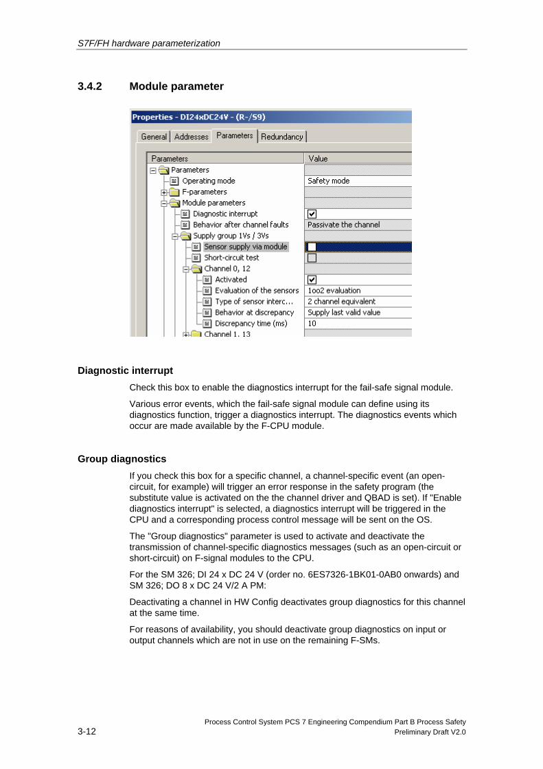
3.4.2 Module parameter
Diagnostic interrupt Check this box to enable the diagnostics interrupt for the fail-safe signal module.
Various error events, which the fail-safe signal module can define using its diagnostics function, trigger a diagnostics interrupt. The diagnostics events which occur are made available by the F-CPU module.
Group diagnostics If you check this box for a specific channel, a channel-specific event (an open-circuit, for example) will trigger an error response in the safety program (the substitute value is activated on the the channel driver and QBAD is set). If "Enable diagnostics interrupt" is selected, a diagnostics interrupt will be triggered in the CPU and a corresponding process control message will be sent on the OS.
The "Group diagnostics" parameter is used to activate and deactivate the transmission of channel-specific diagnostics messages (such as an open-circuit or short-circuit) on F-signal modules to the CPU.
For the SM 326; DI 24 x DC 24 V (order no. 6ES7326-1BK01-0AB0 onwards) and SM 326; DO 8 x DC 24 V/2 A PM:
Deactivating a channel in HW Config deactivates group diagnostics for this channel at the same time.
For reasons of availability, you should deactivate group diagnostics on input or output channels which are not in use on the remaining F-SMs.
S7F/FH hardware parameterization
Process Control System PCS 7 Engineering Compendium Part B Process Safety Preliminary Draft V2.0 3-13
Note Where fail-safe input and output modules in safety mode are concerned, group diagnostics must be active on all connected channels. Please check that group diagnostics has only been deactivated for input and output channels which are not in use. The diagnostics interrupt (OB82 call) can be deactivated as an option; it is not required from a safety-related point of view.
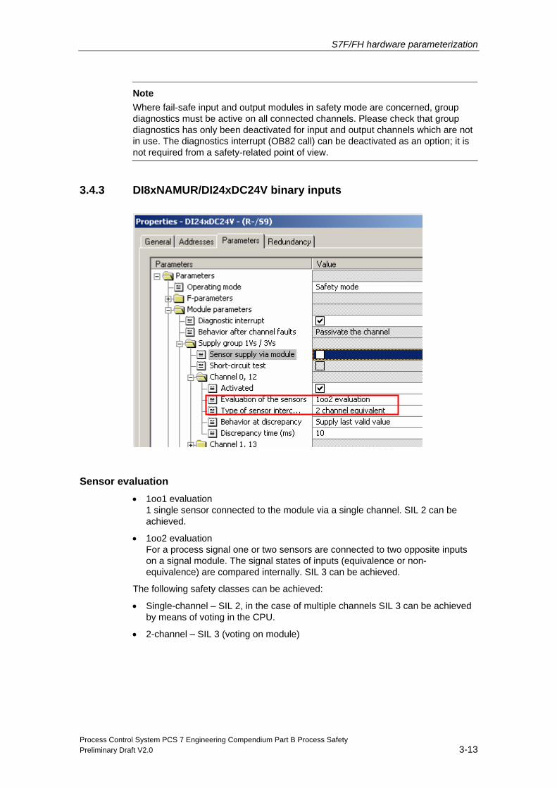
3.4.3 DI8xNAMUR/DI24xDC24V binary inputs
Sensor evaluation • 1oo1 evaluation
1 single sensor connected to the module via a single channel. SIL 2 can be achieved.
• 1oo2 evaluation For a process signal one or two sensors are connected to two opposite inputs on a signal module. The signal states of inputs (equivalence or non-equivalence) are compared internally. SIL 3 can be achieved.
The following safety classes can be achieved:
• Single-channel – SIL 2, in the case of multiple channels SIL 3 can be achieved by means of voting in the CPU.
• 2-channel – SIL 3 (voting on module)
S7F/FH hardware parameterization
Process Control System PCS 7 Engineering Compendium Part B Process Safety 3-14 Preliminary Draft V2.0
Examples see the Manual "Wiring and Voting Architectures for ET200M F AI”:
http://support.automation.siemens.com/WW/view/en/24690377
Sensor supply via module You can set whether the sensor is supplied via the module here. If it is, you can also activate a short-circuit test for this supply. Whenever a short-circuit is detected, the module will trigger a diagnostics interrupt on the CPU and send a corresponding process control message to the OS.
Short-circuit test You can use this parameter to activate short-circuit detection for the fail-safe S7-300 signal module.
We only recommend implementing short-circuit testing if you are using simple switches which do not have a separate power supply. In this case you should use the fail-safe signal module's sensor supply.
Short-circuit detection disconnects the sensor supply briefly. A cross-circuit is detected at the active inputs (L+ fault).
Type of sensor interconnection If 1oo2 sensor evaluation is selected, you can select the type of sensor interconnection for each input channel here (exception: this parameter does not exist for the SM 326; DI 8 x Namur. For this module, where "1oo2 evaluation" is concerned, only 2-channel equivalent sensor interconnection can generally be selected.):
• "2-channel equivalent": Connect one two-channel sensor or two single-channel sensors (2-channel connection) to two opposite input channels.
• "2-channel non-equivalent": Connect one non-equivalent sensor or two single-channel sensors (2-channel non-equivalent) to two opposite input channels.
• "Single-channel": Connect one sensor (single-channel) to two opposite inputs.
Discrepancy time Where "1oo1 evaluation" is concerned, the displayed value is not relevant.
The discrepancy analysis for equivalence/non-equivalence is used for fail-safe inputs in order to detect errors from the temporal characteristic of two signals with identical functionality. The discrepancy analysis is started whenever different levels (when testing for non-equivalence: the same level) are detected on two associated input signals. A test is run to see whether, once a configurable period of time known as the discrepancy time has elapsed, the difference (when testing for non-equivalence: the match) disappears. If not, there is a discrepancy error.
S7F/FH hardware parameterization
Process Control System PCS 7 Engineering Compendium Part B Process Safety Preliminary Draft V2.0 3-15
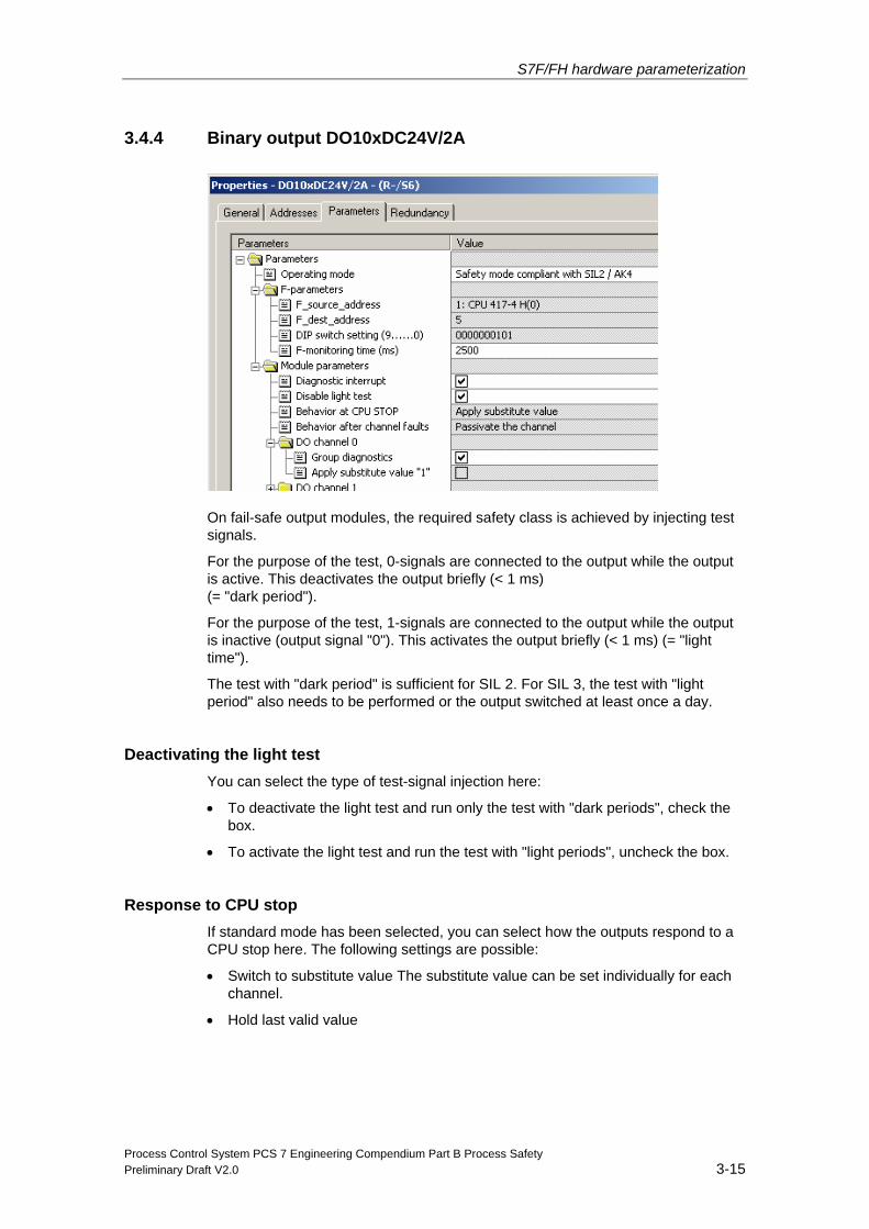
3.4.4 Binary output DO10xDC24V/2A
On fail-safe output modules, the required safety class is achieved by injecting test signals.
For the purpose of the test, 0-signals are connected to the output while the output is active. This deactivates the output briefly (< 1 ms) (= "dark period").
For the purpose of the test, 1-signals are connected to the output while the output is inactive (output signal "0"). This activates the output briefly (< 1 ms) (= "light time").
The test with "dark period" is sufficient for SIL 2. For SIL 3, the test with "light period" also needs to be performed or the output switched at least once a day.
Deactivating the light test You can select the type of test-signal injection here:
• To deactivate the light test and run only the test with "dark periods", check the box.
• To activate the light test and run the test with "light periods", uncheck the box.
Response to CPU stop If standard mode has been selected, you can select how the outputs respond to a CPU stop here. The following settings are possible:
• Switch to substitute value The substitute value can be set individually for each channel.
• Hold last valid value
S7F/FH hardware parameterization
Process Control System PCS 7 Engineering Compendium Part B Process Safety 3-16 Preliminary Draft V2.0
If safety mode has been selected, in the event of a CPU stop, the substitute value "0" will be output at all outputs.
Response following channel errors You can use this parameter to define, for the module's safety mode, whether the entire module or just the fault channel(s) is (are) passivated in the event of channel errors:
• "Passivate entire module"
• "Passivate channel"
The setting of this parameter will only be relevant if you run the module in "safety mode" with S7 Distributed Safety V 5.4 or higher.
Switching to substitute value "1" in standard mode If standard mode is set and "Switch to substitute value" has been selected, for each channel, you can select which substitute value the module should output in the event of a CPU stop here:
• To output substitute value "0", uncheck the box.
• To output substitute value "1", check the box.
If safety mode has been selected, in the event of a CPU stop, the substitute value "0" will be output at all outputs.
S7F/FH hardware parameterization
Process Control System PCS 7 Engineering Compendium Part B Process Safety Preliminary Draft V2.0 3-17
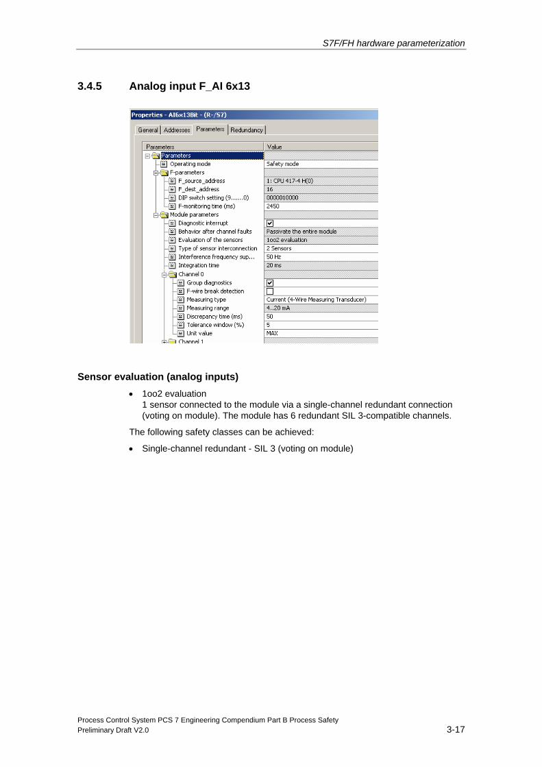
3.4.5 Analog input F_AI 6x13
Sensor evaluation (analog inputs) • 1oo2 evaluation
1 sensor connected to the module via a single-channel redundant connection (voting on module). The module has 6 redundant SIL 3-compatible channels.
The following safety classes can be achieved:
• Single-channel redundant - SIL 3 (voting on module)
S7F/FH hardware parameterization
Process Control System PCS 7 Engineering Compendium Part B Process Safety 3-18 Preliminary Draft V2.0
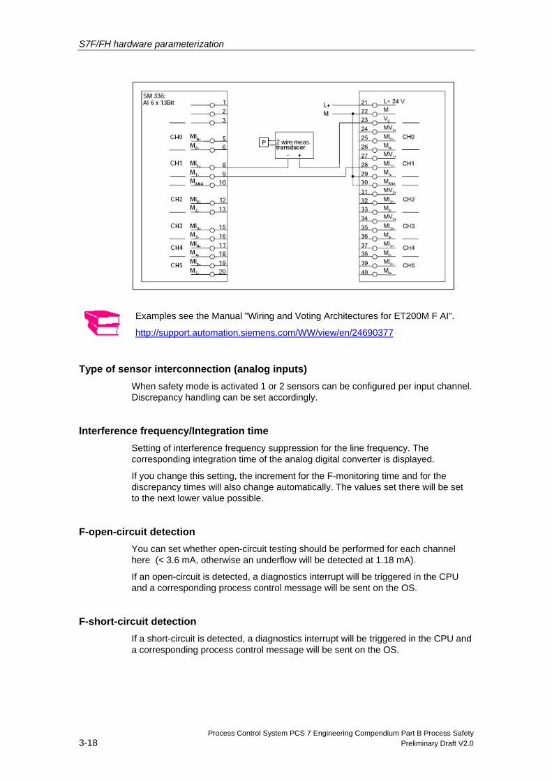
Examples see the Manual "Wiring and Voting Architectures for ET200M F AI”.
http://support.automation.siemens.com/WW/view/en/24690377
Type of sensor interconnection (analog inputs) When safety mode is activated 1 or 2 sensors can be configured per input channel. Discrepancy handling can be set accordingly.
Interference frequency/Integration time Setting of interference frequency suppression for the line frequency. The corresponding integration time of the analog digital converter is displayed.
If you change this setting, the increment for the F-monitoring time and for the discrepancy times will also change automatically. The values set there will be set to the next lower value possible.
F-open-circuit detection You can set whether open-circuit testing should be performed for each channel here (< 3.6 mA, otherwise an underflow will be detected at 1.18 mA).
If an open-circuit is detected, a diagnostics interrupt will be triggered in the CPU and a corresponding process control message will be sent on the OS.
F-short-circuit detection If a short-circuit is detected, a diagnostics interrupt will be triggered in the CPU and a corresponding process control message will be sent on the OS.
S7F/FH hardware parameterization
Process Control System PCS 7 Engineering Compendium Part B Process Safety Preliminary Draft V2.0 3-19
Advanced short-circuit diagnostics can be triggered when required by means of additional limit-value monitoring. For more information, see the block description of the channel driver block (F_CH_AI).
Measurement type You can select the measurement type for a channel or deactivate a channel (both on a channel-specific basis) here.
• "U" for voltage measurements (only possible for channels 0 to 3 and in standard mode)
• "2WMC" or "4WMC" for current measurements (as appropriate for the transducer used).
• "Deactivated", in order not to take any measurements with a channel.
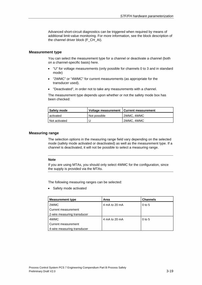
The measurement type depends upon whether or not the safety mode box has been checked:
Safety mode Voltage measurement Current measurement
activated Not possible 2WMC, 4WMC Not activated U 2WMC, 4WMC
Measuring range The selection options in the measuring range field vary depending on the selected mode (safety mode activated or deactivated) as well as the measurement type. If a channel is deactivated, it will not be possible to select a measuring range.
Note
If you are using MTAs, you should only select 4WMC for the configuration, since the supply is provided via the MTAs.
The following measuring ranges can be selected:
• Safety mode activated
Measurement type Area Channels
2WMC Current measurement 2-wire measuring transducer
4 mA to 20 mA 0 to 5
4WMC Current measurement 4-wire measuring transducer
4 mA to 20 mA 0 to 5
S7F/FH hardware parameterization
Process Control System PCS 7 Engineering Compendium Part B Process Safety 3-20 Preliminary Draft V2.0
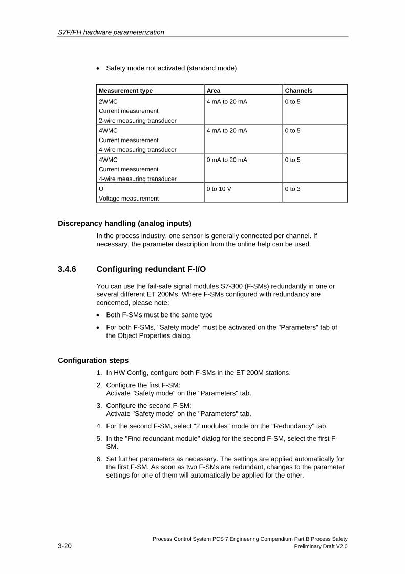
• Safety mode not activated (standard mode)
Measurement type Area Channels
2WMC Current measurement 2-wire measuring transducer
4 mA to 20 mA 0 to 5
4WMC Current measurement 4-wire measuring transducer
4 mA to 20 mA 0 to 5
4WMC Current measurement 4-wire measuring transducer
0 mA to 20 mA 0 to 5
U Voltage measurement
0 to 10 V 0 to 3
Discrepancy handling (analog inputs) In the process industry, one sensor is generally connected per channel. If necessary, the parameter description from the online help can be used.
3.4.6 Configuring redundant F-I/O
You can use the fail-safe signal modules S7-300 (F-SMs) redundantly in one or several different ET 200Ms. Where F-SMs configured with redundancy are concerned, please note:
• Both F-SMs must be the same type
• For both F-SMs, "Safety mode" must be activated on the "Parameters" tab of the Object Properties dialog.
Configuration steps 1. In HW Config, configure both F-SMs in the ET 200M stations.
2. Configure the first F-SM: Activate "Safety mode" on the "Parameters" tab.
3. Configure the second F-SM: Activate "Safety mode" on the "Parameters" tab.
4. For the second F-SM, select "2 modules" mode on the "Redundancy" tab.
5. In the "Find redundant module" dialog for the second F-SM, select the first F-SM.
6. Set further parameters as necessary. The settings are applied automatically for the first F-SM. As soon as two F-SMs are redundant, changes to the parameter settings for one of them will automatically be applied for the other.
S7F/FH hardware parameterization
Process Control System PCS 7 Engineering Compendium Part B Process Safety Preliminary Draft V2.0 3-21
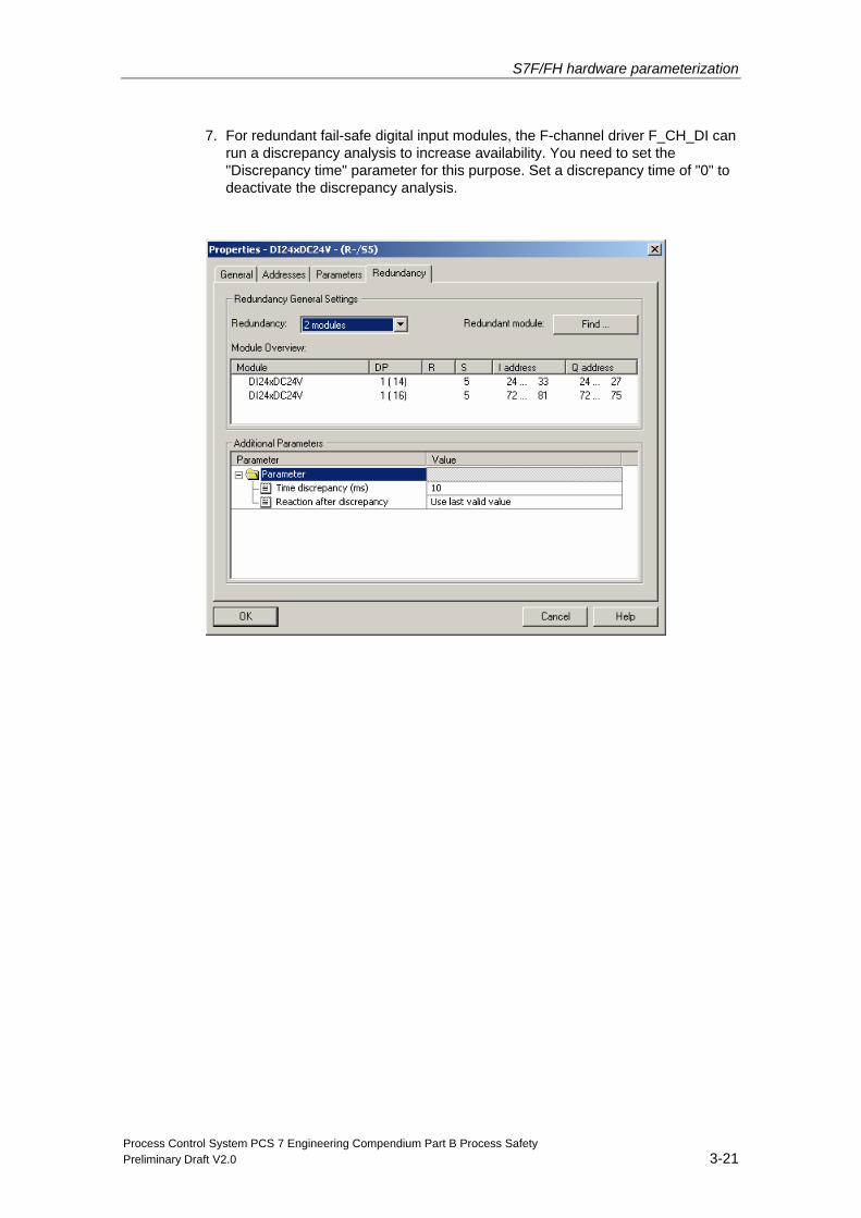
7. For redundant fail-safe digital input modules, the F-channel driver F_CH_DI can run a discrepancy analysis to increase availability. You need to set the "Discrepancy time" parameter for this purpose. Set a discrepancy time of "0" to deactivate the discrepancy analysis.
S7F/FH hardware parameterization
Process Control System PCS 7 Engineering Compendium Part B Process Safety 3-22 Preliminary Draft V2.0
3.4.7 Terminal Modules (MTAs)
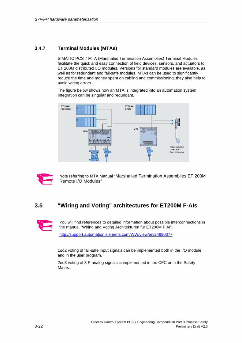
SIMATIC PCS 7 MTA (Marshaled Termination Assemblies) Terminal Modules facilitate the quick and easy connection of field devices, sensors, and actuators to ET 200M distributed I/O modules. Versions for standard modules are available, as well as for redundant and fail-safe modules. MTAs can be used to significantly reduce the time and money spent on cabling and commissioning; they also help to avoid wiring errors.
The figure below shows how an MTA is integrated into an automation system. Integration can be singular and redundant.
Note referring to MTA Manual “Marshalled Termination Assemblies ET 200M Remote I/O Modules”
3.5 "Wiring and Voting" architectures for ET200M F-AIs
You will find references to detailed information about possible interconnections in the manual "Wiring and Voting Architekturen für ET200M F AI”.
http://support.automation.siemens.com/WW/view/en/24690377
1oo2 voting of fail-safe input signals can be implemented both in the I/O module and in the user program.
2oo3 voting of 3 F-analog signals is implemented in the CFC or in the Safety Matrix.
S7F/FH hardware parameterization
Process Control System PCS 7 Engineering Compendium Part B Process Safety Preliminary Draft V2.0 3-23
3.5.1 Voting with F-DI
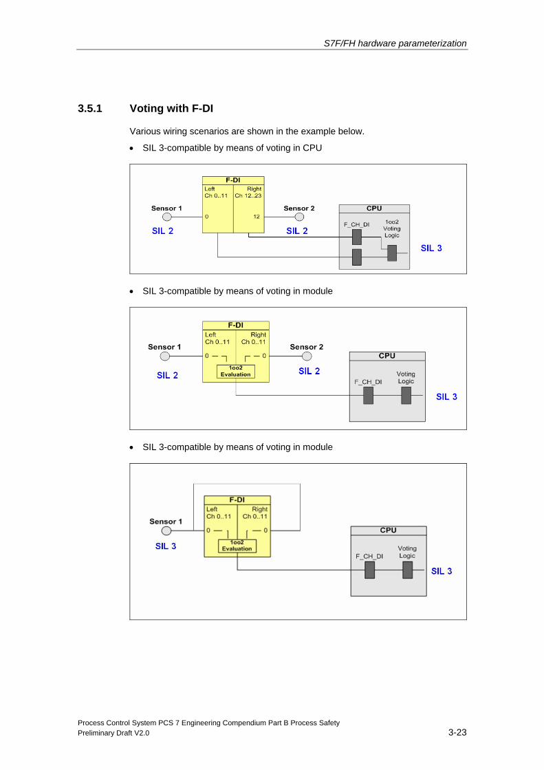
Various wiring scenarios are shown in the example below.
• SIL 3-compatible by means of voting in CPU
• SIL 3-compatible by means of voting in module
• SIL 3-compatible by means of voting in module
S7F/FH hardware parameterization
Process Control System PCS 7 Engineering Compendium Part B Process Safety 3-24 Preliminary Draft V2.0
3.5.2 Voting with F-AI
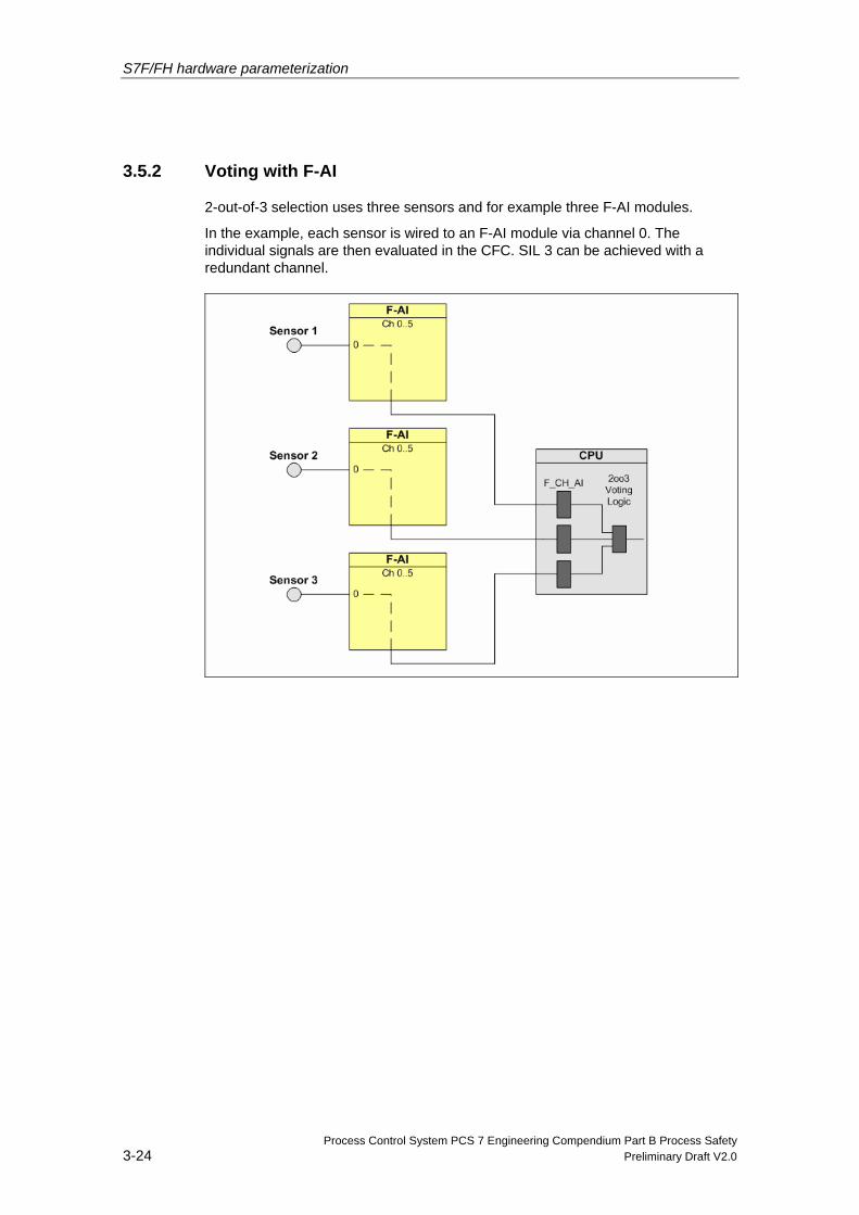
2-out-of-3 selection uses three sensors and for example three F-AI modules.
In the example, each sensor is wired to an F-AI module via channel 0. The individual signals are then evaluated in the CFC. SIL 3 can be achieved with a redundant channel.
Process Control System PCS 7 Engineering Compendium Part B Process Safety Preliminary Draft V2.0 4-1
4 Configuring the safety program
4.1 Fail-safe application program
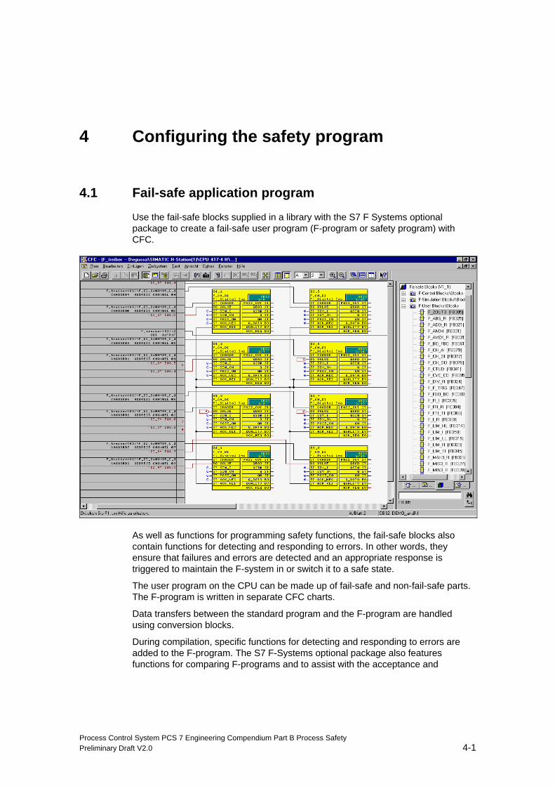
Use the fail-safe blocks supplied in a library with the S7 F Systems optional package to create a fail-safe user program (F-program or safety program) with CFC.
As well as functions for programming safety functions, the fail-safe blocks also contain functions for detecting and responding to errors. In other words, they ensure that failures and errors are detected and an appropriate response is triggered to maintain the F-system in or switch it to a safe state.
The user program on the CPU can be made up of fail-safe and non-fail-safe parts. The F-program is written in separate CFC charts.
Data transfers between the standard program and the F-program are handled using conversion blocks.
During compilation, specific functions for detecting and responding to errors are added to the F-program. The S7 F-Systems optional package also features functions for comparing F-programs and to assist with the acceptance and
Configuring the safety program
Process Control System PCS 7 Engineering Compendium Part B Process Safety 4-2 Preliminary Draft V2.0
approval procedure for F-programs, for example functions to generate a reference sum via the F-program which can be used to detect even the most minor of changes. This reference sum is recorded as part of the TÜV acceptance and approval procedure.
4.2 Program structure of the safety program
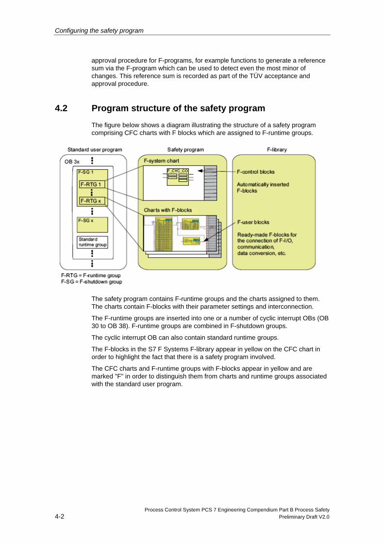
The figure below shows a diagram illustrating the structure of a safety program comprising CFC charts with F blocks which are assigned to F-runtime groups.
The safety program contains F-runtime groups and the charts assigned to them. The charts contain F-blocks with their parameter settings and interconnection.
The F-runtime groups are inserted into one or a number of cyclic interrupt OBs (OB 30 to OB 38). F-runtime groups are combined in F-shutdown groups.
The cyclic interrupt OB can also contain standard runtime groups.
The F-blocks in the S7 F Systems F-library appear in yellow on the CFC chart in order to highlight the fact that there is a safety program involved.
The CFC charts and F-runtime groups with F-blocks appear in yellow and are marked "F" in order to distinguish them from charts and runtime groups associated with the standard user program.
Configuring the safety program
Process Control System PCS 7 Engineering Compendium Part B Process Safety Preliminary Draft V2.0 4-3
4.3 Creating the safety program
4.3.1 Requirements
• You must have created a project structure in the SIMATIC Manager.
• Prior to programming, you must have previously configured the hardware components of your project, in particular the F-CPU and the F-I/O, for safety mode.
• You must have assigned your safety program to an F-compatible CPU such as a CPU 412-3H, CPU 414-4H or CPU 417-4H.
4.3.2 Defining the program structure
In addition to considering the standard scenario, you need to answer the following questions when drafting a safety program:
• Which parts of the S7 program need to be fail-safe?
• What are the response times you wish to achieve?
You will then need to split your F-program into various OB 3x instances
accordingly.
You will improve performance if you program parts of the program which are not needed for the safety functions in the standard user program.
In respect of the division of your program between the standard user program and the safety program, please remember that the standard user program is easier to change and download to the F-CPU. Changes to the standard user program do not usually need to undergo acceptance and approval.
Rules governing program structure When drafting a safety program for S7 F/FH Systems, you need to observe the following rules:
• F-runtime groups with F-blocks can only be assigned to cyclic interrupts OB 30 to OB 38.
• A chart can contain both F-blocks and standard blocks. You are not permitted to use these charts as F-block types.
• In the safety program, access to the F-I/O blocks is only permitted via the F-channel driver (F_CH_xx).
Configuring the safety program
Process Control System PCS 7 Engineering Compendium Part B Process Safety 4-4 Preliminary Draft V2.0
4.3.3 Library
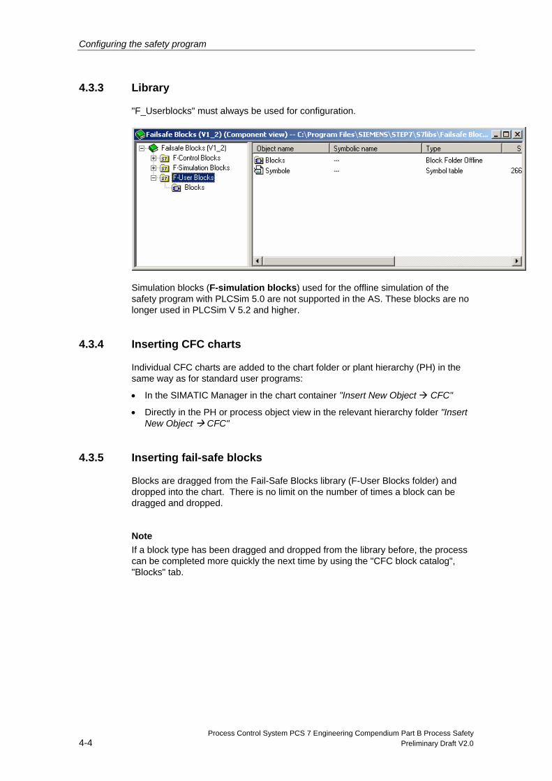
"F_Userblocks" must always be used for configuration.
Simulation blocks (F-simulation blocks) used for the offline simulation of the safety program with PLCSim 5.0 are not supported in the AS. These blocks are no longer used in PLCSim V 5.2 and higher.
4.3.4 Inserting CFC charts
Individual CFC charts are added to the chart folder or plant hierarchy (PH) in the same way as for standard user programs:
• In the SIMATIC Manager in the chart container "Insert New Object CFC"
• Directly in the PH or process object view in the relevant hierarchy folder "Insert New Object CFC"
4.3.5 Inserting fail-safe blocks
Blocks are dragged from the Fail-Safe Blocks library (F-User Blocks folder) and dropped into the chart. There is no limit on the number of times a block can be dragged and dropped.
Note
If a block type has been dragged and dropped from the library before, the process can be completed more quickly the next time by using the "CFC block catalog", "Blocks" tab.
Configuring the safety program
Process Control System PCS 7 Engineering Compendium Part B Process Safety Preliminary Draft V2.0 4-5
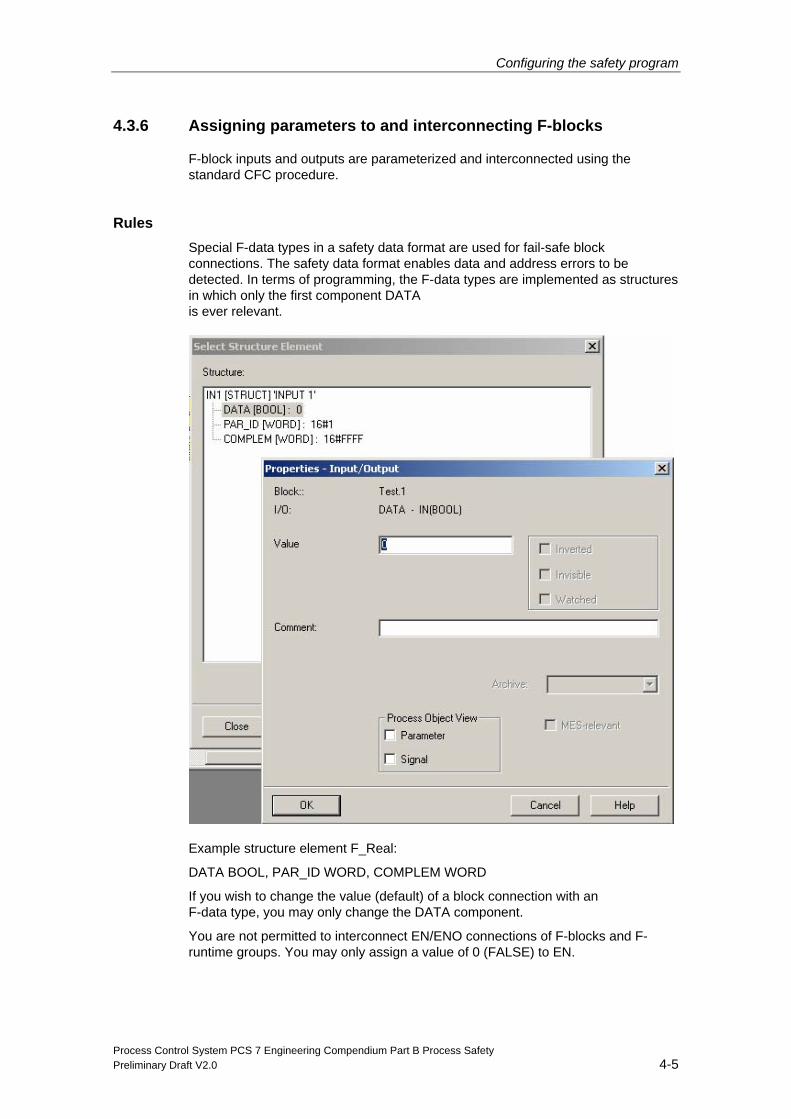
4.3.6 Assigning parameters to and interconnecting F-blocks
F-block inputs and outputs are parameterized and interconnected using the standard CFC procedure.
Rules Special F-data types in a safety data format are used for fail-safe block connections. The safety data format enables data and address errors to be detected. In terms of programming, the F-data types are implemented as structures in which only the first component DATA is ever relevant.
Example structure element F_Real:
DATA BOOL, PAR_ID WORD, COMPLEM WORD
If you wish to change the value (default) of a block connection with an F-data type, you may only change the DATA component.
You are not permitted to interconnect EN/ENO connections of F-blocks and F-runtime groups. You may only assign a value of 0 (FALSE) to EN.
Configuring the safety program
Process Control System PCS 7 Engineering Compendium Part B Process Safety 4-6 Preliminary Draft V2.0
Changes to the input parameters of F-blocks with F-data types can be made as follows:
• Offline with the assistance of the CFC editor
or
• Online using CFC test mode with safety mode deactivated
Note
Values of PAR_ID and COMPLEM must not be changed.
If errors in the safety data format are detected during the execution of the safety program, an F-STOP is triggered.
4.3.7 Run sequence of F-blocks
Defining the run sequence You define the run sequence in the CFC editor in the same way as for a standard user program. Changing the run sequence also changes the overall signature.
Correct run sequence of F-blocks The sequence of the F-blocks within the F-shutdown group is relevant. The number of F-runtime groups the F-shutdown group has been split into is of no relevance.
Essentially, the correct run sequence of the various F-block types is as follows:
1. Placed automatically:
- F-module driver for F-I/O with inputs or with inputs and outputs
- F-communications blocks and F-system blocks for receiving
- F-blocks for data conversion
2. F-channel drivers for inputs
3. F-blocks for user logic
4. F-channel drivers for outputs
5. Placed automatically:
- F-block F_PLK
- F-block F_PSG_M
- F-module driver for F-I/O with outputs or with inputs and outputs
- F-communications blocks and F-system blocks for sending
- F-block F_PLK_O
- F-block F_DIAG (as of F-Systems V6.0)
Configuring the safety program
Process Control System PCS 7 Engineering Compendium Part B Process Safety Preliminary Draft V2.0 4-7
The run sequence of the blocks listed under items 1 and 5 is adjusted automatically when the F-program is compiled.
The IPO principle (input, process, output) must always be observed when placing F-channel drivers and F-blocks for user logic. This will ensure that all inputs are read first, the relevant processing steps are then initiated, and the procedure comes to a close with the writing of all outputs.
Furthermore, F-monitoring blocks only visible following compilation are also added automatically.
Note
You are not permitted to change the run sequence of automatically inserted F-monitoring blocks. Neither can these blocks be deleted or changes made to them.
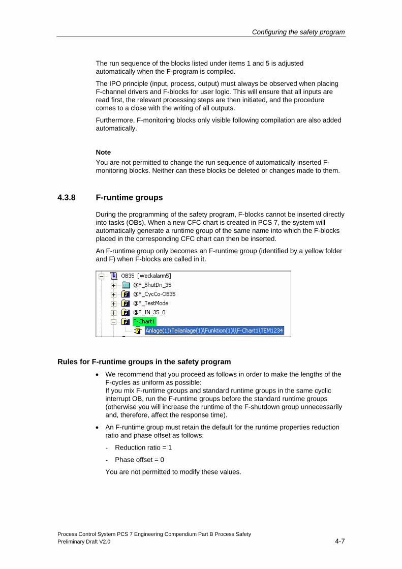
4.3.8 F-runtime groups
During the programming of the safety program, F-blocks cannot be inserted directly into tasks (OBs). When a new CFC chart is created in PCS 7, the system will automatically generate a runtime group of the same name into which the F-blocks placed in the corresponding CFC chart can then be inserted.
An F-runtime group only becomes an F-runtime group (identified by a yellow folder and F) when F-blocks are called in it.
Rules for F-runtime groups in the safety program • We recommend that you proceed as follows in order to make the lengths of the
F-cycles as uniform as possible: If you mix F-runtime groups and standard runtime groups in the same cyclic interrupt OB, run the F-runtime groups before the standard runtime groups (otherwise you will increase the runtime of the F-shutdown group unnecessarily and, therefore, affect the response time).
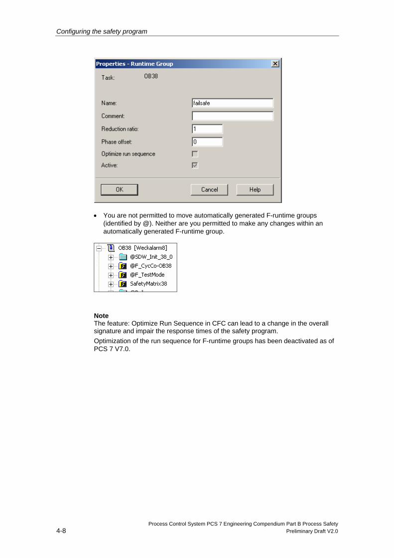
• An F-runtime group must retain the default for the runtime properties reduction ratio and phase offset as follows:
- Reduction ratio = 1
- Phase offset = 0
You are not permitted to modify these values.
Configuring the safety program
Process Control System PCS 7 Engineering Compendium Part B Process Safety 4-8 Preliminary Draft V2.0
• You are not permitted to move automatically generated F-runtime groups (identified by @). Neither are you permitted to make any changes within an automatically generated F-runtime group.
Note
The feature: Optimize Run Sequence in CFC can lead to a change in the overall signature and impair the response times of the safety program. Optimization of the run sequence for F-runtime groups has been deactivated as of PCS 7 V7.0.
Configuring the safety program
Process Control System PCS 7 Engineering Compendium Part B Process Safety Preliminary Draft V2.0 4-9
4.3.9 F-shutdown groups
An F-shutdown group is a self-contained unit in your safety program. It contains user logic which is executed or shut down simultaneously. The F-shutdown group contains one or a number of F-runtime groups which are assigned to a common task (OB). You can choose whether an error during execution of the safety program will lead to a complete shutdown of the entire safety program (complete shutdown) or a partial shutdown (in other words, only the F-shutdown group in which the error occurred will be shut down).
F-blocks need to use special communications blocks (F_S_xx, F_R_xx) for data exchange between F-shutdown groups.
All F-channel drivers for a common F-I/O need to be located in the same F-shutdown group.
Rules for F-shutdown groups in the safety program
• You are not permitted to directly interconnect F-blocks belonging to different F-shutdown groups.
Note
You will find additional information in chapter 4.6 "Programming data exchange between F-shutdown groups ".
• All F-channel drivers belonging to the same F-I/O need to be located in the same F-shutdown group.
Defining F-shutdown groups As soon as you place F-blocks in the CFC editor for the first time, all F-runtime groups in one OB 3x will combine in an F-shutdown group. You can configure each F-runtime group as the last F-runtime group in an F-shutdown group by placing the "selection block" F_PSG_M accordingly. The F-system will then create a new F-shutdown group for all subsequent F-runtime groups until another F_PSG_M block is found.
Distribution/Combination by means of manual placing of F_PSG_M If you add or delete one or a number of F_PSG_M blocks in your project, the order of your F-shutdown groups will change. If you make a change to the layout of your F-shutdown groups, you must make sure that the F-module drivers and all assigned F-channel drivers are integrated in the same F-shutdown group.
You can split one F-shutdown group into two F-shutdown groups.
Configuring the safety program
Process Control System PCS 7 Engineering Compendium Part B Process Safety 4-10 Preliminary Draft V2.0
To do this, in the CFC editor's runtime editor, place the F_PSG_M block in the last F-runtime group which is to be assigned to the first F-shutdown group. All subsequent F-runtime groups will then be assigned to the second F-shutdown group.
The number of F-shutdown groups is limited to 110 in all tasks. The number of F-shutdown groups in a task is unlimited.
If you combine a number of F-shutdown groups which exchange data via F-communications blocks in a single F-shutdown group, you will need to remove this F-communications block and replace it with direct interconnections.
4.3.10 How F-blocks with floating-point operations respond to number range overflows
In the context of analog value processing, number range overflows/underflows can occur during arithmetic calculations.
As of F-system V6.0, the response is as follows:
The results "Overflow (± infinite)", "Denormalized floating-point number" or "Invalid floating-point number (NaN)" are:
• Either output at the output and can be processed further by subsequent F-blocks
or
• Signaled to special outputs. A substitute value is output if necessary.
If the floating-point operation produces an invalid floating-point number (NaN) and no invalid floating-point number (NaN) existed as an address prior to this, the following diagnostics event will be entered in the F-CPU's diagnostics buffer:
"Safety program: Invalid REAL number in DB" (event ID 16#75D9)
You can use this entry in the diagnostics buffer to identify the F-block with the invalid floating-point number (NaN). Please also refer to the documentation for the F-blocks.
If you are not able to prevent these events from occurring in your safety program, you will need to decide, on the basis of your application, whether you wish to respond to them in your safety program.
Configuring the safety program
Process Control System PCS 7 Engineering Compendium Part B Process Safety Preliminary Draft V2.0 4-11
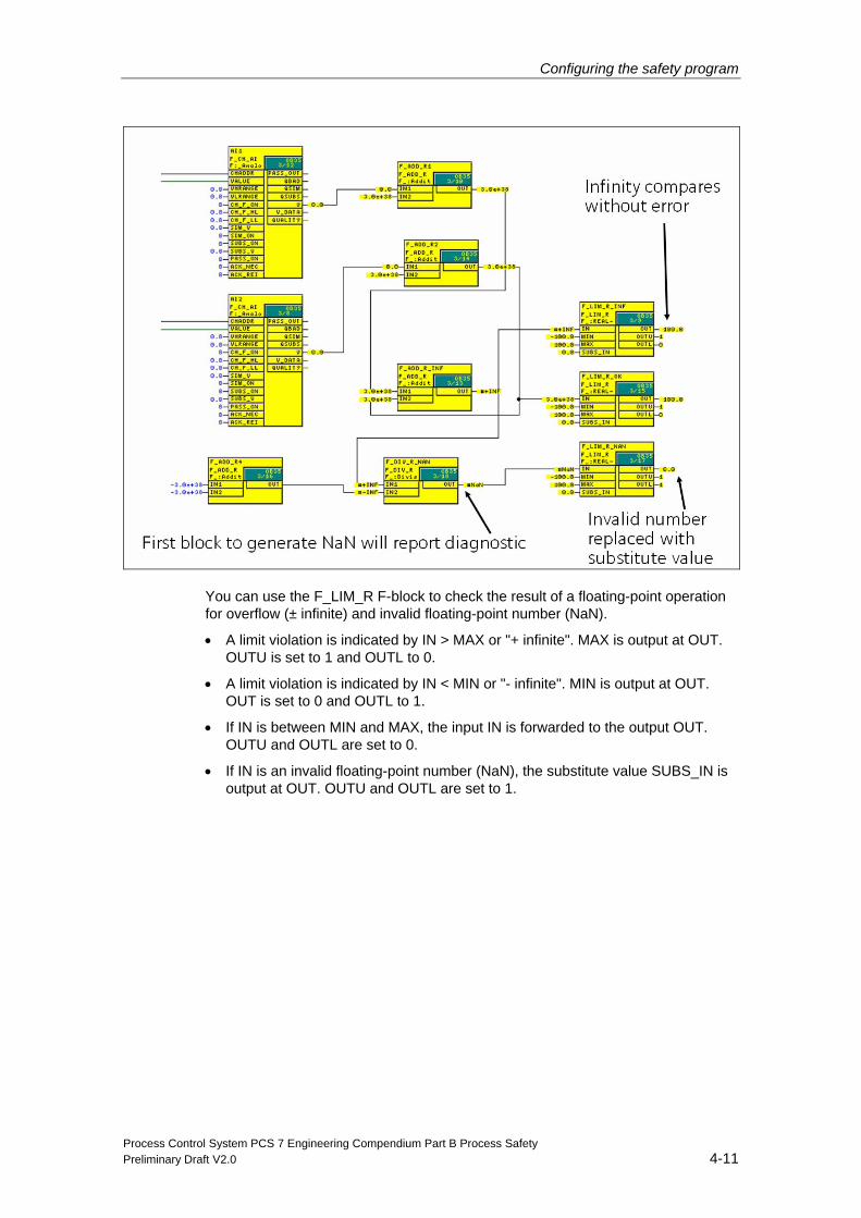
You can use the F_LIM_R F-block to check the result of a floating-point operation for overflow (± infinite) and invalid floating-point number (NaN).
• A limit violation is indicated by IN > MAX or "+ infinite". MAX is output at OUT. OUTU is set to 1 and OUTL to 0.
• A limit violation is indicated by IN < MIN or "- infinite". MIN is output at OUT. OUT is set to 0 and OUTL to 1.
• If IN is between MIN and MAX, the input IN is forwarded to the output OUT. OUTU and OUTL are set to 0.
• If IN is an invalid floating-point number (NaN), the substitute value SUBS_IN is output at OUT. OUTU and OUTL are set to 1.
Configuring the safety program
Process Control System PCS 7 Engineering Compendium Part B Process Safety 4-12 Preliminary Draft V2.0
4.4 F-STOP
In the event of an F-STOP, either the entire program (complete shutdown) or just the F-shutdown group (partial shutdown) containing the faulty F-runtime group is shut down. All F-runtime groups in an F-shutdown group are shut down at the same time. The F-CPU's standard user program will continue to run in the event of an F-STOP.
When F-shutdown groups are shut down:
• The outputs of the F-I/Os driven by the F-shutdown group are passivated.
• As of S7-F-System V6.0: The F-channel drivers of the F-shutdown group set the outputs QBAD to "1" and QUALITY to "0".
• Safety-related communication between the F-shutdown group and other F-CPUs is interrupted.
• Data exchange between the F-shutdown group and other F-shutdown groups is interrupted.
• Where data exchange between the safety program and the standard user program is concerned, the standard user program is provided with the last valid values.
• Block F_SHUTDN generates a message which is displayed automatically on the PCS 7 OS. As of S7-F Systems V6.0:
- Safety program: Partial shutdown
- Safety program: Complete shutdown
• The corresponding diagnostics events are written to the F-CPU's diagnostics buffer.
4.4.1 Complete shutdown
All of the F-CPU's F-shutdown groups are shut down. Shutdown proceeds in the following order:
• First, the F-shutdown group in which the error was detected is shut down.
• All other F-shutdown groups are then shut down within double the time period you set as the F-monitoring time for the slowest OB.
4.4.2 Partial shutdown
Only the F-blocks in the F-shutdown group in which the error was detected are shut down.
Configuring the safety program
Process Control System PCS 7 Engineering Compendium Part B Process Safety Preliminary Draft V2.0 4-13
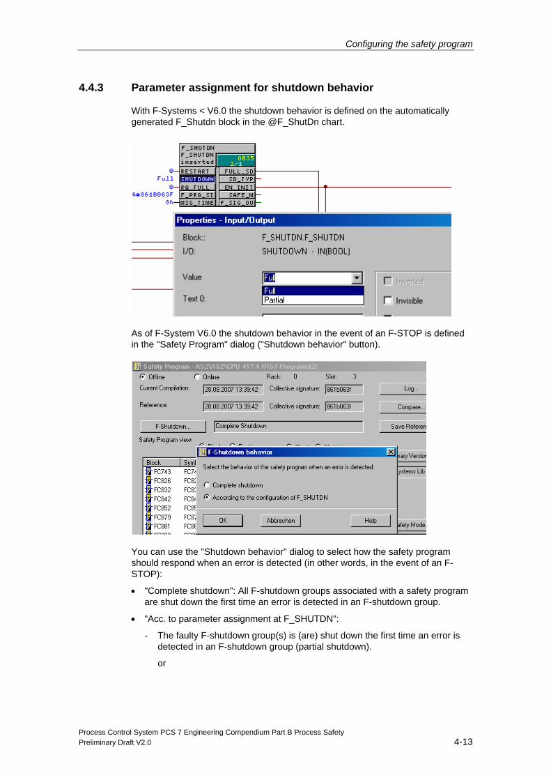
4.4.3 Parameter assignment for shutdown behavior
With F-Systems < V6.0 the shutdown behavior is defined on the automatically generated F_Shutdn block in the @F_ShutDn chart.
As of F-System V6.0 the shutdown behavior in the event of an F-STOP is defined in the "Safety Program" dialog ("Shutdown behavior" button).
You can use the "Shutdown behavior" dialog to select how the safety program should respond when an error is detected (in other words, in the event of an F-STOP):
• "Complete shutdown": All F-shutdown groups associated with a safety program are shut down the first time an error is detected in an F-shutdown group.
• "Acc. to parameter assignment at F_SHUTDN":
- The faulty F-shutdown group(s) is (are) shut down the first time an error is detected in an F-shutdown group (partial shutdown).
or
Configuring the safety program
Process Control System PCS 7 Engineering Compendium Part B Process Safety 4-14 Preliminary Draft V2.0
- All F-shutdown groups associated with a safety program are shut down the first time an error is detected in an F-shutdown group.
If you change the shutdown behavior, you must recompile the F-program.
4.4.4 Causes of errors
Errors triggering an F-STOP:
• Distortion of
- Data
- Program sequence
- Code
• CPU error
Errors which always trigger a complete shutdown:
Irrespective of the parameter assignment of F-STOP, a complete shutdown is always triggered in the event of an OB request error (caused for example by a CPU/OB overload).
Configuring the safety program
Process Control System PCS 7 Engineering Compendium Part B Process Safety Preliminary Draft V2.0 4-15
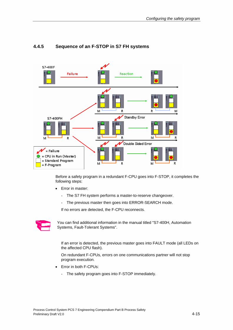
4.4.5 Sequence of an F-STOP in S7 FH systems
Before a safety program in a redundant F-CPU goes into F-STOP, it completes the following steps:
• Error in master:
- The S7 FH system performs a master-to-reserve changeover.
- The previous master then goes into ERROR-SEARCH mode.
If no errors are detected, the F-CPU reconnects.
You can find additional information in the manual titled "S7-400H, Automation Systems, Fault-Tolerant Systems”.
If an error is detected, the previous master goes into FAULT mode (all LEDs on the affected CPU flash).
On redundant F-CPUs, errors on one communications partner will not stop program execution.
• Error in both F-CPUs:
- The safety program goes into F-STOP immediately.
Configuring the safety program
Process Control System PCS 7 Engineering Compendium Part B Process Safety 4-16 Preliminary Draft V2.0
4.4.6 Exiting an F-STOP
Run an F-startup as described in the following chapter.
4.5 F-startup and (re)start protection
4.5.1 F-startup
F Systems does not make a distinction between a CPU cold restart and a CPU warm restart. The F_CHG_BO, F_CHG_R (part of the Safety Data Write function), and F_MOV_R (as of F_System V6.0) F-blocks are exceptions to this rule.
Both a CPU cold restart and a CPU warm restart will generate an F-startup. In the event of an F-startup the safety program starts up automatically with the initial values.
An F-startup is performed:
• After a CPU-STOP, if you perform an F-CPU restart (warm restart) or cold restart
• After an F-STOP, if you apply a positive edge at the RESTART input of the "F_SHUTDN" F-block
Following a partial shutdown of the safety program, only the F-shutdown groups involved in the F-STOP perform an F-startup. F-shutdown groups with errors remain in F-STOP.
Startup of the safety program with the initial values of the F-blocks can also be triggered by a handling error or an internal error. If the process does not permit this, you will need to program (re)start protection in the safety program: The output of process values must be blocked until a manual enable is set. The enable can only be set once process values can be output without risk and errors have been eliminated.
You must take one of the following actions once errors have been eliminated:
• User acknowledgment on the F-channel driver (F_CH_xx) by means of an edge on the ACK_REI input parameter
• User acknowledgment on the F_RCVBO/F_RCVR or F_RDS_BO F-block
Where the F_R_BO and F_R_R F-blocks used for data exchange between F-runtime groups are concerned, receive data is reintegrated automatically.
4.5.2 (Re)start protection
If the process does not permit the safety program to start up automatically with the initial values, you will need to program a response to F-startup.
The F_START is used to signal an F-startup of the safety program with the initial values. The COLDSTRT output parameter tells you that an F-startup has been triggered.
Configuring the safety program
Process Control System PCS 7 Engineering Compendium Part B Process Safety Preliminary Draft V2.0 4-17
For an example of use, see the manual “Programmable Controllers S7 F/FH Systems”.
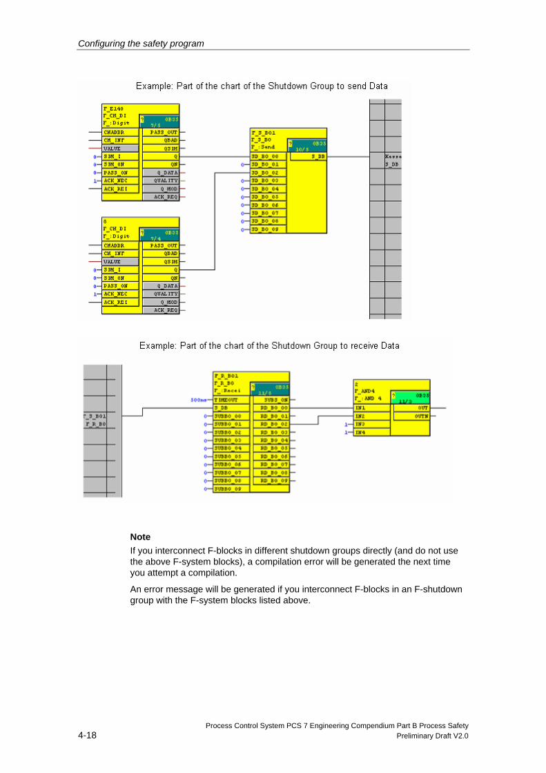
4.6 Data exchange between F-shutdown groups
If you wish to exchange data between two F-shutdown modules, you are not permitted to interconnect the inputs and outputs directly. You need to use the following F-system blocks for data exchange between F-blocks in different F-shutdown groups:
F-block Description
F_S_R/F_R_R Safe transmission of 5 data items of the F_REAL type
F_S_BO/F_R_BO Safe transmission of 5 data items of the F_BOOL type
Procedure 1. In the F-shutdown group from which data is to be transmitted, add an F_S_R or
F_S_BO type F-block.
2. In the F-shutdown group to which data is to be transmitted, add an F_R_R or F_R_BO type F-block.
3. Interconnect the SD_R_xx inputs of the F_S_R or the SD_BO_xx inputs of the F_S_BO with the data to be transmitted.
4. Interconnect the RD_R_xx outputs of the F_R_R or the RD_BO_xx outputs of the F_R_BO with the inputs of the F-block for further processing of the received data.
5. Interconnect the S_DB output of the send block with the S_DB input of the associated receive block.
6. Parameterize the TIMEOUT inputs of the F_R_R and F_R_BO receive blocks with the required F-monitoring time.
Note
You will find information about calculating the F-monitoring time in Chapter 4.12.
Configuring the safety program
Process Control System PCS 7 Engineering Compendium Part B Process Safety 4-18 Preliminary Draft V2.0
Note
If you interconnect F-blocks in different shutdown groups directly (and do not use the above F-system blocks), a compilation error will be generated the next time you attempt a compilation.
An error message will be generated if you interconnect F-blocks in an F-shutdown group with the F-system blocks listed above.

Configuring the safety program
Process Control System PCS 7 Engineering Compendium Part B Process Safety Preliminary Draft V2.0 4-19
I/O access via F-driver blocks In S7 F/FH systems, F-I/O modules are accessed via F-driver blocks and not via the process image. There are two types of driver block:
• F-channel driver (e.g. F_CH_xx) for access to the input/output channels of F-SMs.
One F-channel driver block is required for every input or output channel used. Only one F-channel driver is required for redundant channels.
In your safety program, F-channel drivers provide the interface with a channel of an F-I/O and perform signal processing. F-channel drivers vary depending on the F-I/O. They are placed and interconnected in the safety program by the user.
• F-module driver (F_M_XX or as of F-Systems V6.0: F_PS_12) for ProfiSafe communication between the safety program and the fail-safe I/O modules.
One F-module driver is required for each module. The F-module drivers required are placed and interconnected automatically by the CFC module driver wizard.
Configuring the safety program
Process Control System PCS 7 Engineering Compendium Part B Process Safety 4-20 Preliminary Draft V2.0
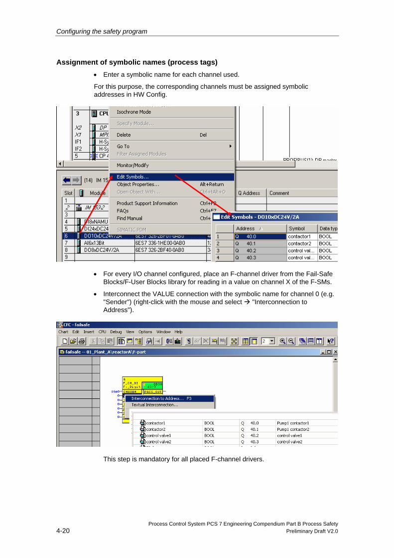
Assignment of symbolic names (process tags) • Enter a symbolic name for each channel used.
For this purpose, the corresponding channels must be assigned symbolic addresses in HW Config.
• For every I/O channel configured, place an F-channel driver from the Fail-Safe Blocks/F-User Blocks library for reading in a value on channel X of the F-SMs.
• Interconnect the VALUE connection with the symbolic name for channel 0 (e.g. "Sender") (right-click with the mouse and select "Interconnection to Address").
This step is mandatory for all placed F-channel drivers.
Configuring the safety program
Process Control System PCS 7 Engineering Compendium Part B Process Safety Preliminary Draft V2.0 4-21
4.7 Passivation and reintegration of input/output modules
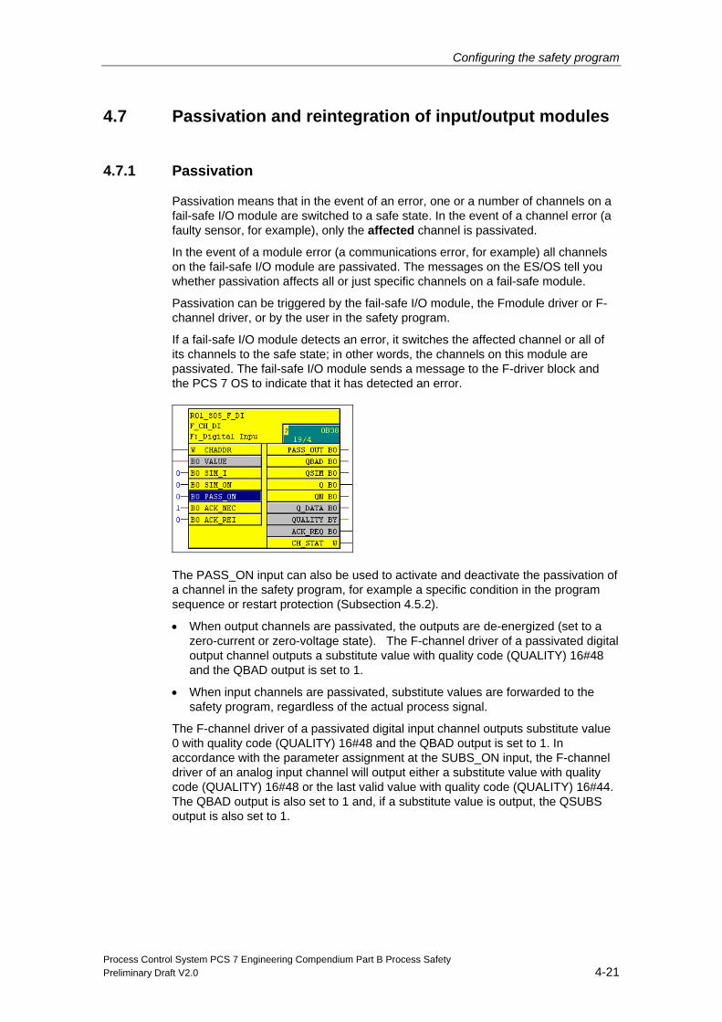
4.7.1 Passivation
Passivation means that in the event of an error, one or a number of channels on a fail-safe I/O module are switched to a safe state. In the event of a channel error (a faulty sensor, for example), only the affected channel is passivated.
In the event of a module error (a communications error, for example) all channels on the fail-safe I/O module are passivated. The messages on the ES/OS tell you whether passivation affects all or just specific channels on a fail-safe module.
Passivation can be triggered by the fail-safe I/O module, the Fmodule driver or F-channel driver, or by the user in the safety program.
If a fail-safe I/O module detects an error, it switches the affected channel or all of its channels to the safe state; in other words, the channels on this module are passivated. The fail-safe I/O module sends a message to the F-driver block and the PCS 7 OS to indicate that it has detected an error.
The PASS_ON input can also be used to activate and deactivate the passivation of a channel in the safety program, for example a specific condition in the program sequence or restart protection (Subsection 4.5.2).
• When output channels are passivated, the outputs are de-energized (set to a zero-current or zero-voltage state). The F-channel driver of a passivated digital output channel outputs a substitute value with quality code (QUALITY) 16#48 and the QBAD output is set to 1.
• When input channels are passivated, substitute values are forwarded to the safety program, regardless of the actual process signal.
The F-channel driver of a passivated digital input channel outputs substitute value 0 with quality code (QUALITY) 16#48 and the QBAD output is set to 1. In accordance with the parameter assignment at the SUBS_ON input, the F-channel driver of an analog input channel will output either a substitute value with quality code (QUALITY) 16#48 or the last valid value with quality code (QUALITY) 16#44. The QBAD output is also set to 1 and, if a substitute value is output, the QSUBS output is also set to 1.
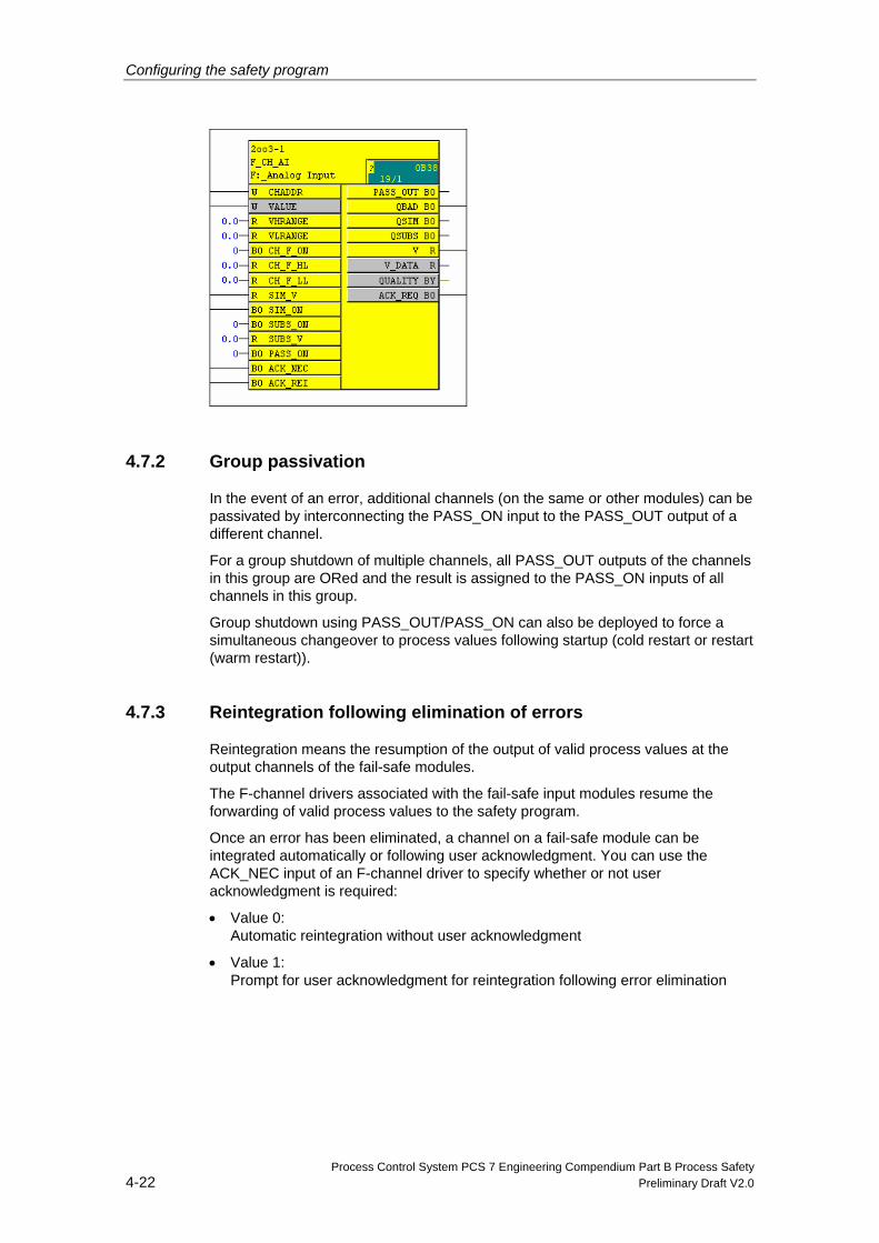
Configuring the safety program
Process Control System PCS 7 Engineering Compendium Part B Process Safety 4-22 Preliminary Draft V2.0
4.7.2 Group passivation
In the event of an error, additional channels (on the same or other modules) can be passivated by interconnecting the PASS_ON input to the PASS_OUT output of a different channel.
For a group shutdown of multiple channels, all PASS_OUT outputs of the channels in this group are ORed and the result is assigned to the PASS_ON inputs of all channels in this group.
Group shutdown using PASS_OUT/PASS_ON can also be deployed to force a simultaneous changeover to process values following startup (cold restart or restart (warm restart)).
4.7.3 Reintegration following elimination of errors
Reintegration means the resumption of the output of valid process values at the output channels of the fail-safe modules.
The F-channel drivers associated with the fail-safe input modules resume the forwarding of valid process values to the safety program.
Once an error has been eliminated, a channel on a fail-safe module can be integrated automatically or following user acknowledgment. You can use the ACK_NEC input of an F-channel driver to specify whether or not user acknowledgment is required:
• Value 0: Automatic reintegration without user acknowledgment
• Value 1: Prompt for user acknowledgment for reintegration following error elimination
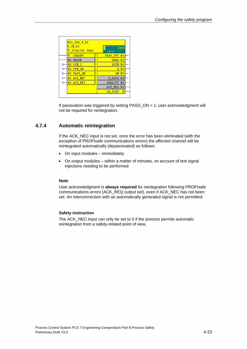
Configuring the safety program
Process Control System PCS 7 Engineering Compendium Part B Process Safety Preliminary Draft V2.0 4-23
If passivation was triggered by setting PASS_ON = 1, user acknowledgment will not be required for reintegration.
4.7.4 Automatic reintegration
If the ACK_NEC input is not set, once the error has been eliminated (with the exception of PROFIsafe communications errors) the affected channel will be reintegrated automatically (depassivated) as follows:
• On input modules – immediately
• On output modules – within a matter of minutes, on account of test signal injections needing to be performed
Note
User acknowledgment is always required for reintegration following PROFIsafe communications errors (ACK_REQ output set), even if ACK_NEC has not been set. An interconnection with an automatically generated signal is not permitted.
Safety instruction
The ACK_NEC input can only be set to 0 if the process permits automatic reintegration from a safety-related point of view.
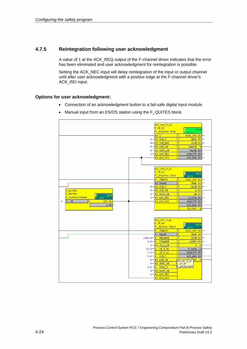
Configuring the safety program
Process Control System PCS 7 Engineering Compendium Part B Process Safety 4-24 Preliminary Draft V2.0
4.7.5 Reintegration following user acknowledgment
A value of 1 at the ACK_REQ output of the F-channel driver indicates that the error has been eliminated and user acknowledgment for reintegration is possible.
Setting the ACK_NEC input will delay reintegration of the input or output channel until after user acknowledgment with a positive edge at the F-channel driver's ACK_REI input.
Options for user acknowledgment: • Connection of an acknowledgment button to a fail-safe digital input module.
• Manual input from an ES/OS station using the F_QUITES block.
Configuring the safety program
Process Control System PCS 7 Engineering Compendium Part B Process Safety Preliminary Draft V2.0 4-25
If you use an acknowledgment button for user acknowledgment, in the event of a PROFIsafe communications error on the F-I/O module to which the acknowledgment button has been connected, you will no longer be able to trigger acknowledgment to reintegrate this F-I/O module. This "block" can only be lifted by means of an F-CPU STOP/RUN transition. Therefore, we recommend that for the acknowledgment to reintegrate an F-I/O module to which an acknowledgment button has been connected, a means of acknowledgment via an OS is also provided.
An automatic user acknowledgment is not permissible.
How to program user acknowledgment via an OS 7. Add the F_QUITES F-block to your safety program. You can access the
acknowledgment signal for evaluation for user acknowledgments at the output OUT of F_QUITES.
8. Interconnect the F-channel driver's ACK_REI input to the output OUT of F_QUITES.
9. On your OS, set up a field for the manual input of the "Acknowledge value" "6" (1st acknowledgment step) and the "Acknowledge value" "9" (2nd acknowledgment value) at the input IN of F_QUITES.
10. Optional: On your OS, evaluate the output Q of F_QUITES to show the time window within which the 2nd acknowledgment step must be completed or to show that the 1st acknowledgment step has already been completed.
Safety instruction
Automatic reintegration using F_QUITES:
The non-safety-related input IN of F_QUITES must not be interconnected with a signal or described by a signal which generates the above condition (change from 6 to 9 within a minute) automatically for a fail-safe acknowledgment. Fail-safe acknowledgment must only be generated by means of a conscious manual entry on the ES/OS (not automatically in the program).
4.7.6 Example implementation of F-user acknowledgment on the OS
All ACK_REQ channel driver outputs are grouped by means of an OR in the standard user program and thus made available to the OS via a DIG_MON block.
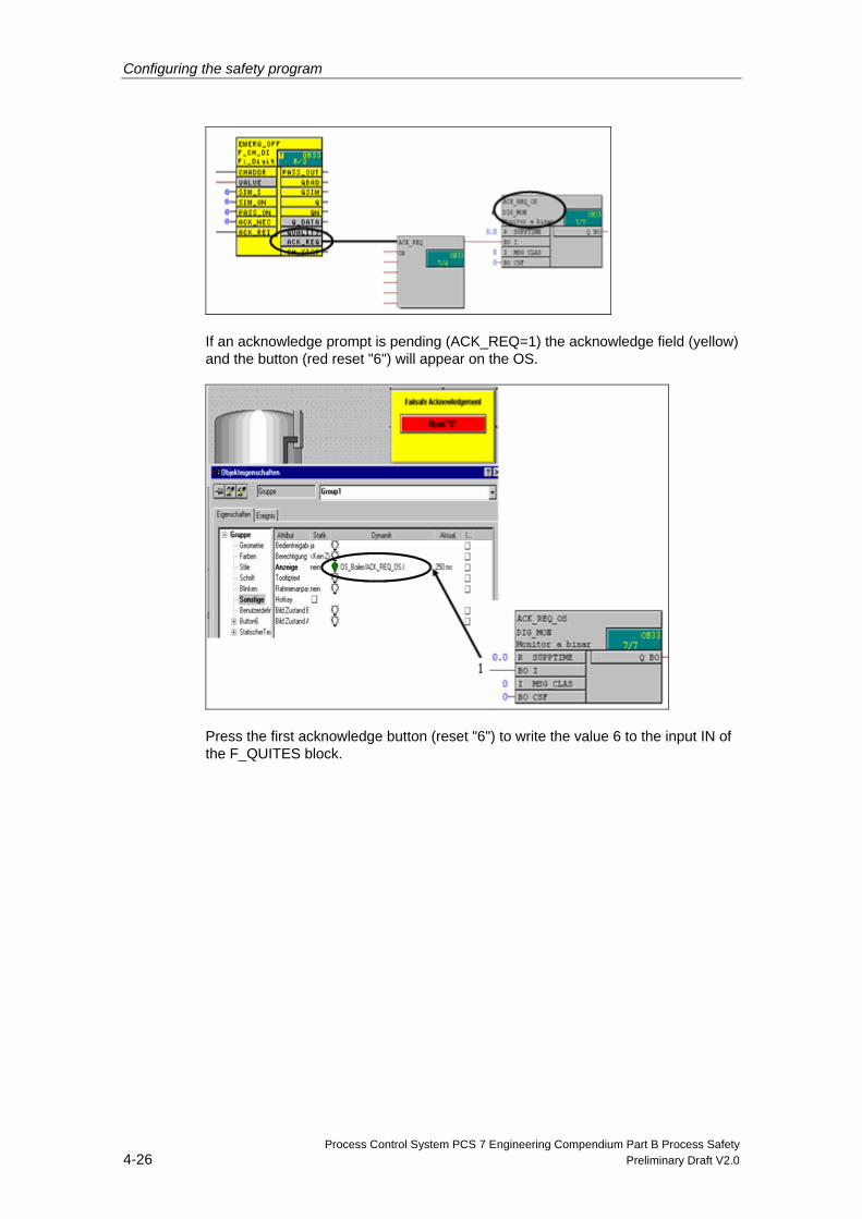
Configuring the safety program
Process Control System PCS 7 Engineering Compendium Part B Process Safety 4-26 Preliminary Draft V2.0
If an acknowledge prompt is pending (ACK_REQ=1) the acknowledge field (yellow) and the button (red reset "6") will appear on the OS.
Press the first acknowledge button (reset "6") to write the value 6 to the input IN of the F_QUITES block.
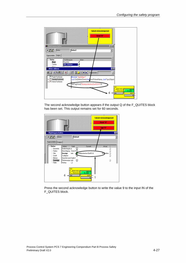
Configuring the safety program
Process Control System PCS 7 Engineering Compendium Part B Process Safety Preliminary Draft V2.0 4-27
The second acknowledge button appears if the output Q of the F_QUITES block has been set. This output remains set for 60 seconds.
Press the second acknowledge button to write the value 9 to the input IN of the F_QUITES block.
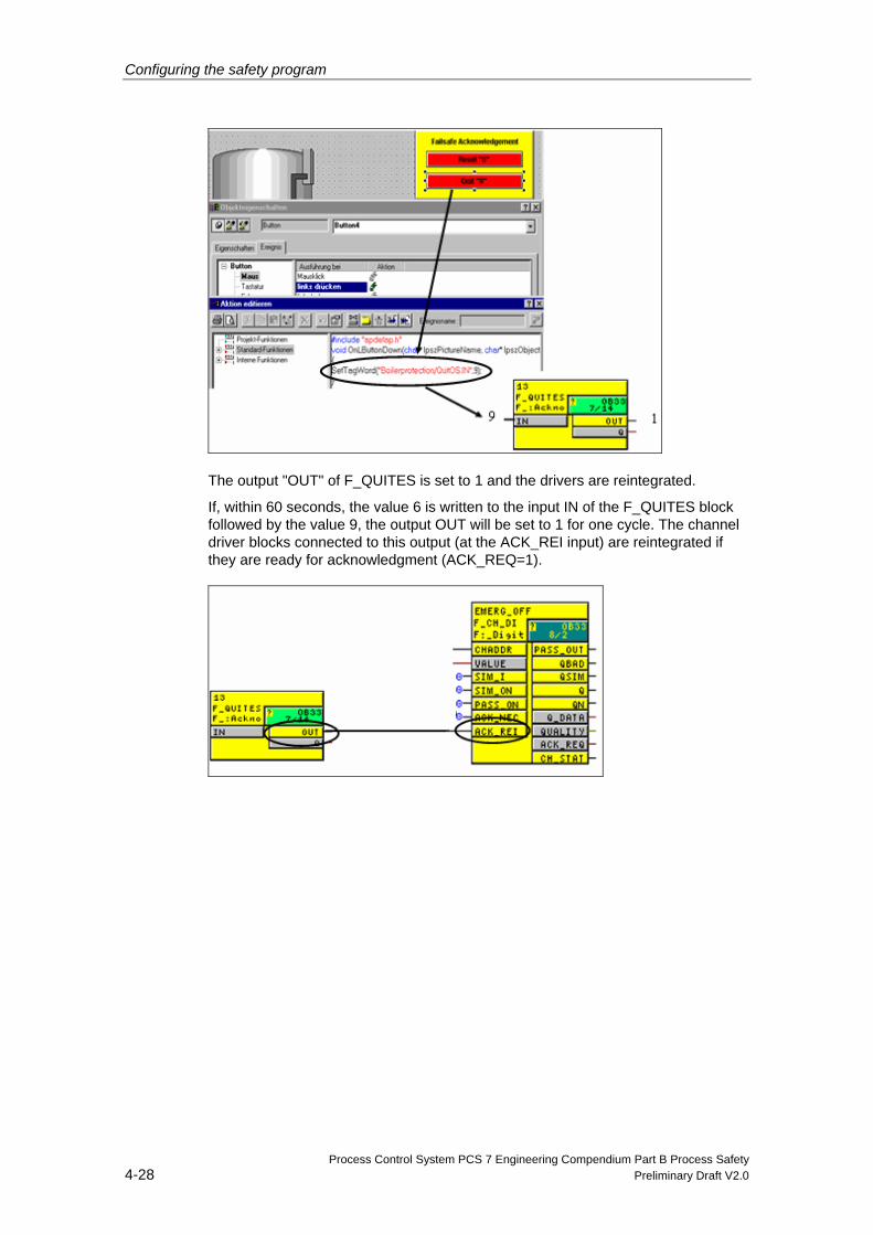
Configuring the safety program
Process Control System PCS 7 Engineering Compendium Part B Process Safety 4-28 Preliminary Draft V2.0
The output "OUT" of F_QUITES is set to 1 and the drivers are reintegrated.
If, within 60 seconds, the value 6 is written to the input IN of the F_QUITES block followed by the value 9, the output OUT will be set to 1 for one cycle. The channel driver blocks connected to this output (at the ACK_REI input) are reintegrated if they are ready for acknowledgment (ACK_REQ=1).
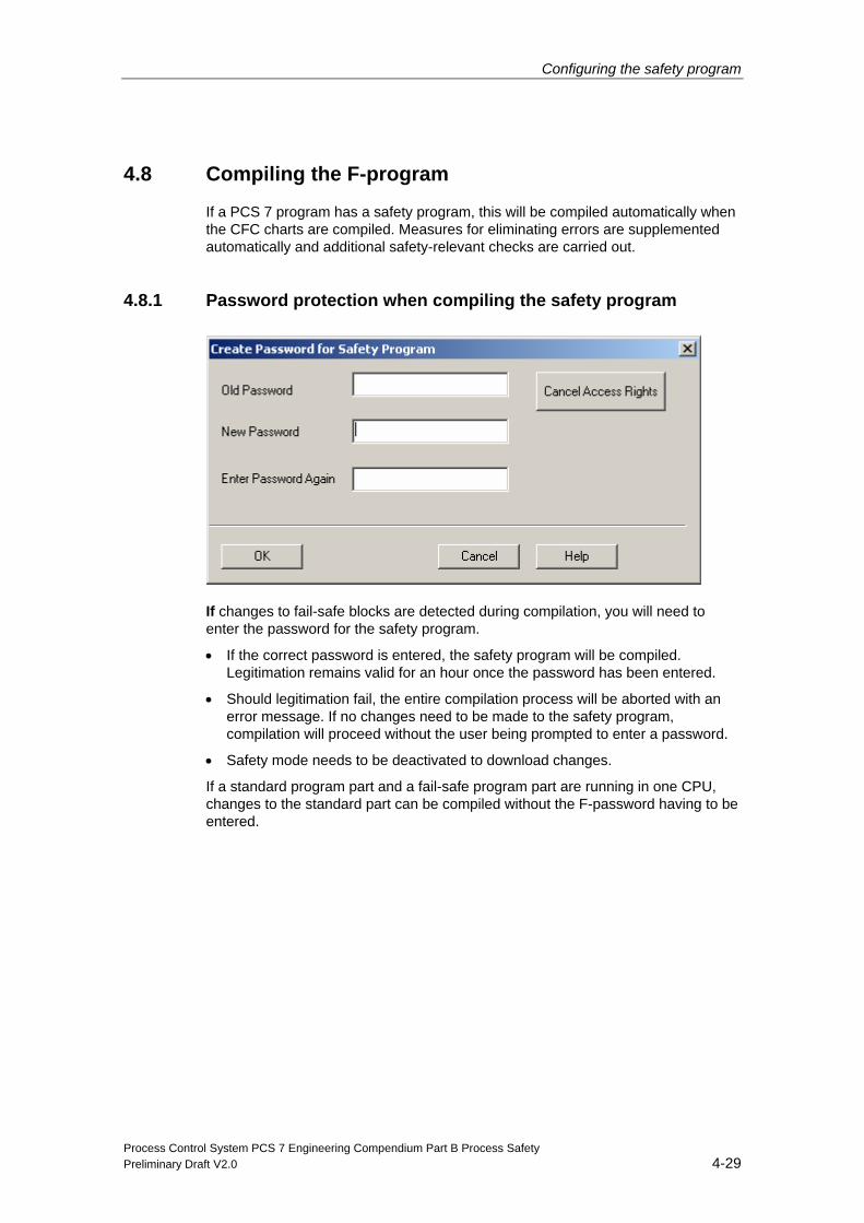
Configuring the safety program
Process Control System PCS 7 Engineering Compendium Part B Process Safety Preliminary Draft V2.0 4-29
4.8 Compiling the F-program
If a PCS 7 program has a safety program, this will be compiled automatically when the CFC charts are compiled. Measures for eliminating errors are supplemented automatically and additional safety-relevant checks are carried out.
4.8.1 Password protection when compiling the safety program
If changes to fail-safe blocks are detected during compilation, you will need to enter the password for the safety program.
• If the correct password is entered, the safety program will be compiled. Legitimation remains valid for an hour once the password has been entered.
• Should legitimation fail, the entire compilation process will be aborted with an error message. If no changes need to be made to the safety program, compilation will proceed without the user being prompted to enter a password.
• Safety mode needs to be deactivated to download changes.
If a standard program part and a fail-safe program part are running in one CPU, changes to the standard part can be compiled without the F-password having to be entered.
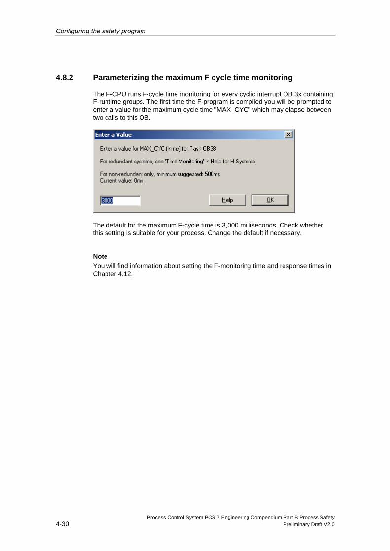
Configuring the safety program
Process Control System PCS 7 Engineering Compendium Part B Process Safety 4-30 Preliminary Draft V2.0
4.8.2 Parameterizing the maximum F cycle time monitoring
The F-CPU runs F-cycle time monitoring for every cyclic interrupt OB 3x containing F-runtime groups. The first time the F-program is compiled you will be prompted to enter a value for the maximum cycle time "MAX_CYC" which may elapse between two calls to this OB.
The default for the maximum F-cycle time is 3,000 milliseconds. Check whether this setting is suitable for your process. Change the default if necessary.
Note
You will find information about setting the F-monitoring time and response times in Chapter 4.12.
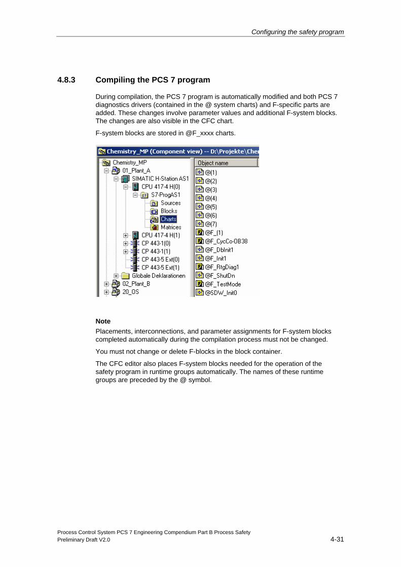
Configuring the safety program
Process Control System PCS 7 Engineering Compendium Part B Process Safety Preliminary Draft V2.0 4-31
4.8.3 Compiling the PCS 7 program
During compilation, the PCS 7 program is automatically modified and both PCS 7 diagnostics drivers (contained in the @ system charts) and F-specific parts are added. These changes involve parameter values and additional F-system blocks. The changes are also visible in the CFC chart.
F-system blocks are stored in @F_xxxx charts.
Note
Placements, interconnections, and parameter assignments for F-system blocks completed automatically during the compilation process must not be changed.
You must not change or delete F-blocks in the block container.
The CFC editor also places F-system blocks needed for the operation of the safety program in runtime groups automatically. The names of these runtime groups are preceded by the @ symbol.
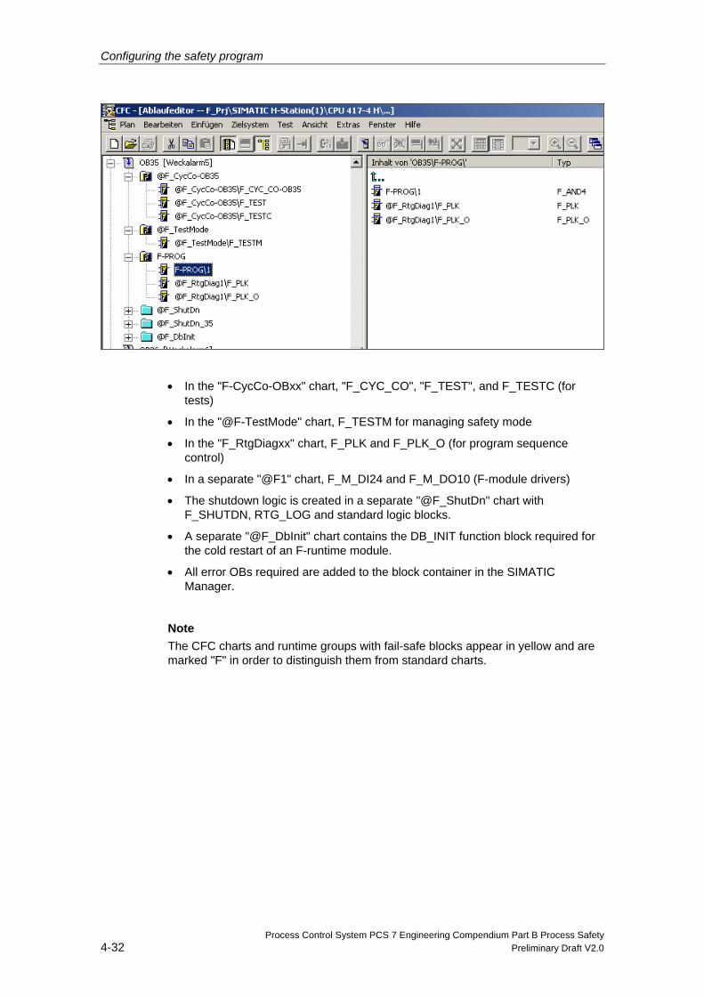
Configuring the safety program
Process Control System PCS 7 Engineering Compendium Part B Process Safety 4-32 Preliminary Draft V2.0
• In the "F-CycCo-OBxx" chart, "F_CYC_CO", "F_TEST", and F_TESTC (for tests)
• In the "@F-TestMode" chart, F_TESTM for managing safety mode
• In the "F_RtgDiagxx" chart, F_PLK and F_PLK_O (for program sequence control)
• In a separate "@F1" chart, F_M_DI24 and F_M_DO10 (F-module drivers)
• The shutdown logic is created in a separate "@F_ShutDn" chart with F_SHUTDN, RTG_LOG and standard logic blocks.
• A separate "@F_DbInit" chart contains the DB_INIT function block required for the cold restart of an F-runtime module.
• All error OBs required are added to the block container in the SIMATIC Manager.
Note
The CFC charts and runtime groups with fail-safe blocks appear in yellow and are marked "F" in order to distinguish them from standard charts.
Configuring the safety program
Process Control System PCS 7 Engineering Compendium Part B Process Safety Preliminary Draft V2.0 4-33
4.9 Safety mode and downloading the safety program
Safety mode of the safety program in the F-CPU can be temporarily deactivated and reactivated. This enables you to make changes to the safety program in RUN mode.
4.9.1 Deactivating safety mode
In safety mode, all mechanisms for detecting and responding to errors are activated. In this state it is not possible to modify the safety program in active operation (RUN).
You can use the "Safety mode..." button in the "Safety Program" dialog to activate or deactivate safety mode in the F-CPU in RUN mode. Changes to the safety program in RUN mode can only be downloaded if you temporarily deactivate safety mode by clicking this button.
The window underneath this button shows you whether safety mode is "activated" or "deactivated". If the safety program does not match the safety program in the F-CPU or communication with the F-CPU has failed, "unknown" will appear here.
You can also use the SAFE_M output at the F_SHUTDN block (located in the @F_ShutDn chart) to determine whether or not safety mode has been activated.
Note
If simulation mode has been activated, you will not be able to deactivate safety mode or make any changes.
Requirements • The CPU is in RUN (mode selector in RUN or RUN-P) and
• Safety mode has been activated
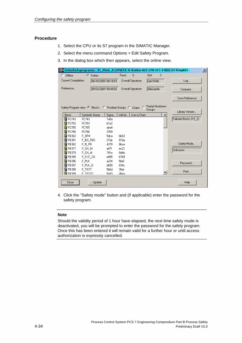
Configuring the safety program
Process Control System PCS 7 Engineering Compendium Part B Process Safety 4-34 Preliminary Draft V2.0
Procedure 1. Select the CPU or its S7 program in the SIMATIC Manager.
2. Select the menu command Options > Edit Safety Program.
3. In the dialog box which then appears, select the online view.
4. Click the "Safety mode" button and (if applicable) enter the password for the safety program.
Note
Should the validity period of 1 hour have elapsed, the next time safety mode is deactivated, you will be prompted to enter the password for the safety program. Once this has been entered it will remain valid for a further hour or until access authorization is expressly cancelled.
Configuring the safety program
Process Control System PCS 7 Engineering Compendium Part B Process Safety Preliminary Draft V2.0 4-35
4.9.2 Activating safety mode
Following a download of changes, you will need to reactivate safety mode in order to ensure secure execution of the the safety program.
Procedure 1. Select the CPU or its S7 program in the SIMATIC Manager.
2. Select the menu command "Options Edit Safety Program".
3. In the dialog box which then appears, select the online view.
4. Click the "Safety mode" button.
Note
If, when safety mode is deactivated, the safety program detects a safety-related error, it will disable the option to activate safety mode. A corresponding message will appear indicating how you can rectify the problem.
4.9.3 Downloading the safety program
After compilation, you can download the CFC program to the target system (CPU). Depending on whether safety mode is activated or deactivated, you can download the entire safety program or changes to it as follows:
Download CPU in STOP CPU in RUN safety
mode active CPU in RUN safety mode not active
Of the entire program Possible Not possible Not possible
Of changes in the standard program
Not possible Possible Possible
Of changes in the safety program
Not possible Not possible Possible
Requirements • The station's hardware configuration data has been downloaded to the CPU.
• The user program has been compiled without errors.
• You have access rights to the CPU.
• There is an online connection between the CPU and your ES.
Configuring the safety program
Process Control System PCS 7 Engineering Compendium Part B Process Safety 4-36 Preliminary Draft V2.0
Rules for downloading • You can only download the safety program from the CFC editor or the SIMATIC
Manager via the chart folder.
• Once you have downloaded an acceptance-tested safety program, you will need to check the overall signature in the same was as during acceptance testing (see also chapter 8.3.1 "Checking overall signatures").
Procedure To download the safety program to the CPU, select the menu command "Download to CPU (entire program)" in the CFC editor. This will set the F-CPU to STOP.
Note
Before the safety program is downloaded you will be prompted to enter the CPU password if changes are detected in the fail-safe part of the program.
Result: If you enter the correct password, the safety program will be downloaded to the CPU to which the program container is assigned. If you enter an incorrect password, the download operation will not be performed. Once you have downloaded the program to the CPU, you will need to compare its overall signature in the CPU with the overall signature in the acceptance-tested printout (see also chapter 8.3.1 "Checking overall signatures"). On S7 FH systems, you need to run this comparison for both CPUs.
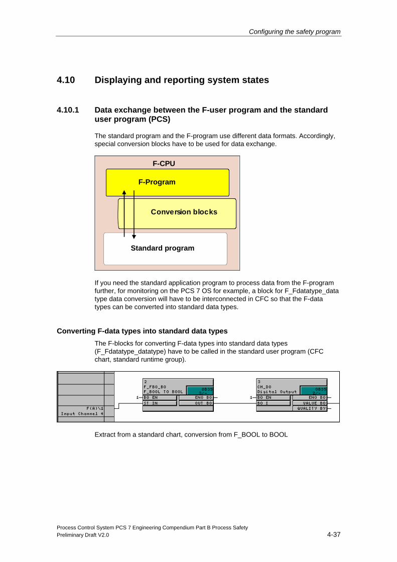
Configuring the safety program
Process Control System PCS 7 Engineering Compendium Part B Process Safety Preliminary Draft V2.0 4-37
4.10 Displaying and reporting system states
4.10.1 Data exchange between the F-user program and the standard user program (PCS)
The standard program and the F-program use different data formats. Accordingly, special conversion blocks have to be used for data exchange.
F-CPU
Standard program
F-Program
Conversion blocks
If you need the standard application program to process data from the F-program further, for monitoring on the PCS 7 OS for example, a block for F_Fdatatype_data type data conversion will have to be interconnected in CFC so that the F-data types can be converted into standard data types.
Converting F-data types into standard data types The F-blocks for converting F-data types into standard data types (F_Fdatatype_datatype) have to be called in the standard user program (CFC chart, standard runtime group).
Extract from a standard chart, conversion from F_BOOL to BOOL
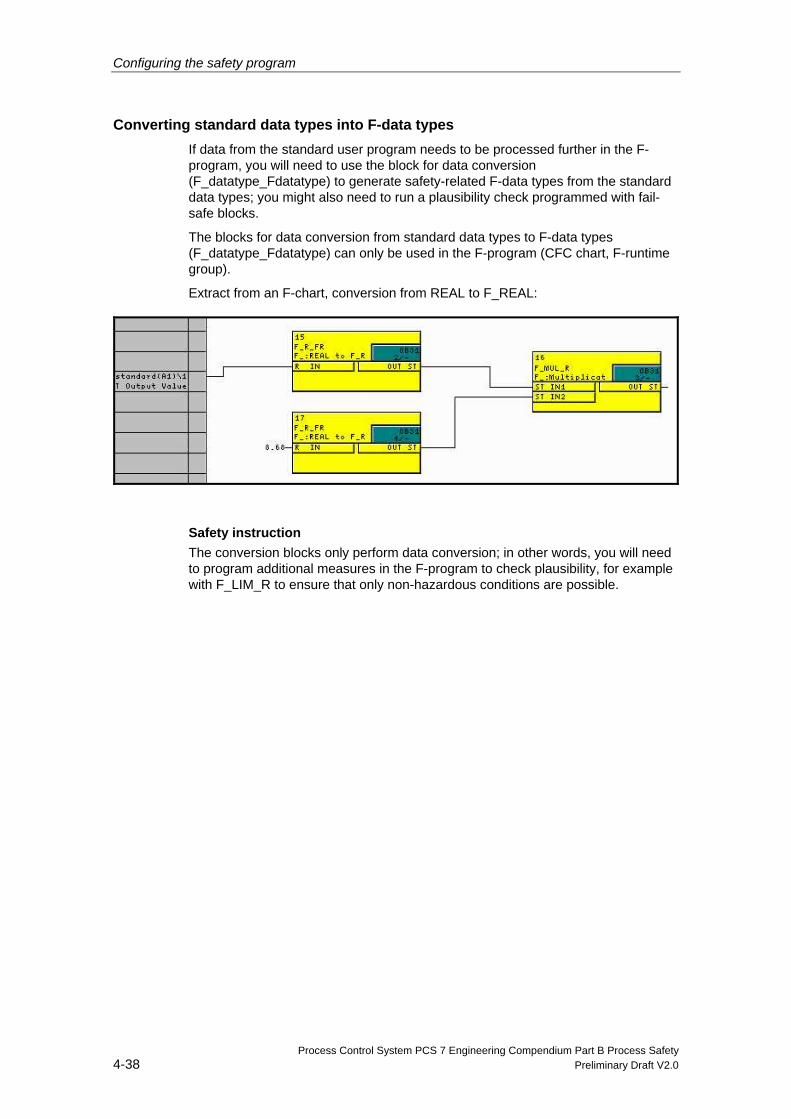
Configuring the safety program
Process Control System PCS 7 Engineering Compendium Part B Process Safety 4-38 Preliminary Draft V2.0
Converting standard data types into F-data types If data from the standard user program needs to be processed further in the F-program, you will need to use the block for data conversion (F_datatype_Fdatatype) to generate safety-related F-data types from the standard data types; you might also need to run a plausibility check programmed with fail-safe blocks.
The blocks for data conversion from standard data types to F-data types (F_datatype_Fdatatype) can only be used in the F-program (CFC chart, F-runtime group).
Extract from an F-chart, conversion from REAL to F_REAL:
Safety instruction
The conversion blocks only perform data conversion; in other words, you will need to program additional measures in the F-program to check plausibility, for example with F_LIM_R to ensure that only non-hazardous conditions are possible.
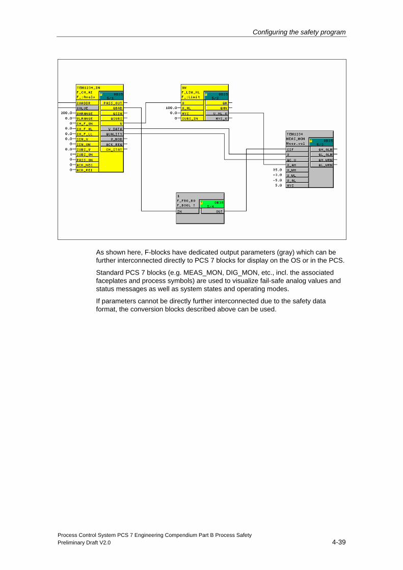
Configuring the safety program
Process Control System PCS 7 Engineering Compendium Part B Process Safety Preliminary Draft V2.0 4-39
As shown here, F-blocks have dedicated output parameters (gray) which can be further interconnected directly to PCS 7 blocks for display on the OS or in the PCS.
Standard PCS 7 blocks (e.g. MEAS_MON, DIG_MON, etc., incl. the associated faceplates and process symbols) are used to visualize fail-safe analog values and status messages as well as system states and operating modes.
If parameters cannot be directly further interconnected due to the safety data format, the conversion blocks described above can be used.
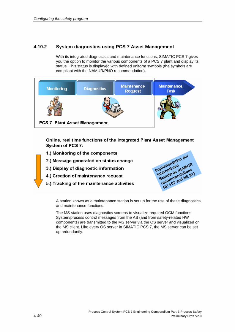
Configuring the safety program
Process Control System PCS 7 Engineering Compendium Part B Process Safety 4-40 Preliminary Draft V2.0
4.10.2 System diagnostics using PCS 7 Asset Management
With its integrated diagnostics and maintenance functions, SIMATIC PCS 7 gives you the option to monitor the various components of a PCS 7 plant and display its status. This status is displayed with defined uniform symbols (the symbols are compliant with the NAMUR/PNO recommendation).
A station known as a maintenance station is set up for the use of these diagnostics and maintenance functions.
The MS station uses diagnostics screens to visualize required OCM functions. System/process control messages from the AS (and from safety-related HW components) are transmitted to the MS server via the OS server and visualized on the MS client. Like every OS server in SIMATIC PCS 7, the MS server can be set up redundantly.
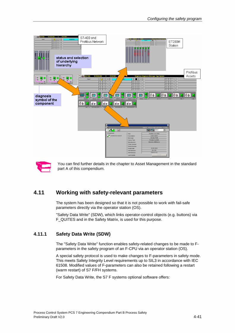
Configuring the safety program
Process Control System PCS 7 Engineering Compendium Part B Process Safety Preliminary Draft V2.0 4-41
You can find further details in the chapter to Asset Management in the standard part A of this compendium.
4.11 Working with safety-relevant parameters
The system has been designed so that it is not possible to work with fail-safe parameters directly via the operator station (OS).
"Safety Data Write" (SDW), which links operator-control objects (e.g. buttons) via F_QUITES and in the Safety Matrix, is used for this purpose.
4.11.1 Safety Data Write (SDW)
The "Safety Data Write" function enables safety-related changes to be made to F-parameters in the safety program of an F-CPU via an operator station (OS).
A special safety protocol is used to make changes to F-parameters in safety mode. This meets Safety Integrity Level requirements up to SIL3 in accordance with IEC 61508. Modified values of F-parameters can also be retained following a restart (warm restart) of S7 F/FH systems.
For Safety Data Write, the S7 F systems optional software offers:
Configuring the safety program
Process Control System PCS 7 Engineering Compendium Part B Process Safety 4-42 Preliminary Draft V2.0
• Two F-blocks which you need to integrate into the CFC charts in your safety program
- F_CHG_R: Safety Data Write for F_REAL data type F-parameters
- F_CHG_BO: Safety Data Write for F_BOOL data type F-parameters
• In addition to the associated faceplates which you need to integrate into your OS
Transaction for Safety Data Write You can use Safety Data Write to modify an F-parameter in the safety program of an F-CPU if you execute a specific sequence of operations on the OS within a specific period of time. The entire change operation is known as a "transaction".
Operator types for Safety Data Write A transaction can only be performed by an individual operator who initiates, checks, and confirms the change. However, one transaction can be performed by two operators. The first operator initiates the change (initiator) and the second re-enters, checks, and confirms the value (confirmer).
You will find more detailed information in the manual titled “Automatisierungssysteme S7 F/FH”.
4.11.2 Operator control via the OS with F-QUITES
The "F-QUITES" F-block supports the fail-safe transmission of edge-triggered pulses from the OS to the automation system. You will find an example application of F-QUITES in Chapter 4.7.6.
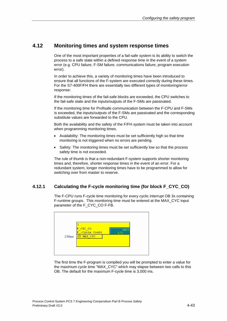
Configuring the safety program
Process Control System PCS 7 Engineering Compendium Part B Process Safety Preliminary Draft V2.0 4-43
4.12 Monitoring times and system response times
One of the most important properties of a fail-safe system is its ability to switch the process to a safe state within a defined response time in the event of a system error (e.g. CPU failure, F-SM failure, communications failure, program execution error).
In order to achieve this, a variety of monitoring times have been introduced to ensure that all functions of the F-system are executed correctly during these times. For the S7-400F/FH there are essentially two different types of monitoring/error response:
If the monitoring times of the fail-safe blocks are exceeded, the CPU switches to the fail-safe state and the inputs/outputs of the F-SMs are passivated.
If the monitoring time for Profisafe communication between the F-CPU and F-SMs is exceeded, the inputs/outputs of the F-SMs are passivated and the corresponding substitute values are forwarded to the CPU.
Both the availability and the safety of the F/FH system must be taken into account when programming monitoring times.
• Availability: The monitoring times must be set sufficiently high so that time monitoring is not triggered when no errors are pending.
• Safety: The monitoring times must be set sufficiently low so that the process safety time is not exceeded.
The rule of thumb is that a non-redundant F-system supports shorter monitoring times and, therefore, shorter response times in the event of an error. For a redundant system, longer monitoring times have to be programmed to allow for switching over from master to reserve.
4.12.1 Calculating the F-cycle monitoring time (for block F_CYC_CO)
The F-CPU runs F-cycle time monitoring for every cyclic interrupt OB 3x containing F-runtime groups. This monitoring time must be entered at the MAX_CYC input parameter of the F_CYC_CO F-FB.
The first time the F-program is compiled you will be prompted to enter a value for the maximum cycle time "MAX_CYC" which may elapse between two calls to this OB. The default for the maximum F-cycle time is 3,000 ms.
Configuring the safety program
Process Control System PCS 7 Engineering Compendium Part B Process Safety 4-44 Preliminary Draft V2.0
Should this default value not be suitable for your process, you can modify it directly at the F_CYC_CO block (located in the automatically generated @F_CycCo-OB3x chart).
The cycle monitoring time MAX_CYC can be calculated precisely using the table in s7ftimeb.xls (Entry ID:22557362)
Note
Minimum value for MAX_CYC (TCimax) (field with a red background) contains an approximation of the minimum F-specific monitoring time.
Configure a higher value with regard to availability!
You will need the following parameters for an exact calculation of the cycle monitoring time:
TCI Configured cycle time of the cyclic interrupt OB in which the F_CYC_CO F-function block is called.
TP15 Configured max. disable time for priority classes > 15: Only relevant for redundant (HF) systems. Enter a 0 if you are not using an FH system.
TCimax Minimum value which can be entered for MAX_CYC at the F_CYC_CO F-function block.
To prevent monitoring being triggered when no errors are pending, MAX_CYC must be set to a value which is higher than the maximum cycle time TCImax of the corresponding cyclic interrupt OB.
• The value of TCImax must be set at least as high as the configured cycle time TCI of the cyclic interrupt OB.
• For redundant FH-systems: In the FH-system, the maximum disable time for priority classes > 15 (TP15) must also be taken into account in the context of updates.
The TCI; TP15 parameters are calculated as follows:
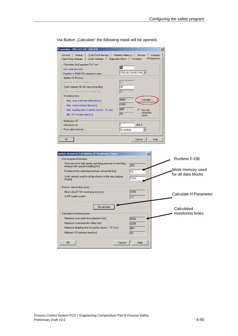
Configuring the safety program
Process Control System PCS 7 Engineering Compendium Part B Process Safety Preliminary Draft V2.0 4-45
Via Button „Calculate“ the following mask will be opened.
Runtime F-OB
Work memory used for all data blocks
Calculate H Parameter
Calculated monitoring times
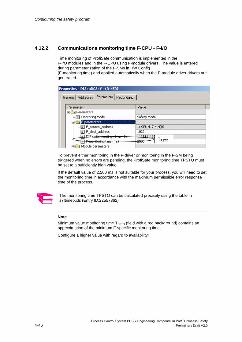
Configuring the safety program
Process Control System PCS 7 Engineering Compendium Part B Process Safety 4-46 Preliminary Draft V2.0
4.12.2 Communications monitoring time F-CPU - F-I/O
Time monitoring of ProfiSafe communication is implemented in the F-I/O modules and in the F-CPU using F-module drivers. The value is entered during parameterization of the F-SMs in HW Config (F-monitoring time) and applied automatically when the F-module driver drivers are generated.
To prevent either monitoring in the F-driver or monitoring in the F-SM being triggered when no errors are pending, the ProfiSafe monitoring time TPSTO must be set to a sufficiently high value.
If the default value of 2,500 ms is not suitable for your process, you will need to set the monitoring time in accordance with the maximum permissible error response time of the process.
The monitoring time TPSTO can be calculated precisely using the table in s7ftimeb.xls (Entry ID:22557362)
Note
Minimum value monitoring time TPSTO (field with a red background) contains an approximation of the minimum F-specific monitoring time.
Configure a higher value with regard to availability!
TPSTO
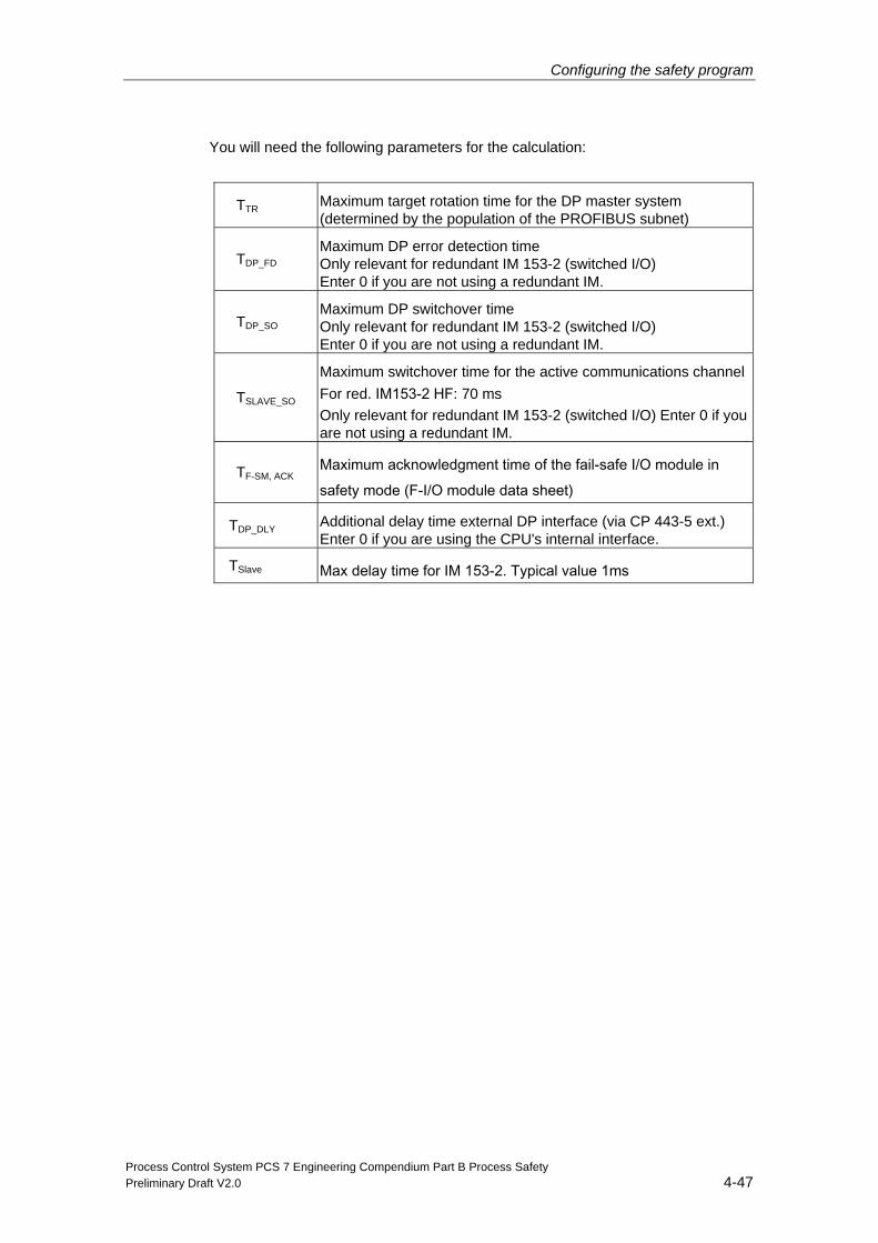
Configuring the safety program
Process Control System PCS 7 Engineering Compendium Part B Process Safety Preliminary Draft V2.0 4-47
You will need the following parameters for the calculation:
TTR Maximum target rotation time for the DP master system (determined by the population of the PROFIBUS subnet)
TDP_FD Maximum DP error detection time Only relevant for redundant IM 153-2 (switched I/O) Enter 0 if you are not using a redundant IM.
TDP_SO Maximum DP switchover time Only relevant for redundant IM 153-2 (switched I/O) Enter 0 if you are not using a redundant IM.
TSLAVE_SO
Maximum switchover time for the active communications channelFor red. IM153-2 HF: 70 ms Only relevant for redundant IM 153-2 (switched I/O) Enter 0 if you are not using a redundant IM.
TF-SM, ACK Maximum acknowledgment time of the fail-safe I/O module in safety mode (F-I/O module data sheet)
TDP_DLY Additional delay time external DP interface (via CP 443-5 ext.) Enter 0 if you are using the CPU's internal interface.
TSlave Max delay time for IM 153-2. Typical value 1ms
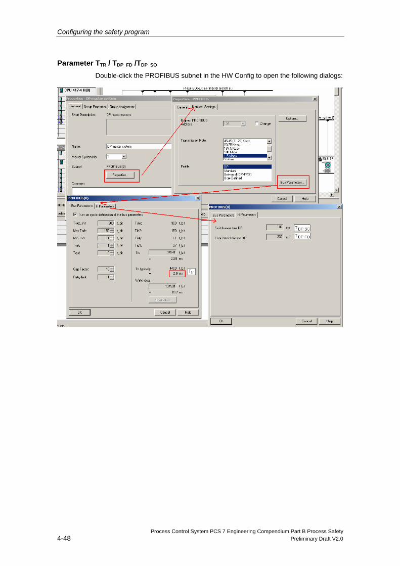
Configuring the safety program
Process Control System PCS 7 Engineering Compendium Part B Process Safety 4-48 Preliminary Draft V2.0
Parameter TTR / TDP_FD /TDP_SO Double-click the PROFIBUS subnet in the HW Config to open the following dialogs:
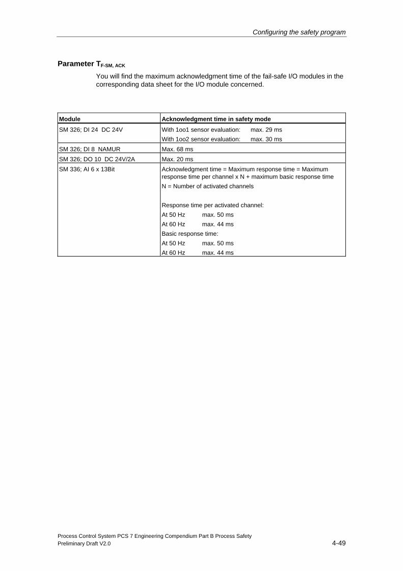
Configuring the safety program
Process Control System PCS 7 Engineering Compendium Part B Process Safety Preliminary Draft V2.0 4-49
Parameter TF-SM, ACK You will find the maximum acknowledgment time of the fail-safe I/O modules in the corresponding data sheet for the I/O module concerned.
Module Acknowledgment time in safety mode
SM 326; DI 24 DC 24V With 1oo1 sensor evaluation: max. 29 ms With 1oo2 sensor evaluation: max. 30 ms
SM 326; DI 8 NAMUR Max. 68 ms
SM 326; DO 10 DC 24V/2A Max. 20 ms
SM 336; AI 6 x 13Bit Acknowledgment time = Maximum response time = Maximum response time per channel x N + maximum basic response time N = Number of activated channels Response time per activated channel: At 50 Hz max. 50 ms At 60 Hz max. 44 ms Basic response time: At 50 Hz max. 50 ms At 60 Hz max. 44 ms
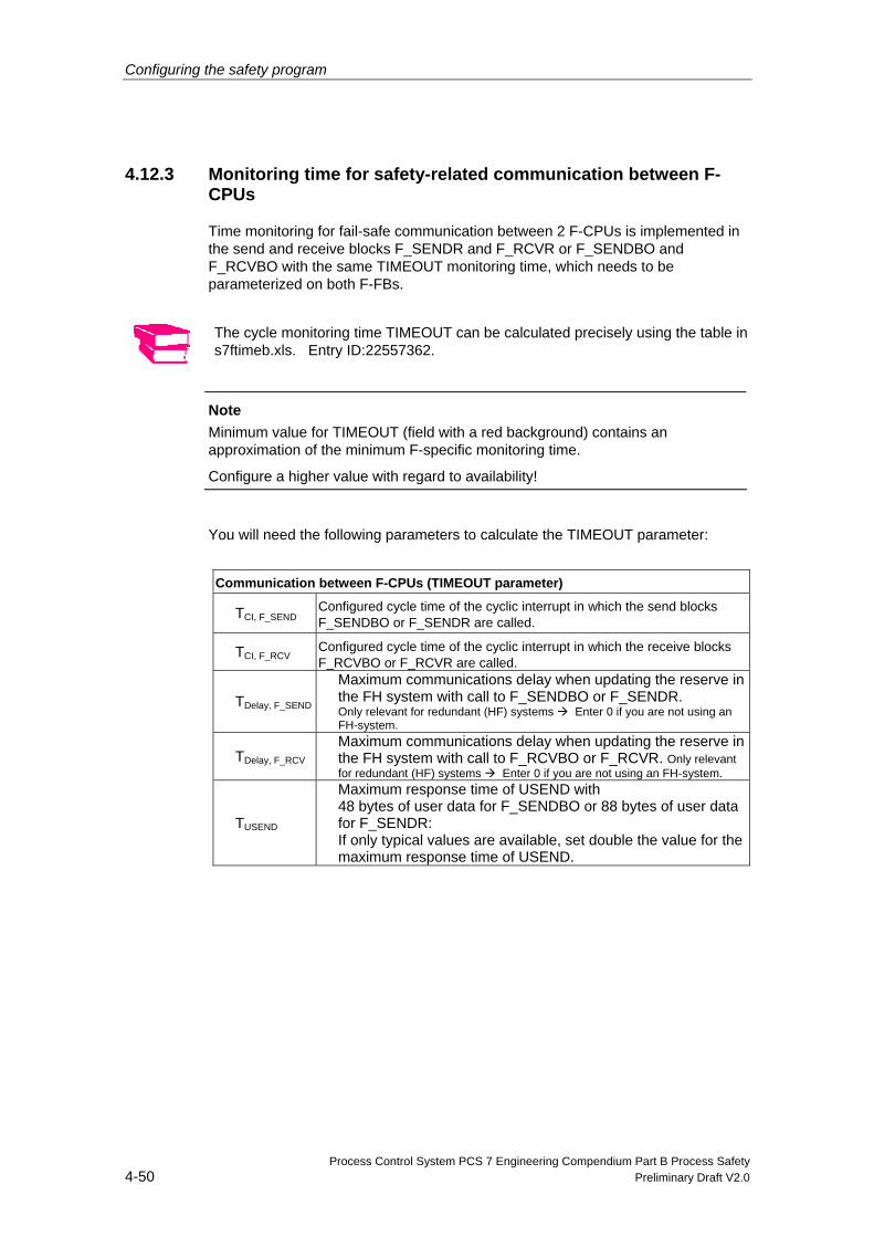
Configuring the safety program
Process Control System PCS 7 Engineering Compendium Part B Process Safety 4-50 Preliminary Draft V2.0
4.12.3 Monitoring time for safety-related communication between F-CPUs
Time monitoring for fail-safe communication between 2 F-CPUs is implemented in the send and receive blocks F_SENDR and F_RCVR or F_SENDBO and F_RCVBO with the same TIMEOUT monitoring time, which needs to be parameterized on both F-FBs.
The cycle monitoring time TIMEOUT can be calculated precisely using the table in s7ftimeb.xls. Entry ID:22557362.
Note
Minimum value for TIMEOUT (field with a red background) contains an approximation of the minimum F-specific monitoring time.
Configure a higher value with regard to availability!
You will need the following parameters to calculate the TIMEOUT parameter:
Communication between F-CPUs (TIMEOUT parameter)
TCI, F_SEND Configured cycle time of the cyclic interrupt in which the send blocks F_SENDBO or F_SENDR are called.
TCI, F_RCV Configured cycle time of the cyclic interrupt in which the receive blocks F_RCVBO or F_RCVR are called.
TDelay, F_SEND Maximum communications delay when updating the reserve in the FH system with call to F_SENDBO or F_SENDR. Only relevant for redundant (HF) systems Enter 0 if you are not using an FH-system.
TDelay, F_RCV Maximum communications delay when updating the reserve in the FH system with call to F_RCVBO or F_RCVR. Only relevant for redundant (HF) systems Enter 0 if you are not using an FH-system.
TUSEND
Maximum response time of USEND with 48 bytes of user data for F_SENDBO or 88 bytes of user data for F_SENDR: If only typical values are available, set double the value for the maximum response time of USEND.
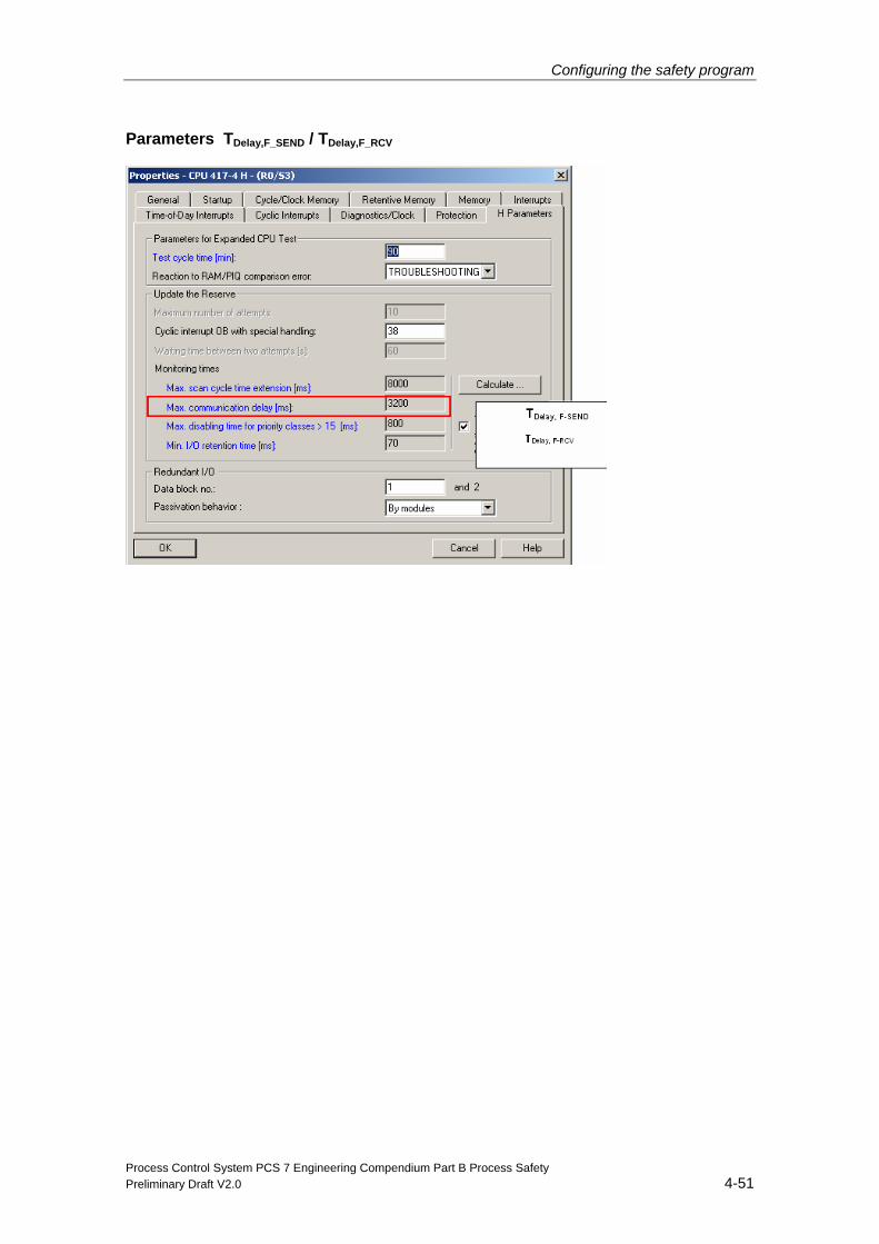
Configuring the safety program
Process Control System PCS 7 Engineering Compendium Part B Process Safety Preliminary Draft V2.0 4-51
Parameters TDelay,F_SEND / TDelay,F_RCV
Configuring the safety program
Process Control System PCS 7 Engineering Compendium Part B Process Safety 4-52 Preliminary Draft V2.0
4.12.4 Monitoring communication between F-shutdown groups
Time monitoring is implemented in the F_R_BO or F_R_R F-FBs and parameterized in these blocks' TIMEOUT input parameters.
To prevent time monitoring being triggered when no errors are pending, the TIMEOUT monitoring time must be set to a value which is at least equal to the higher of the two maximum cyclic interrupt cycle times of F_S_R or F_S_BO and F_R_R or F_R_BO.
The cycle monitoring time TIMEOUT can be calculated precisely using the table in s7ftimeb.xls. Entry ID:22557362.
Note
Minimum value for TIMEOUT (field with a red background) contains an approximation of the minimum F-specific monitoring time.
Configure a higher value with regard to availability!
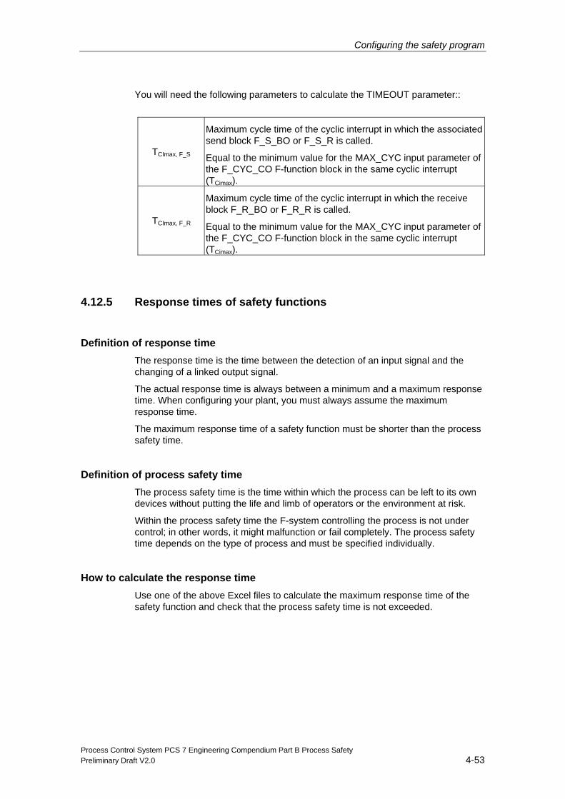
Configuring the safety program
Process Control System PCS 7 Engineering Compendium Part B Process Safety Preliminary Draft V2.0 4-53
You will need the following parameters to calculate the TIMEOUT parameter::
TCImax, F_S
Maximum cycle time of the cyclic interrupt in which the associated send block F_S_BO or F_S_R is called.
Equal to the minimum value for the MAX_CYC input parameter of the F_CYC_CO F-function block in the same cyclic interrupt (TCimax).
TCImax, F_R
Maximum cycle time of the cyclic interrupt in which the receive block F_R_BO or F_R_R is called.
Equal to the minimum value for the MAX_CYC input parameter of the F_CYC_CO F-function block in the same cyclic interrupt (TCimax).
4.12.5 Response times of safety functions
Definition of response time The response time is the time between the detection of an input signal and the changing of a linked output signal.
The actual response time is always between a minimum and a maximum response time. When configuring your plant, you must always assume the maximum response time.
The maximum response time of a safety function must be shorter than the process safety time.
Definition of process safety time The process safety time is the time within which the process can be left to its own devices without putting the life and limb of operators or the environment at risk.
Within the process safety time the F-system controlling the process is not under control; in other words, it might malfunction or fail completely. The process safety time depends on the type of process and must be specified individually.
How to calculate the response time Use one of the above Excel files to calculate the maximum response time of the safety function and check that the process safety time is not exceeded.
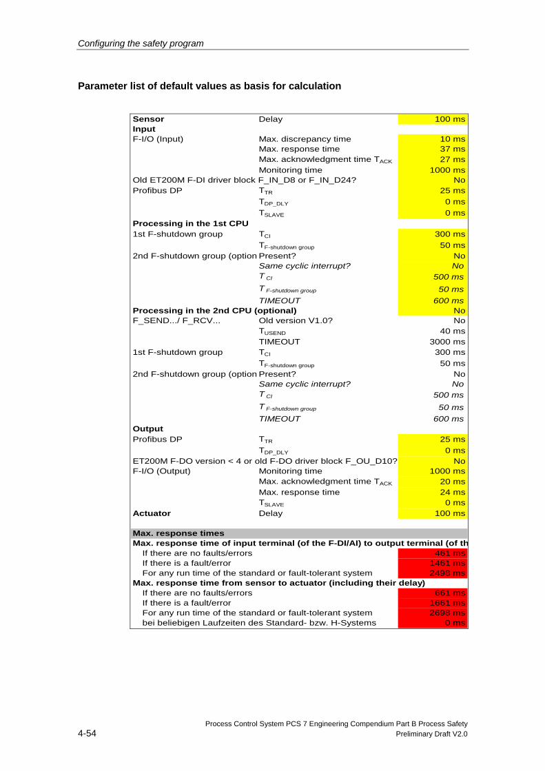
Configuring the safety program
Process Control System PCS 7 Engineering Compendium Part B Process Safety 4-54 Preliminary Draft V2.0
Parameter list of default values as basis for calculation
Sensor Delay 100 msInputF-I/O (Input) Max. discrepancy time 10 ms
Max. response time 37 msMax. acknowledgment time TACK 27 msMonitoring time 1000 ms
NoProfibus DP TTR 25 ms
TDP_DLY 0 msTSLAVE 0 ms
Processing in the 1st CPU1st F-shutdown group TCI 300 ms
TF-shutdown group 50 ms2nd F-shutdown group (option Present? No
Same cyclic interrupt? NoT CI 500 msT F-shutdown group 50 msTIMEOUT 600 ms
Processing in the 2nd CPU (optional) NoF_SEND.../ F_RCV... Old version V1.0? No
TUSEND 40 msTIMEOUT 3000 ms
1st F-shutdown group TCI 300 msTF-shutdown group 50 ms
2nd F-shutdown group (option Present? NoSame cyclic interrupt? NoT CI 500 msT F-shutdown group 50 msTIMEOUT 600 ms
OutputProfibus DP TTR 25 ms
TDP_DLY 0 msNo
F-I/O (Output) Monitoring time 1000 msMax. acknowledgment time TACK 20 msMax. response time 24 msTSLAVE 0 ms
Actuator Delay 100 ms
Max. response timesMax. response time of input terminal (of the F-DI/AI) to output terminal (of th
If there are no faults/errors 461 msIf there is a fault/error 1461 msFor any run time of the standard or fault-tolerant system 2498 ms
Max. response time from sensor to actuator (including their delay)If there are no faults/errors 661 msIf there is a fault/error 1661 msFor any run time of the standard or fault-tolerant system 2698 msbei beliebigen Laufzeiten des Standard- bzw. H-Systems 0 ms
Old ET200M F-DI driver block F_IN_D8 or F_IN_D24?
ET200M F-DO version < 4 or old F-DO driver block F_OU_D10?
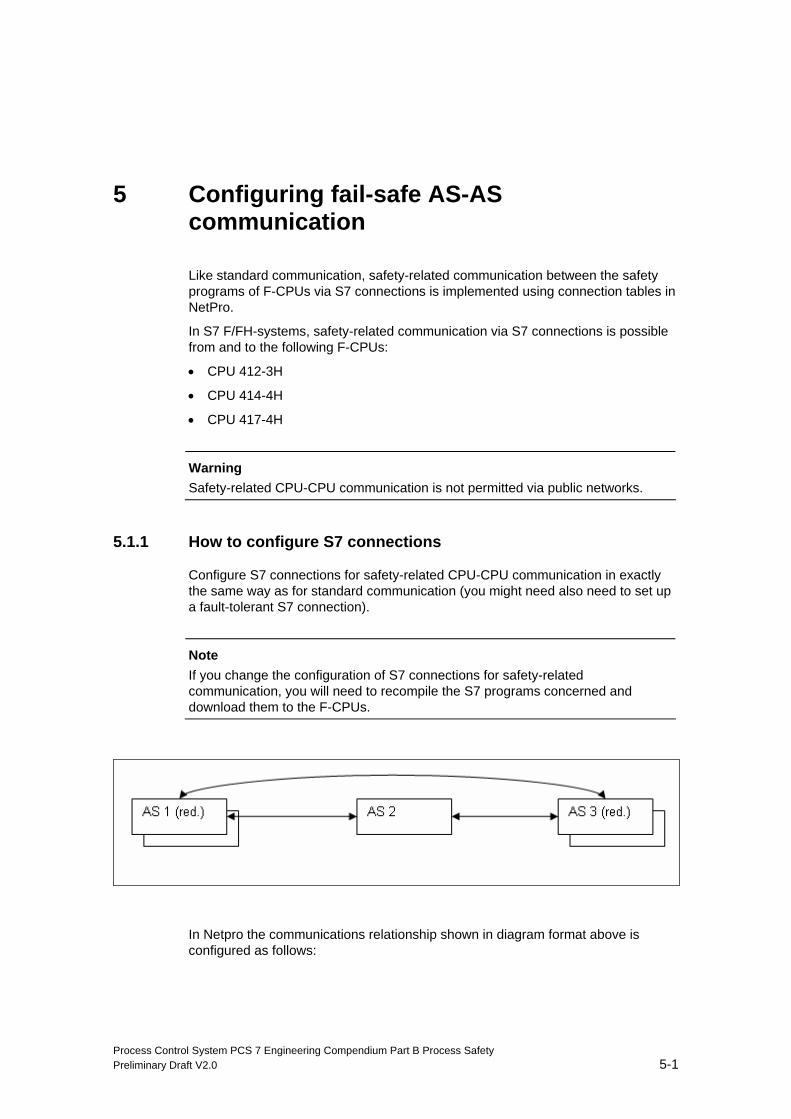
Process Control System PCS 7 Engineering Compendium Part B Process Safety Preliminary Draft V2.0 5-1
5 Configuring fail-safe AS-AS communication
Like standard communication, safety-related communication between the safety programs of F-CPUs via S7 connections is implemented using connection tables in NetPro.
In S7 F/FH-systems, safety-related communication via S7 connections is possible from and to the following F-CPUs:
• CPU 412-3H
• CPU 414-4H
• CPU 417-4H
Warning
Safety-related CPU-CPU communication is not permitted via public networks.
5.1.1 How to configure S7 connections
Configure S7 connections for safety-related CPU-CPU communication in exactly the same way as for standard communication (you might need also need to set up a fault-tolerant S7 connection).
Note
If you change the configuration of S7 connections for safety-related communication, you will need to recompile the S7 programs concerned and download them to the F-CPUs.
In Netpro the communications relationship shown in diagram format above is configured as follows:
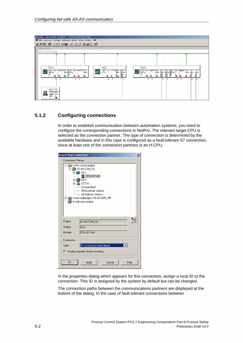
Configuring fail-safe AS-AS communication
Process Control System PCS 7 Engineering Compendium Part B Process Safety 5-2 Preliminary Draft V2.0
5.1.2 Configuring connections
In order to establish communication between automation systems, you need to configure the corresponding connections in NetPro. The relevant target CPU is selected as the connection partner. The type of connection is determined by the available hardware and in this case is configured as a fault-tolerant S7 connection, since at least one of the connection partners is an H-CPU.
In the properties dialog which appears for this connection, assign a local ID to the connection. This ID is assigned by the system by default but can be changed.
The connection paths between the communications partners are displayed at the bottom of the dialog. In the case of fault-tolerant connections between
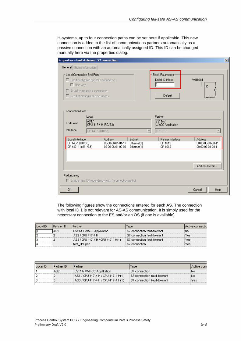
Configuring fail-safe AS-AS communication
Process Control System PCS 7 Engineering Compendium Part B Process Safety Preliminary Draft V2.0 5-3
H-systems, up to four connection paths can be set here if applicable. This new connection is added to the list of communications partners automatically as a passive connection with an automatically assigned ID. This ID can be changed manually here via the properties dialog.
The following figures show the connections entered for each AS. The connection with local ID 1 is not relevant for AS-AS communication. It is simply used for the necessary connection to the ES and/or an OS (if one is available).
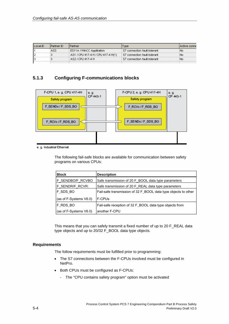
Configuring fail-safe AS-AS communication
Process Control System PCS 7 Engineering Compendium Part B Process Safety 5-4 Preliminary Draft V2.0
5.1.3 Configuring F-communications blocks
The following fail-safe blocks are available for communication between safety programs on various CPUs:
Block Description
F_SENDBO/F_RCVBO Safe transmission of 20 F_BOOL data type parameters
F_SENDR/F_RCVR: Safe transmission of 20 F_REAL data type parameters F_SDS_BO
(as of F-Systems V6.0)
Fail-safe transmission of 32 F_BOOL data type objects to other
F-CPUs
F_RDS_BO (as of F-Systems V6.0)
Fail-safe reception of 32 F_BOOL data type objects from
another F-CPU
This means that you can safely transmit a fixed number of up to 20 F_REAL data type objects and up to 20/32 F_BOOL data type objects.
Requirements The follow requirements must be fulfilled prior to programming:
• The S7 connections between the F-CPUs involved must be configured in NetPro.
• Both CPUs must be configured as F-CPUs:
- The "CPU contains safety program" option must be activated
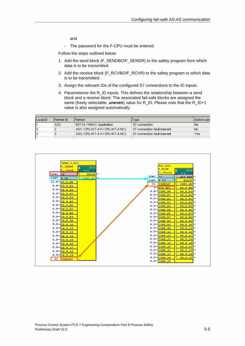
Configuring fail-safe AS-AS communication
Process Control System PCS 7 Engineering Compendium Part B Process Safety Preliminary Draft V2.0 5-5
and
- The password for the F-CPU must be entered.
Follow the steps outlined below:
1. Add the send block (F_SENDBO/F_SENDR) to the safety program from which data is to be transmitted.
2. Add the receive block (F_RCVBO/F_RCVR) to the safety program to which data is to be transmitted.
3. Assign the relevant IDs of the configured S7 connections to the ID inputs.
4. Parameterize the R_ID inputs. This defines the relationship between a send block and a receive block: The associated fail-safe blocks are assigned the same (freely selectable, uneven) value for R_ID. Please note that the R_ID+1 value is also assigned automatically.
Configuring fail-safe AS-AS communication
Process Control System PCS 7 Engineering Compendium Part B Process Safety 5-6 Preliminary Draft V2.0
Note If the R_ID is not an uneven number, the following error message will appear when the CFC charts are compiled:
"Module/connection with address/R_ID 16#0002/16#00000004 is being used by more than one block. [Assign a module/connection with this address/R_ID to no more than one block and use only uneven R_IDs.]"
5. Interconnect the ACK_NEC outputs of the F_RCVBO or F_RCVR F-blocks in order to ascertain whether acknowledgment is required on reintegration following error elimination.
6. Interconnect the relevant ACK_REI inputs of the F_RCVBO or F_RCVR F-blocks with the signal for acknowledging reintegration.
Safety instruction
You must recompile the safety program in the event of changes to the S7 connections for communication between CPUs.
User acknowledgment is always required for reintegration following PROFIsafe communications errors (ACK_REQ output set), even if ACK_NEC has not been set.
The communications load can be reduced if communications blocks are not processed unnecessarily in fast OBs. For example, communications blocks could be processed in OB32 (1 ms) while faster F-program parts run in a faster OB35 (100 ms). If the process permits, the timeout time should also be set as high as possible (e.g. 10 s). If the maximum communications load of a system is for example 100 jobs per second, this would represent a total of 20 communications jobs with 10 F_RECVX and 10 F_SENDX-B blocks. If these are configured in OB32 (1 ms), this corresponds to a communications load of 20% based on the above assumption of 100 jobs per second. Integrating these blocks in OB35 (100 ms) would increase the communications load.
Process Control System PCS 7 Engineering Compendium Part B Process Safety Preliminary Draft V2.0 6-1
6 Configuring F-block types
6.1 Rules for F-block types
The basic procedure for creating a new F-block type is the same as in the standard user program. The same rules apply as for creating block types in CFC. Please also note:
• The new F-block type can only contain F-blocks from the F-library, with the following exceptions:
- F-channel drivers for F-I/Os
- F-blocks for F-communication
- The F_CHG_BO, F_CHG_R or F_MOV_R F-blocks
- All F-monitoring blocks
- All F-system blocks with the exception of F_START
• The F-blocks called in the new F-block type, as well as all F-blocks in the safety program in which the F-block type is being used, must come from the same library version. F-blocks from different versions of the F-library are not permitted.
• You are not permitted to connect one F-block output to two chart I/Os.
• Within an F-block type, the run sequence is not corrected automatically during compilation. The sequence defined on creation is retained.
Note
If the sequence differs from the data flow, for example due to feedback, compilation of the F-block type will be aborted with an error.
• The chart I/Os of the new F-block type can have both F-data types and standard data types.
• You are not permitted to use the names of F-blocks in the F-library for the names of F-block types.
• We recommend assigning names for instances of F-blocks called in a single F-block type as follows:
- Numbers only as per the CFC editor default or alphanumeric names (but these must always start with F_)
- Uppercase letters only without "_" at the end
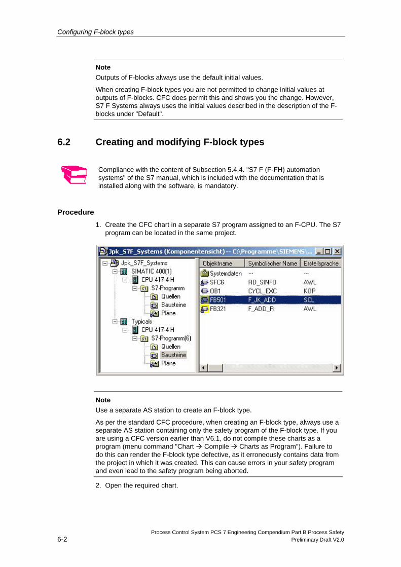
Configuring F-block types
Process Control System PCS 7 Engineering Compendium Part B Process Safety 6-2 Preliminary Draft V2.0
Note Outputs of F-blocks always use the default initial values.
When creating F-block types you are not permitted to change initial values at outputs of F-blocks. CFC does permit this and shows you the change. However, S7 F Systems always uses the initial values described in the description of the F-blocks under "Default".
6.2 Creating and modifying F-block types
Compliance with the content of Subsection 5.4.4. "S7 F (F-FH) automation systems" of the S7 manual, which is included with the documentation that is installed along with the software, is mandatory.
Procedure 1. Create the CFC chart in a separate S7 program assigned to an F-CPU. The S7
program can be located in the same project.
Note
Use a separate AS station to create an F-block type.
As per the standard CFC procedure, when creating an F-block type, always use a separate AS station containing only the safety program of the F-block type. If you are using a CFC version earlier than V6.1, do not compile these charts as a program (menu command "Chart Compile Charts as Program"). Failure to do this can render the F-block type defective, as it erroneously contains data from the project in which it was created. This can cause errors in your safety program and even lead to the safety program being aborted.
2. Open the required chart.
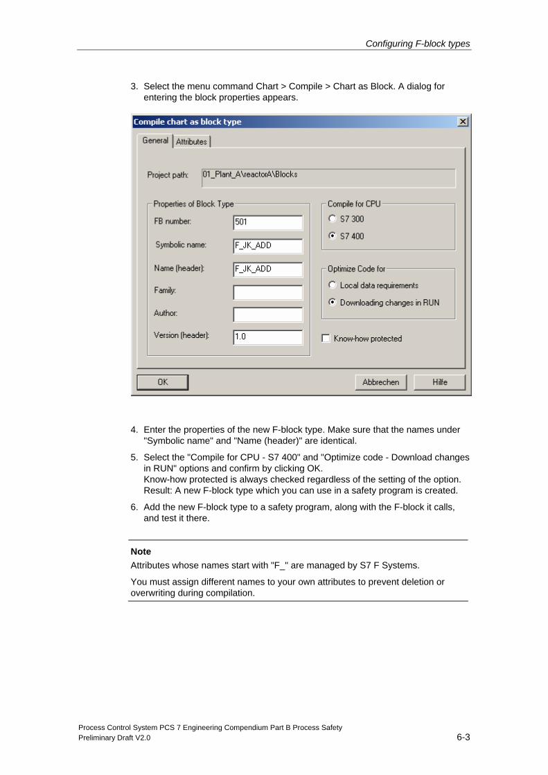
Configuring F-block types
Process Control System PCS 7 Engineering Compendium Part B Process Safety Preliminary Draft V2.0 6-3
3. Select the menu command Chart > Compile > Chart as Block. A dialog for entering the block properties appears.
4. Enter the properties of the new F-block type. Make sure that the names under "Symbolic name" and "Name (header)" are identical.
5. Select the "Compile for CPU - S7 400" and "Optimize code - Download changes in RUN" options and confirm by clicking OK. Know-how protected is always checked regardless of the setting of the option. Result: A new F-block type which you can use in a safety program is created.
6. Add the new F-block type to a safety program, along with the F-block it calls, and test it there.
Note
Attributes whose names start with "F_" are managed by S7 F Systems.
You must assign different names to your own attributes to prevent deletion or overwriting during compilation.
Configuring F-block types
Process Control System PCS 7 Engineering Compendium Part B Process Safety 6-4 Preliminary Draft V2.0
Modifying F-block types You must update modified F-block types in the CFC editor in the same way as all other block types. To do this, open the "Block Types" dialog with the menu command "Options Block Types" and click "New version".
Making changes to F-block types which have already been used can mean that you need to subsequently compile and download the entire S7 program.
If you wish to use a new version of the F-library, you must compile the F-block types with this new version of the F-library.
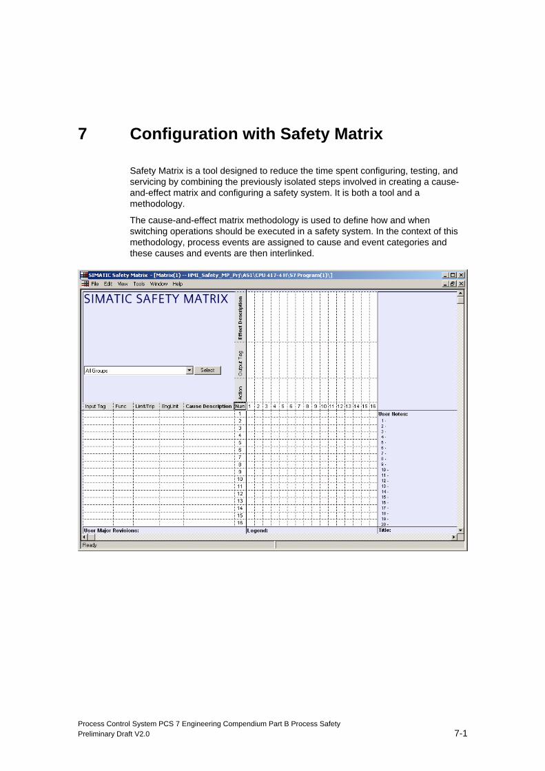
Process Control System PCS 7 Engineering Compendium Part B Process Safety Preliminary Draft V2.0 7-1
7 Configuration with Safety Matrix
Safety Matrix is a tool designed to reduce the time spent configuring, testing, and servicing by combining the previously isolated steps involved in creating a cause-and-effect matrix and configuring a safety system. It is both a tool and a methodology.
The cause-and-effect matrix methodology is used to define how and when switching operations should be executed in a safety system. In the context of this methodology, process events are assigned to cause and event categories and these causes and events are then interlinked.
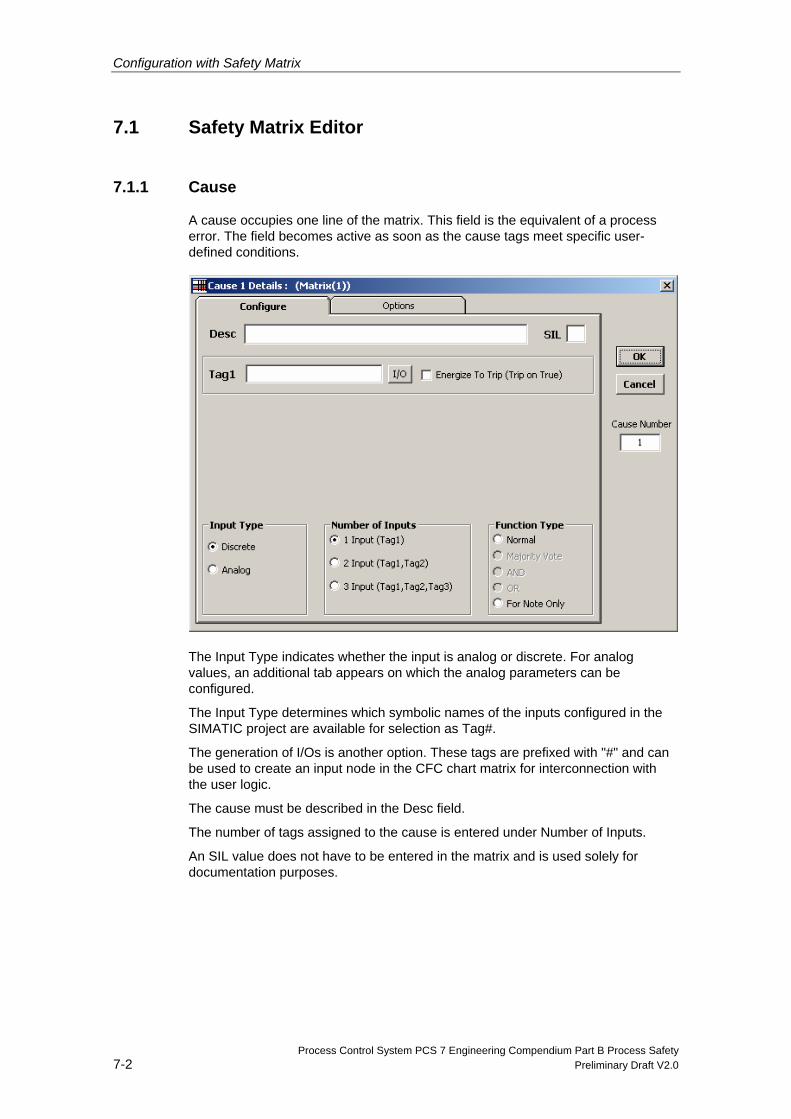
Configuration with Safety Matrix
Process Control System PCS 7 Engineering Compendium Part B Process Safety 7-2 Preliminary Draft V2.0
7.1 Safety Matrix Editor
7.1.1 Cause
A cause occupies one line of the matrix. This field is the equivalent of a process error. The field becomes active as soon as the cause tags meet specific user-defined conditions.
The Input Type indicates whether the input is analog or discrete. For analog values, an additional tab appears on which the analog parameters can be configured.
The Input Type determines which symbolic names of the inputs configured in the SIMATIC project are available for selection as Tag#.
The generation of I/Os is another option. These tags are prefixed with "#" and can be used to create an input node in the CFC chart matrix for interconnection with the user logic.
The cause must be described in the Desc field.
The number of tags assigned to the cause is entered under Number of Inputs.
An SIL value does not have to be entered in the matrix and is used solely for documentation purposes.
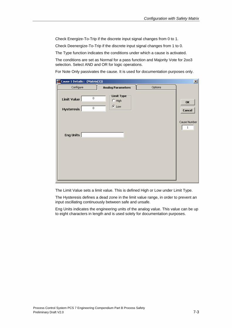
Configuration with Safety Matrix
Process Control System PCS 7 Engineering Compendium Part B Process Safety Preliminary Draft V2.0 7-3
Check Energize-To-Trip if the discrete input signal changes from 0 to 1.
Check Deenergize-To-Trip if the discrete input signal changes from 1 to 0.
The Type function indicates the conditions under which a cause is activated.
The conditions are set as Normal for a pass function and Majority Vote for 2oo3 selection. Select AND and OR for logic operations.
For Note Only passivates the cause. It is used for documentation purposes only.
The Limit Value sets a limit value. This is defined High or Low under Limit Type.
The Hysteresis defines a dead zone in the limit value range, in order to prevent an input oscillating continuously between safe and unsafe.
Eng Units indicates the engineering units of the analog value. This value can be up to eight characters in length and is used solely for documentation purposes.
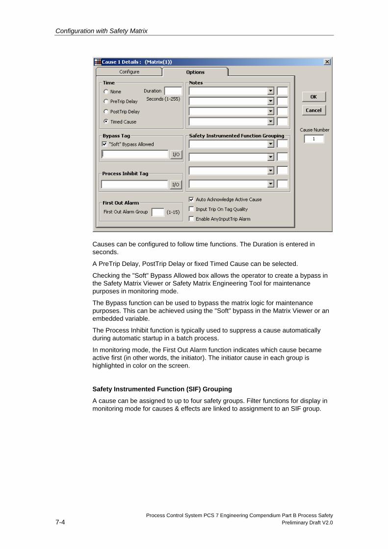
Configuration with Safety Matrix
Process Control System PCS 7 Engineering Compendium Part B Process Safety 7-4 Preliminary Draft V2.0
Causes can be configured to follow time functions. The Duration is entered in seconds.
A PreTrip Delay, PostTrip Delay or fixed Timed Cause can be selected.
Checking the "Soft" Bypass Allowed box allows the operator to create a bypass in the Safety Matrix Viewer or Safety Matrix Engineering Tool for maintenance purposes in monitoring mode.
The Bypass function can be used to bypass the matrix logic for maintenance purposes. This can be achieved using the "Soft" bypass in the Matrix Viewer or an embedded variable.
The Process Inhibit function is typically used to suppress a cause automatically during automatic startup in a batch process.
In monitoring mode, the First Out Alarm function indicates which cause became active first (in other words, the initiator). The initiator cause in each group is highlighted in color on the screen.
Safety Instrumented Function (SIF) Grouping
A cause can be assigned to up to four safety groups. Filter functions for display in monitoring mode for causes & effects are linked to assignment to an SIF group.
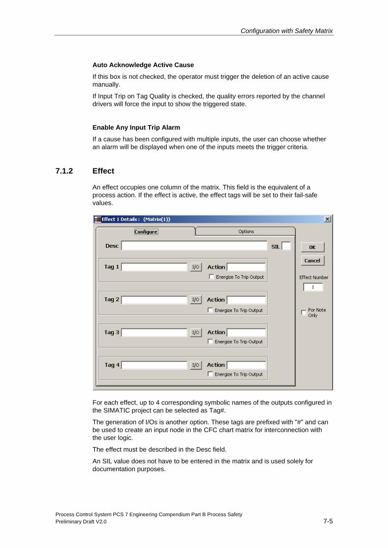
Configuration with Safety Matrix
Process Control System PCS 7 Engineering Compendium Part B Process Safety Preliminary Draft V2.0 7-5
Auto Acknowledge Active Cause
If this box is not checked, the operator must trigger the deletion of an active cause manually.
If Input Trip on Tag Quality is checked, the quality errors reported by the channel drivers will force the input to show the triggered state.
Enable Any Input Trip Alarm
If a cause has been configured with multiple inputs, the user can choose whether an alarm will be displayed when one of the inputs meets the trigger criteria.
7.1.2 Effect
An effect occupies one column of the matrix. This field is the equivalent of a process action. If the effect is active, the effect tags will be set to their fail-safe values.
For each effect, up to 4 corresponding symbolic names of the outputs configured in the SIMATIC project can be selected as Tag#.
The generation of I/Os is another option. These tags are prefixed with "#" and can be used to create an input node in the CFC chart matrix for interconnection with the user logic.
The effect must be described in the Desc field.
An SIL value does not have to be entered in the matrix and is used solely for documentation purposes.
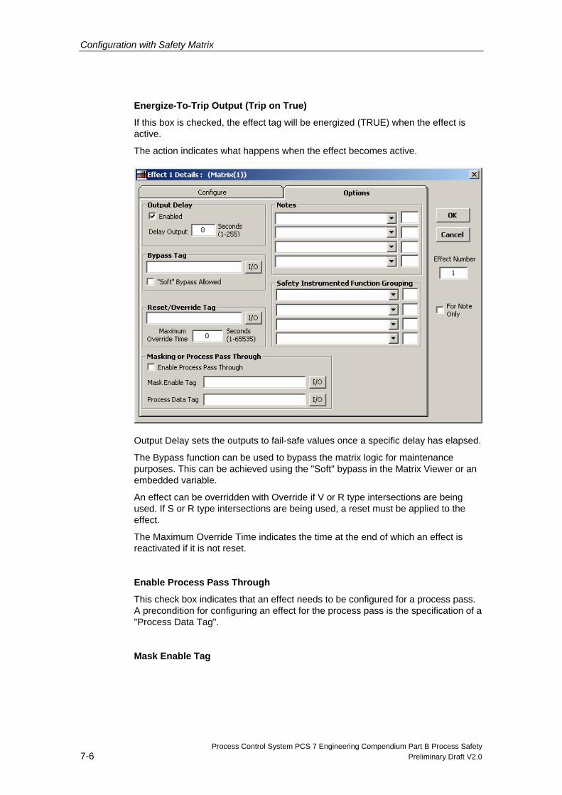
Configuration with Safety Matrix
Process Control System PCS 7 Engineering Compendium Part B Process Safety 7-6 Preliminary Draft V2.0
Energize-To-Trip Output (Trip on True)
If this box is checked, the effect tag will be energized (TRUE) when the effect is active.
The action indicates what happens when the effect becomes active.
Output Delay sets the outputs to fail-safe values once a specific delay has elapsed.
The Bypass function can be used to bypass the matrix logic for maintenance purposes. This can be achieved using the "Soft" bypass in the Matrix Viewer or an embedded variable.
An effect can be overridden with Override if V or R type intersections are being used. If S or R type intersections are being used, a reset must be applied to the effect.
The Maximum Override Time indicates the time at the end of which an effect is reactivated if it is not reset.
Enable Process Pass Through
This check box indicates that an effect needs to be configured for a process pass. A precondition for configuring an effect for the process pass is the specification of a "Process Data Tag".
Mask Enable Tag
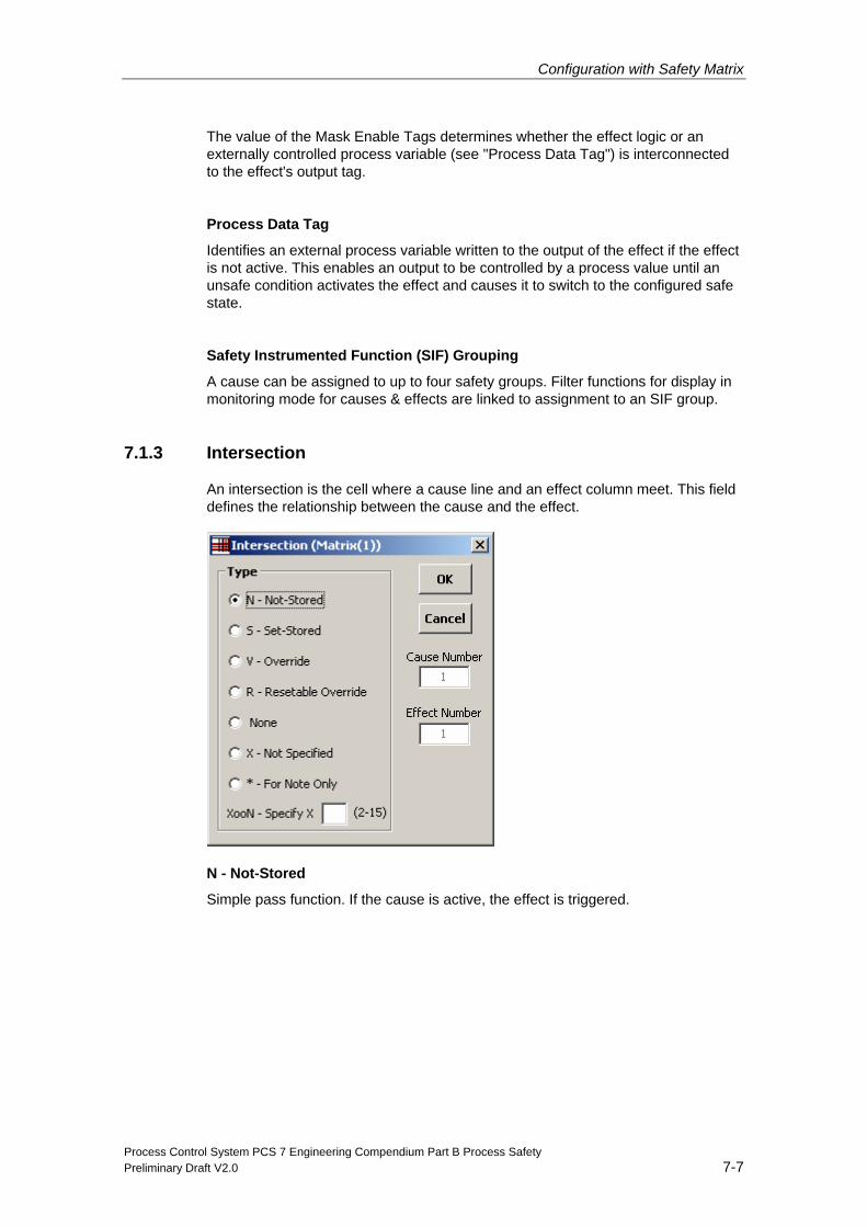
Configuration with Safety Matrix
Process Control System PCS 7 Engineering Compendium Part B Process Safety Preliminary Draft V2.0 7-7
The value of the Mask Enable Tags determines whether the effect logic or an externally controlled process variable (see "Process Data Tag") is interconnected to the effect's output tag.
Process Data Tag
Identifies an external process variable written to the output of the effect if the effect is not active. This enables an output to be controlled by a process value until an unsafe condition activates the effect and causes it to switch to the configured safe state.
Safety Instrumented Function (SIF) Grouping
A cause can be assigned to up to four safety groups. Filter functions for display in monitoring mode for causes & effects are linked to assignment to an SIF group.
7.1.3 Intersection
An intersection is the cell where a cause line and an effect column meet. This field defines the relationship between the cause and the effect.
N - Not-Stored
Simple pass function. If the cause is active, the effect is triggered.
Configuration with Safety Matrix
Process Control System PCS 7 Engineering Compendium Part B Process Safety 7-8 Preliminary Draft V2.0
S - Set-Stored
If the cause is active, the effect is triggered and saved (interlocked). If the effect is no longer triggered, it must be deleted by the operator by means of manual intervention or by setting the configured reset/override tag to TRUE.
V - Override
If the cause is active, the effect is triggered. The effect can be overridden by the operator by means of manual intervention or by setting the configured reset/override tag to TRUE (as long as the effect is still triggered). This permits the user to reintegrate his or her system if the effect output stops a cause in the active state.
R - Resettable Override
This intersection type links the S and V types described above. The effects interconnected with this intersection remain interlocked if the corresponding cause is deactivated but can be bypassed with the override function.
None
There is no link between this cause and this effect (no entry at the intersection). This is the default intersection type.
X - Not Specified
A link is required between the cause and the effect but the required intersection type has not yet been defined. No link will be processed until the intersection type has been entered. A matrix with intersection type X cannot be transmitted to the controller.
* - For Note Only
No link will be processed between this cause and this effect. For documentation purposes only.
XooN – Specify X___(2-15)
This enables causes to be assigned in accordance with the majority vote procedure. X is entered by the user, N is determined from the number of intersections with X as a coefficient. Only one XooN assignment is permitted for each effect. Only intersections of the same type (all S or all N intersections, for example) can be taken into account where assignment in accordance with the majority vote principle is concerned. The figure below illustrates examples of this type of intersection assignment.
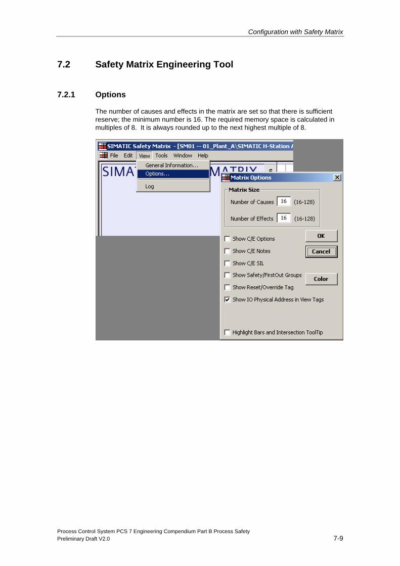
Configuration with Safety Matrix
Process Control System PCS 7 Engineering Compendium Part B Process Safety Preliminary Draft V2.0 7-9
7.2 Safety Matrix Engineering Tool
7.2.1 Options
The number of causes and effects in the matrix are set so that there is sufficient reserve; the minimum number is 16. The required memory space is calculated in multiples of 8. It is always rounded up to the next highest multiple of 8.
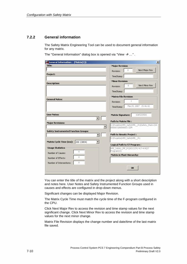
Configuration with Safety Matrix
Process Control System PCS 7 Engineering Compendium Part B Process Safety 7-10 Preliminary Draft V2.0
7.2.2 General information
The Safety Matrix Engineering Tool can be used to document general information for any matrix.
The "General Information" dialog box is opened via "View …" .
You can enter the title of the matrix and the project along with a short description and notes here. User Notes and Safety Instrumented Function Groups used in causes and effects are configured in drop-down menus.
Significant changes can be displayed Major Revision.
The Matrix Cycle Time must match the cycle time of the F-program configured in the CPU.
Click Next Major Rev to access the revision and time stamp values for the next significant change. Click Next Minor Rev to access the revision and time stamp values for the next minor change.
Matrix File Revision displays the change number and date/time of the last matrix file saved.
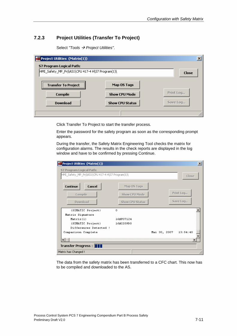
Configuration with Safety Matrix
Process Control System PCS 7 Engineering Compendium Part B Process Safety Preliminary Draft V2.0 7-11
7.2.3 Project Utilities (Transfer To Project)
Select "Tools Project Utilities".
Click Transfer To Project to start the transfer process.
Enter the password for the safety program as soon as the corresponding prompt appears.
During the transfer, the Safety Matrix Engineering Tool checks the matrix for configuration alarms. The results in the check reports are displayed in the log window and have to be confirmed by pressing Continue.
The data from the safety matrix has been transferred to a CFC chart. This now has to be compiled and downloaded to the AS.
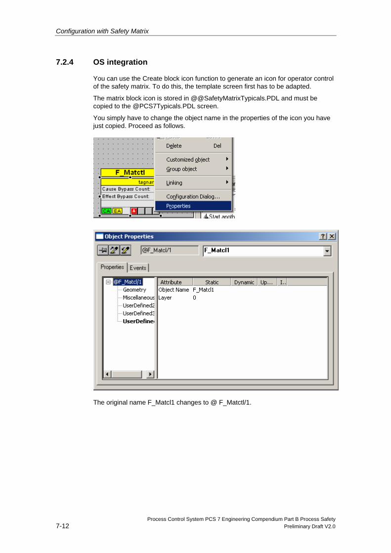
Configuration with Safety Matrix
Process Control System PCS 7 Engineering Compendium Part B Process Safety 7-12 Preliminary Draft V2.0
7.2.4 OS integration
You can use the Create block icon function to generate an icon for operator control of the safety matrix. To do this, the template screen first has to be adapted.
The matrix block icon is stored in @@SafetyMatrixTypicals.PDL and must be copied to the @PCS7Typicals.PDL screen.
You simply have to change the object name in the properties of the icon you have just copied. Proceed as follows.
The original name F_Matcl1 changes to @ F_Matctl/1.
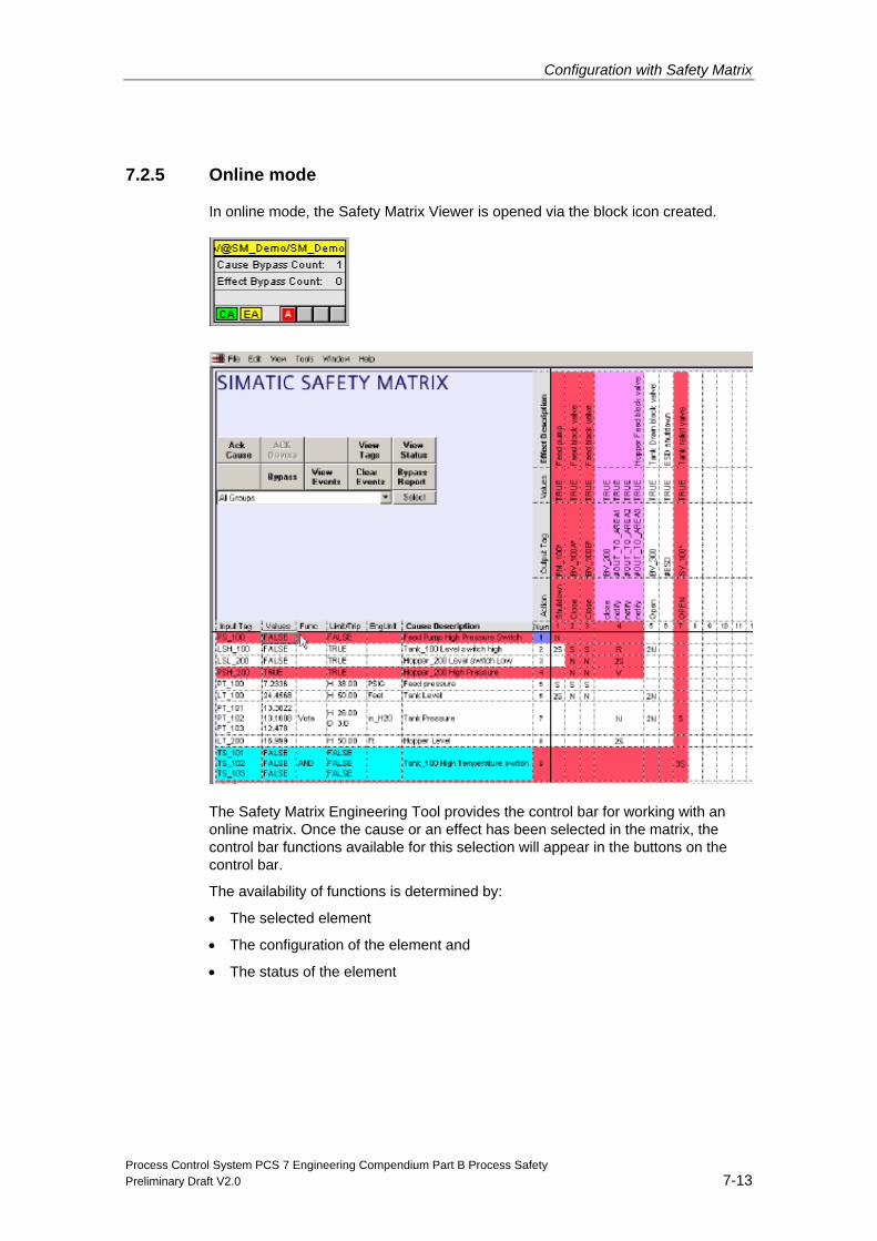
Configuration with Safety Matrix
Process Control System PCS 7 Engineering Compendium Part B Process Safety Preliminary Draft V2.0 7-13
7.2.5 Online mode
In online mode, the Safety Matrix Viewer is opened via the block icon created.
The Safety Matrix Engineering Tool provides the control bar for working with an online matrix. Once the cause or an effect has been selected in the matrix, the control bar functions available for this selection will appear in the buttons on the control bar.
The availability of functions is determined by:
• The selected element
• The configuration of the element and
• The status of the element
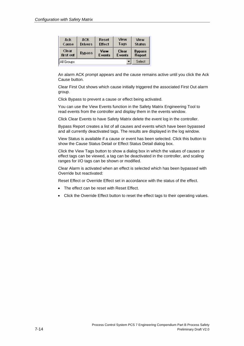
Configuration with Safety Matrix
Process Control System PCS 7 Engineering Compendium Part B Process Safety 7-14 Preliminary Draft V2.0
An alarm ACK prompt appears and the cause remains active until you click the Ack Cause button.
Clear First Out shows which cause initially triggered the associated First Out alarm group.
Click Bypass to prevent a cause or effect being activated.
You can use the View Events function in the Safety Matrix Engineering Tool to read events from the controller and display them in the events window.
Click Clear Events to have Safety Matrix delete the event log in the controller.
Bypass Report creates a list of all causes and events which have been bypassed and all currently deactivated tags. The results are displayed in the log window.
View Status is available if a cause or event has been selected. Click this button to show the Cause Status Detail or Effect Status Detail dialog box.
Click the View Tags button to show a dialog box in which the values of causes or effect tags can be viewed, a tag can be deactivated in the controller, and scaling ranges for I/O tags can be shown or modified.
Clear Alarm is activated when an effect is selected which has been bypassed with Override but reactivated:
Reset Effect or Override Effect set in accordance with the status of the effect.
• The effect can be reset with Reset Effect.
• Click the Override Effect button to reset the effect tags to their operating values.

Configuration with Safety Matrix
Process Control System PCS 7 Engineering Compendium Part B Process Safety Preliminary Draft V2.0 7-15
7.2.6 Status display
When Safety Matrix is in monitoring mode, the status of causes, intersections, and effects is displayed in various colors. These colors are fixed and cannot be changed by the user.
Red Cause/Effect Active
Magenta Bypass Active or Tag Disabled
Yellow Inhibit/Mask Active
Brown Effect Override Active
Green Safe to Reset Effect
Cyan First Out Alarm Active
Blue Click the View Status button

Process Control System PCS 7 Engineering Compendium Part B Process Safety Preliminary Draft V2.0 8-1
8 System Acceptance Test
8.1 Overview of system acceptance test
During the system acceptance test, all relevant application-specific standards must be adhered to as well as the following procedures. This also applies to systems that are not subject to acceptance testing. For acceptance testing, you must note the systems requiring approval in the Certification Report.
As a general rule, the acceptance test of an F-System is performed by independent experts. Special functions in SIMATIC Manager assist you for the acceptance test of an F-System. You can use these functions to:
• Compare safety programs
• Log safety programs
• Print safety programs
8.2 Commissioning a safety program
General procedure for the initial acceptance test of a safety program
1. Preliminary test of the configuration of the
2. Backup of the STEP 7 project
3. Inspection of the printout
4. Downloading the S7 program to the F-CPU
5. Implementation of a complete function test
8.2.2 Preliminary test of the configuration of the F-CPU and F-I/O (optional)
After you finish configuring the hardware and assigning parameters for the F-CPU and F-I/O, you can perform an initial acceptance test for the F-I/O configuration.In order to do this, the hardware configuration data must be printed out, checked, and saved together with the overall STEP 7 project.
System Acceptance Test
Process Control System PCS 7 Engineering Compendium Part B Process Safety 8-2 Preliminary Draft V2.0
8.2.3 Printing hardware configuration data
1. Select the correct F-CPU or S7 program assigned to it.
2. In SIMATIC Manager, select the Options > Edit Safety Program menu command. The "Safety Program" dialog will appear.
3. Click the "Print" button and select the "HW Configuration" option in the next dialog:
4. Select "All" for the print range, and select the "Module description" and "Address list" options there. In addition, select the "Including parameter description" option to include your parameter descriptions in the printout.
8.2.4 Checking hardware configuration data
1. Check the parameters of the F-CPU in the printout. In safety mode, access by means of the F-CPU password must not be authorized when making changes to the standard user program, since changes to the safety program can also be made. To rule out this possibility, you must configure Protection Level 1. In addition, you must select the "CPU contains safety program" option. The corresponding protection level and "CPU contains safety program" is included in the printout.
2. Check the safety-related parameters of the F-I/O in the printout. These safety-related parameters can be found in the printout for the respective F-I/O. The data are structured differently according to the F-I/O as follows:
SM 326; DI 24 x DC 24 V (Order No. 6ES7326-1BK00-0AB0), SM 326; DI 8 x Namur, SM 326; DO 10 x DC 24V/2A, SM 336; AI 6 x13 Bit
- The PROFIsafe source address does not appear in the printout.
- You determine the PROFIsafe destination address from the address value under "Addresses – Inputs – Start". Divide this address value by "8".
- The safety-related parameters are found under "Parameters – Basic
Settings" or "Parameters – Input/Output x".
ET200S, ET 200pro, ET 200eco fail-safe modules, SM 326; DI 24 x DC 24 V (as of Order No. 6ES7326-1BK01-0AB0) and SM 326; DO 8 x DC 24V/2A PM
- The PROFIsafe source address is found under "Parameters – F-
Parameters – F_Source_Address".
- The PROFIsafe destination address is found under "Parameters – F-
Parameters – F_destination_address".
- The safety-related parameters are found under "Parameters – F-
Parameters" and "Parameters – Module parameters".
System Acceptance Test
Process Control System PCS 7 Engineering Compendium Part B Process Safety Preliminary Draft V2.0 8-3
Failsafe DP standard slaves
- The PROFIsafe source address is found under "PROFIsafe – F_Source_Add".
- The PROFIsafe destination address is found under "PROFIsafe – F_Dest_Add".
- The safety-related parameters are found under "PROFIsafe".
For information on handling of any process- and safety-related parameters, refer to the documentation for the respective DP standard slave.
3. Once the safety-related parameters of an F-I/O module are checked, the parameter CRCs in the printout are sufficient as reference for further acceptance testing. These parameter CRCs have the following appearance (address/F-address = PROFIsafe address):
S7-300 fail-safe signal modules (SM 326; DI 24 x DC 24 V, with Order No. 6ES7326-1BK00-0AB0; SM 326; DI 8 x NAMUR; SM 326; DO 10 x DC 24V/2A; SM 336; AI 6 x 13Bit)
- Parameter CRC (including address): 12345
- Parameter CRC (excluding address): 54321
ET200S, ET 200pro, ET 200eco fail-safe modules and S7-300 fail-safe signal modules (SM 326; DI 24 x DC 24 V, as of Order No. 6ES7326-1BK01-0AB0; SM 326; DO 8 x DC 24V/2A PM)
- Parameter CRC: 12345
- Parameter CRC (excluding F-addresses): 54321
Failsafe DP standard slaves
- F_Par_CRC: 12345
- F_Par_CRC (excluding F-addresses): 54321
F-I/O that are to be assigned the same safety-related parameters can be copied during configuration. All safety-related parameters for these no longer have to checked individually: It is sufficient to compare every other CRC (for example, "Parameter CRC (excluding address)" of the copied F-I/O to the corresponding CRC of the previously checked F-I/O and to check the PROFIsafe source and destination addresses.
4. Check that the PROFIsafe addresses are unique from one another. To determine the PROFIsafe addresses of individual F-I/O, refer to step 1.
System Acceptance Test
Process Control System PCS 7 Engineering Compendium Part B Process Safety 8-4 Preliminary Draft V2.0
Warning Rule for PROFIBUS subnets:
The PROFIsafe destination address and, thus, the switch setting on the address switch of the F-I/O must be unique network-wide* and station-wide** (system-wide). You can assign up to 1022 different PROFIsafe destination addresses.
* A network consists of one or more subnets. "Network-wide" means across subnet boundaries.
** "Station-wide" means for one station in HW Config (e.g., an S7-400H station).
8.2.5 Backup of the STEP 7 project
Backing up and archiving the complete STEP 7 project. You must print out the entire project data unfiltered and archive them together with the STEP 7 project:
• Chart (standard chart and F-Chart)
• Safety program: Block lists and signatures
• Safety-related parameters
• HW configuration
• Compilation log
• Download log
The procedure for backing up and archiving STEP 7 projects is described in the basic help of STEP 7.
8.2.6 Inspection of the printout
The printout contains the overall signature as a reference. The overall signature appears twice in the printout: Once in the program section as a value of the block container and in the footer as a value from the source. The values must match. The version number of the utilized S7 F Systems optional package appears in the footer of the printout and must be checked by you.
If a overall signature is not printed in the footer, this means that the safety program or the configuration (HW Config or NetPro) has changed. In this case, you must recompile the safety program.
8.2.7 Check of safety-related parameters
Check the values of all safety-related parameters in the corresponding section of the printout for the safety program.
The following are printed out:
• The values of all non-interconnected, invisible input parameters
• The values of all special input parameters to be checked, such as F-Monitoring times
System Acceptance Test
Process Control System PCS 7 Engineering Compendium Part B Process Safety Preliminary Draft V2.0 8-5
• The values of all output parameters for which the runtime sequence does not correspond to the data flow (labeled with (*)). This is the case if the F-Block is first called after the output parameter was already transferred to another F-Block, for example, in a feedback loop.
The signatures and initial value signatures of all F-Block types must match those in the acceptance test documents of the F-Block types.
The acceptance test documents of the F-Block types also list the signatures and initial value signatures of all called F-Blocks. These signatures must also match those in the safety program.
8.3 Acceptance test of safety program changes
You download the S7 program to the F-CPU. Afterwards, you check the signatures.
8.3.1 Checking the overall signature
After downloading the S7 program to the F-CPU, you must compare the overall signature of the safety program in the F-CPU to the overall signature in the accepted printout. S7 FH Systems must be in the "Redundant" system state, and safety mode must be activated.
You obtain the overall signature of the safety program and the signatures of the F-Blocks in the F-CPU using the Options > Edit Safety Program menu command.
To perform an acceptance test on your safety program changes, follow these steps:
1. Back up your safety program.
2. Compare your new safety program with your accepted safety program. For more information, refer to Chapter 9.1.3 “Comparing F-programs".
3. Inspect the changes in the printout. You must locate the changes that you made to your safety program on the printout again. Check the signature in the printout (and in the footer). To do so, follow the same procedure as for the initial acceptance test.
4. Download your modified safety program to the F-CPU.
5. Perform a function test of your changes.
System Acceptance Test
Process Control System PCS 7 Engineering Compendium Part B Process Safety 8-6 Preliminary Draft V2.0
8.4 Abnahme von F-Bausteintypen
8.4.1 Initial acceptance test
The procedure for the initial acceptance test of a newly created F-Block type is the same as for the initial acceptance test of a safety program. The function test of the F-Block type must be performed in a different safety program as the test environment.
The signature and initial value signature of the F-Block generated from the F-Block type is relevant for acceptance testing of F-Block types. You can obtain these signatures from the safety program printout. In addition, you must also check the signatures and initial value signatures of the called F-Blocks.
The overall signatures in the footers of the printouts of the safety program and the CFC chart of the F-Block type must match; otherwise, you must recompile the F-Block type.
All F-Blocks called in an F-Block type must be compared.
Note
You must check the signatures of the F-Block type and the signatures of all called F-Blocksfor the test of a safety program in which an F-Block type is used.
8.4.2 Acceptance test of changes
The procedure for the acceptance test of F-Block type changes is the same as for a safety program. For the acceptance test of the F-Block types, you use a printout to document the signatureand initial value signature of the new F-Block type as well as the signatures and initial value signatures of all F-Blocks called in the F-Block type.
In addition, you must perform a function test to check all locations in the test safety program where the new F-Block type is called. Modified signatures of F-Blocks are indicated when safety programs are compared in the chart view.
8.4.3 Modified calculation of signatures of F-Block types with the Failsafe Blocks F-Library (V1_2)
In V5.2 SP4 and higher, the initial value signature of the F-Block types is calculated independent of the content of the block container of the F-Block type. In versions up to V5.2 SP3, different initial value signatures were calculated, depending on whether or not the FBlocks called from the F-Block type are contained in the S7 program. Provided you have calculated the initial value signature for F-Block types you created yourself in a tested (executable, complete) S7 program, they remain unchanged. This pertains to user-created F-Block types and F-Blocks F_1oo2_R and F_2oo3_R of the Failsafe Blocks F-Library(V1_2).
System Acceptance Test
Process Control System PCS 7 Engineering Compendium Part B Process Safety Preliminary Draft V2.0 8-7
• User-created F-Block types:
If necessary, correct the signatures of the user-created F-Block types in your documentation.
• F-Blocks F_1oo2_R and F_2oo3_R:
The signatures specified in Annex 1 of the Certificate Report have been added, accordingly. The F-Blocks themselves are not changed.
Note
Change of initial value signature, although the F-Block type has not changed.
In S7 F Systems V5.2 SP4 and higher, the calculation of the initial value signature of FBlock types has changed. This results in output of a modified initial value signature, although the F-Block type has not changed.
Another acceptance test is not required if you adhere to the following steps.
To calculate the corrected initial value signature of an F-Block type, follow these steps:
1. Open the "Edit Safety Program" dialog with the safety program that you want to use to perform the acceptance test of the F-Block type. For this purpose, use your previous version of S7 F Systems (version prior to V5.2 SP4).
2. Generate a safety printout again and consult the accepted safety printout to make sure that the signature of the F-Block type and the charts are identical to your printout.
3. Install the new version of S7 F Systems (V5.2 SP4 or higher). You do not have to compile again since you already ensured the identity of the safety program with the accepted version.
4. Open the "Edit Safety Program" dialog.
5. Generate a printout of the safety program.
6. Document the signatures in the printout along with the version of S7 F Systems to which each signature applies.

Process Control System PCS 7 Engineering Compendium Part B Process Safety Preliminary Draft V2.0 9-1
9 Maintenance and diagnostics
9.1 Tracking changes in the safety program
"Edit and compare safety program"
You can use this dialog box to view, modify, compare, and document many of the attributes of the safety program. It lists all blocks contained in the safety program. F-runtime groups and charts can also be displayed.
9.1.1 Overall signature The overall signature is a unique identifier created at the end of the compilation phase for all fail-safe blocks in the safety program. It can be used to ascertain whether a change has been made. A overall signature is displayed both for the current program and for the reference program. For projects created with fail-safe blocks (V1_1) or an earlier version, the overall signature is a 16bit-signature which uses a simple algorithm. For projects created with fail-safe blocks (V1_2) or later versions, the overall signature is a 32-bit signature created using a CRC function compliant with the PROFIsafe standard.
If the online and offline signatures do not match, the charts will have changed since the last compilation.
9.1.2 Saving reference data
Click the "Save reference" button to save the current program as reference (you will be prompted to enter the password).
9.1.3 Comparing F-programs
You can use this dialog box to compare two safety programs and show and print the differences between them. The online program in the F-CPU, the current offline program, the last compilation of the current program, and the saved reference program can be compared.
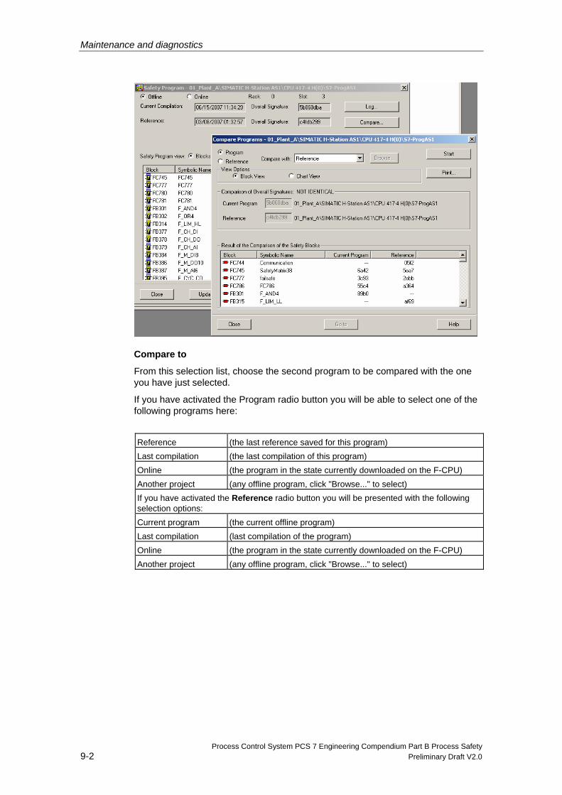
Maintenance and diagnostics
Process Control System PCS 7 Engineering Compendium Part B Process Safety 9-2 Preliminary Draft V2.0
Compare to
From this selection list, choose the second program to be compared with the one you have just selected.
If you have activated the Program radio button you will be able to select one of the following programs here:
Reference (the last reference saved for this program) Last compilation (the last compilation of this program) Online (the program in the state currently downloaded on the F-CPU) Another project (any offline program, click "Browse..." to select) If you have activated the Reference radio button you will be presented with the following selection options: Current program (the current offline program) Last compilation (last compilation of the program) Online (the program in the state currently downloaded on the F-CPU) Another project (any offline program, click "Browse..." to select)

![MANUAL - Garmin · General settings and Training settings General settings In the menu left click on [Settings]. The General settings are for the general display. Language The standard](https://img.pdfslide.us/doc/110x75/5f9ad8bee7f94767a440344e/manual-garmin-general-settings-and-training-settings-general-settings-in-the-menu.jpg)


![C:Documents and Settings ic-GEP220-1(4PP)ES(0712)[1]](https://img.pdfslide.us/doc/110x75/62decd86d9b434298877f4c2/cdocuments-and-settings-ic-gep220-14ppes07121.jpg)
