Embed Size (px)
Citation preview

Page 1 of 8
2015-01-XXXX
Predictive simulations of damage propagation in laminated composite materials and
structures with SAMCEF
Bruyneel M.1, Naito T.
2, Urushiyama Y.
2, MacDougall S.
3
1SAMTECH s.a. (A Siemens Company) Belgium,
2Honda R&D Japan,
3Siemens PLM US
Copyright © 2015 SAE International
Abstract
In this paper, the advanced damage analysis of composite materials
and structures made of continuous fibers embedded in a polymer
matrix is addressed. The solution is based on the SAMCEF finite
element code, which is now available in the SIEMENS NX CAE
environment, with the specific focus of solving non-linear analysis
problems for composites. Globally speaking, SAMCEF is an implicit
non-linear solver able to solve quasi-static and dynamic problems,
with a comprehensive library of structural elements and kinematic
joints.
First, the sizing strategy based on the building block approach
(pyramid of physical and virtual tests) is recalled. Applied for years
in the aerospace industry, it is here extended to the automotive
context. In this approach, the knowledge on the composite material
and structure is built step by step from the coupon level up to the
final full scale structure. In this paper, stages of the pyramid starting
from the coupon level are considered, and the predictions obtained by
numerical simulations are validated by test results.
The non-linear analysis approach available in the SAMCEF finite
element code is then described. It is based on the continuum damage
mechanics, and is used to study the progressive failure of composites
in the plies and at their interface (delamination). The material models
are described. The identification procedure for these damage models
is also discussed: it is based on a very limited number of tests results
at the coupon level. It is then shown how this information on the
material behavior can be used at upper stages of the building block
approach and so applied to larger scale structures and/or more
complex load cases and different stacking sequences.
The very good agreement obtained in this paper between simulation
and test results on composite structures of increasing complexity tend
to demonstrate that SAMCEF can be used as a predictive numerical
tool for the evaluation of the non-linear behavior of composites,
including the progressive inter- and intra-laminar damage analysis.
Introduction
Composite materials have been used successfully in the aerospace
industry for many years due to their light weight and high mechanical
performances. At the opposite, the amount of carbon fiber reinforced
plastics (CFRP) used in the automotive industry is still limited to
very specific applications and still not really appears as a reliable
solution as far as structural heavily loaded components are
concerned. However, vehicle manufacturers and tier suppliers are
facing the challenge of consistently maintaining high quality end-
product with safety constraints while designing lightweight structures
with fuel economy concerns. Carbon fiber-reinforced plastics,
because of their high strength to density ratio, represent a serious
alternative to classical metallic approach but generate the need to
completely redefine the design and sizing methodology of the
structural parts. Indeed, composites exhibit complex material
behaviors, especially when the assumption of linearity cannot be
done anymore. Moreover, composite materials and structures have
complex failure modes, which must be well controlled in the sizing
process. In this context, predictive simulation tools can be a helpful
companion to the physical tests.
In order to propose predictive simulation tools, it is important to use
material models able to represent the different modes of degradation
of the plies forming the laminated composite structure. Although
delamination is a very important mode of failure, intra-laminar failure
modes can’t be ignored. Inter- and intra-laminar damage modes are
studied in this paper, and progressive damages impacting
delamination, matrix cracking, fibers breaking, and de-cohesion
between fibers and matrix are considered.
Even if lots of models are available in the literature [1-6], the
formulation developed in SAMCEF for modeling the damages inside
the unidirectional plies of a laminate is based on the continuum
damage mechanics approach initially developed in [7], in which the
laminate is made of homogenous plies (of various orientations) and
damage variables impacting the stiffness of each ply are associated to
the different failure modes representing the fiber breaking, matrix
cracking and de-cohesion between fibers and matrix. The advantage
of this progressive damage model compared to some others is that a
parameter identification procedure can be developed. This procedure
is based on test results at the coupon level, and allows determining
not only the elastic properties but also the value of the parameters
describing the non-linear behavior of the material. In this paper, the
damage model is first presented, and then the parameter identification
procedure is discussed. The parameter values are validated based on a
comparison between test and simulation results on a coupon with a
stacking sequence that was not used for the identification.
Although different modeling and analysis approaches exist in the
literature and in commercial software for modeling delamination [8-
13], the cohesive element formulation and relevant associated
damage models are here considered [14]. The approach is based on
continuum damage mechanics and was initially developed in [15].
The damage model is assigned to some interface elements inserted
between the plies to represent their possible de-cohesion and a

Page 2 of 8
fracture criterion is used to decide on the inter-laminar crack
propagation. Using such cohesive elements in the analysis allows
estimating not only the propagation load but also to predict the failure
load, the crack propagation path and the residual stiffness during the
fracture process in an automatic way. With this information more
accurate safety margins can be assessed. The basics of the parameter
identification procedure of such a material model will be briefly
explained: test results at the coupon level on DCB and ENF
specimens are used to identify the parameters of the damage law.
Once validated at the coupon level, the damage models (for inter and
intra-laminar damages) can be used at the upper stages of the
pyramid in order to determine the non-linear behavior of larger
components and/or more complex load cases and different stacking
sequences, where now predictive simulations are the companions of
physical tests. Even if the dynamic effects can be treated by the
proposed numerical solution, quasi-static tests only are considered in
this paper. The material models presented here for inter- and intra-
laminar failures are comprehensively implemented in SAMCEF and
there is no need for additional plug-ins to solve the progressive
damage problem.
The sizing of composite structures
The structures and materials considered in this paper are thin-walled
structures made of plies with continuous unidirectional fibers
embedded in a polymer matrix. Such composite materials are
extensively used in the primary structures of aircrafts. The design of
structural composites for advanced applications is nowadays
conducted with computers and numerical tools. As explained in [16],
it classically involves two disciplines. The first one, called Computer
Aided Design (CAD), aims at defining the overall geometry of the
part, and the regions of laminates with their stacking sequence. It is
linked to the Computer Aided Manufacturing (CAM) and provides
specific capabilities for the manufacturing processes simulation. Such
capabilities are used to determine the accurate fibers orientations and
the deformation of the plies during the draping. At that stage,
software like Fibersim can be used. The second discipline, called
Computer Aided Engineering (CAE), is used to analyze the structural
integrity of the composite structure when it is subjected to the
expected loads. In this paper, we only address CAE. It is well know
from the aerospace industry that composite structures are sized based
on the building block approach [17]. This methodology is described
in Figure 1, with the pyramid concept. The idea is to build the
knowledge on the material and structural behaviors step by step,
starting from the fundamental stage at the coupon level up to the full
scale (i.e. the full wing or even the full aircraft). It has been observed
over the years that simulation, and especially models based on the
finite element method, are more and more used on the different stages
of the pyramid, trying to become a companion of the physical tests. It
is indeed evident that tests can be expensive when repeated several
times for different material configurations (e.g. different stacking
sequences) or when changes in the components geometry or loading
are studied, and so using virtual testing can help reduce the product
development costs. To fulfill this requirement, finite element analyses
must be predictive. If this condition is satisfied, simulation can then
replace some physical tests.
Developing predictive simulation tools is clearly a challenge. The
simulation tools should be able to address different attributes,
covering static or quasi-static analyses, damage analyses, fatigue,
dynamic response, crash, NVH, etc.
Figure 1. The building block approach applied to aerospace composite
structures.
The introduction of effective composite structures in primary parts of
automotive vehicles should rely on the approach described in Figure
2, in which the first stages of the pyramids are identical to the ones of
Figure 1, and specific applications only appear at the upper stages of
the sizing process. The analyst of the automotive industry is therefore
confronted to the same problems as the analyst in the aerospace
sector: he also needs predictive simulation tools, for the attributes
mentioned previously [18].
Figure 2. The building block approach applied to automotive composite
structures.
Need for a damage tolerant approach
When a laminated composite structure is submitted to a low energy
impact, damage may appear inside the structure, especially between
the plies. The main issue is that, depending on the energy of the
impact, this damage is sometimes not visible (Figure 3). Such
damages can actually also appear during the handling of the
composite part, or as a result of the manufacturing process. This
implies that, in order to avoid overdesigns and not neglect the real
behavior of composite materials, composite structures must be sized
with a damage tolerant approach, allowing the presence of damage or
assuming that damage may be present in the structure even when not
visible, in order to determine safe and tight material allowable for the
upper stages of the pyramid.
There are of course several ways to address damage with numerical
methods. In this paper, the formulation doesn’t rely on a multi-scale
approach but is based on the continuum damage mechanics and
meso-models of the homogenized plies and of the interface are used,
which represent the lowest scale in the modelling (Figure 4).
However, the physics represented by these meso-models come from a
detailed observation of micro, meso and macroscopic behaviors of
Page 3 of 8
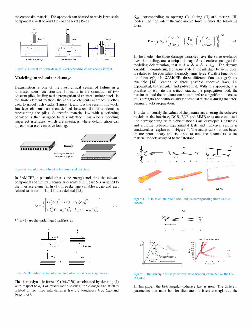
the composite material. The approach can be used to study large scale
components, well beyond the coupon level [19-21].
Figure 3. Illustration of the damage level depending on the energy impact.
Modeling inter-laminar damage
Delamination is one of the most critical causes of failure in a
laminated composite structure. It results in the separation of two
adjacent plies, leading to the propagation of an inter-laminar crack. In
the finite element method, the cohesive elements approach is often
used to model such cracks (Figure 4), and it is the case in this work.
Interface elements are then defined between the finite elements
representing the plies. A specific material law with a softening
behavior is then assigned to this interface. This allows modeling
imperfect interfaces, which are interfaces where delamination can
appear in case of excessive loading.
Figure 4. An interface defined in the laminated structure.
In SAMCEF, a potential (that is the energy) including the relevant
components of the strain tensor as described in Figure 5 is assigned to
the interface elements. In (1), three damage variables dI, dII and dIII ,
related to modes I, II and III, are defined [15]:
−+−+
−+= +−
232
0231
0
233
0233
0
)1()1(
)1(
2
1
γγ
εε
IIIIIIIIII
IIId
dkdk
dkke (1)
ki0 in (1) are the undamaged stiffnesses.
Figure 5. Definition of the interface and inter-laminar cracking modes.
The thermodynamic forces Yi (i=I,II,III) are obtained by deriving (1)
with respect to di. For mixed mode loading, the damage evolution is
related to the three inter-laminar fracture toughness GIC, GIIC and
GIIIC corresponding to opening (I), sliding (II) and tearing (III)
modes. The equivalent thermodynamic force Y takes the following
form:
αααα
τ
/1
sup
+
+
=
≤ IIIC
III
IIC
II
IC
IIC
t G
Y
G
Y
G
YGY (2)
In the model, the three damage variables have the same evolution
over the loading, and a unique damage d is therefore managed for
modeling delamination, that is d = dI = dII = dIII . The damage
variable d, considering the failure state at the interface between plies,
is related to the equivalent thermodynamic force Y with a function of
the form g(Y). In SAMCEF, three different functions g(Y) are
available [14], leading to three possible cohesive laws, i.e.
exponential, bi-triangular and polynomial. With this approach, it is
possible to estimate the critical cracks, the propagation load, the
maximum load the structure can sustain before a significant decrease
of its strength and stiffness, and the residual stiffness during the inter-
laminar cracks propagation.
In order to identify the values of the parameters entering the cohesive
models in the interface, DCB, ENF and MMB tests are conducted.
The corresponding finite element models are developed (Figure 6),
and a fitting between experimental tests and numerical results is
conducted, as explained in Figure 7. The analytical solutions based
on the beam theory are also used to tune the parameters of the
material models assigned to the interface.
Figure 6. DCB, ENF and MMB tests and the corresponding finite element
models
Figure 7. The principle of the parameter identification, explained on the ENF
test case.
In this paper, the bi-triangular cohesive law is used. The different
parameters that must be identified are the fracture toughness, the

Page 4 of 8
initial stiffnesses and the interface strengths. Figures 8 to 10 represent
the numerical responses when the interface parameters have been
determined with the fitting process. Here, the coupling parameter of
(2) is equal to 1, and the MMB test is used to validate the parameters
values determined based on DCB and ENF.
Figure 8. Results for DCB and ENF, for a [0]16 stacking sequence [22,24]
Figure 9. Results for DCB and ENF, for a stacking sequence including 45°
and -45°layers [22,24]
It is observed in Figure 8 that for a [0]n laminate the behavior of the
ENF test is quasi-linear up to the crack propagation load, which is the
maximum point of the reaction-displacement curve. However, when
the laminate includes ±45° orientations, the non-linear behavior
observed in the tests can only be reproduced when the damage inside
the plies is modeled. Doing so, we note a very good agreement
between tests (light lines) and simulation (dark spots). For DCB,
intra-laminar damage is not observed. The next section describes the
strategy for the progressive damage modeling inside the plies.
Figure 10. Validation on the MMB [22,24]
Modeling intra-laminar damage
Although delamination is certainly the most frequent mode of failure
in laminated composites, in practical applications it is necessary to
consider the ply degradation as well, as just demonstrated from
Figure 9. Besides the classical failure criteria such as Tsai-Hill, Tsai-
Wu and Hashin, an advanced degradation model is available in
SAMCEF. This ply damage model relies on the development
proposed in Ladeveze and LeDantec [7]. For intra-laminar damage,
the following potential with damage, named ed, is used (3), where d11,
d22 and d12 are the damages related to the fibers, the transverse and
the shear directions, respectively (Figure 11).
01212
212
02
222
0222
222
221101
012
0111
211
)1(2
2)1(2)1(2
Gd
EEdEEded
−+
+−
−−−
= −+
σ
σσσσ
νσ
(3)
The thermodynamic forces are derived from this potential and
manage the evolution of the damages, via relations such as d11 = g11
(Y11), d22 = g22 (Y12,Y22) and d12 = g12 (Y12,Y22). A delay effect can
also be defined in order to smooth the occurrence of the damages.
Moreover, non-linearities are introduced in the fiber direction, in
tension and compression. For instance, the thermodynamic force
associated to shear is given by:
012
212
212
1212
)1(2 Gdd
eY d
−=
∂
∂−=
σ
In Figure 12, it is seen that for a laminate submitted to pure shear
(σ12,γ12), a decrease in the stiffness is observed after some
loading/unloading scenarios of increased amplitude, reflecting that
damage occurs in the matrix. Moreover, unloading reveals the
existence of permanent deformation, which is taken into account via
a plasticity model. On top of that, non-linearities are introduced in the
fiber direction, in tension and compression (Figure 13). It is noted
from equation (3) that in the transverse direction, only tension leads
to damage, but not compression, assuming the unilateral action of
damage in direction 2 (crack closure in the matrix in compression).
These behaviors result from the tests interpretation [7].
Figure 11. Possible damages in a UD ply, impacting fiber failure, matrix
cracking and de-cohesion between fibers and matrix; model of the coupon.
From the coupon testing conducted on standard machines according
to some standards like ASTM and equipped with strain gauges, the
longitudinal stress σL and the axial and transversal strains (εL and εT)
are obtained. Based on this information, the material behavior in each
ply can be determined. Four series of tests are conducted, each one on
a specific stacking sequence and/or loading scenario. As 5 successful
tests are usually required, it means that 20 successful tests must be
conducted to cover the 4 series. This is enough to identify the
parameters of the progressive damage ply model as well as the elastic
properties. The identification procedure is done without extensive use
of simulation. It is rather a procedure based on EXCEL sheets, which
can be speed up by using some very simple FORTRAN
programming. A comparison between tests and simulation is used to
validate the identified values.

Page 5 of 8
Figure 12. Non-linear behaviors captured by the SAMCEF intra-laminar
damage model; matrix behavior
Figure 13. Non-linear behaviors captured by the SAMCEF intra-laminar
damage model; fiber direction
The required stacking sequences mentioned above are not arbitrary;
they are instead well defined, in order to be able to identify the whole
set of elastic properties, the evolution of the damage and of the non-
linearities of the material. One of these specific stacking sequences is
made of plies at ±45°. The loading scenario is either classical,
meaning that the coupon is loaded up to the final failure, or it is based
on the loading/unloading (cyclic) sequences as described in Figure
12. As an example, a [±45]2s laminate is studied. Based on the tests
results as given in Figure 14, the evolution of the damage variable d12
is plotted as a function of the equivalent thermodynamic force Y12.
The hardening law of the plastic model is also identified. This allows
determining the curves of Figure 12, which then feed the material
model of SAMCEF. In Figure 15, it is checked that the results
obtained with SAMCEF are in a very good agreement with the test
results, not only for the global non-linear behavior, but also for the
failure load estimation, the damage evolution (stiffness decrease
measured during unloading) and the permanent deformation
(plasticity). It is clear from Figure 15 that plasticity can’t be
neglected when studying polymer matrix composites. The non-
linearities (hysteresis) appearing during loading/unloading, which is
certainly due to friction between fibers and matrix, are not taken into
account in the model. Our experience is that it doesn’t influence the
results. A specific angle ply laminate is considered to identify the
material behavior in the transverse direction, which is actually
coupled to shear. In order to take into account the coupling between
shear and transverse effects, an equivalent thermodynamic force Y is
used (4), and the evolution of d22 is, moreover, proportional to d12:
2212 bYYY += and 1222 cdd = (4)
Figure 14. Identification of the damage evolution in shear and of the
hardening for the plastic behavior [23,24].
The material behavior in the pure transverse direction is also
identified, as illustrated in Figure 16 (left). The resulting damage
laws evolutions are also given in Figure 16 (right). This information
feeds the progressive damage ply model of SAMCEF.
Figure 15. Comparison between tests and simulation results for a laminate
made up of ±45° plies [23,24]
Figure 16. Transverse behavior and full intra-laminar damage evolution
[23,24].
In Figure 17, the evolution of the stiffness modulus E11 in the fiber
direction is identified, in tension (hardening effect) and compression
(softening effect). The softening effect appearing in compression is
(partly) due to fiber micro-buckling. The (very small) hardening
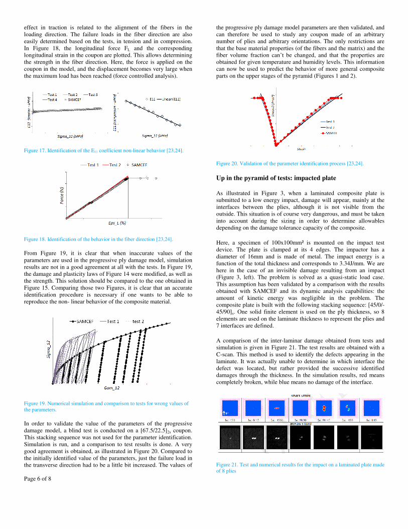
Page 6 of 8
effect in traction is related to the alignment of the fibers in the
loading direction. The failure loads in the fiber direction are also
easily determined based on the tests, in tension and in compression.
In Figure 18, the longitudinal force FL and the corresponding
longitudinal strain in the coupon are plotted. This allows determining
the strength in the fiber direction. Here, the force is applied on the
coupon in the model, and the displacement becomes very large when
the maximum load has been reached (force controlled analysis).
Figure 17. Identification of the E11 coefficient non-linear behavior [23,24].
Figure 18. Identification of the behavior in the fiber direction [23,24].
From Figure 19, it is clear that when inaccurate values of the
parameters are used in the progressive ply damage model, simulation
results are not in a good agreement at all with the tests. In Figure 19,
the damage and plasticity laws of Figure 14 were modified, as well as
the strength. This solution should be compared to the one obtained in
Figure 15. Comparing those two Figures, it is clear that an accurate
identification procedure is necessary if one wants to be able to
reproduce the non- linear behavior of the composite material.
Figure 19. Numerical simulation and comparison to tests for wrong values of
the parameters.
In order to validate the value of the parameters of the progressive
damage model, a blind test is conducted on a [67.5/22.5]2s coupon.
This stacking sequence was not used for the parameter identification.
Simulation is run, and a comparison to test results is done. A very
good agreement is obtained, as illustrated in Figure 20. Compared to
the initially identified value of the parameters, just the failure load in
the transverse direction had to be a little bit increased. The values of
the progressive ply damage model parameters are then validated, and
can therefore be used to study any coupon made of an arbitrary
number of plies and arbitrary orientations. The only restrictions are
that the base material properties (of the fibers and the matrix) and the
fiber volume fraction can’t be changed, and that the properties are
obtained for given temperature and humidity levels. This information
can now be used to predict the behavior of more general composite
parts on the upper stages of the pyramid (Figures 1 and 2).
Figure 20. Validation of the parameter identification process [23,24].
Up in the pyramid of tests: impacted plate
As illustrated in Figure 3, when a laminated composite plate is
submitted to a low energy impact, damage will appear, mainly at the
interfaces between the plies, although it is not visible from the
outside. This situation is of course very dangerous, and must be taken
into account during the sizing in order to determine allowables
depending on the damage tolerance capacity of the composite.
Here, a specimen of 100x100mm² is mounted on the impact test
device. The plate is clamped at its 4 edges. The impactor has a
diameter of 16mm and is made of metal. The impact energy is a
function of the total thickness and corresponds to 3.34J/mm. We are
here in the case of an invisible damage resulting from an impact
(Figure 3, left). The problem is solved as a quasi-static load case.
This assumption has been validated by a comparison with the results
obtained with SAMCEF and its dynamic analysis capabilities: the
amount of kinetic energy was negligible in the problem. The
composite plate is built with the following stacking sequence: [45/0/-
45/90]s. One solid finite element is used on the ply thickness, so 8
elements are used on the laminate thickness to represent the plies and
7 interfaces are defined.
A comparison of the inter-laminar damage obtained from tests and
simulation is given in Figure 21. The test results are obtained with a
C-scan. This method is used to identify the defects appearing in the
laminate. It was actually unable to determine in which interface the
defect was located, but rather provided the successive identified
damages through the thickness. In the simulation results, red means
completely broken, while blue means no damage of the interface.
Figure 21. Test and numerical results for the impact on a laminated plate made
of 8 plies

Page 7 of 8
In Figure 22, a correspondence is done between the defects
determined with the C-scan and the numerical results obtained with
SAMCEF. A very good agreement is observed.
Figure 22. Test and numerical results for the impact on a laminated plate made
of 8 plies; correspondence between C-scan and simulation.
A [45/0/-45/90]3s laminate was also studied, as illustrated in Figure
23. Even if some similarities are clearly observed, it is anyway more
complicated to make a direct link between test and simulation results
because of the large number of interfaces. Only 9 pictures are taken
on each side of the laminate (named “front” for the top face and
“back” for the bottom face).
Figure 23. Test and numerical results for the impact on a laminated plate made
of 24 plies.
Based on these good results, SAMCEF was then used as a predictive
simulation tool to estimate the damage appearing in laminates made
of different stacking sequences, for which no physical tests were
conducted.
Up in the pyramid of tests: L-shaped beam
The L-shaped beam is submitted to an imposed vertical displacement
on its upper face and is clamped on its vertical leg, as illustrated in
Figures 24 and 25. The laminated L-shaped beam is made of 12 plies,
with the following stacking sequence [60/-60/0/0/-60/60]s. The
developed model is illustrated in Figure 25. Contact elements are
used and rigid bodies transmit the loading to the composite part. One
solid finite element is used on the ply thickness, so 12 elements are
used on the laminate thickness to represent the plies and 11 interfaces
are defined.
Figure 24. The L-shaped beam and the boundary conditions.
Figure 25. The model of the L-shaped beam.
Deformed configurations are illustrated in Figure 26. The global
deformations obtained with the numerical method are in good
agreement with the pictures taken during the physical test. Anyway,
as for the available pictures the loading amplitude associated to the
test results is not known, only a quantitative comparison can be
made. From simulation, it is observed that even if damage appears
inside the plies delamination is predominant in this case. The load-
displacement curve is given in Figure 27, where a comparison is done
between test and simulation results.
Figure 26. The L-shaped beam in two loading configurations
Conclusions
In this paper, the non-linear behavior of laminated composite
materials and structures made of UD plies was studied. Physical tests
and numerical analyses were conducted. The specific damage models
available in the SAMCEF finite element code were used for modeling
the inter- and intra-laminar damages.
First, tests results at the coupon level are used to identify the value of
the parameters of the damage models. These values are validated at
the coupon level. Then, the material models are used to study more
complicated composite structures and/or loading at upper stages of

Page 8 of 8
the pyramid of tests. The cases of an impacted plate and of a L-
shaped beam submitted to bending are studied. The very good
agreement obtained between simulations and tests tend to
demonstrate that SAMCEF can be used as a predictive numerical tool
for the evaluation of the non-linear behavior of composites including
damage.
Figure 27. The L-shaped beam load-displacement curve: tests and simulation.
References
1. Katerelos, D.D.G., Kashtalyan, M., Soutis, C., Galiotis, C.
"Matrix cracking in polymeric composites laminates: modeling
and experiments". Composite Science & technology, 68: 2310-
2317, 2008.
2. Tan, S.C. and Nuismer R.J. "A theory for progressive matrix
cracking in composite laminates", J. Compos. Mater., 23: 1029–
47, 1989.
3. Li S., Reid S.R. and Soden P.D. "A continuum damage model
for transverse matrix cracking in laminated fibre-reinforced
composites", Philos Trans R Soc Lond Ser A (Math Phys Eng
Sci), 356: 2379–412, 1998.
4. Adolfsson, E. and Gudmundson, P. "Matrix crack initiation and
progression in composite laminates subjected to bending and
extension", Int. J. Solids Struct., 36: 3131–69, 1999.
5. Katerelos, D.T.G, Varna, J. and Galiotis, C. "Energy criterion
for modeling damage evolution in cross-ply composite
laminates", Compos Sci Technol, 68: 2318–24, 2008.
6. Mayugo, J.A., Camanho, P.P., Maimi, P. and Dávila, C.G.
"Analytical modeling of transverse matrix cracking of [±h/90n]
composite laminates under multiaxial loading", Mech Adv Mater
Struct, 17: 237–45, 2010.
7. Ladeveze, P. and Le Dantec, S. "Damage modeling of the
elementary ply for laminated composites", Composites Science
& Technology, 43: 123-134, 1992.
8. Krüeger, R. 2007. "An approach for assessing delamination
propagation capabilities in commercial finite element codes",
American Society of Composites 22nd Annual Technical
Conference, University of Washington, Seattle, WA, September
17-19, 2007.
9. Camanho, P.P. 2006. "Finite element modeling of fracture in
composites: current status and future developments", NAFEMS
Seminar – Prediction and Modeling of Failure Using FEA.
NAFEMS, Roskilde, Denmark, 2006.
10. Krüeger, R. "Virtual Crack Closure technique: history, approach
and applications". Applied Mechanics Reviews 57: 109-143,
2004.
11. Krüeger, R. "Three dimensional finite element analysis of
multidirectional composite DCB, SLB and ENF specimens",
ISD-Report N° 94/2, Institute for Statics and Dynamics of
Aerospace Structures, University of Stuttgart, 1994.
12. Orifici, A.C., Thomson, R.S., Degenhardt, R., Bisagni, C., and
Bayandor, J. "Development of a finite element analysis
methodology for the propagation of delaminations in composite
structures". Mechanics of Composite Materials, 43: 9-28, 2007.
13. Xie, D. and Bigger, S.B. "Progressive crack growth analysis
using interface element based on the Virtual Crack Closure
Technique". Finite Elements in Analysis and Design 42: 977-
984, 2006.
14. Bruyneel, M., Delsemme, J.P., Jetteur, P. and Germain, F.
"Modeling inter-laminar failure in composite structures:
illustration on an industrial case study", Applied Composite
Materials, 16: 149-162, 2009.
15. Allix, O. and Ladevèze, P. "Interlaminar interface modelling for
the prediction of laminate delamination", Composite Structures,
22: 235-242, 1992.
16. Bruyneel M. and Diaconu C. "Structural composite design:
concepts and considerations", Encyclopedia of Composites,
Wiley & Sons, 2012.
17. Baker A., Dutton S., and Kelly D. "Composite Materials for
Aircraft Structures", AIAA Education Series, Reston, 2004.
18. Farkas L., Liefooghe C., Bruyneel M., Hack M., Van Genechten
B., Donders S., and Van der Auweraer H. "Roadmap for
addressing the automotive engineering challenges in composite
development", Tools and Methods of Competitive Engineering
(TMCE2014), Budapest, Hungary, May, 2014.
19. Bruyneel M., Delsemme J.P., Jetteur P., Germain F. and
Boudjemaa N. (2014). "Damage modelling of composites:
validation of inter-laminar damage model at the element level",
JEC Composites Magazine, 90, June 2014.
20. Bruyneel M., Degenhardt R. and Delsemme J.P. "An industrial
solution to simulate post-buckling and damage of composite
panels", JEC Composites Magazine, 48, May 2009.
21. Galucio A.C., Jetteur P., Trallero D., Charles J.P. "Toward
numerical fatigue prediction of composite structures :
application to helicopter rotor blades", 3rd ECCOMAS
Conference on the Mechanical Response of Composites, 21-23,
Hannover, Germany, 2011.
22. Bruyneel M., Delsemme J.P., Goupil A.C., Jetteur P., Lequesne
C., Naito T., Urushiyama Y. "Damage modeling of laminated
composites : validation of the inter-laminar damage law of
SAMCEF at the coupon level for UD plies", World Congress of
Computational Mechanics, WCCM11, Barcelona, Spain, 20-25
July, 2014.
23. Bruyneel M., Bruyneel M., Delsemme J.P., Goupil A.C., Jetteur
P., Lequesne C., Naito T., Urushiyama Y. "Damage modeling of
laminated composites : validation of the intra-laminar damage
law of SAMCEF at the coupon level for UD plies", European
Conference on Composite Material, ECCM16, Sevilla, Spain,
22-26 June, 2014.
24. Bruyneel M., Delsemme J ;P., Goupil A.C., Jetteur P., Lequesne
C., Naito T., Urushiyama Y. "Validation of material models for
inter and intra-laminar damage in laminated composites", 2014
ASC 29/US-Japan 16 ASTM D30 Conference, UC, San Diego,
USA, September 2014.
Contact Information
In case of question or need for additional information on this work,
please contact Dr. Yuta Urushiyama (Honda R&D, Tochigi, Japan:
[email protected]) and Prof. Dr. Michael
Bruyneel (SAMTECH, A Siemens Company, Liège, Belgium: