Embed Size (px)
Citation preview
RTO-MP-AVT-170 PAPER NBR - 1
NATO UNCLASSIFIED + SWE
NATO UNCLASSIFIED + SWE
Prediction of Manoeuvring Properties for a Tanker Model by Computational Fluid Dynamics
Riccardo Broglia Giulio Dubbioso
Andrea Di Mascio CNR-INSEAN, Via del Vallerano 139, 00143, Rome, Italy
[email protected], [email protected], [email protected]
ABSTRACT
The turning circle manoeuvre of a self-propelled tanker like ship model is numerically simulated through the integration of the unsteady Reynolds Averaged Navier-Stokes (URANS) equations coupled with the equations of the motion of a rigid body. The solution is achieved by means of the unsteady RANS solver developed at CNR-INSEAN. The model is considered with two different stern appendages configurations (each one providing a different dynamic behaviour): twin screw with a single rudder and twin screw, twin rudder with a central skeg. Each propeller is taken into account by a model based on the actuator disk concept; anyhow, in order to correctly capture the turning manoeuvring behaviour of the model, a suitable description of the propeller performance in oblique flow operation has be considered. Comparison with experimental data from free running tests will demonstrate the feasibility of the CFD computations. The main features of the flow field, with particular attention to the vortical structures detached from the hull is presented as well.
1.0 INTRODUCTION
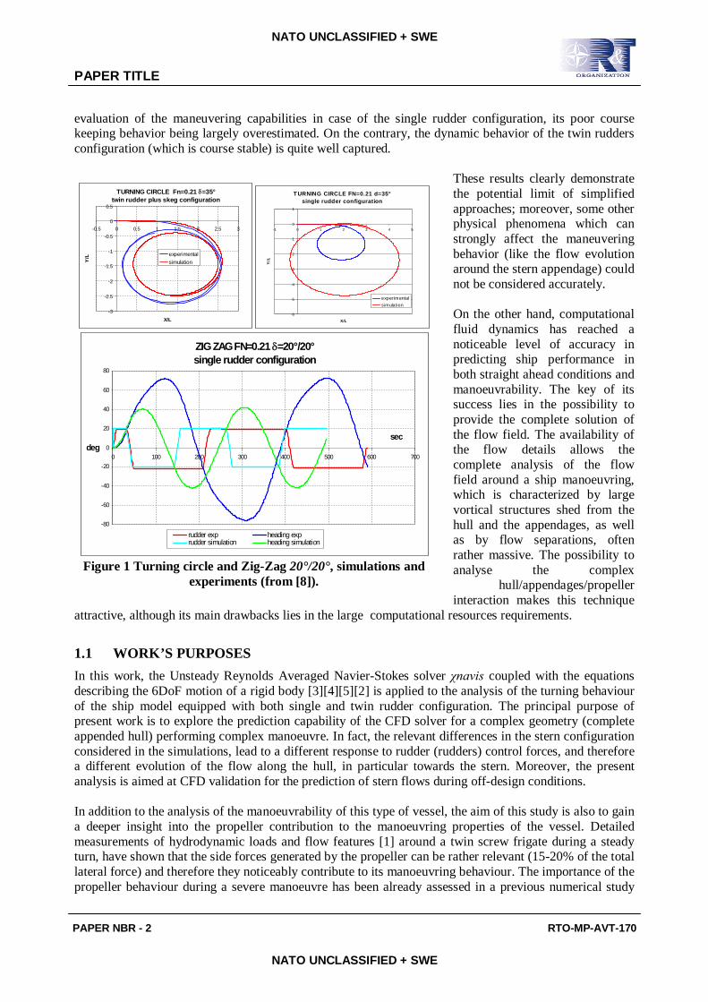
The prediction of the dynamic stability and maneuverability behavior of a ship are among the most challenging problems in naval hydrodynamics; the main difficulties arise in the accurate evaluation of the hydrodynamic forces and moments which characterize the dynamic response of the vessels and its motion. Traditional approaches, like system based maneuvering model or potential based methods are extensively utilized, the negligible computational resource requirements being the key of their success. These approaches are widely used during the preliminary design phase. However, despite they guarantee a satisfactory compromise among resource demand and reliability of results, they cannot provide detailed information about the flow field around the hull and necessitate continuous verification and validation in case of novel hull forms [16][17]. Extensive studies performed on a series of twin screw vessels (including the two tanker-like models considered in present study and other 5 twin rudder configurations) [18][6][8] emphasized the potential limit of lumped models (regression based). In particular, it has been evidenced that the stern appendages region is a key aspect of the maneuverability of this kind of ships, and, if not properly represented in the mathematical model, rather misleading results can be obtained. This issue was remarkable in case of the tanker-like vessel, for both the twin rudder plus central skeg configuration and the single rudder one: it has been observed that all the regression models provided poor prediction of the maneuvering capabilities when applied to the single rudder configuration, in spite of satisfactory predictions for the twin rudder configuration. In Figure 1 simulation results from [8] are compared with experiments for two maneuvers, i.e. a severe turning circle at FN =0.21 (for the two configurations) and a 20°/20° Zig-Zag maneuver (only for the single rudder configuration). It can be observed that semi-empirical regressions completely fail in the
brought to you by COREView metadata, citation and similar papers at core.ac.uk
provided by PUblication MAnagement
PAPER TITLE
PAPER NBR - 2 RTO-MP-AVT-170
NATO UNCLASSIFIED + SWE
NATO UNCLASSIFIED + SWE
evaluation of the maneuvering capabilities in case of the single rudder configuration, its poor course keeping behavior being largely overestimated. On the contrary, the dynamic behavior of the twin rudders configuration (which is course stable) is quite well captured.
These results clearly demonstrate the potential limit of simplified approaches; moreover, some other physical phenomena which can strongly affect the maneuvering behavior (like the flow evolution around the stern appendage) could not be considered accurately. On the other hand, computational fluid dynamics has reached a noticeable level of accuracy in predicting ship performance in both straight ahead conditions and manoeuvrability. The key of its success lies in the possibility to provide the complete solution of the flow field. The availability of the flow details allows the complete analysis of the flow field around a ship manoeuvring, which is characterized by large vortical structures shed from the hull and the appendages, as well as by flow separations, often rather massive. The possibility to analyse the complex
hull/appendages/propeller interaction makes this technique
attractive, although its main drawbacks lies in the large computational resources requirements.
1.1 WORK’S PURPOSES In this work, the Unsteady Reynolds Averaged Navier-Stokes solver χnavis coupled with the equations describing the 6DoF motion of a rigid body [3][4][5][2] is applied to the analysis of the turning behaviour of the ship model equipped with both single and twin rudder configuration. The principal purpose of present work is to explore the prediction capability of the CFD solver for a complex geometry (complete appended hull) performing complex manoeuvre. In fact, the relevant differences in the stern configuration considered in the simulations, lead to a different response to rudder (rudders) control forces, and therefore a different evolution of the flow along the hull, in particular towards the stern. Moreover, the present analysis is aimed at CFD validation for the prediction of stern flows during off-design conditions. In addition to the analysis of the manoeuvrability of this type of vessel, the aim of this study is also to gain a deeper insight into the propeller contribution to the manoeuvring properties of the vessel. Detailed measurements of hydrodynamic loads and flow features [1] around a twin screw frigate during a steady turn, have shown that the side forces generated by the propeller can be rather relevant (15-20% of the total lateral force) and therefore they noticeably contribute to its manoeuvring behaviour. The importance of the propeller behaviour during a severe manoeuvre has been already assessed in a previous numerical study
TURNING CIRCLE Fn=0.21 =35°twin rudder plus skeg configuration
-3
-2.5
-2
-1.5
-1
-0.5
0
0.5
-0.5 0 0.5 1 1.5 2 2.5 3
X/L
Y/L experimental
simulation
T URNING CIRCLE FN=0.21 d=35°single rudder configuration
-6
-5
-4
-3
-2
-1
0
1
-1 0 1 2 3 4 5
X/L
Y/L
experimentalsimulation
ZIG ZAG FN=0.21 =20°/20°single rudder configuration
-80
-60
-40
-20
0
20
40
60
80
0 100 200 300 400 500 600 700
secdeg
rudder exp heading exprudder simulation heading simulation
Figure 1 Turning circle and Zig-Zag 20°/20°, simulations and
experiments (from [8]).
PAPER TITLE
RTO-MP-AVT-170 PAPER NBR - 3
NATO UNCLASSIFIED + SWE
NATO UNCLASSIFIED + SWE
[9] on the same vessel under investigation here, in its single rudder configuration. In particular, it has been shown that, if the propeller side force is not taken into account, the turning quality of the ship provided by the numerical simulation is overestimated, i.e. comparing with the free running tests, a tighter turning circle is predicted. In the previous simulations, the propeller effects were taken into account by means of the Hough and Ordway model [11], which, in its original formulation, provides thrust and torque only, whereas transverse forces in the disk plane arising during oblique flow conditions are not accounted for. The addition of a “suitable” propeller lateral force, empirically determined, improved noticeably the results, both in terms of trajectory and kinematic parameters (speed drop, drift angle and yaw rate). In the present work, the generalized actuator disk model has been improved with the inclusion of a lateral force estimation based on the Ribner theory [13]. The proposed model has been used for the investigation of the turning ability of the considered vessel in both configurations; it has to be pointed out that the two configuration have a completely different dynamical behaviour; in particular, the single rudder configuration is directionally unstable, whereas the twin rudder with skeg configuration is slight directionally stable. This makes the test rather challenging for both the numerical algorithm and the proposed propeller model; it will be shown that the classical actuator disk approach must be extended to take oblique flow effects into account. 2.0 NUMERICAL METHODS
The numerical solution of the governing equations is computed by means of the solver χnavis, which is a general purpose simulation code developed at CNR-INSEAN; the code yields the numerical solution of the unsteady Reynolds averaged Navier Stokes equations for unsteady high Reynolds number (turbulent) free surface flows around complex geometries (the interested reader is referred to [3][4][5][7][2] for details). The solver is based on a finite volume formulation with conservative variables co-located at cell centre. The spatial discretization of the convective terms is done with a third order upwind based scheme, whereas the diffusive terms are discretized with second order centred scheme and the time integration is done by second order implicit scheme (three points backward). The solution at each time step is computed iteratively by a pseudo-time integration, that exploits an Euler implicit scheme with approximate factorization, local pseudo time step and multi-grid acceleration [10]. Although several turbulence models have been implemented in the code, in all the simulations reported the turbulent viscosity has been calculated by means of the one-equation model of Spalart and Allmaras [15]. Free surface effects are taken into account by a single phase level-set algorithm [4]. Complex geometries and multiple bodies in relative motion are handled by a dynamical overlapping grid approach [7]. High performance computing is achieved by an efficient shared and distributed memory parallelization [2].
2.1 Propeller Model
In marine CFD simulations the presence of the propeller is often taken into account by a simple model based on the actuator disk concept, according to which body forces are distributed on a disk of finite thickness. Both axial and tangential forces are used in the computation in order to simulate both the acceleration and the increase in swirl that the flow undergoes when passing through the propeller. Such distributions are obtained by blade loads averaging in both time and space. Usually, time averages are taken over one period of revolution, whereas space averages are obtained by distributing blade loads in circumferential direction over the whole propeller disk. Both axial and tangential body forces depend on the actual velocity field; this results in the sum of the nominal wake velocity and the propeller-hull interaction velocity, i.e. the effective wake. The body forces distribution and velocity field are mutually dependent; therefore, in order to take into account for the effective wake, an iterative procedure is required. In this work the propeller is modelled by means of an hybrid model: thrust and torque are evaluated by means of a modified Hough and Ordway model [11], whereas the in plane forces are computed by means of the semi-empirical method proposed by Ribner [12] (which is in turn derived from a blade element approach). In the following subparagraphs, both the modified Hough and Ordway and the

PAPER TITLE
PAPER NBR - 4 RTO-MP-AVT-170
NATO UNCLASSIFIED + SWE
NATO UNCLASSIFIED + SWE
Ribner models will be briefly recalled.
2.1.1 Thrust and Torque (Hough and Ordway Model)
In this model, the propeller loading is computed following the idea proposed by Hough and Ordway [11]: given the advance, thrust and torque coefficients (J, KT, KQ in the following), the axial, radial and tangential force distributions are computed under the assumption of an optimal distribution for the circulation along the blades. The original model was modified to take into account for the axial flow reduction at the propeller disk; in particular, at each time step the advance coefficient is estimated by keeping the number of the revolution constant and by using the instantaneous average axial velocity at the propeller disk inflow section. Then, new values of KT(J) and KQ(J) are estimated from the propeller characteristic curves; the resulting load (longitudinal and tangential) is then distributed over each cell of the propeller disk as volume forces in order to simulate the action of the propeller.
2.1.2 In Plane Loads (Ribner Model) The Ribner’s model [13], very popular in the aeronautic field for the evaluation of airplanes’ stability qualities, was developed on the basis of the main flow characteristics around the propeller in oblique flow, and therefore are strongly related to the loads acting in the propeller plane. When the propeller works with an angle of yaw with respect to the incoming flow, it accelerates the flow behind the disk reducing the angle of attack with respect to the shaft; because the propeller tends to align the flow to its axis. This angle variation results in a lateral momentum provided to the flow by the propeller, and consequently, as a reaction, the propeller experiences a lateral force. This fact is accounted for in Ribner’s theory by means of a hybrid blade element (for the estimation of the loads acting on the propeller blades) and an actuator disk approach (for the evaluation of the effective incidence angle due to propeller induction effect). In the following only the core of the model is presented, and its inclusion in the numerical solver; the interested reader is referred to [13] for the details of its derivation. A propeller moving in the horizontal plane at incidence with respect to the flow (the treatment is analogous in the vertical plane) experiences a lateral force (in the same direction of the in-plane component of velocity) defined by the relation:
VvCCY PROP
YPROPYPROPPROP '''
where YPROPC ' is the hydrodynamic derivative for lateral force for the propeller, is the local angle of attack of the flow with respect to the propeller disk, PROPv is the lateral speed at the propeller andV is the total speed at the propeller disk (velocities in the previous relation are referred to the nominal conditions, i.e. propeller induction is not considered, its effect being included in C’YPROP). The lateral force derivative is expressed by the following relation:
SIDEL
a
SIDEL
SYPROP
ACk
aFACZkC
431
)(43'
where Z is the number of blades, ASIDE is the lateral blade projected area,
LC is the sectional lift
coefficients which has been derived from thin airfoil theory, F(a) is the propeller load factor, defined as:
PAPER TITLE
RTO-MP-AVT-170 PAPER NBR - 5
NATO UNCLASSIFIED + SWE
NATO UNCLASSIFIED + SWE
2
2
)21(1)21()1()1()(
aaaaaF
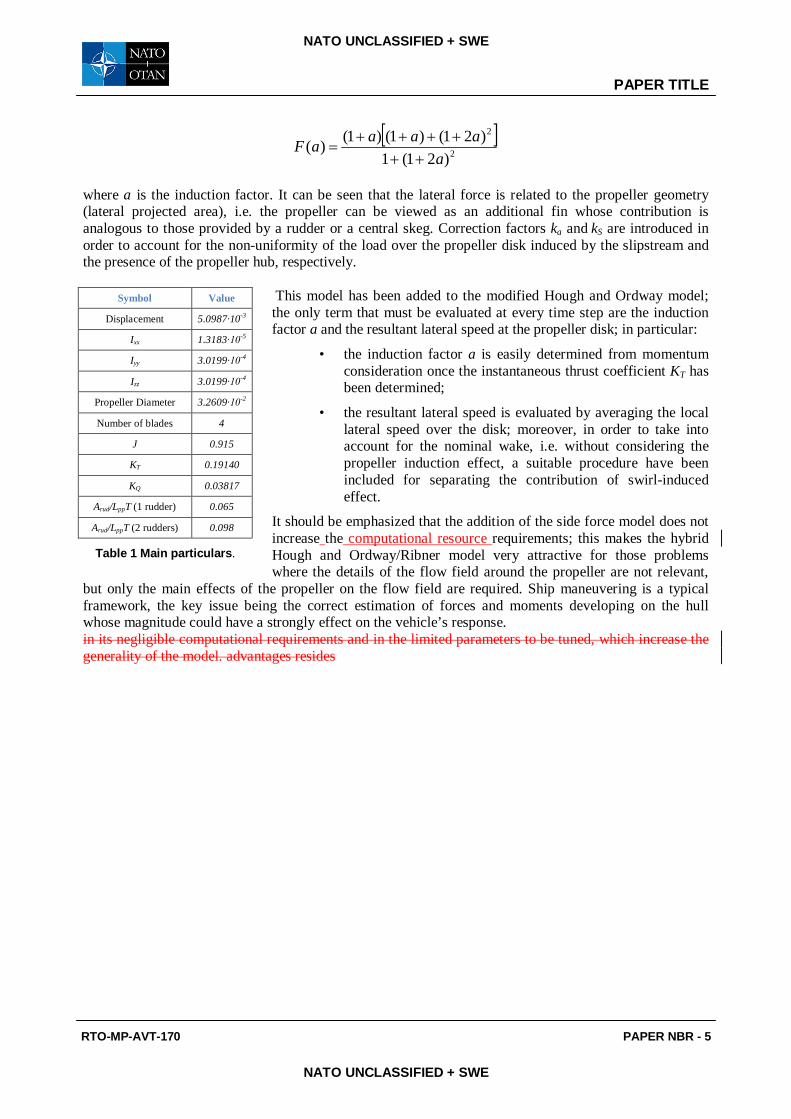
where a is the induction factor. It can be seen that the lateral force is related to the propeller geometry (lateral projected area), i.e. the propeller can be viewed as an additional fin whose contribution is analogous to those provided by a rudder or a central skeg. Correction factors ka and kS are introduced in order to account for the non-uniformity of the load over the propeller disk induced by the slipstream and the presence of the propeller hub, respectively.
This model has been added to the modified Hough and Ordway model; the only term that must be evaluated at every time step are the induction factor a and the resultant lateral speed at the propeller disk; in particular:
• the induction factor a is easily determined from momentum consideration once the instantaneous thrust coefficient KT has been determined;
• the resultant lateral speed is evaluated by averaging the local lateral speed over the disk; moreover, in order to take into account for the nominal wake, i.e. without considering the propeller induction effect, a suitable procedure have been included for separating the contribution of swirl-induced effect.
It should be emphasized that the addition of the side force model does not increase the computational resource requirements; this makes the hybrid Hough and Ordway/Ribner model very attractive for those problems where the details of the flow field around the propeller are not relevant,
but only the main effects of the propeller on the flow field are required. Ship maneuvering is a typical framework, the key issue being the correct estimation of forces and moments developing on the hull whose magnitude could have a strongly effect on the vehicle’s response. in its negligible computational requirements and in the limited parameters to be tuned, which increase the generality of the model. advantages resides
Symbol Value
Displacement 5.0987∙10-3
Ixx 1.3183∙10-5
Iyy 3.0199∙10-4
Izz 3.0199∙10-4
Propeller Diameter 3.2609∙10-2
Number of blades 4
J 0.915
KT 0.19140
KQ 0.03817
Arud/LppT (1 rudder) 0.065
Arud/LppT (2 rudders) 0.098
Table 1 Main particulars.
PAPER TITLE
PAPER NBR - 6 RTO-MP-AVT-170
NATO UNCLASSIFIED + SWE
NATO UNCLASSIFIED + SWE
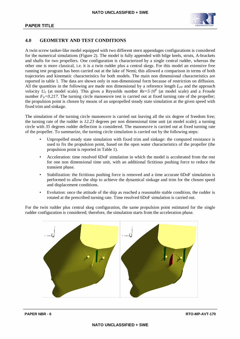
4.0 GEOMETRY AND TEST CONDITIONS
A twin screw tanker-like model equipped with two different stern appendages configurations is considered for the numerical simulations (Figure 2). The model is fully appended with bilge keels, struts, A-brackets and shafts for two propellers. One configuration is characterized by a single central rudder, whereas the other one is more classical, i.e. it is a twin rudder plus a central skegs. For this model an extensive free running test program has been carried out at the lake of Nemi; this allowed a comparison in terms of both trajectories and kinematic characteristics for both models. The main non dimensional characteristics are reported in table 1. The data are shown only in non-dimensional form because of restriction on diffusion. All the quantities in the following are made non dimensional by a reference length LPP and the approach velocity U0 (at model scale). This gives a Reynolds number Re=5∙106 (at model scale) and a Froude number FN=0.217. The turning circle manoeuvre test is carried out at fixed turning rate of the propeller; the propulsion point is chosen by means of an unpropelled steady state simulation at the given speed with fixed trim and sinkage.
The simulation of the turning circle manoeuvre is carried out leaving all the six degree of freedom free; the turning rate of the rudder is 12.23 degrees per non dimensional time unit (at model scale); a turning circle with 35 degrees rudder deflection is considered. The manoeuvre is carried out at fixed turning rate of the propeller. To summarize, the turning circle simulation is carried out by the following steps:
• Unpropelled steady state simulation with fixed trim and sinkage: the computed resistance is used to fix the propulsion point, based on the open water characteristics of the propeller (the propulsion point is reported in Table 1).
• Acceleration: time resolved 6DoF simulation in which the model is accelerated from the rest for one non dimensional time unit, with an additional fictitious pushing force to reduce the transient phase.
• Stabilization: the fictitious pushing force is removed and a time accurate 6DoF simulation is performed to allow the ship to achieve the dynamical sinkage and trim for the chosen speed and displacement conditions.
• Evolution: once the attitude of the ship as reached a reasonable stable condition, the rudder is rotated at the prescribed turning rate. Time resolved 6DoF simulation is carried out.
For the twin rudder plus central skeg configuration, the same propulsion point estimated for the single rudder configuration is considered; therefore, the simulation starts from the acceleration phase.
PAPER TITLE
RTO-MP-AVT-170 PAPER NBR - 7
NATO UNCLASSIFIED + SWE
NATO UNCLASSIFIED + SWE
Figure 2 Configuration: left, single rudder; right, twin rudder plus skeg.
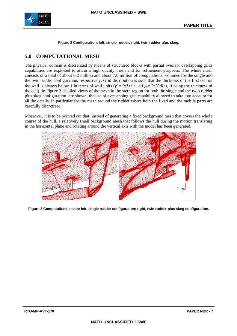
5.0 COMPUTATIONAL MESH
The physical domain is discretized by means of structured blocks with partial overlap; overlapping grids capabilities are exploited to attain a high quality mesh and for refinement purposes. The whole mesh consists of a total of about 6.2 million and about 7.8 million of computational volumes for the single and the twin rudder configuration, respectively. Grid distribution is such that the thickness of the first cell on the wall is always below 1 in terms of wall units (y+=O(1) i.e. /LPP=O(20/Re), being the thickness of the cell). In Figure 3 detailed views of the mesh in the stern region for both the single and the twin rudder plus skeg configuration are shown; the use of overlapping grid capability allowed to take into account for all the details, in particular for the mesh around the rudder where both the fixed and the mobile parts are carefully discretized. Moreover, it is to be pointed out that, instead of generating a fixed background mesh that covers the whole course of the hull, a relatively small background mesh that follows the hull during the motion translating in the horizontal plane and rotating around the vertical axis with the model has been generated.
Figure 3 Computational mesh: left, single rudder configuration; right, twin rudder plus skeg configuration.
PAPER TITLE
PAPER NBR - 8 RTO-MP-AVT-170
NATO UNCLASSIFIED + SWE
NATO UNCLASSIFIED + SWE
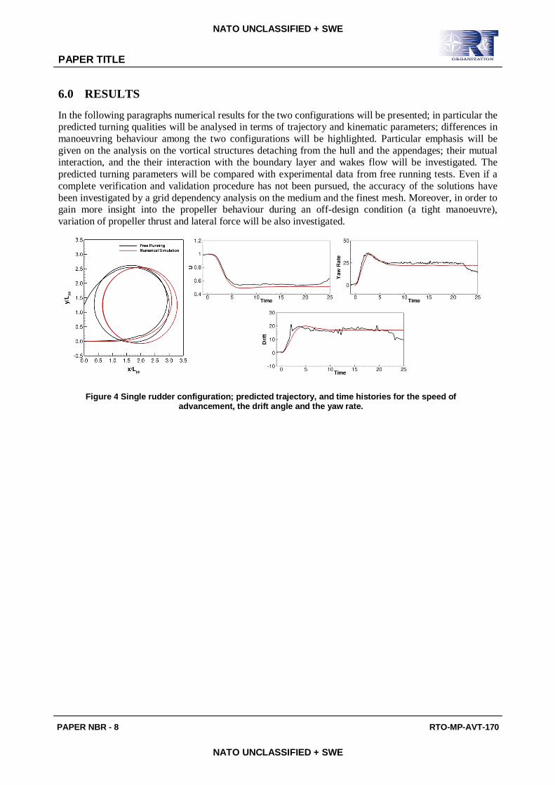
6.0 RESULTS
In the following paragraphs numerical results for the two configurations will be presented; in particular the predicted turning qualities will be analysed in terms of trajectory and kinematic parameters; differences in manoeuvring behaviour among the two configurations will be highlighted. Particular emphasis will be given on the analysis on the vortical structures detaching from the hull and the appendages; their mutual interaction, and the their interaction with the boundary layer and wakes flow will be investigated. The predicted turning parameters will be compared with experimental data from free running tests. Even if a complete verification and validation procedure has not been pursued, the accuracy of the solutions have been investigated by a grid dependency analysis on the medium and the finest mesh. Moreover, in order to gain more insight into the propeller behaviour during an off-design condition (a tight manoeuvre), variation of propeller thrust and lateral force will be also investigated.
Figure 4 Single rudder configuration; predicted trajectory, and time histories for the speed of advancement, the drift angle and the yaw rate.
PAPER TITLE
RTO-MP-AVT-170 PAPER NBR - 9
NATO UNCLASSIFIED + SWE
NATO UNCLASSIFIED + SWE
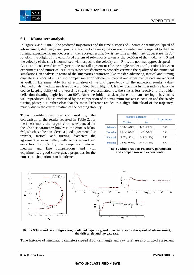
6.1 Manoeuvre analysis In Figure 4 and Figure 5 the predicted trajectories and the time histories of kinematic parameters (speed of advancement, drift angle and yaw rate) for the two configurations are presented and compared to the free running experimental manoeuvres. In the reported results, t=0 is the time at which the rudder starts its 35° rotation, the origin of the earth fixed system of reference is taken as the position of the model at t=0 and the velocity of the ship is normalised with respect to the velocity at t=0, i.e. the nominal approach speed. As it can be observed from Figure 4, the overall agreement (for the single rudder configuration) between experiments and numerical results is rather satisfactory; to properly estimate the quality of the numerical simulations, an analysis in terms of the kinematics parameters like transfer, advancing, tactical and turning diameters is reported in Table 2; comparison error between numerical and experimental data are reported as well. In the same table, for an estimation of the grid dependency for the numerical results, values obtained on the medium mesh are also provided. From Figure 4, it is evident that in the transient phase the course keeping ability of the vessel is slightly overestimated, i.e. the ship is less reactive to the rudder deflection (heading angle less than 90°). After the initial transient phase, the manoeuvring behaviour is well reproduced. This is evidenced by the comparison of the maximum transverse position and the steady turning phase; it is rather clear that the main difference resides in a slight shift ahead of the trajectory, mainly due to the overestimation of the heading stability. These considerations are confirmed by the comparison of the results reported in Table 2: for the finest mesh, the largest error is evidenced for the advance parameter; however, the error is below 6%, which can be considered a good agreement. For transfer, tactical and turning diameters the agreement is even better, with errors around and even less than 3%. By the comparison between medium and fine computations and with experiments, a good convergence properties for the numerical simulations can be inferred.
Figure 5 Twin rudder configuration; predicted trajectory, and time histories for the speed of advancement, the drift angle and the yaw rate.
Time histories of kinematic parameters (speed drop, drift angle and yaw rate) are also in good agreement
Numerical Results
Experiments Medium Fine
Advance 3.33 (16.84%) 3.02 (5.96%) 2.85
Transfer 1.11 (10.00%) 1.02 (2.00%) 1.00
Tactical 2.67 (4.30%) 2.48 (3,13%) 2.56
Turning 2.89 (14.68%) 2.60 (2.44%) 2.52
Table 2 Single rudder: trajectory parameters and comparison with experiments.
PAPER TITLE
PAPER NBR - 10 RTO-MP-AVT-170
NATO UNCLASSIFIED + SWE
NATO UNCLASSIFIED + SWE
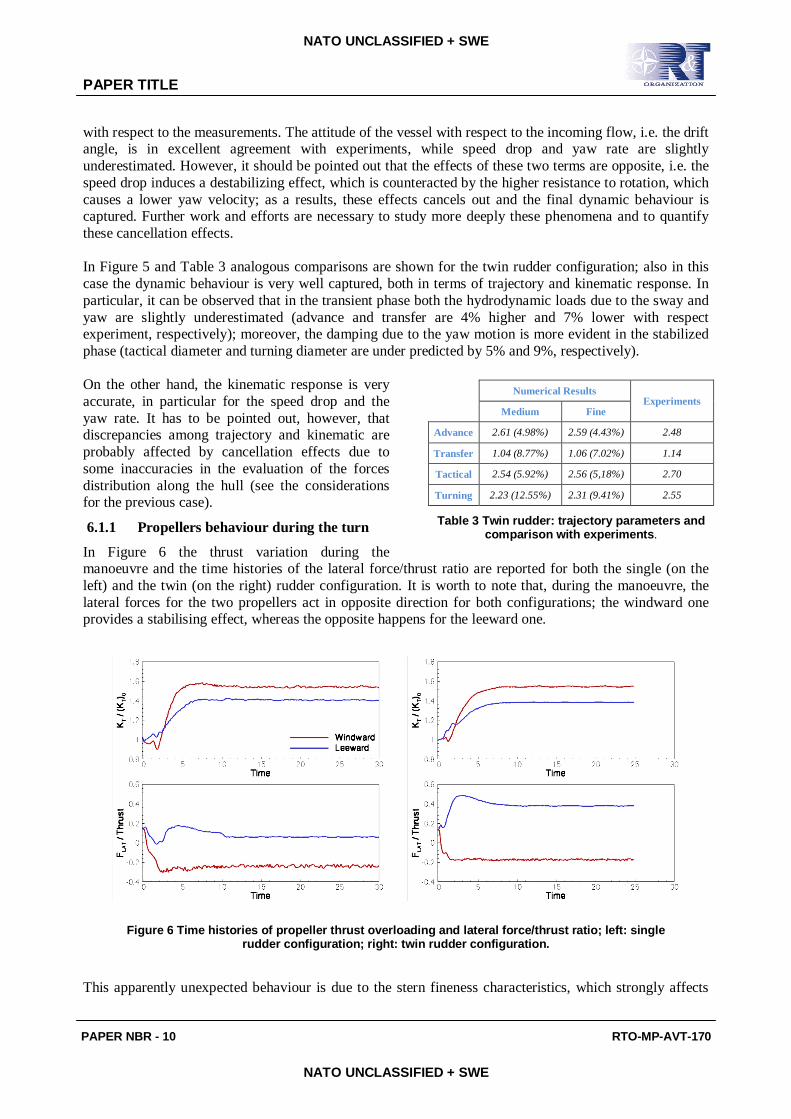
with respect to the measurements. The attitude of the vessel with respect to the incoming flow, i.e. the drift angle, is in excellent agreement with experiments, while speed drop and yaw rate are slightly underestimated. However, it should be pointed out that the effects of these two terms are opposite, i.e. the speed drop induces a destabilizing effect, which is counteracted by the higher resistance to rotation, which causes a lower yaw velocity; as a results, these effects cancels out and the final dynamic behaviour is captured. Further work and efforts are necessary to study more deeply these phenomena and to quantify these cancellation effects. In Figure 5 and Table 3 analogous comparisons are shown for the twin rudder configuration; also in this case the dynamic behaviour is very well captured, both in terms of trajectory and kinematic response. In particular, it can be observed that in the transient phase both the hydrodynamic loads due to the sway and yaw are slightly underestimated (advance and transfer are 4% higher and 7% lower with respect experiment, respectively); moreover, the damping due to the yaw motion is more evident in the stabilized phase (tactical diameter and turning diameter are under predicted by 5% and 9%, respectively). On the other hand, the kinematic response is very accurate, in particular for the speed drop and the yaw rate. It has to be pointed out, however, that discrepancies among trajectory and kinematic are probably affected by cancellation effects due to some inaccuracies in the evaluation of the forces distribution along the hull (see the considerations for the previous case).
6.1.1 Propellers behaviour during the turn
In Figure 6 the thrust variation during the manoeuvre and the time histories of the lateral force/thrust ratio are reported for both the single (on the left) and the twin (on the right) rudder configuration. It is worth to note that, during the manoeuvre, the lateral forces for the two propellers act in opposite direction for both configurations; the windward one provides a stabilising effect, whereas the opposite happens for the leeward one.
Figure 6 Time histories of propeller thrust overloading and lateral force/thrust ratio; left: single rudder configuration; right: twin rudder configuration.
This apparently unexpected behaviour is due to the stern fineness characteristics, which strongly affects
Numerical Results
Experiments Medium Fine
Advance 2.61 (4.98%) 2.59 (4.43%) 2.48
Transfer 1.04 (8.77%) 1.06 (7.02%) 1.14
Tactical 2.54 (5.92%) 2.56 (5,18%) 2.70
Turning 2.23 (12.55%) 2.31 (9.41%) 2.55
Table 3 Twin rudder: trajectory parameters and comparison with experiments.
PAPER TITLE
RTO-MP-AVT-170 PAPER NBR - 11
NATO UNCLASSIFIED + SWE
NATO UNCLASSIFIED + SWE
the local flow field features. In particular, in this case the windward propeller experiences a strong oblique flow from the windward to the leeward side, whereas the leeward propeller experiences an oblique flow in the opposite direction. It has to be emphasized that the global effect of the propellers in case of the twin screw configuration is opposite with respect to the single rudder one: it can be observed that the magnitude of the (destabilizing) lateral force experienced by the internal propeller overcomes the stabilizing effect provided by the external propeller, the global effect acting to improve the turning quality of the vessel, as described above. This different behaviour is mainly due to propeller-rudder interactions, which are absent, or at least negligible, in the single rudder configuration: the rudder behind the propeller induces an up-wash in the propeller plane that increases the lateral component of the propeller inflow, and consequently, the force is greater; on the other hand, in the windward side, the same effect acts to reduce the lateral component of the propeller inflow, resulting in a reduction of the stabilizing force. It has to be pointed out that usually rudder/propeller interactions studies have been centred and focused on the beneficial effect of the propeller on the rudder (because of the energy recovery in the slipstream) in terms of the control forces developed; moreover, rudder induced effects on propeller performance have been often analysed in terms of propulsive effect (rudder blockage), as described extensively in [12][13], i.e. in terms of the effects on thrust and torque coefficients (and on cavitation). The computations here performed on the twin rudder configuration provide a deeper insight of these complex interaction phenomena, emphasizing that the presence of a lifting surface behind the propeller induces an additional, not negligible, force which contributes to the dynamic response of the vessel. It could be observed that, in both cases, after the rudder is rotated, the thrust (and torque, not reported) developed by both propellers increases; this is consequent to the decrease of the advance coefficients, because of the speed reduction experienced by the vessel in the drift-yaw motion. Moreover, this phenomenon is not symmetrical, i.e. the external/windward propeller develops higher loads with respect to the leeward one, because the wake, and consequently the inflow in correspondence of the propeller plane, is asymmetrical.
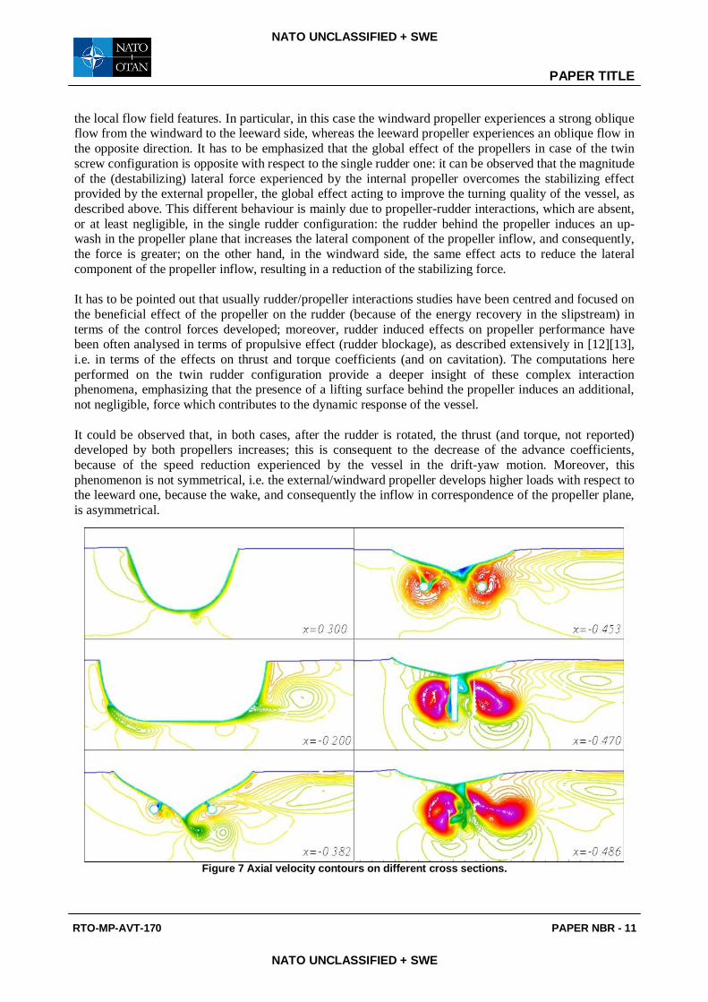
Figure 7 Axial velocity contours on different cross sections.

PAPER TITLE
PAPER NBR - 12 RTO-MP-AVT-170
NATO UNCLASSIFIED + SWE
NATO UNCLASSIFIED + SWE
6.1 Flow Field For the sake of completeness, the longitudinal velocity (during the stabilized phase) on different cross sections along the hull (in the single rudder configuration) is presented in Figure 7. From the velocity field on these sections the complexity of the flow field can be observed; in particular the flow is characterized by vortical structures of different strength which interact with each other and with the boundary layer along the hull. At x=0.3 (bow region) the generation of a clockwise vortex (when seeing from the bow) is observed; this vortex is due to the cross flow around the bulbous bow, the direction of this transversal flow being from the inner to the outer side with respect to the centre of the trajectory (the lateral velocity due to the yaw rate overtakes the drift motion, and therefore the net flux at the bow is from the inner to the outer side); once this vortex is generated, it is driven by the incoming flow, and therefore it is convected toward the port side. At x=-0.2 two counter-clockwise vortices detached from the leeward and windward bilges can be observed. These vortices are convected downstream: the one on the port/leeward side is stronger and it is clearly observable up to the last section x=-0.486. The vortex on the starboard/windward side is convected toward the port side and it merges with the intense keel vortex (see section at x=-0.382); moreover, the windward shaft bossing generates a further vortex, which is convected downstream. At section x=-0.453, the swirl and the acceleration caused by the propellers is shown; the interaction between the wakes of the appendages with the propeller is evident. The flow around the rudder and in its wake is shown in the last two sections from which it can be seen that the rudder is partially in the slipstream of the outer propeller. From the section x=-0.471, it can also be observed that the rudder is in the wake of the skeg, causing a strong inefficiency of the rudder itself. In the last section, flow separation in the suction side of the rudder, as well as tip vortex generated by the cross flow, are evident.
6.0 CONCLUSIONS
The capabilities of CFD techniques for the prediction of the manoeuvring behaviour of a tanker-like vessel equipped with two different stern configurations have been analysed. To this purpose, a finite volume RANS solver that couples the Navier-Stokes equations to the solution of the dynamic equations of rigid body motion have been used. In order to account for the propeller in-plane forces arising during tight manoeuvres, a novel approach has been followed by coupling a generalized actuator disk model with the simplified lateral force model proposed by Ribner.
Comparison with experimental results demonstrate that this component should be considered in order to improve the prediction of the ship manoeuvring performances as well rudder propeller interactions. A description of the flow features has been also presented, with particular emphasis in the stern region.
Further studies and research is needed for gaining more insight into propeller off design conditions, in order to develop simplified and computationally efficient models, which can be included in CFD solvers in order to improve their ability in evaluating ship’s stability and manoeuvring behaviour. Finally, the present computations provide a deeper insight into the complex phenomenon of rudder–propeller interactions in terms of induced propeller loads during tight turns.
AKNOWLEDGEMENTS
The work has been partially financed by the Italian Navy throughout the research project Submotion II. Numerical computations presented here have been performed on the parallel machines of CASPUR Supercomputing Center (Rome); their support is gratefully acknowledged.
REFERENCES
[1] Atsavapranee, P, Miller, R Dai, C, Klamo, J, Fry, D, 2010, “Steady-Turning Experiment and
PAPER TITLE
RTO-MP-AVT-170 PAPER NBR - 13
NATO UNCLASSIFIED + SWE
NATO UNCLASSIFIED + SWE
RANSE Simulations on a Surface Combatant Hull Form (Model #5617)”, 28th ONR Symposium, Pasadena.
[2] Broglia R., Di Mascio A., Amati, G., 2007. “A Parallel Unsteady RANS Code for the Numerical Simulations of Free Surface Flows”, Proc. of 2nd International Conference on Marine Research and Transportation, Ischia, Naples, Italy.
[3] Di Mascio A., Broglia R. Favini, B., 2001, “A second order Godunov-type scheme for naval hydrodynamics, in: Godunov Methods: Theory and Applications”, Kluwer Academic/Plenum Publishers. pp. 253–261.
[4] Di Mascio A., Broglia R. and Muscari R., 2007, “On the application of the single-phase level set method to naval hydrodynamic flows”, Computers & Fluids 36, 868–886.
[5] Di Mascio, A., Broglia, R., and Muscari, R. (2009). “Prediction of hydrodynamic coefficients of ship hulls by high-order Godunov-type methods”. J. Marine Sci. Tech., Vol. 14, pag. 19-29.
[6] Di Mascio A., Dubbioso G., Notaro C., Viviani M., 2011, “Investigation of twin screw naval ships manoeuvring behaviour”, Journal of Ship Research, accepted for publication.
[7] Di Mascio, A., Muscari, R., and Broglia, R. (2006). “An Overlapping Grids Approach for Moving Bodies Problems”. 16th ISOPE, San Francisco, California (USA).
[8] Dubbioso, G., “Manoeuvrability Behaviour of twin screw vessels”, PhD Thesis, Genova University, April 2011.
[9] Durante D., Broglia R., Muscari R. and Di Mascio A., “Numerical simulations of a turning circle maneuver or a fully appended hull”, 28th Symposium on Naval Hydrodynamics, Pasadena (Ca), 12-17 September 2010.
[10] Favini, B., Broglia, R., and Di Mascio, A. (1996). “Multigrid Acceleration of Second Order ENO Schemes from Low Subsonic to High Supersonic Flows”. Int. J. Num. Meth. Fluids, vol. 23, pag. 589-606.
[11] Hough G.R. and Ordway D.E., “The generalized actuator disk”, Developments in Theoretical and Applied Mechanics, 2:, pag. 317-336, 1965.
[12] Molland A.F., Turnock S.R., “Marine Rudders and Control Surfaces”, Butterworth-Heinemann, 2006.
[13] Phillips A.B., Turnock S.R., Furlong M.E., “Accurate Capture of Rudder-Propeller Interactions using a coupled Blade Element–RANS Approach”, 12th Numerical Towing Tank Conference, 2009.
[14] Ribner, H.S, “Propeller in yaw”, NACA TECHNICAL REPORT 3L09, 1943.
[15] Spalart P.R. and Allmaras S.R., “A One-Equation Turbulence Model for Aerodynamic Flows”, La Recherche Aerospatiale 1 (1994) 5-21.
[16] Stern, F. and Agdrup, K. (2008). Proceedings of Workshop on Verification and Validation of Ship Manoeuvering Simulation Methods, Copenhagen, Denmark.
[17] Stern F., Agdrup K., Kim S.Y., Cura-Hochbaum A., Rhee K.P., Quadvlieg F., Perdon P., Hino T., Broglia R., Gorski J., “Experience from SIMMAN 2008 - The first workshop on verification and validation of ship manoeuvring simulation methods”, Journal of Ship Research, Vol. 55, No. 2, June 2011, pp. 135–147.
[18] Viviani M., Dubbioso G., Soave M., Notaro C., Depascale R., “Hydrodynamic coefficients regressions analysis and application to twin screw naval vessels”, IMAM 2009, Istanbul.