Embed Size (px)
Citation preview

Prediction of Bus Arrival Time Using
GPS/GSM Technology
Submitted in partial fulfillment of the requirements
for the degree of
Bachelor of Engineering
By
Khan Salman Aafak
Khan Umair Abdul Shakur
Khan Mehfooz Ahmed Mohd Feroz
Khan Mohammed Ahmed Abdul Hameed
Under the guidance of
Prof. Siraj Pathan
Department Electronics and Telecommunication Engineering
Anjuman-i-Islam's Kalsekar Technical Campus
New Panvel
2015-2016
ii
Project Report Approval for B. E.
This project report entitled Prediction of Bus Arrival Time Using
GPS/GSM Technology by Khan Salman Aafak , Khan Umair Abdul
Shakur , Khan Mehfooz Ahmed Mohd Feroz , Khan Mohammed
Ahmed Abdul Hameed is approved for the degree of Electronics and
Telecommunication Engineering.
Examiner
---------------------------------------------
Supervisor
---------------------------------------------
Head of Department
-----------------------------------------------
Date:
Place:
iii
DECLARATION
I declare that this written submission represents my ideas in my own words
and where others' ideas or words have been included, I have adequately cited
and referenced the original sources. I also declare that I have adhered to all
principles of academic honesty and integrity and have not misrepresented or
fabricated or falsified any idea/data/fact/source in my submission. I understand
that any violation of the above will be cause for disciplinary action by the
Institute and can also evoke penal action from the sources which have thus not
been properly cited or from whom proper permission has not been taken when
needed.
Name of Students Signatures
Khan Salman Aafak : ------------------------------------
Khan Umair Abdul Shakur : ------------------------------------
Khan Mehfooz Ahmed Mohd Feroz : ------------------------------------
Khan Mohammed Ahmed Abdul Hameed : ------------------------------------
Date:
iv
CERTIFICATE
This is to certify that the project entitled “ Prediction of Bus Arrival
Time Using GPS/GSM Technology” is the bonafide work carried out by B.E.
Electronics and Telecommunication students of Kalsekar Technical
Campus, Panvel , during the year 2015-2016, in partial fulfillment of the
requirements for the award of the Degree of B.E. in Electronics And
Telecommunication and that the project has not formed the basis for the award
previously of any degree, diploma, associate ship, fellowship or any other
similar title.
_________________________ __________________________
(Prof.Mujib Tamboli) (Prof. Siraj Pathan)
H.O.D EXTC Project Guide
__________________
(External Examiner)
v
ACKNOWLEDGMENT
I am greatly indebted to almighty God for the attribute blessing to me without
which the work was impossible. It is also impossible to complete successfully a
project without the genuine co-operation of others. Many people have
contributes to the successful completion of this project. I would like to place on
record my grateful thanks to each of them and the report would be incomplete
without giving due credits them.
I feel extremely exhilarated to have completed project under inspiring guidance
of Prof.Siraj Pathan. His masterly guidance and timely encouragement infused
courage in us to complete the work successfully. I would not be exaggerating if
say than he even altered my way of thinking and functioning. My profound
thanks are due to his.
I am highly obliged to Dr. Abdul Razak Honnutagi , Director, Anjuman-I-
Islam’s Kalsekar Technical campus School of Engineering, Mumbai and
Prof.Mujib Tamboli, HOD, department of Electronicsand
Telecommunication for providing facilities required for our project.
Last but not the least, I would like to thanks all the other staff members, my
friends for their advice, support and suggestions to make this project work come
to reality.
By
Khan Umair Abdul Shakur Khan Mehfooz Ahmed Mohd Feroz
Roll No: 11ET28 Roll No: 11ET24
Khan Salman Aafak Khan Mohammed Ahmed Abdul Hameed
Roll No: 11ET27 Roll No: 11ET13

vi
PREFACE
We take great opportunity to present this project report on “Prediction of
Bus Arrival Time Using GPS/GSM Technology” & put before readers some
useful information regarding our project.
We have made sincere attempts & taken every care to present this matter
in precise & compact form, the language being as simple as possible.
We are sure that the information contained in this volume would certainly
prove useful for better insight in the scope & dimension of this project in its true
perspective.
The task of completion of the project though being difficulty was made quite
simple, interesting & successful due to deep involvement & complete dedication
of our group members.
vii
CONTENTS
Certificate
Acknowledgement
Preface
Abstract
List of Tables
List of Figures
Chapter 1. Introduction 1
1.1 Motivation
1.2 Objective
Chapter 2. Review of Literature 4
Chapter 3. Overview of the Devices used 7
3.1 UBlox Neo-6M
3.1.1 Features of Neo-6M GPRS
3.2 SIM 900A
3.2.1Features of SIM 900A
3.3 Arduino Uno
3.3.1 features of Arduino Uno R3
3.4 Software Module
3.4.1 Arduino IDE
3.4.2 U-Center
Chapter 4. System Design 16
4.1 System Model
4.2 Working of System Model
4.2.1 Overall Function
4.3 Detailed Working
viii
4.3.1 Real time GPS Tracker unit
4.3.2 Displaying unit at Bus stop
4.3.2.2 Writing commands in LCD with Arduino Board
4.3.2.4 Algorithm for checking the SIM 900A using PC
4.3.3 Server and Data Base
Chapter 5. Results and Discussion 25
Chapter 6. Conclusion Future Scope 28
6.1 Conclusion
6.2 Future Scope
Chapter 7. Reference 30
Appendix I 32
Appendix II 36
Appendix III 38
Appendix IV 39
ix
ABSTRACT
In the daily operation of a bus system, the movement of vehicles is
affected by uncertain conditions as the day progresses, such as traffic
congestion, unexpected delays, and randomness in passenger demand, irregular
vehicle dispatching times, and incidents. It often discourages the passengers for
excessively waiting long time at bus stops and makes them reluctant to take the
public transport, buses.
In this project we propose a system by which we can predict bus
arrival time using GPS and GSM technology. It is an embedded system using
GPS (Global Positioning System), GSM (Global System for Mobile
Communication) and Arduino for tracking the bus. The real time co-ordinates
obtained from the GPS will continuously monitor a moving vehicle and report
the status of the vehicle on request to passengers. The GPS/GSM unit is
mounted on the bus sends the data to the central monitoring system using the
GSM module. The position i.e. Latitude and Longitude of a vehicle from remote
place is sent by the GSM module to the Server and then the server calculates the
arrival time of the bus and sends to the LCD Module mounted at bus stop
through GSM module.
x
LIST OF TABLES
Table 4.1 Interfacing GPS/Arduino 19
Table 4.2 Interfacing GSM/Arduino 19
Table 4.3 Interfacing LCD/Arduino 20
Table 4.4 Interfacing GSM/Arduino 21
Table 4.5: gmaptracker MySQL database 24
xi
LIST OF FIGURES
Figure 3.1: UBlox Neo-6M GPS Module 8
Figure 3.2: Neo-6M Pin layout 9
Figure 3.3: SIM900A GSM Module 10
Figure : SIM900A pin layout 11
Figure 3.4: Arduino Uno R3 12
Figure 3.5: u-center start-up display 15
Figure 4.1a: System model 17
Figure 4.1b: System model 17
Figure 4.2: Transferring positional data to server 22
Figure 4.3: Data accessing process 23
Figure 5.1: Received GPS data 26
Figure 5.2: Real Time GPS Tracker Unit 27
Figure 5.3: Displaying Unit at Bus Stop 27
xii
ACRONYMS
GPS – Global Positioning System
GSM – Global System for Mobile Communication
GPRS – General Packet Radio Service
LCD – Liquid Crystal Display
ATmega32- Atmel 8-bit AVR RISC based microcontroller
TCP – Transmission Control Protocol

Chapter 1
INTRODUCTION
2
1. Introduction
Public transport, especially the bus transport, has been well developed in many parts of
the world. The bus transport services reduce the private car usage and fuel consumption, and
alleviate traffic congestion. As one of the most comprehensive and affordable means of
public transport.
When traveling with buses, the travelers usually want to know the accurate arrival time of
the bus. Excessively long waiting time at bus stops may drive away the anxious travelers and
make them reluctant to take buses. Nowadays, most bus operating companies have been
providing their timetables on the web freely available for the travelers. The bus timetables,
however, only provide very limited information (e.g., operating hours, time intervals, etc.),
which are typically not timely updated. Other than those official timetables, many public
services (e.g., Google Maps) are provided for travelers. Although such services offer useful
information, they are far from satisfactory to the bus travelers. For example, the schedule of a
bus may be delayed due to many unpredictable factors (e.g., traffic conditions, harsh weather
situation, etc). The accurate arrival time of next bus will allow travelers to take alternative
transport choices instead, and thus mitigate their anxiety and improve their experience.
Towards this aim, many commercial bus information providers offer the real time bus arrival
time to the public. Providing such services, however, usually requires the cooperation of the
bus operating companies (e.g., installing special location tracking devices on the buses), and
incurs substantial cost.
1.1 Motivation
The commuters which travel through public transport vehicle often faces the decision
of whether it would quicker to wait for the next bus or to take other vehicle to reach his/her
destination. Many people are often late to their work because they decide to wait for bus
instead taking other mean of transportation vehicle. This situation motivate us to design a
system which is capable to predict accurate the bus arrival time therefore we select this
project.
3
1.2 Objective
The objective of this project is to design an embedded system which is used for
tracking and positioning of any vehicle by using Global Positioning System (GPS) and
Global system for mobile communication (GSM). A combination of computer hardware and
software, and perhaps additional mechanical part designed to perform a specific function is
known as an Embedded System. An embedded system is software driven, real-time control
system, microcontroller-based, reliable, human or network interactive, autonomous, operating
on diverse physical variables and in diverse environments and sold into a competitive and
cost conscious market. The quality of life in every society can be contributed by effective
movement of people and goods which is lead by the efficient transportation system.

4
Chapter 2
Review of Literature
5
2. Review of Literature
A number of studies have been initiated in the past to address the bus arrival time
prediction problem. One study has shown that Prediction of bus arrival time is simply
implemented using GPS and GSM module. In this system The GPS is used to locate the
position of the bus it will send the data to the server through SMS using GSM module. When
the request by user is sent to the number at the modem, the server system calculate the time
the vehicle may take to reach the corresponding user bus stop and automatically sends a
return reply to that mobile indicating the time.[1]
One study has shown that bus arrival time can be predicted based on their historical
data. This system comprises of GPS. Each bus has its unique GPS id. Bus number, bus
running route , bus direction all these information is feed into GPS id. When passenger states
requests for the bus number, source, destination of the bus, from this information we can
interpret the bus service route and the direction of the bus. The transit vehicles running on
that route are determined by the respective global positioning system (GPS) id. This GPS id
has information stored in the database After the information that is given by the passenger is
matched and a list of buses that come under that route are found and displayed.[2]
Pengfei Zhou (2014) predict the bus arrival time with mobile phone based
participatory sensing. They divided the whole system into three parts Querying User ,
Sharing User and Backend Server. A querying user queries the bus arrival time by sending
the request to the backend server. The querying user indicates the interest bus route and bus
stop to receive the predicted bus arrival time. The sharing user on the other hand contributes
the mobile phone sensing information to the system. After a sharing user gets on a bus, the
data collection module starts to collect a sequence of nearby cell tower IDs. The collected
data is transmitted to the server via cellular networks. Most of the computation burden are
shift to the backend server where the uploaded information from sharing users is processed
and the requests from querying users are addressed. The backend server processes the cell
tower sequences from sharing users in the online processing stage. Receiving the uploaded
information, the backend server first classifies the uploaded bus routes primarily with the
reported cell tower sequence information. The bus arrival time on various bus stops is then
derived based on the current bus route statuses. [3]
6
Dynamic Bus time table is another system to predict the bus arrival time. The system
is divide into three model Android application, remote database and website. Android
application is use for getting the current location of bus. The main work of application is get
current location of bus and send to remote database. It contains Admin, Bus Conductor and
user side. Admin control the timetables of all buses. Only admin can add or removing the bus
from timetable. Admin can assign a unique id for route so bus conductor can access it. Bus
conductor also had his personal id and password. Main work of bus conductor is selecting the
bus route and start application when bus is ready to go. If user used this application then they
can see only timetable of required buses. [4]
While the studies provide valuable information regarding prediction of bus arrival
time. The first system uses sms to provide the expected arrival time. But the limitation of the
system is that most passenger does not know the modem mobile number to get the ETA time.
The other system uses historical base prediction. Which is incapable to provide accurate time
because the condition may not same for all days such as traffic, weather etc. Some system
need some manual setting to predict the bus arrival time.
In this project we proposed system which is automated and more reliable to access the
system. Our system uses GPS to get the current location of bus. This information is
transmitted to server using GPRS. The server perform calculation to get the expected arrival
time of bus. The server send the ETA to displaying unit which is install to bus stop. This
displaying unit help the passenger which does not know our website. The server also provide
service to website user. So many passenger can manage their valuable time.
7
Chapter 3
Overview of the Devices used
8
3. Overview of the Devices used
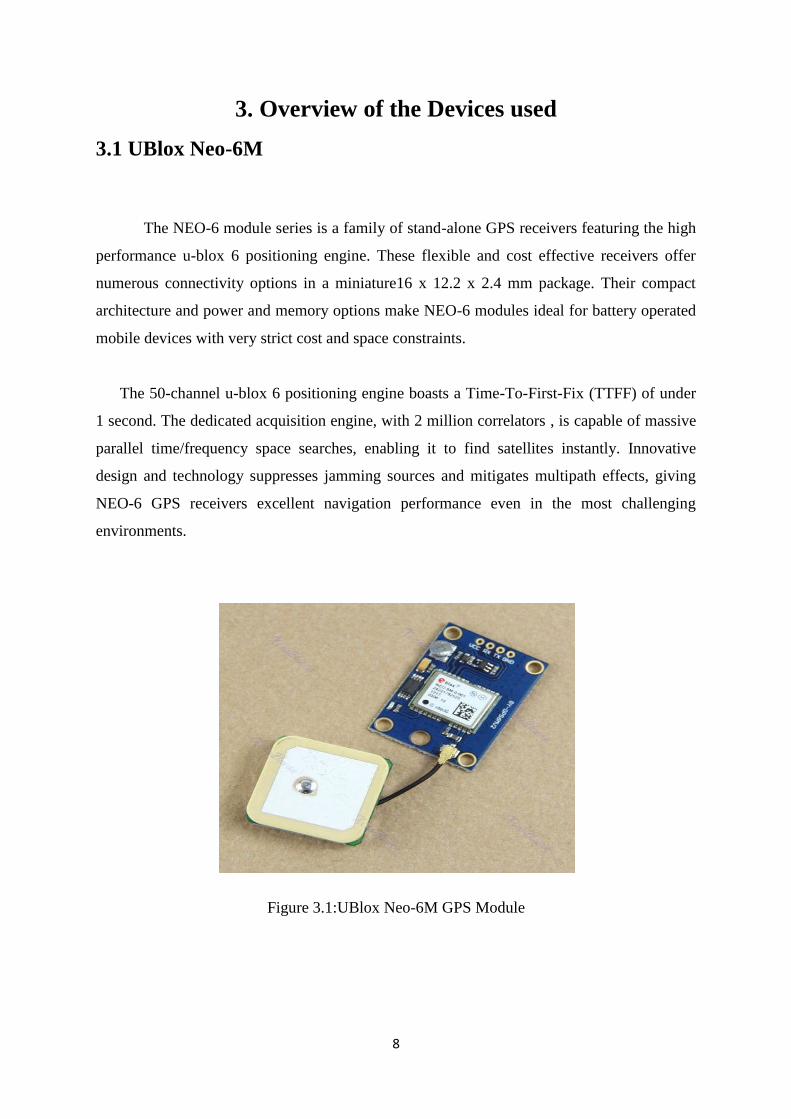
3.1 UBlox Neo-6M
The NEO-6 module series is a family of stand-alone GPS receivers featuring the high
performance u-blox 6 positioning engine. These flexible and cost effective receivers offer
numerous connectivity options in a miniature16 x 12.2 x 2.4 mm package. Their compact
architecture and power and memory options make NEO-6 modules ideal for battery operated
mobile devices with very strict cost and space constraints.
The 50-channel u-blox 6 positioning engine boasts a Time-To-First-Fix (TTFF) of under
1 second. The dedicated acquisition engine, with 2 million correlators , is capable of massive
parallel time/frequency space searches, enabling it to find satellites instantly. Innovative
design and technology suppresses jamming sources and mitigates multipath effects, giving
NEO-6 GPS receivers excellent navigation performance even in the most challenging
environments.
Figure 3.1:UBlox Neo-6M GPS Module
9
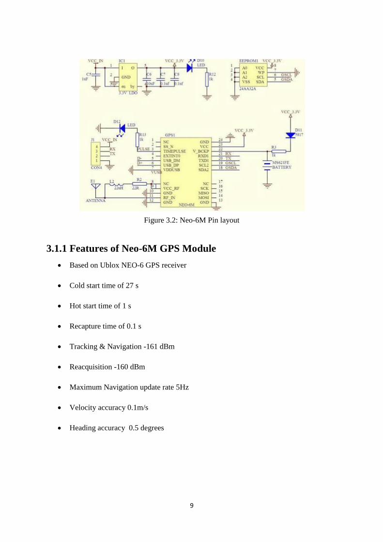
Figure 3.2: Neo-6M Pin layout
3.1.1 Features of Neo-6M GPS Module
Based on Ublox NEO-6 GPS receiver
Cold start time of 27 s
Hot start time of 1 s
Recapture time of 0.1 s
Tracking & Navigation -161 dBm
Reacquisition -160 dBm
Maximum Navigation update rate 5Hz
Velocity accuracy 0.1m/s
Heading accuracy 0.5 degrees
10
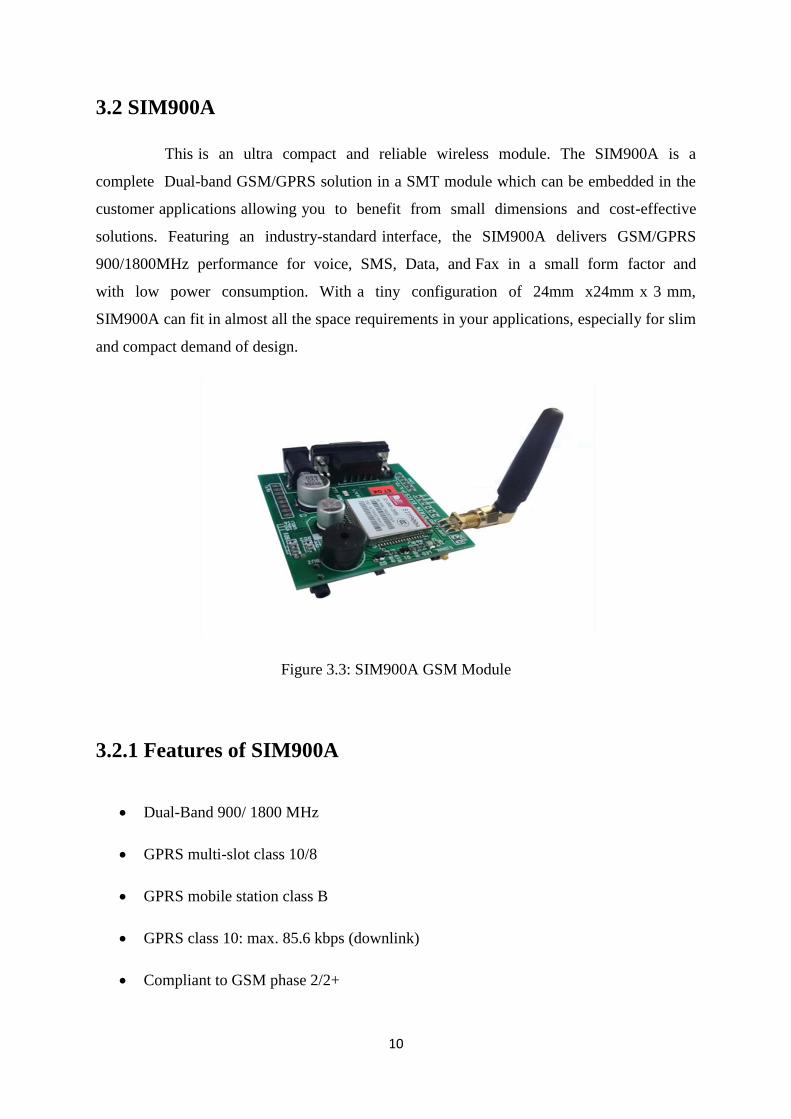
3.2 SIM900A
This is an ultra compact and reliable wireless module. The SIM900A is a
complete Dual-band GSM/GPRS solution in a SMT module which can be embedded in the
customer applications allowing you to benefit from small dimensions and cost-effective
solutions. Featuring an industry-standard interface, the SIM900A delivers GSM/GPRS
900/1800MHz performance for voice, SMS, Data, and Fax in a small form factor and
with low power consumption. With a tiny configuration of 24mm x24mm x 3 mm,
SIM900A can fit in almost all the space requirements in your applications, especially for slim
and compact demand of design.
Figure 3.3: SIM900A GSM Module
3.2.1 Features of SIM900A
Dual-Band 900/ 1800 MHz
GPRS multi-slot class 10/8
GPRS mobile station class B
GPRS class 10: max. 85.6 kbps (downlink)
Compliant to GSM phase 2/2+
11
Class 4 (2 W @900 MHz)
Class 1 (1 W @ 1800MHz)
Control via AT commands (GSM 07.07, 07.05 and SIMCOM enhanced AT
Commands)
Supply voltage range: 3.1- 4.8V
Low power consumption: 1.5mA(sleep mode)
Operation temperature: -40° C to +85°C
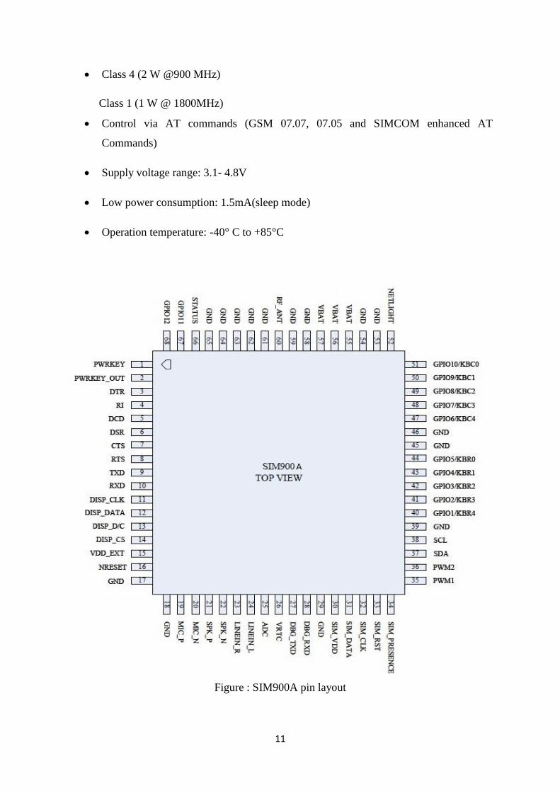
Figure : SIM900A pin layout
12
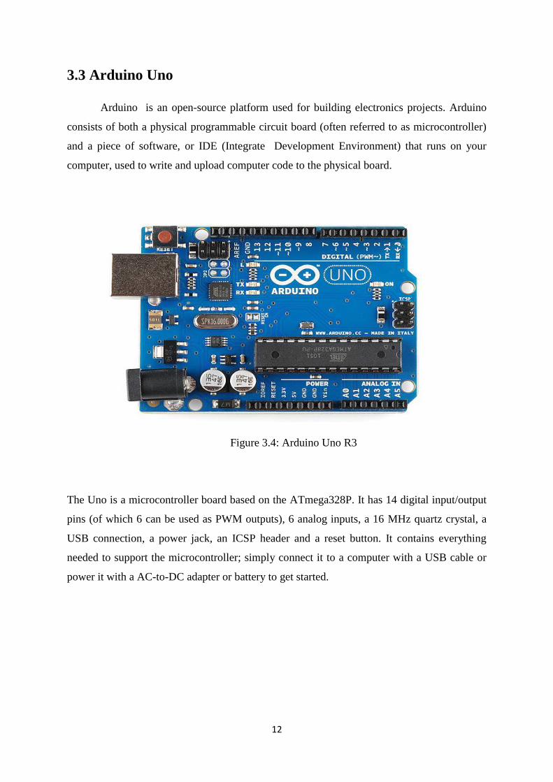
3.3 Arduino Uno
Arduino is an open-source platform used for building electronics projects. Arduino
consists of both a physical programmable circuit board (often referred to as microcontroller)
and a piece of software, or IDE (Integrate Development Environment) that runs on your
computer, used to write and upload computer code to the physical board.
Figure 3.4: Arduino Uno R3
The Uno is a microcontroller board based on the ATmega328P. It has 14 digital input/output
pins (of which 6 can be used as PWM outputs), 6 analog inputs, a 16 MHz quartz crystal, a
USB connection, a power jack, an ICSP header and a reset button. It contains everything
needed to support the microcontroller; simply connect it to a computer with a USB cable or
power it with a AC-to-DC adapter or battery to get started.
13
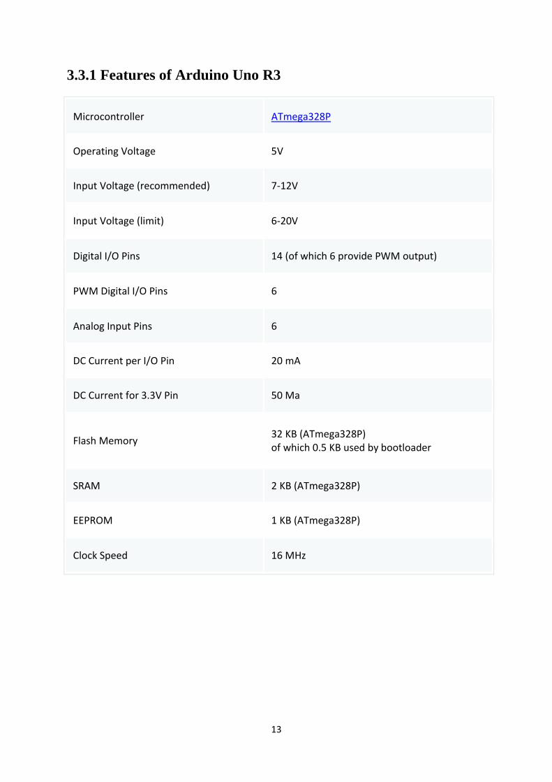
3.3.1 Features of Arduino Uno R3
Microcontroller ATmega328P
Operating Voltage 5V
Input Voltage (recommended) 7-12V
Input Voltage (limit) 6-20V
Digital I/O Pins 14 (of which 6 provide PWM output)
PWM Digital I/O Pins 6
Analog Input Pins 6
DC Current per I/O Pin 20 mA
DC Current for 3.3V Pin 50 Ma
Flash Memory 32 KB (ATmega328P) of which 0.5 KB used by bootloader
SRAM 2 KB (ATmega328P)
EEPROM 1 KB (ATmega328P)
Clock Speed 16 MHz
14
3.4 Software Module
3.4.1 Arduino IDE
The Program is written in Arduino IDE. The Arduino integrated development
environment (IDE) is a cross-platform application written in Java, and derives from the IDE
for the Processing programming language and the Wiring projects. It is designed to introduce
programming to artists and other newcomers unfamiliar with software development.
It includes a code editor with features such as syntax highlighting, brace matching,
and automatic indentation, and is also capable of compiling and uploading programs to the
board with a single click. A program or code written for Arduino is called a sketch.
The program is written in Arduino IDE text editor.After that the code is verified using
IDE. The console displays text output by the Arduino Software (IDE), including complete
error messages and other information.The verified code is uploaded into Arduino Uno R3
Board using serial communication.
15
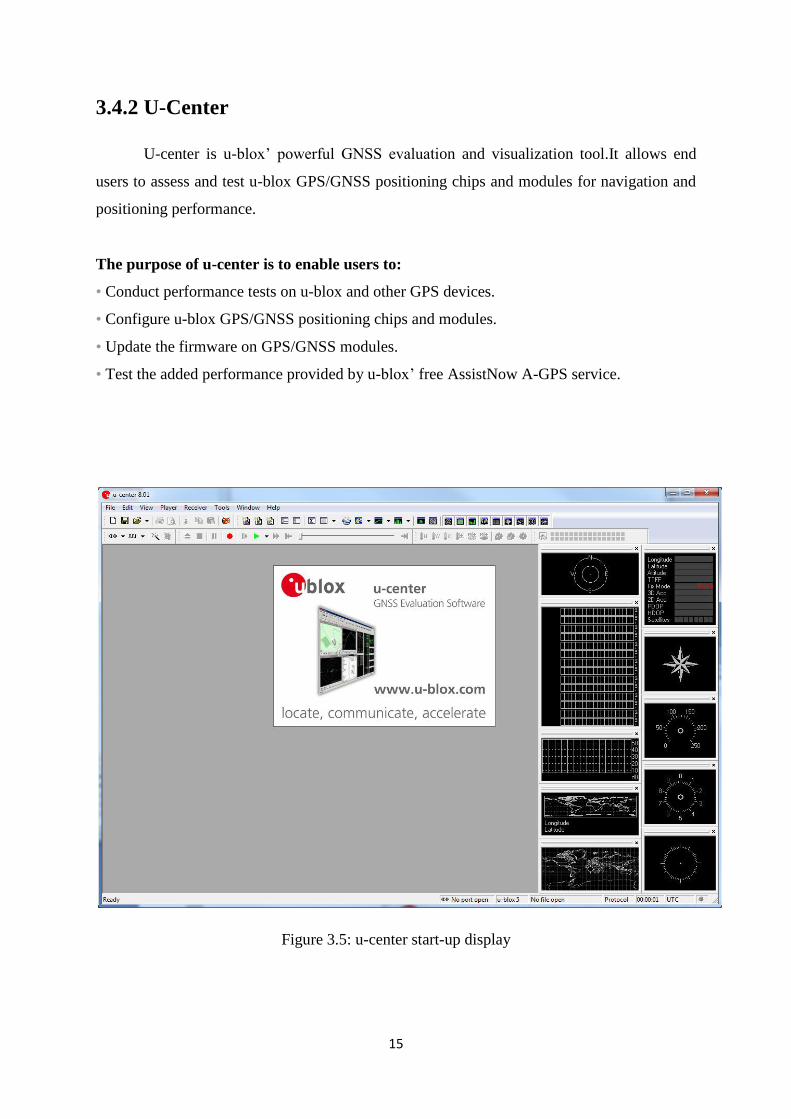
3.4.2 U-Center
U-center is u-blox‟ powerful GNSS evaluation and visualization tool.It allows end
users to assess and test u-blox GPS/GNSS positioning chips and modules for navigation and
positioning performance.
The purpose of u-center is to enable users to:
• Conduct performance tests on u-blox and other GPS devices.
• Configure u-blox GPS/GNSS positioning chips and modules.
• Update the firmware on GPS/GNSS modules.
• Test the added performance provided by u-blox‟ free AssistNow A-GPS service.
Figure 3.5: u-center start-up display

16
Chapter 4
System Design
17
4. System Design
4.1 System Model
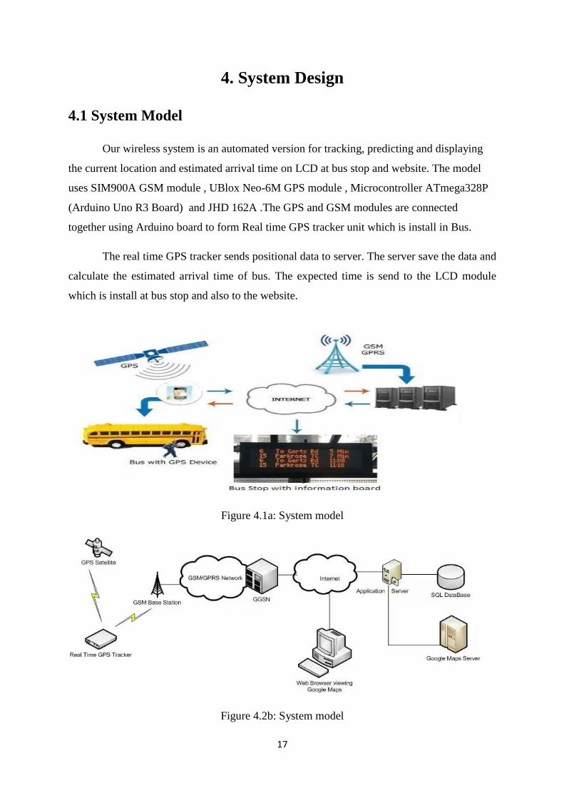
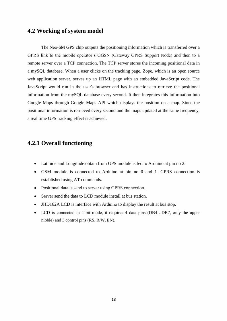
Our wireless system is an automated version for tracking, predicting and displaying
the current location and estimated arrival time on LCD at bus stop and website. The model
uses SIM900A GSM module , UBlox Neo-6M GPS module , Microcontroller ATmega328P
(Arduino Uno R3 Board) and JHD 162A .The GPS and GSM modules are connected
together using Arduino board to form Real time GPS tracker unit which is install in Bus.
The real time GPS tracker sends positional data to server. The server save the data and
calculate the estimated arrival time of bus. The expected time is send to the LCD module
which is install at bus stop and also to the website.
Figure 4.1a: System model
Figure 4.2b: System model
18
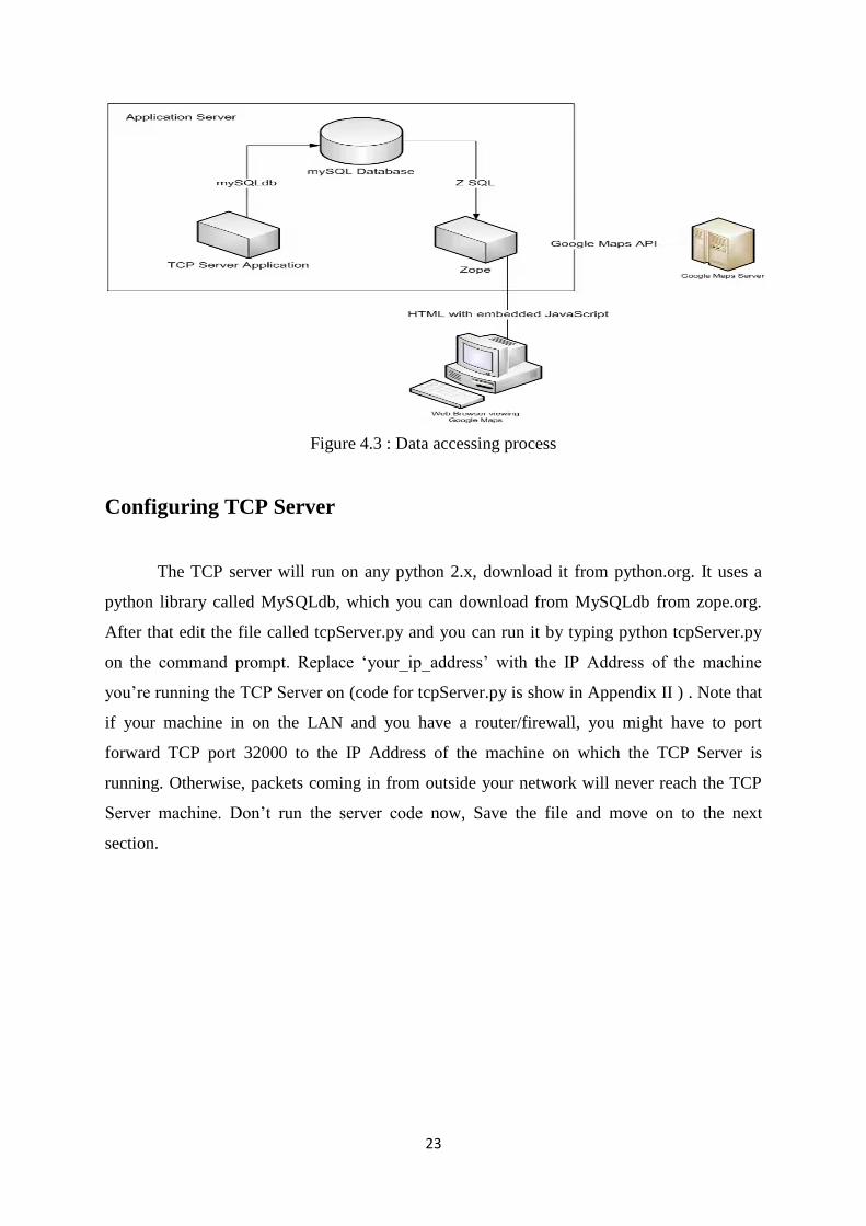
4.2 Working of system model
The Neo-6M GPS chip outputs the positioning information which is transferred over a
GPRS link to the mobile operator‟s GGSN (Gateway GPRS Support Node) and then to a
remote server over a TCP connection. The TCP server stores the incoming positional data in
a mySQL database. When a user clicks on the tracking page, Zope, which is an open source
web application server, serves up an HTML page with an embedded JavaScript code. The
JavaScript would run in the user's browser and has instructions to retrieve the positional
information from the mySQL database every second. It then integrates this information into
Google Maps through Google Maps API which displays the position on a map. Since the
positional information is retrieved every second and the maps updated at the same frequency,
a real time GPS tracking effect is achieved.
4.2.1 Overall functioning
Latitude and Longitude obtain from GPS module is fed to Arduino at pin no 2.
GSM module is connected to Arduino at pin no 0 and 1 .GPRS connection is
established using AT commands.
Positional data is send to server using GPRS connection.
Server send the data to LCD module install at bus station.
JHD162A LCD is interface with Arduino to display the result at bus stop.
LCD is connected in 4 bit mode, it requires 4 data pins (DB4…DB7, only the upper
nibble) and 3 control pins (RS, R/W, EN).
19
4.3 Detailed Working
This section will describe configuration of server , database and differnt Arduino pins
which are used for interfacing different module to Predict the bus arrival time. The Overall
system is divided into Three parts.
1) Real Time GPS Tracker unit
2) Displaying unit at Bus stop
3) Server and Database
4.3.1 Real Time GPS Tracker unit
Real Time GPS Tracking unit is built by interfacing Neo-6M GPS module and
SIM900A GSM module with Arduino board.
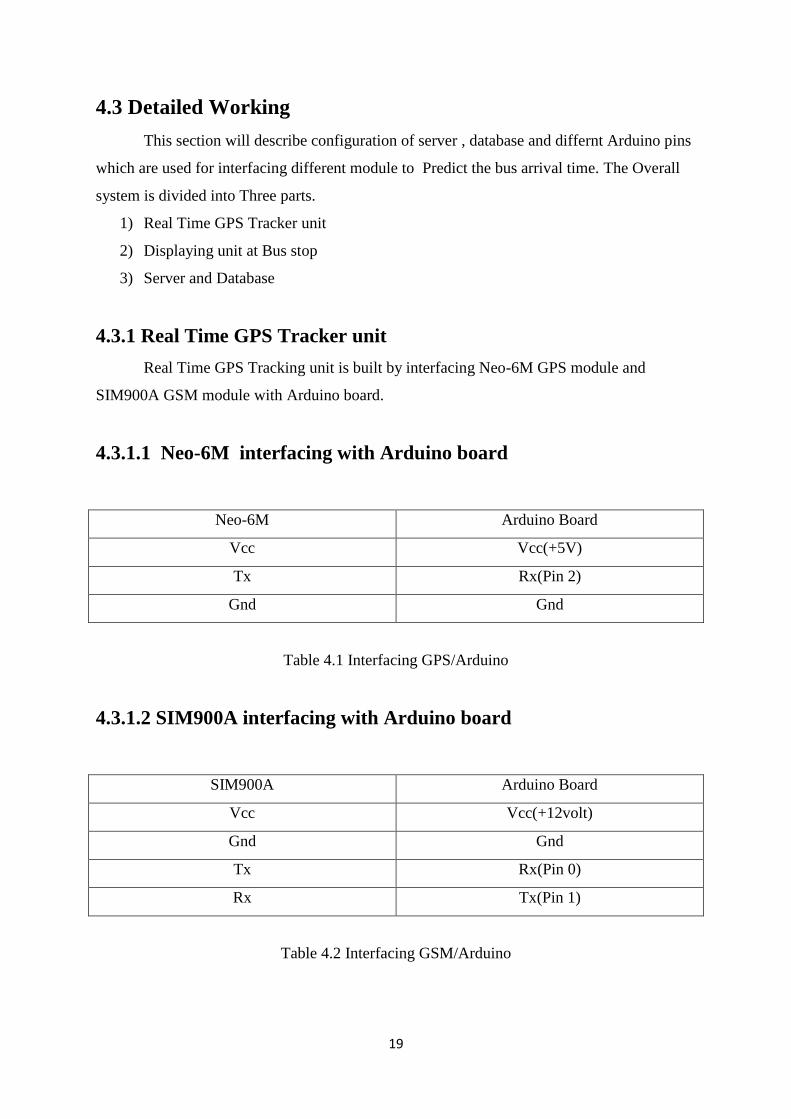
4.3.1.1 Neo-6M interfacing with Arduino board
Neo-6M Arduino Board
Vcc Vcc(+5V)
Tx Rx(Pin 2)
Gnd Gnd
Table 4.1 Interfacing GPS/Arduino
4.3.1.2 SIM900A interfacing with Arduino board
SIM900A Arduino Board
Vcc Vcc(+12volt)
Gnd Gnd
Tx Rx(Pin 0)
Rx Tx(Pin 1)
Table 4.2 Interfacing GSM/Arduino
20
4.3.2 Displaying unit at Bus stop
Displaying unit which is install at bus stop to display the expected bus arrival time of
various buses at that bus stop. This unit is made by interfacing JHD 162A LCD module and
SIM900A GSM module with Arduino board.
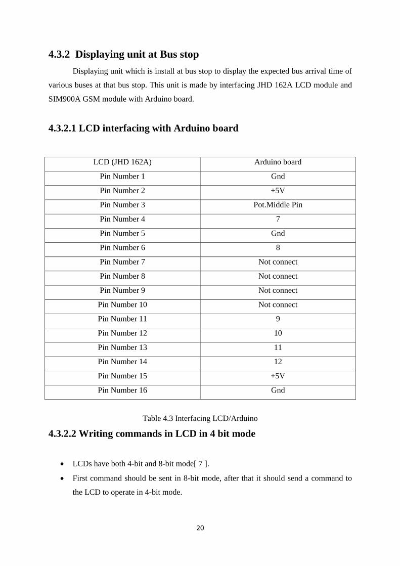
4.3.2.1 LCD interfacing with Arduino board
LCD (JHD 162A) Arduino board
Pin Number 1 Gnd
Pin Number 2 +5V
Pin Number 3 Pot.Middle Pin
Pin Number 4 7
Pin Number 5 Gnd
Pin Number 6 8
Pin Number 7 Not connect
Pin Number 8 Not connect
Pin Number 9 Not connect
Pin Number 10 Not connect
Pin Number 11 9
Pin Number 12 10
Pin Number 13 11
Pin Number 14 12
Pin Number 15 +5V
Pin Number 16 Gnd
Table 4.3 Interfacing LCD/Arduino
4.3.2.2 Writing commands in LCD in 4 bit mode
LCDs have both 4-bit and 8-bit mode[ 7 ].
First command should be sent in 8-bit mode, after that it should send a command to
the LCD to operate in 4-bit mode.
21
Since pin 7-10 are connected to ground on the LCD panel, we must use the 4-bit
communication mode.
The LCD defaults to 8-bit mode.
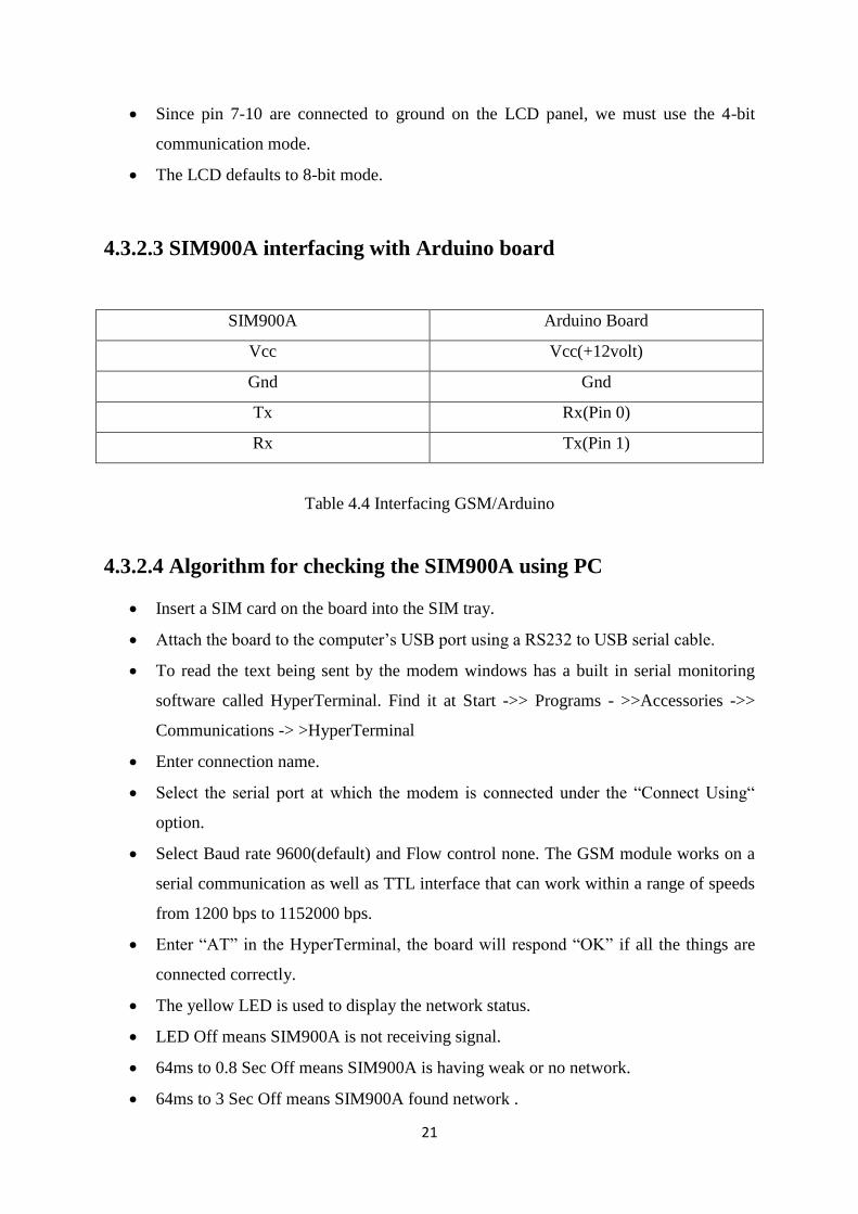
4.3.2.3 SIM900A interfacing with Arduino board
SIM900A Arduino Board
Vcc Vcc(+12volt)
Gnd Gnd
Tx Rx(Pin 0)
Rx Tx(Pin 1)
Table 4.4 Interfacing GSM/Arduino
4.3.2.4 Algorithm for checking the SIM900A using PC
Insert a SIM card on the board into the SIM tray.
Attach the board to the computer‟s USB port using a RS232 to USB serial cable.
To read the text being sent by the modem windows has a built in serial monitoring
software called HyperTerminal. Find it at Start ->> Programs - >>Accessories ->>
Communications -> >HyperTerminal
Enter connection name.
Select the serial port at which the modem is connected under the “Connect Using“
option.
Select Baud rate 9600(default) and Flow control none. The GSM module works on a
serial communication as well as TTL interface that can work within a range of speeds
from 1200 bps to 1152000 bps.
Enter “AT” in the HyperTerminal, the board will respond “OK” if all the things are
connected correctly.
The yellow LED is used to display the network status.
LED Off means SIM900A is not receiving signal.
64ms to 0.8 Sec Off means SIM900A is having weak or no network.
64ms to 3 Sec Off means SIM900A found network .
22
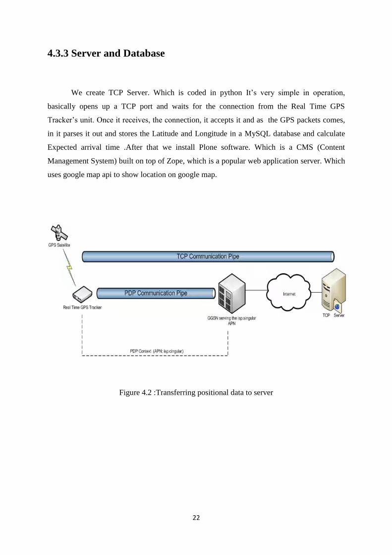
4.3.3 Server and Database
We create TCP Server. Which is coded in python It‟s very simple in operation,
basically opens up a TCP port and waits for the connection from the Real Time GPS
Tracker‟s unit. Once it receives, the connection, it accepts it and as the GPS packets comes,
in it parses it out and stores the Latitude and Longitude in a MySQL database and calculate
Expected arrival time .After that we install Plone software. Which is a CMS (Content
Management System) built on top of Zope, which is a popular web application server. Which
uses google map api to show location on google map.
Figure 4.2 :Transferring positional data to server
23
Figure 4.3 : Data accessing process
Configuring TCP Server
The TCP server will run on any python 2.x, download it from python.org. It uses a
python library called MySQLdb, which you can download from MySQLdb from zope.org.
After that edit the file called tcpServer.py and you can run it by typing python tcpServer.py
on the command prompt. Replace „your_ip_address‟ with the IP Address of the machine
you‟re running the TCP Server on (code for tcpServer.py is show in Appendix II ) . Note that
if your machine in on the LAN and you have a router/firewall, you might have to port
forward TCP port 32000 to the IP Address of the machine on which the TCP Server is
running. Otherwise, packets coming in from outside your network will never reach the TCP
Server machine. Don‟t run the server code now, Save the file and move on to the next
section.
24
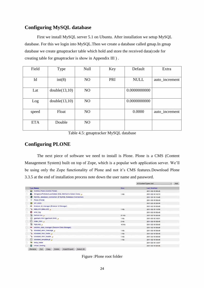
Configuring MySQL database
First we install MySQL server 5.1 on Ubuntu. After installation we setup MySQL
database. For this we login into MySQL.Then we create a database called gmap.In gmap
database we create gmaptracker table which hold and store the received data(code for
creating table for gmaptracker is show in Appendix III ) .
Field Type Null Key Default Extra
Id int(8) NO PRI NULL auto_increment
Lat double(13,10) NO 0.0000000000
Log double(13,10) NO 0.0000000000
speed Float NO 0.0000 auto_increment
ETA Double NO
Table 4.5: gmaptracker MySQL database
Configuring PLONE
The next piece of software we need to install is Plone. Plone is a CMS (Content
Management System) built on top of Zope, which is a popular web application server. We‟ll
be using only the Zope functionality of Plone and not it‟s CMS features.Download Plone
3.3.5 at the end of installation process note down the user name and password.
Figure :Plone root folder

25
Chapter 5
Result and Discussion
26
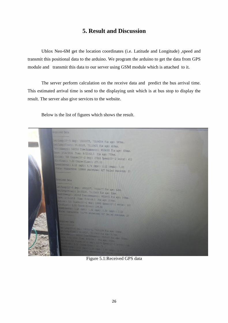
5. Result and Discussion
Ublox Neo-6M get the location coordinates (i.e. Latitude and Longitude) ,speed and
transmit this positional data to the arduino. We program the arduino to get the data from GPS
module and transmit this data to our server using GSM module which is attached to it.
The server perform calculation on the receive data and predict the bus arrival time.
This estimated arrival time is send to the displaying unit which is at bus stop to display the
result. The server also give services to the website.
Below is the list of figures which shows the result.
Figure 5.1:Received GPS data
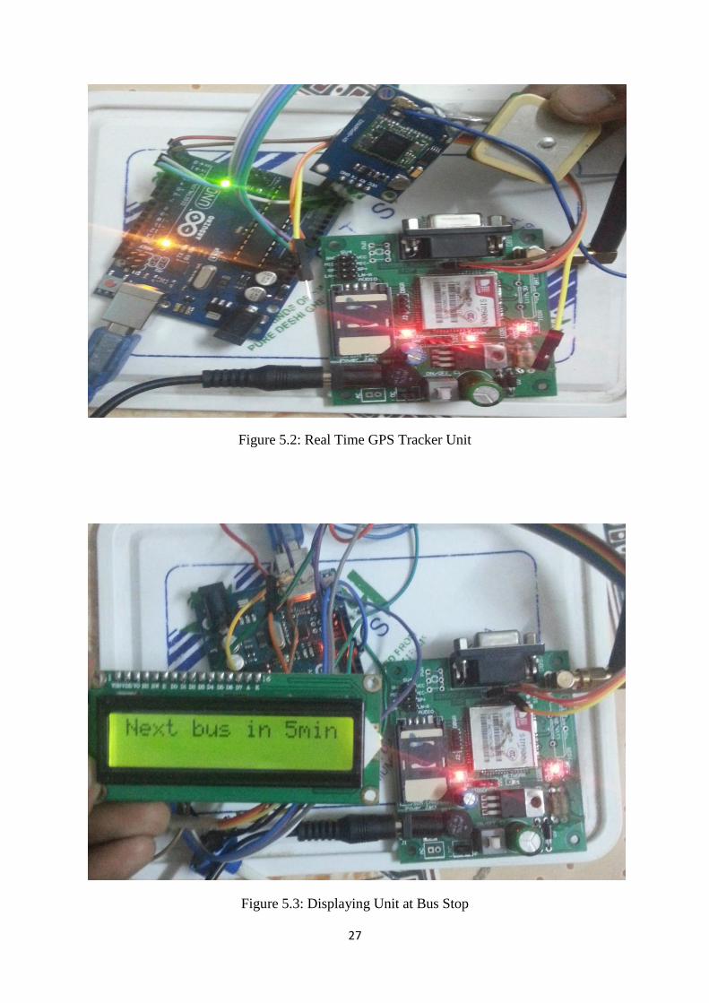
27
Figure 5.2: Real Time GPS Tracker Unit
Figure 5.3: Displaying Unit at Bus Stop

28
Chapter 6
Conclusion and Future Scope
29
6. Conclusion and Future Scope
6.1 Conclusion
Accurate prediction of bus arrival time can not only help passengers time their
departure times from work places and homes and make successful transfers by reducing
waiting times at stops, but also help transit agencies manage and operate their systems in a
more responsive manner such as real-time dispatching and scheduling. The system is capable
of tracking a large number of buses simultaneously, detecting their service routes and
directions automatically, and predicting their arrival time.
6.2 Future Scope
After analyzing the test results of the developed systems, the following issues are still
open which can be taken up as future enhancements.
Different other high sensitive GPS receiver can also be interfaced with the arduino to
get the more accurate data.
As Android phones are widely used everywhere one can built Android application for
getting the expected arrival time of bus.
Features like Emergency help can also provided in real time GPS tracker unit which
helps the driver to notify they need help.

30
Chapter 7
Reference
31
7. Reference
[1] Sudhakar K N, Rashmi , “ Predicting the Bus Arrival Time Using GPS and GSM
Technology ” Department of CSE, CMRIT, Bangalore, India , International Journal of
Science and Research (IJSR) , ISSN (Online): 2319-7064 , Volume 4 Issue 5, May 2015.
[2]Farhana Siddiqui , Abbasali Springwala , Danish Shaikh , Shumaila Siddiqui , “GPS
Based Bus Arrival Time Prediction System ” Computer Department, M.H.S.S.College of
Engineering Byculla, Mumbai, Maharashtra, India. International Journal of Engineering
Research & Technology (IJERT) , ISSN: 2278-0181 Vol. 3 Issue 2, February – 2014.
[3]Pengfei Zhou, Student Member, IEEE, Yuanqing Zheng, Student Member, IEEE, and Mo
Li, Member, IEEE “ How Long to Wait? Predicting Bus Arrival Time With Mobile Phone
Based Participatory Sensing ” IEEE TRANSACTIONS ON MOBILE COMPUTING, VOL.
13, NO. 6, JUNE 2014.
[4] Gunjal Sunil N. , Joshi Ajinkya V. , Gosavi Swapnil C , Kshirsagar Vyanktesh B. “
Dynamic Bus 5 Timetable Using GPS ”, International Journal of Advanced Research in
Computer Engineering & Technology (IJARCET) ISSN: 2278– 1323, Volume 3 ,Issue 3,
March 2014.
[5] Jerzy Letkowski, “Doing database design with MYSQL” Department of Computer,
Western New England University, Journal of Technology Research , Volume-6, December
2014
32
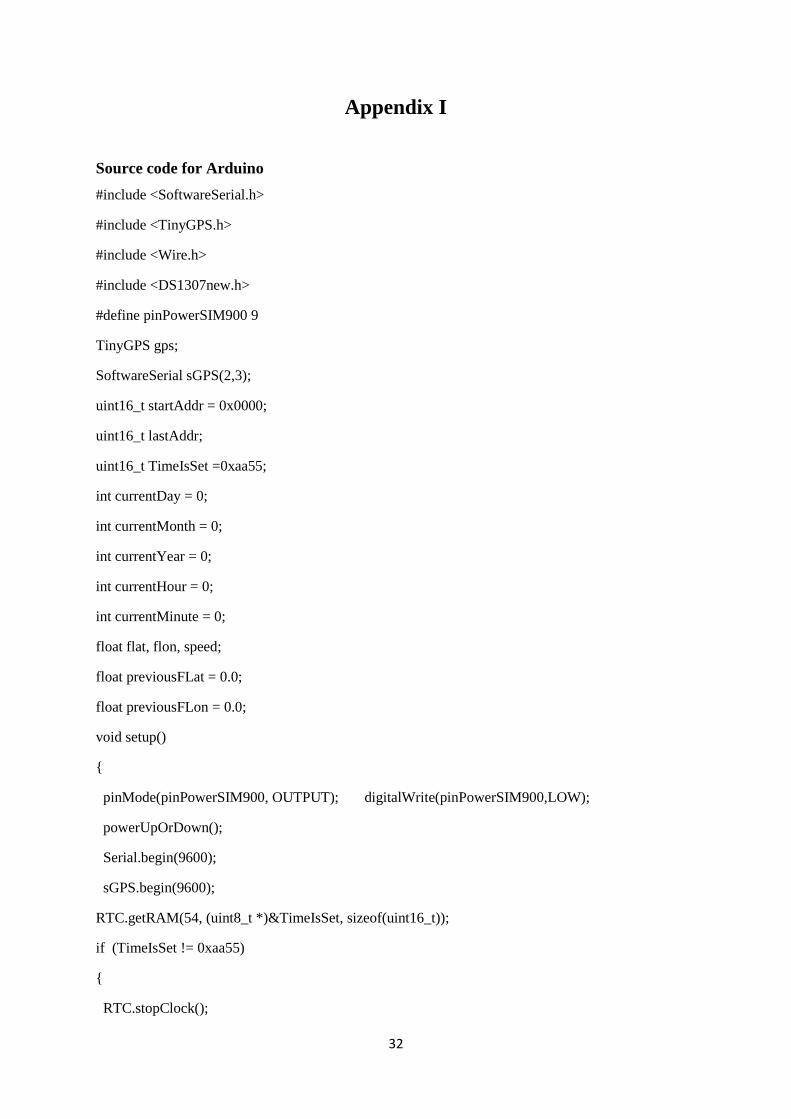
Appendix I
Source code for Arduino
#include <SoftwareSerial.h>
#include <TinyGPS.h>
#include <Wire.h>
#include <DS1307new.h>
#define pinPowerSIM900 9
TinyGPS gps;
SoftwareSerial sGPS(2,3);
uint16_t startAddr = 0x0000;
uint16_t lastAddr;
uint16_t TimeIsSet =0xaa55;
int currentDay = 0;
int currentMonth = 0;
int currentYear = 0;
int currentHour = 0;
int currentMinute = 0;
float flat, flon, speed;
float previousFLat = 0.0;
float previousFLon = 0.0;
void setup()
pinMode(pinPowerSIM900, OUTPUT); digitalWrite(pinPowerSIM900,LOW);
powerUpOrDown();
Serial.begin(9600);
sGPS.begin(9600);
RTC.getRAM(54, (uint8_t *)&TimeIsSet, sizeof(uint16_t));
if (TimeIsSet != 0xaa55)
RTC.stopClock();
33
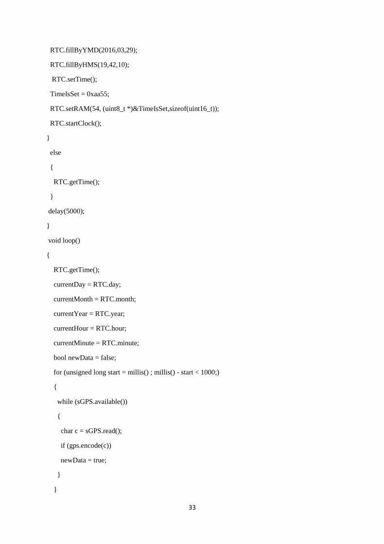
RTC.fillByYMD(2016,03,29);
RTC.fillByHMS(19,42,10);
RTC.setTime();
TimeIsSet = 0xaa55;
RTC.setRAM(54, (uint8_t *)&TimeIsSet,sizeof(uint16_t));
RTC.startClock();
else
RTC.getTime();
delay(5000);
void loop()
RTC.getTime();
currentDay = RTC.day;
currentMonth = RTC.month;
currentYear = RTC.year;
currentHour = RTC.hour;
currentMinute = RTC.minute;
bool newData = false;
for (unsigned long start = millis() ; millis() - start < 1000;)
while (sGPS.available())
char c = sGPS.read();
if (gps.encode(c))
newData = true;
34
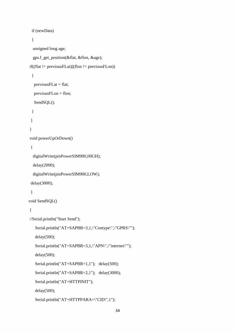
if (newData)
unsigned long age;
gps.f_get_position(&flat, &flon, &age);
if((flat != previousFLat)||(flon != previousFLon))
previousFLat = flat;
previousFLon = flon;
SendSQL();
void powerUpOrDown()
digitalWrite(pinPowerSIM900,HIGH);
delay(2000);
digitalWrite(pinPowerSIM900,LOW);
delay(3000);
void SendSQL()
//Serial.println("Start Send");
Serial.println("AT+SAPBR=3,1,\"Contype\",\"GPRS\"");
delay(500);
Serial.println("AT+SAPBR=3,1,\"APN\",\"internet\"");
delay(500);
Serial.println("AT+SAPBR=1,1"); delay(500);
Serial.println("AT+SAPBR=2,1"); delay(3000);
Serial.println("AT+HTTPINIT");
delay(500);
Serial.println("AT+HTTPPARA=\"CID\",1");
35
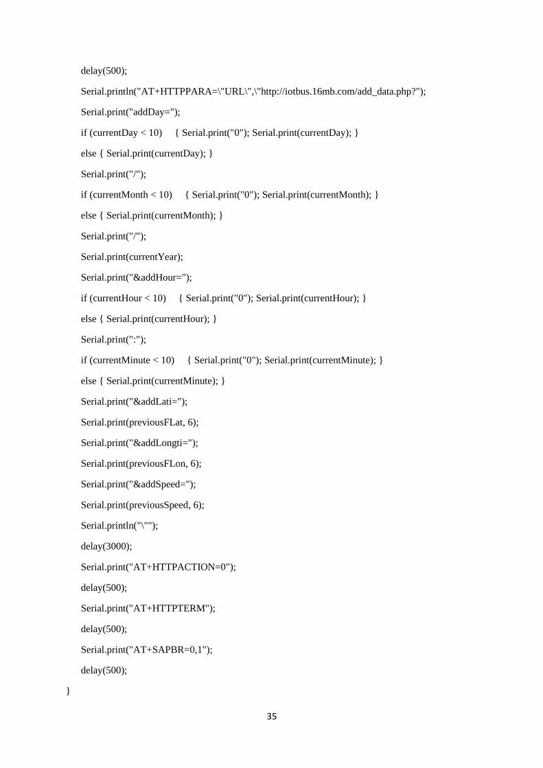
delay(500);
Serial.println("AT+HTTPPARA=\"URL\",\"http://iotbus.16mb.com/add_data.php?");
Serial.print("addDay=");
if (currentDay < 10) Serial.print("0"); Serial.print(currentDay);
else Serial.print(currentDay);
Serial.print("/");
if (currentMonth < 10) Serial.print("0"); Serial.print(currentMonth);
else Serial.print(currentMonth);
Serial.print("/");
Serial.print(currentYear);
Serial.print("&addHour=");
if (currentHour < 10) Serial.print("0"); Serial.print(currentHour);
else Serial.print(currentHour);
Serial.print(":");
if (currentMinute < 10) Serial.print("0"); Serial.print(currentMinute);
else Serial.print(currentMinute);
Serial.print("&addLati=");
Serial.print(previousFLat, 6);
Serial.print("&addLongti=");
Serial.print(previousFLon, 6);
Serial.print("&addSpeed=");
Serial.print(previousSpeed, 6);
Serial.println("\"");
delay(3000);
Serial.print("AT+HTTPACTION=0");
delay(500);
Serial.print("AT+HTTPTERM");
delay(500);
Serial.print("AT+SAPBR=0,1");
delay(500);
36
Appendix II
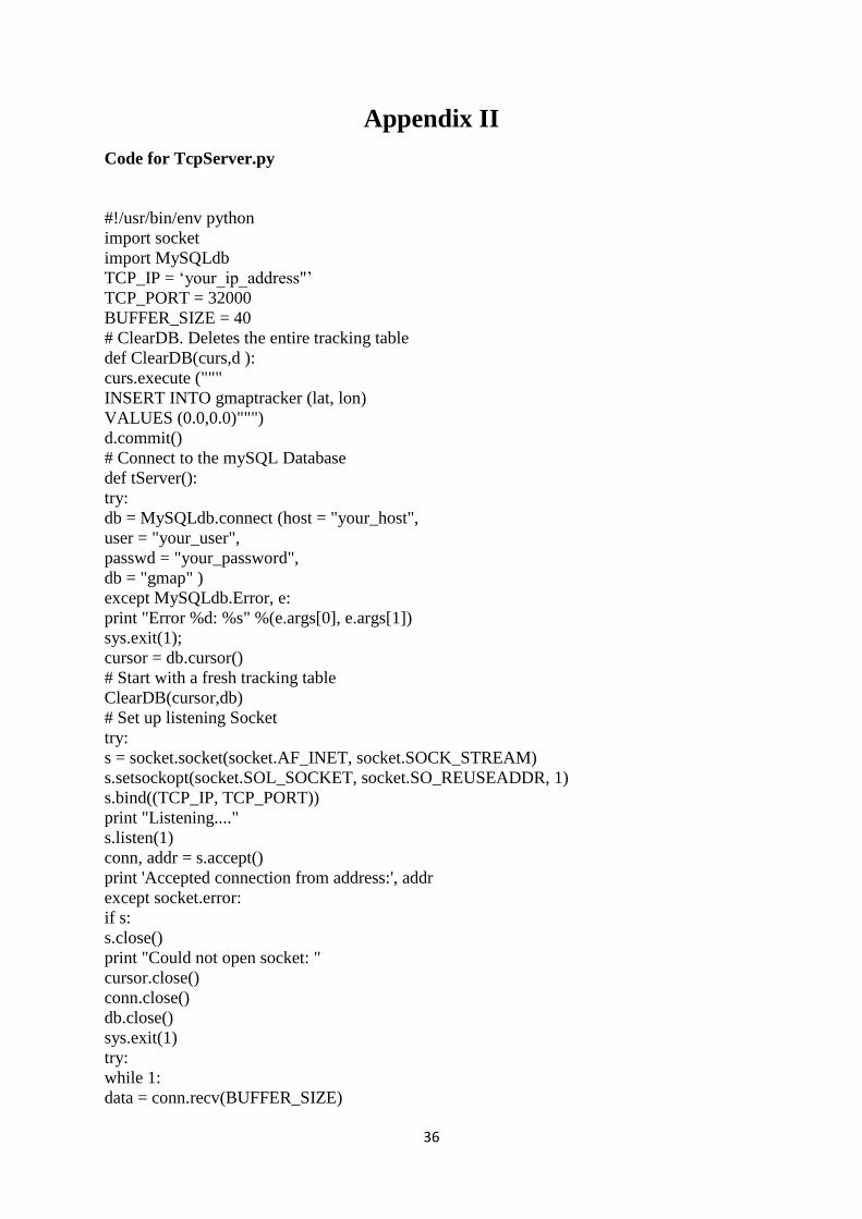
Code for TcpServer.py
#!/usr/bin/env python
import socket
import MySQLdb
TCP_IP = „your_ip_address"‟
TCP_PORT = 32000
BUFFER_SIZE = 40
# ClearDB. Deletes the entire tracking table
def ClearDB(curs,d ):
curs.execute ("""
INSERT INTO gmaptracker (lat, lon)
VALUES (0.0,0.0)""")
d.commit()
# Connect to the mySQL Database
def tServer():
try:
db = MySQLdb.connect (host = "your_host",
user = "your_user",
passwd = "your_password",
db = "gmap" )
except MySQLdb.Error, e:
print "Error %d: %s" %(e.args[0], e.args[1])
sys.exit(1);
cursor = db.cursor()
# Start with a fresh tracking table
ClearDB(cursor,db)
# Set up listening Socket
try:
s = socket.socket(socket.AF_INET, socket.SOCK_STREAM)
s.setsockopt(socket.SOL_SOCKET, socket.SO_REUSEADDR, 1)
s.bind((TCP_IP, TCP_PORT))
print "Listening...."
s.listen(1)
conn, addr = s.accept()
print 'Accepted connection from address:', addr
except socket.error:
if s:
s.close()
print "Could not open socket: "
cursor.close()
conn.close()
db.close()
sys.exit(1)
try:
while 1:
data = conn.recv(BUFFER_SIZE)
37
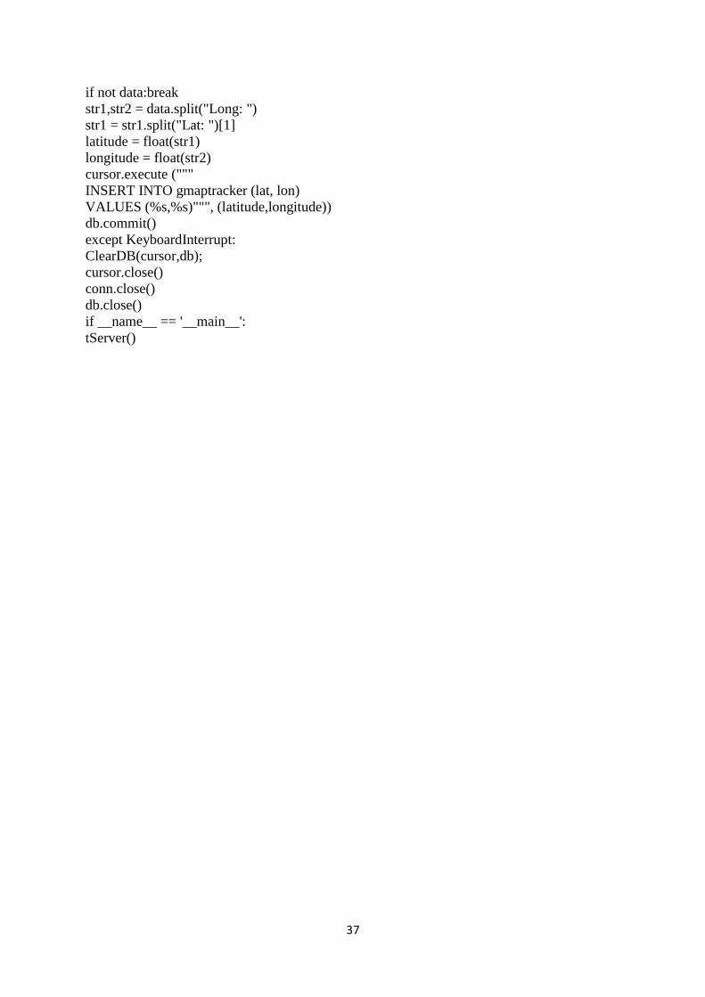
if not data:break
str1,str2 = data.split("Long: ")
str1 = str1.split("Lat: ")[1]
latitude = float(str1)
longitude = float(str2)
cursor.execute ("""
INSERT INTO gmaptracker (lat, lon)
VALUES (%s,%s)""", (latitude,longitude))
db.commit()
except KeyboardInterrupt:
ClearDB(cursor,db);
cursor.close()
conn.close()
db.close()
if __name__ == '__main__':
tServer()
38
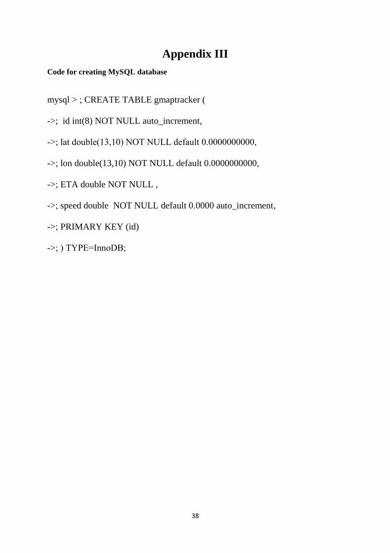
Appendix III
Code for creating MySQL database
mysql > ; CREATE TABLE gmaptracker (
->; id int(8) NOT NULL auto_increment,
->; lat double(13,10) NOT NULL default 0.0000000000,
->; lon double(13,10) NOT NULL default 0.0000000000,
->; ETA double NOT NULL ,
->; speed double NOT NULL default 0.0000 auto_increment,
->; PRIMARY KEY (id)
->; ) TYPE=InnoDB;
39
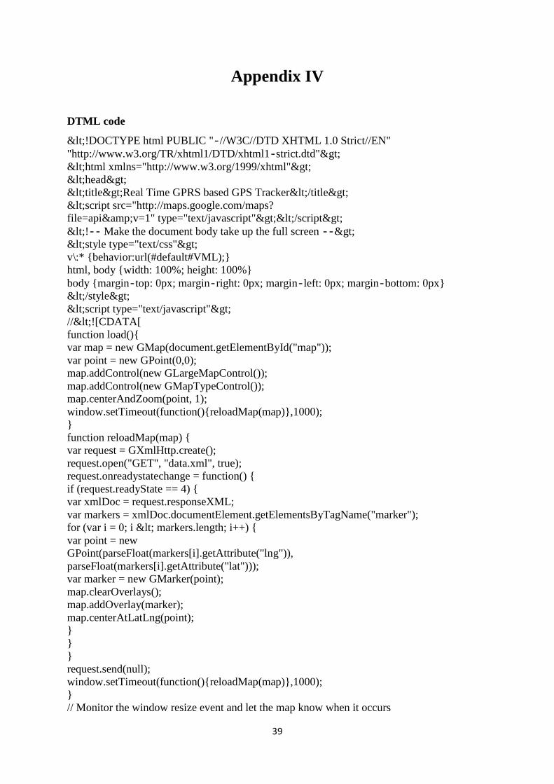
Appendix IV
DTML code
<!DOCTYPE html PUBLIC "‐//W3C//DTD XHTML 1.0 Strict//EN"
"http://www.w3.org/TR/xhtml1/DTD/xhtml1‐strict.dtd">
<html xmlns="http://www.w3.org/1999/xhtml">
<head>
<title>Real Time GPRS based GPS Tracker</title>
<script src="http://maps.google.com/maps?
file=api&v=1" type="text/javascript"></script>
<!‐‐ Make the document body take up the full screen ‐‐>
<style type="text/css">
v\:* behavior:url(#default#VML);
html, body width: 100%; height: 100%
body margin‐top: 0px; margin‐right: 0px; margin‐left: 0px; margin‐bottom: 0px
</style>
<script type="text/javascript">
//<![CDATA[
function load()
var map = new GMap(document.getElementById("map"));
var point = new GPoint(0,0);
map.addControl(new GLargeMapControl());
map.addControl(new GMapTypeControl());
map.centerAndZoom(point, 1);
window.setTimeout(function()reloadMap(map),1000);
function reloadMap(map)
var request = GXmlHttp.create();
request.open("GET", "data.xml", true);
request.onreadystatechange = function()
if (request.readyState == 4)
var xmlDoc = request.responseXML;
var markers = xmlDoc.documentElement.getElementsByTagName("marker");
for (var i = 0; i < markers.length; i++)
var point = new
GPoint(parseFloat(markers[i].getAttribute("lng")),
parseFloat(markers[i].getAttribute("lat")));
var marker = new GMarker(point);
map.clearOverlays();
map.addOverlay(marker);
map.centerAtLatLng(point);
request.send(null);
window.setTimeout(function()reloadMap(map),1000);
// Monitor the window resize event and let the map know when it occurs
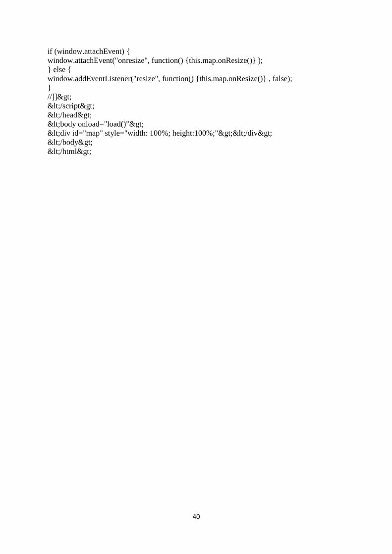
40
if (window.attachEvent)
window.attachEvent("onresize", function() this.map.onResize() );
else
window.addEventListener("resize", function() this.map.onResize() , false);
//]]>
</script>
</head>
<body onload="load()">
<div id="map" style="width: 100%; height:100%;"></div>
</body>
</html>