Embed Size (px)
Citation preview
PREDICTION AND INVESTIGATION OF SURFACE ROUGHNESS WHILE TURNING SGIRON WITH CUBIC BORON NITRIDE (CBN) AND TUNGSTEN CARBIDE INSERTS
K.M. Kumar1,2 and P. Hariharan21St. Joseph’s College of Engineering, Sholinganallur, Chennai, Tamilnadu, India
2College of Engineering, Anna University, Chennai, Tamilnadu, IndiaE-mail: [email protected]
Received May 2016, Accepted August 2016No. 16-CSME-79, E.I.C. Accession 3965
ABSTRACTThis work compares the effect of cubic boron nitride (CBN) and multilayer (TiCN+Al2O3+TiN) coatedtungsten carbide (WC) tools during the turning of spheroidal graphite (SG) nodular iron. Nodular ironshave more ductility which is required in mechanical components that demand high fatigue resistance likecrankshafts, cam shafts, bearing caps and clutch housings. The impact of various process parameters likethe depth of cut, cutting speed and feed on the surface roughness (Ra) of SG iron is studied and optimizedusing the response surface model. The chip morphology is also discussed for evaluation of the qualityof the turned surface. The experimental outcomes reveal that the WC tool offers a high surface finish atthe optimal combination of the cutting speed at 102 meter/minute, feed at 0.051 millimeter/revolution anddepth of cut at 0.5 millimeter and that, for the CBN insert, at 245 meter/minute of cutting speed, 0.051millimeter/revolution of feed and 0.75 millimeter of depth of cut.
Keywords: roughness, machining, RSM, morphology, CBN, multilayer, ductile iron.
PRÉDICTION ET INVESTIGATION DE LA RUGOSITÉ DE LA SURFACE PENDANT LETOURNAGE DE FONTE SG AVEC NITRURE DE BORE CUBIQUE ET INSERTION DE
CARBURE DE TUNGSTÈNE
RÉSUMÉLe travail de recherche présent porte sur un procédé de conception innovateur d’un moteur électrique rotatifà mécanisme d’engrenage et aimant permanent intégré. Un moteur courant continu à commutation et unsystème mécanique à engrenage planétaire sont utilisés comme exemple. En se basant sur les exigences etcontraintes de conception, un concept détaillé du rotor et du stator est obtenu. Une méthode de circuit ma-gnétique équivalent à 1-D est appliquée pour analyser la performance du dispositif intégré, et il est vérifiépar le logiciel FEM. Les méthodes de conception pour les trains d’engrenage, les profils, le nombre de dents,et la puissance de l’engrenage sont aussi introduites. Finalement nous obtenons un dispositif intégré réali-sable qui réduit le couple d’encochage et l’ondulation du couple de 92.02% et de 50.14% respectivement,tandis que la densité de couple est augmentée de 16.66%.
Mots-clés : moteur électrique rotatif à mécanisme d’engrenage et aimant intégré; conception du moteur;procédé de conception intégré; mécanisme d’engrenage.
Transactions of the Canadian Society for Mechanical Engineering, Vol. 41, No. 1, 2017 129
1. INTRODUCTION
Ductile irons like nodular ductile iron/spheroidal graphite (SG) iron, compacted graphite iron and temperedductile iron are currently used in automotive, energy, wind power industries and construction of machines[1, 2]. Nodular iron is utilized as a part of wheels, crankshafts, and camshafts. Added substances including,for example, molybdenum (Mb), magnesium (Mg), copper (Cu), silicon (Si) and chromium (Cr) can be usedfor enhancing the mechanical properties of SG cast iron. But the addition of these additives results in poormachinability for SG iron [3]. The percentages of machinability are comparable to high strength steel alloys,like AISI 1110 steel and AISI 4140 steels [4]. The SG iron structure with graphite content is represented astiny round spheroidal shapes in its matrix [5]. A small quantity of Mg, when injected into ductile iron, existsin round shapes that give prevalent flexibility and high quality and durability. Increasing either hardnessor ductility reduces machinability. The most exciting challenges to metallurgists are to elevate the qualityof materials with a minimum increase in cost, which has been accomplished by alloying, cold working,utilization of phase alterations, and the modification of grain dimension and microstructure. Accordingly,the need for machining has turned out to be more upon material microstructures.
Ductile iron is effortless to machine. However, it generates BUE on the tool due to its higher ferritecontent. Certain grates of SG iron machining result in quick wear due to pearlite substance. During themachining of ductile cast iron, the graphite particles decide the cutting forces and surface irregularities [5,6]. For machining SG iron, it is useful to get some reasonable cutting parameter values from the machininghandbook [7–9]. The machinability of ductile cast irons depends on their microstructure, alloy content,hardness, and ductility.
Nowadays, different types of coated carbide tools are used for machining hardened materials like SG iron,austempered ductile iron, high strength steel alloys etc., The main coating materials like TiC, Al2O3, TiNand TiCN coatings improve the cutting tool wear resistance and maintain the toughness of cemented carbide[10, 11]. Most of the multilayer CVD coated carbide tools like TiCN+Al2O3+TiN are used for machiningaustempered ductile iron [12, 13]. SiN tools perform poorly when used for machining ductile iron. Coatedtools show superior performance. Tungsten carbide substrates with a coating of TiCN/Al2O3/TiN are usedin the early period for machining SG iron. The coating of TiCN diminishes and the impact of the Al2O3becomes overwhelming at higher speeds. It is evident that the use of the latest multi-layered carbide tool de-creases the flank wear by 40% at 200 meter/minute speeds in comparison with conservative coated carbide.Also, the latest grades likewise accomplish a 25% enhancement in tool life at 300 meter/minute [14].
Either a ceramic/CBN tool or a coated tool is used for dry machining to face the extraordinary heatproduced by the operation. Low thermal conductivity and low friction coefficient coatings are excellent atseparating a tool from heat. TiAlN coatings are greatly suggested for dry machining of cast ferrous materials,including cast irons [14].
The primary purpose of this experimental study is to compare the cutting operation of the two differentcutting tools (CBN and coated WC tools) in view of workpiece Ra and chip morphology of ductile iron. Theresults observed on the Ra of SG iron with CBN and coated WC tools are reported, along with the exami-nation results of chip morphology. A limited literature survey has been reported in ductile iron machiningwith CBN and coated WC tools. Since there is an absence of any related work carried out on the machiningof ductile iron with CBN tool, an effort has been made to determine the optimum machining parameters.
2. MATERIALS AND METHODS
2.1. Materials, Experimental Set-up and MeasurementThe material used in the turning experiments was a ductile cast iron (SG iron). The work material composi-tion is shown in Table 1. The work materials were mixed with additives like molybdenum (Mb) and Nickel(Ni) for enhancing the mechanical properties of the SG iron apart from the ordinary chemical composition
130 Transactions of the Canadian Society for Mechanical Engineering, Vol. 41, No. 1, 2017
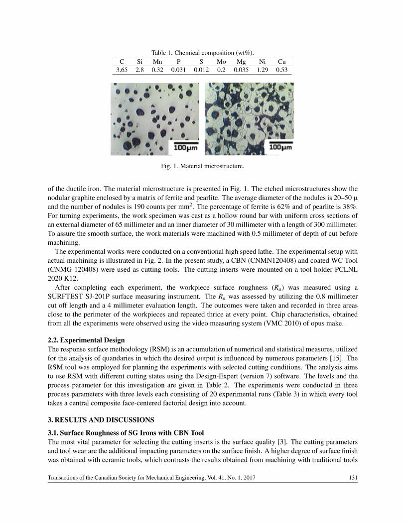
Table 1. Chemical composition (wt%).C Si Mn P S Mo Mg Ni Cu
3.65 2.8 0.32 0.031 0.012 0.2 0.035 1.29 0.53
Fig. 1. Material microstructure.
of the ductile iron. The material microstructure is presented in Fig. 1. The etched microstructures show thenodular graphite enclosed by a matrix of ferrite and pearlite. The average diameter of the nodules is 20–50 µ
and the number of nodules is 190 counts per mm2. The percentage of ferrite is 62% and of pearlite is 38%.For turning experiments, the work specimen was cast as a hollow round bar with uniform cross sections ofan external diameter of 65 millimeter and an inner diameter of 30 millimeter with a length of 300 millimeter.To assure the smooth surface, the work materials were machined with 0.5 millimeter of depth of cut beforemachining.
The experimental works were conducted on a conventional high speed lathe. The experimental setup withactual machining is illustrated in Fig. 2. In the present study, a CBN (CNMN120408) and coated WC Tool(CNMG 120408) were used as cutting tools. The cutting inserts were mounted on a tool holder PCLNL2020 K12.
After completing each experiment, the workpiece surface roughness (Ra) was measured using aSURFTEST SJ-201P surface measuring instrument. The Ra was assessed by utilizing the 0.8 millimetercut off length and a 4 millimeter evaluation length. The outcomes were taken and recorded in three areasclose to the perimeter of the workpieces and repeated thrice at every point. Chip characteristics, obtainedfrom all the experiments were observed using the video measuring system (VMC 2010) of opus make.
2.2. Experimental DesignThe response surface methodology (RSM) is an accumulation of numerical and statistical measures, utilizedfor the analysis of quandaries in which the desired output is influenced by numerous parameters [15]. TheRSM tool was employed for planning the experiments with selected cutting conditions. The analysis aimsto use RSM with different cutting states using the Design-Expert (version 7) software. The levels and theprocess parameter for this investigation are given in Table 2. The experiments were conducted in threeprocess parameters with three levels each consisting of 20 experimental runs (Table 3) in which every tooltakes a central composite face-centered factorial design into account.
3. RESULTS AND DISCUSSIONS
3.1. Surface Roughness of SG Irons with CBN ToolThe most vital parameter for selecting the cutting inserts is the surface quality [3]. The cutting parametersand tool wear are the additional impacting parameters on the surface finish. A higher degree of surface finishwas obtained with ceramic tools, which contrasts the results obtained from machining with traditional tools
Transactions of the Canadian Society for Mechanical Engineering, Vol. 41, No. 1, 2017 131
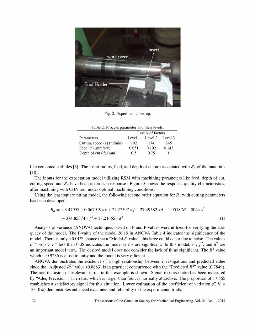
Fig. 2. Experimental set-up.
Table 2. Process parameter and their levels.Levels of factors
Parameters Level 1 Level 2 Level 3Cutting speed (v) (m/min) 102 174 245Feed ( f ) (mm/rev) 0.051 0.102 0.143Depth of cut (d) (mm) 0.5 0.75 1
like cemented carbides [3]. The insert radius, feed, and depth of cut are associated with Ra of the materials[10].
The inputs for the expectation model utilizing RSM with machining parameters like feed, depth of cut,cutting speed and Ra have been taken as a response. Figure 5 shows the response quality characteristics,after machining with CBN tool under optimal machining conditions.
Using the least square fitting model, the following second order equation for Ra with cutting parametershas been developed.
Ra = +3.47957+0.067919∗ v+71.27597∗ f −27.49582∗d −1.95187E −004∗ s2
−374.85374∗ f 2 +18.21455∗d2 (1)
Analysis of variance (ANOVA) techniques based on F and P-values were utilized for verifying the ade-quacy of the model. The F-value of the model 26.19 in ANOVA Table 4 indicates the significance of themodel. There is only a 0.01% chance that a “Model F-value” this large could occur due to noise. The valuesof “prop > F” less than 0.05 indicates the model terms are significant. In this model, v2, f 2, and d2 arean important model term. The desired model does not consider the lack of fit as significant. The R2 valuewhich is 0.9236 is close to unity and the model is very efficient.
ANOVA demonstrates the existence of a high relationship between investigations and predicted valuesince the “Adjusted R2” value (0.8883) is in practical concurrence with the “Predicted R2” value (0.7849).The non-inclusion of irrelevant terms in this example is shown. Signal to noise ratio has been measuredby “Adeq Precision”. The ratio, which is larger than four, is normally attractive. The proportion of 17.565establishes a satisfactory signal for this situation. Lower estimation of the coefficient of variation (C.V. =10.10%) demonstrates enhanced exactness and reliability of the experimental trials.
132 Transactions of the Canadian Society for Mechanical Engineering, Vol. 41, No. 1, 2017
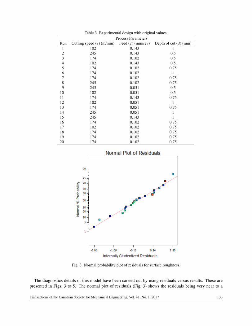
Table 3. Experimental design with original values.Process Parameters
Run Cutting speed (v) (m/min) Feed ( f ) (mm/rev) Depth of cut (d) (mm)1 102 0.143 12 245 0.143 0.53 174 0.102 0.54 102 0.143 0.55 174 0.102 0.756 174 0.102 17 174 0.102 0.758 245 0.102 0.759 245 0.051 0.5
10 102 0.051 0.511 174 0.143 0.7512 102 0.051 113 174 0.051 0.7514 245 0.051 115 245 0.143 116 174 0.102 0.7517 102 0.102 0.7518 174 0.102 0.7519 174 0.102 0.7520 174 0.102 0.75
Fig. 3. Normal probability plot of residuals for surface roughness.
The diagnostics details of this model have been carried out by using residuals versus results. These arepresented in Figs. 3 to 5. The normal plot of residuals (Fig. 3) shows the residuals being very near to a
Transactions of the Canadian Society for Mechanical Engineering, Vol. 41, No. 1, 2017 133
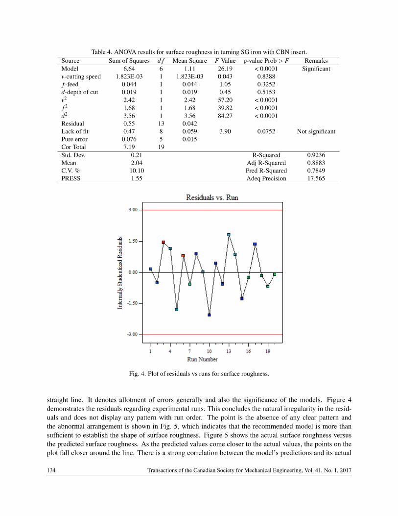
Table 4. ANOVA results for surface roughness in turning SG iron with CBN insert.Source Sum of Squares d f Mean Square F Value p-value Prob > F RemarksModel 6.64 6 1.11 26.19 < 0.0001 Significantv-cutting speed 1.823E-03 1 1.823E-03 0.043 0.8388f -feed 0.044 1 0.044 1.05 0.3252d-depth of cut 0.019 1 0.019 0.45 0.5153v2 2.42 1 2.42 57.20 < 0.0001f 2 1.68 1 1.68 39.82 < 0.0001d2 3.56 1 3.56 84.27 < 0.0001Residual 0.55 13 0.042Lack of fit 0.47 8 0.059 3.90 0.0752 Not significantPure error 0.076 5 0.015Cor Total 7.19 19Std. Dev. 0.21 R-Squared 0.9236Mean 2.04 Adj R-Squared 0.8883C.V. % 10.10 Pred R-Squared 0.7849PRESS 1.55 Adeq Precision 17.565
Fig. 4. Plot of residuals vs runs for surface roughness.
straight line. It denotes allotment of errors generally and also the significance of the models. Figure 4demonstrates the residuals regarding experimental runs. This concludes the natural irregularity in the resid-uals and does not display any pattern with run order. The point is the absence of any clear pattern andthe abnormal arrangement is shown in Fig. 5, which indicates that the recommended model is more thansufficient to establish the shape of surface roughness. Figure 5 shows the actual surface roughness versusthe predicted surface roughness. As the predicted values come closer to the actual values, the points on theplot fall closer around the line. There is a strong correlation between the model’s predictions and its actual
134 Transactions of the Canadian Society for Mechanical Engineering, Vol. 41, No. 1, 2017
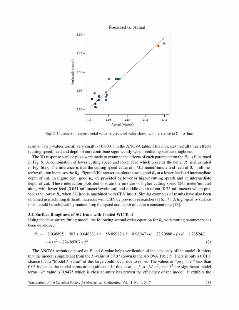
Fig. 5. Closeness of experimental value vs predicted value shown with reference to Y = X line.
results. The p-values are all very small (< 0.0001) in the ANOVA table. This indicates that all three effects(cutting speed, feed and depth of cut) contribute significantly when predicting surface roughness.
The 3D response surface plots were made to examine the effects of each parameter on the Ra as illustratedin Fig. 6. A combination of lower cutting speed and lower feed which presents the better Ra is illustratedin Fig. 6(a). The inference is that the cutting speed value of 173.5 meter/minute and feed of 0.1 millime-ter/revolution increases the Ra. Figure 6(b) interaction plots show a good Ra at a lower feed and intermediatedepth of cut. In Figure 6(c), good Ra are provided by lower or higher cutting speeds and an intermediatedepth of cut. These interaction plots demonstrate the mixture of higher cutting speed (245 meter/minute)along with lower feed (0.051 millimeter/revolution) and middle depth of cut (0.75 millimeter) which pro-vides the lowest Ra when SG iron is machined with CBN insert. Similar examples of results have also beenobtained in machining difficult materials with CBN by previous researchers [16, 17]. A high-quality surfacefinish could be achieved by maintaining the speed and depth of cut at a constant rate [18].
3.2. Surface Roughness of SG Irons with Coated WC ToolUsing the least square fitting model, the following second order equation for Ra with cutting parameters hasbeen developed.
Ra = −8.03689E −003+0.046331∗ v−58.89972∗ f −0.98047∗d +22.20886∗ f ∗d −1.23524E
−4∗ v2 +274.89707∗ f 2 (2)
The ANOVA technique based on F and P-value helps verification of the adequacy of the model. It infersthat the model is significant from the F-value of 39.07 shown in the ANOVA Table 5. There is only a 0.01%chance that a “Model F-value” of this large could occur due to noise. The values of “prop > F” less than0.05 indicates the model terms are significant. In this case, v, f , d, f d, v2, and f 2 are significant modelterms. R2 value is 0.9475 which is close to unity has proven the efficiency of the model. It exhibits the
Transactions of the Canadian Society for Mechanical Engineering, Vol. 41, No. 1, 2017 135
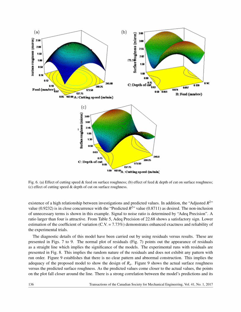
Fig. 6. (a) Effect of cutting speed & feed on surface roughness; (b) effect of feed & depth of cut on surface roughness;(c) effect of cutting speed & depth of cut on surface roughness.
existence of a high relationship between investigations and predicted values. In addition, the “Adjusted R2”value (0.9232) is in close concurrence with the “Predicted R2” value (0.8711) as desired. The non-inclusionof unnecessary terms is shown in this example. Signal to noise ratio is determined by “Adeq Precision”. Aratio larger than four is attractive. From Table 5, Adeq Precision of 22.68 shows a satisfactory sign. Lowerestimation of the coefficient of variation (C.V. = 7.73%) demonstrates enhanced exactness and reliability ofthe experimental trials.
The diagnostic details of this model have been carried out by using residuals versus results. These arepresented in Figs. 7 to 9. The normal plot of residuals (Fig. 7) points out the appearance of residualsas a straight line which implies the significance of the models. The experimental runs with residuals arepresented in Fig. 8. This implies the random nature of the residuals and does not exhibit any pattern withrun order. Figure 9 establishes that there is no clear pattern and abnormal construction. This implies theadequacy of the proposed model to show the design of Ra. Figure 9 shows the actual surface roughnessversus the predicted surface roughness. As the predicted values come closer to the actual values, the pointson the plot fall closer around the line. There is a strong correlation between the model’s predictions and its
136 Transactions of the Canadian Society for Mechanical Engineering, Vol. 41, No. 1, 2017
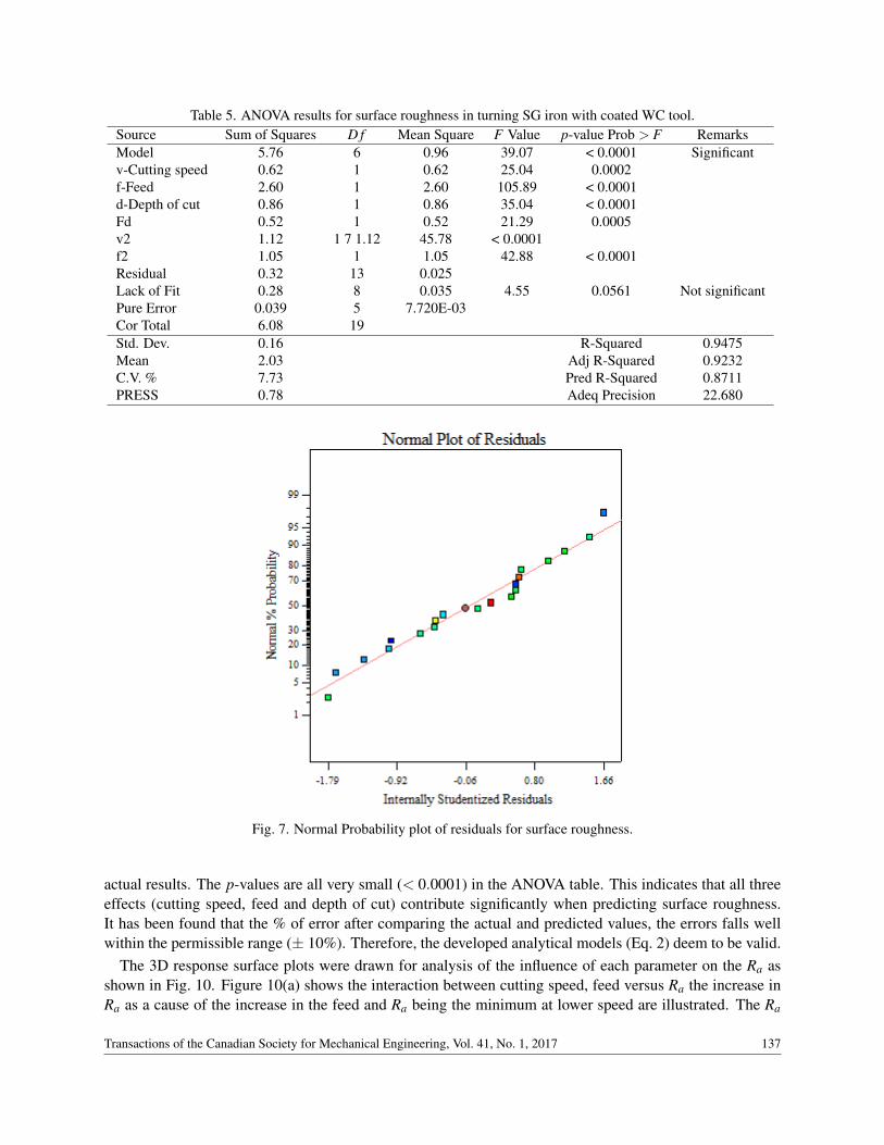
Table 5. ANOVA results for surface roughness in turning SG iron with coated WC tool.Source Sum of Squares D f Mean Square F Value p-value Prob > F RemarksModel 5.76 6 0.96 39.07 < 0.0001 Significantv-Cutting speed 0.62 1 0.62 25.04 0.0002f-Feed 2.60 1 2.60 105.89 < 0.0001d-Depth of cut 0.86 1 0.86 35.04 < 0.0001Fd 0.52 1 0.52 21.29 0.0005v2 1.12 1 7 1.12 45.78 < 0.0001f2 1.05 1 1.05 42.88 < 0.0001Residual 0.32 13 0.025Lack of Fit 0.28 8 0.035 4.55 0.0561 Not significantPure Error 0.039 5 7.720E-03Cor Total 6.08 19Std. Dev. 0.16 R-Squared 0.9475Mean 2.03 Adj R-Squared 0.9232C.V. % 7.73 Pred R-Squared 0.8711PRESS 0.78 Adeq Precision 22.680
Fig. 7. Normal Probability plot of residuals for surface roughness.
actual results. The p-values are all very small (< 0.0001) in the ANOVA table. This indicates that all threeeffects (cutting speed, feed and depth of cut) contribute significantly when predicting surface roughness.It has been found that the % of error after comparing the actual and predicted values, the errors falls wellwithin the permissible range (± 10%). Therefore, the developed analytical models (Eq. 2) deem to be valid.
The 3D response surface plots were drawn for analysis of the influence of each parameter on the Ra asshown in Fig. 10. Figure 10(a) shows the interaction between cutting speed, feed versus Ra the increase inRa as a cause of the increase in the feed and Ra being the minimum at lower speed are illustrated. The Ra
Transactions of the Canadian Society for Mechanical Engineering, Vol. 41, No. 1, 2017 137
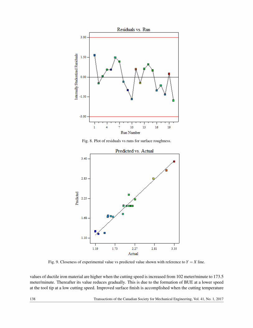
Fig. 8. Plot of residuals vs runs for surface roughness.
Fig. 9. Closeness of experimental value vs predicted value shown with reference to Y = X line.
values of ductile iron material are higher when the cutting speed is increased from 102 meter/minute to 173.5meter/minute. Thereafter its value reduces gradually. This is due to the formation of BUE at a lower speedat the tool tip at a low cutting speed. Improved surface finish is accomplished when the cutting temperature
138 Transactions of the Canadian Society for Mechanical Engineering, Vol. 41, No. 1, 2017

Fig. 10. (a) Effect of cutting speed & feed on surface roughness; (b) effect of feed & depth of cut on surface roughness;(c) effect of cutting speed & depth of cut on surface roughness.
raises and reduces build-up edge on the tip of the tool. The same observation was also covered by previousresearchers [3, 19]. Coated tools past a certain speed of machining could be distributed to the incident ofrubbing during turning results in the fall of Ra [20]. Figure 10(b) shows poor Ra being obtained at highfeed and a total absence of any influence of depth of cut. Figure 10(c) demonstrates Ra being maximumwhen depth cut is increased and good surface finish is attained at a lower cutting speed. The changes in thefeed show higher sensitivity in Ra compared to other parameters [21]. These interaction plots demonstratethe combination of lower cutting speed (102 meter/minute) along with a lower depth of cut and lower feedwhich offer the lowest Ra of SG iron with a coated WC tool. The multilayer coated cutting tool producesthe best Ra at lower feed and higher speed [22].
Transactions of the Canadian Society for Mechanical Engineering, Vol. 41, No. 1, 2017 139
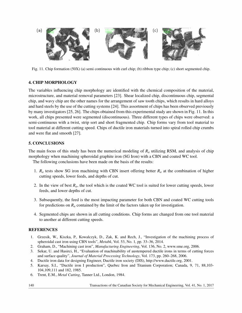
Fig. 11. Chip formation (50X) (a) semi continuous with curl chip; (b) ribbon type chip; (c) short segmented chip.
4. CHIP MORPHOLOGY
The variables influencing chip morphology are identified with the chemical composition of the material,microstructure, and material removal parameters [23]. Shear localized chip, discontinuous chip, segmentalchip, and wavy chip are the other names for the arrangement of saw tooth chips, which results in hard alloysand hard steels by the use of the cutting systems [24]. This assortment of chips has been observed previouslyby many investigators [25, 26]. The chips obtained from this experimental study are shown in Fig. 11. In thiswork, all chips presented were segmented (discontinuous). Three different types of chips were observed: asemi-continuous with a twist, strip sort and short fragmented chip. Chip forms vary from tool material totool material at different cutting speed. Chips of ductile iron materials turned into spiral rolled chip crumbsand were flat and smooth [27].
5. CONCLUSIONS
The main focus of this study has been the numerical modeling of Ra utilizing RSM, and analysis of chipmorphology when machining spheroidal graphite iron (SG Iron) with a CBN and coated WC tool.
The following conclusions have been made on the basis of the results:
1. Ra tests show SG iron machining with CBN insert offering better Ra at the combination of highercutting speeds, lower feeds, and depths of cut.
2. In the view of best Ra, the tool which is the coated WC tool is suited for lower cutting speeds, lowerfeeds, and lower depths of cut.
3. Subsequently, the feed is the most impacting parameter for both CBN and coated WC cutting toolsfor predictions on Ra contained by the limit of the factors taken up for investigation.
4. Segmented chips are shown in all cutting conditions. Chip forms are changed from one tool materialto another at different cutting speeds.
REFERENCES
1. Grzesik, W., Kiszka, P., Kowalczyk, D., Zak, K. and Rech, J., “Investigation of the machining process ofspheroidal cast iron using CBN tools”, Metabk, Vol. 53, No. 1, pp. 33–36, 2014.
2. Graham, D., “Machining cast iron”, Manufacturing Engineering, Vol. 136, No. 2, www.sme.org, 2006.3. Sekar, U. and Hasirci, H., “Evaluation of machinability of austempered ductile irons in terms of cutting forces
and surface quality”, Journal of Material Processing Technology, Vol. 173, pp. 260–268, 2006.4. Ductile iron data for designing Engineer, Ductile iron society (DIS), http://www.ductile.org, 2001.5. Karsay, S.I., “Ductile iron I production”, Quebec Iron and Titanium Corporation; Canada, 9, 71, 88,103-
104,109,111 and 182, 1985.6. Trent, E.M., Metal Cutting, Tanner Ltd., London, 1984.
140 Transactions of the Canadian Society for Mechanical Engineering, Vol. 41, No. 1, 2017
7. The Iron Casting Handbook, Iron Casting Society Inc., 1981.8. Machining Data Handbook, 3rd ed, Metcut Research associates Inc., Cincinnati, OH, 1980.9. Machining Ductile Irons, International Nickel Co. Inc., New York, 2001.
10. Cakir, M.C., Bayram, A., Isik, Y. and Salar, B., “The effect of austempering temperature and time onto themachinability of austempered ductile iron”, Materials science and Engineering A, Vol. 407, pp. 147–153, 2005.
11. Diniz, A.E., Marcondes, F.C. and Coppini, N.L., Technologia da Usinagem dos Materials, 5th ed., ArtliberEditora, Sao Paulo, 2006.
12. Grzesik, W., Rech, J., Zak, K. and Claudin, C., “Machining performance of pearlitic-ferritic nodular cast ironwith coated carbide and silicon nitride ceramic tools”, International Journal of Machine Tools & Manufacture,Vol. 49, pp. 125–133, 2009.
13. Santhanam, A.T., “Carbide’s for metal cutting”, in Kennametal Comprehensive Application Engineering Guide,Kennametal University, Latrobe, PA, Vol. 1, pp. 3–6, 2005.
14. Srivastava, A.K. and Finn, M.E., “Machining cast iron components”, Modern casting, AFS, IL, USA.http://www.afsinc.org/multimedia/contentMC.cfm?ItemNumber=11371
15. Montgomery, D.C., Design and Analysis of Experiments, John Wiley & Sons, New York, 2001.16. Chavoshi, S.Z. and Tajdari, M., “Surface roughness modelling in hard turning operation of AISI 4140 using
CBN cutting tool”, Int. J. Mater. Form., Vol. 3, No. 4, pp. 233–239, 2010.17. Auoici, H., “Analysis of surface roughness and cutting force component in hard turning with CBN tool: Predic-
tion model and cutting condition optimization”, Measurement, Vol. 45, No. 3, pp. 344–353, 2012.18. Datt, J. and Batra, U., “Influence of composition and austempering temperature on machinability of austempered
ductile iron”, International Journal of Chemical, Nuclear, Materials and Metallurgical Engineering, Vol. 7, No.2, 2013.
19. Aslantas, K. and Ucun, I., “The performance of ceramic and cermet cutting tools for machining of austemperedductile iron”, Int. J. Adv. Manuf. Technol., Vol. 41, pp. 642–650, 2009.
20. Shanmugam, S. and Krishnamurthy, R., “Machinability study on pearlitic spheroidal graphite cast iron”, Inter-national Journal of Production Research, Vol. 30, No. 1, pp. 189–197, 2007.
21. Kacal, A. and Gulesin, M., “Determination of optimal cutting conditions in finish turning of austempered ductileiron using taguchi design method”, Journal of Scientific & Industrial Research, Vol. 70, pp. 278–283, 2011.
22. Kribes, N., Hessainia, Z. and Yallese, M.A., “Optimization of machining parameters in hard turning by desirabil-ity function analysis using Response Surface Methodology”, in Proceedings of the Sixth Conference on Designand Modeling of Mechanical Systems, Hammamet, Tunisia, 2015.
23. Dubensky, W.J. and Rundman, K.B., “An electron microscope study of carbide formation in austempered ductileiron”, Trans. Am. Foundry Soc., Vol. 64, No. 85, pp. 389–394, 1985.
24. Komanduri, R. and Brown, R.H., “The mechanics of chip segmentation in machining”, ASME J. Eng. Ind., Vol.103, No. 1, pp. 33–51, 1981.
25. Pashby, I.R., Wallbank, J. and Boud, F., “Ceramic tool wear when machining austempered ductile iron”, Wear,Vol. 162–164, pp. 22–33, 1993.
26. Vasconcelos de Carvalho, M., et al., “An analysis of the machinability of ASTM grades 2 and 3 austemperedductile iron”, Journal of Materials Processing Technology, Vol. 213, pp. 560–573, 2013.
27. Guo, X. and Wan, D., “An experimental study on machinability of austempered ductile iron during dry turn-ing by ceramic cutting tools”, in Proceedings of the ASME 2012 International Design Engineering TechnicalConferences & Computer and Information in Engineering Conference, Chicago, IL, USA, 2012.
Transactions of the Canadian Society for Mechanical Engineering, Vol. 41, No. 1, 2017 141