Embed Size (px)
Citation preview

Youhai Wen, Jeffrey Hawk, David Alman
Predicting Microstructural Stability for Advanced FE Systems
2014 NETL Crosscutting Research Review Meeting
May 19‐23, 2014
ORD, NETL

Acknowledgements
Disclaimer: "This report was prepared as an account of work sponsored by an agency of the United States Government. Neither the United States Government nor any agency thereof, nor any of their employees, makes any warranty, express or implied, or assumes any legal liability or responsibility for the accuracy, completeness, or usefulness of any information, apparatus, product, or process disclosed, or represents that its use would not infringe privately owned rights. Reference herein to any specific commercial product, process, or service by trade name,trademark, manufacturer, or otherwise does not necessarily constitute or imply its endorsement, recommendation, or favoring by the United States Government or any agency thereof. The views and opinions of authors expressed herein do not necessarily state or reflect those of the United States Government or any agency thereof."
• Strategic Center for Coal, NETL for supporting this ORD activity through the IPT Program. – Susan Maley (Technology Manager)– Charles Miller (Project Monitor)Vito Cedro (SCC)Tianle Cheng (ORISE postdoc)Nan Wang and Long‐Qing Chen (Penn State)

NETL Strategies to Mitigate Materials Degradationunder Harsh Service Conditions
Advanced FE systems– Extreme environment (corrosive,T,P)– Components have to last up to 300,000 hours Lack of experience with alloy performance in these conditions
An integral computational and experimental approach to mitigate materials degradation

0
0.005
0.01
0.015
0.02
0.025
0.03
0.035
0 1000 2000 3000 4000
Time (hours)
Stra
in
593oC238 MPa
Crept GAGE – 1100 F
Secondary – 1000 h
Rupture – 3000 h
Primary – 100 h
500 nm
500 nm
500 nm
As tempered
500 nm
Life Prediction: Microstructural Evolution Subgrain, precipitate, and dislocation structure
Microstructural evolution is inevitable for the high temperature FE
environment, the only option left to extend the life of a material is to slow
down this process

Three most important things to slow down microstructure evolution:
Precipitates, precipitates, and precipitates!
Precipitates Pin Boundaries & Stabilize Structure as well as Hindering Dislocation Motion

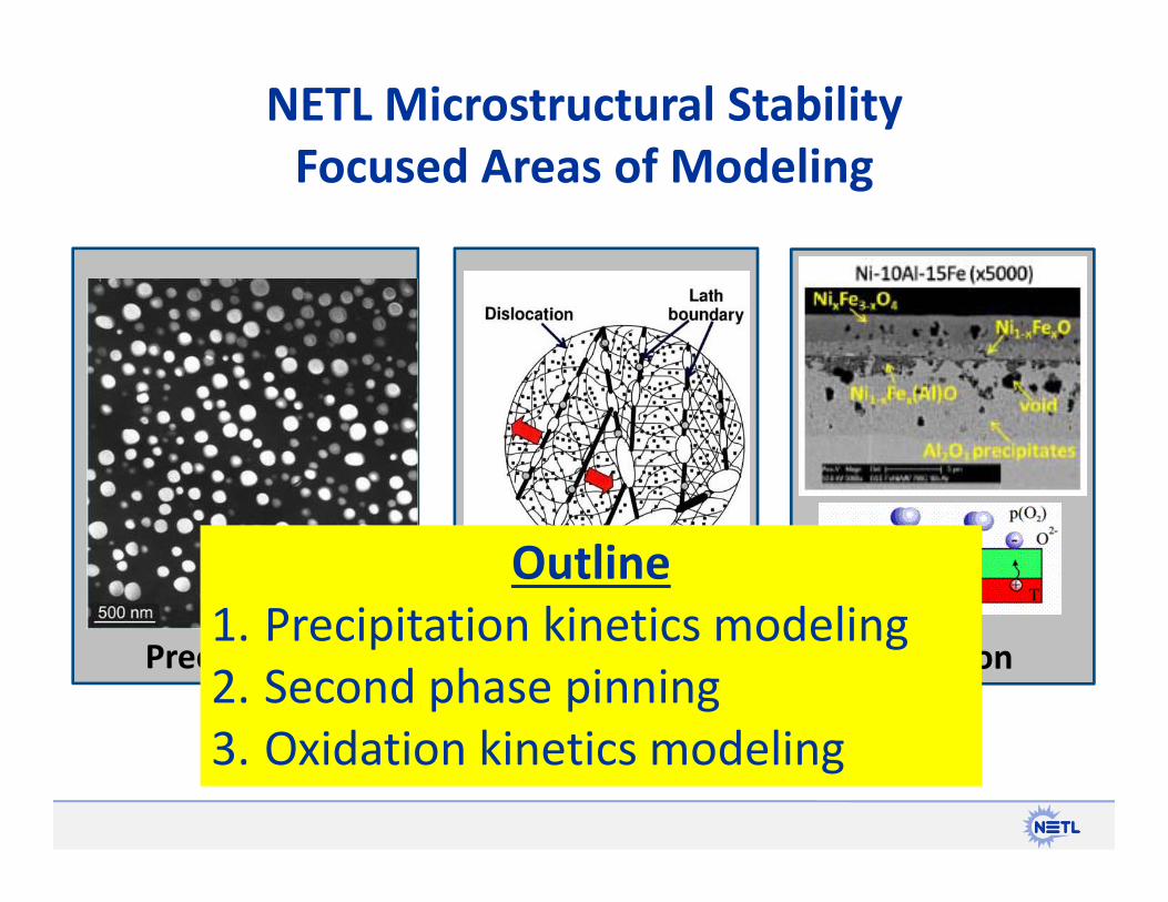
NETL Microstructural Stability Focused Areas of Modeling
Precipitation 2nd Phase Pinning Metal Oxidation
Matrix Strength Grain Boundary Strength Surface Attack

NETL Microstructural Stability Focused Areas of Modeling
Precipitation 2nd Phase Pinning Oxidation
IPT Task 5.4
Microstructure ModelingIPT Task 5.3
Oxidation Modeling
NETL Microstructural Stability Focused Areas of Modeling
Precipitation 2nd Phase Pinning Oxidation
Outline1. Precipitation kinetics modeling2. Second phase pinning 3. Oxidation kinetics modeling
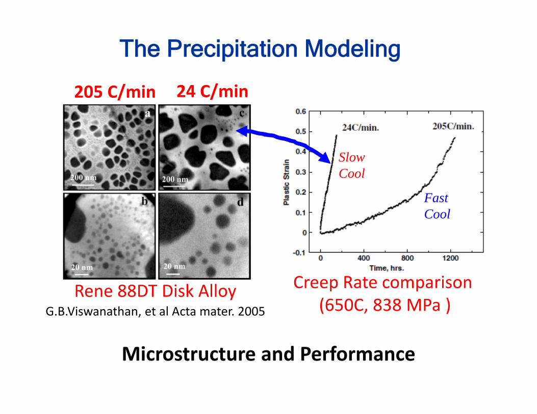
Creep Rate comparison (650C, 838 MPa )G.B.Viswanathan, et al Acta mater. 2005
Rene 88DT Disk Alloy
205 C/min 24 C/min
Microstructure and Performance
Fast Cool
Slow Cool
The Precipitation Modeling

The Challenges
o High volume fraction of precipitates excluding any analytical solutions
o Complex thermal heat treating & thermo mechanical service condition
o Multi‐component & multi‐phase
Phase‐field method has the potential M.E. Gurtin and P.W. Voorhees.
Goal: Develop an engineering tool that can predict precipitation process under representative thermomechanical processing and service conditions
The Precipitation Modeling
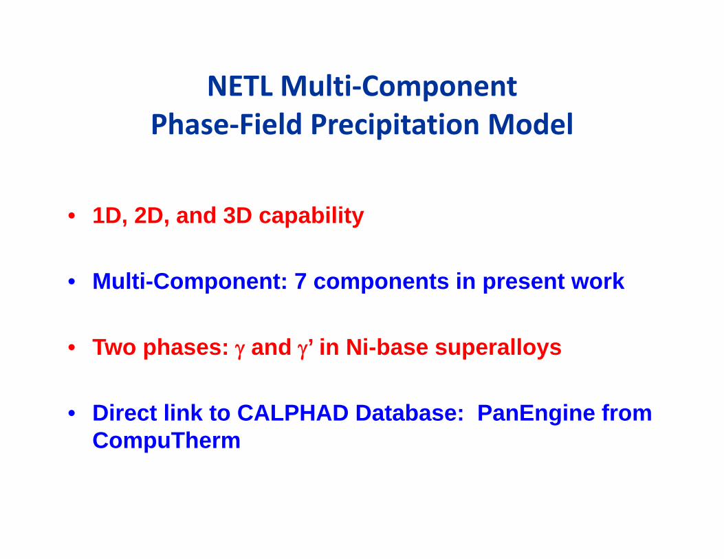
NETL Multi‐Component Phase‐Field Precipitation Model
• 1D, 2D, and 3D capability
• Multi-Component: 7 components in present work
• Two phases: and ’ in Ni-base superalloys
• Direct link to CALPHAD Database: PanEngine from CompuTherm

Time (hr)
0 50 100 150 200
Aver
age
Rad
ius
(nm
)
52
54
56
58
60
62
64
66
68
70
72
74Alloy #1 (Regular Composition)Alloy #2 (Increasing Al)Alloy #3 (Increasing Co)Alloy #4 (Increasing Cr)Alloy #5 (Increasing Mo)Alloy #6 (Increasing Ti)
Haynes 282 Precipitation KineticsAl Co Cr Fe Mo Ti Ni Vol.%
1 1.5 10.0 20.0 1.5 8.5 2.1 Bal 18.86
2 1.8 10.0 20.0 1.5 8.5 2.1 Bal 21.08
3 1.5 11.0 20.0 1.5 8.5 2.1 Bal 18.91
4 1.5 10.0 21.0 1.5 8.5 2.1 Bal 18.97
5 1.5 10.0 20.0 1.5 9.5 2.1 Bal 19.05
6 1.5 10.0 20.0 1.5 8.5 2.5 Bal 21.62
Developing a Virtual Tool for Alloy Chemistry Screening
Baseline alloy

Time (hr)
0 50 100 150 200
Aver
age
Rad
ius
(nm
)
52
54
56
58
60
62
64
66
68
70
72
74Alloy #1 (Regular Composition)Alloy #2 (Increasing Al)Alloy #3 (Increasing Co)Alloy #4 (Increasing Cr)Alloy #5 (Increasing Mo)Alloy #6 (Increasing Ti)
Precipitation Kinetics Modeling Results
Al Co Cr Fe Mo Ti Ni Vol.%
1 1.5 10.0 20.0 1.5 8.5 2.1 Bal 18.86
2 1.8 10.0 20.0 1.5 8.5 2.1 Bal 21.08
3 1.5 11.0 20.0 1.5 8.5 2.1 Bal 18.91
4 1.5 10.0 21.0 1.5 8.5 2.1 Bal 18.97
5 1.5 10.0 20.0 1.5 9.5 2.1 Bal 19.05
6 1.5 10.0 20.0 1.5 8.5 2.5 Bal 21.62
Verifying predictions, work in progress
0.0
25.0
50.0
75.0
100.0
125.0
150.0
0 1000 2000 3000 4000 5000
'Single Num
ber' GP Size (n
m)
Aging Time (hours)
H282‐B & ‐C, Aged at 760°C, Water Quenched
H282‐B
H282‐B <100>
H282‐B‐TBBlank
H282‐C
H282‐C‐TBBlank
Alloy Ni Cr Co Mo Ti Al Fe Mn Si C B ppm
Nominal Bal 18.5‐20.5
9‐11
8‐9
1.9‐2.3
1.38‐1.65
1.5* 0.3* 0.15* 0.04‐0.08
30‐50
H282‐B Bal 19.22 9.86 8.49 2.22 1.27 0.25 0.15 0.08 100H282‐C Bal 19.19 9.85 8.50 1.94 1.54 0.25 0.14 0.08 100
H282B – Alloy # 6 H282C – Alloy 2
• Developed a multicomponent Phase‐Field model that can simulate precipitation kinetics in Ni‐based commercial alloys
• Demonstrated that this model has the potential to be used for composition screening for a more stable precipitation microstructure
Summary of Precipitation Modeling
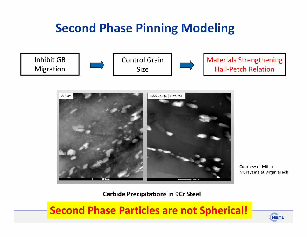
Second Phase Pinning Modeling
Carbide Precipitations in 9Cr Steel
Courtesy of MitsuMurayama at VirginiaTech
Inhibit GB Migration
Control Grain Size
Materials Strengthening Hall‐Petch Relation
Second Phase Particles are not Spherical!
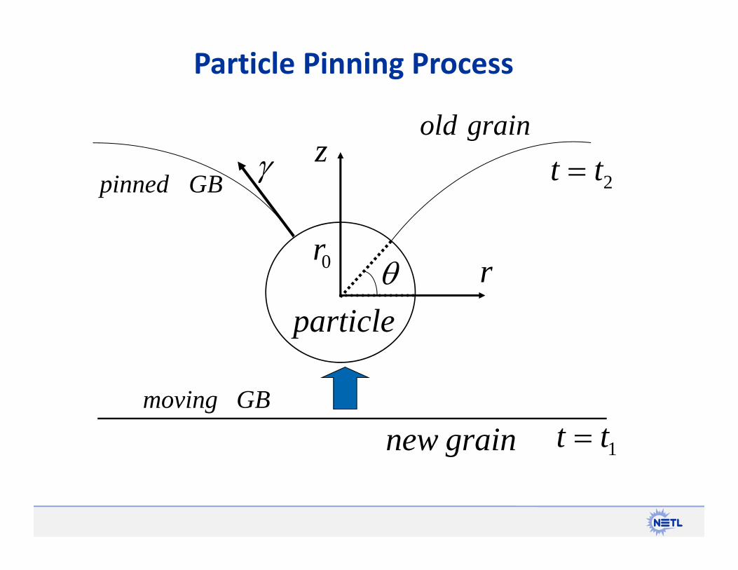
Particle Pinning Process
grainnew
grainold
particle
0r
GBpinned 2tt
1tt GBmoving
z
r

Zenner Particle Pinning Theory
grainnew
grainold
particle
0r
GBpinned 2tt
1tt GBmoving
z
r
sincos2 0rFz
0max rFz
• Spherical second phase particle • Incoherent interfacesThese two constraints are relaxed in this project
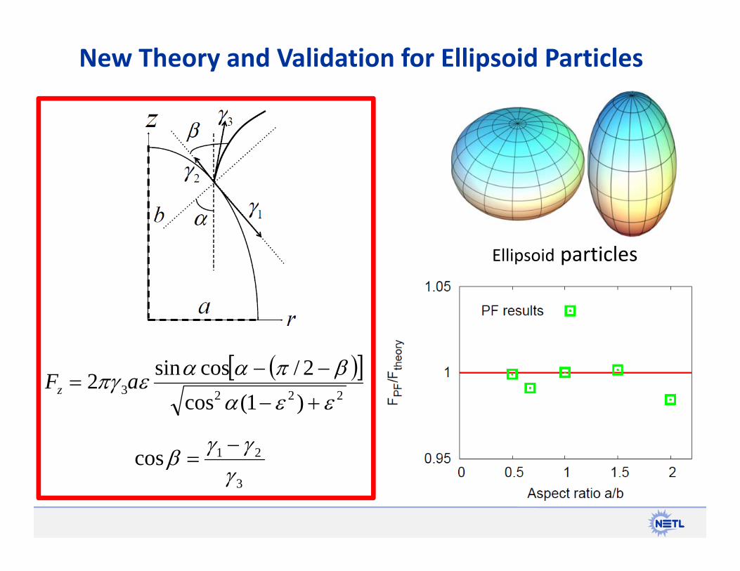
New Theory and Validation for Ellipsoid Particles
Ellipsoid particles
2223
)1(cos2/cossin2
aFz
3
21cos
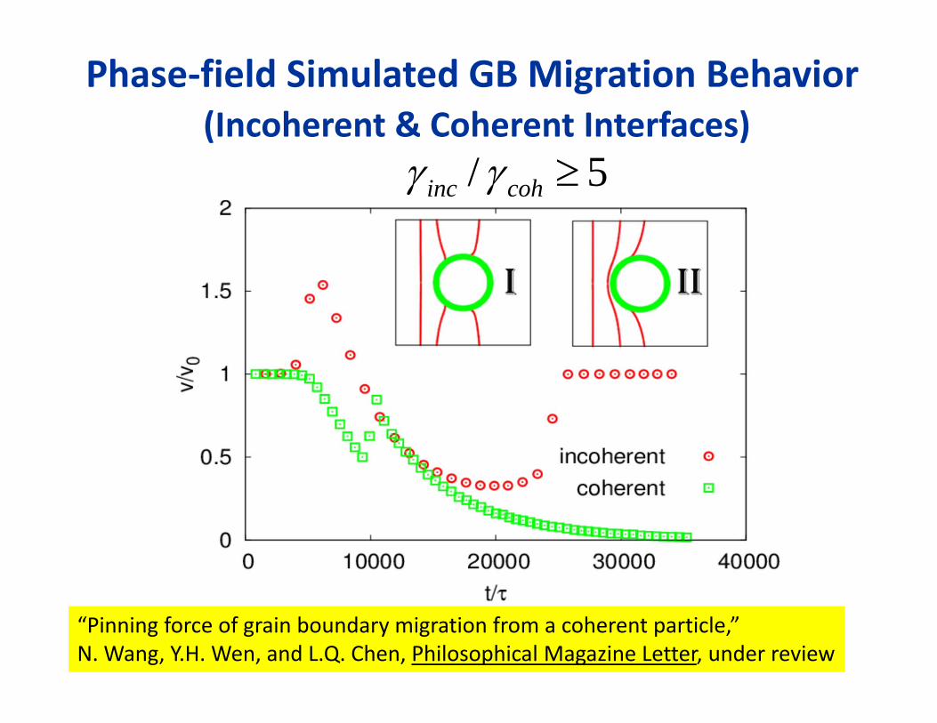
5 / cohinc
Phase‐field Simulated GB Migration Behavior(Incoherent & Coherent Interfaces)
“Pinning force of grain boundary migration from a coherent particle,” N. Wang, Y.H. Wen, and L.Q. Chen, Philosophical Magazine Letter, under review
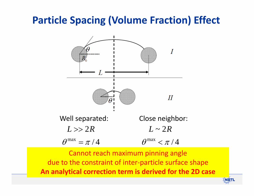
Particle Spacing (Volume Fraction) Effect
Well separated:
4/max
RL 2Close neighbor:
4/max
RL 2~
Cannot reach maximum pinning angle due to the constraint of inter‐particle surface shape
An analytical correction term is derived for the 2D case

Pinning Force Correction at High Volume
Correction to current pinning force theory at high volume fraction validated against PF simulation
“Pinning force from multiple second‐phase particles in grain growth,” N. Wang, Y.H. Wen, and L.Q. Chen, Computational Materials Science, under review

• Developed a first quantitative evaluation for coherent particle pinning force for an ellipsoid particle
• Proposed a large volume fraction pinning force correction and verified via Phase-field simulations
Summary of 2nd Phase Pinning Modeling
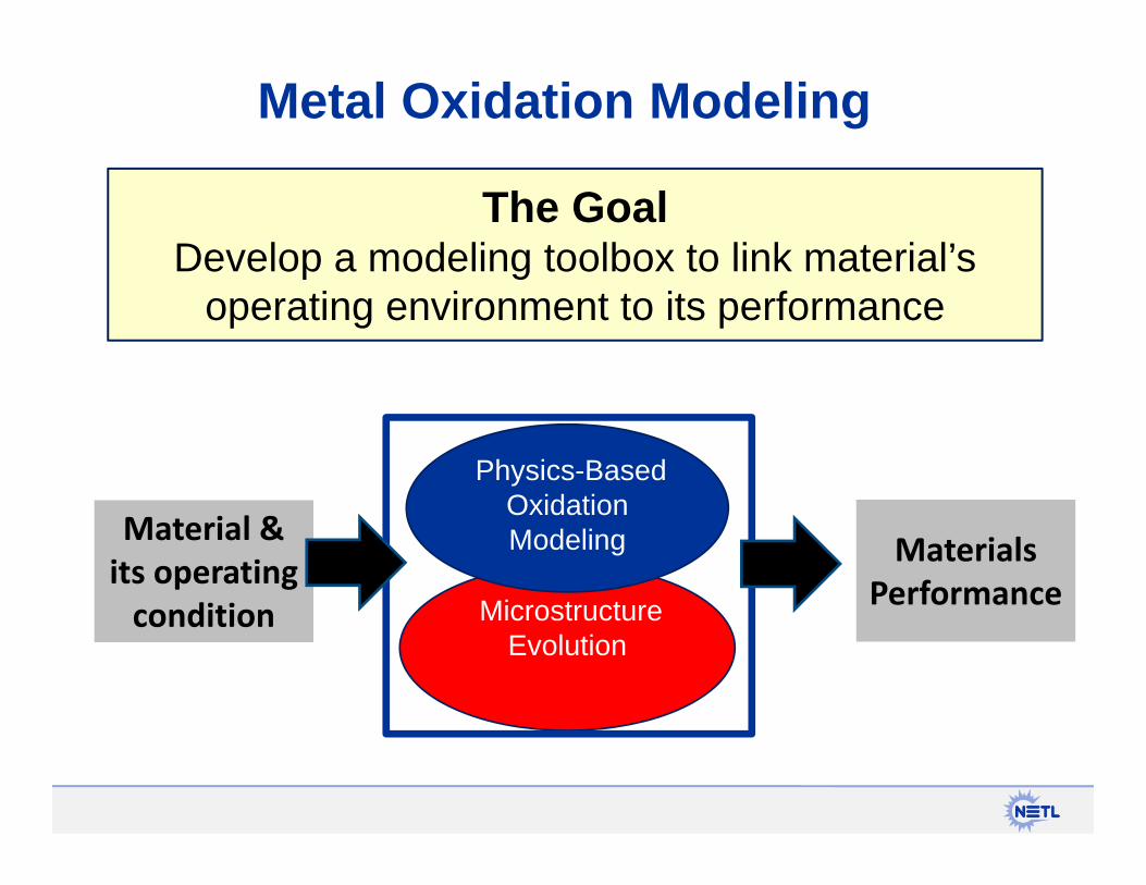
The GoalDevelop a modeling toolbox to link material’s
operating environment to its performance
Metal Oxidation Modeling
MicrostructureEvolution
Physics-Based Oxidation Modeling Materials
Performance
Material & its operating condition
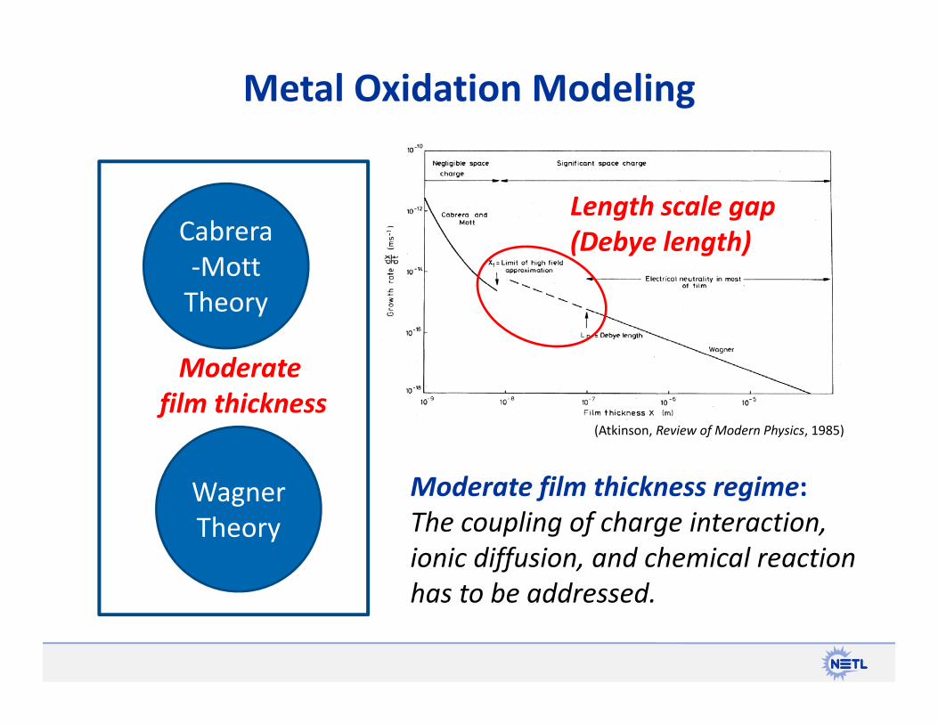
Metal Oxidation Modeling
Cabrera‐Mott Theory
Wagner Theory
Moderate film thickness
Length scale gap (Debye length)
(Atkinson, Review of Modern Physics, 1985)
Moderate film thickness regime:The coupling of charge interaction, ionic diffusion, and chemical reaction has to be addressed.
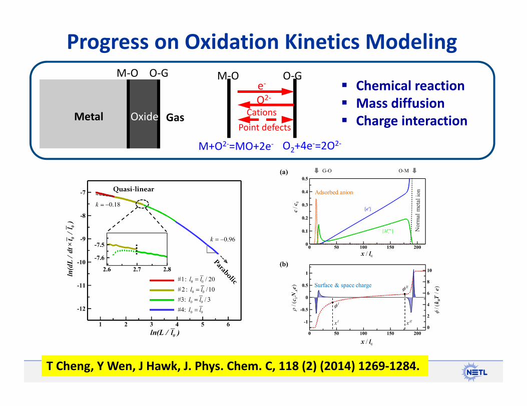
Progress on Oxidation Kinetics Modeling
Metal Oxide Gas
M‐O O‐G
CationsPoint defects
M‐O O‐G
M+O2‐=MO+2e‐ O2+4e‐=2O2‐
e‐O2‐
Chemical reaction Mass diffusion Charge interaction
T Cheng, Y Wen, J Hawk, J. Phys. Chem. C, 118 (2) (2014) 1269‐1284.

Electrostatic potential distribution in a growing oxide film under different
ion/electron mobility ratios
T Cheng, Y Wen, J. Phys. Chem. Letter, under review
• Developed an analytical model for the electric field in the growing oxide for a simpler prototype oxidation reaction
• Verified via comprehensive phase‐field modeling for more sophisticated cases.
• Revealed the electrostatic potential drop across the bulk oxide is limited to ~kBT/e
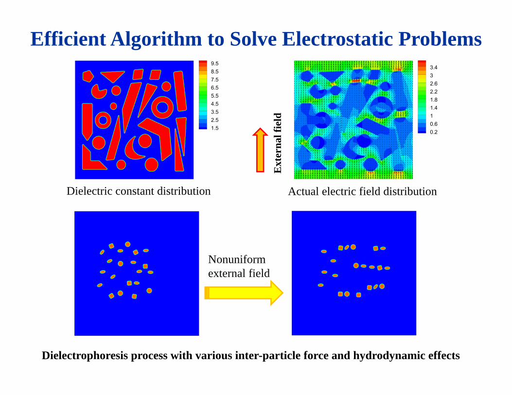
Dielectric constant distribution Actual electric field distribution
Ext
erna
l fie
ld
Efficient Algorithm to Solve Electrostatic Problems
Nonuniformexternal field
Dielectrophoresis process with various inter-particle force and hydrodynamic effects

Summary of Oxidation Kinetics Modeling
• Developed a multiscale simulation capability based on Phase‐Field Method to solve the complex coupling problem that involves transport of charged ions subject to interfacial reactions and long range electrostatic interactions
• Developed an efficient numerical algorithm to solve the charge interaction problem with arbitrary heterogeneity in electric properties
• Further development of the model is necessary to advance this model into a useful tool that can be used to predict the life of a complex alloy
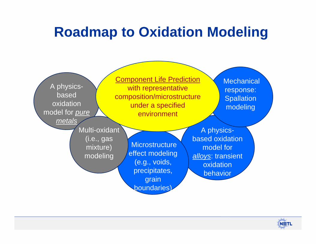
Roadmap to Oxidation Modeling
A physics-based
oxidation model for pure
metalsA physics-
based oxidation model for
alloys: transient oxidation behavior
Microstructure effect modeling
(e.g., voids, precipitates,
grain boundaries)
Multi-oxidant (i.e., gas mixture) modeling
Mechanical response: Spallation modeling
Component Life Prediction with representative
composition/microstructure under a specified
environment

Backup Slides

Lattice Coherency of Pinning ParticlesCoherency loss
GB GBCoherent Incoherent
5 / cohinc ~ incgb Surface energy ~
2 grain
particle
GBpinned
1 grain
Coherent interface
Incoherent interface

Interaction between grain boundary and pinning particle under the influence of interfacial energy only ; Incoherent (left) and coherent (right)
GB shape near a coherent particle with large lattice misfit
PFC Results of Coherent Particle Pinning
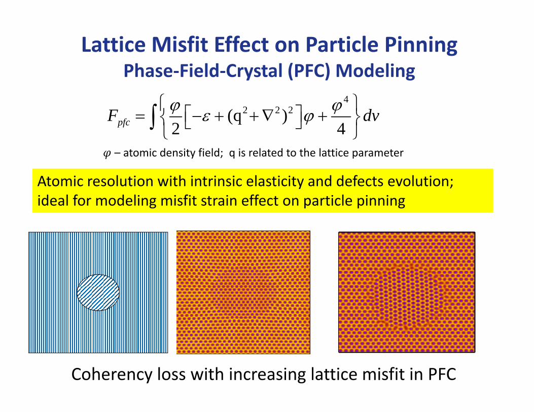
Coherency loss with increasing lattice misfit in PFC
Atomic resolution with intrinsic elasticity and defects evolution; ideal for modeling misfit strain effect on particle pinning
42 2 2(q )
2 4pfcF dv
Lattice Misfit Effect on Particle PinningPhase‐Field‐Crystal (PFC) Modeling
– atomic density field; q is related to the lattice parameter
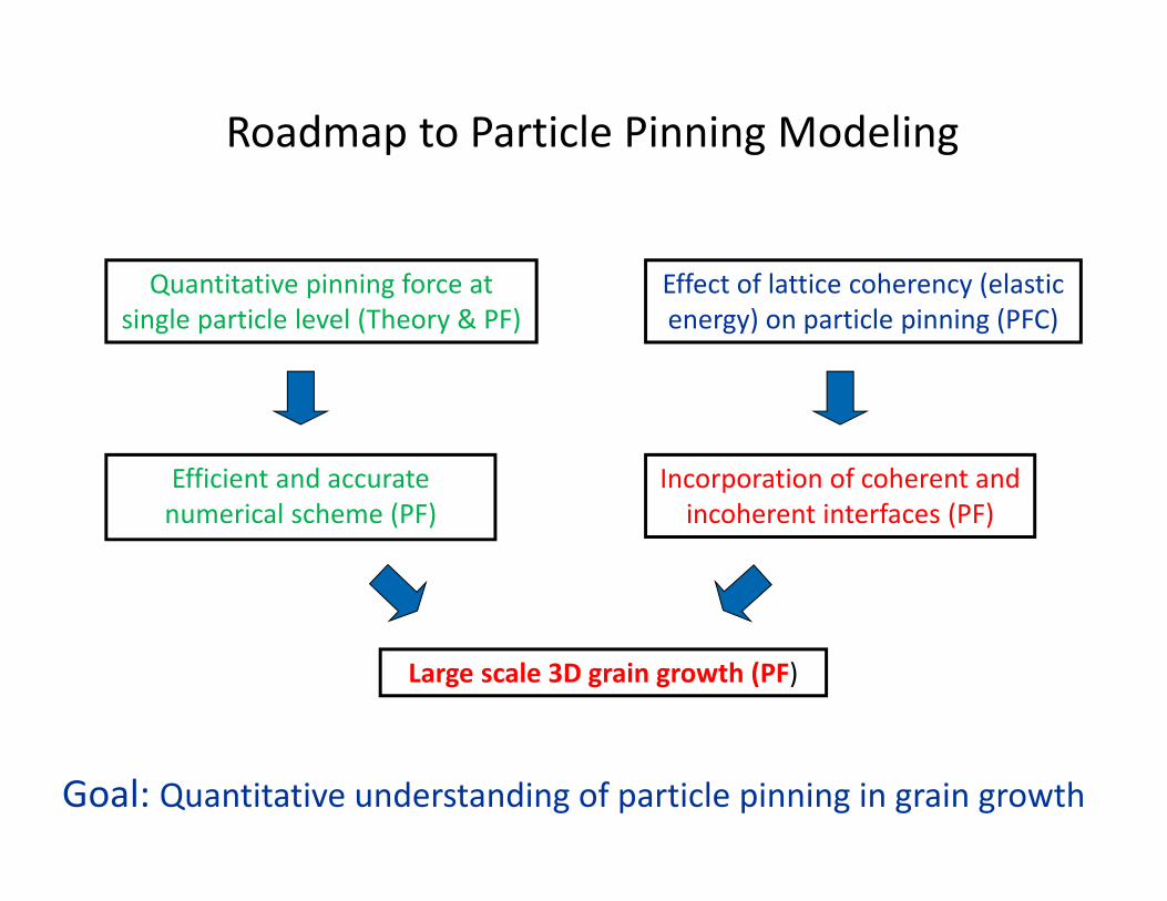
Roadmap to Particle Pinning Modeling
Quantitative pinning force at single particle level (Theory & PF)
Effect of lattice coherency (elastic energy) on particle pinning (PFC)
Large scale 3D grain growth (PF)
Efficient and accurate numerical scheme (PF)
Incorporation of coherent and incoherent interfaces (PF)
Goal: Quantitative understanding of particle pinning in grain growth
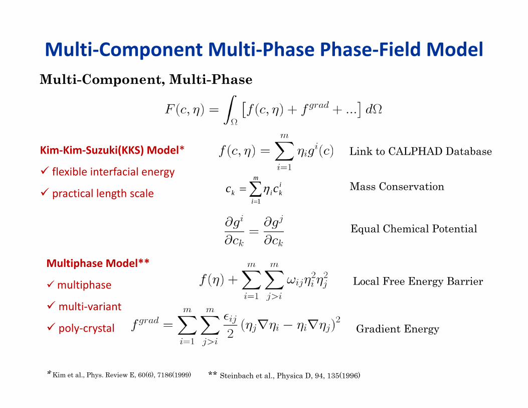
Multi‐Component Multi‐Phase Phase‐Field ModelMulti-Component, Multi-Phase
Kim‐Kim‐Suzuki(KKS) Model*
flexible interfacial energy
practical length scale
* Kim et al., Phys. Review E, 60(6), 7186(1999)
Link to CALPHAD Database
Mass Conservation
Equal Chemical Potential
Multiphase Model**
multiphase
multi‐variant
poly‐crystal
** Steinbach et al., Physica D, 94, 135(1996)
Local Free Energy Barrier
Gradient Energy
ik
m
iik cc
1

Phase‐Field Model: (cont.)
Elastic Effect t due to Lattice Misfit
Vegard’s law
n
mmijij
moijmijij
rXmr
XaXam
1
0000
0000
)()()(
)()(
Composition-dependent eigenstrain

Oxidation Model Description
*
*
[ ] [ ] [ ] [ ]
[ ] [ ] [ ] [ ]
I X
I X
d X k p X X edt
d e k p X X edt
[ ] [ ] [ ][ ]
[ ] [ ][ ]
II
II
d X d M k M Xdt dt
d e k M Xdt
(cf. Standard Deal‐Grove oxidation model)
Boundary condition:Metal phase: electric field inside a conductor should be zero.
(large mobility electrons + background cations) Gas phase: Diffusing species are prohibited to enter

Governing Equations
The electric field, satisfying Poisson’s equation, is solved by an efficient numerical scheme for arbitrary dielectric heterogeneity
12 1 1 1 1 1 1 1 1
22 1 1 1 2 2 2 2 2
33 3 3 3 3
2 21
( ) ( ) ( )
( ) ( ) ( )
( ) ( )
/
I X IIB
I X IIB
B
V II
c eK p c c c K c D c D c zt k Tc eK p c c c K c D c D c zt k Tc eD c D c zt k T
K K c M ft
E
E
E
[X‐]:
[e‐]:
[c+]:
[M]:
Reaction Diffusion + Electromigration
(1 ) ,p q (1 )p q
( )(1 )ii G M ic c
21( ) ( )2
F f dV

1 2 3 4 5 10 15 20 25 30
Simulated film growth rate
Idealized parabolic growth
Film thickness, / DL l
Parabolic growth at the thick film stage and the deviation by the space charge effectwhen the film thickness is approaching the Debye length
pdLk Ldt
Simulated Kinetics vs Wagner Theory
Space charge effe
ct