Embed Size (px)
Citation preview
IWM 2008 CONFERENCE
187
PREDICTING DISSOLVED OXYGEN CONCENTRATION IN A MOBILE BED BIOFILM REACTOR
Diana ROBESCU1∗, Corina MOGA2∗, Dan ROBESCU3*
The paper presents a mathematical model for dissolved oxygen concentration profiles in mobile bed biological reactor. General oxygen dispersion equation was solved numerically. The purpose of the study is to find the optimum dimension, position of the aeration pipes and the percentage of the total volume of the tank occupied by the carrier media for maintaining the oxygen concentration in the limits indicated in the literature. The theoretical results approved the reality in the bioreactor filled with tap water. Further works is now underway to test this model on the pilot installation.
Keywords: biological wastewater treatment, dissolved oxygen concentration, modeling, simulation, biofilm
1. Introduction
The chief objective of the biological wastewater treatment stage is the removal of the non-settleable organic solids from the wastewater. Biological wastewater process is a particularly complex process to which contribute phenomena of different natures such as physical, chemical, biochemical. Underlying these processes is the metabolic activity of some microorganisms capable to degrade organic substances, converting them to carbon dioxide and water. The feasibility of the biological process resides in the possibility of maintaining the degrading phenomena over a period of time in the specific conditions of the reactor in which the process takes place. There are a large variety of technologies for biological wastewater treatment. Technology with MBBR (mobile bed biofilm reactor) was developed by The Norwegian University of Science and Technology and Kaldnes Miljoteknologi A/S of Norway, [8]. This system consists of a reactor vessel containing mixed liquor suspended solids with specially designed small floating carrier media suspended and kept in constant circulation. A screen is provided at the outfall end of the reactor to keep media from clogging the effluent spout or passing out of the reactor. The media are engineered in a wheel shape and is slightly positively buoyant, allowing a small amount of water flow (created by adding air to the process) to circulate the media throughout the vessel. Oxygen and food (ammonia and nitrite) gives the bacteria the
1∗ Assoc.Prof., Hydraulics, Hydraulic Machinery and Environmental Engineering Dept., University POLITEHNICA of Bucharest, Romania 2∗ PhD. Student, Hydraulics, Hydraulic Machinery and Environmental Engineering Dept., University POLITEHNICA of Bucharest, Romania 3* Prof., Hydraulics, Hydraulic Machinery and Environmental Engineering Dept., University POLITEHNICA of Bucharest, Romania
PREDICTING DISSOLVED OXYGEN CONCENTRATION IN A MOBILE BED BIOFILM REACTOR
188
means to grow, whilst the Kaldnes media provides maximum surface area for the bacteria to colonize and produce biofilm.
This technology is used for new or for upgrading existed plants. Also, there are compact systems for wastewater treatment that used this technology.
Dissolved oxygen concentration is very important in the aerobic biological wastewater treatment processes. There are a lot of studies in this field, some of them to predict the aeration efficiency of various equipments [5], [6], others to control the aeration stage using dissolved oxygen concentration [3]. Some models for oxygen mass-transfer are presented in [2], [4] and [7].
This paper proposes a model for determining oxygen concentration profiles in the bioreactor using the dispersion equation. The theoretical simulation study takes into account the geometry of a laboratory installation. A customize program, using FlexPDE software, is written for numerically solving the dispersion equation. Various scenarios is taken into account in order to obtain the optimum dimension and position of the aeration pipes for maintaining oxygen concentration in the limits 5-7 mg/l in the whole bioreactor, as the literature indicates, [10].
2. Basic equations
A parallelepiped–shaped biological tank with longitudinal flow and with aeration from the bottom is considered (fig. 1).
The air is dispersed in the water using pneumatic equipment consisting of two pipes with perforations, connected to a blower.
The following hypotheses are taken into account: (I) hydraulically permanent motion; (II) unidirectional horizontal motion; (III) no stationary system as to mass transfer; (IV) perfect mixing in biological tank.
The general oxygen dispersion equation is:
B z x H Q h l y L
Fig.1 Biological reactor
Q- water flowrate; B- width of the reactor; H – depth of the reactor; L – length of the reactor; h-
position from the bottom of the aeration equipment; l- length of the aeration pipes
PREDICTING DISSOLVED OXYGEN CONCENTRATION IN A MOBILE BED BIOFILM REACTOR
189
( ) ( ) ( ) +⎟⎟⎠
⎞⎜⎜⎝
⎛∂∂
∂∂
+⎟⎟⎠
⎞⎜⎜⎝
⎛∂∂
∂∂
=∂∂
+∂∂
+∂∂
+∂∂
yC
yxC
xCw
zCv
yCu
xtC
yx εε
( )tzyxSzC
yC
xCD
zC
z mz ,,,2
2
2
2
2
2+⎟⎟⎠
⎞⎜⎜⎝
⎛
∂
∂+
∂
∂+
∂
∂+⎟⎟⎠
⎞⎜⎜⎝
⎛∂∂
∂∂ ε (1)
where C – the oxygen concentration, εx – the axial dispersion coefficient, εy - the transversal dispersion coefficient, εz – the vertical dispersion coefficient, S – the consumption of oxygen, Dm – the mass diffusion coefficient. The upper bar means that the respective quantities are averaged due to the turbulence.
Obtaining a complete solution of the Eq.1 seems hopeless, so that the following additional modeling hypothesis can be formulated:
- planar movement process (water flows on the Ox-axis with the constant velocity
BAQu =0 , Q – water flowrate, B – wide of the tank, A – horizontal area of the tank; gas
bubbles flow along Oy – from now on standing for the vertical axis instead of Oz); - the molecular diffusion is negligible against the turbulent convective one, so the
term DmΔC can be dropped; - the terms for the transversal turbulent dispersion are neglected because their
very small values against similar phenomena on Ox and Oy; -due to upward movement of air bubbles occurs a gas lift phenomenon that
enhances mixing and oxygen transfer into water; - in the Eq.1, the component v of velocity is replaced with the raising velocity of
air bubbles, w; - the axial dispersion occurs due to the multiphase flow along Ox axis and
upward movement of gas bubbles; - there is perfect mixing of phases. The dispersion equation in these conditions becomes:
( ) ( ) ),,( tyxSyC
yxC
xCw
yCu
xtC
yx +⎟⎟⎠
⎞⎜⎜⎝
⎛∂∂
∂∂
+⎟⎟⎠
⎞⎜⎜⎝
⎛∂∂
∂∂
=∂∂
+∂∂
+∂∂ εε (2)
Since the air is introduced at the bottom of the tank by the pneumatic equipment, it is considered that εx<εy. The oxygen concentration in water is the result of two processes: a) the oxygen mass transfer from the air into the water due to air bubbles movement; b) the oxygen consumption for the biochemical oxidation of the organic matter. The last right term of the equation takes into account the oxygen concentration decay because of the consumption reactions. It is considered the first-order decay term for the oxygen consumption:
( ) ( ) CkyC
yxC
xCw
yCu
xtC
yx ⋅−⎟⎟⎠
⎞⎜⎜⎝
⎛∂∂
∂∂
+⎟⎟⎠
⎞⎜⎜⎝
⎛∂∂
∂∂
=∂∂
+∂∂
+∂∂ εε (3)
PREDICTING DISSOLVED OXYGEN CONCENTRATION IN A MOBILE BED BIOFILM REACTOR
190
3. Numerical integration results
For the numerically integration of the Eq. (3) a customized program is written using FlexPDE software, [4]. FlexPDE is a "scripted finite element model builder and numerical solver". It means that from a script written by the user, FlexPDE performs the operations necessary to turn a description of a partial differential equations system into a finite element model, solve the system, and present graphical and tabular output of the results. The user can edit the script, run the problem and observe the output, then re-edit and re-run repeatedly without leaving the FlexPDE application environment. FlexPDE has no pre-defined problem domain or equation list. The choice of partial differential equations is totally up to the user, [9].
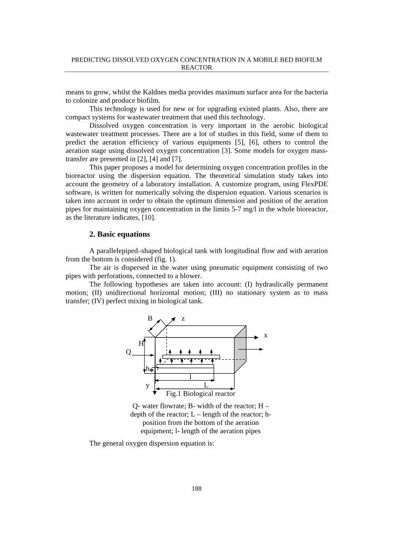
The constants in the equation (3) are determined from the design relationship for a bioreactor with geometrical dimensions H=B=L =2 m and water flowrate Q = 100 m3/h: u=0.003 m/s, w=0.3 m/s, εx=0.3 m2/s εy=2 m2/s, k=0.2 s-1. Initially the dissolved oxygen concentration in the liquid is C=2 mg/l. The pipes for air dispersion are put on the bottom of the tank and they have orifices of 2 mm diameter, horizontally distributed at 7 mm. The aeration produces medium bubbles which provide the necessary mixing and maintain the dissolved oxygen level at 5 - 7 mg/l. Bubbles start to flow upwards from the bottom of the tank at time zero.
A lot of simulations is made to determine the optimum length of aeration pipe and the position of the pneumatic equipment so that the oxygen concentration in the whole volume of bioreactor to be around 5– 7 mg/l. Some theoretical results are presented in fig.2 – 10.
Mobile Bed Biofilm Reactor - oxygen profiles
MBBR oxygen var 2: Cycle=80 Time= 2500.0 dt= 529.19 p2 Nodes=4756 Cells=2227 RMS Err= 6.8e-5Integral= 29.88000
10:05:23 10/22/08FlexPDE 5.0.9
X
0. 0.3 0.6 0.9 1.2 1.5 1.8 2.1
Y
0.
0.3
0.6
0.9
1.2
1.5
1.8
2.1
ox
C
10.2 9.90 9.60 9.30 9.00 8.70 8.40 8.10 7.80 7.50 7.20 6.90 6.60 6.30 6.00 5.70 5.40
Fig.2. Dissolved oxygen profiles for l=1 m, h=0.02 m
PREDICTING DISSOLVED OXYGEN CONCENTRATION IN A MOBILE BED BIOFILM REACTOR
191
Mobile Bed Biofilm Reactor - oxygen profiles
MBBR oxygen var 2: Cycle=70 Time= 805.58 dt= 207.59 p2 Nodes=5939 Cells=2780 RMS Err= 7.4e-5Integral= 31.90178
10:22:05 10/22/08FlexPDE 5.0.9
X
0. 0.3 0.6 0.9 1.2 1.5 1.8 2.1
Y
0.
0.3
0.6
0.9
1.2
1.5
1.8
2.1
ox
C
10.2 9.90 9.60 9.30 9.00 8.70 8.40 8.10 7.80 7.50 7.20 6.90 6.60 6.30 6.00 5.70 5.40 5.10 4.80 4.50 4.20 3.90
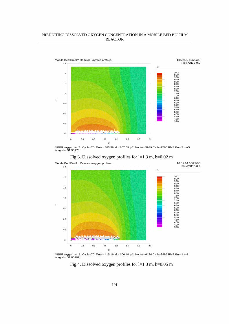
Fig.3. Dissolved oxygen profiles for l=1.3 m, h=0.02 m
Mobile Bed Biofilm Reactor - oxygen profiles
MBBR oxygen var 2: Cycle=70 Time= 415.16 dt= 106.48 p2 Nodes=6124 Cells=2885 RMS Err= 1.e-4Integral= 31.80909
10:31:14 10/22/08FlexPDE 5.0.9
X
0. 0.3 0.6 0.9 1.2 1.5 1.8 2.1
Y
0.
0.3
0.6
0.9
1.2
1.5
1.8
2.1
ox
C
10.2 9.90 9.60 9.30 9.00 8.70 8.40 8.10 7.80 7.50 7.20 6.90 6.60 6.30 6.00 5.70 5.40 5.10 4.80 4.50 4.20 3.90
Fig.4. Dissolved oxygen profiles for l=1.3 m, h=0.05 m
PREDICTING DISSOLVED OXYGEN CONCENTRATION IN A MOBILE BED BIOFILM REACTOR
192
Mobile Bed Biofilm Reactor - oxygen profiles
MBBR oxygen var 2: Cycle=70 Time= 647.63 dt= 166.94 p2 Nodes=5029 Cells=2370 RMS Err= 9.4e-5Integral= 29.83513
13:57:36 10/22/08FlexPDE 5.0.9
X
0. 0.3 0.6 0.9 1.2 1.5 1.8 2.1
Y
0.
0.3
0.6
0.9
1.2
1.5
1.8
2.1
ox
C
10.2 9.90 9.60 9.30 9.00 8.70 8.40 8.10 7.80 7.50 7.20 6.90 6.60 6.30 6.00 5.70 5.40 5.10
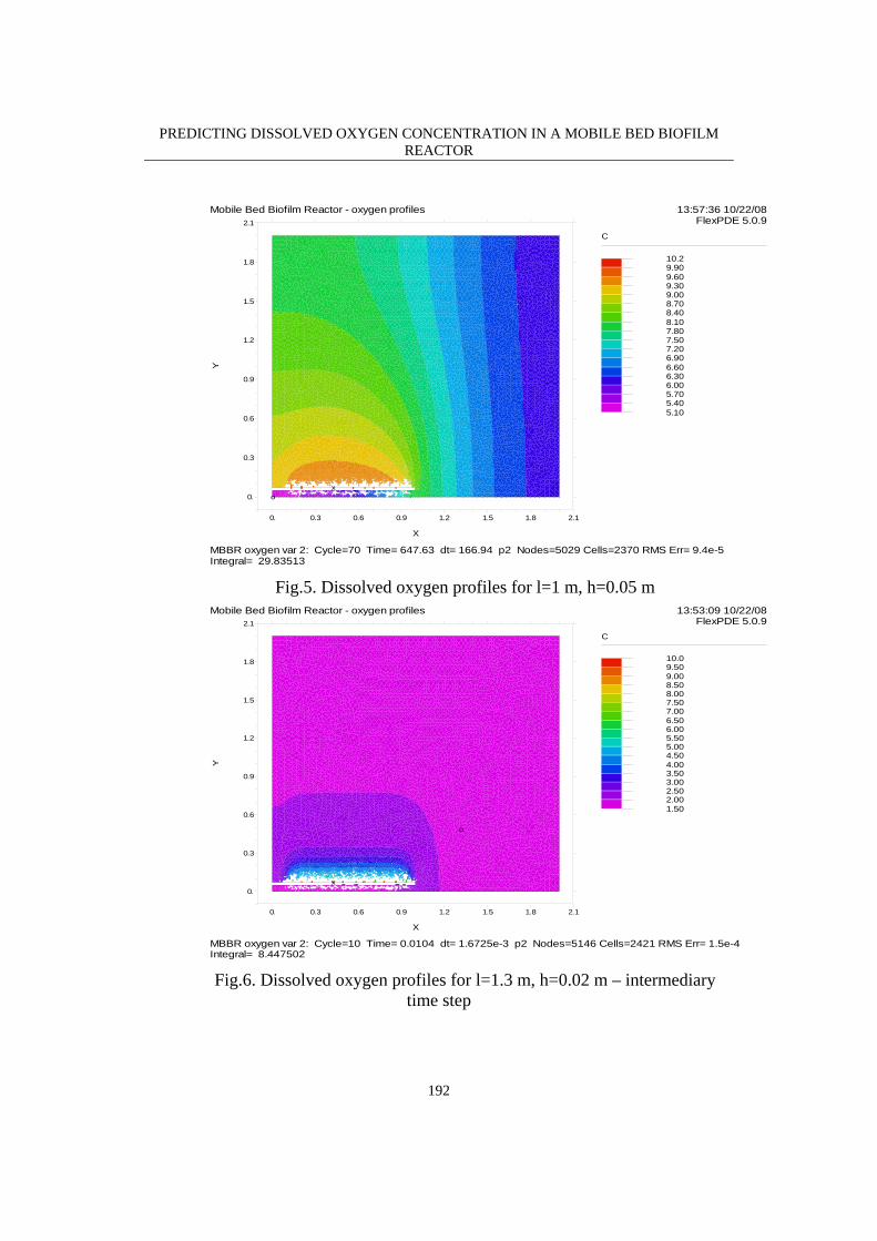
Fig.5. Dissolved oxygen profiles for l=1 m, h=0.05 m
Mobile Bed Biofilm Reactor - oxygen profiles
MBBR oxygen var 2: Cycle=10 Time= 0.0104 dt= 1.6725e-3 p2 Nodes=5146 Cells=2421 RMS Err= 1.5e-4Integral= 8.447502
13:53:09 10/22/08FlexPDE 5.0.9
X
0. 0.3 0.6 0.9 1.2 1.5 1.8 2.1
Y
0.
0.3
0.6
0.9
1.2
1.5
1.8
2.1
o
x
C
10.0 9.50 9.00 8.50 8.00 7.50 7.00 6.50 6.00 5.50 5.00 4.50 4.00 3.50 3.00 2.50 2.00 1.50
Fig.6. Dissolved oxygen profiles for l=1.3 m, h=0.02 m – intermediary
time step
PREDICTING DISSOLVED OXYGEN CONCENTRATION IN A MOBILE BED BIOFILM REACTOR
193
Mobile Bed Biofilm Reactor - oxygen profiles
MBBR oxygen var 2: Cycle=20 Time= 0.0658 dt= 0.0133 p2 Nodes=5142 Cells=2419 RMS Err= 1.3e-4Integral= 1.247427
13:53:09 10/22/08FlexPDE 5.0.9
X
0.5 0.6 0.7 0.8 0.9 1.
Y
0.
0.1
0.2
0.3
0.4
0.5
ox
Czoom(0.5,f-0.05,0.5,0.5)
10.0 9.50 9.00 8.50 8.00 7.50 7.00 6.50 6.00 5.50 5.00 4.50 4.00 3.50 3.00 2.50 2.00 1.50
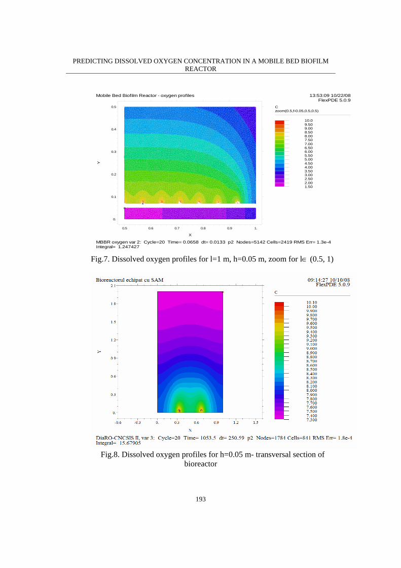
Fig.7. Dissolved oxygen profiles for l=1 m, h=0.05 m, zoom for l∈ (0.5, 1)
Fig.8. Dissolved oxygen profiles for h=0.05 m- transversal section of
bioreactor
PREDICTING DISSOLVED OXYGEN CONCENTRATION IN A MOBILE BED BIOFILM REACTOR
194
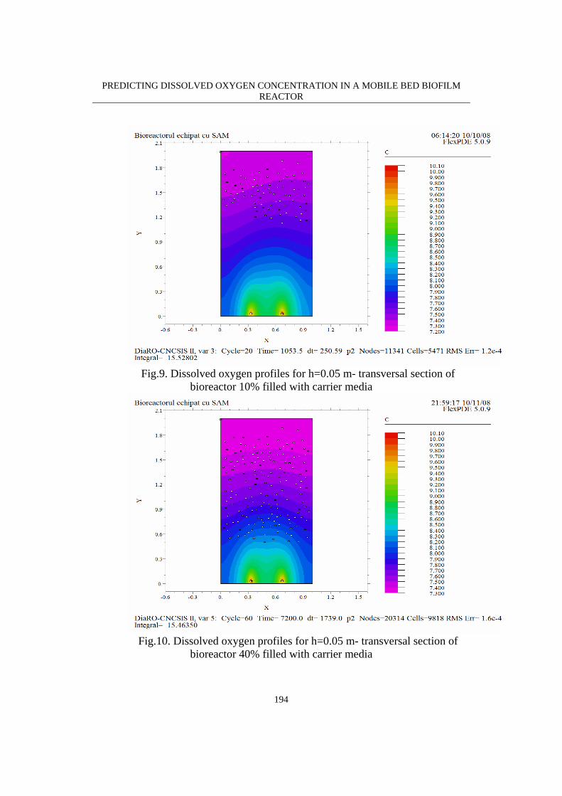
Fig.9. Dissolved oxygen profiles for h=0.05 m- transversal section of
bioreactor 10% filled with carrier media
Fig.10. Dissolved oxygen profiles for h=0.05 m- transversal section of
bioreactor 40% filled with carrier media
PREDICTING DISSOLVED OXYGEN CONCENTRATION IN A MOBILE BED BIOFILM REACTOR
195
From the simulation results, fig. 2 – 7, it could be observed that the optimum
length of the aeration pipes is around 1.3 m. For a smaller length there are zones in bioreactor where oxygen concentration is below limits. The optimum distance from the bottom where the pipes can be placed is 0.05 m, otherwise the oxygen concentration below the aeration pipes is too low. Fig. 8 – 10 are shown that filling the bioreactor with carrier media leads to smaller oxygen concentration near surface as the concentration of carrier media increase. As a consequence, the air flowrate should be increase too, in order to maintain necessary oxygen level in the whole tank.
4. Conclusions
In this paper the dissolved oxygen concentration profiles for various hypotheses is predicted. Mathematical modeling of dissolved oxygen concentration allows identifying the zones in bioreactor with oxygen concentration below the limits and choosing the appropriate dimension and position for aeration pipe which leads to a well-operated tank. Also, the air flow rate supplied by the blower should be fitted with the percentage of the tank occupied by the carrier media. Further works is now underway to test this model on the pilot installation. The results can be used in the optimization and control of the biological wastewater treatment operation and in the design stage for choosing the appropriate disposal of the aeration equipment in the tank.
R E F E R E N C E S
1. Jia-Ming C., Cheng-Fu Y., Oxygen Transfer Modeling of Diffused Aeration Systems, Eng. Chem. Res., 36 (12), pp. 5447 -5453, 1997
2. Liao Y. C., Lee D. J., Estimation of oxygen transfer rate in sequencing batch reactor, Water Science and Technology, Vol. 34, No. 3-4, pp. 413–420, 1996
3. Lindberg C.-F., Carlsson B., Estimation of the respiration rate and oxygen transfer function utilizing a slow do sensor, Water Science and Technology, Vol 33, No 1, pp 325–333, 1996
4. Robescu Diana, Lanyi S., Verestoy A., Robescu D., Modeling and simulation of wastewater processes (in Romanian), Technical Publishing House, Bucharest, 2004
5. Rodgers M., Zhan Xin-Min, Casey A.,Water, Air, & Soil Pollution, Volume 151, Numbers 1-4, pp. 165-178, 2004
6. Wagner M. R., Pöpel H. J., Oxygen transfer and aeration efficiency - influence of diffuser submergence, diffuser density, and blower type, Water Science and Technology, Vol. 38 No. 3, pp. 1–6, 1998
7. Wiesmann U., Su Choi I., Dombrowski E.M., Fundamentals of biological wastewater treatment, Wiley-VCH, 2007
8. www.anoxkaldnes.com 9. www.pdesolutions.com 10. www.stowa-selectedtechnologies.nl

PREDICTING DISSOLVED OXYGEN CONCENTRATION IN A MOBILE BED BIOFILM REACTOR
196


![Dissolved Oxygen [DO]](https://img.pdfslide.us/doc/110x75/5a6721977f8b9ab12b8b464b/dissolved-oxygen-do.jpg)