Embed Size (px)
Citation preview
! Read this manual entirely. When you see this symbol, the subsequent instructions and warnings are serious - follow without exception. Your life and the lives of others depend on it!
Cover illustration may show optional equipment not supplied with standard unit.
© Copyright 1998 Printed
P.O. Box 5060 ● Salina, Kansas 67402-5060Manufacturing, Inc.
Predelivery Instructions
160-243M
Models ADI334 and ADI345
Air Drill Implement
14576
06/03/98

Table of Contents
© Copyright 1997 All rights Reserved
Great Plains Manufacturing, Inc. provides this publication “as is” without warranty of any kind, either expressed or implied. While every precaution has been taken in the preparation of this manual, Great Plains Manufacturing, Inc. assumes no responsibility for errors or omissions. Neither is any liability assumed for damages resulting from the use of the informa-tion contained herein. Great Plains Manufacturing, Inc. reserves the right to revise and improve its products as it sees fit. This publication describes the state of this product at the time of its publication, and may not reflect the product in the future.
Great Plains Manufacturing, Incorporated TrademarksThe following are trademarks of Great Plains Mfg., Inc.: Application Systems, Ausherman, Land Pride, Great Plains
All other brands and product names are trademarks or registered trademarks of their respective holders.
Printed in the United States of America.
Great Plains Mfg., Inc.
Table of Contents
Models ADI334 and ADI345 Air Drill Implement 160-243M 4/7/04
Important Safety Information . . . . . . . . . . . . . . . . . 1Safety Notations. . . . . . . . . . . . . . . . . . . . . . . . . . 1Safety Rules. . . . . . . . . . . . . . . . . . . . . . . . . . . . . 1
Introduction. . . . . . . . . . . . . . . . . . . . . . . . . . . . . . . . 2Description of Unit . . . . . . . . . . . . . . . . . . . . . . . . 2Using This Manual . . . . . . . . . . . . . . . . . . . . . . . . 2Assembly and Setup Assistance . . . . . . . . . . . . . 2
Section 1 Assembly . . . . . . . . . . . . . . . . . . . . . . . . . 3Tools Required . . . . . . . . . . . . . . . . . . . . . . . . . . . 3Pre-Assembly Checklist . . . . . . . . . . . . . . . . . . . . 3Assemble Implement Frame . . . . . . . . . . . . . . . . 3Flex Limiter Bars . . . . . . . . . . . . . . . . . . . . . . . . . 4Lift Cylinder Hydraulic Hoses . . . . . . . . . . . . . . . . 4Fold Cylinders . . . . . . . . . . . . . . . . . . . . . . . . . . . 7
Section 2 Setup . . . . . . . . . . . . . . . . . . . . . . . . . . . . . 9Hitching Cart to Implement . . . . . . . . . . . . . . . . . . 9Bleeding the Lift Hydraulics . . . . . . . . . . . . . . . . 10Bleeding the Folding Hydraulics . . . . . . . . . . . . . 11Leveling Frame Side-to-Side. . . . . . . . . . . . . . . . 12
45-Foot Drill . . . . . . . . . . . . . . . . . . . . . . . . . 1234-Foot Drill . . . . . . . . . . . . . . . . . . . . . . . . . 13
Distribution Towers and Hoses . . . . . . . . . . . . . . 14Primary Distribution Hoses . . . . . . . . . . . . . . . . . 16Secondary Hoses . . . . . . . . . . . . . . . . . . . . . . . . 16
Appendix . . . . . . . . . . . . . . . . . . . . . . . . . . . . . . . . . 21Tire Inflation Chart . . . . . . . . . . . . . . . . . . . . . . . 21Torque Values Chart for Common Bolt Sizes . . . 21

1
Important Safety Information
4/7/04 Models ADI334 and ADI345 Air Drill Implement 160-243M
Great Plains Mfg., Inc.
Important Safety Information
For your safety, thoroughly read “Important Safety Informa-tion” and “Operating Instructions” in the operator’s manual before proceeding.
Safety NotationsThe SAFETY ALERT SYMBOL indicates there is a potential hazard to personal safety involved and extra safety precautions must be taken. When you see this symbol, be alert and carefully read the message that follows it. In addition to design and con-figuration of equipment, hazard control and accident preven-tion are dependent upon the awareness, concern, prudence and proper training of personnel involved in the operation, trans-port, maintenance and storage of equipment.
Watch for the following safety notations throughout these in-structions and the operator’s manual.
! DANGER!Indicates an imminently hazardous situation which, if not avoided, will result in death or serious injury. This signal word is limited to the most extreme situations.
! WARNING!Indicates a potentially hazardous situation which, if not avoid-ed, could result in death or serious injury.
! CAUTION!Indicates a potentially hazardous situation which, if not avoid-ed, may result in minor or moderate injury. It may also be used to alert against unsafe practices.
Safety RulesMost accidents are the result of negligence, carelessness or failure to follow safety precautions. Though your implement is designed with many built-in safety features, safety precautions are mandatory to prevent accidents.
!

2
Introduction
Models ADI334 and ADI345 Air Drill Implement 160-243M 4/7/04
Great Plains Mfg., Inc.
Introduction
An operator’s manual is also provided with the new ma-chine. Read and understand “Important Safety Informa-tion” and “Operating Instructions” in the operator’s manual before assembling the machine. As a reference, keep the operator’s manual on hand while assembling.
The information in this manual is current at printing. Some parts may change to assure top performance.
DefinitionsRight and left as used in this manual are determined by facing the direction the machine will travel while in use un-less otherwise stated.
IMPORTANT: A crucial point of information related to the preceding topic. For safe and correct operation, read and follow the directions provided before continu-ing.
NOTE: Useful information related to the preceding topic.
Assembly and Setup AssistanceTo order additional dealer assembly instructions or opera-tor’s and parts manuals, write to the following address. In-clude model numbers in all correspondence.
If you do not understand any part of this manual or have other assembly or setup questions, assistance is avail-able. Contact
Product SupportGreat Plains Mfg. Inc., Service Department
PO Box 5060Salina, KS 67402-5060
Great Plains Manufacturing wants you to be satisfied with any new machine delivered by the Great Plains Trucking network. To ease the assembly task and produce a prop-erly working machine, read this entire manual before as-sembling or setting up new equipment.
Description of UnitThe three-rank air drill implement is a towed seeding im-plement used with a Great Plains air-drill cart. Seed is de-livered by a pressurized air stream to the floating-hoe openers via primary seed hoses, distribution towers and secondary seed hoses.
The implement has a working width of 34 or 45 feet. The implement has three ranks of staggered openers for easy residue flow. Opener depth is controlled by a hydraulic stop. Press wheels follow the openers to firm and close the seedbed. An electric-clutch drive with an adjustable height switch turns seeding off automatically for headland turns.
Openers and press wheels are spaced over four frame sections on the 34-foot or six sections on the 45-foot im-plement. Floating arms link the cart to the implement, al-lowing the implement to move independently of the tractor and cart for increased front-to-rear flexibility.
The implement folds to a transport height of 15 feet, eight inches (45-foot drill) or 13 feet, two inches (34-foot drill). Rear castor wheels are used for transport and field turns and are lifted for seeding.
Using This ManualThis manual was written to help you assemble and pre-pare the new machine for the customer. The manual in-cludes instructions for assembly and set up. Read this manual and follow the recommendations for safe, efficient and proper assembly and setup.

3
Section 1 Assembly
4/7/04 Models ADI334 and ADI345 Air Drill Implement 160-243M
Great Plains Mfg., Inc.
Section 1 Assembly
This section covers dealer requirements for assembly. As the dealer, it is your responsibility to unload, assemble and prepare the implement for use.
The implement is shipped via flat bed truck. It is not fully assembled. Unload all equipment before beginning as-sembly. Do not attempt any assembly work while the im-plement is on the truck.
The following are step-by-step instructions for assembling the implement. Each heading is a step in the assembly process. Begin with Tools Required and Pre-Assembly Checklist to ensure you have all necessary parts and equipment at hand. Then proceed with Assemble Imple-ment Frame. Follow each step to make the job as quick and safe as possible and produce a properly working ma-chine.
Tools Required• Forklift or overhead hoist with 6,500-pound capacity
• A tractor of sufficient size and horsepower with remote hydraulics. Refer to Tractor Requirements, “Setup,”page 9.
• General hand tools
• Jack stands or blocks and safety chain
NOTE: You will need about 12 gallons of hydraulic oil to re-fill the tractor hydraulic reservoir after initial bleeding and cycling of the hydraulic systems.
Pre-Assembly Checklist1. Read and understand “Important Safety Informa-
tion” on page 1 before assembling.
2. Have at least two people on hand while assembling.
3. Make sure the assembly area is level and free of ob-structions (preferably an open concrete area).
4. Make sure the assembly area is large enough for the assembled drill. Assembled width is 34 or 45 feet.
5. Have all major frame components.
6. Have all fasteners and pins shipped with drill
IMPORTANT: If a pre-assembled part or fastener is temporarily removed, remember where it goes. Keep the parts separated.
.
7. Check that all working parts are moving freely, bolts are tight, and cotter pins are spread.
8. Have a copy of the parts manual on hand. If unsure of proper placement or use of any part or fastener, refer to the parts manual.
9. Check that all safety labels and reflectors are correctly located and legible. Replace if damaged. Refer to Safety Labels, “Important Safety Information,” in the operator’s manual.
10. Inflate tires and torque all wheel bolts as recommend-ed in the “Appendix,” page 21.
Assemble Implement Frame
! WARNING!Obey all safety instructions from lifting equipment manufacturer. Do not walk or place any part of the body under the raised sec-tions. Be sure transport stands are securely attached prior to lift-ing. Be sure lifting equipment has enough capacity to lift sections.1. Remove the implement sections from the truck and
place them on the ground.
2. With all stacks securely on the ground, remove the u-bolts from the bottom of the shipping stands on the highest sections so that the stand remains attached to the upper section.
3. Carefully lift the top section off of the stack and place it on solid, level ground or concrete if available.
4. Repeat steps 2 and 3 with each section, placing the sections approximately in the position for assembly.
5. Check that the pivot bushings are in place in the pivot tubes in all sections
6. Use the hoist or forklift to position adjacent sections so that the holes in the clevis line up with the holes in the pivot tubes.
! WARNING!Do not place any part of the body between the frame sections when aligning holes or severe injury may result.
7. Refer to Figure 1-1. When the holes are aligned, in-stall the pivot clevis bolts (2) in place and secure them with one-inch nylock nuts (1).
Install bolts so that the flat section of bolt head is aligned with the square stock on the clevis to prevent the bolt from rotating in the clevis.
Figure 1-1Pivot Pin Installation
14441
8. Repeat steps 6 and 7 until all sections are bolted to-gether.
4
Section 1 Assembly
Models ADI334 and ADI345 Air Drill Implement 160-243M 4/7/04
Great Plains Mfg., Inc.
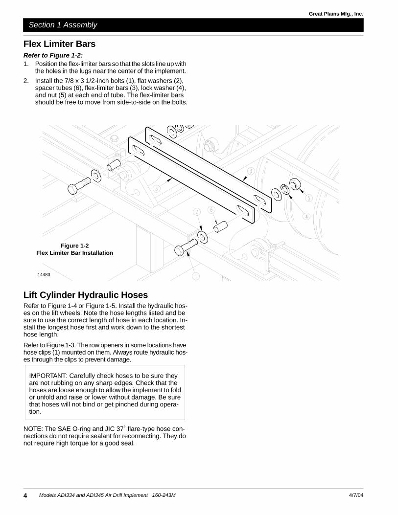
Flex Limiter BarsRefer to Figure 1-2:1. Position the flex-limiter bars so that the slots line up with
the holes in the lugs near the center of the implement.
2. Install the 7/8 x 3 1/2-inch bolts (1), flat washers (2), spacer tubes (6), flex-limiter bars (3), lock washer (4), and nut (5) at each end of tube. The flex-limiter bars should be free to move from side-to-side on the bolts.
Figure 1-2Flex Limiter Bar Installation
14483
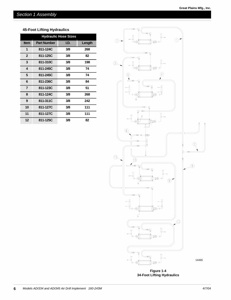
Lift Cylinder Hydraulic HosesRefer to Figure 1-4 or Figure 1-5. Install the hydraulic hos-es on the lift wheels. Note the hose lengths listed and be sure to use the correct length of hose in each location. In-stall the longest hose first and work down to the shortest hose length.
Refer to Figure 1-3. The row openers in some locations have hose clips (1) mounted on them. Always route hydraulic hos-es through the clips to prevent damage.
IMPORTANT: Carefully check hoses to be sure they are not rubbing on any sharp edges. Check that the hoses are loose enough to allow the implement to fold or unfold and raise or lower without damage. Be sure that hoses will not bind or get pinched during opera-tion.
NOTE: The SAE O-ring and JIC 37˚ flare-type hose con-nections do not require sealant for reconnecting. They do not require high torque for a good seal.

5
Section 1 Assembly
4/7/04 Models ADI334 and ADI345 Air Drill Implement 160-243M
Great Plains Mfg., Inc.
14464
34-Foot Lifting Hydraulics
Hydraulic Hose Sizes
Item Part Number I.D. Length
1 811-235C 3/8 222
2 811-237C 3/8 174
3 811-245C 3/8 74
4 811-245C 3/8 74
5 811-236C 3/8 84
6 811-123C 3/8 51
7 811-237C 3/8 174
8 811-235C 3/8 222
9 811-127C 3/8 111
10 811-127C 3/8 111
6
Section 1 Assembly
Models ADI334 and ADI345 Air Drill Implement 160-243M 4/7/04
Great Plains Mfg., Inc.
Figure 1-434-Foot Lifting Hydraulics
14465
45-Foot Lifting Hydraulics
Hydraulic Hose Sizes
Item Part Number I.D. Length
1 811-124C 3/8 268
2 811-125C 3/8 82
3 811-310C 3/8 198
4 811-245C 3/8 74
5 811-245C 3/8 74
6 811-236C 3/8 84
7 811-123C 3/8 51
8 811-124C 3/8 268
9 811-311C 3/8 242
10 811-127C 3/8 111
11 811-127C 3/8 111
12 811-125C 3/8 82

7
Section 1 Assembly
4/7/04 Models ADI334 and ADI345 Air Drill Implement 160-243M
Great Plains Mfg., Inc.
Figure 1-545-Foot Lifting Hydraulics
14478
45-Foot Folding Hydraulics
Hydraulic Hose Sizes
Item Part Number I.D. Length
1 811-095C 3/8 158
2 811-095C 3/8 158
3 811-118C 3/8 41
4 811-094C 3/8 176
5 811-094C 3/8 176
6 811-118C 3/8 41
7 811-096C 3/8 108
8 811-096C 3/8 108
9 811-117C 3/8 90
10 811-096C 3/8 108
11 811-093C 3/8 47
Figure 1-734-Foot Folding Hydraulics
Fold Cylinders
! DANGER!The folding cylinders must be bled free of air before attempting
to fold implement. Otherwise severe damage and bodily injury may result.
Position fold cylinders with base end toward center of the drill and the rod end toward wings. Pin the base end to the fold cylinder lug. Secure the pin with the provided clip. Leave rod end unhooked until after air is bled from fold cir-

8
Section 1 Assembly
Models ADI334 and ADI345 Air Drill Implement 160-243M 4/7/04
Great Plains Mfg., Inc.
34-Foot Folding Hydraulics
Hydraulic Hose Sizes
Item Part Number I.D. Length
1 811-240C 3/8 75
2 811-240C 3/8 75
3 811-241C 3/8 21
4 811-241C 3/8 21
5 811-239C 3/8 75
6 811-239C 3/8 75Figure 1-645-Foot Folding Hydraulics
14479
cuit.
Install hydraulic hoses. Refer to Figure 1-6 or Figure 1-7. Note the hose lengths and be sure to use the correct length hose in each location. Start with the longest hose and work to the shortest.
When installing, route hoses through the hose clips on the
openers. See Figure 1-3. Be sure hoses are not twisted and will not get pinched when the implement is raised, low-ered, folded or unfolded. Do not let the hoses rub on sharp edges, and be sure there is enough slack for down-flex.
NOTE: The SAE O-ring and JIC 37˚ flare-type hose con-nections do not require sealant for reconnecting. They do

9
Section 2 Setup
4/7/04 Models ADI334 and ADI345 Air Drill Implement 160-243M
Great Plains Mfg., Inc.
Section 2 Setup
This section covers dealer requirements for implement setup, including hitching the cart to the implement, bleed-ing air from the hydraulics, leveling the frame, and install-ing seed towers and hoses.
Hitching Cart to Implement
! DANGER!You may be severely injured or killed by being crushed between the cart and the implement. Do not stand or place any part of your body between the cart and implement while hooking up the air drill.
Refer to Figure 2-1.
1. With cart links tied up, slowly back cart toward the center of the implement.
2. When cart links (1) are aligned with the lower hitch plates on the cart (2), drive link pins (3) in place. Se-cure with roll pins.
Refer to Figure 2-2.
3. Make sure the cart sling (1) is connected to the cylin-der lift arm (2), then align the top hole with the support plates (3) on the back of the cart frame.
4. Install the cart sling pin (4) and secure it with the 1/4 x 2-inch cotter pins (5). Be sure cotter pins are spread.
Figure 2-1Hitching Cart to Implement
Figure 2-2Hose Routing and Sling Installation
5. Connect the primary seed hoses to the cart meter box. Connect the hoses left-to-right in the same order
14461
16547

10
Section 2 Setup
Models ADI334 and ADI345 Air Drill Implement 160-243M 4/7/04
Great Plains Mfg., Inc.
towers are installed on the implement. Route the hos-es above the cart-axle tube. Allow only enough slack for implement to be fully raised and lowered without binding. Use cable ties to secure hoses in a safe loca-tion. Secure hoses to metering-box-outlet tubes using 2 1/2-inch band clamps and tighten securely. Be sure outer clamps do not interfere with meter-box latches. Refer to Figure 2-3.
Figure 2-3Clamp Positioning
! WARNING!Escaping fluid under pressure can have sufficient pressure to penetrate the skin causing serious injury. Avoid the hazard by relieving pressure before disconnecting hydraulic lines. Use a piece of paper or cardboard, NOT BODY PARTS, to check for leaks. Wear protective gloves and safety glasses or goggles when working with hydraulic systems. If an accident occurs, see a doctor immediately. Any fluid injected into the skin must be surgically removed within a few hours or gangrene will result.
Connect hydraulic hoses to rear of cart. Refer to Figure 2-4. Working from left to right, connect hoses in the following order.
a. Connect fold hoses to outlets on the far right (out-lets A and B).
b. Connect lift hoses to the next set of outlets (out-lets C and D).
Figure 2-4Hydraulic Hose Connections
NOTE: The SAE O-ring and JIC 37˚ flare-type hose con-nections do not require sealant for reconnecting. They do not require high torque for a good seal.
6. Plug the lead from the electrical harness on the imple-ment into the cart.
7. When all connections have been made, carefully check all lines to make sure none will be damaged when the implement is operated. Re-route the lines or use cable ties to keep them in a safe place. Check warning lights for correct operation.
Bleeding the Lift HydraulicsThe implement lift system is equipped with rephasing hy-draulic cylinders that require a special procedure for bleed-ing air from the circuit. Read and follow the procedure carefully. The rephasing cylinders will not function properly with air in the circuit.
! WARNING!You may be severely injured or killed by being crushed by a fall-ing implement. Always have the frame sufficiently blocked up when working on implement.
! WARNING!Escaping fluid under pressure can have sufficient pressure to penetrate the skin causing serious injury. Avoid the hazard by relieving pressure before disconnecting hydraulic lines. Use a piece of paper or cardboard, NOT BODY PARTS, to check for leaks. Wear protective gloves and safety glasses or goggles when working with hydraulic systems. If an accident occurs, see a doctor immediately. Any fluid injected into the skin must be surgically removed within a few hours or gangrene will result.
1. Check the hydraulic fluid level in the tractor reservoir and fill to the proper level. Add fluid to the system as needed while cycling new cylinders. About 5 gallons of oil will be used to fill new cylinders. A low oil level may draw air into the system, causing jerky or uneven cylinder movement.
2. Jack up and support the front member of each frame section at a point close to each gauge wheel.
3. With the frame blocked and supported, unpin the rod end of the gauge-wheel cylinders. Pivot the cylinders up. Wire or otherwise safely support the rod-end port higher than the base-end port.
14467
17189
IMPORTANT: The cylinders located directly behind the cart will not pivot upward for bleeding. Unpin and remove these cylinders from the implement, then support rod-end port higher than the base-end port. Refer to Figure 2-5.

11
Section 2 Setup
4/7/04 Models ADI334 and ADI345 Air Drill Implement 160-243M
Great Plains Mfg., Inc.
4. With the tractor engine at an idle speed, engage the remote lever for the lifting circuit. When the outside cylinders on both sides of the implement have com-pletely extended, hold the remote lever on for one minute.
5. Retract the cylinder rods. Extend the rods again and hold the remote lever on for one more minute. Repeat this step two more times to completely bleed the sys-tem.
6. Repin cylinders.
7. Recheck the tractor reservoir and fill to the proper level.
Bleeding the Folding Hydraulics
! WARNING!Escaping fluid under pressure can have sufficient pressure to penetrate the skin causing serious injury. Avoid the hazard by relieving pressure before disconnecting hydraulic lines. Use a piece of paper or cardboard, NOT BODY PARTS, to check for leaks. Wear protective gloves and safety glasses or goggles when working with hydraulic systems. If an accident occurs, see a doctor immediately. Any fluid injected into the skin must be surgically removed within a few hours or gangrene will result.
1. Check the hydraulic fluid in the tractor reservoir and fill to the proper level. Add fluid to the system as needed. A low oil level may draw air back into the system, caus-ing jerky or uneven cylinder movement.
Figure 2-5Center Hydraulic Cylinders
14447
2. Unpin the rod end of the fold cylinders. See Figure 2-6. Wire or otherwise safely support the cylinders so when the rod is fully extended it does not contact any-thing.
3. Cycle the cylinders completely in and out at least three times to purge the air from the fold system.
NOTE: On the 45-foot implement, if the fold cylinders on one side of the drill will not move after the other side has completely extended or retracted, release the remote le-ver momentarily, reverse the lever, then try again.
4. Fully extend the cylinders and repin the rod ends.
! CAUTION!Do not fold implement unless gauge-wheel transport locks are installed.
5. Repin cylinders.
6. Recheck the tractor reservoir and fill to the proper level.
Figure 2-6Bleeding Fold Cylinders
14446
12
Section 2 Setup
Models ADI334 and ADI345 Air Drill Implement 160-243M 4/7/04
Great Plains Mfg., Inc.
Leveling Frame Side-to-Side45-Foot DrillSince the dual gauge wheels on frame sections three and four are not adjustable, make all adjustments with these as a reference.
! WARNING!You may be severely injured or killed by being crushed from a falling implement. Always have the frame sufficiently blocked up when working on implement.
1. Check that the lift circuit is free of air and full of oil. Re-fer to Bleeding the Hydraulics, page 10.
2. Hydraulically lower the entire implement frame. Fully retract all gauge-wheel cylinders. Block up or otherwise safely support the implement frame.
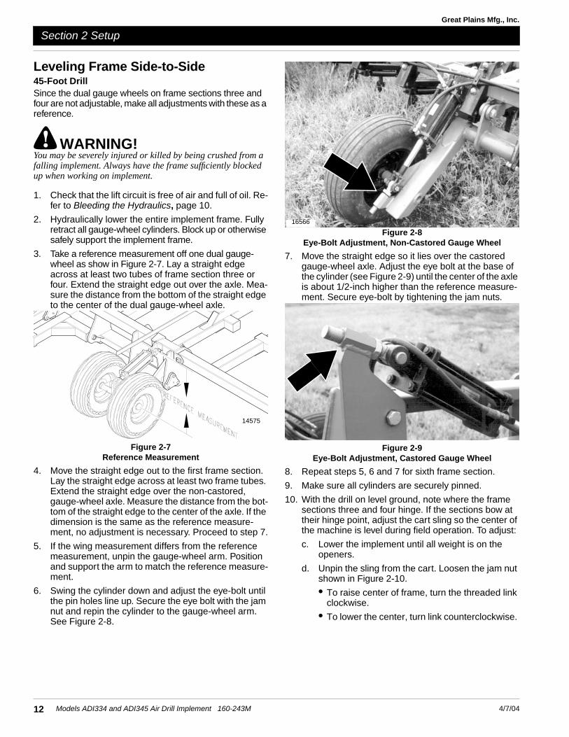
3. Take a reference measurement off one dual gauge-wheel as show in Figure 2-7. Lay a straight edge across at least two tubes of frame section three or four. Extend the straight edge out over the axle. Mea-sure the distance from the bottom of the straight edge to the center of the dual gauge-wheel axle.
Figure 2-7Reference Measurement
4. Move the straight edge out to the first frame section. Lay the straight edge across at least two frame tubes. Extend the straight edge over the non-castored, gauge-wheel axle. Measure the distance from the bot-tom of the straight edge to the center of the axle. If the dimension is the same as the reference measure-ment, no adjustment is necessary. Proceed to step 7.
5. If the wing measurement differs from the reference measurement, unpin the gauge-wheel arm. Position and support the arm to match the reference measure-ment.
6. Swing the cylinder down and adjust the eye-bolt until the pin holes line up. Secure the eye bolt with the jam nut and repin the cylinder to the gauge-wheel arm. See Figure 2-8.
Figure 2-8Eye-Bolt Adjustment, Non-Castored Gauge Wheel
7. Move the straight edge so it lies over the castored gauge-wheel axle. Adjust the eye bolt at the base of the cylinder (see Figure 2-9) until the center of the axle is about 1/2-inch higher than the reference measure-ment. Secure eye-bolt by tightening the jam nuts.
Figure 2-9Eye-Bolt Adjustment, Castored Gauge Wheel
8. Repeat steps 5, 6 and 7 for sixth frame section.
9. Make sure all cylinders are securely pinned.
10. With the drill on level ground, note where the frame sections three and four hinge. If the sections bow at their hinge point, adjust the cart sling so the center of the machine is level during field operation. To adjust:
c. Lower the implement until all weight is on the openers.
d. Unpin the sling from the cart. Loosen the jam nut shown in Figure 2-10.
• To raise center of frame, turn the threaded link clockwise.
• To lower the center, turn link counterclockwise.
14575
16566

13
Section 2 Setup
4/7/04 Models ADI334 and ADI345 Air Drill Implement 160-243M
Great Plains Mfg., Inc.
e. Tighten jam nut and repin sling to cart. Recheck levelness and re-adjust as necessary.
Figure 2-10Cart Sling
34-Foot DrillSince the dual gauge wheels on frame sections three and four are not adjustable, make all adjustments with these as a reference.
! WARNING!You may be severely injured or killed by being crushed by a fall-ing implement. Always have the frame sufficiently blocked up when working on implement.
1. Check that the lift circuit is free of air and full of oil. Re-fer to Bleeding the Hydraulics, page 10.
2. Hydraulically lower the entire implement frame. Fully retract all gauge-wheel cylinders. Block up or otherwise support the implement frame.
3. Take a reference measurement from the top of the im-plement frame to the center of one dual gauge-wheel axle as show in Figure 2-7, page 12. Lay a straight edge across at least two tubes of frame section three
16569
or four. Extend the straight edge out over the axle. Measure the distance from the bottom of the straight edge to the center of the axle.
4. Move the straight edge out to the first frame section. Lay the straight edge across at least two frame tubes. Extend the straight edge out over the non-castored, gauge-wheel axle. Measure the distance from the bot-tom of the straight edge to the center of the axle. If the dimension is the same as the reference measure-ment, no adjustment is necessary. Proceed to step 7.
5. If the wing measurement differs from the reference measurement, unpin the gauge-wheel arm. Position and support the arm to match the reference measure-ment.
6. Swing the cylinder down and adjust the eye-bolt (Fig-ure 2-8) until the pin holes line up. Secure the eye bolt with the jam nut and repin the cylinder to the gauge-wheel arm.
7. Repeat steps 5 and 6 for implement section four.
8. Make sure that all cylinders are securely pinned.
9. With the drill on level ground, note where the frame sections three and four hinge. If the sections bow at their hinge point, adjust the cart sling so the center of the machine is level during field operation. To adjust:
a. Lower the implement until all weight is resting on the openers.
b. Unpin the sling from the cart.
c. Loosen the jam nut shown in Figure 2-10, page 13.
• To raise the center of the frame, turn the thread-ed link clockwise.
• To lower the center, turn the threaded link coun-terclockwise.
d. When satisfied with adjustment, tighten jam nut and repin sling to cart. Recheck levelness and re-adjust as necessary.
14
Section 2 Setup
Models ADI334 and ADI345 Air Drill Implement 160-243M 4/7/04
Great Plains Mfg., Inc.
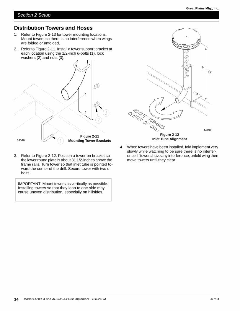
Distribution Towers and Hoses1. Refer to Figure 2-13 for tower mounting locations.
Mount towers so there is no interference when wings are folded or unfolded.
2. Refer to Figure 2-11. Install a tower support bracket at each location using the 1/2-inch u-bolts (1), lock washers (2) and nuts (3).
3. Refer to Figure 2-12. Position a tower on bracket so the lower round plate is about 31 1/2-inches above the frame rails. Turn tower so that inlet tube is pointed to-ward the center of the drill. Secure tower with two u-bolts.
14546Figure 2-11
Mounting Tower Brackets
IMPORTANT: Mount towers as vertically as possible. Installing towers so that they lean to one side may cause uneven distribution, especially on hillsides.
4. When towers have been installed, fold implement very slowly while watching to be sure there is no interfer-ence. If towers have any interference, unfold wing then move towers until they clear.
Figure 2-12Inlet Tube Alignment
14499

15
Section 2 Setup
4/7/04 Models ADI334 and ADI345 Air Drill Implement 160-243M
Great Plains Mfg., Inc.
Figure 2-13Tower Mounting Locations
14486
45-Foot Drill
34-Foot Drill

16
Section 2 Setup
Models ADI334 and ADI345 Air Drill Implement 160-243M 4/7/04
Great Plains Mfg., Inc.
Primary Distribution Hoses1. Start with the third, or center tower. Route hose as
shown in Figure 2-16 and Figure 2-17. Slide clamp over end of hose, then slide hose at least two inches onto tower inlet.
2. Allow enough hose so that implement raising, lower-ing, folding and unfolding will not pinch or bind hose.
3. Using a hacksaw, cut hose so that it will slide onto meter outlets up to end of flare.
4. Slide clamp over hose end, then slide hose onto meter outlet. Install clamp so that it will not interfere with oth-er hoses, clamps or meter-door latches. Figure 2-14.
5. Repeat this procedure on towers two and four. Cut these two the same length but longer than the center hose.
6. Repeat the same procedures for towers one and five. These two hoses should also be the same length, but longer than the others.
7. Secure all hoses to the frame using 24-inch cable ties. Make sure hoses will not be damaged during drill op-eration.
Secondary HosesSecondary seed hose is one inch in diameter and comes in 100-foot rolls. Cut secondary hoses to connect each opener to a distribution tower. Refer to the appropriate hose routing illustration for the correct hose routings.
See Figure 2-15.
1. Start with tower 1 (far left tower). Loosen but do not re-move bolts holding tower halves together.
Figure 2-14Clamp Positioning
14467
IMPORTANT: Do not cut hose until routed over imple-ment.
2. Insert hose into port. Push hose into port until seated against the stop.
3. Keeping your implement row spacing in mind, refer to-Figure 2-16 or Figure 2-17 to find which opener to con-nect the hose.
! DANGER!To avoid serious injury or death from crushing, make sure trans-port locks are in place, the drill is sufficiently blocked up, and the tractor is shut off with the key removed before attempting to route hoses to openers.
4. Route hose over implement frame as shown in Figure 2-16 or Figure 2-17. Route hoses to prevent rubbing on sharp edges or damage when the implement is raised, lowered, folded or unfolded. Allow enough hose slack for implement folding and down-flex.
5. When you are satisfied you have the proper hose length, cut hose.
Figure 2-15Tower Assembly
14449

17
Section 2 Setup
4/7/04 Models ADI334 and ADI345 Air Drill Implement 160-243M
Great Plains Mfg., Inc.
34-Foot Drill, 10-Inch Row Spacing 14533
Figure 2-16Seed Hose Routings
34-Foot Drill, 7-Inch Row Spacing 14542

18
Section 2 Setup
Models ADI334 and ADI345 Air Drill Implement 160-243M 4/7/04
Great Plains Mfg., Inc.
34-Foot Drill, 12-Inch Row Spacing 14534
45-Foot Drill, 7-Inch Row Spacing14543
Figure 2-17Seed Hose Routings (con’t.)
19
Section 2 Setup
4/7/04 Models ADI334 and ADI345 Air Drill Implement 160-243M
Great Plains Mfg., Inc.
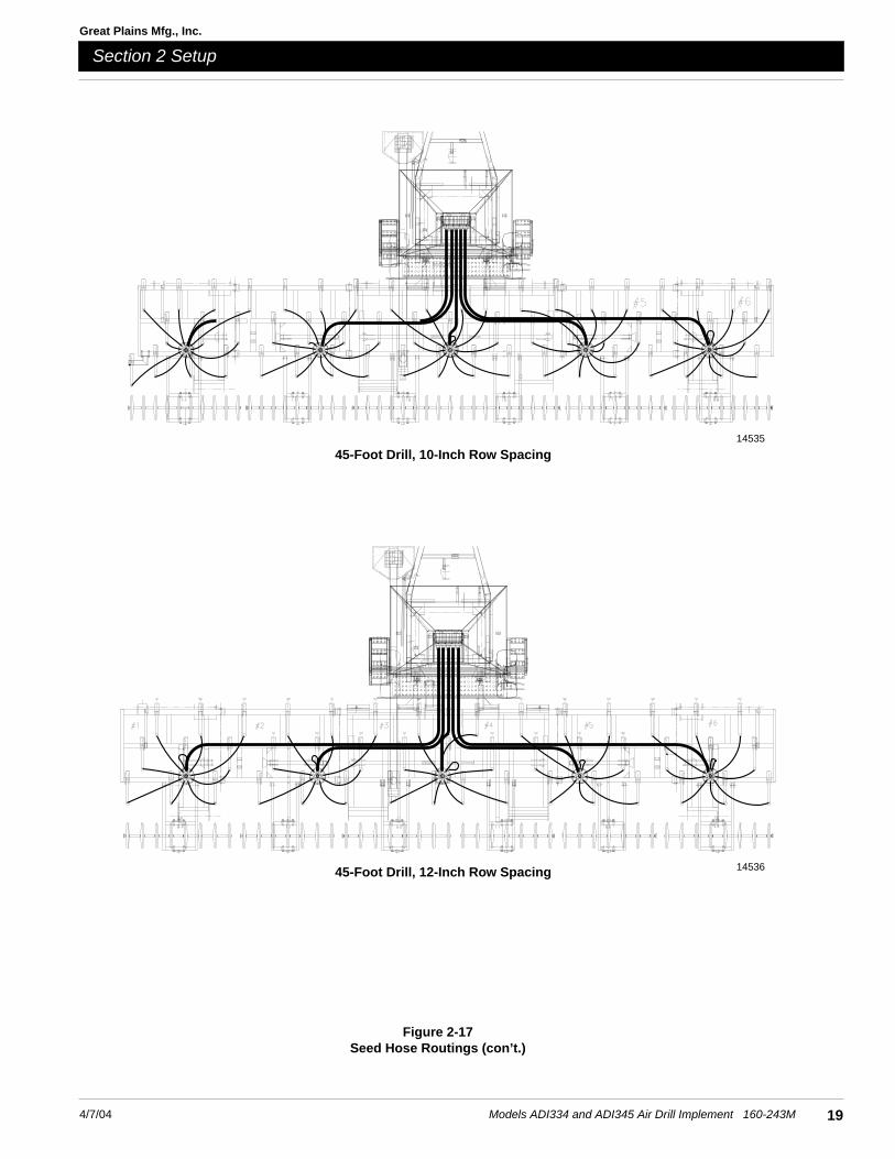
14535
45-Foot Drill, 10-Inch Row Spacing
14536
Figure 2-17Seed Hose Routings (con’t.)
45-Foot Drill, 12-Inch Row Spacing

20
Section 2 Setup
Models ADI334 and ADI345 Air Drill Implement 160-243M 4/7/04
Great Plains Mfg., Inc.
Refer to Figure 2-18:8. Attach the end of the hose to opener.
Slide clamp over the end of the hose six inches. Put the end of the hose in the seed tube six inches. Hook the clamp ends in the holes at the top of the seed tube.
Figure 2-18Hose Installation On Openers
14563
9. Repeat steps 1 through 8 for all one-inch hoses on each tower.
10. When all hoses are installed on a tower, tighten the bolts holding the halves together.
11. Check all hoses to be sure that they are not rubbing on sharp edges and will not be damaged when the drill is raised, lowered, folded or unfolded. Re-route if need-ed to prevent damage.
IMPORTANT: The tower bolts are equipped with ny-lock nuts and should not be over-tightened. Tighten the bolts only until the hose is held securely against being blown out.

Tire Inflation ChartTire Size Inflation PSI Tire Size Inflation PSI
7.50 x 20" 4-Ply Drill Rib 28 11L x 15" 6-Ply Rib Implement 28
9.0 x 22.5 10-Ply Highway Service 70 70 11L x 15" 12-Ply Rib Implement 52
9.0 x 24" 8-Ply Rib Implement 40 12.5L x 15" 8-Ply Rib Implement 36
9.5L x 15" 6-Ply Rib Implement 32 12.5L x 15" 10-Ply Rib Implement 44
9.5L x 15" 8-Ply Rib Implement 44 16.5L x 16.1" 10-Ply Rib Implement 36
9.5L x 15" 12-Ply Rib Implement 60 41 x 15" x 18 - 22-Ply Rib Implement 44
Torque Values Chart for Common Bolt Sizes
in-tpi1 N · m2 ft-lb3 N · m ft-lb N · m ft-lb mm x pitch4 N · m ft-lb N · m ft-lb N · m ft-lb
1/4" - 20 7.4 5.6 11 8 16 12 M 5 X 0.8 4 3 6 5 9 7
1/4" - 28 8.5 6 13 10 18 14 M 6 X 1 7 5 11 8 15 11
5/16 - 18 15 11 24 17 33 25 M 8 X 1.25 17 12 26 19 36 27
5/16" - 24 17 13 26 19 37 27 M 8 X 1 18 13 28 21 39 29
3/8" - 16 27 20 42 31 59 44 M10 X 1.5 33 24 52 39 72 53
3/8" - 24 31 22 47 35 67 49 M10 X 0.75 39 29 61 45 85 62
7/16" - 14 43 32 67 49 95 70 M12 X 1.75 58 42 91 67 125 93
7/16" - 20 49 36 75 55 105 78 M12 X 1.5 60 44 95 70 130 97
1/2" - 13 66 49 105 76 145 105 M12 X 1 90 66 105 77 145 105
1/2" - 20 75 55 115 85 165 120 M14 X 2 92 68 145 105 200 150
9/16" - 12 95 70 150 110 210 155 M14 X 1.5 99 73 155 115 215 160
9/16" - 18 105 79 165 120 235 170 M16 X 2 145 105 225 165 315 230
5/8" - 11 130 97 205 150 285 210 M16 X 1.5 155 115 240 180 335 245
5/8" - 18 150 110 230 170 325 240 M18 X 2.5 195 145 310 230 405 300
3/4" - 10 235 170 360 265 510 375 M18 X 1.5 220 165 350 260 485 355
3/4" - 16 260 190 405 295 570 420 M20 X 2.5 280 205 440 325 610 450
7/8" - 9 225 165 585 430 820 605 M20 X 1.5 310 230 650 480 900 665
7/8" - 14 250 185 640 475 905 670 M24 X 3 480 355 760 560 1050 780
1" - 8 340 250 875 645 1230 910 M24 X 2 525 390 830 610 1150 845
1" - 12 370 275 955 705 1350 995 M30 X 3.5 960 705 1510 1120 2100 1550
1-1/8" - 7 480 355 1080 795 1750 1290 M30 X 2 1060 785 1680 1240 2320 1710
1 1/8" - 12 540 395 1210 890 1960 1440 M36 X 3.5 1730 1270 2650 1950 3660 2700
1 1/4" - 7 680 500 1520 1120 2460 1820 M36 X 2 1880 1380 2960 2190 4100 3220
1 1/4" - 12 750 555 1680 1240 2730 2010
1 3/8" - 6 890 655 1990 1470 3230 2380 1 in-tpi = nominal thread dia.in inches-threads per inch
1 3/8" - 12 1010 745 2270 1670 3680 2710 2 N· m = newton-meters
1 1/2" - 6 1180 870 2640 1950 4290 3160 3 ft-lb= foot pounds
1 1/2" - 12 1330 980 2970 2190 4820 3560 4 mm x pitch = nominal thread dia. in millimeters x thread pitch
Torque tolerance + 0%, -15% of torquing values. Unless otherwise specified use torque values listed above.
21
Appendix
4/7/04 Models ADI334 and ADI345 Air Drill Implement 160-243M
Great Plains Mfg., Inc.
Appendix
5.8 8.8 10.9
Class 5.8 Class 8.8 Class 10.9
Bolt Head Identification
Bolt Size(Metric)Grade 2 Grade 5 Grade 8
Bolt Head Identification
Bolt Size(Inches)

Great Plains Manufacturing, Inc.Corporate Office: PO. Box 5060
Salina, Kansas 67402-5060 USA