Embed Size (px)
Citation preview
Predator Series LED Hideaway Strobe Light
Operating Manual and Installation Instructions

Predator Series LED Hideaway Strobe LightOperating Manual and Installation Instructions
Warnings and Notices for Users and Installers
WARNING: Take CAUTION when installing
This document must be delivered to and read by the end user and installer as it serves to provide you with the required information for proper and safe use of your LEDEQUIPPED product. Before operating this or any LEDEQUIPPED products the user and installer must read this manual all the way through. You will find important information in this manual that could prevent property damage and/or serious injury to the user and installer. LEDEQUIPPED products are intended to alert pedestrians and other operators of the presence of personnel, the operation of emergency vehicles, an emergency site, and any warning needs. It is your responsibility to make sure you can proceed safely before driving against traffic, entering an intersection, responding to a high rate of speed, or walking on or around traffic lanes.
Your LEDEQUIPPED emergency vehicle devices should be tested daily to insure the device and all its functions are operating correctly. If you experience a malfunction contact LEDEQUIPPED's Customer Service immediately for troubleshooting options, or a warranty or service claim. You must ensure sure that the projection of the visual and audible is not blocked by vehicle components (i.e.: open trunks, visors, compartment doors), vehicles, other obstructions, or people. LEDEQUIPPED's sirens and other audible devices project sound in a forward direction and should be installed in a forward direction that faces away from the occupants of the vehicle.
This is professional grade equipment and is intended for strict use by authorized personal only. It is the user's responsibility to understand and obey all laws regarding emergency warning devices. You must know and be familiar with all applicable city, sate, and federal laws and regulations prior to the use of emergency vehicle warning devices. LEDEQUIPPED assumes no liability for any loss resulting from the use of this warning device. Proper installation is vital to the performance of the warning devices and safe operation of the emergency vehicle. Since the operator is under stressful environments the equipment must be properly wired and mounted to ensure effectiveness and safety. Therefore, controllers must be properly installed and placed within convenient reach of the operator so eye contact with the roadway is never lost. The effectiveness of your LEDEQUIPPED equipment is highly dependent upon correct mounting and wiring.
Improper wiring and mounting of the warning device will reduce the output and performance of the equipment. Emergency warning devices frequently require high electrical voltages and/or currents. Properly protect and use caution around live electrical connections. Grounding or shorting of electrical connections can cause high current arcing, which can cause severe personal injury and/or serious vehicle damage, including fire. Electromagnetic interference can be caused by many electronic devices used in emergency vehicles. To ensure that this doesn't happen to you, lights bars should be mounted a minimum of 12" - 34" from the radio antenna and do not power your equipment from the same circuit or share the same grounding circuit with radio communication equipment. After installation test all the
1
vehicles equipment together to ensure everything operates free of interference. Driver and/or passenger airbags bags (SRS) will impact the way you mount your equipment. Any equipment installed in the deployment area of the airbags will damage or dislodge the airbags and sensors. This will also reduce the effectiveness of the airbags to protect the passengers and therefore these areas must be avoided. Installers must make sure that this equipment along with any parts, hardware, wiring, power supplies, and switch boxes do not interfere with the airbags, SRS wiring, or sensors. All LEDEQUIPPED equipment needs to be mounted and installed according to the vehicle manufactures instructions and securely attached to a part of the vehicle of sufficient strength to withstand the forces applied to the equipment. This device should be permanently mounted within the zones specified by the vehicle manufactures. This especially applies to equipment mounted on the exterior of the vehicle to avoid dislodging. When mounting units on the interior of the vehicle by a method other than permanent mount is discouraged as it may become too detached under aggressive driving conditions such as sudden breaking, collision, or swerving.
Important Points for Your Safety and Longevity of your Equipment
Installers are required to have a good understanding of automotive electronic, systems and procedures for proper installation.
- One should not stare directly into the LEDs as momentary blindness and/or eye damage may occur.
- One should not take any lights through a car wash. Use only water to clean the outer body/lens of your equipment. –
- One should not use a pressure washer to clean any LEDEQUIPPED products. Inspect and test your product daily to insure it operates properly and is mounted correctly.
- One should not cut wires or work on a unit while the unit is still connected to a power source.
- One should not install this product or rout any wires through or in the deployment area of the airbag. Doing so may cause serious personal injury as it will damage or reduce the effectiveness of the airbag by causing the unit to become a projectile.
Reference the owner's manual for your vehicle to find the airbag deployment area. The User/Installer assumes all responsibility to determine proper mounting location, based on providing ultimate safety to all passengers in the vehicle.
- If the product requires you to drill holes the installer must ensure that the drilling process does not damage any vehicle components or other vital parts. Check all sides of the mounting surface before beginning to drill. Make sure to deburr all drilled holes and remove any metal remnants or shards to avoid injury and wires from becoming spliced. Grommets are to be installed in all wire passage holes.
- For LEDEQUIPPED products to operate at optimum efficiency a secure and good electrical connection to the Batteries Ground Post must be made. The recommended procedure requires the unit's ground wire be connected directly to the NEGATIVE (-) battery post.
2
3
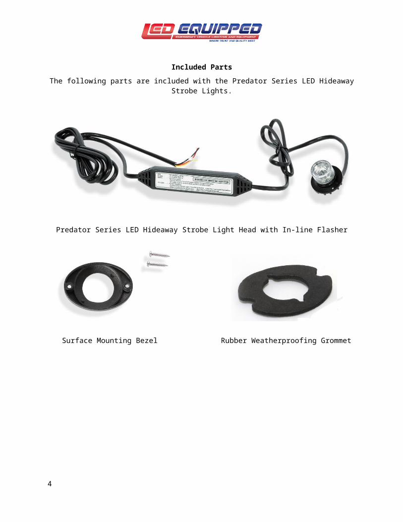
Included Parts
The following parts are included with the Predator Series LED Hideaway Strobe Lights.
Predator Series LED Hideaway Strobe Light Head with In-line Flasher
Surface Mounting Bezel Rubber Weatherproofing Grommet
4

Instructions for Wiring and Operation
Installation and Wiring
To ensure proper installation installers are required to have a good understanding of automotive electronic, systems and procedures for proper installation.
When you are drilling into the vehicle's surfaces, ensure that the area is free of any electrical wires, vehicle upholstery, fuel lines, etc. that could be damaged. All wiring passing through drilled holes should use grommets and silicone sealant to prevent wire or moisture damage when passing through compartment walls.
WARNING! Larger wires and secure or tight connections will ensure longer service life for your product. It is highly recommended that soldered connections have heat shrink used to protect the connection. Special attention should be given to the location and method of splicing wires to make electrical connections to protect these splices from lost power or connection and corrosion.
Insulation displacement connectors are not to be used. To reduce voltage drop, minimize the number of splices in the wires. The current carrying capacity of wires and fuses will be significantly reduced under high ambient temperature (e.g. under the hood).
All wires should be in accordance with the minimum wire size and other recommendations made by the manufacturer and be protected from hot surfaces and moving parts. Grommets, cable ties, looms, and other installation hardware should be used to anchor and protect all wiring. Fuses should be properly sized and located as close to the power take off points as possible to protect the wiring and device. To protect against short circuits, a fuse is included by LEDEQUIPPED for all products. Do NOT use a fuse with a higher amp rating than the initial fuse included.
5
Installing the Predator Series LED Hideaway Strobe Light
The Predator Series LED Hideaway Strobe Light is designed to be installed within your vehicle light housing or installed as a surface mounted exterior light head. The Predator Series LED Hideaway Strobe Light uses an industry standard one (1) inch mounting hole within your vehicle’s light housing for a hidden, stealth installation. Optionally, external mounting can be done using the included external mounting flange for installation anywhere on the exterior of your vehicle, including bumpers, push bars, side mirrors, quarter panels, or anywhere else where you wish to have low profile discrete lighting on the exterior of your emergency vehicle.
Installation in Vehicle Light Housing
The most common installation location for the Predator Series LED Hideaway Strobe Light is inside of your vehicle’s light housings. It is common to have multiple Predator Series LED Hideaway Strobe light heads installed in your headlight housing and your tail light housing and configured to flash in either a simultaneous or alternating flash pattern. If you have selected a light head with multiple colors, both colors can be used to flash together, or separately, increasing the perceptibility of your vehicle in all emergency situations.
Installation in a vehicle light housing in many instances requires the removal of the existing light housing from the vehicle. It is strongly recommended that you remove the vehicle light housing in which you are installing your Predator Series LED Hideaway Strobe light heads, as installation will require that you drill a one (1) inch diameter hole in the housing. Removal of the vehicle light housing will assist in determining the ideal placement and location of the light head inside of the light housing, and will assist in assuring that the desired mounting location is free of impacting or damaging any existing wiring or functionality of the required exterior vehicle lighting (headlights, tail lights, reverse lights, etc.). Please note that during the installation of your Predator LED Hideaway Strobe Lights, it is essential that the installer take the necessary precautions to not impede the proper operation of your vehicle’s exterior light operation. Improper installation location can result in having a significant negative effect on your vehicle’s exterior light operation, and is at the sole and exclusive responsibility of the installer. Please refer to your vehicle manufacturer’s instructions for instructions on the proper removal and reinstallation of vehicle light housings. It should be noted that removal of headlight housings may result in the need to adjust your headlights to properly aim your reinstalled headlight housing. This procedure should be done according to vehicle manufacturer’s instructions.
Once an appropriate installation location has been identified within your vehicle light housing, use a one (1) inch diameter hole saw to drill the appropriate sized opening for mounting the Predator LED Hideaway Strobe light head. Using the supplied weatherproofing grommet, place the grommet over the top of the Predator LED Hideaway Strobe light head, so that when installed, it is seated between the light head and your vehicle’s light housing. This is designed to reduce the possibility of moisture entering your vehicle light housing after installation. Improper installation of the Predator LED Hideaway Strobe light head without the use of the supplied weatherproofing grommet can lead to moisture or condensation build up inside your vehicle light housing and damage the operation of your
6
vehicle exterior lights.
With the one (1) inch diameter opening has been made in your vehicle light housing, and with the supplied weatherproofing grommet installed over the light head, insert your Predator LED Hideaway Strobe light head into your vehicle light housing. Using the supplied hardware, secure the Predator LED Hideaway Strobe light head to your vehicle light housing through the installation mounting holes on the light head (see Figure 1 below). It is strongly recommended that mounting holes are predrilled within your vehicle light housing before installation of the light head using the supplied hardware. This will reduce the possibility of damaging your vehicle light housing. Optionally, you may choose to use some weatherproofing silicone to further seal the hardware mounting hole that is used to securely fasten your Predator LED Hideaway Strobe light head to your vehicle light housing. This will further prevent moisture intrusion into your vehicle light housing, but should be used at the discretion of the installer.
Reinstall your vehicle light housing and securely route the Predator LED Hideaway Strobe Light wiring to the desired location in your vehicle. Repeat this process for each Predator LED Hideaway Strobe light head and then processed to the wiring instructions included below.
7

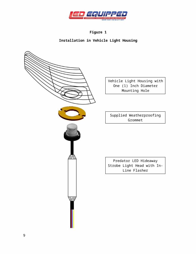
Supplied Weatherproofing Grommet
Figure 1
Installation in Vehicle Light Housing
8
Vehicle Light Housing with One (1) Inch Diameter Mounting Hole
Predator LED Hideaway Strobe Light Head with In-Line Flasher
Surface Mount Installation
The Predator LED Hideaway Strobe Light can also be surface mounted externally on your vehicle using the exterior surface mounting bezel for a clean and discrete installation. Once it has been determined where the Predator LED Hideaway Strobe light head will be located, it is necessary to create an opening through which you are able to fit the in-line flasher module for installation. Although a one (1) inch mounting hole is not required for a surface mount installation, an opening in the mounting surface must be made large enough through which to route the in-line flasher module and wiring for your Predator LED Hideaway Strobe light head.
Once a desired installation location has been identified, and an appropriately sized opening has been made through which to install the in-line flasher module and light head wiring can be installed, you are ready to prepare the Predator LED Hideaway Strobe light head for installation. Before installation, using the supplied weatherproofing grommet, thread the in-line flasher module and light head wiring through the weatherproofing grommet, so that when installed, it is seated between the light head and your desired mounting location. This is designed to reduce the possibility of moisture penetrating the opening created for mounting the Predator LED Hideaway Strobe Light after installation. Improper installation of the Predator LED Hideaway Strobe light head without the use of the supplied weatherproofing grommet can lead to unwanted moisture penetration through the mounting opening.
With the opening that has been made in the mounting surface for the in-line flasher module and light head wiring, and with the supplied weatherproofing grommet installed over the in-line flasher module and light head wiring, place the supplied exterior surface mounting bezel over the Predator LED Hideaway Strobe light head and run the wiring through the mounting hole. Using the supplied hardware, secure the Predator LED Hideaway Strobe light head to your vehicle through the installation mounting holes on the light head (see Figure 2 below). It is strongly recommended that mounting holes are predrilled before installation of the light head using the supplied hardware. This will reduce the possibility of damaging your mounting surface. Optionally, you may choose to use some weatherproofing silicone to further seal the hardware mounting hole that is used to securely fasten your Predator LED Hideaway Strobe light head to your mounting surface. This will prevent moisture intrusion though the mounting surface, but should be used at the discretion of the installer.
Once your Predator LED Hideaway Strobe Light has been securely attached to the desired mounting surface, route the Predator LED Hideaway Strobe Light wiring to the desired location in your vehicle. Repeat this process for each Predator LED Hideaway Strobe light head and then processed to the wiring instructions included below.
9
Figure 2
Surface Mount Installation
10
Exterior Surface Mounting Bezel
Predator LED Hideaway Strobe Light
Predator LED Hideaway Strobe Light In-Line Flasher and Wiring
Supplied Weatherproofing Grommet
Wiring the Predator Series LED Hideaway Strobe Light
The Predator Series LED Hideaway Strobe Light is fully encapsulated, weather and vibration resistant, and comes configured with four (4) wires for ease of installation. Each Predator Series LED Hideaway unit is easily configured to allow for multiple light heads to be flashing simultaneously or alternating with the included twenty-one (21) preconfigured flash patterns. The Predator Series LED Hideaway Strobe Lights have been designed for ease of installation and adaptation for use with up to eight (8) additional Predator Series LED Hideaway Strobe Lights with limited additional wiring. This design allows for installers to create seamless integration of these units for your specific application.
All of the Predator Series LED Hideaway Strobe Lights can be hard wired to an external switch according to the wiring specifications included in Figure 3 below. Please note that the 12v + (Positive/Red Wires) and 12v – (Negative/Black Wires) wiring connections must be made to an appropriate 12v power source and ground in order for your Predator Series LED Hideaway Strobe Lights to function properly.
All wiring connections should be secured using appropriate automotive connectors or through the use of soldered connections. All connections should be protected by using heat shrink wire wrap in order to protect the connection. Special attention should be given to the location and method of splicing wires to make electrical connections to protect these splices from lost power or connection and corrosion.
Figure 3
Predator Series LED Hideaway Strobe Lights
Wire Color Function
Red 12v + (Positive)
Black 12v – (Negative)
Yellow Flash Pattern Selection
Blue Synchronization
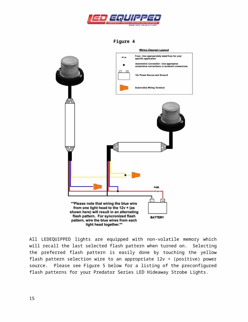
Please refer to Figure 4 below for a visual representation of how to wire the Predator LED Hideaway Strobe light heads in an alternating pattern configuration.
11
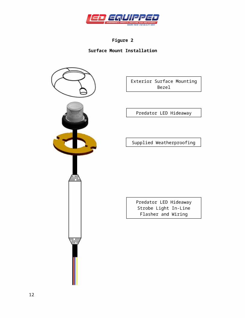
Figure 4
All LEDEQUIPPED lights are equipped with non-volatile memory which will recall the last selected flash pattern when turned on. Selecting the preferred flash pattern is easily done by touching the yellow flash pattern selection wire to an appropriate 12v + (positive) power source. Please see Figure 5 below for a listing of the preconfigured flash patterns for your Predator Series LED Hideaway Strobe Lights.
12

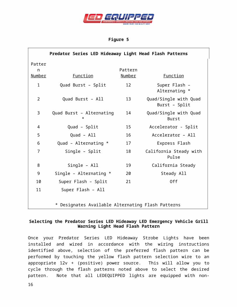
Figure 5
Predator Series LED Hideaway Light Head Flash Patterns
PatternNumber Function
PatternNumber Function
1 Quad Burst – Split 12 Super Flash – Alternating *
2 Quad Burst – All 13 Quad/Single with Quad Burst – Split
3 Quad Burst – Alternating * 14 Quad/Single with Quad Burst
4 Quad – Split 15 Accelerator - Split
5 Quad – All 16 Accelerator – All
6 Quad – Alternating * 17 Express Flash
7 Single – Split 18 California Steady with Pulse
8 Single – All 19 California Steady
9 Single – Alternating * 20 Steady All
10 Super Flash – Split 21 Off
11 Super Flash – All
* Designates Available Alternating Flash Patterns
Selecting the Predator Series LED Hideaway LED Emergency Vehicle Grill Warning Light Head Flash Pattern
Once your Predator Series LED Hideaway Strobe Lights have been installed and wired in accordance with the wiring instructions identified above, selection of the preferred flash pattern can be performed by touching the yellow flash pattern selection wire to an appropriate 12v + (positive) power source. This will allow you to cycle through the flash patterns noted above to select the desired pattern. Note that all LEDEQUIPPED lights are equipped with non-volatile memory which will recall the last selected flash pattern when turned on.
Single Flash Pattern
Configuring the Predator Series LED Hideaway Strobe light heads to operate on a single flash pattern requires that each Predator Series LED Hideaway Strobe light head be properly connected to an appropriate 12v + (positive) and 12v – (negative) power source. In addition, each light head can be synchronized to flash using the same selected pattern on each additional light head by connecting the blue wires on each Predator Series LED light head. This installation method will result in a synchronization of all installed light heads.
13

To configure all Predator Series LED Hideaway series light heads to operate using a single preinstalled flash pattern, connect the 12v + (positive - red wires), 12v – (negative - black wires), synchronization (blue wires), and pattern selection (yellow wires) together from each light head. Connect the light heads to an appropriate 12v + (positive) power source to power on the light heads. When powered on for the first time, it is necessary to synchronize the light heads by applying the pattern selection wire (yellow wire) to an appropriate 12v + (positive) power source for five (5) seconds. Releasing the pattern selection wire will result in resetting the pattern selection to the Single Flash flash pattern. Once each light head is at the Single Flash flash pattern, using the bundled yellow flash pattern selection wires will allow you to cycle through the available flash patterns by touching the pattern selection wires to an appropriate 12v + (positive) power source momentarily. Once the desired pattern is selected, cap off the pattern selection wires to ensure that they do not inadvertently come into contact with a 12v + (positive) power source and change pattern selection.
All Predator Series LED Hideaway Strobe light heads come with a non-volatile memory which will automatically recall the last pattern selected when powered on.
Alternating Flash Pattern
Predator Series LED Hideaway Strobe light heads come preinstalled to allow for the configuration of alternating flash patterns. Please note that alternating flash pattern selection utilizes independent flash pattern configurations, and therefore only of a subset of the regular flash patterns, specifically designed for alternating light head installations, is available.
Alternating flash patterns on your Predator LED Hideaway Strobe light heads are easily set up by first making sure that each Predator Series LED Hideaway series light head is properly connected to an appropriate 12v + (positive) and 12v – (negative) power source. Each light head that will be synchronized together, in a group in the alternating flash pattern, should be bundled together using the synchronization (blue) wires on each Predator LED Hideaway Strobe light head, and appropriately divided into two alternating groups. All light heads should be programmed to the same pattern to begin. Connect one bundled group of light heads in the alternating pattern using the bundled synchronization (blue) wires permanently to an appropriate 12v + (positive) power source. Connecting one group of light heads to an appropriate 12v + (positive) power source using the synchronization (blue) wires will configure the alternating patterns.
Once each group of light heads has been appropriately wired together (12v + [red wire], 12v – [black wire], synchronization [blue wire], and flash pattern [yellow wire]), contact the group of bundled yellow wires from all light heads to a 12v + (positive) power source momentarily. Each time the group of bundled yellow wires is momentarily connected to a 12v + (positive) power source will advance to the next available flash pattern. Please note that only a subset of the preinstalled flash patterns has been designated for use in an alternating pattern installation.
All Predator Series LED Hideaway series light heads come with a non-volatile memory which will automatically recall the last pattern selected when powered on.
14
Predator Series LED Hideaway Strobe Light Head Optional Accessories
Combat Controller
Product Number: A-1516Combat Mini Controller
Product Number: A-1515
Black Falcon Siren and Control UnitProduct Number: A-1237 (100w) and
A-1368 (200w)
Pelican Siren and Control UnitProduct Number: A-1108 (100w) and
A-1109 (200w)
15
At LEDEQUIPPED, we know that you need affordable lighting for your police, EMS, fire, construction, or towing vehicles and that safety and reliability are important to you. That’s why all of our LED products feature powerful up do date Generation LED lighting, perfect for your police, fire, construction, or EMS vehicle. LEDEQUIPPED focuses on a mission to carry out business ethically and with integrity, provide powerful products of the highest quality, maintain excellent and affordable prices, and to establish an unparalleled customer service relationship beginning with establishing trust with our customers. As a provider of emergency vehicle lighting, we value the honesty, professionalism, and expertise present within our customer base
For any questions regarding our products, contact us by calling us at +1 800-846-3940 or email us at [email protected].
© 2019 LEDEQUIPPED. All Rights Reserved.