Embed Size (px)
Citation preview
LA-13178
Advanced Recovery and Integrated
Extraction System (ARIES)
LosN A T I O N A L L A B O R A T O R Y
AlamosLos Alamos National Laboratory is operated by the University of Californiafor the United States Department of Energy under contract W-7405-ENG-36.
Preconceptual Design Report
Edited by Linda K. Wood, CIC-1
An Affirmative Action/Equal Opportunity Employer
This report was prepared as an account of work sponsored by an agency of the United StatesGovernment. Neither The Regents of the University of California, the United States Governmentnor any agency thereof, nor any of their employees, makes any warranty, express or implied, orassumes any legal liability or responsibility for the accuracy, completeness, or usefulness of anyinformation, apparatus, product, or process disclosed, or represents that its use would not infringeprivately owned rights. Reference herein to any specific commercial product, process, or service bytrade name, trademark, manufacturer, or otherwise, does not necessarily constitute or imply itsendorsement, recommendation, or favoring by The Regents of the University of California, theUnited States Government, or any agency thereof. The views and opinions of authors expressedherein do not necessarily state or reflect those of The Regents of the University of California, theUnited States Government, or any agency thereof. The Los Alamos National Laboratory stronglysupports academic freedom and a researcher's right to publish; therefore, the Laboratory as aninstitution does not endorse the viewpoint of a publication or guarantee its technical correctness.
Advanced Recovery and IntegratedExtraction System (ARIES)
LA-13178
Timothy O. NelsonM. C. BronsonD. K. DennisonBart FlammDewey RavenscroftCarlos ColmenaresJohn HuangTerry CremersThomas SampsonLawrence BroniszH. E. MartinezPaul SaykaDonald PomplunRalph Hinde
UC-700 and UC-721Issued: September 1996
LosN A T I O N A L L A B O R A T O R Y
AlamosLos Alamos, New Mexico 87545
Preconceptual Design Report

v
CONTENTS
ABSTRACT ... . . . . . . . . . . . . . . . . . . . . . . . . . . . . . . . . . . . . . . . . . . . . . . . . . . . . . . . . . . . . . . . . . . . . . . . . . . . . . . . . . . . . . . . 1
1. INTRODUCTION ... . . . . . . . . . . . . . . . . . . . . . . . . . . . . . . . . . . . . . . . . . . . . . . . . . . . . . . . . . . . . . . . . . . . . . . . 3
2. GENERAL DESCRIPTION... . . . . . . . . . . . . . . . . . . . . . . . . . . . . . . . . . . . . . . . . . . . . . . . . . . . . . . . . . . . . 52.1. Functions.. . . . . . . . . . . . . . . . . . . . . . . . . . . . . . . . . . . . . . . . . . . . . . . . . . . . . . . . . . . . . . . . . . . . . . . . . . . 52.2. General Configuration.. . . . . . . . . . . . . . . . . . . . . . . . . . . . . . . . . . . . . . . . . . . . . . . . . . . . . . . . . . . . 7
3. FUNCTIONAL DESIGN CRITERIA ... . . . . . . . . . . . . . . . . . . . . . . . . . . . . . . . . . . . . . . . . . . . . . . . . 93.1. Overall System and Glovebox Functional Design Criteria .. . . . . . . . . . . . . . . . . . . 93.2. Receiving Module.. . . . . . . . . . . . . . . . . . . . . . . . . . . . . . . . . . . . . . . . . . . . . . . . . . . . . . . . . . . . . . . . 103.3. Disassembly Module.. . . . . . . . . . . . . . . . . . . . . . . . . . . . . . . . . . . . . . . . . . . . . . . . . . . . . . . . . . . . . 103.4. Consolidation Modules.. . . . . . . . . . . . . . . . . . . . . . . . . . . . . . . . . . . . . . . . . . . . . . . . . . . . . . . . . . 10
3.4.1. Hydride/Dehydride/Recycle Module.. . . . . . . . . . . . . . . . . . . . . . . . . . . . . . . . . . . 103.4.2. HYDOX Module.. . . . . . . . . . . . . . . . . . . . . . . . . . . . . . . . . . . . . . . . . . . . . . . . . . . . . . . . . 11
3.5. Primary Canning Module .. . . . . . . . . . . . . . . . . . . . . . . . . . . . . . . . . . . . . . . . . . . . . . . . . . . . . . . 113.6. Electrolytic Decontamination and Secondary Canning Modules.. . . . . . . . . . . . 123.7. Nondestructive Assay Module.. . . . . . . . . . . . . . . . . . . . . . . . . . . . . . . . . . . . . . . . . . . . . . . . . . 123.8. Material Handling Equipment.. . . . . . . . . . . . . . . . . . . . . . . . . . . . . . . . . . . . . . . . . . . . . . . . . . . 13
3.8.1. Conveyor Transport System... . . . . . . . . . . . . . . . . . . . . . . . . . . . . . . . . . . . . . . . . . . 133.8.2. Robotic Systems ... . . . . . . . . . . . . . . . . . . . . . . . . . . . . . . . . . . . . . . . . . . . . . . . . . . . . . . . 14
3.9. Instrumentation and Control System... . . . . . . . . . . . . . . . . . . . . . . . . . . . . . . . . . . . . . . . . . 14
4. EQUIPMENT DESCRIPTIONS AND MODULE OPERATION ... . . . . . . . . . . . . . . . . 174.1. General Glovebox and Support Functions.. . . . . . . . . . . . . . . . . . . . . . . . . . . . . . . . . . . . 174.2. Conveyor Transport System... . . . . . . . . . . . . . . . . . . . . . . . . . . . . . . . . . . . . . . . . . . . . . . . . . . 174.3. Receiving Module.. . . . . . . . . . . . . . . . . . . . . . . . . . . . . . . . . . . . . . . . . . . . . . . . . . . . . . . . . . . . . . . . 174.4. Disassembly Module.. . . . . . . . . . . . . . . . . . . . . . . . . . . . . . . . . . . . . . . . . . . . . . . . . . . . . . . . . . . . . 184.5. Consolidation Modules.. . . . . . . . . . . . . . . . . . . . . . . . . . . . . . . . . . . . . . . . . . . . . . . . . . . . . . . . . . 19
4.5.1. Hydride/Dehydride/Recycle Module.. . . . . . . . . . . . . . . . . . . . . . . . . . . . . . . . . . . 194.5.2. HYDOX Module.. . . . . . . . . . . . . . . . . . . . . . . . . . . . . . . . . . . . . . . . . . . . . . . . . . . . . . . . . 20
4.6. Primary Canning Module .. . . . . . . . . . . . . . . . . . . . . . . . . . . . . . . . . . . . . . . . . . . . . . . . . . . . . . . 214.7. Electrolytic Decontamination and Secondary Canning Module.. . . . . . . . . . . . . 214.8. Nondestructive Assay Module/Robotics Support . . . . . . . . . . . . . . . . . . . . . . . . . . . . . 224.9. Instrumentation and Control System... . . . . . . . . . . . . . . . . . . . . . . . . . . . . . . . . . . . . . . . . . 22
5. SYSTEM LAYOUT ... . . . . . . . . . . . . . . . . . . . . . . . . . . . . . . . . . . . . . . . . . . . . . . . . . . . . . . . . . . . . . . . . . . . . 255.1. Glovebox Arrangement.. . . . . . . . . . . . . . . . . . . . . . . . . . . . . . . . . . . . . . . . . . . . . . . . . . . . . . . . . . 255.2. Equipment Layouts .. . . . . . . . . . . . . . . . . . . . . . . . . . . . . . . . . . . . . . . . . . . . . . . . . . . . . . . . . . . . . . 25
6. MATERIAL INPUTS/OUTPUTS... . . . . . . . . . . . . . . . . . . . . . . . . . . . . . . . . . . . . . . . . . . . . . . . . . . . . 27
7. INTERFACES ... . . . . . . . . . . . . . . . . . . . . . . . . . . . . . . . . . . . . . . . . . . . . . . . . . . . . . . . . . . . . . . . . . . . . . . . . . . 29
8. FOLLOW-ON DESIGN ACTIVITIES... . . . . . . . . . . . . . . . . . . . . . . . . . . . . . . . . . . . . . . . . . . . . . . . 31
REFERENCES... . . . . . . . . . . . . . . . . . . . . . . . . . . . . . . . . . . . . . . . . . . . . . . . . . . . . . . . . . . . . . . . . . . . . . . . . . . . . . . . . . . . 33
APPENDIX: DOE Guidance Document for ARIES Demonstration Project . . . . . . . . . . . . . . . A-1
1
ADVANCED RECOVERY AND INTEGRATEDEXTRACTION SYSTEM (ARIES)
Preconceptual Design Reportby
Timothy O. Nelson, M. C. Bronson, D. K. Dennison,Bart Flamm, Dewey Ravenscroft, Carlos Colmenares,
John Huang, Terry Cremers, Thomas Sampson,Lawrence Bronisz, H. E. Martinez, Paul Sayka,
Donald Pomplun, and Ralph Hinde
ABSTRACT
This document describes the preliminary conceptual design ofthe Advanced Recovery and Integrated Extraction System(ARIES). The ARIES is an overall processing system for thedismantlement of nuclear weapon primaries. The program willdemonstrate dismantlement of nuclear weapons and retrieval ofthe plutonium into a form that is compatible with long-termstorage and that is inspectable in an unclassified formappropriate for the application of traditional internationalsafeguards. The purpose of the ARIES process is to receiveweapon pits, disassemble them, and provide a product of eithera plutonium metal button or plutonium oxide powderappropriately canned to meet all requirements for long-termstorage. This demonstration is a 24-month program, with fulloperation planned during the last three–six months to gainconfidence in the system’s flexibility and reliability. TheARIES system is modular in design to offer credible scalingand the ability to incorporate modifications or new concepts.This report describes the preconceptual design of each of theARIES modules, as well as the integration of the overallsystem.
_____________________
3
1. INTRODUCTION
This document describes the preliminary conceptual design of the Advanced Recovery andIntegrated Extraction System (ARIES). The ARIES is an overall processing system for thedismantlement of nuclear weapon primaries. The program will demonstrate dismantlement ofnuclear weapons and retrieval of the plutonium into a form that is compatible with long-termstorage and that is inspectable in an unclassified form appropriate for the application oftraditional international safeguards.
The purpose of the ARIES process is to receive weapon pits, disassemble them, and provide aproduct of either a plutonium metal button or plutonium oxide powder appropriately canned tomeet all requirements for long-term storage. This demonstration is a 24-month program, with fulloperation planned during the last three–six months to gain confidence in the system’s flexibilityand reliability. The ARIES system is modular in design to offer credible scaling and the ability toincorporate modifications or new concepts. The two-year demonstration will support pits with astraightforward design configuration. Additional information related to program scope,organization, design requirements, documentation, implementation plans, and resources arediscussed in the ARIES Program Plan (Ref. 1) and the Technical Task Plans/Statements of Workdocument (Ref. 2). The guidance document for the development of the ARIES from the Office ofFissile Materials Disposition (OFMD) of the Department of Energy is included as an appendix.
This report describes the preconceptual design of each of the ARIES modules, as well as theintegration of the overall system. The designs incorporate a base-line set of advanced processesthat have evolved from research and development efforts directed at improving previously usedtechnologies. Many of these advanced processes have already been demonstrated, and thepurpose of ARIES is to combine these processes into an actual integrated operational system.
The process base lines identified in this preconceptual design report are not expected to radicallychange during conceptual design; however, mechanical design of process equipment will evolveas engineering and design work progresses. The design of the ARIES will become fixed at theconclusion of the conceptual design phase of the program, and changes suggested after issuanceof the Conceptual Design Report will require formal change control. The balance of thisdocument outlines the features of the preconceptual design. These features include a generalsystem description, functional design criteria, preliminary system layout, equipment descriptionsand module operations, material inputs and outputs, Los Alamos National Laboratory PlutoniumFacility (TA-55) interfaces, and follow-on design activities.
5
2. GENERAL DESCRIPTION
This section discusses the functions and the general configuration of ARIES and includes ageneral outline of the associated modules.
2.1. Functions
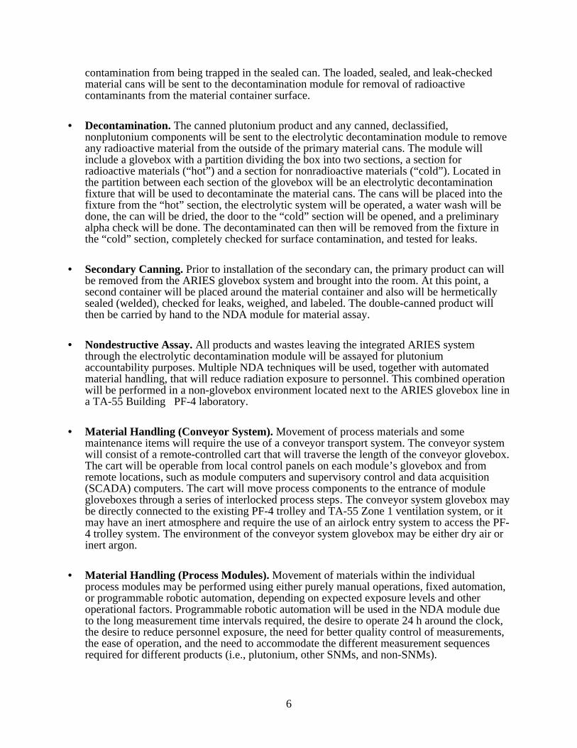
The primary function of the ARIES process will be to receive weapon pits, disassemble them,and provide a product of either a plutonium metal button or plutonium oxide powderappropriately canned to meet all requirements for long-term storage. Several integratedsubsystems (modules) will be necessary to do this, with each subsystem having a distinctfunctional requirement. A possible layout of the overall ARIES system is shown in Fig.1. Ageneral functional description of each component of the ARIES follows.
• Receiving. Selected pits will be introduced into the ARIES demonstration line through acontamination control enclosure (introduction hood) or through the existing TA-55 overheadtrolley. Once a pit is introduced into the ARIES glovebox line, the component isautomatically transferred to the various modules as required for processing, using a speciallydesigned conveyor and module access system.
• Pit Bisection and Disassembly. In this module, disassembly will consist of removal of any
appurtenances on the pit, followed by separation of the pit into two parts. This separation isdone using a bisector apparatus that works similarly to a pipe cutter. After disassembly, thevarious component materials may be separated. The plutonium-bearing materials will be sentto the next module for consolidation. Any uranium-bearing components will be packaged andprepared for transfer out of the ARIES for decontamination, and any non-special nuclearmaterial (non-SNM) components will be prepared for possible declassification operations. Adry, highly pure argon atmosphere will be required in this module to avoid any damagingsurface reactions on the hemishells.
• Plutonium Consolidation. The plutonium-bearing materials will be sent to one of two
plutonium consolidation modules. (1) The hydride/dehydride/recycle module will be used toremove the plutonium from the weapon component and consolidate it as a metal ingot. (2)The hydride-oxidation (HYDOX) module will be used to remove the plutonium from theweapon component and produce plutonium oxide. Which module is used depends on thedesired final form of the stored material. Both concepts will be used to process componentsduring the ARIES demonstration. After processing, any nonplutonium components will besent to the ARIES nondestructive assay (NDA) subsystem for assay and subsequent load-outor to a final decontamination step for residual plutonium removal followed by assay andload-out. A part- declassification module may be incorporated at this point to declassify thenonplutonium components. The plutonium products (ingot or oxide) will be sent to thecanning module for packaging. A dry, highly pure argon atmosphere will be required in thesemodules to avoid any material reactions or contamination during the handling processes.
• Primary Packaging. The consolidated plutonium metal ingot or oxide powder will be sent to
the canning module for packaging of the material in containers that are inspectable,hermetically sealed, tested for leaks, and marked primary (material). A dry, highly pureargon or helium atmosphere is essential to this module to avoid any material or gaseous
6
contamination from being trapped in the sealed can. The loaded, sealed, and leak-checkedmaterial cans will be sent to the decontamination module for removal of radioactivecontaminants from the material container surface.
• Decontamination. The canned plutonium product and any canned, declassified,
nonplutonium components will be sent to the electrolytic decontamination module to removeany radioactive material from the outside of the primary material cans. The module willinclude a glovebox with a partition dividing the box into two sections, a section forradioactive materials (“hot”) and a section for nonradioactive materials (“cold”). Located inthe partition between each section of the glovebox will be an electrolytic decontaminationfixture that will be used to decontaminate the material cans. The cans will be placed into thefixture from the “hot” section, the electrolytic system will be operated, a water wash will bedone, the can will be dried, the door to the “cold” section will be opened, and a preliminaryalpha check will be done. The decontaminated can then will be removed from the fixture inthe “cold” section, completely checked for surface contamination, and tested for leaks.
• Secondary Canning. Prior to installation of the secondary can, the primary product can will
be removed from the ARIES glovebox system and brought into the room. At this point, asecond container will be placed around the material container and also will be hermeticallysealed (welded), checked for leaks, weighed, and labeled. The double-canned product willthen be carried by hand to the NDA module for material assay.
• Nondestructive Assay. All products and wastes leaving the integrated ARIES system
through the electrolytic decontamination module will be assayed for plutoniumaccountability purposes. Multiple NDA techniques will be used, together with automatedmaterial handling, that will reduce radiation exposure to personnel. This combined operationwill be performed in a non-glovebox environment located next to the ARIES glovebox line ina TA-55 Building PF-4 laboratory.
• Material Handling (Conveyor System). Movement of process materials and some
maintenance items will require the use of a conveyor transport system. The conveyor systemwill consist of a remote-controlled cart that will traverse the length of the conveyor glovebox.The cart will be operable from local control panels on each module’s glovebox and fromremote locations, such as module computers and supervisory control and data acquisition(SCADA) computers. The cart will move process components to the entrance of modulegloveboxes through a series of interlocked process steps. The conveyor system glovebox maybe directly connected to the existing PF-4 trolley and TA-55 Zone 1 ventilation system, or itmay have an inert atmosphere and require the use of an airlock entry system to access the PF-4 trolley system. The environment of the conveyor system glovebox may be either dry air orinert argon.
• Material Handling (Process Modules). Movement of materials within the individual
process modules may be performed using either purely manual operations, fixed automation,or programmable robotic automation, depending on expected exposure levels and otheroperational factors. Programmable robotic automation will be used in the NDA module dueto the long measurement time intervals required, the desire to operate 24 h around the clock,the desire to reduce personnel exposure, the need for better quality control of measurements,the ease of operation, and the need to accommodate the different measurement sequencesrequired for different products (i.e., plutonium, other SNMs, and non-SNMs).
7
• Instrumentation and Control System. Monitoring and controlling the various processsystems within the ARIES will require an instrumentation and control system (ICS). The ICSwill be a distributed system with three levels of hierarchy. Sensors, actuators, localcontrollers, and other simple instrumentation within the module gloveboxes will make up theinstrumentation level. Programmable logic controllers (PLCs), which send and receivesignals to and from the instrumentation level and communicate among themselves over adata highway, will form the data acquisition (DAQ) system level. Module computers andSCADA computers, which connect directly to the data highway and provide the necessaryman-machine interface (MMI), will comprise the computer level. Note that, for the currentdemonstration system, the NDA is not considered part of the ICS, but rather is a separatemodule with which the ICS may communicate for NDA status messages.
ConveyorSection A
Drop Box
NDAModule
Proc
ess
Mod
ule
Proc
ess
Mod
ule
Proc
ess
Mod
ule
IntroHood
ConveyorSection B
Proc
ess
Mod
ule
Proc
ess
Mod
ule
ConveyorSection C
PassthroughAirlocks
Fig. 1. Possible Advanced Recovery and Integrated Extraction System (ARIES) GloveboxLayout.
2.2. General Configuration
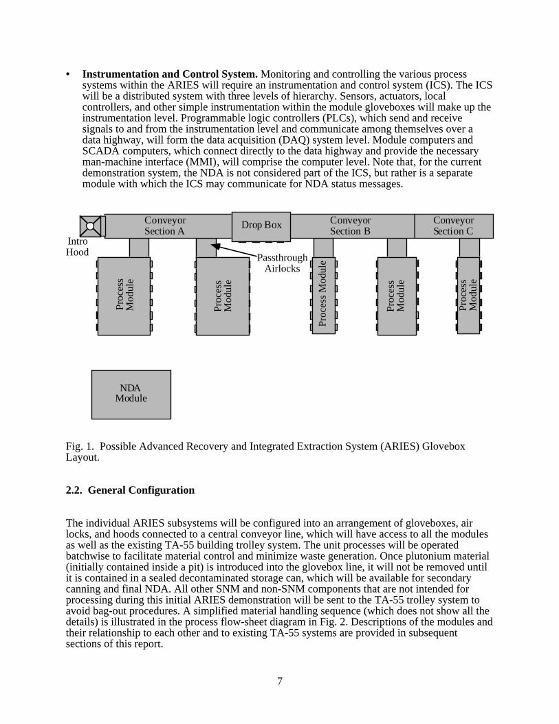
The individual ARIES subsystems will be configured into an arrangement of gloveboxes, airlocks, and hoods connected to a central conveyor line, which will have access to all the modulesas well as the existing TA-55 building trolley system. The unit processes will be operatedbatchwise to facilitate material control and minimize waste generation. Once plutonium material(initially contained inside a pit) is introduced into the glovebox line, it will not be removed untilit is contained in a sealed decontaminated storage can, which will be available for secondarycanning and final NDA. All other SNM and non-SNM components that are not intended forprocessing during this initial ARIES demonstration will be sent to the TA-55 trolley system toavoid bag-out procedures. A simplified material handling sequence (which does not show all thedetails) is illustrated in the process flow-sheet diagram in Fig. 2. Descriptions of the modules andtheir relationship to each other and to existing TA-55 systems are provided in subsequentsections of this report.
8
Dis
asse
mbl
y(B
isec
tion)
Was
te P
ack
age
and
Dec
onta
min
atio
n
Ura
nium
and
Oth
erP
arts
Dec
lass
ifica
tion
Hyd
ride-
Deh
ydrid
e(P
u m
etal
pro
duct
)
HY
DO
X(O
xide
pro
duct
)
Rec
ast
Pac
kage
Dec
onta
min
ate
Ass
ay
Ass
ay, S
ampl
ing
Inpu
t:C
lass
ified
Wea
pon
Co
mpo
nent
Pro
duct
and
Was
te:
Tra
nspa
rent
, Pac
kage
dfo
r Ind
efin
ite S
tora
ge
Fig.
2.
Sim
plif
ied
AR
IES
TA
-55
proc
ess
flow
she
et
Not
Incl
uded
inA
RIE
S P
roto
type
Dem
o
9
3. FUNCTIONAL DESIGN CRITERIA
Criteria relating to expected performance of equipment, quality considerations, safetyrequirements, and durability of materials are described in this section. General functional designcriterial (FDC) for the overall system and the common glovebox requirements are outlined inSection 3.1. In subsequent sections, FDC unique to each of the modules are presented.
3.1. Overall System and Glovebox Functional Design Criteria
• In order to reduce operator dose, the overall ARIES system must emphasize remote handlingas much as possible. Design considerations also must address industry, criticality, andradiation safety requirements for plutonium processing. The system must satisfy as-low-as-reasonably-achievable (ALARA) considerations.
• Electrical and mechanical passthroughs into the glovebox enclosure must maintain the
differential pressure between the Zone 1 and Zone 2 atmospheres in Building PF-4. • The various module gloveboxes must couple to each other by means of a conveyor glovebox
module and transport system. The overall system must also be able to interface with theexisting PF-4 overhead trolley system.
• The glovebox atmosphere in each of the modules that require an inert gas atmosphere must
be monitored for both moisture and oxygen. If a high-purity argon atmosphere is required,the glovebox must be monitored for nitrogen.
• SNM identification and control must be provided by the Material Accountability and
Safeguards System (MASS). • All gloveboxes and equipment internal to the gloveboxes must satisfy LANL seismic criteria
and must meet all TA-55 health and safety requirements for Building PF-4. • The gloveboxes should be manufactured from stainless steel and in a manner that reduces
decontamination procedures (e.g., they should have radiused corners and other appropriatefeatures). Radiation dose estimates for the components selected for processing should beconsidered in determination of shielding design. The glovebox designs must be compatiblewith the LANL procurement specifications outlined in NMT-8-PS-11610-R01 (Ref. 3).
• All gloveboxes must be made in sections short enough to enable installation into the selected
PF-4 laboratory. The gloveboxes need to be able to be transported around the v-shapedbarrier walls at the west entrance of the PF-4 facility, through the external doors of thebuilding, and through the double entrance doors of the selected laboratory.
• All gloveboxes, air locks, and passthroughs must be big enough to handle the largest of the
expected production, secondary, and waste components. Product and waste-componentstorage wells may be included in the gloveboxes to facilitate overall system operation.
• All measurement and test equipment (M&TE) must be analyzed to determine whether
periodic recalibration is required. Procedure No. QAD-301-R01, “NMT-6 CalibrationGuide” (Ref. 4) will be used as a guide in performance of the analyses.
10
3.2. Receiving Module
The ARIES receiving subsystem must conform to all TA-55 requirements for gloveboxworkstations. These requirements are outlined in a LANL Nuclear Materials TechnologyDivision (NMT) report on glovebox specifications (Ref. 3).
3.3. Disassembly Module
Mechanical disassembly operations must meet the following FDC:
• The component must be bisected to provide access to component nuclear materials that willbe amenable to the hydride/dehydride or HYDOX operations.
• The operation must limit contaminants to the fissile material that will adversely impact thechemical purity of the end product.
• The construction materials for the mechanical disassembly module must be compatible with
a dry argon environment inside the glovebox enclosure. • The bisector must be enclosed in a customized glovebox that is large enough to permit
unimpeded movement for all hands-on and remote operations, while allowing access to themachine elements required for the disassembly process.
• The disassembly module glovebox must be leak-tight and must be able to maintain an argon
atmosphere with <200 parts per million (ppm) impurities. • All electrical equipment located within the glovebox must be fully compatible with the inert
argon atmosphere. • The remote handling equipment should provide a minimum of 0.1-m separation between the
operator’s extremities and the unshielded pit.
3.4. Consolidation Modules
3.4.1. Hydride/Dehydride/Recycle Module
The following criteria must be met:
• The consolidation chamber and associated vacuum components must meet high vacuumstandards. The system must be checked for leaks and must maintain a dynamic vacuum near10-5 torr. O-ring seals must satisfy vacuum requirements at operating temperatures.
• The argon atmosphere of the glovebox must be maintained at <200 ppm impurities. • The pressure and temperature gauges must be accurate to within 0.5% of reading.
11
• The load cells that are used for reaction-rate determinations must weigh in the range of 10 kg. • The equipment items used in the consolidation process must be commercially available and
must be factory-calibrated at accuracy levels exceeding operational requirements. • Leak-checking the consolidation apparatus to meet performance standards also satisfies
safety requirements for hydrogen containment. However, routine checks for proper operationof all equipment will be necessary.
• The consolidation system must be compatible with hydrogen at the operating conditions.
Certain components must contain molten plutonium and should be nonwetting, if possible. • A reusable crucible may be used to facilitate unloading of the metal product.
3.4.2. HYDOX Module
This module must meet the following criteria:
• The HYDOX glovebox must be able to maintain a leak-tight argon atmosphere with <5 ppmimpurities. The HYDOX vacuum system must be capable of achieving vacuum in the rangeof 10-6 torr. The reactor must be leak-tight to 1x10⁻⁹ cm3/s (STP).
• The HYDOX furnace zone must be constructed from materials that are compatible with
hydrogen and oxygen at temperatures up to 950°C. • The system must use H2 and O2 totalizing flowmeters, as well as pressure controllers, to
control gas flows into the HYDOX chamber. These instruments must be accurate to within0.5% of reading. They must be compatible with hydrogen and oxygen at pressures less than1 atmosphere (atm).
• Pressure-measuring transducers must be accurate to 1% of the reading. All parts that come in
contact with hydrogen must be made of a material that does not hydrogen-embrittle and doesnot easily oxidize.
• An oxide-transferring device must be used to remove the oxide from the HYDOX crucible in
a manner that does not spill any PuO2 into the glovebox. It is desirable that this devicetransfer the oxide directly into either the primary can or an internal-material can, both ofwhich must be temporarily sealed in some manner for transport to the canning module.
• The HYDOX furnace must be required to go up to 950°C, and elements of the furnace must
be compatible with argon atmospheres. The useful operating time must exceed 1000 h.
3.5. Primary Canning Module
This module must meet the following criteria:
• The welding atmosphere in the primary canning process must be argon/helium with ≤100ppm oxygen and ≤100 ppm moisture.
• The welded containers must meet DOE standard DOE-STD-3013-94, "Criteria for the Safe
Storage of Plutonium Metals and Oxides" (Ref. 5).
12
3.6. Electrolytic Decontamination and Secondary Canning Modules
The following requirements apply to electrolytic decontamination and secondary canning:
• The decontamination module must be capable of providing the access and process totransport a primary container with a metal button or oxide from a contaminated radioactiveenvironment to an area that is free of contamination.
• The acceptable contamination levels on the primary cans, after completion of electrolytic
decontamination procedure, cannot exceed 500 disintegrations per minute (dpm)/100 cm2
direct reading (fixed) and 20 dpm/100 cm2 swipable reading. • The module must contain a system for handling the fluids used in the decontamination
process. The fluids will be recycled and purified, using ultrafiltration methods in order tominimize waste and maximize decontamination efficiency.
• The glovebox should be partitioned into separate chambers in order to provided a physical
separation of the “hot” and “cold” operations in the module. One chamber should haveaccess to an introductory hood (“cold”), and another should have access to the conveyortunnel (“hot”).
• The introduction hood is needed for removing the primary material container from the
decontamination unit and for providing a location for performing the necessary examinationprocesses on the primary.
• The welding atmosphere in the secondary canning process must be argon/helium with
< 100 ppm oxygen and < 100 ppm moisture. The welded containers are required to meet DOEStandard DOE-STD-3013-94, "Criteria for the Safe Storage of Plutonium Metal and Oxides"(Ref. 5).
• Methods for providing marking and identifying of both the primary and secondary containers
should be incorporated into the process.
3.7. Nondestructive Assay Module
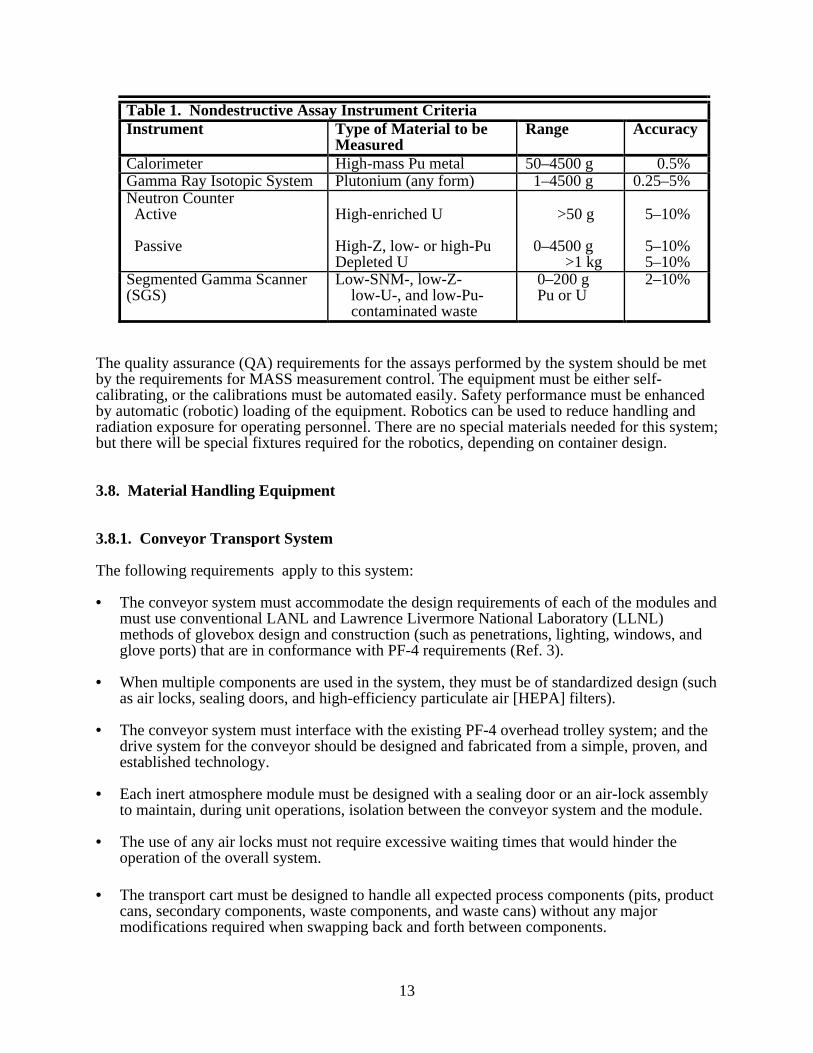
The NDA equipment chosen for use in the ARIES must be capable of providing requiredaccuracy and precision for control of SNMs during system operation. These materials may takemany forms, including low-assay wastes and deposits on nonplutonium components. Thesecriteria require NDA instruments to be of proven design and capability; although theirconfiguration in the system may be altered from traditional concepts. Table 1 lists specificoperational criteria for these instruments.
13
Table 1. Nondestructive Assay Instrument CriteriaInstrument Type of Material to be
MeasuredRange Accuracy
Calorimeter High-mass Pu metal 50–4500 g 0.5%Gamma Ray Isotopic System Plutonium (any form) 1–4500 g 0.25–5%Neutron Counter Active
Passive
High-enriched U
High-Z, low- or high-PuDepleted U
>50 g
0–4500 g >1 kg
5–10%
5–10% 5–10%
Segmented Gamma Scanner(SGS)
Low-SNM-, low-Z- low-U-, and low-Pu- contaminated waste
0–200 g Pu or U
2–10%
The quality assurance (QA) requirements for the assays performed by the system should be metby the requirements for MASS measurement control. The equipment must be either self-calibrating, or the calibrations must be automated easily. Safety performance must be enhancedby automatic (robotic) loading of the equipment. Robotics can be used to reduce handling andradiation exposure for operating personnel. There are no special materials needed for this system;but there will be special fixtures required for the robotics, depending on container design.
3.8. Material Handling Equipment
3.8.1. Conveyor Transport System
The following requirements apply to this system:
• The conveyor system must accommodate the design requirements of each of the modules andmust use conventional LANL and Lawrence Livermore National Laboratory (LLNL)methods of glovebox design and construction (such as penetrations, lighting, windows, andglove ports) that are in conformance with PF-4 requirements (Ref. 3).
• When multiple components are used in the system, they must be of standardized design (such
as air locks, sealing doors, and high-efficiency particulate air [HEPA] filters). • The conveyor system must interface with the existing PF-4 overhead trolley system; and the
drive system for the conveyor should be designed and fabricated from a simple, proven, andestablished technology.
• Each inert atmosphere module must be designed with a sealing door or an air-lock assembly
to maintain, during unit operations, isolation between the conveyor system and the module. • The use of any air locks must not require excessive waiting times that would hinder the
operation of the overall system. • The transport cart must be designed to handle all expected process components (pits, product
cans, secondary components, waste components, and waste cans) without any majormodifications required when swapping back and forth between components.
14
• The transport cart must be accessible to each module with minimal operator interface. Thecart must be capable of remote operation and, in case of equipment failure, manual operation.
• The system must be interlocked in a manner that is similar to that of an elevator, such that the
cart functions can only be activated when (1) the cart is located in front of one modulestation and (2) the door to that station has been opened.
• The system must be designed for easy maintenance in a glovebox environment and must use
readily available components.
3.8.2. Robotic Systems
The following requirements apply to this system:
• The system must provide x, y, and z Cartesian and single-axis gripper motions to pick upprocess- and waste-component containers.
• The system must provide unobstructed x-translation of the robot through the entire
(contiguous) length of the NDA framework. The system’s y-translation must permit access,as needed, to all process material locations on the NDA fixture.
• The system must provide automated material transfer for the NDA subsystem.
• The system must be designed to accommodate a maximum 10-kg load.
• The system must provide force sensors on the robot end-effector to ensure that loads arefirmly held, yet not crushed.
• The system must provide a telescoping Z arm on the robot to provide access, as needed, toprocess material.
3.9. Instrumentation and Control System
• The ICS must be able to monitor and control all conveyor glovebox ventilation and utilityservices.
• The ICS must be able to monitor and control all transport-cart and air-lock functions. • The ICS must confirm that all preconditions are met prior to initiating conveyor operations. • The ICS must provide DAQ functions as required for all modules, except NDA. • The ICS must consist of commercially available hardware and software elements with proven
performance in a similar nuclear facility. Any exceptions to these criteria shall require projectmanagement and QA review and approval on an element-by-element basis.
• The ICS must provide alarm and notification monitoring and handling for the entire ARIES. • The ICS must maintain overall system security by excluding access to uncertified personnel.
15
• The ICS must be able to monitor module process parameters for data sufficient to inform theoperator about the status and safe progress of planned events.
• The ICS must confirm that all preconditions are met before allowing operations to be
initiated. • The ICS must ensure safe shutdown of all critical control functions (such as proper
positioning of valves, maintaining position of air-lock doors, and shutting down of furnaces),in case of power failures.
17
4. EQUIPMENT DESCRIPTIONS AND MODULE OPERATION
The modules that comprise the ARIES will incorporate technologies and equipment that fulfillthe functional criteria identified previously. This section provides both a generalized descriptionof the equipment to be designed for each module and a discussion of proposed module operation.
4.1. General Glovebox and Support Functions
Each of the major modules will be housed in a commercially procured stainless steel glovebox.Requirements for additional gamma- and neutron-shielding materials on or within the gloveboxwalls will be determined for the final design. The interior walls of the glovebox will be made of304 stainless steel, and the windows will be made of safety glass. Additional external windowcoverings, for any required gamma shielding, will be made from transparent, lead-loaded glass orfrom plastic.
The support functions consist of the following components: glovebox ventilation equipment,including HEPA filter equipment and dri-trains; all utilities including electrical power, vacuumsystems, gases for pneumatic systems, and glovebox lights; process gases including hydrogen,oxygen, argon, and helium; and air-lock systems.
4.2. Conveyor Transport System
Equipment. Movement of process materials and some maintenance items within the ARIES willrequire the use of a conveyor transport system and some type of local delivery system to eachmodule. The material-handling system will consist of the following components: a conveyorglovebox that extends the length of the system, connects to all the module gloveboxes, andconnects to the Building PF-4 trolley system through an existing drop box; a conveyor transportcart that travels the length of the conveyor glovebox and delivers components to each of themodules; and a specialized platform that mounts on the conveyor transport cart andautomatically delivers/receives components to/from the entrance of each module glovebox.
Operation. The transport cart will be automatically controlled in order to transfer pits or othermaterials between the entrances of the various modules. An automatic system on the cart will beused, at the entrance of a selected module, to deliver a process component into the moduleglovebox or to retrieve a product from the module for delivery to another module. Since theexisting drop box will be used, the conveyor will also be able to deliver/retrieve componentsto/from the existing PF-4 overhead trolley system.
4.3. Receiving Module
Equipment. The receiving module will be based on standardized introduction hood designscurrently in use at TA-55. The receiving hood planned for the ARIES will accommodate one pitat a time, will be equipped with an openable front for loading, and may incorporate leaded glovesfor manual handling. The outer pit casing will provide attenuation of radiation fields andcontamination control during the load-in operation. Use of a transfer air lock between the hood
18
and the conveyor glovebox is currently being evaluated. If an air lock is used, it will also be ofstandardized design and will be sized to accommodate only one pit at a time.
Operation. The pits selected for this program may be transferred to the ARIES from the TA-55storage vault by controlled cart. Pit identification and control will be provided by the TA-55MASS. Initial NDA and any gas sampling will be performed elsewhere in TA-55 before the pitsare brought to the ARIES introduction hood. Pits may be introduced into the ARIES byremoving them from the transfer cart and placing them into the open-face hood under airatmosphere. Hood ventilation will be connected to the Zone 2 glovebox exhaust system. Theexisting standardized design at TA-55 for entry hoods will be applied to this system (Ref. 3).
After closing the receiving hood, the pits will be manually transported to the ARIES conveyorglovebox. The transfer method used depends on the type of atmosphere selected for the conveyorglovebox and whether an air lock is used.
In some cases, pits also may be introduced directly to the ARIES conveyor system through thePF-4 overhead trolley system, bypassing the receiving hood.
4.4. Disassembly Module
Equipment. The bisector will be the principal piece of equipment within this module. Thebisector machine will be similar to a commercial powered pipe cutter. It will differ, however, inthat the cutter platform will be horizontal and will remain stationary, while the pit will be rotatedby means of an electrically powered rotary table with a vacuum chuck that will securely hold thepit on the table. Several vacuum chucks will be designed to accommodate the family of pit typesanticipated for the ARIES. Use of these vacuum chucks will minimize setup time and contributeto system versatility. Incorporating a vertical axis of rotation for the bisection operation willsimplify use of any required remote handling tools and production disassembly operations. Tominimize the operator extremity radiation dose, the cutter wheel may be designed to be remotelyadvanced radially by means of a commercial stepping motor with a gear reduction drive.
Like a commercial pipe cutter, advancement of the cutter wheel will result in very large radialforces during the bisection operation. These forces will be balanced by two roller-followerwheels on the opposite side of the platform. To ensure that these large radial forces will not betransferred to the rotary table and its electric motor drive, a soft structure will be used to supportthe very rigid cutter platform. This soft support structure will also accommodate any out-of-roundness of the pit, but the structure will be sufficiently stiff to resist the reaction torque loadsproduced during the bisection process.
Additional equipment within the glovebox module will include a precision, digital mass balancefor inventory control; various gauging equipment including micrometers; remote handling toolsfor cutting, lifting, and separating subassemblies; and an overhead trolley with a minihoist forpositioning and removing the pit from the bisector machine.
A dry-pumping vacuum system will be required outside of the glovebox to provide the vacuumfor operation of all vacuum chucks.
Operation. After receipt of the pit into the pit bisector, remote handling devices may be used totransfer the pit from the conveyor delivery mechanism onto a scale. The pit will be inspected,will have any appurtenances removed, and will be weighed.
19
The pit then will be conveyed to and mounted on the bisector machine. The mounting will beaccomplished by means of custom-designed fixtures for firmly holding the pit in place. Thebisector machine incorporates many of the features of commercial powered pipe cutters. A rotarytable with a contoured vacuum chuck will hold the pit in position. The bisection cut will be madewith a chipless cutting wheel that will be radially advanced as the pit turns on the rotary table.After pit bisection, the hemishells will be transferred, one at a time, back to the scale andindividually weighed. Material accountability data will be taken and entered into the MASSsystem. The plutonium components will then be transferred out of the bisector glovebox anddelivered to one of the plutonium consolidation modules (HYDOX or hydride/dehydride). Thenonplutonium components will be transferred out of the ARIES to other TA-55 facilities throughthe PF-4 trolley system or through the introduction hood. These parts may also be sent to a futureARIES module for possible declassification procedures.
4.5. Consolidation Modules
The consolidation operation chemically separates plutonium from bonded and nested weaponsubassemblies. This operation will be carried out in one of two modules, depending on thedesired final form of the plutonium. The ARIES will be designed and built to test both types ofproduct consolidation. The hydride/dehydride/recycle module will be used to convert theplutonium in the pit hemishell directly into a metal ingot. The HYDOX module will be used toconvert the plutonium in the pit hemishell directly into an oxide. Both of these systems turn out aproduct that will be suitable for long-term storage and will be compatible with future DOEplutonium disposition options.
4.5.1. Hydride/Dehydride/Recycle Module
Equipment. A prototype hydride/dehydride/recycle system has been designed and built in PF-4;and numerous tests on a single hemishell, as well as on two stacked hemishells, have beenperformed. These tests have verified the performance of the reactor assembly in such designareas as operability, maintainability, and full-scale process viability. Preliminary studies in theprototype system have proved closed-loop recycle technology to be successful. The studies haveshown that further development of the uranium hydride beds is necessary.
The full-scale studies on the existing prototype system have provided valuable information thatwill be used in the design of a more efficient recycle vacuum system for installation in theARIES. An O-ring-sealed vacuum chamber will be designed to allow easier loading andunloading of plutonium-containing materials. The new design will make it easier to incorporatefixed automation, if required. A two-kilowatt resistive furnace, needed for the dehydridingreaction and in situ casting, will be installed around the lower vacuum chamber of the reactor.Pressure transducers, k-type thermocouples, and furnace controllers will be installed to monitorand control the recycle reaction parameters. A load cell may be used to help determine theendpoint of plutonium processing and monitor reaction rate. A new design of the fixture thatholds the plutonium component will be developed to provide easier and faster loading capability.
Studies of coating technology and of tantalum metal carburization will be used in the design ofthe reusable process crucibles. These types of coatings or treatments will be used to protectprocess crucibles from the wetting and corrosion effects of molten plutonium metal. Thesetreated reusable crucibles will be used for in situ casting within the module vacuum furnace.Calcium difluoride-coated magnesium oxide crucibles may be substituted in the event thatreusable metal crucibles do not perform as expected.
20
Operation. Operation of the hydride/dehydride module consists of placing the bondedhemishells into a vacuum system where, after processing, almost 100% of the plutonium will becollected as a metal ingot. The hydride/dehydride system will use pure hydrogen gas, generatedfrom a solid storage bed (uranium powder), to form plutonium hydride on the surface of thebonded plutonium shell. This hydride will fall from the surface into a heated receiving cruciblewhere a reverse reaction occurs, leaving behind pure plutonium metal and liberating freshhydrogen gas for further hydriding of the plutonium on the hemishell. The spallation of theplutonium hydride will be increased by a fixture that vibrates mechanically. Reuse of thehydrogen gas in this closed-loop arrangement will permit operation with a very small hydrogencharge, will greatly improve the safety margin, and will reduce the inventory of plutoniumhydride. The resulting metal ingot will be weighed, and the material accountability data will beentered on the MASS system. The product ingot will then be loaded into the primary storage canor a special internal material can and delivered to the canning module.
4.5.2. HYDOX Module
Equipment. The HYDOX reactor will consist of a stainless steel vacuum vessel with a fixture atthe top for holding the pit component, a crucible chamber for containing the product, a resistanceheating furnace, and gas feedthroughs for introducing controlled amounts of hydrogen andoxygen during processing. For ease of maintenance and operation, the internal components of thereactor will be designed to be taken out though the bottom of the vacuum vessel.
Other equipment that will be designed and built for use in the HYDOX module are thefollowing: a glovebox capable of containing the HYDOX reactor and the product powder-transfer device, a two-stage “dry-pump” vacuum system and the necessary gauging, gas handlingand metering systems for hydrogen and oxygen, thermocouples and pressure transducers formonitoring and controlling the process, remote devices for handling the components, and acomputer/process controller to monitor all variables and potentially control some of them.
In addition, a scale will be required to keep track of incoming plutonium and outgoing PuO2. Atransfer system and canning device will be designed for use in dustless transfer of the oxide tothe primary storage can. The glovebox will need sensors to measure residual hydrogen, oxygen,and water—all in the ppm range. Remote handling tools may be designed for use in mountingthe pit subassemblies into the HYDOX furnace assembly.
Operation. Remote handling devices will be used to transfer the pit hemisphere from theconveyor delivery apparatus onto a scale where the pit will be weighed. The pit will then beloaded into the HYDOX reactor, where the metal will be converted to a hydride in a similarmanner as described previously; but the hydride will be oxidized into PuO2 powder by acontrolled insertion of O2 gas into the chamber that releases the hydrogen. This process can beaccomplished in either one or two steps. The two-step process completely hydrides all theplutonium in the first step, removes all the H2 gas, and then, in a separate second step, inserts O2to oxidize the hydride to PuO2. In the one-step process, a small amount of hydrogen is used tohydride only a portion of the plutonium while, at the same time, oxygen is slowly introduced tocontinuously convert the small amount of hydride to oxide and to release the hydrogen that thenhydrides more plutonium. This process continues until all the Pu has been converted to oxide.
The two-step process is the base-line design for ARIES, but development of the one-step processwill continue to be pursued. In either case, once all the plutonium has been converted to oxide,the product will be calcined to make sure that all the hydride has been converted. A dustlesstransfer system will be used to transfer the oxide from the HYDOX reactor crucible into anappropriate material or temporary transport can. At this point, the can, lid, and oxide will all beweighed and the material accountability data entered into the MASS system. The product oxidewill be delivered to the canning module.
21
4.6. Primary Canning Module
Equipment. This module will consist of the following equipment: a glovebox to contain thecanning module equipment, a welding system to perform the welding of the lids onto theprimary-storage cans, and a leak-detection system to check for the presence of helium and toverify the integrity of the can welds. In addition, a scale will be required to maintainaccountability of the product. The glovebox will need sensors to measure residual oxygen andwater—both in the ppm range.
Operation. After consolidation, the product (metal ingot or oxide powder) will enter the canningmodule in a primary-storage can or in a special-material can compatible with the primary-storagecan. If the special-material can is used, then it will be loaded into the primary-storage can priorto performing the welding operations. The primary-storage container then will be loaded onto thelid-welding apparatus and purged with helium gas (to facilitate later leak-checking), and the lidwill be welded closed. After welding, the can will be moved to a leak-check station to determinethe integrity of the weld by detecting for helium leakage from the container. If a leak is detected,a second weld pass will be made to reseal the container. Material accountability data will beentered into the MASS system. The hermetically sealed primary-storage can then will betransferred out of the canning module and delivered to the electrolytic decontamination module.
4.7. Electrolytic Decontamination and Secondary Canning Module
Equipment. The electrolytic decontamination module will consist of the following equipment: aglovebox designed with a “hot” chamber and a “cold” chamber, a decontamination fixturemounted in the partition between the two chambers of the glovebox, an electrolyte manifold andtreatment system, a direct-current power supply to power the electrolytic decontaminationsystem, and an alpha measurement system to determine the contaminant level on the primary-storage cans immediately after they are removed from the decontamination fixture. In addition, ascale may be required to maintain accountability of the product. The glovebox will need sensorsto measure residual oxygen and water—both in the ppm range. Also, the “cold” chamber of theglovebox will contain a hood to allow removal of the canned product from the ARIES gloveboxline into the laboratory room.
A second welding system will be located outside to the glovebox in the ARIES laboratory roomto perform the welding of the lids onto the secondary cans. In addition, a system to check forhelium leaks will be used for determining the integrity of the secondary can lid welds.
Operation. After canning, the product will be transferred to the “hot” side of the electrolyticdecontamination module. The electrolytic decontamination fixture will be located in a partitionbetween the “hot” and “cold” chambers of this glovebox. The contaminated can will be placedinto the fixture from the “hot” chamber. The fixture body will be electrically connected to thenegative terminal, and the can itself will be connected to the positive terminal of a low-voltagedirect-current power supply. The electrolyte fluid will be pumped from its reservoir to the fixtureand recirculated while a low-DC voltage is applied. After the decontamination process, the canwill be rinsed with contamination-free water and then be dried. The decontaminated can will beremoved from the fixture to the “cold” chamber of the glovebox, where the can will be alphachecked to ensure that the remaining contaminant level is below specified limits. The aqueouselectrolyte used for decontamination will be recycled; and, after numerous cycles, thecontaminants will be removed from the solution as solid waste.
22
Once the primary can has been removed from the decontamination fixture on the “cold” chamberof the glovebox and it has been alpha checked to verify decontamination, the can will beremoved from the glovebox into the room. Then, it will be loaded into a secondary containermade from stainless steel and will be laser marked for identification purposes. Following aprocedure similar to that performed for the primary can, the secondary container will be loadedonto the lid-welding apparatus and purged with helium gas (to facilitate later leak-checking), andthe lid will be welded closed. After welding, the can will be moved to a leak-check station todetermine the integrity of the weld by detecting for helium leakage from the container. If a leakis detected, a second weld pass will be made to reseal the container.
Material accountability data will then be entered into the MASS system. The double-canned,sealed, laser-marked product then will be transferred out of the “cold” chamber of theelectrolytic decontamination module through an open-face hood that is under air atmosphere.The product can then will be transferred manually to the NDA module for material assay.
4.8. Nondestructive Assay Module/Robotics Support
Equipment. The NDA module will consist of the following assay instrumentation: a segmentedgamma scanner (SGS) for the assay of low-density, low-SNM material; a calorimeter/in-linegamma-ray isotopic system (GRIS) for the assay of high-plutonium-content (>50 g) items (twoinstruments); and a passive and active neutron-counting device (NCC) for the assay of high-z,low-SNM materials, both uranium and plutonium, or high-Pu (product) materials. An automatedsystem will conduct the assays by robotic manipulation of the product cans between the variousinstruments. The assay equipment will be located in an open platform (no glovebox required)with the gantry-type robot mounted overhead.
A programmable three-axis robot with specialized grippers will be used within the NDA moduleto transfer the SNM and non-SNM product cans between the various assay instruments. Therobot will be capable of moving and manipulating any anticipated ARIES load of up to 10 kg.Tooling necessary for gripping and manipulating the product and other material cans will bepurchased or fabricated.
Operation. NDA of material produced by the ARIES process will be necessary for final controland accountability of SNM. The instruments needed to analyze all of the possible materialproduced by the ARIES processes have been chosen for the NDA subsystem. The NDA systemwill be used to analyze the plutonium product (oxide or metal) within the double-cannedplutonium product containers, as well as any canned uranium or non-SNM material generated inthe ARIES process.
At the conclusion of the NDA processes, the product plutonium will meet all requirements forlong-term storage; and the cans will be sent to the TA-55 vault for interim storage. The cans willbe in an inspectable and unclassified form that is appropriate for the application of traditionalinternational safeguards. Other SNM and non-SNM items will be sent to appropriate locationswithin the TA-55 facility for further processing or storage.
23
4.9. Instrumentation and Control System
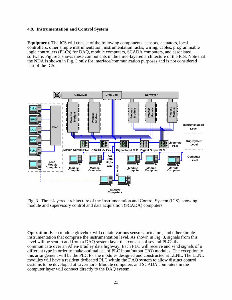
Equipment. The ICS will consist of the following components: sensors, actuators, localcontrollers, other simple instrumentation, instrumentation racks, wiring, cables, programmablelogic controllers (PLCs) for DAQ, module computers, SCADA computers, and associatedsoftware. Figure 3 shows these components in the three-layered architecture of the ICS. Note thatthe NDA is shown in Fig. 3 only for interface/communication purposes and is not consideredpart of the ICS.
ModuleComputer
ModuleComputer
SCADAComputers
ModuleComputer
ModuleComputer
ModuleComputer
Conveyor Conveyor
Motion Control PLC Analog I/O PLC Digital Input PLC Digital Output PLC
LivermorePLC
ABDataHigh-way
InstrumentationLevel
DAQ SystemLevel
ComputerLevel
NDAModule
Computers
Calor.
GRIS
SGS
NCC
Robot
NDA
Drop Box
Eth
erN
et
Pro
cess
Mo
du
le
Pro
cess
Mo
dul
e
Pro
cess
Mo
du
le
Pro
cess
Mo
dul
e
Pro
ces
sM
od
ule
Fig. 3. Three-layered architecture of the Instrumentation and Control System (ICS), showingmodule and supervisory control and data acquisition (SCADA) computers.
Operation. Each module glovebox will contain various sensors, actuators, and other simpleinstrumentation that comprise the instrumentation level. As shown in Fig. 3, signals from thislevel will be sent to and from a DAQ system layer that consists of several PLCs thatcommunicate over an Allen-Bradley data highway. Each PLC will receive and send signals of adifferent type in order to make optimal use of PLC input/output (I/O) modules. The exception tothis arrangement will be the PLC for the modules designed and constructed at LLNL. The LLNLmodules will have a resident dedicated PLC within the DAQ system to allow distinct controlsystems to be developed at Livermore. Module computers and SCADA computers in thecomputer layer will connect directly to the DAQ system.
24
A module’s control functions may reside in either a module computer or a SCADA computer.Module computers will only monitor and control their respective modules. SCADA computerswill monitor and control modules with control functions that reside in SCADA computers,monitor and control the material transport system (i.e., all shuttles, doors, air locks, and theconveyor cart), monitor the atmospheric systems (e.g., oxygen and moisture ppm), and monitormodule computers for notifications. Using a module computer will provide the benefit ofindependent system development. Using a SCADA computer will reduce the number ofcomputers in the ICS, as one SCADA computer may monitor and control several modules. Assuch, a module’s control functions may begin in a module computer during development of theARIES and be transferred to a SCADA computer during integration and operation of the ARIES.
25
5. SYSTEM LAYOUT
The ARIES process line will be installed in a selected laboratory in Building PF-4 at TA-55.Specific requirements for the location of the system within the room must be developed prior toassembly. These requirements must include the most logical layout of the process gloveboxes,utility needs, structural needs, interface needs, and needs for access to existing trolleys andservice rooms at PF-4. Many of these needs are defined in the following descriptions of layoutsand arrangements for equipment and associated gloveboxes.
5.1. Glovebox Arrangement
The ARIES includes six glovebox systems and one nonglovebox system. The conveyor gloveboxsystem will consist of two, approximately 20-ft-long, tunnel sections connected to each end of anexisting drop box in PF-4. The drop box will provide the interface connection to the current PF-4overhead trolley system. This conveyor glovebox will be located next to the back wall of thelaboratory and will have no windows or glove ports on the side next to the wall.
Attached in-line to one end of the conveyor glovebox will be the receiving hood. Attached, atvarious locations along the conveyor glovebox and mounted perpendicular to the glovebox, willbe the five major modules that make up the ARIES line (HYDOX, canning, pit bisector,hydride/dehydride, and electrolytic decontamination). All these gloveboxes will be attached tothe conveyor glovebox and will use a sealing door or a pump-down air lock to isolate the moduleatmospheres. The gloveboxes will be designed with flanged connections to facilitate gloveboxreplacements or future additions to the line. The NDA system will be located in the samelaboratory room, but it will be mounted in a nonglovebox framework that will not be connectedto the main line.
The flow of product materials in the ARIES will be from the receiving hood to the disassemblyand plutonium-processing modules, to the canning and decontamination modules, and finally,out of the glovebox line and to subsequent manual transfer to the NDA system. The materialflow-through concept for SNM accountability will require the output from one module process todirectly provide the input to the subsequent process. The final layout and process flow willaccommodate this requirement while minimizing the floor-space usage within TA-55.
5.2. Equipment Layouts
The layouts described in this section are for the ARIES modules only. Support systems, such asthe atmosphere ventilation equipment and utilities, must be arranged to optimize interaction withthe process systems and yet to minimize laboratory space needs.
The modular process equipment planned for the ARIES will be arranged in a fashion to facilitatematerial movement and to minimize radiation exposure. The layouts within each of the processmodules are described below.
• Disassembly. The pit bisector will be enclosed in an individual glovebox in a position thatwill permit unimpeded movement of all expected process components, while allowing accessto the machine elements required for the disassembly process. An overhead hoist system maybe incorporated for remote handling of the product and waste components. Vacuum
26
equipment, needed to operate the pit bisector and any other equipment, will be placed eitherunder the glovebox or as close to it as possible. External equipment will include moisture andoxygen sensors and a process power supply.
• Consolidation. Both the HYDOX and hydride/dehydride modules will be located in
individual gloveboxes. For the hydride/dehydride system, the hydrogen storage beds will belocated next to the apparatus. For the HYDOX system, the hydrogen and oxygen supplycylinders will be located outside the glovebox system with metered lines into the glovebox.In both modules, the vacuum pumping stations will be placed either under the glovebox or asclose to it as possible. Both systems will have hydrogen detectors, as well as oxygen andmoisture sensors, located in the glovebox. External equipment will include power supplies,control units for the sensors, and system process power.
• Primary Canning. The primary canning process will be located in one glovebox that
contains two workstations. The principal piece of equipment in one workstation will be thecan-welding station. The second workstation will contain the leak-checking apparatus.Adequate workspace within the box will also be an important feature. External equipmentwill include moisture and oxygen sensors and a process power supply.
• Decontamination. The decontamination glovebox will consist of a double-wide, standard-
depth glovebox that will have two isolated chambers. The "hot" chamber will be accessedfrom the conveyor glovebox through a sealing door or air lock. The "cold" chamber isaccessed through the decontamination fixture located in the wall between the two chambers.The "hot" chamber will contain the electrolytic decontamination apparatus supportingequipment. The decontamination fixture is located in the wall between the “hot” and “cold”chambers. External equipment will include moisture and oxygen sensors and a processpower supply.
• Nondestructive Assay. The layout for NDA equipment in the ARIES will use a four-well
arrangement, with each well supporting a separate instrument. The actual measurementinstruments will be located below the floor level of the open NDA support structure. Agantry-type robot will be used to automatically move the canned product or wastecomponents around the structure to the various NDA instruments.
• Instrumentation and Control System. The ICS will consist of approximately three
instrumentation racks and up to seven module and SCADA computer stations. Theinstrumentation racks will house the DAQ system of PLCs, other rack-mountedinstrumentation (such as the glovebox atmospheric monitoring systems), and associatedpower supplies. The instrumentation racks, module computers, and SCADA computers mustreside in the same room as the ARIES. The layout of the ICS will conform to standards andrecommendations contained in DOE-STD-1062-94 (Ref. 6). These requirements will ensurethat sufficient space exists around ICS equipment to allow operators and other ARIESpersonnel to perform their duties.
27
6. MATERIAL INPUTS/OUTPUTS
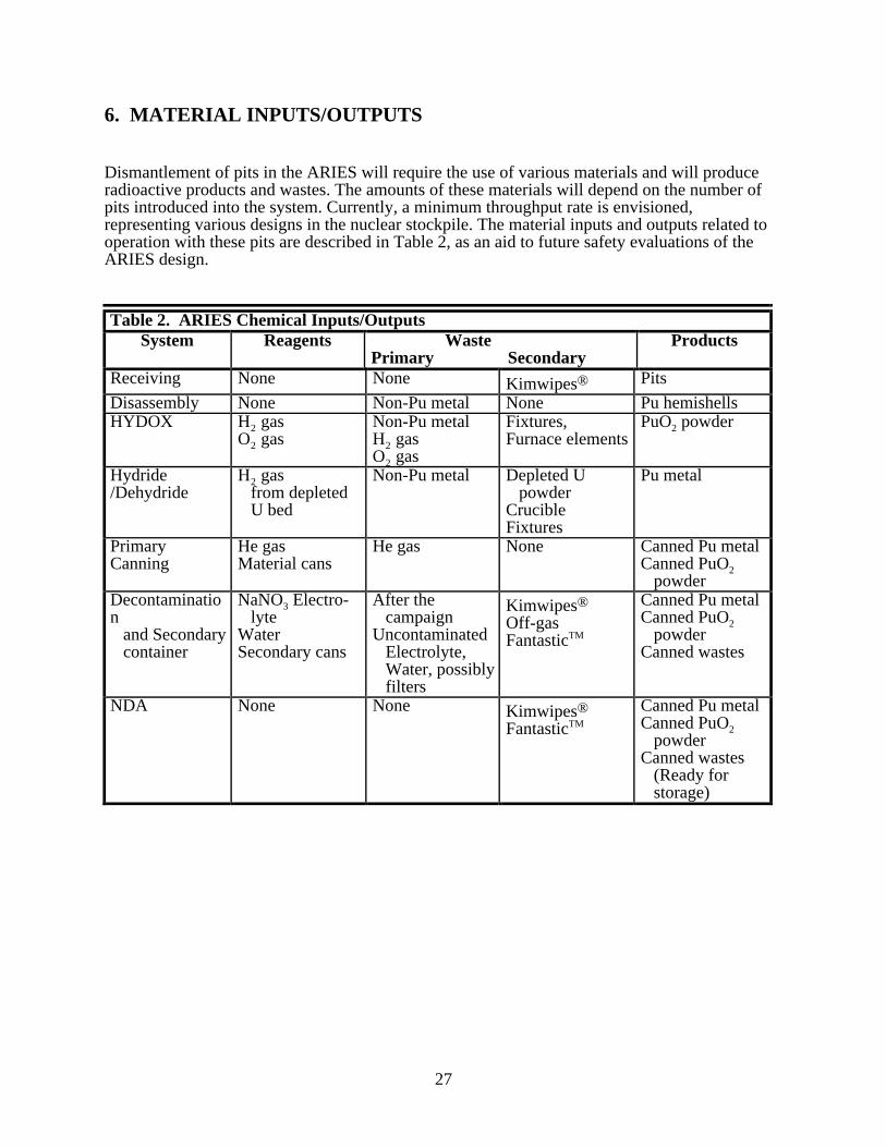
Dismantlement of pits in the ARIES will require the use of various materials and will produceradioactive products and wastes. The amounts of these materials will depend on the number ofpits introduced into the system. Currently, a minimum throughput rate is envisioned,representing various designs in the nuclear stockpile. The material inputs and outputs related tooperation with these pits are described in Table 2, as an aid to future safety evaluations of theARIES design.
Table 2. ARIES Chemical Inputs/OutputsSystem Reagents Waste
Primary SecondaryProducts
Receiving None None Kimwipes® Pits
Disassembly None Non-Pu metal None Pu hemishellsHYDOX H2 gas
O2 gasNon-Pu metalH2 gasO2 gas
Fixtures,Furnace elements
PuO2 powder
Hydride/Dehydride
H2 gas from depleted U bed
Non-Pu metal Depleted U powderCrucibleFixtures
Pu metal
PrimaryCanning
He gasMaterial cans
He gas None Canned Pu metalCanned PuO2 powder
Decontamination and Secondary container
NaNO3 Electro- lyteWaterSecondary cans
After the campaignUncontaminated Electrolyte, Water, possibly filters
Kimwipes®
Off-gasFantasticTM
Canned Pu metalCanned PuO2 powderCanned wastes
NDA None None Kimwipes®
FantasticTM
Canned Pu metalCanned PuO2 powderCanned wastes (Ready for storage)
29
7. INTERFACES
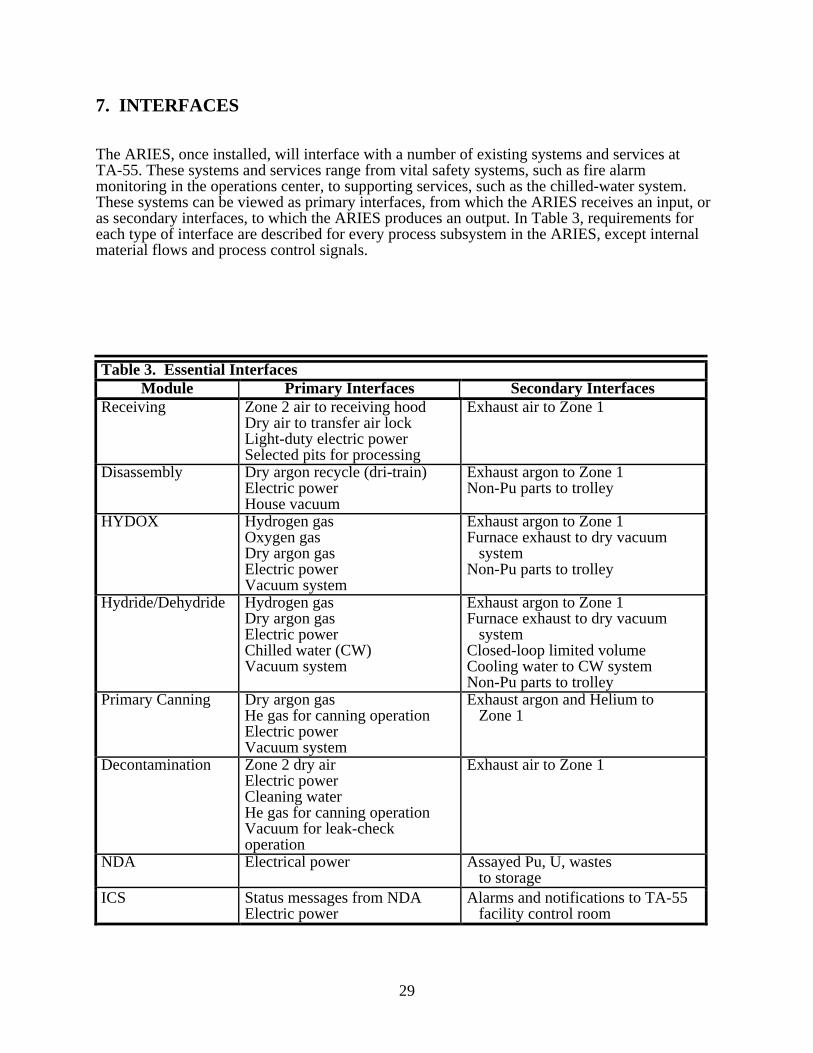
The ARIES, once installed, will interface with a number of existing systems and services atTA-55. These systems and services range from vital safety systems, such as fire alarmmonitoring in the operations center, to supporting services, such as the chilled-water system.These systems can be viewed as primary interfaces, from which the ARIES receives an input, oras secondary interfaces, to which the ARIES produces an output. In Table 3, requirements foreach type of interface are described for every process subsystem in the ARIES, except internalmaterial flows and process control signals.
Table 3. Essential InterfacesModule Primary Interfaces Secondary Interfaces
Receiving Zone 2 air to receiving hoodDry air to transfer air lockLight-duty electric powerSelected pits for processing
Exhaust air to Zone 1
Disassembly Dry argon recycle (dri-train)Electric powerHouse vacuum
Exhaust argon to Zone 1Non-Pu parts to trolley
HYDOX Hydrogen gasOxygen gasDry argon gasElectric powerVacuum system
Exhaust argon to Zone 1Furnace exhaust to dry vacuum systemNon-Pu parts to trolley
Hydride/Dehydride Hydrogen gasDry argon gasElectric powerChilled water (CW)Vacuum system
Exhaust argon to Zone 1Furnace exhaust to dry vacuum systemClosed-loop limited volumeCooling water to CW systemNon-Pu parts to trolley
Primary Canning Dry argon gasHe gas for canning operationElectric powerVacuum system
Exhaust argon and Helium to Zone 1
Decontamination Zone 2 dry airElectric powerCleaning waterHe gas for canning operationVacuum for leak-checkoperation
Exhaust air to Zone 1
NDA Electrical power Assayed Pu, U, wastes to storage
ICS Status messages from NDAElectric power
Alarms and notifications to TA-55 facility control room
30
In addition to the interfaces described in Table 3, a number of other primary and secondaryinterfaces are required to support all subsystems. These interfaces are identified as follows:
• Primary Interfaces—nonglovebox electric power, Zone 2 air supply, MASS access,telephone, and intercom access.
• Secondary Interfaces—glovebox overpressure signals to local glovebox ventilation alarms,
fire detector signals to operations center, air samples to monitors/alarms, low-level waste(LLW) handling.
Other generic support services, such as cleaning and maintenance, are not discussed due to theirvery general application to all systems in Building PF-4.
31
8. FOLLOW-ON DESIGN ACTIVITIES
In order to complete this ARIES design, many support activities leading to release of thedefinitive design packages are necessary. The key steps, after the completion of thepreconceptual design described here, are refinement of designs through the conceptual designprocess. Then the definitive designs can be completed and procurement can be started. These andother activities, including the development studies supporting the ARIES design, are described inthe ARIES Program Plan document (Ref. 1).
33
REFERENCES
1. “Advanced Recovery and Integrated Extraction System (ARIES) Program Plan,” Revision 1,Los Alamos National Laboratory document LAUR-96-866 (February 2, 1996).
2. “Advanced Recovery and Integrated Extraction System (ARIES) Technical Task
Plans/Statements of Work for FY96,” Los Alamos National Laboratory document (February1996).
3. “Procurement Specifications for Process Enclosures,” Los Alamos National Laboratory
document NMT-8-PS-11610-RO1 (December 20, 1991). 4. “NMT-6 Calibration Guide,” Los Alamos National Laboratory document QAD-301-R01;
Effective August 31, 1994; Expires August 31, 1997. 5. “Criteria for Safe Storage of Plutonium Metal and Oxides,” Department of Energy document
DOE-STD-3013-94 (1994). 6. “Human Factors Engineering Design Criteria: Volume 1, General Criteria,” Department of
Energy document DOE-STD-1062-94, (February, 1994).
APPENDIX
DOE Guidance Documentfor
ARIES Demonstration Project
Department of EnergyWashington, DC 20585
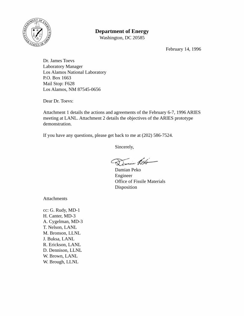
February 14, 1996
Dr. James ToevsLaboratory ManagerLos Alamos National LaboratoryP.O. Box 1663Mail Stop: F628Los Alamos, NM 87545-0656
Dear Dr. Toevs:
Attachment 1 details the actions and agreements of the February 6-7, 1996 ARIESmeeting at LANL. Attachment 2 details the objectives of the ARIES prototypedemonstration.
If you have any questions, please get back to me at (202) 586-7524.
Sincerely,
Damian PekoEngineerOffice of Fissile MaterialsDisposition
Attachments
cc: G. Rudy, MD-1H. Canter, MD-3A. Cygelman, MD-3T. Nelson, LANLM. Bronson, LLNLJ. Buksa, LANLR. Erickson, LANLD. Dennison, LLNLW. Brown, LANLW. Brough, LLNL
TNMTR
APE
D
OF ENERG
Y
ETATSDE
TIN
U
S OF AME
RIC
A
E
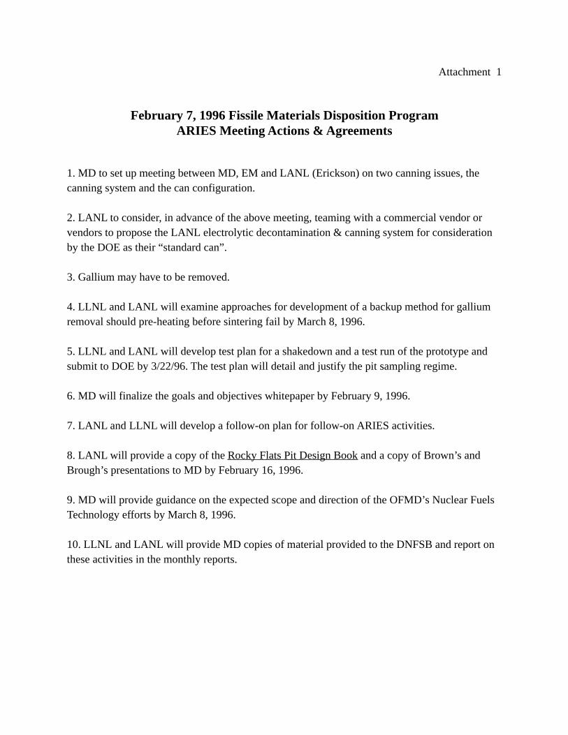
Attachment 1
February 7, 1996 Fissile Materials Disposition ProgramARIES Meeting Actions & Agreements
1. MD to set up meeting between MD, EM and LANL (Erickson) on two canning issues, thecanning system and the can configuration.
2. LANL to consider, in advance of the above meeting, teaming with a commercial vendor orvendors to propose the LANL electrolytic decontamination & canning system for considerationby the DOE as their “standard can”.
3. Gallium may have to be removed.
4. LLNL and LANL will examine approaches for development of a backup method for galliumremoval should pre-heating before sintering fail by March 8, 1996.
5. LLNL and LANL will develop test plan for a shakedown and a test run of the prototype andsubmit to DOE by 3/22/96. The test plan will detail and justify the pit sampling regime.
6. MD will finalize the goals and objectives whitepaper by February 9, 1996.
7. LANL and LLNL will develop a follow-on plan for follow-on ARIES activities.
8. LANL will provide a copy of the Rocky Flats Pit Design Book and a copy of Brown’s andBrough’s presentations to MD by February 16, 1996.
9. MD will provide guidance on the expected scope and direction of the OFMD’s Nuclear FuelsTechnology efforts by March 8, 1996.
10. LLNL and LANL will provide MD copies of material provided to the DNFSB and report onthese activities in the monthly reports.
Attachment 2
Objectives of the ARIES Prototype Demonstration
One of the stated strategies in the Office of Fissile Materials Disposition (OFMD) Strategic Planis in the context of the US plutonium stockpile, to “demonstrate the early feasibility of a processfor the disassembly, extraction and conversion of plutonium from weapons components intoforms suitable for feed for disposition and/or storage”. An additional stated strategy is to “Dem-onstrate the feasibility of a process that could be used by the US and Russia for the disassemblyand verifiable extraction and conversion of plutonium from weapons components to formssuitable for disposition.” A further stated strategy is to “Demonstrate the technologies and sys-tems that can be deployed to disposition the surplus weapons-usable plutonium so as to give theUS the basis and flexibility to initiate verifiable disposition efforts either multilaterally or bilater-ally, through negotiations”. The integrated test of ARIES is intended to support these strategies.
In keeping with the strategy of demonstration of the “early” feasibility of the process, the ARIESmust be successfully demonstrated as a production-type process by the end of FY 1997.
In keeping with the strategy of demonstration of the “feasibility of a process” applicable to theUS stockpile, the ARIES must demonstrate the functional configuration and operation of theproduction facility expected to be used for the disassembly and conversion of US weaponscomponents. The reference ARIES for the OFMD program is a prototype system installed in afacility with external support systems. As such, the ARIES must demonstrate the functionaldesign and operation of a building-based production facility. It also must be operated for suffi-cient duration to demonstrate throughput and reliability.
In keeping with the strategy of demonstrating a system that could be used by “both the US andRussia, for the verifiable extraction and conversion”, the ARIES prototype must demonstrateconversion of materials to a transparent form using processes that are acceptable to both the USand Russia. Transparency requires that the final form be able to be assayed and reveal no sensi-tive information. As such, the ARIES prototype must demonstrate packaging and assay technolo-gies acceptable to both the ISS and Russia.
In keeping with the strategy of demonstrating technology and systems to give the US the basisand “flexibility to initiate verifiable bilateral or multilateral disposition efforts”, the ARIES needsto demonstrate the flexibility to readily adapt to different constraints and incorporate differentprocesses that may be required for the disposition of foreign weapons components. As such, theARIES prototype design must emphasize simplicity and modularity. A simple, modular systemcan be more rapidly installed in a reference design facility or more readily modified to conformto different disposition needs or installation in different facilities, as might be required in supportof bilateral or multilateral disposition negotiations.

The actual demonstration equipment may have constraints imposed by the tight schedule, budgetand emplacement in TA-55. Wherever possible, functional design and operational differencesimposed by these constraints should be minimized. Where these constraints do result indifferences between the ARIES prototype and the expected production facility, these differences,their justifications and their potential impacts should be documented and this documentationincluded as a deliverable for the ARIES prototype test program.

This report has been reproduced directly from thebest available copy.
It is available to DOE and DOE contractors from theOffice of Scientific and Technical Information,P.O. Box 62,Oak Ridge, TN 37831.Prices are available from(615) 576-8401.
It is available to the public from theNational Technical Information Service,US Department of Commerce,5285 Port Royal Rd.Springfield, VA 22161.

LosN A T I O N A L L A B O R A T O R Y
AlamosLos Alamos, New Mexico 87545