Embed Size (px)
Citation preview
CAT.NO.E312154.FEB.1T(H)
Export permission by the Japanese Government may be required for exportingour products in accordance with the Foreign Exchange and Foreign Trade Law.Please contact our sales office before exporting our products. The specifications of this catalogue are subject to change without prior notice.
12-20, TOMIZAWA-CHO, NIHONBASHI, CHUO-KU, TOKYO 103-0006, JAPANPhone : 03-3808-1172Facsimile : 03-3808-1175
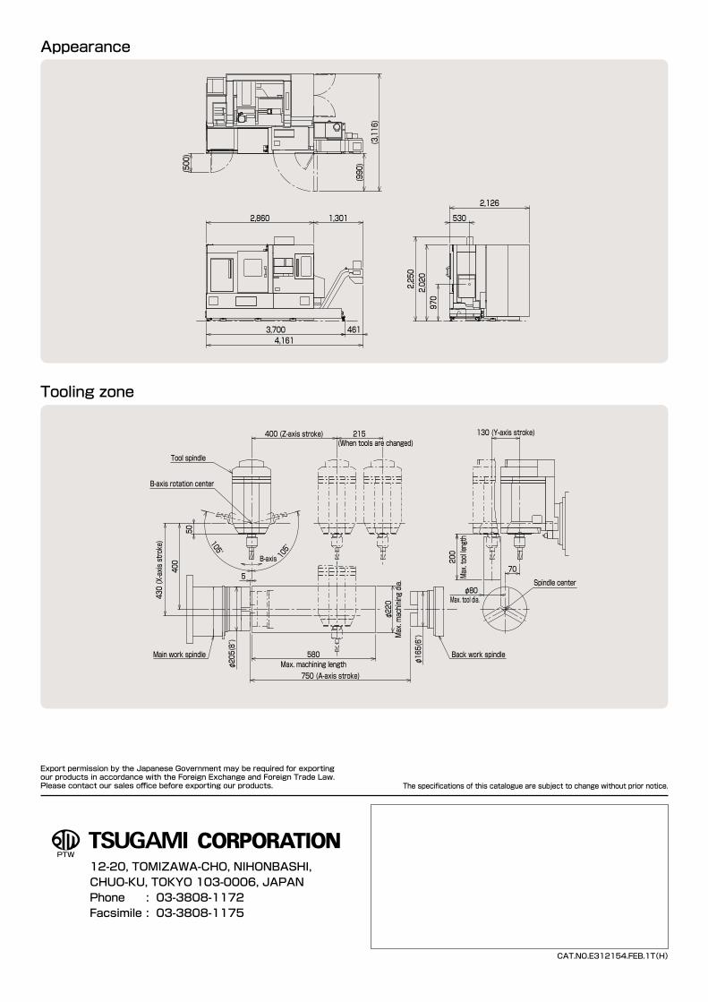
Appearance
Tooling zone
215(When tools are changed)
400 (Z-axis stroke)
105°
105°
Back work spindle
750 (A-axis stroke)
400
430 (X-axis stroke)
5Spindle center
70
130 (Y-axis stroke)
Tool spindle
B-axis rotation center
φ205(8″)
Main work spindle
φ165(6″)
200
Max. tool length
φ80Max. tool dia.
580Max. machining length
φ220
Max. machining dia.
50
B-axis
2,020
2,250
970
2,126
530
(990)
(3,116)
(500)
2,860 1,301
3,700 4614,161
Complete machining performedby the all-in-one flexible machine
Precision Turning & Machining Center
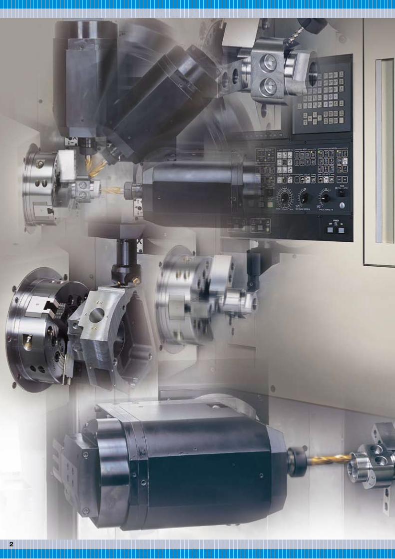
Productive complex machineby the unification of turning center functionswith machining center functions
TMA8-Ⅳ■The full-scale complex flexible productive machine with full specifications for all processes completed by the unification of turning and machining operations of this machine alone■Continuous B-axis control enables 5-axis simultaneouslycontrolled machining.
Specifications
System structure
5,000 min-1 Max.spindle speed326 Nm Max.spindle torque
X axis 30m/min, Y axis 24m/min, Z axis 40m/min Rapid traverse rate0.8sec (tool to tool) ATC
3 32
Main work spindle (8”)
Back work spindle (6”)
Main work spindle C axis(0.001°) (Cs contour control)
Back work spindle E axis(0.001°)
Back work spindle E axis(Cs contour control)
B axis (0.001°)(Driven by Direct drive motor Clamped by hydraulic at stopping)

54
Unique basic structure enables complex machining
B axis
Y axis
Workpiece
Tool spindle
◇ The B axis can index every 0.001° in ±105°capable of angular machining.
◇ Indexing of B axis is high speed and continuous motion by the direct drive motor.
◇ Control of the 130-mm stroke Y-axis enables milling at an off-center
E axis
Y axis
Z axisX axis
B axisC axis
Main workspindle
Toolspindle
Back workspindle
A axis
■Orthogonal slide structure
■Tool spindle with standard Y-axiscontrol and B-axis continuous index
■Standard high-speed ATC
■Compact structure: mechanical,electric, hydraulic and pneumaticequipment stored in the main body
■Work spindle capable of high-speedhigh-accuracy powerful cutting The spindle units control temperature by cooling oil for
prevention of heat generation from the bearings andthe built-in motors. The thermally symmetrical
structure also minimizes thermaldisplacement to ensure
long high-accuracymachining. Employmentof high-rigidity double
cylindrical roller bearings andthrust angular ball bearings in the
spindles attain powerful cutting per cutting section 2.0 mm2 with the maximum
torque 326 Nm.
One tool spindle structure that allows turning tools and milling tools
to fit in the same main spindle bore achieves powerful cutting
without any tool interference. In addition, the Y-axis control and
B-axis index that can have swivel positioning of every 0.001° in
right/left 105° performs not only horizontal front face machining but
also angular machining.
The 2-face dual contact holder held by the tool spindle bore taper
and end can perform powerful high-accuracy turning. Employment of
a 5.5-kW powerful built-in motor performs milling as powerful as a
machining center from low speed to high speed.
The cam driven ATC performs a tool-to-tool change at 0.8 sec. and a chip-to-chip change as fast as a turret-type automatic lathe by high-speed PMC, high-speed MST function, high-speed G53 function, high-speed orientation, and B-axis indexing overlap function.
■Tool magazine settable from the frontThe standard 30-tool (optional 60-tool) magazine is on the machine front so that an operator can easily change and monitor tools. It also has a mode that can manually interrupt the tool magazine without stopping automatic operation even in automatic run, which greatly improves maintainability of tools.
■Improved maintainability<IC memory card input/output function>Various data can be input/output by a memory card.<Alarm message and operator message functions>Alarm messages about the machine are indicated on the LCD.<Alarm log and operation log>Record of logs on alarms and operators facilitates a problem-cause analysis.<Overload detective function>To minimize machine damage, the load torque to the servomotor is always computed so that an abnormal value is detected to stop the machine.
■Tool spindle indexing functionThe unique 90° indexable tool spindle can reduce the number of tools and shorten the tool change time by using a multi turning holder with four turning tools that can turn back and front faces by a same tool.
Multi turning holder to index 4 positions
ATC
Tool magazine
This space saving structure improves productivity per floor area.
■5-axis simultaneously controlledspecifications is standard for NC.
The X-, Y-, and Z-axes slide orthogonally to reflect high-precision machine accuracy into machining accuracy.
The tool spindle can position at four fixed positions per 90° to ensure effective use of tools.
Back/front machining by a same turning tool
Flexible response to systematization Process integration by various operations
76
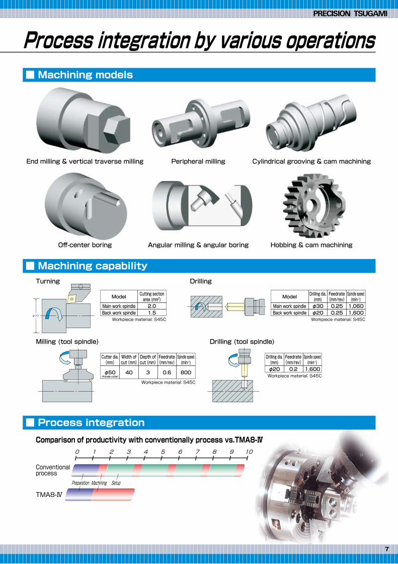
End milling & vertical traverse milling Peripheral milling Cylindrical grooving & cam machining
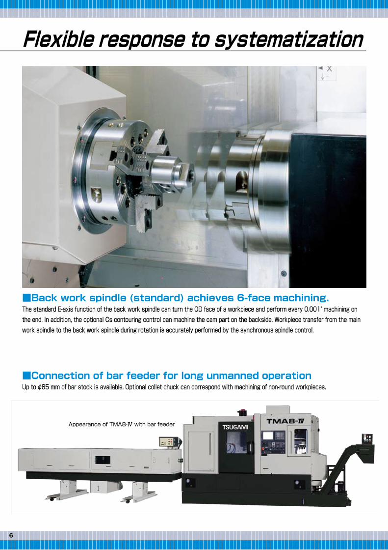
■Back work spindle (standard) achieves 6-face machining.The standard E-axis function of the back work spindle can turn the OD face of a workpiece and perform every 0.001° machining on the end. In addition, the optional Cs contouring control can machine the cam part on the backside. Workpiece transfer from the main work spindle to the back work spindle during rotation is accurately performed by the synchronous spindle control.
■Connection of bar feeder for long unmanned operationUp to φ65 mm of bar stock is available. Optional collet chuck can correspond with machining of non-round workpieces.
Off-center boring
Turning
Milling (tool spindle)
Appearance of TMA8-Ⅳ with bar feeder
Drilling
Drilling (tool spindle)
Angular milling & angular boring Hobbing & cam machining
0 1 2 3 4 5 6 7 8 9 10
Preparation Machining Setup
Conventionalprocess
TMA8-Ⅳ
Comparison of productivity with conventionally process vs.TMA8-Ⅳ
Main work spindle 2.0
Model Cutting sectionarea (mm2)
Back work spindle 1.5Workpiece material: S45C
Main work spindle φ30
Model Drilling dia.(mm)
Back work spindle φ200.25
Feedrate(mm/rev)
0.251,060
Spindle speed(min-1)
1,600Workpiece material: S45C
Workpiece material: S45Cφ50
(4-brade cutter)
Cutter dia.(mm)
40
Width ofcut (mm)
3
Depth ofcut (mm)
0.6
Feedrate(mm/rev)
800
Spindle speed(min-1)
φ20
Drilling dia.(mm)
0.2
Feedrate(mm/rev)
1,600
Spindle speed(min-1)
Workpiece material: S45C
φ70
■ Machining models
■ Machining capability
■ Process integration
Flexible response to systematization Process integration by various operations
76
End milling & vertical traverse milling Peripheral milling Cylindrical grooving & cam machining
■Back work spindle (standard) achieves 6-face machining.The standard E-axis function of the back work spindle can turn the OD face of a workpiece and perform every 0.001° machining on the end. In addition, the optional Cs contouring control can machine the cam part on the backside. Workpiece transfer from the main work spindle to the back work spindle during rotation is accurately performed by the synchronous spindle control.
■Connection of bar feeder for long unmanned operationUp to φ65 mm of bar stock is available. Optional collet chuck can correspond with machining of non-round workpieces.
Off-center boring
Turning
Milling (tool spindle)
Appearance of TMA8-Ⅳ with bar feeder
Drilling
Drilling (tool spindle)
Angular milling & angular boring Hobbing & cam machining
0 1 2 3 4 5 6 7 8 9 10
Preparation Machining Setup
Conventionalprocess
TMA8-Ⅳ
Comparison of productivity with conventionally process vs.TMA8-Ⅳ
Main work spindle 2.0
Model Cutting sectionarea (mm2)
Back work spindle 1.5Workpiece material: S45C
Main work spindle φ30
Model Drilling dia.(mm)
Back work spindle φ200.25
Feedrate(mm/rev)
0.251,060
Spindle speed(min-1)
1,600Workpiece material: S45C
Workpiece material: S45Cφ50
(4-brade cutter)
Cutter dia.(mm)
40
Width ofcut (mm)
3
Depth ofcut (mm)
0.6
Feedrate(mm/rev)
800
Spindle speed(min-1)
φ20
Drilling dia.(mm)
0.2
Feedrate(mm/rev)
1,600
Spindle speed(min-1)
Workpiece material: S45C
φ70
■ Machining models
■ Machining capability
■ Process integration

Satisfactory system built with abundant options
Mastercam 3D automatic programming
98
■Collet chuck unitsVarious collet chuck units appropriate for holding bar workpieces are prepared.
■60-tool magazineCorresponding to long unmanned operation for multi kinds of workpieces
■Workpiece catcherMachined workpieces up to φ65 mm x 250 mm x 5 kgf are discharged into a receiving box in front of the machine body.
■Oil mist collectorThe oil mist collector collects oil mist and discharges it from a mist discharge port provided on the body to prevent your factory environment from deteriorating. Central control is also possible.
■Coolant through tool spindleMaximum 7-MPa high-pressure coolant can be discharged to a tool nose from an optional high-pressure coolant system.
■Hobbing specificationsGear cutting is ensured.
■Advanced complex functions including turning/drilling/millingTurning
Holing
Milling
■Visual worry-free function on 3D displayCapable of checking the machining area and tool interference on 3D display and zooming or rotating a hidden part to check figures in details.
■Easy CAM function to create NC programs from CADHigh-operability and high-performance are assured by comprehensive PC-based CAD/CAM (design, edit, & NC programming) to create NC programs from CAD designs and product drawings.
Contouring, roughing, grooving, & boring machining paths checkable on the workpiece shape displayDrilling, tapping, reaming, boring & machining using C- and Y-axesPocketing, grooving, and 2D/3D contouring
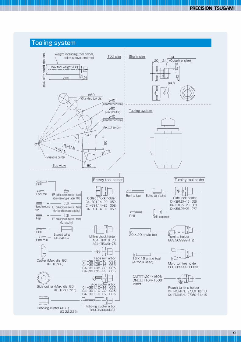
2420200
φ60 (Standard tool dia.) Weight including tool holder,
collet,sleeve, and tool
Max tool weight 4 kg
80
80
Drill
Drill
End mill Boring bar
Drill
20 × 20 angle tool
16 × 16 angle tool(4 tools used)
CN□□1204/1606DN□□1104/1506Insert
Turning holder883.369999R121
Multi turning holder880.369999R3083
Rough turning holderC4-PCLNR/L-27050-12/16C4-PDLNR/L-27050-11/15
Drill socket
Boring bar socket
End mill
Synchronoustap
Tap
ER collet (commercial item)(European-type taper 16°)
ER collet (commercial item)(for synchronous tapping)
ER collet (commercial item)(for tapping)
Straight collet (AS/ASS)
Cutter (Max. dia. 80)(ID 16/22)
Side cutter (Max. dia. 80)(ID 16/22/27)
Hobbing cutter (JIS1)(ID 22.225)
Collet chuck holderC4-391.14-20 052C4-391.14-25 052C4-391.14-32 052
12°
R175
R341.5R301.5
φ60 (Standard tool dia.) φ40
(Adjacent tool dia.)
φ40 (Adjacent tool dia.)
Max.tool section
Magazine center
φ80 (Max.tool dia.)
Top view
Tooling system
Turning tool holderRotary tool holder
Shank sizeTool size
φ40
(Coupling size)C4
24
1° 25' 56"
φ4.6
20
Milling chuck holderAC4-TRX16-70AC4-TRX20-75
Side lock holderC4-391.27-16 056C4-391.27-20 060C4-391.27-25 077
Face mill arborC4-391.05-16 032C4-391.05-16 055C4-391.05-22 025C4-391.05-22 055
Side cutter arborC4-391.10-16 025C4-391.10-22 025C4-391.10-27 025
Hobbing cutter arbor883.369999N81
Tooling system
Satisfactory system built with abundant options
Mastercam 3D automatic programming
98
■Collet chuck unitsVarious collet chuck units appropriate for holding bar workpieces are prepared.
■60-tool magazineCorresponding to long unmanned operation for multi kinds of workpieces
■Workpiece catcherMachined workpieces up to φ65 mm x 250 mm x 5 kgf are discharged into a receiving box in front of the machine body.
■Oil mist collectorThe oil mist collector collects oil mist and discharges it from a mist discharge port provided on the body to prevent your factory environment from deteriorating. Central control is also possible.
■Coolant through tool spindleMaximum 7-MPa high-pressure coolant can be discharged to a tool nose from an optional high-pressure coolant system.
■Hobbing specificationsGear cutting is ensured.
■Advanced complex functions including turning/drilling/millingTurning
Holing
Milling
■Visual worry-free function on 3D displayCapable of checking the machining area and tool interference on 3D display and zooming or rotating a hidden part to check figures in details.
■Easy CAM function to create NC programs from CADHigh-operability and high-performance are assured by comprehensive PC-based CAD/CAM (design, edit, & NC programming) to create NC programs from CAD designs and product drawings.
Contouring, roughing, grooving, & boring machining paths checkable on the workpiece shape displayDrilling, tapping, reaming, boring & machining using C- and Y-axesPocketing, grooving, and 2D/3D contouring
2420200
φ60 (Standard tool dia.) Weight including tool holder,
collet,sleeve, and tool
Max tool weight 4 kg
80
80
Drill
Drill
End mill Boring bar
Drill
20 × 20 angle tool
16 × 16 angle tool(4 tools used)
CN□□1204/1606DN□□1104/1506Insert
Turning holder883.369999R121
Multi turning holder880.369999R3083
Rough turning holderC4-PCLNR/L-27050-12/16C4-PDLNR/L-27050-11/15
Drill socket
Boring bar socket
End mill
Synchronoustap
Tap
ER collet (commercial item)(European-type taper 16°)
ER collet (commercial item)(for synchronous tapping)
ER collet (commercial item)(for tapping)
Straight collet (AS/ASS)
Cutter (Max. dia. 80)(ID 16/22)
Side cutter (Max. dia. 80)(ID 16/22/27)
Hobbing cutter (JIS1)(ID 22.225)
Collet chuck holderC4-391.14-20 052C4-391.14-25 052C4-391.14-32 052
12°
R175
R341.5R301.5
φ60 (Standard tool dia.) φ40
(Adjacent tool dia.)
φ40 (Adjacent tool dia.)
Max.tool section
Magazine center
φ80 (Max.tool dia.)
Top view
Tooling system
Turning tool holderRotary tool holder
Shank sizeTool size
φ40
(Coupling size)C4
24
1° 25' 56"
φ4.6
20
Milling chuck holderAC4-TRX16-70AC4-TRX20-75
Side lock holderC4-391.27-16 056C4-391.27-20 060C4-391.27-25 077
Face mill arborC4-391.05-16 032C4-391.05-16 055C4-391.05-22 025C4-391.05-22 055
Side cutter arborC4-391.10-16 025C4-391.10-22 025C4-391.10-27 025
Hobbing cutter arbor883.369999N81
Tooling system
1110
Available for the main and back spindles.
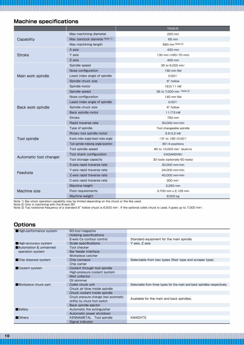
Note 1) Bar stock operation capability may be limited depending on the chuck or the like used.Note 2) Only in machining with the B-axis 90°.Note 3) Top rotational frequency of a standard 6” hollow chuck is 6,500 min-1. If the optional collet chuck is used, it goes up to 7,000 min-1.
■High-performance system
■High-accuracy system■Automation & unmanned operation system
■Chip disposal system
■Coolant system
■Workpiece chuck part
■Safety
■Others
60-tool magazineHobbing specificationsE-axis Cs contour controlScale specificationsTool checkerBar feeder interfaceWorkpiece catcherChip conveyorChip carrierCoolant through tool spindleHigh-pressure coolant systemMist collectorOil skimmerCollet chuck unitChuck air blow inside spindleChuck coolant inside spindleChuck pressure change (two automaticshifts) by chuck foot switchBack spindle ejectorAutomatic fire extinguisherAutomatic power shutdownKENNAMETAL Tool spindleSignal indicator
Standard equipment for the main spindle.Y axis, Z axis
Selectable from two types (floor type and scraper type).
Selectable from three types for the main and back spindles respectively.
KM40XTS
Max machining diameter
Max. barstock diameter Note 1)
Max machining length
X axis
Y axis
Z axis
Spindle speed
Nose configuration
Least index angle of spindle
Spindle chuck size
Spindle motor
Spindle speed
Nose configuration
Least index angle of spindle
Spindle chuck size
Back spindle motor
Stroke
Rapid traverse rate
Type of spindle
Rotary tool spindle motor
B-axis index angle/least index angle
Tool spindle indexing angle/position
Tool spindle speed
Tool shank configuration
Tool storage capacity
X-axis rapid traverse rate
Y-axis rapid traverse rate
Z-axis rapid traverse rate
C-axis rapid traverse rate
Machine height
Floor requirements
Machine weight
220 mm
65 mm
580 mm Note 2)
430 mm
130 mm (+60/-70 mm)
400 mm
35 to 5,000 min-1
190 mm flat
0.001°
8” hollow
18.5/11 kW
35 to 7,000 min-1 Note 3)
140 mm flat
0.001°
6” hollow
11/7.5 kW
750 mm
30,000 mm/min
Tool changeable spindle
5.5/2.2 kW
-15° to 195°/0.001°
90°/4 positions
80 to 10,000 min-1 (built-in)
C4(SANDVIK)
30 tools (optionally 60 tools)
30,000 mm/min
24,000 mm/min
40,000 mm/min
300 min-1
2,250 mm
3,700 mm x 2,126 mm
8,500 kg
Capability
Stroke
Main work spindle
Back work spindle
Tool spindle
Automatic tool changer
Feedrate
Machine size
TMA8-Ⅳ
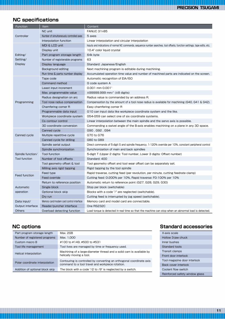
Machine specifications NC specifications
NC options Standard accessories
Options
Function
Controller
Editing/Setting/Display
Programming
Canned cycle
Spindle function/Tool function
Feed function
Automaticoperation
Data input/Output interface
Others
Item Content
Part program storage length
Number of registered programs
Custom macro B
Tool life management
Helical interpolation
Polar coordinate interpolation
Addition of optional block skip
X-axis scale
Hollow 3-jaw chuck
Inner bushes
Standard tools
Transit clamps
Front door interlock
Tool magazine door interlock
Back cover interlock
Coolant flow switch
Reinforced safety window glass
Max. 2GB
Max. 1,000
#100 to #149, #500 to #531
Tool lives are managed by time or frequency used.
The block with a code "/2 to /9" is neglected by a switch.
NC unit
Number of simultaneously controlled axes
Interpolation function
MDI & LCD unit
Display unit
Part program storage length
Number of registerable programs
Display language
Background editing
Run time & parts number display
Tape code
Command method
Least input increment
Max. programmable value
Radius designation on arc
Tool nose radius compensation
Chamfering corner R
Programmable data input
Workpiece coordinate system
Cs contour control
3D coordinate conversion
Canned cycle
Multiple repetitive cycle
Canned cycle for drilling
Spindle serial output
Spindle synchronization
Tool function
Number of tool offsets
Tool geometry offset & tool
Milling axis rigid tapping
Feed type
Feed override
Return to reference position
Single block
Optional block skip
Dry run
Memory card/modem card control interface
Reader/puncher interface
Overload detecting function
FANUC 31i-B5
5 axes
Linear interpolation and circular interpolation
Inputs and indications of normal NC commands, sequence number searches, tool offsets, function settings, tape edits, etc.
10.4" color liquid crystal
64k byte
63
Standard: Japanese/English
Next machining program is editable during machining.
Accumulated operation time value and number of machined parts are indicated on the screen.
Automatic recognition of EIA/ISO
G code system A
0.001 mm 0.001°
±99999.999 mm/° (±8 digits)
Radius value is commanded by an address R.
Compensation by the amount of a tool nose radius is available for machining (G40, G41 & G42).
Easy chamfering corner R
G10 can input data like workpiece coordinate system and the like.
G54-G59 can select one of six coordinate systems.
Linear interpolation between the main spindle and the servo axis is possible.
Commanding a swivel angle of the B-axis enables machining on a plane in any 3D space.
G90 , G92 , G94
G70 to G76
G80 to G89
Direct commands of 5-digit S and spindle frequency, 1-120% override per 10%, constant peripheral control
Synchronization of main and back spindles
5-digit T (Upper 2 digits: Tool number, Lower 3 digits: Offset number)
Standard: 400
Tool geometry offset and tool wear offset can be separately set.
Rigid tapping by the tool spindle
Rapid traverse, cutting feed (per revolution, per minute, cutting feedrate clamp)
Cutting feed: 0-200% per 10%, Rapid traverse: F0-100% per 10%
Automatic return to reference point (G27, G28, G29, G30)
Stop per block (switchable)
Blocks with a code "/" are neglected (switchable).
Cutting feed is interrupted by jog speed (switchable).
Memory card and model card are connectable.
One RS232C
Load torque is detected in real time so that the machine can stop when an abnormal load is detected.
Machining of a large-diameter thread and a solid cam is available by helically moving a tool.
Contouring is controlled by converting an orthogonal coordinate axis command to a tool travel and workpiece rotation.
1110
Available for the main and back spindles.
Note 1) Bar stock operation capability may be limited depending on the chuck or the like used.Note 2) Only in machining with the B-axis 90°.Note 3) Top rotational frequency of a standard 6” hollow chuck is 6,500 min-1. If the optional collet chuck is used, it goes up to 7,000 min-1.
■High-performance system
■High-accuracy system■Automation & unmanned operation system
■Chip disposal system
■Coolant system
■Workpiece chuck part
■Safety
■Others
60-tool magazineHobbing specificationsE-axis Cs contour controlScale specificationsTool checkerBar feeder interfaceWorkpiece catcherChip conveyorChip carrierCoolant through tool spindleHigh-pressure coolant systemMist collectorOil skimmerCollet chuck unitChuck air blow inside spindleChuck coolant inside spindleChuck pressure change (two automaticshifts) by chuck foot switchBack spindle ejectorAutomatic fire extinguisherAutomatic power shutdownKENNAMETAL Tool spindleSignal indicator
Standard equipment for the main spindle.Y axis, Z axis
Selectable from two types (floor type and scraper type).
Selectable from three types for the main and back spindles respectively.
KM40XTS
Max machining diameter
Max. barstock diameter Note 1)
Max machining length
X axis
Y axis
Z axis
Spindle speed
Nose configuration
Least index angle of spindle
Spindle chuck size
Spindle motor
Spindle speed
Nose configuration
Least index angle of spindle
Spindle chuck size
Back spindle motor
Stroke
Rapid traverse rate
Type of spindle
Rotary tool spindle motor
B-axis index angle/least index angle
Tool spindle indexing angle/position
Tool spindle speed
Tool shank configuration
Tool storage capacity
X-axis rapid traverse rate
Y-axis rapid traverse rate
Z-axis rapid traverse rate
C-axis rapid traverse rate
Machine height
Floor requirements
Machine weight
220 mm
65 mm
580 mm Note 2)
430 mm
130 mm (+60/-70 mm)
400 mm
35 to 5,000 min-1
190 mm flat
0.001°
8” hollow
18.5/11 kW
35 to 7,000 min-1 Note 3)
140 mm flat
0.001°
6” hollow
11/7.5 kW
750 mm
30,000 mm/min
Tool changeable spindle
5.5/2.2 kW
-15° to 195°/0.001°
90°/4 positions
80 to 10,000 min-1 (built-in)
C4(SANDVIK)
30 tools (optionally 60 tools)
30,000 mm/min
24,000 mm/min
40,000 mm/min
300 min-1
2,250 mm
3,700 mm x 2,126 mm
8,500 kg
Capability
Stroke
Main work spindle
Back work spindle
Tool spindle
Automatic tool changer
Feedrate
Machine size
TMA8-Ⅳ
Machine specifications NC specifications
NC options Standard accessories
Options
Function
Controller
Editing/Setting/Display
Programming
Canned cycle
Spindle function/Tool function
Feed function
Automaticoperation
Data input/Output interface
Others
Item Content
Part program storage length
Number of registered programs
Custom macro B
Tool life management
Helical interpolation
Polar coordinate interpolation
Addition of optional block skip
X-axis scale
Hollow 3-jaw chuck
Inner bushes
Standard tools
Transit clamps
Front door interlock
Tool magazine door interlock
Back cover interlock
Coolant flow switch
Reinforced safety window glass
Max. 2GB
Max. 1,000
#100 to #149, #500 to #531
Tool lives are managed by time or frequency used.
The block with a code "/2 to /9" is neglected by a switch.
NC unit
Number of simultaneously controlled axes
Interpolation function
MDI & LCD unit
Display unit
Part program storage length
Number of registerable programs
Display language
Background editing
Run time & parts number display
Tape code
Command method
Least input increment
Max. programmable value
Radius designation on arc
Tool nose radius compensation
Chamfering corner R
Programmable data input
Workpiece coordinate system
Cs contour control
3D coordinate conversion
Canned cycle
Multiple repetitive cycle
Canned cycle for drilling
Spindle serial output
Spindle synchronization
Tool function
Number of tool offsets
Tool geometry offset & tool
Milling axis rigid tapping
Feed type
Feed override
Return to reference position
Single block
Optional block skip
Dry run
Memory card/modem card control interface
Reader/puncher interface
Overload detecting function
FANUC 31i-B5
5 axes
Linear interpolation and circular interpolation
Inputs and indications of normal NC commands, sequence number searches, tool offsets, function settings, tape edits, etc.
10.4" color liquid crystal
64k byte
63
Standard: Japanese/English
Next machining program is editable during machining.
Accumulated operation time value and number of machined parts are indicated on the screen.
Automatic recognition of EIA/ISO
G code system A
0.001 mm 0.001°
±99999.999 mm/° (±8 digits)
Radius value is commanded by an address R.
Compensation by the amount of a tool nose radius is available for machining (G40, G41 & G42).
Easy chamfering corner R
G10 can input data like workpiece coordinate system and the like.
G54-G59 can select one of six coordinate systems.
Linear interpolation between the main spindle and the servo axis is possible.
Commanding a swivel angle of the B-axis enables machining on a plane in any 3D space.
G90 , G92 , G94
G70 to G76
G80 to G89
Direct commands of 5-digit S and spindle frequency, 1-120% override per 10%, constant peripheral control
Synchronization of main and back spindles
5-digit T (Upper 2 digits: Tool number, Lower 3 digits: Offset number)
Standard: 400
Tool geometry offset and tool wear offset can be separately set.
Rigid tapping by the tool spindle
Rapid traverse, cutting feed (per revolution, per minute, cutting feedrate clamp)
Cutting feed: 0-200% per 10%, Rapid traverse: F0-100% per 10%
Automatic return to reference point (G27, G28, G29, G30)
Stop per block (switchable)
Blocks with a code "/" are neglected (switchable).
Cutting feed is interrupted by jog speed (switchable).
Memory card and model card are connectable.
One RS232C
Load torque is detected in real time so that the machine can stop when an abnormal load is detected.
Machining of a large-diameter thread and a solid cam is available by helically moving a tool.
Contouring is controlled by converting an orthogonal coordinate axis command to a tool travel and workpiece rotation.
CAT.NO.E312154.FEB.1T(H)
Export permission by the Japanese Government may be required for exportingour products in accordance with the Foreign Exchange and Foreign Trade Law.Please contact our sales office before exporting our products. The specifications of this catalogue are subject to change without prior notice.
12-20, TOMIZAWA-CHO, NIHONBASHI, CHUO-KU, TOKYO 103-0006, JAPANPhone : 03-3808-1172Facsimile : 03-3808-1175
Appearance
Tooling zone
215(When tools are changed)
400 (Z-axis stroke)
105°
105°
Back work spindle
750 (A-axis stroke)
400
430 (X-axis stroke)
5Spindle center
70
130 (Y-axis stroke)
Tool spindle
B-axis rotation center
φ205(8″)
Main work spindle
φ165(6″)
200
Max. tool length
φ80Max. tool dia.
580Max. machining length
φ220
Max. machining dia.
50
B-axis
2,020
2,250
970
2,126
530
(990)
(3,116)
(500)
2,860 1,301
3,700 4614,161
Complete machining performedby the all-in-one flexible machine
Precision Turning & Machining Center


![Technical Review No.86 [New Product] Development of Sensor ... · (Left : Lathe, Right : Machining center) Main spindle of machining center Main spindle of lathe Implemented bearing](https://img.pdfslide.us/doc/110x75/5f2a1903afb0285339644a07/technical-review-no86-new-product-development-of-sensor-left-lathe-right.jpg)