Embed Size (px)
Citation preview

Precision High PerformanceMechanical Convection Incubators2050 SeriesOperating Manual and Parts List LT2071X2 Rev. 0
_________________________________________________________________________________Part of Thermo Fisher Scientific
Thermo Scientific
MANUAL NUMBER LT2071X2 (7006850)
0 -- 6/29/10 Transfer to Marietta (was LT2071X2 4/8/09) ccs
REV ECR/ECN DATE DESCRIPTION By
Preface
Precision High Performance MC Oven i
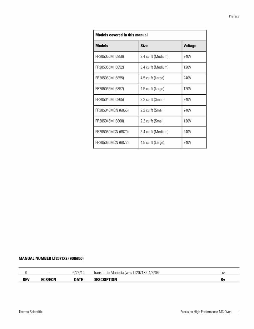
Models covered in this manual
Models Size Voltage
PR205050M (6850) 3.4 cu ft (Medium) 240V
PR205055M (6852) 3.4 cu ft (Medium) 120V
PR205060M (6855) 4.5 cu ft (Large) 240V
PR205065M (6857) 4.5 cu ft (Large) 120V
PR205040M (6865) 2.2 cu ft (Small) 240V
PR205040MCN (6866) 2.2 cu ft (Small) 240V
PR205045M (6868) 2.2 cu ft (Small) 120V
PR205050MCN (6870) 3.4 cu ft (Medium) 240V
PR205060MCN (6872) 4.5 cu ft (Large) 240V
Thermo Scientificii Precision High Performance MC Oven
Preface
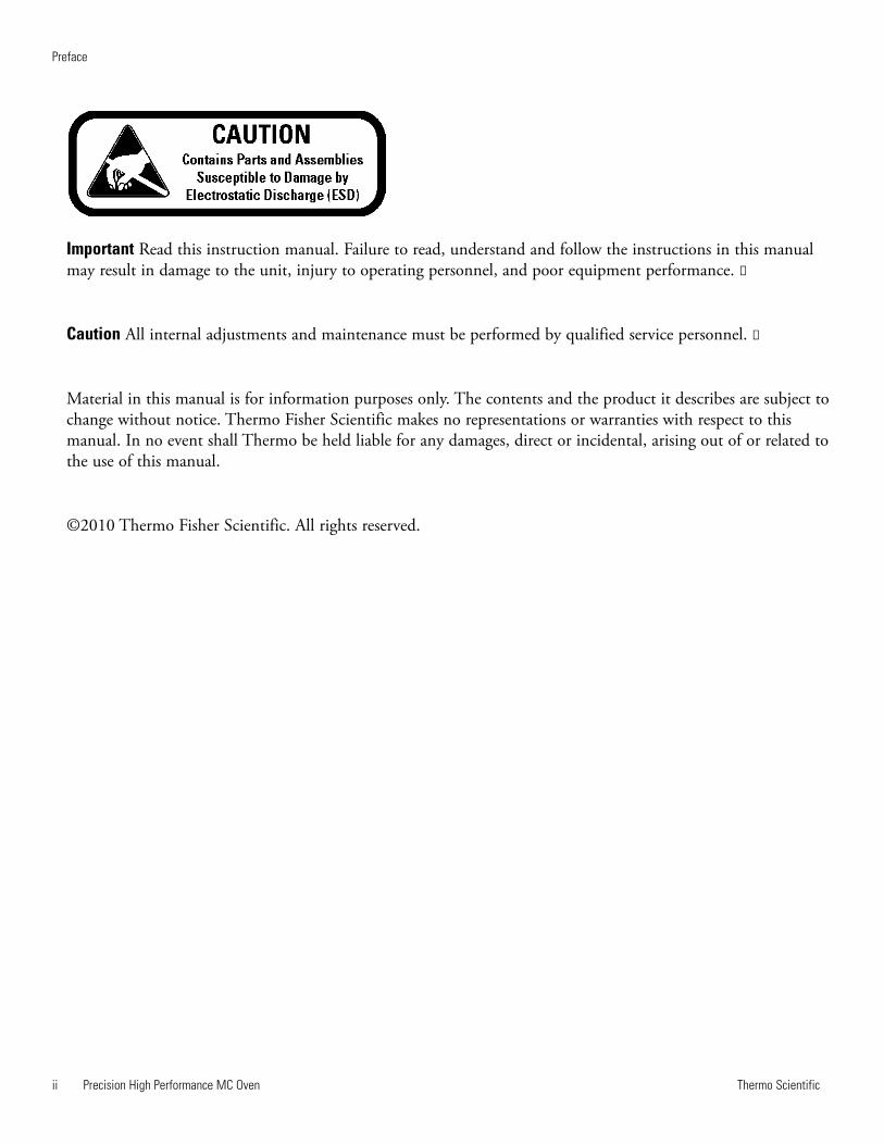
Important Read this instruction manual. Failure to read, understand and follow the instructions in this manualmay result in damage to the unit, injury to operating personnel, and poor equipment performance. s
Caution All internal adjustments and maintenance must be performed by qualified service personnel. s
Material in this manual is for information purposes only. The contents and the product it describes are subject tochange without notice. Thermo Fisher Scientific makes no representations or warranties with respect to thismanual. In no event shall Thermo be held liable for any damages, direct or incidental, arising out of or related tothe use of this manual.
©2010 Thermo Fisher Scientific. All rights reserved.
Thermo Scientific Precision High Performance MC Oven iii
Preface
Important operating and/or maintenance instructions. Read the accompanying text carefully.
Potential electrical hazards. Only qualified persons should perform procedures associated with thissymbol.
Equipment being maintained or serviced must be turned off and locked off to prevent possible injury.
Hot surface(s) present which may cause burns to unprotected skin, or to materials which may bedamaged by elevated temperatures.
Marking of electrical and electronic equipment, which applies to electrical and electronic equipmentfalling under the Directive 2002/96/EC (WEEE) and the equipment that has been put on the marketafter 13 August 2005.
This product is required to comply with the European Union’s Waste Electrical & ElectronicEquipment (WEEE) Directive 2002/96/EC. It is marked with the WEEE symbol. Thermo FisherScientific has contracted with one or more recycling/disposal companies in each EU Member StateEuropean Country, and this product should be disposed of or recycled through them. Furtherinformation on Thermo’s compliance with this directive, the recyclers in your country andinformation on Thermo products will be available at www.thermofisher.com.
4 Always use the proper protective equipment (clothing, gloves, goggles, etc.)
4 Always dissipate extreme cold or heat and wear protective clothing.
4 Always follow good hygiene practices.
4 Each individual is responsible for his or her own safety.
Thermo Scientificiv Precision High Performance MC Oven
Preface
Do You Need Information or Assistance on
Thermo Scientific Products?
If you do, please contact us 8:00 a.m. to 6:00 p.m. (Eastern Time) at:
1-740-373-4763 Direct
1-800-438-4851 Toll Free, U.S. and Canada
1-877-213-8051 FAX
http://www.thermofisher.com Internet Worldwide Web Home Page
Service E-Mail Address
Thermo Fisher Scientific
401 Millcreek Road, Box 649
Marietta, OH 45750
Our staff can provide information on pricing and give you quotations. We can
take your order and provide delivery information on major equipment items or make
arrangements to have your local sales representative contact you. Our products are listed on the
Internet and we can be contacted through our Internet home page.
Our staff can supply technical information about proper setup, operation or
troubleshooting of your equipment. We can fill your needs for spare or replacement parts or
provide you with on-site service. We can also provide you with a quotation on our Extended
Warranty for your Thermo Scientific products.
Whatever Thermo Scientific products you need or use, we will be happy to discuss your
applications. If you are experiencing technical problems, working together, we will help you
locate the problem and, chances are, correct it yourself...over the telephone without a service
call.
When more extensive service is necessary, we will assist you with direct factory trained
technicians or a qualified service organization for on-the-spot repair. If your service need is
covered by the warranty, we will arrange for the unit to be repaired at our expense and to your
satisfaction.
Regardless of your needs, our professional telephone technicians are available to assist you
Monday through Friday from 8:00 a.m. to 6:00 p.m. Eastern Time. Please contact us by
telephone or fax. If you wish to write, our mailing address is:
International customers, please contact your local Thermo Scientific distributor.
Sales Support
Service Support
Precision High Performance MC Oven vThermo Scientific
Table of Contents
Introduction . . . . . . . . . . . . . . . . . . . . . . . . . . . . . . . . . . . . . . . . . . . . . . . . .1-1
Specifications . . . . . . . . . . . . . . . . . . . . . . . . . . . . . . . . . . . . . . . . . . . . . . .2-1
Installation . . . . . . . . . . . . . . . . . . . . . . . . . . . . . . . . . . . . . . . . . . . . . . . . . .3-1Unpacking . . . . . . . . . . . . . . . . . . . . . . . . . . . . . . . . . . . . . . . . . . . . .3-1Convenience Outlet . . . . . . . . . . . . . . . . . . . . . . . . . . . . . . . . . . . . . .3-2Power Switch . . . . . . . . . . . . . . . . . . . . . . . . . . . . . . . . . . . . . . . . . . .3-2Preparing the Incubator . . . . . . . . . . . . . . . . . . . . . . . . . . . . . . . . . . .3-2
Controls . . . . . . . . . . . . . . . . . . . . . . . . . . . . . . . . . . . . . . . . . . . . . . . . . . . . .4-1Keypad . . . . . . . . . . . . . . . . . . . . . . . . . . . . . . . . . . . . . . . . . . . . . . . .4-2
Operation . . . . . . . . . . . . . . . . . . . . . . . . . . . . . . . . . . . . . . . . . . . . . . . . . . . .5-1Alarm Limits . . . . . . . . . . . . . . . . . . . . . . . . . . . . . . . . . . . . . . . . . . .5-2Safety Precautions . . . . . . . . . . . . . . . . . . . . . . . . . . . . . . . . . . . . . . .5-2Display Offsets . . . . . . . . . . . . . . . . . . . . . . . . . . . . . . . . . . . . . . . . . .5-3
Service . . . . . . . . . . . . . . . . . . . . . . . . . . . . . . . . . . . . . . . . . . . . . . . . . . . . . .6-1Cleaning . . . . . . . . . . . . . . . . . . . . . . . . . . . . . . . . . . . . . . . . . . . . . . .6-1Replacing the Door Gasket . . . . . . . . . . . . . . . . . . . . . . . . . . . . . . . .6-2Replacing the Heater . . . . . . . . . . . . . . . . . . . . . . . . . . . . . . . . . . . . .6-3Accessing the Electronics . . . . . . . . . . . . . . . . . . . . . . . . . . . . . . . . . .6-3Replacing the Circulating Fan Motor . . . . . . . . . . . . . . . . . . . . . . . . .6-4Replacing the Cooling Fan . . . . . . . . . . . . . . . . . . . . . . . . . . . . . . . . .6-4Replacing the Controller . . . . . . . . . . . . . . . . . . . . . . . . . . . . . . . . . .6-6Replacing the Solid State Relay . . . . . . . . . . . . . . . . . . . . . . . . . . . . .6-6Replacing the Safety Relay . . . . . . . . . . . . . . . . . . . . . . . . . . . . . . . . .6-7Replacing the Thermocouple . . . . . . . . . . . . . . . . . . . . . . . . . . . . . . .6-7Replacing the Glass Door . . . . . . . . . . . . . . . . . . . . . . . . . . . . . . . . . .6-8Adjusting the Door Cam . . . . . . . . . . . . . . . . . . . . . . . . . . . . . . . . . .6-9Replacing the Door Handle . . . . . . . . . . . . . . . . . . . . . . . . . . . . . . . .6-9
Troubleshooting . . . . . . . . . . . . . . . . . . . . . . . . . . . . . . . . . . . . . . . . . . . . . .7-1Replacement Parts . . . . . . . . . . . . . . . . . . . . . . . . . . . . . . . . . . . . . . . . . . .8-1Schematic . . . . . . . . . . . . . . . . . . . . . . . . . . . . . . . . . . . . . . . . . . . . . . . . . . .9-1
Section 1
Section 2
Section 3
Section 4
Section 5
Section 6
Section 8Section 7
Section 9

Precision High Performance MC Oven 1-1Thermo Scientific
Section 1 Introduction
Thermo Scientific Precision 2050 Series High Performance MechanicalConvection (MC) incubators are available in three sizes: small, mediumand large. All incubators provide PID microprocessor control at operatingtemperatures ranging from 30 (86°F) to 75°C (167°F).
Note Ambient temperature must be at least 5°C below operatingtemperatures. s
In these incubators, air is uniformly circulatedd throughout the chamberby a fan located at the bottom of the unit. An air intake located under theincubator chamber allows fresh air to enter the unit. The fresh air is heatedin a plenum, and then is circulated throughout chamber.
Temperature readouts and control parameters are shown on red LEDʼs.Three additional LEDs indicate when the heater power is being applied, anerror condition is encountered, or the temperature is being set.
The Small incubator accommodates a maximum of three shelves. TheMedium incubator holds six shelves, and the Large incubator holds 10shelves.
Precision incubators incorporate a variety of safety features. A safetybackup is built into the controller software. If the primary heater controlfails, the backup will maintain control at 3°C above the set point. Analarm LED then indicates that the backup controller is operating theincubator. A circuit breaker protects the incubator from power surges.

Precision High Performance MC Oven 2-1Thermo Scientific
Section 2 Specifications
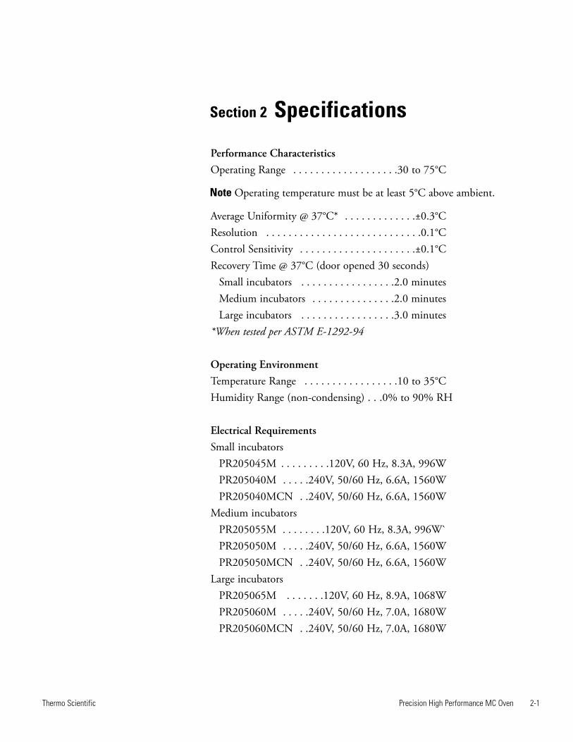
Performance CharacteristicsOperating Range . . . . . . . . . . . . . . . . . . .30 to 75°C
Note Operating temperature must be at least 5°C above ambient.
Average Uniformity @ 37°C* . . . . . . . . . . . . .±0.3°CResolution . . . . . . . . . . . . . . . . . . . . . . . . . . . .0.1°CControl Sensitivity . . . . . . . . . . . . . . . . . . . . .±0.1°CRecovery Time @ 37°C (door opened 30 seconds)
Small incubators . . . . . . . . . . . . . . . . .2.0 minutesMedium incubators . . . . . . . . . . . . . . .2.0 minutesLarge incubators . . . . . . . . . . . . . . . . .3.0 minutes
*When tested per ASTM E-1292-94
Operating EnvironmentTemperature Range . . . . . . . . . . . . . . . . .10 to 35°CHumidity Range (non-condensing) . . .0% to 90% RH
Electrical RequirementsSmall incubators
PR205045M . . . . . . . . .120V, 60 Hz, 8.3A, 996WPR205040M . . . . .240V, 50/60 Hz, 6.6A, 1560WPR205040MCN . .240V, 50/60 Hz, 6.6A, 1560W
Medium incubatorsPR205055M . . . . . . . .120V, 60 Hz, 8.3A, 996W`PR205050M . . . . .240V, 50/60 Hz, 6.6A, 1560WPR205050MCN . .240V, 50/60 Hz, 6.6A, 1560W
Large incubatorsPR205065M . . . . . . .120V, 60 Hz, 8.9A, 1068WPR205060M . . . . .240V, 50/60 Hz, 7.0A, 1680WPR205060MCN . .240V, 50/60 Hz, 7.0A, 1680W
2-2 Precision High Performance MC Oven Thermo Scientific
Section 2Specifications
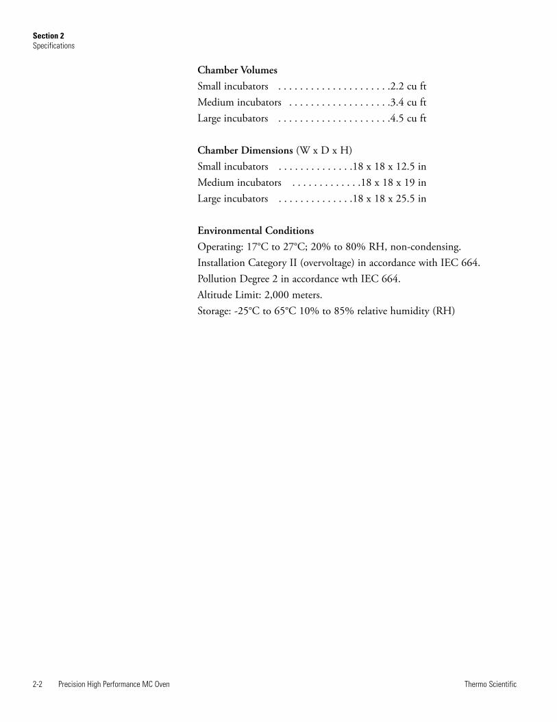
Chamber VolumesSmall incubators . . . . . . . . . . . . . . . . . . . . .2.2 cu ftMedium incubators . . . . . . . . . . . . . . . . . . .3.4 cu ftLarge incubators . . . . . . . . . . . . . . . . . . . . .4.5 cu ft
Chamber Dimensions (W x D x H)Small incubators . . . . . . . . . . . . . .18 x 18 x 12.5 inMedium incubators . . . . . . . . . . . . .18 x 18 x 19 inLarge incubators . . . . . . . . . . . . . .18 x 18 x 25.5 in
Environmental ConditionsOperating: 17°C to 27°C; 20% to 80% RH, non-condensing.Installation Category II (overvoltage) in accordance with IEC 664.Pollution Degree 2 in accordance wth IEC 664.Altitude Limit: 2,000 meters.Storage: -25°C to 65°C 10% to 85% relative humidity (RH)
Precision High Performance MC Oven 3-1Thermo Scientific
Section 3 Installation
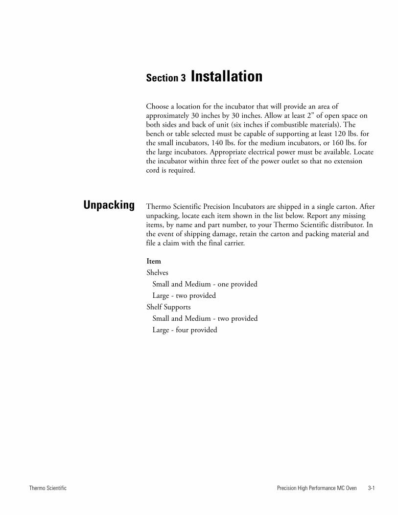
Choose a location for the incubator that will provide an area ofapproximately 30 inches by 30 inches. Allow at least 2” of open space onboth sides and back of unit (six inches if combustible materials). Thebench or table selected must be capable of supporting at least 120 lbs. forthe small incubators, 140 lbs. for the medium incubators, or 160 lbs. forthe large incubators. Appropriate electrical power must be available. Locatethe incubator within three feet of the power outlet so that no extensioncord is required.
Thermo Scientific Precision Incubators are shipped in a single carton. Afterunpacking, locate each item shown in the list below. Report any missingitems, by name and part number, to your Thermo Scientific distributor. Inthe event of shipping damage, retain the carton and packing material andfile a claim with the final carrier.
ItemShelves
Small and Medium - one providedLarge - two provided
Shelf SupportsSmall and Medium - two providedLarge - four provided
Unpacking
3-2 Precision High Performance MC Oven Thermo Scientific
Section 3Installation
Preparing theIncubator
To prepare the incubator for operation, perform the following procedures:
1. Install the shelf(s).
2. Make certain all packing material has been removed from incubatorchamber.
3. Connect the line cord to an appropriate electrical outlet.
4. The incubator is now ready for operation. No preliminary adjustmentsare required. Depending on the customer application and customerlaboratory procedures, an initial calibration may be done at this point.
Caution See data plate on incubator for voltage, current and line frequencyspecifications. Check that the power requirements of the incubator will notoverload the circuit. s
Note The incubator received a single point calibration at 120°C, ±2°C atthe factory. If greater accuracy is required, the user may require a standardlaboratory calibration (see Calibration section). s
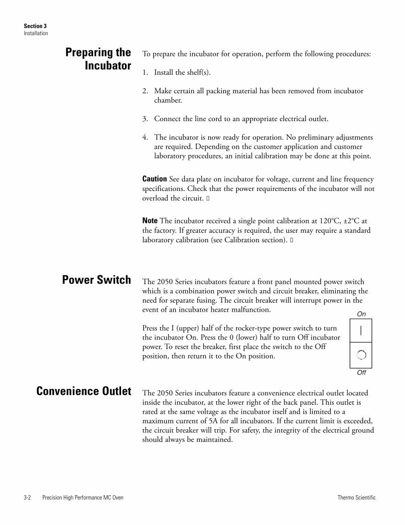
The 2050 Series incubators feature a front panel mounted power switchwhich is a combination power switch and circuit breaker, eliminating theneed for separate fusing. The circuit breaker will interrupt power in theevent of an incubator heater malfunction.
Press the I (upper) half of the rocker-type power switch to turnthe incubator On. Press the 0 (lower) half to turn Off incubatorpower. To reset the breaker, first place the switch to the Offposition, then return it to the On position.
The 2050 Series incubators feature a convenience electrical outlet locatedinside the incubator, at the lower right of the back panel. This outlet israted at the same voltage as the incubator itself and is limited to amaximum current of 5A for all incubators. If the current limit is exceeded,the circuit breaker will trip. For safety, the integrity of the electrical groundshould always be maintained.
Power Switch
On
Off
Convenience Outlet
Precision High Performance MC Oven 4-1Thermo Scientific
Section 4 Controls
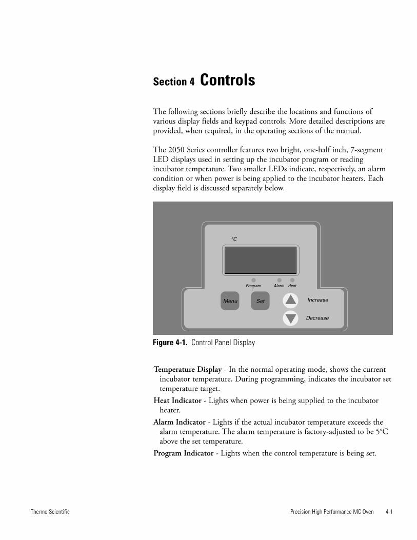
The following sections briefly describe the locations and functions ofvarious display fields and keypad controls. More detailed descriptions areprovided, when required, in the operating sections of the manual.
The 2050 Series controller features two bright, one-half inch, 7-segmentLED displays used in setting up the incubator program or readingincubator temperature. Two smaller LEDs indicate, respectively, an alarmcondition or when power is being applied to the incubator heaters. Eachdisplay field is discussed separately below.
Temperature Display - In the normal operating mode, shows the currentincubator temperature. During programming, indicates the incubator settemperature target.
Heat Indicator - Lights when power is being supplied to the incubatorheater.
Alarm Indicator - Lights if the actual incubator temperature exceeds thealarm temperature. The alarm temperature is factory-adjusted to be 5°Cabove the set temperature.
Program Indicator - Lights when the control temperature is being set.
Figure 4-1. Control Panel Display
4-2 Precision High Performance MC Oven Thermo Scientific
Section 4Controls
Keypad The 2050 Series incorporates a four-key, tactile keypad. The function ofeach key is discussed individually below. Refer to Figure 4-1.
Pressing the MENU Key will cause display to show CAL. Then pressingSET Key will display calibration.
Pressing INCREASE Arrow Key while holding down the SET Keyincreases the incubator set temperature, as indicated on the temperaturedisplay.
Pressing the DECREASE Arrow Key while holding down the SET Keydecreases the incubator set temperature, as indicated on the temperaturedisplay.
Pressing the SET Key causes the display to show the set temperature. Usedwith INCREASE Arrow Key and DECREASE Arrow Key to change theset temperature. With MENU Key to access entry of a temperature displayoffset (calibration feature).
Precision High Performance MC Oven 5-1Thermo Scientific
Section 5 Operation
In Control mode operation, the incubator maintains a set temperatureuntil that set temperature is changed. The Actual and Set Displays willindicate current chamber temperature and the temperature set point,respectively. To set a temperature and initiate Control mode operation,perform the following.
1. Place the power switch in the ON position. All 8s will flash as a test ofthe display.
2. Press and hold the SET Key.
3. Observe the set temperature in the Set Display window.
4. To decrease the set temperature, press the DECREASE Key whileholding the SET Key.
5. To increase the set temperature, press the INCREASE Key whileholding the SET Key.
6. When the desired set temperature is shown, release the INCREASEOR DECREASE Key. Finally, release the SET Key. The incubatorautomatically begins to control at the set temperature.
Note To rapidly increase or decrease the set temperature, press and holdthe appropriate key. To slowly increment or decrement the set temperature1° at a time, press and immediately release the key. s
Note Upon initial heat up to temperature, the over range alarm indicatorlight may illuminate briefly (several minutes) until the temperaturestabilizes at the set point. The incubator temperature should be allowed tostabilize prior to loading samples. s
5-2 Precision High Performance MC Oven Thermo Scientific
Section 5Operation
Before operating the incubator, always observe the following SafetyPrecautions:
This unit is not explosion proof, do not use in the presence of flammableor combustible materials; fire or explosion may result. Unit containscomponents, which may ignite such materials.
Fumes and spillage from acidic solutions cause corrosion of the stainlesssteel chamber and other components. Care should be taken to maintain aneutral pH at all times.
The heater is in the bottom of the unit. Surface temperatures at thebottom cover may be higher than set point temperature.
For Example: A plastic container setting on the heater cover may becomehot enough to melt/burn the container at settings below the melting pointof plastic. Do not place items on the heater cover.
• Wear insulated gloves
• Use tongs
• Never stand in front of an open incubator
• Use safety goggles
The 2050 Series controllers feature a deviation alarm which alerts theoperator and interrupts heater power whenever the actual incubatortemperature differs from the set temperature by more than 3°C. This setlimit cannot be adjusted by the operator.
If the actual temperature exceeds the alarm limit, the alarm indicator LEDwill light and the Display will flash “EEE.”
The reference point for the alarm is the set temperature. Any change in theset temperature will cause a corresponding shift in the alarm temperature.
Example:
If the set temperature is 40°C, the alarm will trip at 43°C. If the settemperature is changed to 50°C, the alarm will follow the set temperatureand trip at 53°C.
Changing the set temperature to a value more than 3°C below the presentincubator temperature will trip the alarm. Power is removed from theheater when an alarm condition occurs.
Safety Precautions
Alarm Limits
As an example:
An experiment was being run at 50°C. The experiment finished andanother researcher needed to run an experiment at 40°C. The researcherreset the setpoint to 40 and the unit went into alarm. The researcher,knowing this was a normal operation, allowed the unit to cool and stabilizeat 40°C. Just below 43 degrees, the unit alarm LED went off and thedisplay resumed normal operation.
The 2050 Series controllers permit the operator to select a display offsettemperature. With a display offset entered, the temperature displayed willbe the actual incubator temperature (measured at the controlthermocouple) plus or minus the display offset selected. Functionally, theoffset feature permits the operator to measure and calibrate such that thedisplay will indicate the temperature at a specific point or zone within theincubator.
To enter a display offset, perform the following steps:
1. Press the MENU Key, the display will indicate –
2. To view the present offset value, press and hold the SET Key.
3. To change the display offset, press and hold the SET Key. Press theINCREASE Key or DECREASE Key until the display indicates thedesired offset.
4. Release the SET Key.
5. Press MENU Key Once to return to normal temperature control.
Example:
The displayed temperature is the result of algebraically adding the actualtemperature to the offset value. Thus, if an offset value of -3° is being used,a measured temperature of 50° will be displayed as 47°.
Precision High Performance MC Oven 5-3Thermo Scientific
Section 5Operation
Display Offsets
Alarm Limits(continued)

Section 6 Service
The following sections describe procedures for servicing the 2050 Seriesincubators. The procedures, Replacing the Door Gasket, Replacing thedoor handle, and adjusting the door handle may be performed by mostusers. However, all other service procedures involve possible exposure toline voltage. Only qualified service personnel should undertake theseprocedures. The second section, Accessing the Electronics Compartment,describes procedures required for subsequent service sections and isreferenced by these later sections when required.
If needed, call Technical Services for assistance.
Caution Service procedures involve exposure to line voltage and should beperformed only by qualified service personnel. Disconnect incubator frompower source before attempting repairs. s
Caution Allow incubator to cool to ambient temperature before attemptingrepair. s
Caution Only factory authorized components should be used for allrepairs. Failure to use factory authorized replacement components will voidwarranty and could result in unit malfunction and or hazardous operatingconditions. s
1. Always unplug unit prior to cleaning.
2. During cleaning, take precautions to prevent cleaning agents fromcontacting electrical components.
3. Use a mild, non-abrasive cleaner (i.e. damp cloth and mild soap) toclean all normally accessible surfaces.
4. Make sure unit is dry before re-connecting to power source.
Precision High Performance MC Oven 6-1Thermo Scientific
Cleaning
Precision 2050 Series incubators incorporate a durable, silicone door gasketto minimize heat loss. Should the gasket become defective or be damaged,it may be replaced by following the procedure below.
Note Study the method of door gasket attachment before startingdisassembly. Understanding will avoid confusion later in this process. s
1. Set the power switch to off position and open chamber door.
2. Carefully remove and retain hardware from door hinges (case side). Laydoor on a flat surface with the handle over the edge.
3. Note the joint position of the old gasket. This is where the new gasketinstallation will start.
4. Bend back the old door gasket and remove the Phillips head screwsattaching the gasket.
5. Remove the old door gasket.
6. Loosely install two screws through the stainless steel liner and into thedoor wrap to align these pieces during the installation of the newgasket. Once one side of the new gasket is installed, these screws willneed to be removed to install the new gasket.
7. Begin installing the replacement gasket at the joint position of the oldgasket. Stretch the replacement gasket around the corners of the linerto avoid bunching up of the gasket material.
8. Install a Phillips head screw as the gasket rounds each corner to keepthe gasket properly stretched (the screw goes through the liner, piercesthe gasket and threads into the door wrap).
9. After all four corners are secured, install the remainder of the Phillipshead screws. Make sure there is no gap at the gasket joint; stretch thegasket slightly, if necessary.
10. Reinstall the door onto the case with hinges.
6-2 Precision High Performance MC Oven Thermo Scientific
Section 6Service
Replacing the DoorGasket
Precision High Performance MC Oven 6-3Thermo Scientific
Section 6Service
To access the electronics compartment, proceed as follows:
1. Disconnect power cord from the electrical outlet. carefullyremove andretain hardware from door hinges (case side). Set door aside.
2. Slide unit back until the front of the bezel (control panel) is at least 3inches from edge of bench top.
3. Prop up the front of the incubator by placing a shim under each frontfoot. Use shims between 1½ and 2 inches in thickness.
4. Remove the screws securing bezel from top of the incubator.
5. Grasp bezel and pull top outward. Bezel will disengage from fascia. Laybezel on top of the unit.
To replace a defective heater, proceed as follows:
1. Disconnect power cord from the electrical outlet.
2. Remove the outer chamber door and glass door.
3. Remove the two screws securing the plenum in place, then removeplenum.
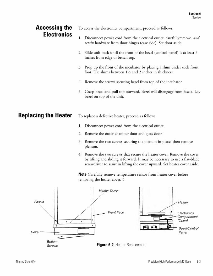
4. Remove the two screws that secure the heater cover. Remove the coverby lifting and sliding it forward. It may be necessary to use a flat-bladescrewdriver to assist in lifting the cover upward. Set heater cover aside.
Note Carefully remove temperature sensor from heater cover beforeremoving the heater cover. s
Accessing theElectronics
Replacing the Heater
Heater Cover
Front Face
BottomScrews
Fascia
Bezel
Heater
ElectronicsCompartment(Open)
Bezel/ControlPanel
Figure 6-2. Heater Replacement
4. Remove the two nuts and shake-proof washers securing the heaterleads, then pull the lead terminals off the heater studs.
6. Remove the two screws securing heater to cabinet. Slide heater forwardto disengage back heater clips, lift back of heater up, then slide heaterback and lift out.
7. Install replacement heater and reassemble unit by generally reversingthe steps above.
To replace a defective cooling fan, proceed as follows:
1. Disconnect power cord from the electrical outlet. Carefully remove andretain hardware from door hinges (case side). Set door aside.
2. Slide the unit back until the front of the bezel (control panel) is at least3 inches from edge of bench top.
3. Prop up the front of the incubator by placing a shim under each frontfoot. Use shims between 1½ and 2 inches in thickness.
4. Remove the screws securing bezel from bottom of the incubator.
5. Grasp bezel and pull top outward. Bezel will disengage from fascia. Laybezel aside on bench top.
6. Remove the two mounting screws holding the fan in place.
7. Remove the two fan power wires from push-on terminals located onfan housing.
8. Install replacement fan and reassemble oven by generally reversing thesteps above.
Note When installing the replacement fan, make certain air flow arrowmolded into fan housing points out of the incubator chassis. s
Caution Sheet metal in this area is sharp. Work carefully. s
To replace a defective circulating fan motor, proceed as follows:
1. Disconnect power cord from the electrical outlet. Carefully remove andretain hardware from door hinges (case side). Set door aside.
6-4 Precision High Performance MC Oven Thermo Scientific
Section 6Service
Replacing the CoolingFan
Replacing theCirculating Fan Motor
Replacing the Heater(continued)

2. Slide the unit back until the front of the bezel (control panel) is at least3 inches from edge of bench top.
3. Prop up the front of the incubator by placing a shim under each frontfoot. Use shims between 1½ and 2 inches in thickness.
4. Remove the screws securing bezel from bottom of the incubator.
5. Grasp bezel and pull top outward. Bezel will disengage from fascia. Laybezel aside on bench top.
6. Remove the outer chamber door and glass door.
7. Remove the two screws that secure the plenum in place, then removethe plenum.
8. Remove the six screws that secure the heater cover. Remove the coverby lifting and sliding it forward. It may be necessary to use a flat-bladescrewdriver to assist in lifting the cover upward. Set heater cover aside.
Note Carefully remove the temperature sensor from heater cover beforeremoving the cover. s
9. Using an Allen wrench, loosen set-screw holding the fan wheel ontothe motor shaft. Observe the shaft has a flat side to prevent the set-screw from turning on the shaft. Remove the gasket cover and gasketthrough which the motor shaft protrudes.
10. Locate the two electrical leads from the fan motor. Remove the leadsfrom the push-on terminal strip located in the front of the oven bezel.
11. Lay the incubator on its back with the bottom facing forward.
12. Detach the controller housing (incubator bottom) by removing theeight screws which fasten it to the cabinet. Two screws are located oneach side of the incubator and four on the bottom.
13. Locate the two access holes for the motor mounting nuts located in thefloor, in front of and in back of the motor shaft.
14. Push an 11/32-in nut driver through the front access hole, gentlypushing aside the insulation until the nut driver reaches the frontmotor mounting nut.
15. Remove front nut and washer, then repeat process using back accesshole to remove back motor mounting nut and washer.
16. Remove the fan motor by sliding it out.
17. Install replacement fan motor by generally reversing the steps above.
Precision High Performance MC Oven 6-5Thermo Scientific
Section 6Service
Replacing CirculatingFan Motor (cont.)
To replace a defective controller, proceed as follows:
1. Disconnect power cord from the electrical outlet.
2. Open the chamber door. Carefully remove and retain hardware fromdoor hinges (case side). Set door aside.
3. Remove the screws securing bezel from top of the incubator.
4. Grasp bezel and pull top outward. Bezel will disengage from fascia. Laybezel on top of the unit.
5. Locate terminal blocks on controller, remove all wires connected tocontroller. Note color and location of wires.
6. Remove four screws that hold controller to bezel, then remove oldcontroller.
7. Install new replacement controller and reattach wires previouslyremoved.
8. Check wiring connections against schematic, making sure that the linepower wiring is attached to the proper terminal, i.e. 120V or 230V.
9. Check switch DS 1 setting: Switches A and B should be OFF.
To replace a defective solid state relay, proceed as follows:
1. Disconnect power cord from the electrical outlet.
2. Open the chamber door. Carefully remove and retain hardware fromdoor hinges (case side). Set door aside.
3. Remove the screws securing bezel from top of the incubator.
4. Grasp bezel and pull top outward. Bezel will disengage from fascia. Laybezel on top of the unit.
5. Consult the schematic and locate the solid state relay (mounted onbezel).
6. Remove four lead wires from their screw-down terminals.
7. Remove two Phillips screws which mount the solid state relay to thebezel.
8. Lift out the solid state relay. Put new solid state relay in place, makingcertain that the thin, conductive pad remains between the solid staterelay and the bezel.
9. Generally reverse the steps above to reassemble incubator.
6-6 Precision High Performance MC Oven Thermo Scientific
Section 6Service
Replacing the SolidState Relay
Replacing theController

To replace a defective safety relay, proceed as follows:
1. Disconnect power cord from the electrical outlet.
2. Open the chamber door. Carefully remove and retain hardware fromdoor hinges (case side). Set door aside.
3. Remove the screws securing bezel from top of the incubator.
4. Grasp bezel and pull top outward. Bezel will disengage from fascia. Laybezel on top of the unit.
5. Consult the schematic and locate the safety relay (mounted on bezel).
6. Remove four lead wires from their push-on terminals.
7. Remove two Phillips screws which mount the safety relay to the bezel.
8. Lift out the safety relay.
9. Generally reverse the steps above to install the replacement safety relayand reassemble incubator.
To replace a defective control thermocouple, proceed as follows:
To replace a defective control thermocouple, proceed as follows:
1. Disconnect power cord from the electrical outlet. Carefully remove andretain hardware from door hinges (case side). Set door aside.
2. Slide the unit back until the front of the bezel (control panel) is at least3 inches from edge of bench top.
3. Prop up the front of the incubator by placing a shim under each frontfoot. Use shims between 1½ and 2 inches in thickness.
4. Remove the screws securing bezel from bottom of the incubator.
5. Grasp bezel and pull top outward. Bezel will disengage from fascia. Laybezel aside on bench top.
6. Locate the thermocouple connections on the controller.
7. Remove the thermocouple wires by loosening two securing screws.
Precision High Performance MC Oven 6-7Thermo Scientific
Section 6Service
Replacing theThermocouple
Replacing the SafetyRelay
(continued)
8. The Small units have the thermocouple located on the roof of thechamber, locate clip which holds thermocouple in place. Removethermocouple from clip.
OR
On Medium and Large incubators, the control thermocouple is locatedunder the bottom plenum. Remove the glass door and bottom plenumto access the thermocouple.
9. Pull thermocouple forward into chamber, exposing roughly a 6 inchsection of the thermocouple wire.
10. Cut the thermocouple wire to remove the thermocouple sheath.
11. Securely loop together the cut end of the defective thermocouple withthe two leads of the replacement thermocouple. Wrap masking tapeover the length of the loops to secure them.
12. Gently pull the defective thermocouple out through the electronicscompartment while guiding ("fishing") the replacement thermocoupleinto place.
13. Generally reverse Steps 1 through 7 to complete installation of newthermocouple and reassemble incubator.
Note Observe position in terminal for each lead. When re-connecting, becertain to observe polarity. Compare with polarity indication on controllerhousing. For thermocouples, the red wire is negative and yellow positive. s
The Precision 2050 Series incubators feature a glass inner door to allow thechamber to be viewed with minimal heat loss. Should the glass doorbecome damaged, it may be replaced by following the procedures below.
1. While holding the glass door, loosen the set screws on insides of upperand lower hinges of glass door.
2. Remove old glass door and set aside.
3. Generally reverse steps above to install replacement glass door. Adjusthinge position until gap between door and frame is roughly equal onall sides.
Caution While loosening hinge set screws, continue to grasp the glass door.When the set screws are loosened, the door is freed and will fall out if notheld. s
6-8 Precision High Performance MC Oven Thermo Scientific
Section 6Service
Replacing the GlassDoor
Replacing theThermocouple (cont.)
To replace a defective door handle, perform the steps below:
1. Remove the two mounting screws holding latch cover in place.
2. Remove the two mounting screws holding defective handle in place.
3. Mount the replacement handle using two screws.
4. Adjust bottom nut (13/16) from end of shaft.
5. Secure latch cover in place with two screws.
Due to handling in shipment or to heat distortion with use, the door cammay require adjustment. To adjust the door cam, perform the following:
Caution Allow door to cool! s
1. Open door and remove screws holding latch cover in place.
2. Locate nuts securing tongue on cam shaft.
3. Loosen but do not remove outside nut.
4. Adjust inside nut, one full turn clockwise draws door 1/16” closer tocabinet when door is closed.
5. Secure cam tongue in place by tightening outside nut.
6. Repeat 1 thru 5 as necessary to get desired door seal.
7. Secure latch cover in place with two screws.
Precision High Performance MC Oven 6-9Thermo Scientific
Section 6Service
Replacing the DoorHandle
Adjusting the DoorCam

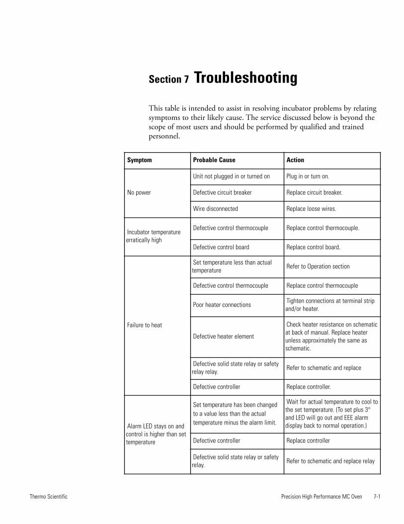
Section 7 Troubleshooting
This table is intended to assist in resolving incubator problems by relatingsymptoms to their likely cause. The service discussed below is beyond thescope of most users and should be performed by qualified and trainedpersonnel.
Precision High Performance MC Oven 7-1Thermo Scientific
Symptom Probable Cause Action
No power
Unit not plugged in or turned on Plug in or turn on.
Defective circuit breaker Replace circuit breaker.
Wire disconnected Replace loose wires.
Incubator temperatureerratically high
Defective control thermocouple Replace control thermocouple.
Defective control board Replace control board.
Failure to heat
Set temperature less than actualtemperature Refer to Operation section
Defective control thermocouple Replace control thermocouple
Poor heater connections Tighten connections at terminal stripand/or heater.
Defective heater element
Check heater resistance on schematicat back of manual. Replace heaterunless approximately the same asschematic.
Defective solid state relay or safetyrelay relay. Refer to schematic and replace
Defective controller Replace controller.
Alarm LED stays on andcontrol is higher than settemperature
Set temperature has been changed to a value less than the actual temperature minus the alarm limit.
Wait for actual temperature to cool tothe set temperature. (To set plus 3°and LED will go out and EEE alarmdisplay back to normal operation.)
Defective controller Replace controller
Defective solid state relay or safetyrelay. Refer to schematic and replace relay
7-2 Precision High Performance MC Oven Thermo Scientific
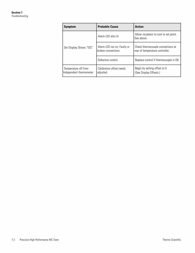
Section 7Troubleshooting
Symptom Probable Cause Action
Set Display Shows “EEE”
Alarm LED also lit Allow incubator to cool to set point.See above.
Alarm LED not on; Faulty orbroken connections
Check thermocouple connections atrear of temperature controller.
Defective control Replace control if thermocouple is OK.
Temperature off fromIndependent thermometer
Calibration offset needsadjusted.
Begin by setting offset to 0. (See Display Offsets.)
Section 8 Replacement Parts
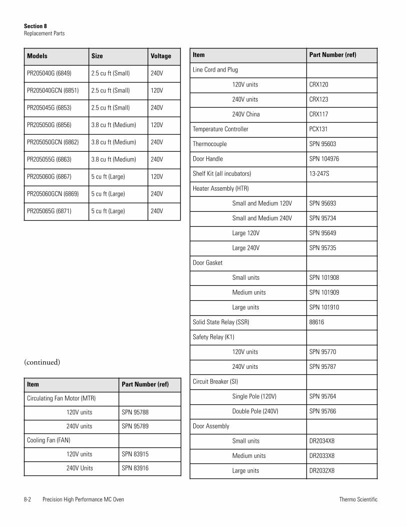
Note Only factory authorized components should be used for repair. s
Replacements for incubator parts may be ordered, by part number, fromcustomer service.
Precision High Performance MC Oven 8-1Thermo Scientific
8-2 Precision High Performance MC Oven Thermo Scientific
Section 8Replacement Parts
Item Part Number (ref)
Line Cord and Plug
120V units CRX120
240V units CRX123
240V China CRX117
Temperature Controller PCX131
Thermocouple SPN 95603
Door Handle SPN 104976
Shelf Kit (all incubators) 13-247S
Heater Assembly (HTR)
Small and Medium 120V SPN 95693
Small and Medium 240V SPN 95734
Large 120V SPN 95649
Large 240V SPN 95735
Door Gasket
Small units SPN 101908
Medium units SPN 101909
Large units SPN 101910
Solid State Relay (SSR) 88616
Safety Relay (K1)
120V units SPN 95770
240V units SPN 95787
Circuit Breaker (SI)
Single Pole (120V) SPN 95764
Double Pole (240V) SPN 95766
Door Assembly
Small units DR2034X8
Medium units DR2033X8
Large units DR2032X8
Models Size Voltage
PR205040G (6849) 2.5 cu ft (Small) 240V
PR205040GCN (6851) 2.5 cu ft (Small) 120V
PR205045G (6853) 2.5 cu ft (Small) 240V
PR205050G (6856) 3.8 cu ft (Medium) 120V
PR205050GCN (6862) 3.8 cu ft (Medium) 240V
PR205055G (6863) 3.8 cu ft (Medium) 240V
PR205060G (6867) 5 cu ft (Large) 120V
PR205060GCN (6869) 5 cu ft (Large) 240V
PR205065G (6871) 5 cu ft (Large) 240V
Item Part Number (ref)
Circulating Fan Motor (MTR)
120V units SPN 95788
240V units SPN 95789
Cooling Fan (FAN)
120V units SPN 83915
240V Units SPN 83916
(continued)
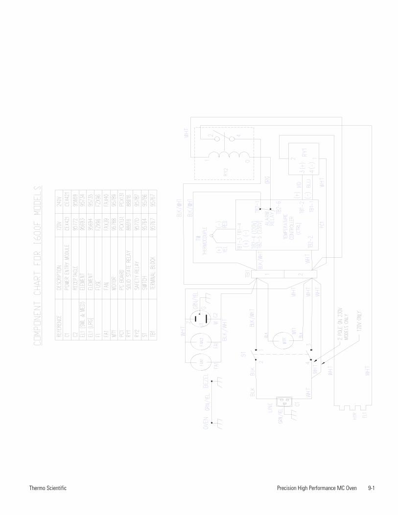
Precision High Performance MC Oven 9-1Thermo Scientific


Thermo Scientific401 Millcreek RoadMarietta, Ohio 45750United States
www.thermofisher.com