Embed Size (px)
Citation preview
Tool clamping systems
Precision Collet Chucks CENTRO|PTapping Chucks SYNCHRO|T
G ER GOZ
G B
Taper Shanks JIS B 6339 with Face Contact MAS/BTP30 (AD) 51 MAS/BTP40 (AD) 53
2 FAHRION || Tool clamping systems
Hollow Tapers DIN 69893 / ISO 12164 HSK-A32 21 HSK-A40 22 HSK-A50 25 HSK-A63 28 HSK-A80 32 HSK-A100 33
Hollow Tapers DIN 69893 HSK-E25 34 HSK-E32 35 HSK-E40 36 HSK-E50 37 HSK-E63 38 HSK-F50 38 HSK-F63 39
Polygonal Shanks ISO 26623-1 C3 40 C4 41 C5 42 C6 43 C8 44
Taper Shanks JIS B 6339 MAS/BT30 (AD) 45 MAS/BT40 (AD•AD/B) 47 MAS/BT50 (AD•AD/B) 50
Taper Shanks ANSI B.50 CAT40 (AD/B) 55 CAT50 (AD/B) 57
Cylindrical Shanks Z (AD) 58
Taper Shanks similar to DIN 69871 (Wood working) A30 (AD) 59
Taper Shanks DIN 69871 AD30 16 AD40-AD/B40 17 AD50-AD/B50 20
Page
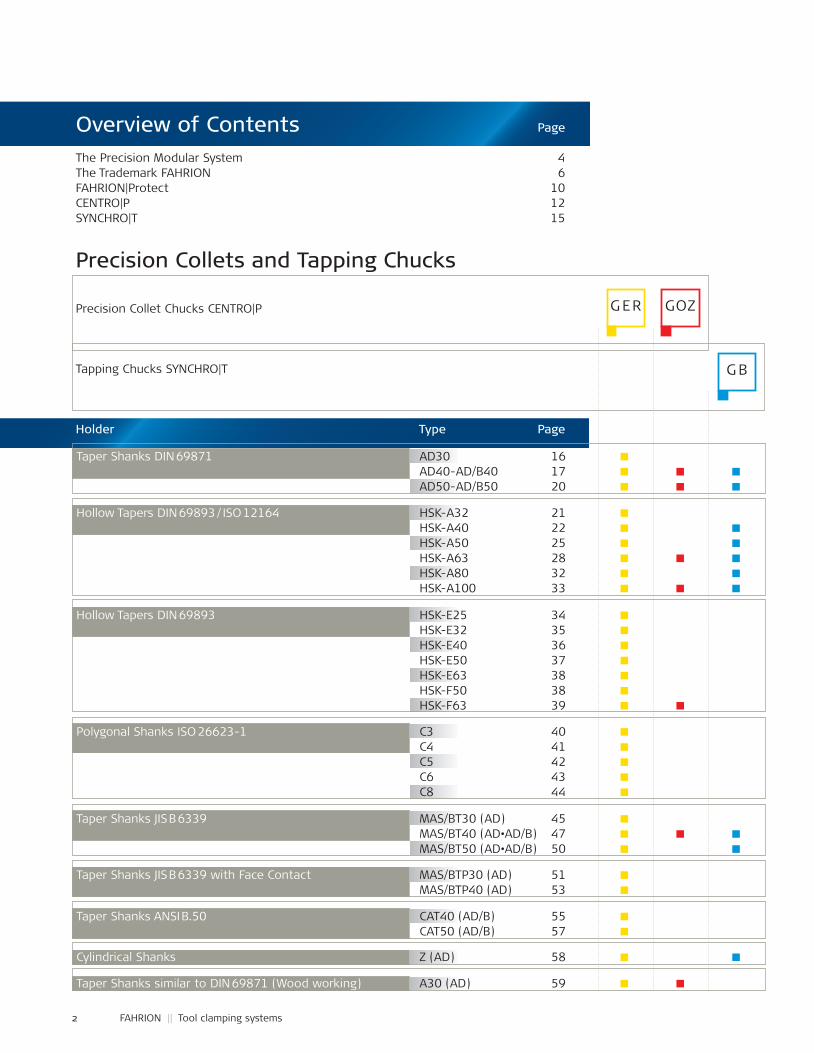
The Precision Modular System 4The Trademark FAHRION 6FAHRION|Protect 10CENTRO|P 12SYNCHRO|T 15
Precision Collets and Tapping Chucks
Precision Collet Chucks CENTRO|P
Tapping Chucks SYNCHRO|T
Holder Type Page
Overview of Contents
3
G ER GOZ
G B
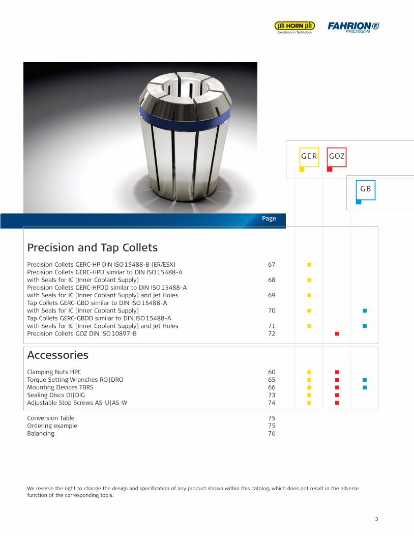
Precision and Tap ColletsPrecision Collets GERC-HP DIN ISO 15488-B (ER/ESX) 67 Precision Collets GERC-HPD similar to DIN ISO 15488-A with Seals for IC (Inner Coolant Supply) 68 Precision Collets GERC-HPDD similar to DIN ISO 15488-A with Seals for IC (Inner Coolant Supply) and Jet Holes 69 Tap Collets GERC-GBD similar to DIN ISO 15488-A with Seals for IC (Inner Coolant Supply) 70 Tap Collets GERC-GBDD similar to DIN ISO 15488-A with Seals for IC (Inner Coolant Supply) and Jet Holes 71 Precision Collets GOZ DIN ISO 10897-B 72
AccessoriesClamping Nuts HPC 60 Torque Setting Wrenches RO | DRO 65 Mounting Devices TBRS 66 Sealing Discs DI | DIG 73 Adjustable Stop Screws AS-U | AS-W 74
Conversion Table 75Ordering example 75Balancing 76
We reserve the right to change the design and speci£cation of any product shown within this catalog, which does not result in the adverse function of the corresponding tools.
Page
4 FAHRION || Tool clamping systems
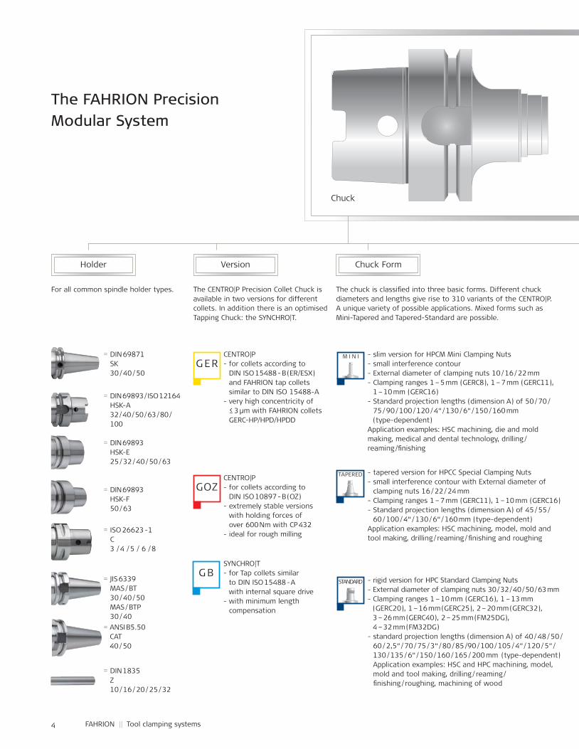
The FAHRION Precision Modular System
Chuck
Holder Chuck FormVersion
The CENTRO|P Precision Collet Chuck is available in two versions for different collets. In addition there is an optimised Tapping Chuck: the SYNCHRO|T.
The chuck is classi£ ed into three basic forms. Different chuck diameters and lengths give rise to 310 variants of the CENTRO|P. A unique variety of possible applications. Mixed forms such as Mini-Tapered and Tapered-Standard are possible.
For all common spindle holder types.
CENTRO|P- for collets according to
DIN ISO 15488 - B (ER/ESX) and FAHRION tap collets similar to DIN ISO 15488-A
- very high concentricity of≤ 3 µm with FAHRION collets GERC-HP/HPD/HPDD
CENTRO|P- for collets according to
DIN ISO 10897 - B (OZ)- extremely stable versions
with holding forces of over 600 Nm with CP 432
- ideal for rough milling
SYNCHRO|T- for Tap collets similar
to DIN ISO 15488 - A with internal square drive
- with minimum lengthcompensation
- slim version for HPCM Mini Clamping Nuts- small interference contour- External diameter of clamping nuts 10 / 16 / 22 mm- Clamping ranges 1 – 5 mm (GERC8), 1 – 7 mm (GERC11),
1 – 10 mm (GERC16)- Standard projection lengths (dimension A) of 50 / 70 /
75 / 90 / 100 / 120 / 4“ / 130 / 6“ / 150 / 160 mm (type-dependent)
Application examples: HSC machining, die and mold making, medical and dental technology, drilling / reaming /£ nishing
- tapered version for HPCC Special Clamping Nuts- small interference contour with External diameter of
clamping nuts 16 / 22 / 24 mm- Clamping ranges 1 – 7 mm (GERC11), 1 – 10 mm (GERC16)- Standard projection lengths (dimension A) of 45 / 55 /
60 / 100 / 4“ / 130 / 6“ / 160 mm (type-dependent)Application examples: HSC machining, model, mold and tool making, drilling / reaming / £ nishing and roughing
- rigid version for HPC Standard Clamping Nuts- External diameter of clamping nuts 30 / 32 / 40 / 50 / 63 mm- Clamping ranges 1 – 10 mm (GERC16), 1 – 13 mm
(GERC20), 1 – 16 mm (GERC25), 2 – 20 mm (GERC32), 3 – 26 mm (GERC40), 2 – 25 mm (FM25DG), 4 – 32 mm (FM32DG)
- standard projection lengths (dimension A) of 40 / 48 / 50 / 60 / 2,5“ / 70 / 75 / 3“ / 80 / 85 / 90 / 100 / 105 / 4“ / 120 / 5“ / 130 / 135 / 6“ / 150 / 160 / 165 / / / 200 mm (type-dependent)Application examples: HSC and HPC machining, model, mold and tool making, drilling / reaming /£ nishing / roughing, machining of wood
= DIN 69871SK 30 / 40 / 50
= DIN 69893 / ISO 12164HSK-A32 / 40 / 50 / 63 / 80 / 100
= DIN 69893HSK-E25 / 32 / 40 / 50 / 63
= DIN 69893HSK-F50 / 63
= ISO 26623 - 1C 3 / 4 / 5 / 6 / 8
= JIS 6339MAS / BT 30 / 40 / 50MAS / BTP30 / 40
= ANSI B5.50CAT 40 / 50
= DIN 1835Z 10 / 16 / 20 / 25 / 32
TAPERED
M I N I
STANDARDG B
GOZ
G ER
5
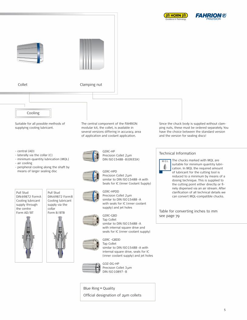
Collet Clamping nut
Cooling
Suitable for all possible methods of supplying cooling lubricant.
The central component of the FAHRION modular kit, the collet, is available in several versions differing in accuracy, area of application and coolant application.
Since the chuck body is supplied without clam-ping nuts, these must be ordered separately. You have the choice between the standard version and the version for sealing discs!
- central (AD)- laterally via the collar (C)- minimum-quantity lubrication (MQL)- air cooling- peripheral cooling along the shaft by
means of larger sealing disc
GERC-HPPrecision Collet 2 µmDIN ISO 15488 - B (ER/ESX)
GERC-HPDPrecision Collet 2 µmsimilar to DIN ISO 15488 - A with Seals for IC (Inner Coolant Supply)
GERC-HPDDPrecision Collet 2 µmsimilar to DIN ISO 15488 - Awith seals for IC (inner coolant supply) and jet holes
GERC-GBDTap Colletsimilar to DIN ISO 15488 - Awith internal square drive and seals for IC (inner coolant supply)
GERC -GBDDTap Collet similar to DIN ISO 15488 - A with internal square drive, seals for IC (inner coolant supply) and jet holes
GOZ-DG-HPPrecision Collet 3 µmDIN ISO 10897 - B
Technical Information
Table for converting inches to mmsee page 79
The chucks marked with MQL are suitable for minimum quantity lubri-cation. In MQL the required amount of lubricant for the cutting tool is reduced to a minimum by means of a dosing technique. This is supplied to the cutting point either directly or £ -nely dispersed via an air stream. After clari£ cation of all technical details we can convert MQL-compatible chucks.
Pull StudDIN 69872 Form ACooling lubricant supply through the centre Form AD / BT
Pull StudDIN 69872 Form BCooling lubricant supply via the collar Form B / BTB
- slim version for HPCM Mini Clamping Nuts- small interference contour- External diameter of clamping nuts 10 / 16 / 22 mm- Clamping ranges 1 – 5 mm (GERC8), 1 – 7 mm (GERC11),
1 – 10 mm (GERC16)- Standard projection lengths (dimension A) of 50 / 70 /
75 / 90 / 100 / 120 / 4“ / 130 / 6“ / 150 / 160 mm (type-dependent)
Application examples: HSC machining, die and mold making, medical and dental technology, drilling / reaming /£ nishing
- tapered version for HPCC Special Clamping Nuts- small interference contour with External diameter of
clamping nuts 16 / 22 / 24 mm- Clamping ranges 1 – 7 mm (GERC11), 1 – 10 mm (GERC16)- Standard projection lengths (dimension A) of 45 / 55 /
60 / 100 / 4“ / 130 / 6“ / 160 mm (type-dependent)Application examples: HSC machining, model, mold and tool making, drilling / reaming / £ nishing and roughing
- rigid version for HPC Standard Clamping Nuts- External diameter of clamping nuts 30 / 32 / 40 / 50 / 63 mm- Clamping ranges 1 – 10 mm (GERC16), 1 – 13 mm
(GERC20), 1 – 16 mm (GERC25), 2 – 20 mm (GERC32), 3 – 26 mm (GERC40), 2 – 25 mm (FM25DG), 4 – 32 mm (FM32DG)
- standard projection lengths (dimension A) of 40 / 48 / 50 / 60 / 2,5“ / 70 / 75 / 3“ / 80 / 85 / 90 / 100 / 105 / 4“ / 120 / 5“ / 130 / 135 / 6“ / 150 / 160 / 165 / / / 200 mm (type-dependent)Application examples: HSC and HPC machining, model, mold and tool making, drilling / reaming /£ nishing / roughing, machining of wood
M Q L
Blue Ring = Quality
Of£ cial designation of 2µm collets
6 FAHRION || Tool clamping systems
Straight.
The direct way to success: Due to a uniquely clear and speci� c design, supreme production quality and consistent service orien-tation, FAHRION makes your work easier, more ef� cient, faster and more precise with its comprehensive range of tool clamping systems. Just right for demanding production tasks.
7
For decades, FAHRION has been following an uncompromi-sing line, when it comes to supporting your work: All FAHRION products and services are directed to convince with maximum functionality and application orientation – at an excellent price-performance ratio.
In terms of quality, FAHRION products offer performance values already in the standard product range which for other producers are limited to expensive premium series. Our DIN ISO 15488 (ER/ESX) and DIN ISO 10897 (OZ) based precision collets are produced with tolerance values which lie signi£cantly below the required DIN norm.
Together with the patented FAHRION precision collet chuck CENTRO|P and other high performance system components, our collets form a perfectly integrated complete system which guarantees maximum precision, stability, ¸exibility, reliability and cost effectiveness.
At the same time FAHRION is a manufacturer which con-tinuously and critically monitors and optimizes its product portfolio – therefore, FAHRION technology brings you the maximum possible bene£t at any time and with every order.
Close to your demands: Every detail is optimized for maximum functionality.
8 FAHRION || Tool clamping systems
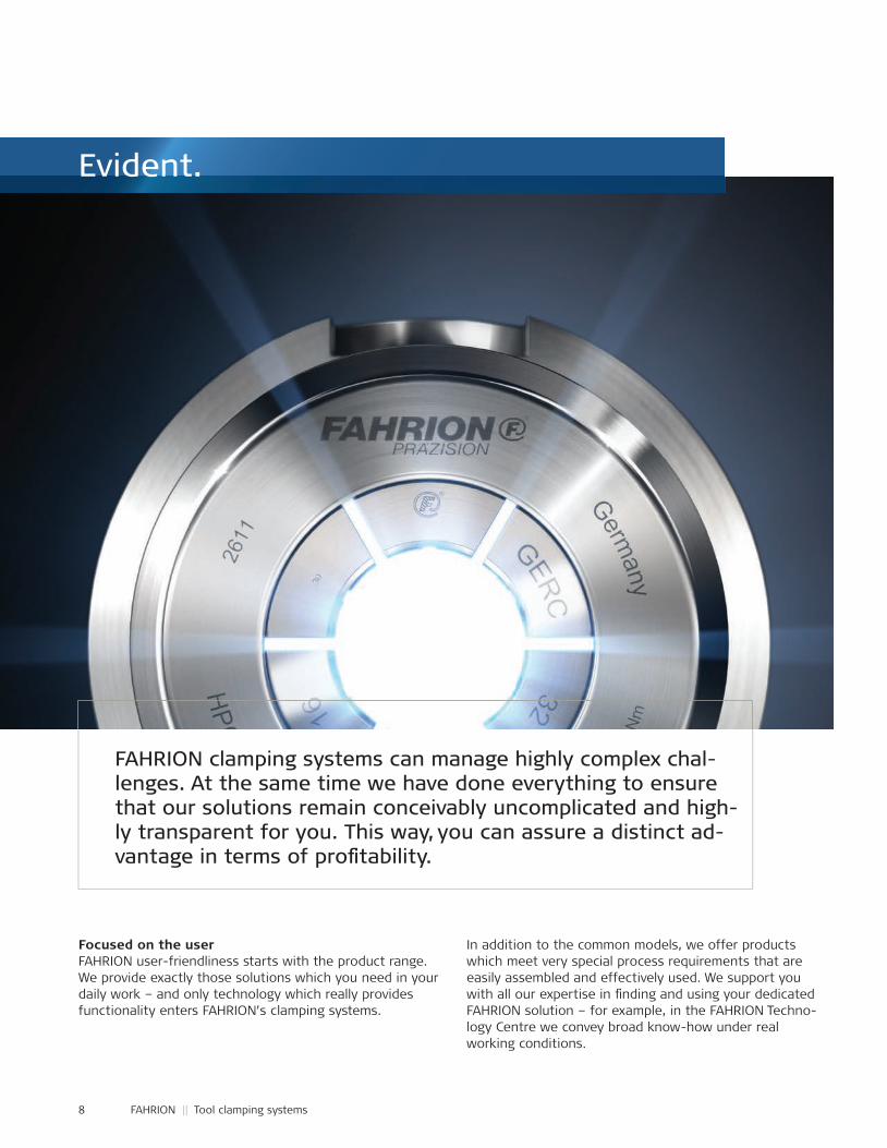
FAHRION clamping systems can manage highly complex chal-lenges. At the same time we have done everything to ensurethat our solutions remain conceivably uncomplicated and high-ly transparent for you. This way, you can assure a distinct ad-vantage in terms of pro� tability.
Focused on the userFAHRION user-friendliness starts with the product range. We provide exactly those solutions which you need in your daily work – and only technology which really provides functionality enters FAHRION’s clamping systems.
In addition to the common models, we offer products which meet very special process requirements that are easily assembled and effectively used. We support you with all our expertise in £ nding and using your dedicated FAHRION solution – for example, in the FAHRION Techno-logy Centre we convey broad know-how under real working conditions.
Evident.
9
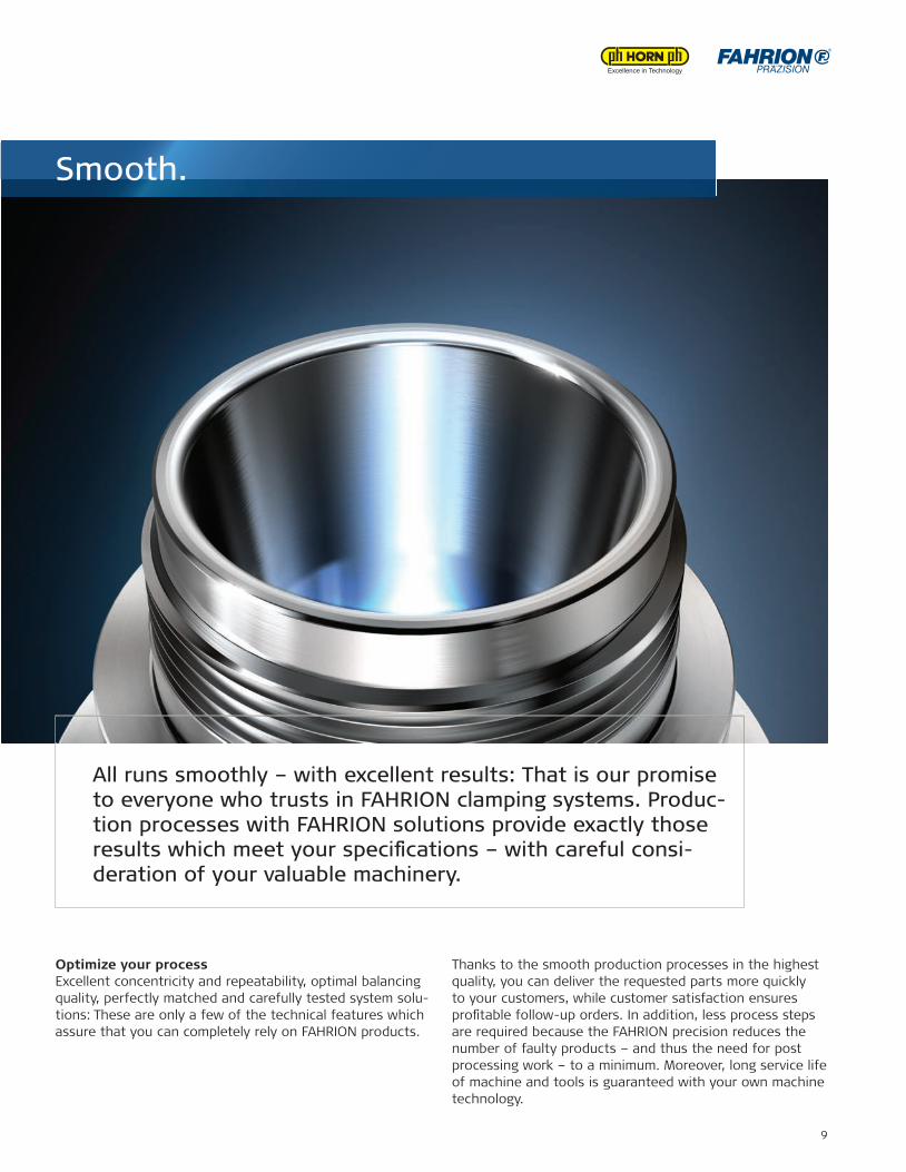
Optimize your processExcellent concentricity and repeatability, optimal balancing quality, perfectly matched and carefully tested system solu-tions: These are only a few of the technical features which assure that you can completely rely on FAHRION products.
Thanks to the smooth production processes in the highest quality, you can deliver the requested parts more quickly to your customers, while customer satisfaction ensures pro£ table follow-up orders. In addition, less process steps are required because the FAHRION precision reduces the number of faulty products – and thus the need for post processing work – to a minimum. Moreover, long service life of machine and tools is guaranteed with your own machine technology.
All runs smoothly – with excellent results: That is our promise to everyone who trusts in FAHRION clamping systems. Produc-tion processes with FAHRION solutions provide exactly those results which meet your speci� cations – with careful consi-deration of your valuable machinery.
Smooth.
10 FAHRION || Tool clamping systems
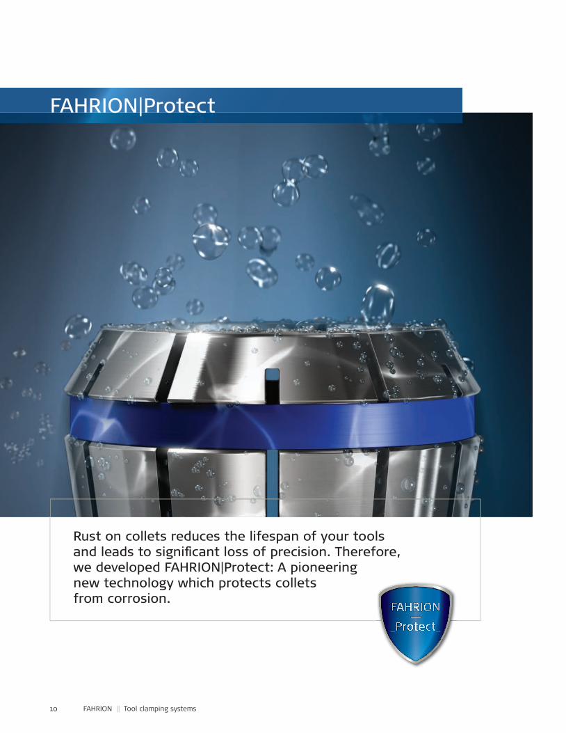
Rust on collets reduces the lifespan of your tools and leads to signi� cant loss of precision. Therefore, we developed FAHRION|Protect: A pioneering new technology which protects collets from corrosion.
FAHRION|Protect
11
FAHRION|Protect goes beyond all standards that you know in corrosion protection of clamping tools. Many clamping tools are not protected at all. With others, the corrosionprotection is limited to the visible areas only. Or with cutting tools with insert pockets, only an accuracy of about 0.01 mm is required.
FAHRION is the £rst manufacturer to offer a coating of the functional surfaces in the µ-range – over its complete and £nely tuned product range. FAHRION|Protect conserves FAHRION collets effectively from external in¸uences and preserves their functionality and precision for a longer time. That is how FAHRION shows once again in an impres-sive way how advanced technology can be brought to the market as an integrated customer solution.
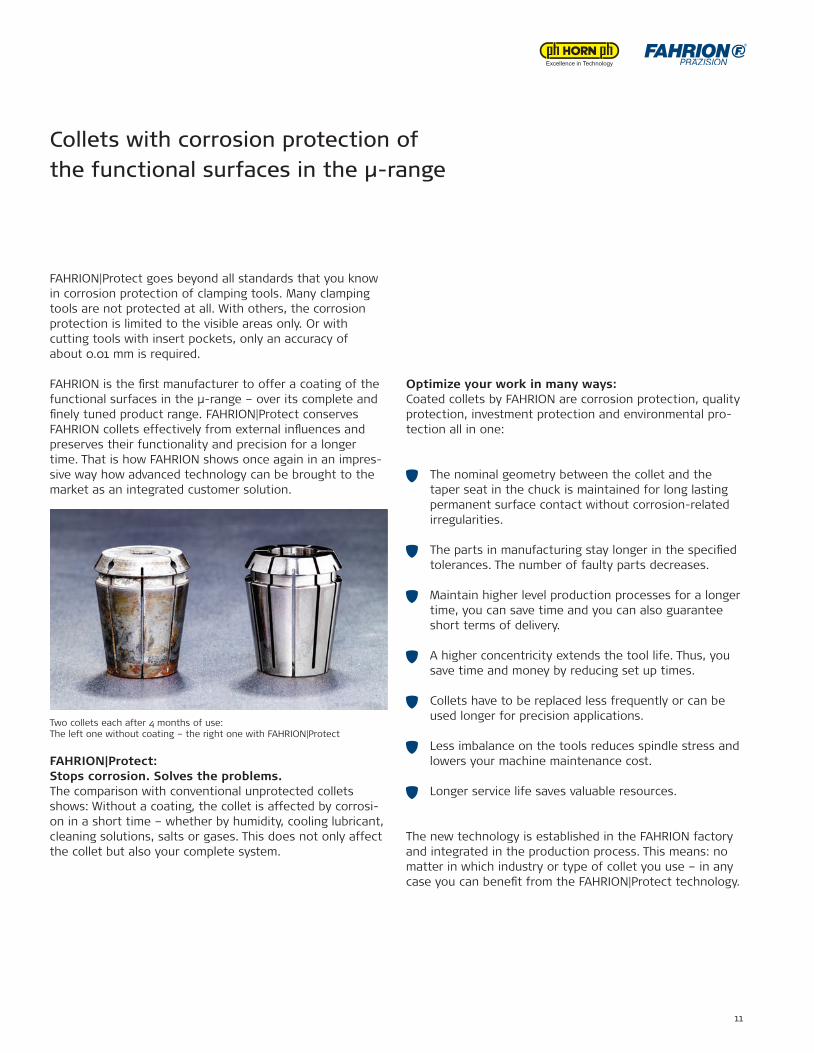
FAHRION|Protect: Stops corrosion. Solves the problems.The comparison with conventional unprotected collets shows: Without a coating, the collet is affected by corrosi-on in a short time – whether by humidity, cooling lubricant, cleaning solutions, salts or gases. This does not only affect the collet but also your complete system.
Optimize your work in many ways: Coated collets by FAHRION are corrosion protection, quality protection, investment protection and environmental pro-tection all in one:
The nominal geometry between the collet and the taper seat in the chuck is maintained for long lasting permanent surface contact without corrosion-related irregularities.
The parts in manufacturing stay longer in the speci£ed tolerances. The number of faulty parts decreases.
Maintain higher level production processes for a longer time, you can save time and you can also guarantee short terms of delivery.
A higher concentricity extends the tool life. Thus, you save time and money by reducing set up times.
Collets have to be replaced less frequently or can be used longer for precision applications.
Less imbalance on the tools reduces spindle stress and lowers your machine maintenance cost.
Longer service life saves valuable resources.
The new technology is established in the FAHRION factory and integrated in the production process. This means: no matter in which industry or type of collet you use – in any case you can bene£t from the FAHRION|Protect technology.
Collets with corrosion protection of the functional surfaces in the µ-range
Two collets each after 4 months of use: The left one without coating – the right one with FAHRION|Protect
12 FAHRION || Tool clamping systems
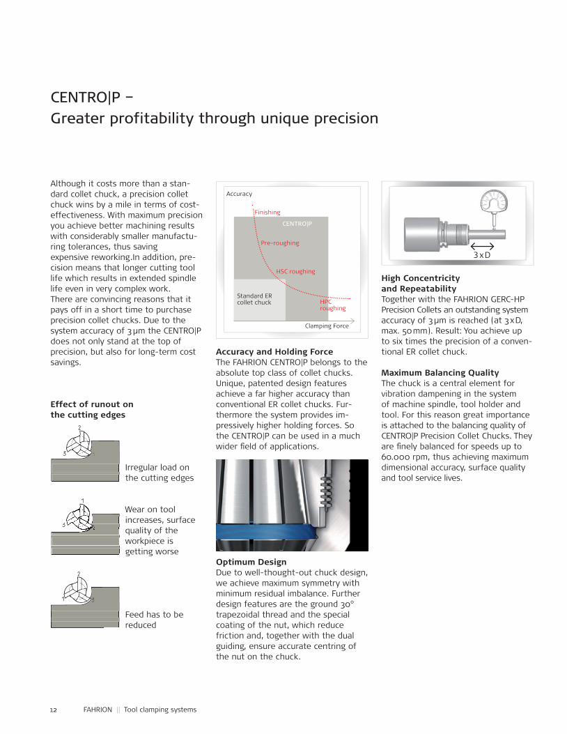
Although it costs more than a stan-dard collet chuck, a precision collet chuck wins by a mile in terms of cost-effectiveness. With maximum precision you achieve better machining results with considerably smaller manufactu-ring tolerances, thus saving expensive reworking.In addition, pre-cision means that longer cutting tool life which results in extended spindle life even in very complex work. There are convincing reasons that it pays off in a short time to purchase precision collet chucks. Due to the system accuracy of 3 µm the CENTRO|P does not only stand at the top of precision, but also for long-term cost savings.
Effect of runout on the cutting edges
Irregular load on the cutting edges
Wear on tool increases, surface quality of the workpiece is getting worse
Feed has to be reduced
Accuracy and Holding ForceThe FAHRION CENTRO|P belongs to the absolute top class of collet chucks.Unique, patented design features achieve a far higher accuracy than conventional ER collet chucks. Fur-thermore the system provides im-pressively higher holding forces. So the CENTRO|P can be used in a much wider £ eld of applications.
Optimum DesignDue to well-thought-out chuck design, we achieve maximum symmetry with minimum residual imbalance. Further design features are the ground 30° trapezoidal thread and the special coating of the nut, which reduce friction and, together with the dual guiding, ensure accurate centring of the nut on the chuck.
High Concentricity and RepeatabilityTogether with the FAHRION GERC-HPPrecision Collets an outstanding system accuracy of 3 μm is reached (at 3 x D, max. 50 mm). Result: You achieve up to six times the precision of a conven-tional ER collet chuck.
Maximum Balancing QualityThe chuck is a central element for vibration dampening in the system of machine spindle, tool holder and tool. For this reason great importance is attached to the balancing quality of CENTRO|P Precision Collet Chucks. They are £ nely balanced for speeds up to 60.000 rpm, thus achieving maximum dimensional accuracy, surface quality and tool service lives.
CENTRO|P – Greater profitability through unique precision
3 x D
Clamping Force
Accuracy
Finishing
Pre-roughing
HSC roughing
HPCroughing
Standard ERcollet chuck
CENTRO|P
Irregular load on the cutting edges Irregular load on the cutting edges
Wear on tool increases, surface quality of the workpiece is getting worse
Wear on tool increases, surface Wear on tool Wear on tool increases, surface Wear on tool Wear on tool Wear on tool increases, surface increases, surface quality of the workpiece is getting worse
increases, surface increases, surface increases, surface increases, surface increases, surface increases, surface increases, surface quality of the increases, surface increases, surface increases, surface quality of the
Feed has to be reduced Feed has to be reduced reduced
13
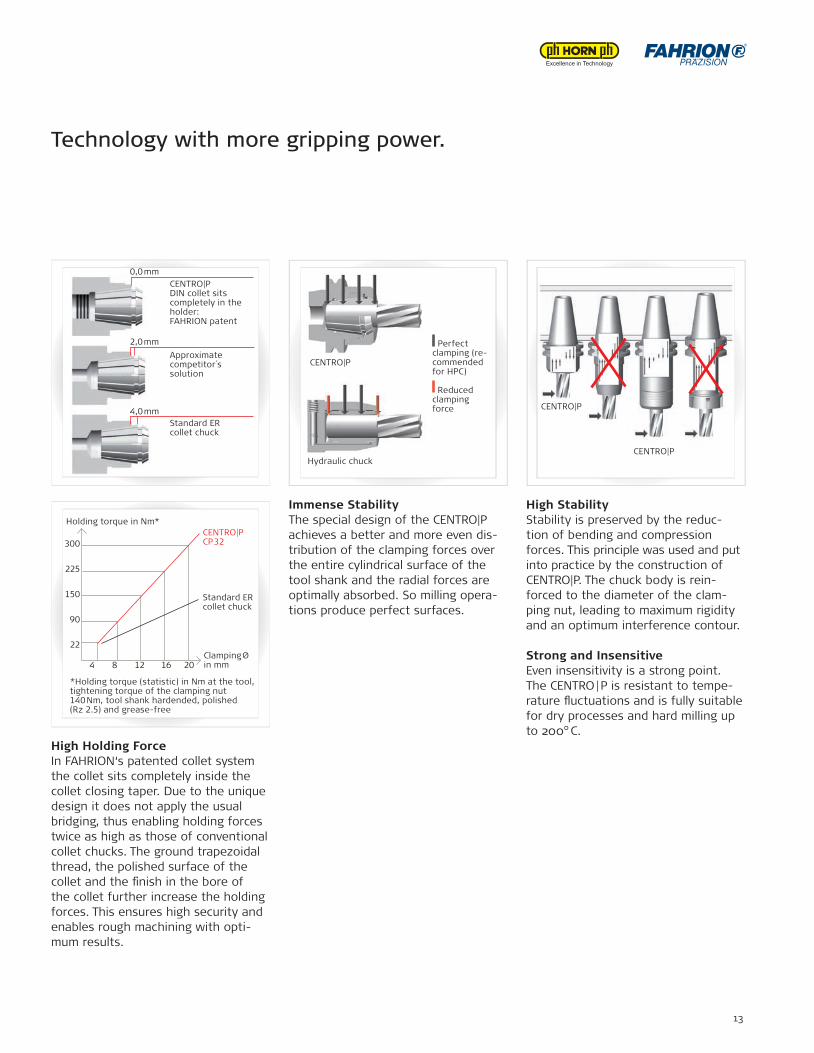
High Holding ForceIn FAHRION‘s patented collet system the collet sits completely inside the collet closing taper. Due to the unique design it does not apply the usual bridging, thus enabling holding forces twice as high as those of conventional collet chucks. The ground trapezoidal thread, the polished surface of the collet and the £ nish in the bore of the collet further increase the holding forces. This ensures high security and enables rough machining with opti-mum results.
Immense StabilityThe special design of the CENTRO|P achieves a better and more even dis-tribution of the clamping forces over the entire cylindrical surface of the tool shank and the radial forces are optimally absorbed. So milling opera-tions produce perfect surfaces.
High StabilityStability is preserved by the reduc-tion of bending and compression forces. This principle was used and put into practice by the construction of CENTRO|P. The chuck body is rein-forced to the diameter of the clam-ping nut, leading to maximum rigidity and an optimum interference contour.
Strong and InsensitiveEven insensitivity is a strong point.The CENTRO | P is resistant to tempe-rature ̧uctuations and is fully suitable for dry processes and hard milling up to 200° C.
Technology with more gripping power.
4,0 mm
0,0 mm
2,0 mm
CENTRO|PDIN collet sitscompletely in the holder:FAHRION patent
Approximatecompetitor´ssolution
Standard ER collet chuck
CENTRO|P CP 32300
225
150
90
22
4 8 12 16 20
*Holding torque (statistic) in Nm at the tool,tightening torque of the clamping nut 140 Nm, tool shank hardended, polished(Rz 2.5) and grease-free
Standard ERcollet chuck
Clamping Øin mm
Holding torque in Nm*
CENTRO|P
Hydraulic chuck
Perfectclamping (re-commendedfor HPC)
Reducedclamping force CENTRO|P
CENTRO|P
14 FAHRION || Tool clamping systems
System intelligence in every detail
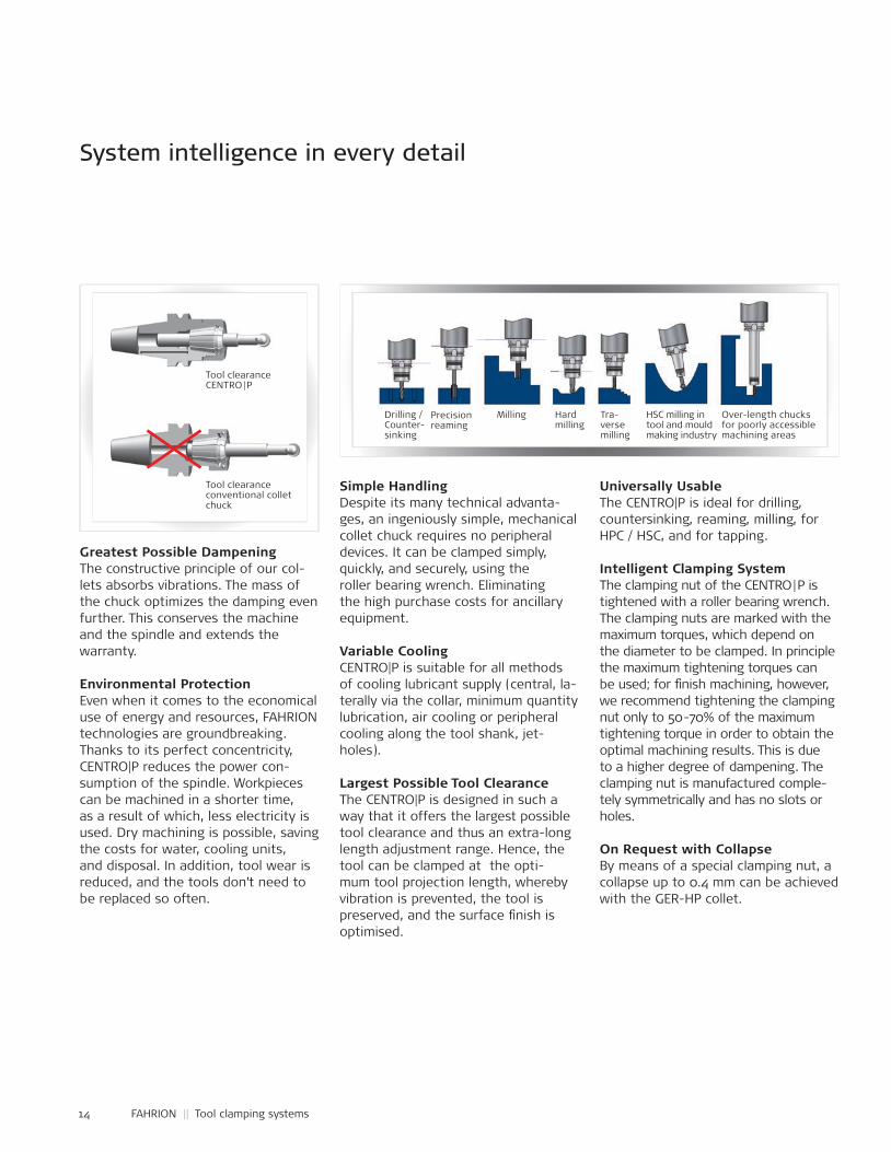
Over-length chucks for poorly accessible machining areas
Tra-verse milling
HSC milling in tool and mould making industry
Milling Hard milling
Precision reaming
Drilling /Counter-sinking
Greatest Possible DampeningThe constructive principle of our col-lets absorbs vibrations. The mass of the chuck optimizes the damping even further. This conserves the machineand the spindle and extends the warranty.
Environmental ProtectionEven when it comes to the economical use of energy and resources, FAHRIONtechnologies are groundbreaking. Thanks to its perfect concentricity, CENTRO|P reduces the power con-sumption of the spindle. Workpieces can be machined in a shorter time, as a result of which, less electricity is used. Dry machining is possible, saving the costs for water, cooling units, and disposal. In addition, tool wear is reduced, and the tools don’t need to be replaced so often.
Simple HandlingDespite its many technical advanta-ges, an ingeniously simple, mechanical collet chuck requires no peripheral devices. It can be clamped simply, quickly, and securely, using the roller bearing wrench. Eliminating the high purchase costs for ancillary equipment.
Variable CoolingCENTRO|P is suitable for all methods of cooling lubricant supply (central, la-terally via the collar, minimum quantity lubrication, air cooling or peripheral cooling along the tool shank, jet-holes).
Largest Possible Tool ClearanceThe CENTRO|P is designed in such a way that it offers the largest possible tool clearance and thus an extra-long length adjustment range. Hence, the tool can be clamped at the opti-mum tool projection length, whereby vibration is prevented, the tool is preserved, and the surface £nish is optimised.
Universally UsableThe CENTRO|P is ideal for drilling, countersinking, reaming, milling, for HPC / HSC, and for tapping.
Intelligent Clamping SystemThe clamping nut of the CENTRO | P is tightened with a roller bearing wrench. The clamping nuts are marked with the maximum torques, which depend on the diameter to be clamped. In principle the maximum tightening torques can be used; for £nish machining, however, we recommend tightening the clamping nut only to 50-70% of the maximum tightening torque in order to obtain the optimal machining results. This is due to a higher degree of dampening. The clamping nut is manufactured comple-tely symmetrically and has no slots or holes.
On Request with CollapseBy means of a special clamping nut, a collapse up to 0.4 mm can be achieved with the GER-HP collet.
Tool clearance CENTRO | P
Tool clearanceconventional collet chuck
15
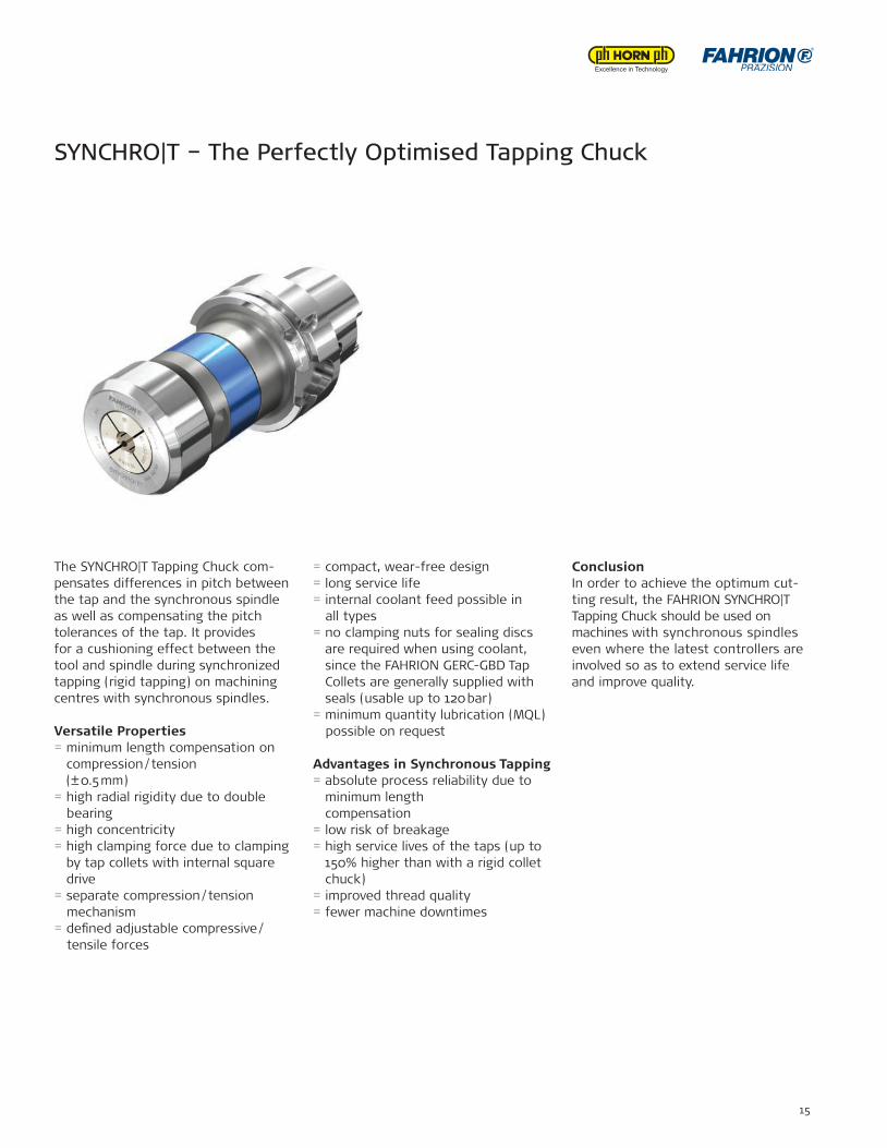
SYNCHRO|T – The Perfectly Optimised Tapping Chuck
The SYNCHRO|T Tapping Chuck com-pensates differences in pitch between the tap and the synchronous spindle as well as compensating the pitch tolerances of the tap. It provides for a cushioning effect between the tool and spindle during synchronized tapping (rigid tapping) on machining centres with synchronous spindles.
Versatile Properties= minimum length compensation on
compression / tension (± 0.5 mm)
= high radial rigidity due to double bearing= high concentricity= high clamping force due to clamping
by tap collets with internal square drive
= separate compression / tension mechanism= de£ned adjustable compressive / tensile forces
= compact, wear-free design= long service life= internal coolant feed possible in all types= no clamping nuts for sealing discs
are required when using coolant, since the FAHRION GERC-GBD Tap Collets are generally supplied with seals (usable up to 120 bar)
= minimum quantity lubrication (MQL) possible on request
Advantages in Synchronous Tapping= absolute process reliability due to
minimum length compensation
= low risk of breakage= high service lives of the taps (up to
150% higher than with a rigid collet chuck)
= improved thread quality= fewer machine downtimes
ConclusionIn order to achieve the optimum cut-ting result, the FAHRION SYNCHRO|T Tapping Chuck should be used on machines with synchronous spindles even where the latest controllers are involved so as to extend service life and improve quality.
16 FAHRION || Tool clamping systems
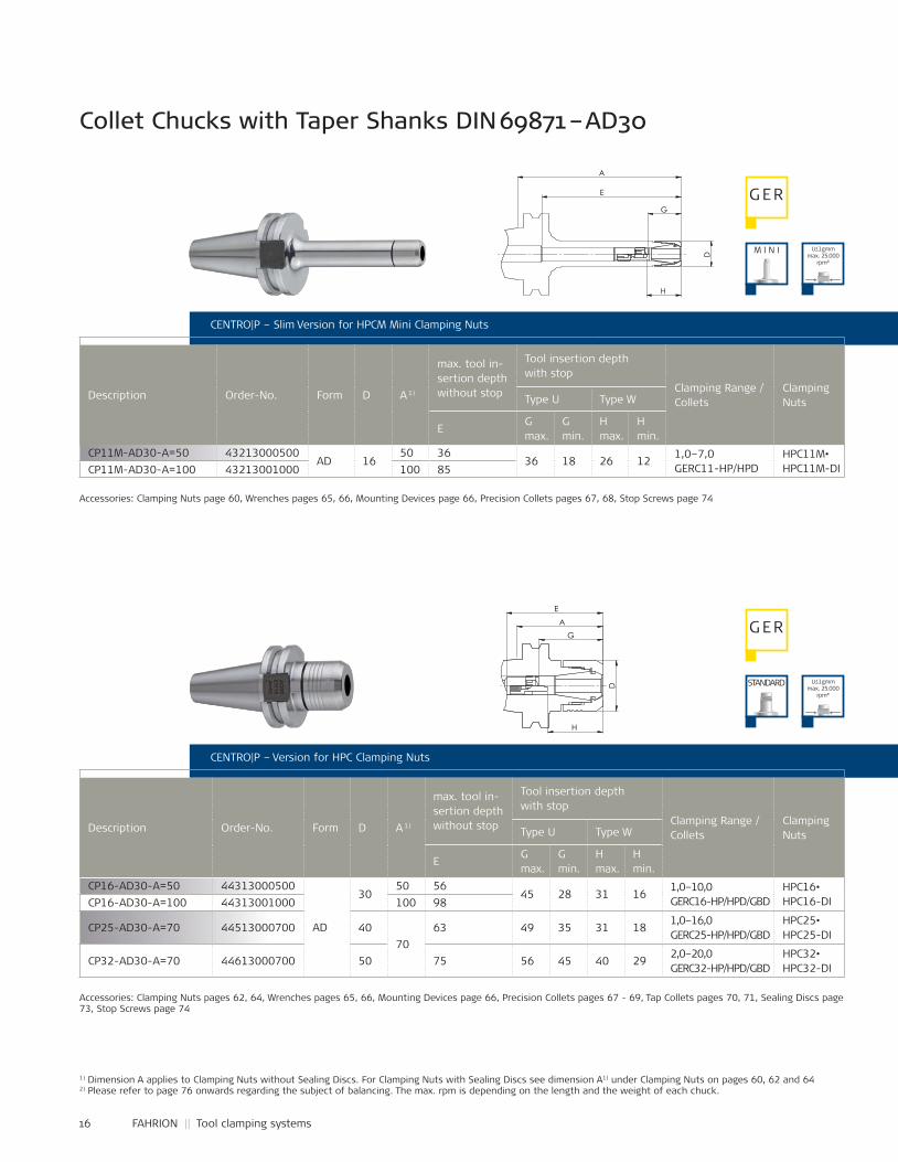
CP11M-AD30-A=50 43213000500AD 16
50 3636 18 26 12
1,0–7,0 GERC11-HP/HPD
HPC11M• HPC11M-DICP11M-AD30-A=100 43213001000 100 85
CP16-AD30-A=50 44313000500
AD
3050 56
45 28 31 161,0–10,0 GERC16-HP/HPD/GBD
HPC16• HPC16-DICP16-AD30-A=100 44313001000 100 98
CP25-AD30-A=70 44513000700 4070
63 49 35 31 181,0–16,0 GERC25-HP/HPD/GBD
HPC25• HPC25-DI
CP32-AD30-A=70 44613000700 50 75 56 45 40 292,0–20,0 GERC32-HP/HPD/GBD
HPC32• HPC32-DI
Collet Chucks with Taper Shanks DIN 69871 – AD30
CENTRO|P – Slim Version for HPCM Mini Clamping Nuts
Description Order-No. Form D A 1)
max. tool in-sertion depth without stop
Tool insertion depth with stop
Clamping Range / Collets
ClampingNutsType U Type W
EG max.
G min.
H max.
H min.
Accessories: Clamping Nuts page 60, Wrenches pages 65, 66, Mounting Devices page 66, Precision Collets pages 67, 68, Stop Screws page 74
Accessories: Clamping Nuts pages 62, 64, Wrenches pages 65, 66, Mounting Devices page 66, Precision Collets pages 67 - 69, Tap Collets pages 70, 71, Sealing Discs page 73, Stop Screws page 74
1) Dimension A applies to Clamping Nuts without Sealing Discs. For Clamping Nuts with Sealing Discs see dimension A1) under Clamping Nuts on pages 60, 62 and 642) Please refer to page 76 onwards regarding the subject of balancing. The max. rpm is depending on the length and the weight of each chuck.
CENTRO|P – Version for HPC Clamping Nuts
Description Order-No. Form D A 1)
max. tool in-sertion depth without stop
Tool insertion depth with stop
Clamping Range / Collets
ClampingNutsType U Type W
EG max.
G min.
H max.
H min.
G ER
U≤1gmm max. 25.000
rpm²)
U≤1gmm max. 25.000
rpm²)
M I N I
G ER
STANDARD
H
G
E
A
D
G
H
D
A
E
17
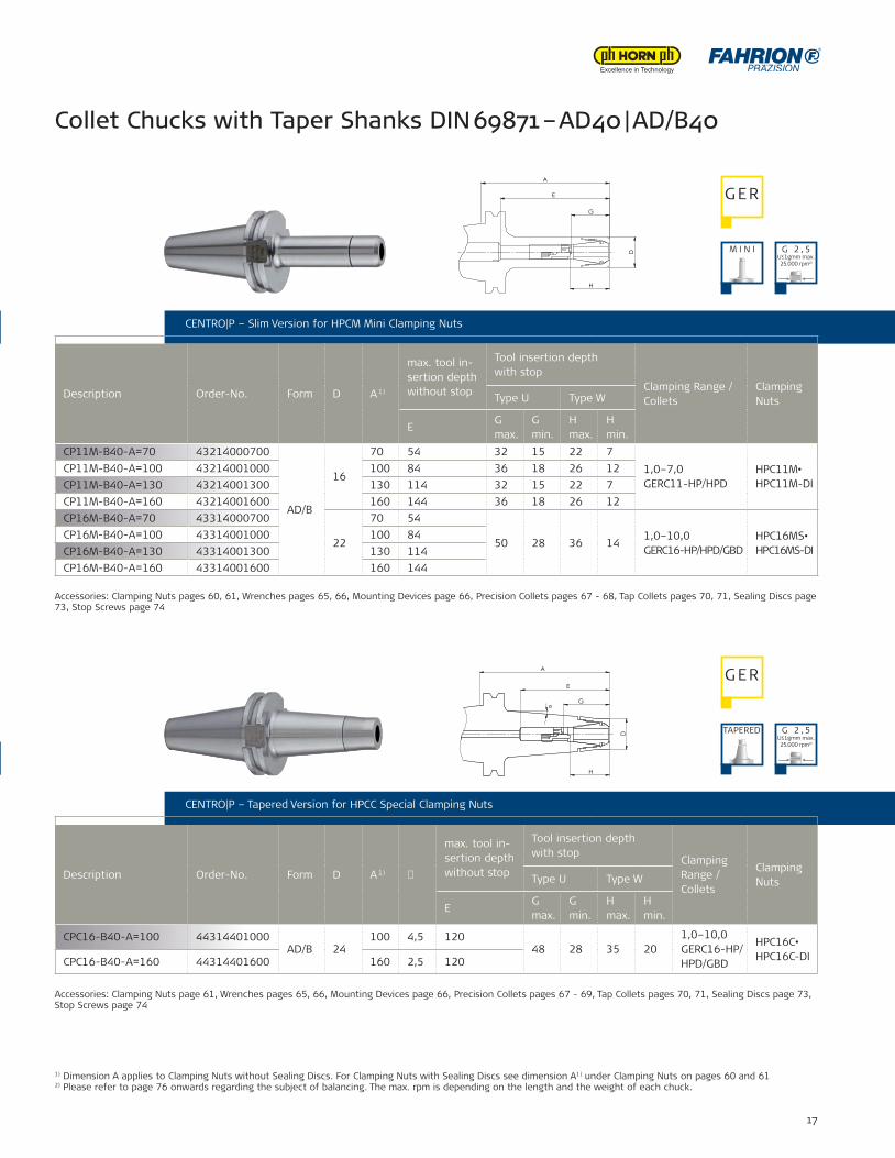
CP11M-B40-A=70 43214000700
AD/B
16
70 54 32 15 22 71,0–7,0 GERC11-HP/HPD
HPC11M• HPC11M-DI
CP11M-B40-A=100 43214001000 100 84 36 18 26 12CP11M-B40-A=130 43214001300 130 114 32 15 22 7CP11M-B40-A=160 43214001600 160 144 36 18 26 12CP16M-B40-A=70 43314000700
22
70 54
50 28 36 141,0–10,0 GERC16-HP/HPD/GBD
HPC16MS• HPC16MS-DI
CP16M-B40-A=100 43314001000 100 84CP16M-B40-A=130 43314001300 130 114CP16M-B40-A=160 43314001600 160 144
CPC16-B40-A=100 44314401000AD/B 24
100 4,5 12048 28 35 20
1,0–10,0GERC16-HP/HPD/GBD
HPC16C•HPC16C-DICPC16-B40-A=160 44314401600 160 2,5 120
Collet Chucks with Taper Shanks DIN 69871 – AD40 | AD/B40
CENTRO|P – Slim Version for HPCM Mini Clamping Nuts
CENTRO|P – Version for HPC Clamping Nuts
CENTRO|P – Slim Version for HPCM Mini Clamping Nuts
Description Order-No. Form D A 1)
max. tool in-sertion depth without stop
Tool insertion depth with stop
Clamping Range / Collets
ClampingNutsType U Type W
EG max.
G min.
H max.
H min.
CENTRO|P – Tapered Version for HPCC Special Clamping Nuts
Description Order-No. Form D A 1) �
max. tool in-sertion depth without stop
Tool insertion depth with stop
Clamping Range / Collets
ClampingNutsType U Type W
EG max.
G min.
H max.
H min.
Accessories: Clamping Nuts pages 60, 61, Wrenches pages 65, 66, Mounting Devices page 66, Precision Collets pages 67 - 68, Tap Collets pages 70, 71, Sealing Discs page 73, Stop Screws page 74
Accessories: Clamping Nuts page 61, Wrenches pages 65, 66, Mounting Devices page 66, Precision Collets pages 67 - 69, Tap Collets pages 70, 71, Sealing Discs page 73, Stop Screws page 74
1) Dimension A applies to Clamping Nuts without Sealing Discs. For Clamping Nuts with Sealing Discs see dimension A1) under Clamping Nuts on pages 60 and 612) Please refer to page 76 onwards regarding the subject of balancing. The max. rpm is depending on the length and the weight of each chuck.
G ER
G ER
G 2 , 5U≤1gmm max. 25.000 rpm²)
G 2 , 5U≤1gmm max. 25.000 rpm²)
M I N I
TAPERED
H
D
G
A
E
A
D
E
H
G α
18 FAHRION || Tool clamping systems
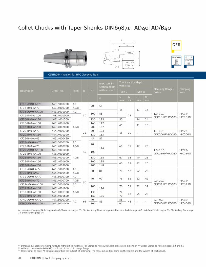
CP16-AD40-A=70 44315000700 AD
30
70 5545
28
31 161,0–10,0GERC16-HP/HPD/GBD
HPC16•HPC16-DI
CP16-B40-A=70 44314000700 AD/BCP16-AD40-A=100 44315001000 AD
100 85CP16-B40-A=100 44314001000
AD/B
CP16-B40-A=130 44314001300 130 115 50 34 14CP16-B40-A=160 44314001600 160 117
45 31 16CP16-B40-A=200 44314002000 200 157CP20-B40-A=70 44414000700
3270 103
48 31 - -1,0–13,0GERC20-HP/HPD/GBD
HPC20•HPC20-DICP20-B40-A=130 44414001300 130 163
CP25-B40-A=45 44514000450
40
45 87
60 35 42 201,0–16,0GERC25-HP/HPD/GBD
HPC25•HPC25-DI
CP25-AD40-A=70 44515000700 AD70
114CP25-B40-A=70 44514000700 AD/BCP25-AD40-A=100 44515001000
AD/B
100CP25-B40-A=100 44514001000CP25-B40-A=130 44514001300 130 138 67 38 49 21CP25-B40-A=160 44514001600 160 118
60 35 42 20CP25-B40-A=200 44514002000 200 148CP32-AD40-A=50 44615000500 AD
50
50 84 70 52 52 26
2,0–20,0GERC32-HP/HPD/GBD
HPC32•HPC32-DI
CP32-B40-A=50 44614000500 AD/BCP32-AD40-A=70 44615000700 AD
70 99 75 55 62 42CP32-B40-A=70 44614000700 AD/BCP32-AD40-A=100 44615001000 AD
100114
70 52 52 32CP32-B40-A=100 44614001000
AD/BCP32-B40-A=130 44614001300 130 7442 55 28
CP32-B40-A=160 44614001600 160 135 70CP40-AD40-A=70 2) 44715000700
AD 6370
8355
48 - -3,0–26,0GERC40-HP/HPD/GBD
HPC40•HPC40-DICP40-AD40-A=100 2) 44715001000 100 62
Collet Chucks with Taper Shanks DIN 69871 – AD40 | AD/B40
CENTRO|P – Version for HPC Clamping Nuts
Description Order-No. Form D A 1)
max. tool in-sertion depth without stop
Tool insertion depth with stop
Clamping Range / Collets
ClampingNutsType U Type W
EG max.
G min.
H max.
H min.
Accessories: Clamping Nuts pages 62, 64, Wrenches pages 65, 66, Mounting Devices page 66, Precision Collets pages 67 - 69, Tap Collets pages 70, 71, Sealing Discs page 73, Stop Screws page 74
1) Dimension A applies to Clamping Nuts without Sealing Discs. For Clamping Nuts with Sealing Discs see dimension A1) under Clamping Nuts on pages 62 and 642) Without clearance to DIN 69871 in front of the tool change ¸ange3) Please refer to page 76 onwards regarding the subject of balancing. The max. rpm is depending on the length and the weight of each chuck.
STANDARD
G ER
G 2 , 5U≤1gmm max. 25.000 rpm³)
D
G
H
A
E
Name:±0,06
±0,1
±0,2
±0,3
±0,5
±1,0
44614000700Artikel-Nr.:
Artikel-Bez. 2:Gez.Gepr.Gen.
RohteilNr.
Kanten 0,3x45°gebrochen
Passmaß Abmaß
Maßstab:
1:1
-10
10-30
30-80
80-180
180-500
500-1000
zul.Abweichg.n.tol.bearb.Maße:
Werkstoff:
Datum:05.11.11 Ca
SapnnzangenfutterCP32-B40-A=70
verg. auf:Einsatztiefe:
Wärmebehandlung:
angelassen auf:
Gewicht:
05.0
9.20
11 -
K:\S
W-A
WU
\Mod
elle
\CP-
Futt
er\Z
usam
men
stel
lung
en\C
P32\
Kata
logz
eich
n\44
6140
0070
0-K
19
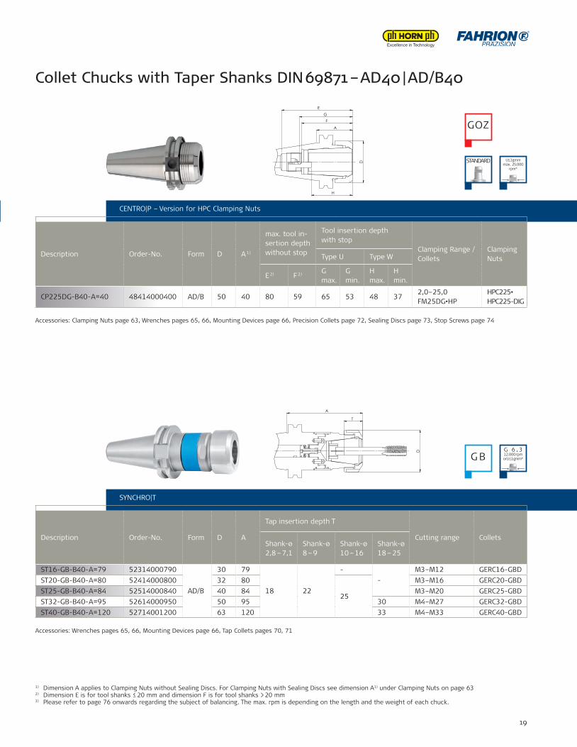
CP225DG-B40-A=40 48414000400 AD/B 50 40 80 59 65 53 48 372,0–25,0FM25DG•HP
HPC225•HPC225-DIG
ST16-GB-B40-A=79 52314000790
AD/B
30 79
18 22
--
M3–M12 GERC16-GBDST20-GB-B40-A=80 52414000800 32 80
25
M3–M16 GERC20-GBDST25-GB-B40-A=84 52514000840 40 84 M3–M20 GERC25-GBDST32-GB-B40-A=95 52614000950 50 95 30 M4–M27 GERC32-GBDST40-GB-B40-A=120 52714001200 63 120 33 M4–M33 GERC40-GBD
Collet Chucks with Taper Shanks DIN 69871 – AD40 | AD/B40
CENTRO|P – Version for HPC Clamping Nuts CENTRO|P – Version for HPC Clamping Nuts
Description Order-No. Form D A 1)
max. tool in-sertion depth without stop
Tool insertion depth with stop
Clamping Range / Collets
ClampingNutsType U Type W
E 2) F 2) G max.
G min.
H max.
H min.
SYNCHRO|T
Description Order-No. Form D A
Tap insertion depth T
Cutting range ColletsShank-ø2,8 – 7,1
Shank-ø8 – 9
Shank-ø10 – 16
Shank-ø18 – 25
1) Dimension A applies to Clamping Nuts without Sealing Discs. For Clamping Nuts with Sealing Discs see dimension A1) under Clamping Nuts on page 632) Dimension E is for tool shanks ≤ 20 mm and dimension F is for tool shanks > 20 mm3) Please refer to page 76 onwards regarding the subject of balancing. The max. rpm is depending on the length and the weight of each chuck.
Accessories: Wrenches pages 65, 66, Mounting Devices page 66, Tap Collets pages 70, 71
Accessories: Clamping Nuts page 63, Wrenches pages 65, 66, Mounting Devices page 66, Precision Collets page 72, Sealing Discs page 73, Stop Screws page 74
STANDARD
GOZ
G BG 6 , 312.000 rpmorU ≤ 1 gmm³)
U≤1gmm max. 25.000
rpm³)
D
A
G
H
E
F
T
A
D
20 FAHRION || Tool clamping systems
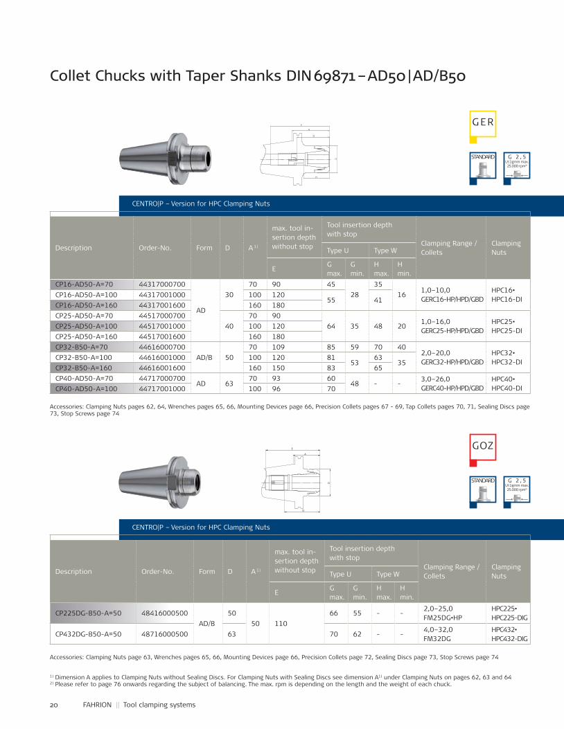
CP16-AD50-A=70 44317000700
AD
3070 90 45
2835
161,0–10,0GERC16-HP/HPD/GBD
HPC16•HPC16-DICP16-AD50-A=100 44317001000 100 120
55 41CP16-AD50-A=160 44317001600 160 180CP25-AD50-A=70 44517000700
4070 90
64 35 48 201,0–16,0GERC25-HP/HPD/GBD
HPC25•HPC25-DI
CP25-AD50-A=100 44517001000 100 120CP25-AD50-A=160 44517001600 160 180CP32-B50-A=70 44616000700
AD/B 5070 109 85 59 70 40
2,0–20,0GERC32-HP/HPD/GBD
HPC32•HPC32-DI
CP32-B50-A=100 44616001000 100 120 8153
6335
CP32-B50-A=160 44616001600 160 150 83 65CP40-AD50-A=70 44717000700
AD 6370 93 60
48 - -3,0–26,0GERC40-HP/HPD/GBD
HPC40•HPC40-DICP40-AD50-A=100 44717001000 100 96 70
CP225DG-B50-A=50 48416000500AD/B
5050 110
66 55 - -2,0–25,0FM25DG•HP
HPC225•HPC225-DIG
CP432DG-B50-A=50 48716000500 63 70 62 - -4,0–32,0FM32DG
HPC432•HPC432-DIG
Collet Chucks with Taper Shanks DIN 69871 – AD50 | AD/B50
CENTRO|P – Version for HPC Clamping Nuts
Description Order-No. Form D A 1)
max. tool in-sertion depth without stop
Tool insertion depth with stop
Clamping Range / Collets
ClampingNutsType U Type W
EG max.
G min.
H max.
H min.
CENTRO|P – Version for HPC Clamping Nuts
Description Order-No. Form D A 1)
max. tool in-sertion depth without stop
Tool insertion depth with stop
Clamping Range / Collets
ClampingNutsType U Type W
EG max.
G min.
H max.
H min.
Accessories: Clamping Nuts pages 62, 64, Wrenches pages 65, 66, Mounting Devices page 66, Precision Collets pages 67 - 69, Tap Collets pages 70, 71, Sealing Discs page 73, Stop Screws page 74
1) Dimension A applies to Clamping Nuts without Sealing Discs. For Clamping Nuts with Sealing Discs see dimension A1) under Clamping Nuts on pages 62, 63 and 642) Please refer to page 76 onwards regarding the subject of balancing. The max. rpm is depending on the length and the weight of each chuck.
Accessories: Clamping Nuts page 63, Wrenches pages 65, 66, Mounting Devices page 66, Precision Collets page 72, Sealing Discs page 73, Stop Screws page 74
G ER
STANDARD
STANDARD
GOZ
G 2 , 5U≤1gmm max. 25.000 rpm²)
G 2 , 5U≤1gmm max. 25.000 rpm²)
A
D
H
G
E
Name:±0,06
±0,1
±0,2
±0,3
±0,5
±1,0
44616000700Artikel-Nr.:
Artikel-Bez. 2:Gez.Gepr.Gen.
RohteilNr.
Kanten 0,3x45°gebrochen
Passmaß Abmaß
Maßstab:
1:11:2
-10
10-30
30-80
80-180
180-500
500-1000
zul.Abweichg.n.tol.bearb.Maße:
Werkstoff:
Datum:04.07.05. Ho
SpannzangenfutterCP32-B50-A=70
verg. auf:Einsatztiefe:
Wärmebehandlung:
angelassen auf:
Gewicht:
. .FAHRION07
.09.
2011
- K:
\SW
-AW
U\M
odel
le\C
P-Fu
tter
\Zus
amm
enst
ellu
ngen
\CP3
2\CP
-Kat
alog
\446
1600
0700
-K
A
D
G
E
Name:
48416000500Artikel-Nr.:
Artikel-Bez. 2:Gez.Gepr.Gen.
RohteilNr.
Maßstab:
1:11:2
Werkstoff:
Datum:06.09.11 Ca
SpannzangenfutterCP225DG-B50-A=50
verg. auf:Einsatztiefe:
Wärmebehandlung:
angelassen auf:
Gewicht: g
07.0
9.20
11 -
K:\S
W-A
WU
\Mod
elle
\CP-
Futt
er\Z
usam
men
stel
lung
en\C
P225
DG
\Kat
alog
\484
1600
0500
-K
21
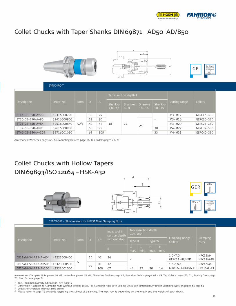
ST16-GB-B50-A=79 52316000790
AD/B
30 79
18 22
--
M3–M12 GERC16-GBDST20-GB-B50-A=80 52416000800 32 80
25
M3–M16 GERC20-GBDST25-GB-B50-A=84 52516000840 40 84 M3–M20 GERC25-GBDST32-GB-B50-A=95 52616000950 50 95 30 M4–M27 GERC32-GBDST40-GB-B50-A=105 52716001050 63 105 33 M4–M33 GERC40-GBD
CP11M-HSK-A32-A=403) 43223000400A
16 40 24- -
1,0–7,0GERC11-HP/HPD
HPC11M•HPC11M-DI
CP16M-HSK-A32-A=503) 4332300050022
50 32 1,0–10,0GERC16-HP/HPD/GBD
HPC16MS•HPC16MS-DICP16M-HSK-A32-A=100 43323001000 100 67 44 27 30 14
Collet Chucks with Taper Shanks DIN 69871 – AD50 | AD/B50
CENTRO|P – Version for HPC Clamping Nuts SYNCHRO|T
Description Order-No. Form D A
Tap insertion depth T
Cutting range ColletsShank-ø2,8 – 7,1
Shank-ø8 – 9
Shank-ø10 – 16
Shank-ø18 – 25
CENTRO|P – Version for HPC Clamping Nuts CENTRO|P – Slim Version for HPCM Mini Clamping Nuts
Description Order-No. Form D A 2)
max. tool in-sertion depth without stop
Tool insertion depth with stop
Clamping Range / Collets
ClampingNutsType U Type W
EG max.
G min.
H max.
H min.
1) MQL (minimal quantity lubrication) see page 52) Dimension A applies to Clamping Nuts without Sealing Discs. For Clamping Nuts with Sealing Discs see dimension A1) under Clamping Nuts on pages 60 and 613) Extra short version, without stop screw4) Please refer to page 76 onwards regarding the subject of balancing. The max. rpm is depending on the length and the weight of each chuck.
Accessories: Clamping Nuts pages 60, 61, Wrenches pages 65, 66, Mounting Devices page 66, Precision Collets pages 67 - 69, Tap Collets pages 70, 71, Sealing Discs page 73, Stop Screws page 74
Accessories: Wrenches pages 65, 66, Mounting Devices page 66, Tap Collets pages 70, 71
Collet Chucks with Hollow Tapers DIN 69893/ISO 12164 – HSK-A32
G B
G ERM I N I
G 6 , 312.000 rpmorU ≤ 1 gmm⁴)
M Q L 1) U≤1gmm max. 50.000
rpm⁴)
D
A
E
T
A
D

22 FAHRION || Tool clamping systems
CP20-HSK-A32-A=503) 44423000500 A 32 50 35 - - - -1,0–13,0GERC20-HP/HPD/GBD
HPC20•HPC20-DI
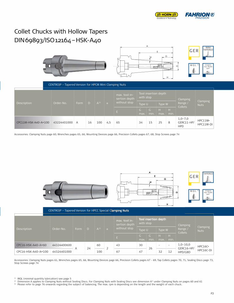
CP11M-HSK-A40-A=60 43224000600A 16
60 40 2416
- - 1,0–7,0GERC11-HP/HPD
HPC11M•HPC11M-DICP11M-HSK-A40-A=130 43224001300 130 75 32 22 7
CENTRO|P – Version for HPC Clamping Nuts
Description Order-No. Form D A 2)
max. tool in-sertion depth without stop
Tool insertion depth with stop
Clamping Range / Collets
ClampingNutsType U Type W
EG max.
G min.
H max.
H min.
CENTRO|P – Slim Version for HPCM Mini Clamping Nuts
Description Order-No. Form D A 2)
max. tool in-sertion depth without stop
Tool insertion depth with stop
Clamping Range / Collets
ClampingNutsType U Type W
EG max.
G min.
H max.
H min.
Collet Chucks with Hollow Tapers DIN 69893/ISO 12164 – HSK-A32
Accessories: Clamping Nuts pages 62, 64, Wrenches pages 65, 66, Mounting Devices page 66, Precision Collets pages 67 - 69, Tap Collets pages 70, 71, Sealing Discs page 73
1) MQL (minimal quantity lubrication) see page 52) Dimension A applies to Clamping Nuts without Sealing Discs. For Clamping Nuts with Sealing Discs see dimension A1) under Clamping Nuts on pages 60, 62 and 643) Extra short version, without stop screw4) Please refer to page 76 onwards regarding the subject of balancing. The max. rpm is depending on the length and the weight of each chuck.
Accessories: Clamping Nuts page 60, Wrenches pages 65, 66, Mounting Devices page 66, Precision Collets pages 67, 68, Stop Screws page 74
Collet Chucks with Hollow Tapers DIN 69893/ISO 12164 – HSK-A40
G ERSTANDARD
G ERM I N I
M Q L 1)
M Q L 1) U≤1gmm max. 30.000
rpm⁴)
U≤1gmm max. 42.000
rpm⁴)
D
E
A
D
A
E
G
23
CPC11M-HSK-A40-A=100 43224401000 A 16 100 4,5 65 34 15 25 81,0–7,0GERC11-HP/HPD
HPC11M•HPC11M-DI
CPC16-HSK-A40-A=60 44324400600A 24
602
43 3026
- - 1,0–10,0GERC16-HP/HPD/GBD
HPC16C•HPC16C-DICPC16-HSK-A40-A=100 44324401000 100 67 47 32 12
CENTRO|P – Version for HPC Clamping Nuts
CENTRO|P – Slim Version for HPCM Mini Clamping Nuts
CENTRO|P – Tapered Version for HPCM Mini Clamping Nuts
Description Order-No. Form D A 2) α
max. tool in-sertion depth without stop
Tool insertion depth with stop
Clamping Range /Collets
ClampingNutsType U Type W
EG max.
G min.
H max.
H min.
CENTRO|P – Tapered Version for HPCC Special Clamping Nuts
Description Order-No. Form D A 2) α
max. tool in-sertion depth without stop
Tool insertion depth with stop
Clamping Range /Collets
ClampingNutsType U Type W
EG max.
G min.
H max.
H min.
Accessories: Clamping Nuts page 60, Wrenches pages 65, 66, Mounting Devices page 66, Precision Collets pages 67, 68, Stop Screws page 74
Collet Chucks with Hollow Tapers DIN 69893/ISO 12164 – HSK-A40
Accessories: Clamping Nuts pages 61, Wrenches pages 65, 66, Mounting Devices page 66, Precision Collets pages 67 - 69, Tap Collets pages 70, 71, Sealing Discs page 73, Stop Screws page 74
1) MQL (minimal quantity lubrication) see page 52) Dimension A applies to Clamping Nuts without Sealing Discs. For Clamping Nuts with Sealing Discs see dimension A1) under Clamping Nuts on pages 60 and 613) Please refer to page 76 onwards regarding the subject of balancing. The max. rpm is depending on the length and the weight of each chuck.
G ERMINI
TAPERED
G ERTAPERED
M Q L 1)
M Q L 1)
U≤1gmm max. 40.000
rpm³)
U≤1gmm max. 42.000
rpm³)
A
E
G
H
D
α
CENTRO|P – Tapered Version for HPCC Special Clamping Nuts
max. tool in- Tool insertion depth
A
E G
H H H
D
α
24 FAHRION || Tool clamping systems
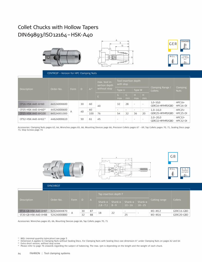
CP16-HSK-A40-A=60 44324000600
A
30 6040
32 28 - -1,0–10,0GERC16-HP/HPD/GBD
HPC16•HPC16-DI
CP25-HSK-A40-A=603) 4452400060040
60 - - - - 1,0–16,0GERC25-HP/HPD/GBD
HPC25•HPC25-DICP25-HSK-A40-A=100 44524001000 100 76 54 32 36 20
CP32-HSK-A40-A=613) 44624000610 50 61 45 - - - -2,0–20,0GERC32-HP/HPD/GBD
HPC32•HPC32-DI
ST16-GB-HSK-A40-A=87 52324000870A
30 8718 22
--
M3–M12 GERC16-GBDST20-GB-HSK-A40-A=88 52424000880 32 88 25 M3–M16 GERC20-GBD
CENTRO|P – Version for HPC Clamping Nuts
Description Order-No. Form D A 2)
max. tool in-sertion depth without stop
Tool insertion depth with stop
Clamping Range / Collets
ClampingNutsType U Type W
EG max.
G min.
H max.
H min.
Collet Chucks with Hollow Tapers DIN 69893/ISO 12164 – HSK-A40
1) MQL (minimal quantity lubrication) see page 52) Dimension A applies to Clamping Nuts without Sealing Discs. For Clamping Nuts with Sealing Discs see dimension A1) under Clamping Nuts on pages 62 and 643) Extra short version, without stop screw4) Please refer to page 76 onwards regarding the subject of balancing. The max. rpm is depending on the length and the weight of each chuck.
SYNCHRO|T
Description Order-No. Form D A
Tap insertion depth T
Cutting range ColletsShank-ø2,8 – 7,1
Shank-ø8 – 9
Shank-ø10 – 16
Shank-ø18 – 25
Accessories: Clamping Nuts pages 62, 64, Wrenches pages 65, 66, Mounting Devices page 66, Precision Collets pages 67 - 69, Tap Collets pages 70, 71, Sealing Discs page 73, Stop Screws page 74
Accessories: Wrenches pages 65, 66, Mounting Devices page 66, Tap Collets pages 70, 71
G ERSTANDARD
G B
M Q L 1)
M Q L 1)
U≤1gmm max. 35.000
rpm⁴)
G 6 , 318.000 rpmorU ≤ 1 gmm⁴)
D
G
E A
Name:±0,06
±0,1
±0,2
±0,3
±0,5
±1,0
44324000600Artikel-Nr.:
Artikel-Bez. 2:Gez.Gepr.Gen.
RohteilNr.
Kanten 0,3x45°gebrochen
Passmaß Abmaß
Maßstab:
1:1
-10
10-30
30-80
80-180
180-500
500-1000
zul.Abweichg.n.tol.bearb.Maße:
Werkstoff:
Datum:16.05.08 Ho
SpannzangenfutterCP16-HSK-A40-A=60
verg. auf:Einsatztiefe:
Wärmebehandlung:
angelassen auf:
Gewicht: g
. .FAHRION
30.0
8.20
11 -
K:\S
W-A
WU
\Mod
elle
\CP-
Futt
er\Z
usam
men
stel
lung
en\C
P16u
.CP1
6M\C
P16\
CP-K
atal
og\4
4324
0006
00-K
T
D
A
25
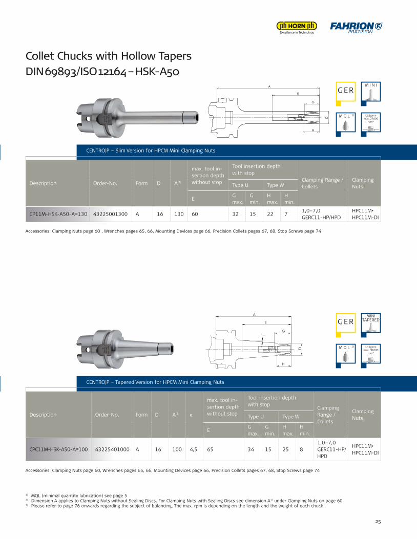
CPC11M-HSK-A50-A=100 43225401000 A 16 100 4,5 65 34 15 25 81,0–7,0GERC11-HP/HPD
HPC11M•HPC11M-DI
CP11M-HSK-A50-A=130 43225001300 A 16 130 60 32 15 22 71,0–7,0GERC11-HP/HPD
HPC11M•HPC11M-DI
CENTRO|P – Version for HPC Clamping Nuts
CENTRO|P – Tapered Version for HPCM Mini Clamping Nuts
Description Order-No. Form D A 2) α
max. tool in-sertion depth without stop
Tool insertion depth with stop
Clamping Range / Collets
ClampingNutsType U Type W
EG max.
G min.
H max.
H min.
Collet Chucks with Hollow Tapers DIN 69893/ISO 12164 – HSK-A50
CENTRO|P – Slim Version for HPCM Mini Clamping Nuts
Description Order-No. Form D A 2)
max. tool in-sertion depth without stop
Tool insertion depth with stop
Clamping Range / Collets
ClampingNutsType U Type W
EG max.
G min.
H max.
H min.
SYNCHRO|T
Accessories: Wrenches pages 65, 66, Mounting Devices page 66, Tap Collets pages 70, 71
Accessories: Clamping Nuts page 60 , Wrenches pages 65, 66, Mounting Devices page 66, Precision Collets pages 67, 68, Stop Screws page 74
Accessories: Clamping Nuts page 60, Wrenches pages 65, 66, Mounting Devices page 66, Precision Collets pages 67, 68, Stop Screws page 74
1) MQL (minimal quantity lubrication) see page 52) Dimension A applies to Clamping Nuts without Sealing Discs. For Clamping Nuts with Sealing Discs see dimension A1) under Clamping Nuts on page 603) Please refer to page 76 onwards regarding the subject of balancing. The max. rpm is depending on the length and the weight of each chuck.
G ERM I N I
MINITAPEREDG ER
M Q L 1)
M Q L 1) U≤1gmm max. 27.000
rpm³)
U≤1gmm max. 30.000
rpm³)
G
H
E
A
D
E
H
G
A
D
�
26 FAHRION || Tool clamping systems
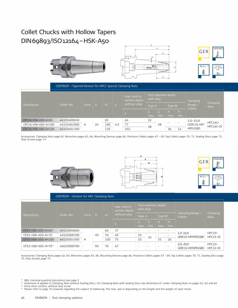
CP25-HSK-A50-A=60 3 44525000600
A40
60 37 - - - -1,0–16,0GERC25-HP/HPD/GBD
HPC25•HPC25-DICP25-HSK-A50-A=70 44525000700 70 49 35
34- -
CP25-HSK-A50-A=100 44525001000 100 75 53 35 20
CP32-HSK-A50-A=70 3 44625000700 50 70 47 - - - -2,0–20,0GERC32-HP/HPD/GBD
HPC32•HPC32-DI
CPC16-HSK-A50-A=65 44325400650A 24
654,5
44 3228
- - 1,0–10,0GERC16-HP/HPD/GBD
HPC16C•HPC16C-DICPC16-HSK-A50-A=100 44325401000 100 77
38CPC16-HSK-A50-A=130 44325401300 130 102 36 14
CENTRO|P – Version for HPC Clamping Nuts
Description Order-No. Form D A 2)
max. tool in-sertion depth without stop
Tool insertion depth with stop
Clamping Range /Collets
ClampingNutsType U Type W
EG max.
G min.
H max.
H min.
CENTRO|P – Tapered Version for HPCC Special Clamping Nuts
Description Order-No. Form D A 2) α
max. tool in-sertion depth without stop
Tool insertion depth with stop
Clamping Range /Collets
ClampingNutsType U Type W
EG max.
G min.
H max.
H min.
Collet Chucks with Hollow Tapers DIN 69893/ISO 12164 – HSK-A50
1) MQL (minimal quantity lubrication) see page 52) Dimension A applies to Clamping Nuts without Sealing Discs. For Clamping Nuts with Sealing Discs see dimension A1) under Clamping Nuts on pages 61, 62 and 643) Extra short version, without stop screw4) Please refer to page 76 onwards regarding the subject of balancing. The max. rpm is depending on the length and the weight of each chuck.
Accessories: Clamping Nuts page 62, Wrenches pages 65, 66, Mounting Devices page 66, Precision Collets pages 67 - 69, Tap Collets pages 70, 71, Sealing Discs page 73, Stop Screws page 74
Accessories: Clamping Nuts pages 62, 64, Wrenches pages 65, 66, Mounting Devices page 66, Precision Collets pages 67 - 69, Tap Collets pages 70, 71, Sealing Discs page 73, Stop Screws page 74
G ERTAPERED
G ERSTANDARD
M Q L 1)
M Q L 1)
U≤1gmm max. 30.000
rpm⁴)
U≤1gmm max. 25.000
rpm⁴)
H
G
D
E
A
α
G
A
D
D
E

27
ST16-GB-HSK-A50-A=87 52325000870
A
30 87
18 22
--
M3–M12 GERC16-GBDST20-GB-HSK-A50-A=88 52425000880 32 88
25M3–M16 GERC20-GBD
ST25-GB-HSK-A50-A=92 52525000920 40 92 M3–M20 GERC25-GBDST32-GB-HSK-A50-A=116 52625001160 50 116 30 M4–M27 GERC32-GBD
CENTRO|P – Version for HPC Clamping Nuts
CENTRO|P – Tapered Version for HPCC Special Clamping Nuts
Collet Chucks with Hollow Tapers DIN 69893/ISO 12164 – HSK-A50
SYNCHRO|T
Description Order-No. Form D A
Tap insertion depth T
Cutting range ColletsShank-ø2,8 – 7,1
Shank-ø8 – 9
Shank-ø10 – 16
Shank-ø18 – 25
Accessories: Wrenches pages 65, 66, Mounting Devices page 66, Tap Collets pages 70, 71
1) MQL (minimal quantity lubrication) see page 52) Please refer to page 76 onwards regarding the subject of balancing. The max. rpm is depending on the length and the weight of each chuck.
G B
M Q L 1) G 6 , 318.000 rpmorU ≤ 1 gmm²)
T
D
A
28 FAHRION || Tool clamping systems
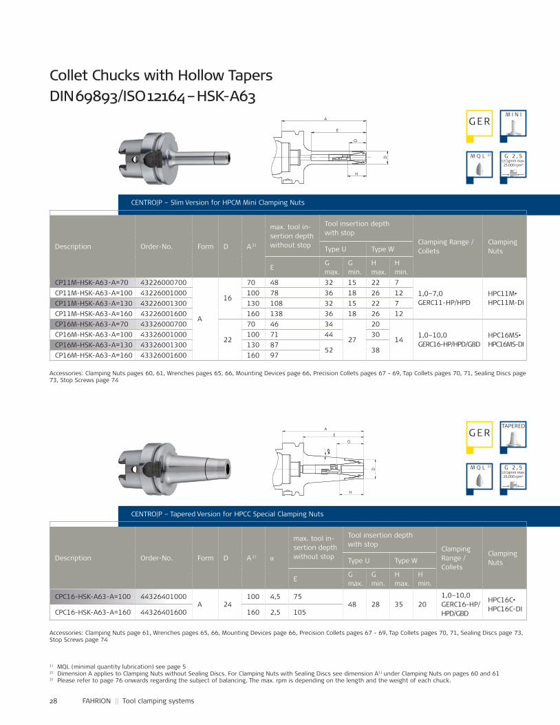
CP11M-HSK-A63-A=70 43226000700
A
16
70 48 32 15 22 71,0–7,0GERC11-HP/HPD
HPC11M•HPC11M-DI
CP11M-HSK-A63-A=100 43226001000 100 78 36 18 26 12CP11M-HSK-A63-A=130 43226001300 130 108 32 15 22 7CP11M-HSK-A63-A=160 43226001600 160 138 36 18 26 12CP16M-HSK-A63-A=70 43326000700
22
70 46 34
27
20
141,0–10,0GERC16-HP/HPD/GBD
HPC16MS•HPC16MS-DI
CP16M-HSK-A63-A=100 43326001000 100 71 44 30CP16M-HSK-A63-A=130 43326001300 130 87
52 38CP16M-HSK-A63-A=160 43326001600 160 97
CPC16-HSK-A63-A=100 44326401000A 24
100 4,5 7548 28 35 20
1,0–10,0GERC16-HP/HPD/GBD
HPC16C•HPC16C-DICPC16-HSK-A63-A=160 44326401600 160 2,5 105
CENTRO|P – Slim Version for HPCM Mini Clamping Nuts
Description Order-No. Form D A 2)
max. tool in-sertion depth without stop
Tool insertion depth with stop
Clamping Range / Collets
ClampingNutsType U Type W
EG max.
G min.
H max.
H min.
CENTRO|P – Tapered Version for HPCC Special Clamping Nuts
Description Order-No. Form D A 2) α
max. tool in-sertion depth without stop
Tool insertion depth with stop
Clamping Range / Collets
ClampingNutsType U Type W
EG max.
G min.
H max.
H min.
Collet Chucks with Hollow Tapers DIN 69893/ISO 12164 – HSK-A63
1) MQL (minimal quantity lubrication) see page 52) Dimension A applies to Clamping Nuts without Sealing Discs. For Clamping Nuts with Sealing Discs see dimension A1) under Clamping Nuts on pages 60 and 613) Please refer to page 76 onwards regarding the subject of balancing. The max. rpm is depending on the length and the weight of each chuck.
Accessories: Clamping Nuts pages 60, 61, Wrenches pages 65, 66, Mounting Devices page 66, Precision Collets pages 67 - 69, Tap Collets pages 70, 71, Sealing Discs page 73, Stop Screws page 74
Accessories: Clamping Nuts page 61, Wrenches pages 65, 66, Mounting Devices page 66, Precision Collets pages 67 - 69, Tap Collets pages 70, 71, Sealing Discs page 73, Stop Screws page 74
M I N IG ER
G ERTAPERED
M Q L 1)
M Q L 1)
G 2 , 5U≤1gmm max. 25.000 rpm³)
G 2 , 5U≤1gmm max. 25.000 rpm³)
G
EA
D
H
∝
Name:±0,06
±0,1
±0,2
±0,3
±0,5
±1,0
44326401000Artikel-Nr.:
Artikel-Bez. 2:Gez.Gepr.Gen.
RohteilNr.
Kanten 0,3x45°gebrochen
Passmaß Abmaß
Maßstab:
1:1
-10
10-30
30-80
80-180
180-500
500-1000
zul.Abweichg.n.tol.bearb.Maße:
Werkstoff:
Datum:31.08.11 Ca
SpannzangenfutterCPC16-HSK-A63-A=100
verg. auf:Einsatztiefe:
Wärmebehandlung:
angelassen auf:
Gewicht: g
03.0
3.20
14 -
C:\F
AHR
ION
-PD
M\M
odel
le\C
PC-F
utte
r\Zus
amm
enst
ellu
ngen
\CPC
16\C
P-Ka
talo
g\44
3264
0100
0-K
A
D
E
G
H
29
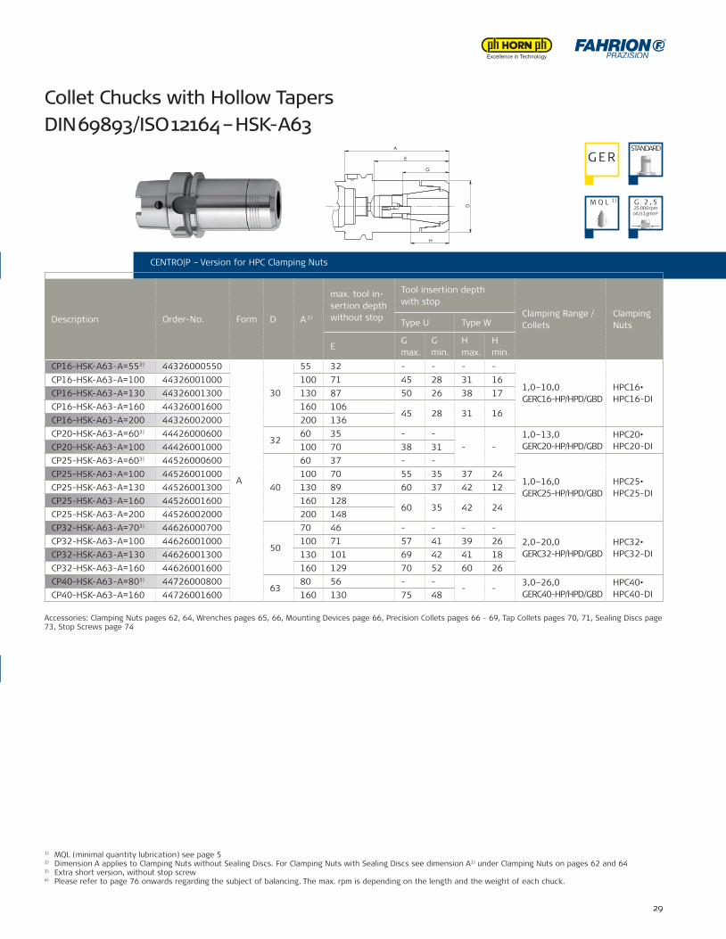
CP16-HSK-A63-A=553) 44326000550
A
30
55 32 - - - -
1,0–10,0GERC16-HP/HPD/GBD
HPC16•HPC16-DI
CP16-HSK-A63-A=100 44326001000 100 71 45 28 31 16CP16-HSK-A63-A=130 44326001300 130 87 50 26 38 17CP16-HSK-A63-A=160 44326001600 160 106
45 28 31 16CP16-HSK-A63-A=200 44326002000 200 136CP20-HSK-A63-A=603) 44426000600
3260 35 - -
- -1,0–13,0GERC20-HP/HPD/GBD
HPC20•HPC20-DICP20-HSK-A63-A=100 44426001000 100 70 38 31
CP25-HSK-A63-A=603) 44526000600
40
60 37 - -
1,0–16,0GERC25-HP/HPD/GBD
HPC25•HPC25-DI
CP25-HSK-A63-A=100 44526001000 100 70 55 35 37 24CP25-HSK-A63-A=130 44526001300 130 89 60 37 42 12CP25-HSK-A63-A=160 44526001600 160 128
60 35 42 24CP25-HSK-A63-A=200 44526002000 200 148CP32-HSK-A63-A=703) 44626000700
50
70 46 - - - -2,0–20,0GERC32-HP/HPD/GBD
HPC32•HPC32-DI
CP32-HSK-A63-A=100 44626001000 100 71 57 41 39 26CP32-HSK-A63-A=130 44626001300 130 101 69 42 41 18CP32-HSK-A63-A=160 44626001600 160 129 70 52 60 26CP40-HSK-A63-A=803) 44726000800
6380 56 - -
- -3,0–26,0GERC40-HP/HPD/GBD
HPC40•HPC40-DICP40-HSK-A63-A=160 44726001600 160 130 75 48
CENTRO|P – Slim Version for HPCM Mini Clamping Nuts
CENTRO|P – Tapered Version for HPCC Special Clamping Nuts
Collet Chucks with Hollow Tapers DIN 69893/ISO 12164 – HSK-A63
1) MQL (minimal quantity lubrication) see page 52) Dimension A applies to Clamping Nuts without Sealing Discs. For Clamping Nuts with Sealing Discs see dimension A1) under Clamping Nuts on pages 62 and 643) Extra short version, without stop screw4) Please refer to page 76 onwards regarding the subject of balancing. The max. rpm is depending on the length and the weight of each chuck.
CENTRO|P – Version for HPC Clamping Nuts
Description Order-No. Form D A 2)
max. tool in-sertion depth without stop
Tool insertion depth with stop
Clamping Range / Collets
ClampingNutsType U Type W
EG max.
G min.
H max.
H min.
Accessories: Clamping Nuts pages 62, 64, Wrenches pages 65, 66, Mounting Devices page 66, Precision Collets pages 66 - 69, Tap Collets pages 70, 71, Sealing Discs page 73, Stop Screws page 74
G ERSTANDARD
M Q L 1) G 2 , 525.000 rpmorU ≤ 1 gmm⁴)
A
E
H
D
G
Name:±0,06
±0,1
±0,2
±0,3
±0,5
±1,0
44626001000Artikel-Nr.:
Artikel-Bez. 2:Gez.Gepr.Gen.
RohteilNr.
Kanten 0,3x45°gebrochen
Passmaß Abmaß
Maßstab:
1:1
-10
10-30
30-80
80-180
180-500
500-1000
zul.Abweichg.n.tol.bearb.Maße:
Werkstoff:
Datum:06.09.11 Ca
SpannzangenfutterCP32-HSK-A63-A=100
verg. auf:Einsatztiefe:
Wärmebehandlung:
angelassen auf:
Gewicht: 1234 g
06.0
9.20
11 -
K:\S
W-A
WU
\Mod
elle
\CP-
Futt
er\Z
usam
men
stel
lung
en\C
P32\
CP-K
atal
og\4
4626
0010
00-K
30 FAHRION || Tool clamping systems
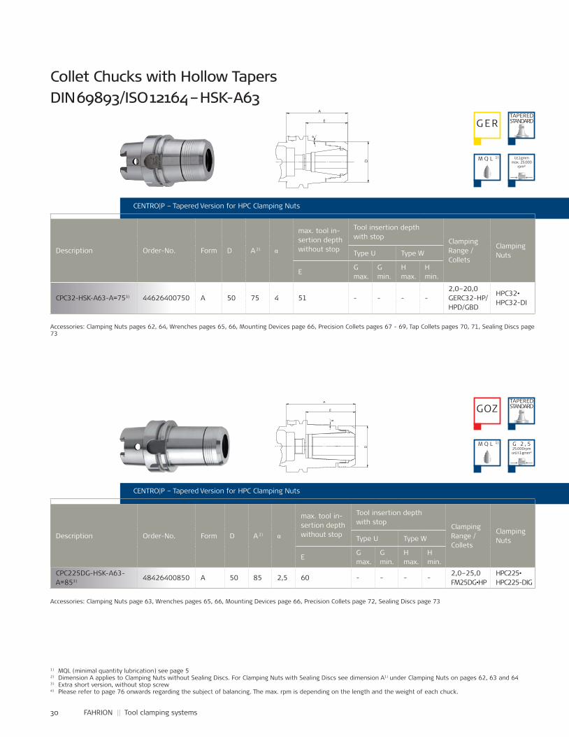
CPC32-HSK-A63-A=753) 44626400750 A 50 75 4 51 - - - -2,0–20,0GERC32-HP/HPD/GBD
HPC32•HPC32-DI
CPC225DG-HSK-A63-A=853) 48426400850 A 50 85 2,5 60 - - - -
2,0–25,0FM25DG•HP
HPC225•HPC225-DIG
CENTRO|P – Tapered Version for HPC Clamping Nuts
Description Order-No. Form D A 2) α
max. tool in-sertion depth without stop
Tool insertion depth with stop
Clamping Range / Collets
ClampingNutsType U Type W
EG max.
G min.
H max.
H min.
Collet Chucks with Hollow Tapers DIN 69893/ISO 12164 – HSK-A63
1) MQL (minimal quantity lubrication) see page 52) Dimension A applies to Clamping Nuts without Sealing Discs. For Clamping Nuts with Sealing Discs see dimension A1) under Clamping Nuts on pages 62, 63 and 643) Extra short version, without stop screw4) Please refer to page 76 onwards regarding the subject of balancing. The max. rpm is depending on the length and the weight of each chuck.
Accessories: Clamping Nuts pages 62, 64, Wrenches pages 65, 66, Mounting Devices page 66, Precision Collets pages 67 - 69, Tap Collets pages 70, 71, Sealing Discs page 73
Accessories: Clamping Nuts page 63, Wrenches pages 65, 66, Mounting Devices page 66, Precision Collets page 72, Sealing Discs page 73
CENTRO|P – Tapered Version for HPC Clamping Nuts
Description Order-No. Form D A 2) α
max. tool in-sertion depth without stop
Tool insertion depth with stop
Clamping Range / Collets
ClampingNutsType U Type W
EG max.
G min.
H max.
H min.
G ERTAPEREDSTANDARD
GOZTAPEREDSTANDARD
M Q L 1)
M Q L 1)
U≤1gmm max. 25.000
rpm⁴)
G 2 , 525.000 rpmorU ≤ 1 gmm⁴)
D
E
A
α
D
E
A
α
31
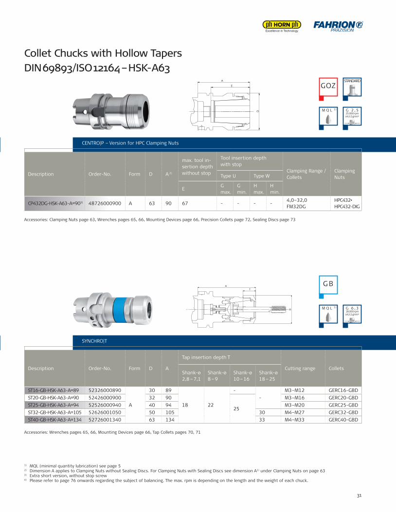
ST16-GB-HSK-A63-A=89 52326000890
A
30 89
18 22
--
M3–M12 GERC16-GBDST20-GB-HSK-A63-A=90 52426000900 32 90
25
M3–M16 GERC20-GBDST25-GB-HSK-A63-A=94 52526000940 40 94 M3–M20 GERC25-GBDST32-GB-HSK-A63-A=105 52626001050 50 105 30 M4–M27 GERC32-GBDST40-GB-HSK-A63-A=134 52726001340 63 134 33 M4–M33 GERC40-GBD
CP432DG-HSK-A63-A=903) 48726000900 A 63 90 67 - - - -4,0–32,0FM32DG
HPC432•HPC432-DIG
CENTRO|P – Tapered Version for HPC Clamping Nuts
Collet Chucks with Hollow Tapers DIN 69893/ISO 12164 – HSK-A63
CENTRO|P – Version for HPC Clamping Nuts
Description Order-No. Form D A 2)
max. tool in-sertion depth without stop
Tool insertion depth with stop
Clamping Range / Collets
ClampingNutsType U Type W
EG max.
G min.
H max.
H min.
SYNCHRO|T
Description Order-No. Form D A
Tap insertion depth T
Cutting range ColletsShank-ø2,8 – 7,1
Shank-ø8 – 9
Shank-ø10 – 16
Shank-ø18 – 25
Accessories: Clamping Nuts page 63, Wrenches pages 65, 66, Mounting Devices page 66, Precision Collets page 72, Sealing Discs page 73
Accessories: Wrenches pages 65, 66, Mounting Devices page 66, Tap Collets pages 70, 71
CENTRO|P – Tapered Version for HPC Clamping Nuts
1) MQL (minimal quantity lubrication) see page 52) Dimension A applies to Clamping Nuts without Sealing Discs. For Clamping Nuts with Sealing Discs see dimension A1) under Clamping Nuts on page 633) Extra short version, without stop screw4) Please refer to page 76 onwards regarding the subject of balancing. The max. rpm is depending on the length and the weight of each chuck.
GOZSTANDARD
G B
M Q L 1)
M Q L 1)
G 2 , 525.000 rpmorU ≤ 1 gmm⁴)
G 6 , 318.000 rpmorU ≤ 1 gmm⁴)
D
A
E
TD
A
32 FAHRION || Tool clamping systems
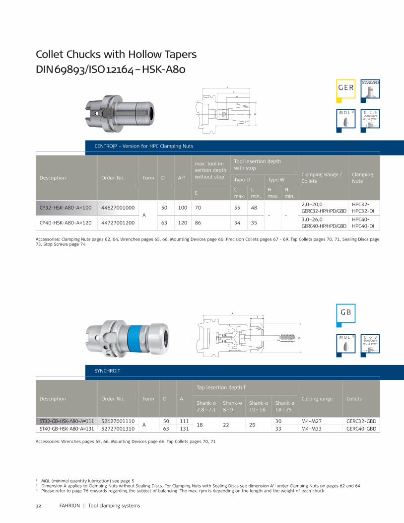
CP32-HSK-A80-A=100 44627001000A
50 100 70 55 48- -
2,0–20,0GERC32-HP/HPD/GBD
HPC32•HPC32-DI
CP40-HSK-A80-A=120 44727001200 63 120 86 54 353,0–26,0GERC40-HP/HPD/GBD
HPC40•HPC40-DI
ST32-GB-HSK-A80-A=111 52627001110A
50 11118 22 25
30 M4–M27 GERC32-GBDST40-GB-HSK-A80-A=131 52727001310 63 131 33 M4–M33 GERC40-GBD
CENTRO|P – Version for HPC Clamping Nuts
Description Order-No. Form D A 2)
max. tool in-sertion depth without stop
Tool insertion depth with stop
Clamping Range / Collets
ClampingNutsType U Type W
EG max.
G min.
H max.
H min.
Collet Chucks with Hollow Tapers DIN 69893/ISO 12164 – HSK-A80
SYNCHRO|T
Description Order-No. Form D A
Tap insertion depth T
Cutting range ColletsShank-ø2,8 – 7,1
Shank-ø8 – 9
Shank-ø10 – 16
Shank-ø18 – 25
1) MQL (minimal quantity lubrication) see page 52) Dimension A applies to Clamping Nuts without Sealing Discs. For Clamping Nuts with Sealing Discs see dimension A1) under Clamping Nuts on pages 62 and 643) Please refer to page 76 onwards regarding the subject of balancing. The max. rpm is depending on the length and the weight of each chuck.
Accessories: Clamping Nuts pages 62, 64, Wrenches pages 65, 66, Mounting Devices page 66, Precision Collets pages 67 - 69, Tap Collets pages 70, 71, Sealing Discs page 73, Stop Screws page 74
Accessories: Wrenches pages 65, 66, Mounting Devices page 66, Tap Collets pages 70, 71
G ERSTANDARD
G B
M Q L 1)
M Q L 1)
G 2 , 525.000 rpmorU ≤ 1 gmm³)
G 6 , 318.000 rpmorU ≤ 1 gmm³)
T
D
A
D
G
E
A
Name:±0,06
±0,1
±0,2
±0,3
±0,5
±1,0
44627001000Artikel-Nr.:
Artikel-Bez. 2:Gez.Gepr.Gen.
RohteilNr.
Kanten 0,3x45°gebrochen
Passmaß Abmaß
Maßstab:
1:11:2
-10
10-30
30-80
80-180
180-500
500-1000
zul.Abweichg.n.tol.bearb.Maße:
Werkstoff:
Datum:31.08.11 Ca
SapnnzangenfutterCP32-HSK-A80-A=100
verg. auf:Einsatztiefe:
Wärmebehandlung:
angelassen auf:
Gewicht:
. .FAHRION
06.0
9.20
11 -
K:\S
W-A
WU
\Mod
elle
\CP-
Futt
er\Z
usam
men
stel
lung
en\C
P32\
CP-K
atal
og\4
4627
0010
00-K
33
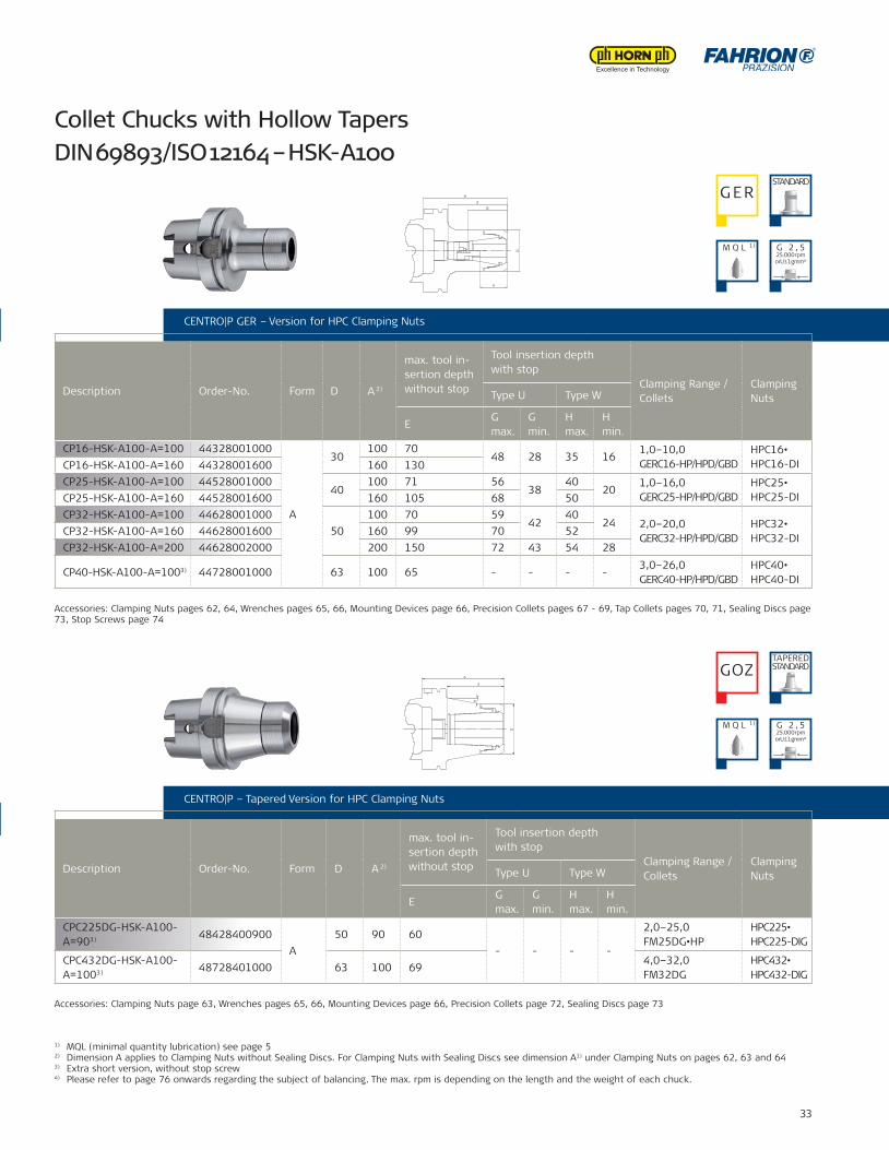
CP16-HSK-A100-A=100 44328001000
A
30100 70
48 28 35 161,0–10,0GERC16-HP/HPD/GBD
HPC16•HPC16-DICP16-HSK-A100-A=160 44328001600 160 130
CP25-HSK-A100-A=100 4452800100040
100 71 5638
4020
1,0–16,0GERC25-HP/HPD/GBD
HPC25•HPC25-DICP25-HSK-A100-A=160 44528001600 160 105 68 50
CP32-HSK-A100-A=100 4462800100050
100 70 5942
4024 2,0–20,0
GERC32-HP/HPD/GBDHPC32•HPC32-DI
CP32-HSK-A100-A=160 44628001600 160 99 70 52CP32-HSK-A100-A=200 44628002000 200 150 72 43 54 28
CP40-HSK-A100-A=1003) 44728001000 63 100 65 - - - -3,0–26,0GERC40-HP/HPD/GBD
HPC40•HPC40-DI
CPC225DG-HSK-A100-A=903) 48428400900
A50 90 60
- - - -
2,0–25,0FM25DG•HP
HPC225•HPC225-DIG
CPC432DG-HSK-A100-A=1003) 48728401000 63 100 69
4,0–32,0FM32DG
HPC432•HPC432-DIG
CENTRO|P – Version for HPC Clamping Nuts
1) MQL (minimal quantity lubrication) see page 52) Dimension A applies to Clamping Nuts without Sealing Discs. For Clamping Nuts with Sealing Discs see dimension A1) under Clamping Nuts on pages 62, 63 and 643) Extra short version, without stop screw4) Please refer to page 76 onwards regarding the subject of balancing. The max. rpm is depending on the length and the weight of each chuck.
Collet Chucks with Hollow Tapers DIN 69893/ISO 12164 – HSK-A100
CENTRO|P GER – Version for HPC Clamping Nuts
Description Order-No. Form D A 2)
max. tool in-sertion depth without stop
Tool insertion depth with stop
Clamping Range / Collets
ClampingNutsType U Type W
EG max.
G min.
H max.
H min.
SYNCHRO|TCENTRO|P – Tapered Version for HPC Clamping Nuts
Description Order-No. Form D A 2)
max. tool in-sertion depth without stop
Tool insertion depth with stop
Clamping Range / Collets
ClampingNutsType U Type W
EG max.
G min.
H max.
H min.
Accessories: Clamping Nuts pages 62, 64, Wrenches pages 65, 66, Mounting Devices page 66, Precision Collets pages 67 - 69, Tap Collets pages 70, 71, Sealing Discs page 73, Stop Screws page 74
Accessories: Clamping Nuts page 63, Wrenches pages 65, 66, Mounting Devices page 66, Precision Collets page 72, Sealing Discs page 73
G ERSTANDARD
GOZTAPEREDSTANDARD
M Q L 1)
M Q L 1)
G 2 , 525.000 rpmorU ≤ 1 gmm⁴)
G 2 , 525.000 rpmorU ≤ 1 gmm⁴)
D
G
E
A
H
Name:±0,06
±0,1
±0,2
±0,3
±0,5
±1,0
44628001000Artikel-Nr.:
Artikel-Bez. 2:
Benennung:
Gez.Gepr.Gen.
RohteilNr.
Kanten 0,3x45°gebrochen
Passmaß Abmaß
Maßstab:
1:11:2
-10
10-30
30-80
80-180
180-500
500-1000
zul.Abweichg.n.tol.bearb.Maße:
Werkstoff:
Datum:31.08.11 Ca
SpannzangenfutterCP32-HSK-A100-A=100
verg. auf:Einsatztiefe:
Wärmebehandlung:
angelassen auf:
Gewicht: 2.58 g
. .FAHRION
06.0
9.20
11 -
K:\S
W-A
WU
\Mod
elle
\CP-
Futt
er\Z
usam
men
stel
lung
en\C
P32\
CP-K
atal
og\4
4628
0010
00-K
D
E
A
α
Name:±0,06
±0,1
±0,2
±0,3
±0,5
±1,0
48728401000Artikel-Nr.:
Artikel-Bez. 2:Gez.Gepr.Gen.
RohteilNr.
Kanten 0,3x45°gebrochen
Passmaß Abmaß
Maßstab:
1:1
-10
10-30
30-80
80-180
180-500
500-1000
zul.Abweichg.n.tol.bearb.Maße:
Werkstoff:
Datum:31.08.11 Ca
SpannzangenfutterCPC432DG-HSK-A100-A=100
verg. auf:Einsatztiefe:
Wärmebehandlung:
angelassen auf:
Gewicht: g
. .FAHRIONPRAZISION12
.09.
2011
- K:
\SW
-AW
U\M
odel
le\C
PC-F
utte
r\Zu
sam
men
stel
lung
en\C
PC43
2DG
\Kat
alog
\487
2840
1000
-K
34 FAHRION || Tool clamping systems
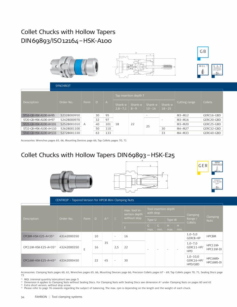
ST16-GB-HSK-A100-A=95 52328000950
A
30 95
18 22
--
M3–M12 GERC16-GBDST20-GB-HSK-A100-A=97 52428000970 32 97
25
M3–M16 GERC20-GBDST25-GB-HSK-A100-A=101 52528001010 40 101 M3–M20 GERC25-GBDST32-GB-HSK-A100-A=110 52628001100 50 110 30 M4–M27 GERC32-GBDST40-GB-HSK-A100-A=133 52728001330 63 133 33 M4–M33 GERC40-GBD
CPC8M-HSK-E25-A=353) 43142000350
E
10
35
- 16
- - - -
1,0–5,0GERC8-HP
HPC8M
CPC11M-HSK-E25-A=353) 43242000350 16 2,5 221,0–7,0GERC11-HP/HPD
HPC11M•HPC11M-DI
CPC16M-HSK-E25-A=453) 43342000450 22 45 - 301,0–10,0GERC16-HP/HPD/GBD
HPC16MS•HPC16MS-DI
SYNCHRO|T
Description Order-No. Form D A
Tap insertion depth T
Cutting range ColletsShank-ø2,8 – 7,1
Shank-ø8 – 9
Shank-ø10 – 16
Shank-ø18 – 25
CENTRO|P – Tapered Version for HPCM Mini Clamping Nuts
Description Order-No. Form D A 2) �
max. tool in-sertion depth without stop
Tool insertion depth with stop
Clamping Range / Collets
ClampingNutsType U Type W
EG max.
G min.
H max.
H min.
1) MQL (minimal quantity lubrication) see page 52) Dimension A applies to Clamping Nuts without Sealing Discs. For Clamping Nuts with Sealing Discs see dimension A1) under Clamping Nuts on pages 60 and 613) Extra short version, without stop screw4) Please refer to page 76 onwards regarding the subject of balancing. The max. rpm is depending on the length and the weight of each chuck.
Collet Chucks with Hollow Tapers DIN 69893/ISO 12164 – HSK-A100
Collet Chucks with Hollow Tapers DIN 69893 – HSK-E25
Accessories: Wrenches pages 65, 66, Mounting Devices page 66, Tap Collets pages 70, 71
Accessories: Clamping Nuts pages 60, 61, Wrenches pages 65, 66, Mounting Devices page 66, Precision Collets pages 67 - 69, Tap Collets pages 70, 71, Sealing Discs page 73
G B
G ERMINI
TAPERED
M Q L 1) G 6 , 318.000 rpmorU ≤ 1 gmm⁴)
U≤1gmm max. 60.000
rpm⁴)
D E
A
α
T
D
A
35
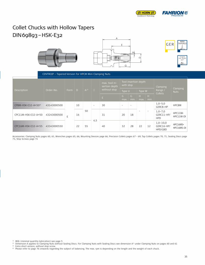
CP8M-HSK-E32-A=503) 43143000500
E
10
50
- 30 - -
- -
1,0–5,0GERC8-HP
HPC8M
CPC11M-HSK-E32-A=50 43243000500 16
4,5
31 20 181,0–7,0GERC11-HP/HPD
HPC11M•HPC11M-DI
CPC16M-HSK-E32-A=55 43343000550 22 55 40 32 28 22 121,0–10,0GERC16-HP/HPD/GBD
HPC16MS•HPC16MS-DI
CENTRO|P – Tapered Version for HPCM Mini Clamping Nuts
Description Order-No. Form D A 2) �
max. tool in-sertion depth without stop
Tool insertion depth with stop
Clamping Range / Collets
ClampingNutsType U Type W
EG max.
G min.
H max.
H min.
SYNCHRO|T
CENTRO|P – Tapered Version for HPCM Mini Clamping Nuts
1) MQL (minimal quantity lubrication) see page 52) Dimension A applies to Clamping Nuts without Sealing Discs. For Clamping Nuts with Sealing Discs see dimension A1) under Clamping Nuts on pages 60 and 613) Extra short version, without stop screw4) Please refer to page 76 onwards regarding the subject of balancing. The max. rpm is depending on the length and the weight of each chuck.
Collet Chucks with Hollow Tapers DIN 69893 – HSK-E32
Accessories: Wrenches pages 65, 66, Mounting Devices page 66, Tap Collets pages 70, 71
Accessories: Clamping Nuts pages 60, 61, Wrenches pages 65, 66, Mounting Devices page 66, Precision Collets pages 67 - 69, Tap Collets pages 70, 71, Sealing Discs page 73, Stop Screws page 74
G ERMINI
TAPERED
U≤1gmm max. 50.000
rpm⁴)
D
α
G
A
E
36 FAHRION || Tool clamping systems
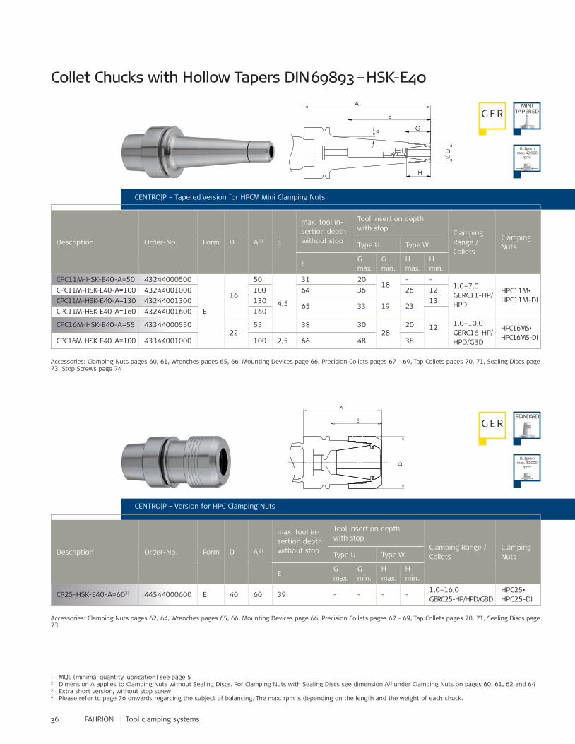
CP25-HSK-E40-A=603) 44544000600 E 40 60 39 - - - -1,0–16,0GERC25-HP/HPD/GBD
HPC25•HPC25-DI
CPC11M-HSK-E40-A=50 43244000500
E
16
50
4,5
31 2018
- -1,0–7,0GERC11-HP/HPD
HPC11M•HPC11M-DI
CPC11M-HSK-E40-A=100 43244001000 100 64 36 26 12CPC11M-HSK-E40-A=130 43244001300 130
65 33 19 2313
CPC11M-HSK-E40-A=160 43244001600 160
12CPC16M-HSK-E40-A=55 4334400055022
55 38 3028
20 1,0–10,0GERC16-HP/HPD/GBD
HPC16MS•HPC16MS-DICPC16M-HSK-E40-A=100 43344001000 100 2,5 66 48 38
1) MQL (minimal quantity lubrication) see page 52) Dimension A applies to Clamping Nuts without Sealing Discs. For Clamping Nuts with Sealing Discs see dimension A1) under Clamping Nuts on pages 60, 61, 62 and 643) Extra short version, without stop screw4) Please refer to page 76 onwards regarding the subject of balancing. The max. rpm is depending on the length and the weight of each chuck.
CENTRO|P – Version for HPC Clamping Nuts
Description Order-No. Form D A 2)
max. tool in-sertion depth without stop
Tool insertion depth with stop
Clamping Range / Collets
ClampingNutsType U Type W
EG max.
G min.
H max.
H min.
Accessories: Clamping Nuts pages 62, 64, Wrenches pages 65, 66, Mounting Devices page 66, Precision Collets pages 67 - 69, Tap Collets pages 70, 71, Sealing Discs page 73
G ERSTANDARD
CENTRO|P – Tapered Version for HPCM Mini Clamping Nuts
Description Order-No. Form D A 2) α
max. tool in-sertion depth without stop
Tool insertion depth with stop
Clamping Range / Collets
ClampingNutsType U Type W
EG max.
G min.
H max.
H min.
Collet Chucks with Hollow Tapers DIN 69893 – HSK-E40
Accessories: Clamping Nuts pages 60, 61, Wrenches pages 65, 66, Mounting Devices page 66, Precision Collets pages 67 - 69, Tap Collets pages 70, 71, Sealing Discs page 73, Stop Screws page 74
G ERMINI
TAPERED
U≤1gmm max. 42.000
rpm⁴)
U≤1gmm max. 30.000
rpm⁴)
E
A
D
Name:±0,06
±0,1
±0,2
±0,3
±0,5
±1,0
44544000600Artikel-Nr.:
Artikel-Bez. 2:Gez.Gepr.Gen.
RohteilNr.
Kanten 0,3x45°gebrochen
Passmaß Abmaß
Maßstab:
1:1
-10
10-30
30-80
80-180
180-500
500-1000
zul.Abweichg.n.tol.bearb.Maße:
Werkstoff:
Datum:30.08.11 Ho
CP25-HSK-E40-A=60
verg. auf:Einsatztiefe:
Wärmebehandlung:
angelassen auf:
Gewicht: 1234 g
12.0
9.20
11 -
K:\S
W-A
WU
\Mod
elle
\CP-
Futt
er\Z
usam
men
stel
lung
en\C
P25\
CP-K
atal
og\4
4544
0006
00-K
A
D
G
H
E
α
37
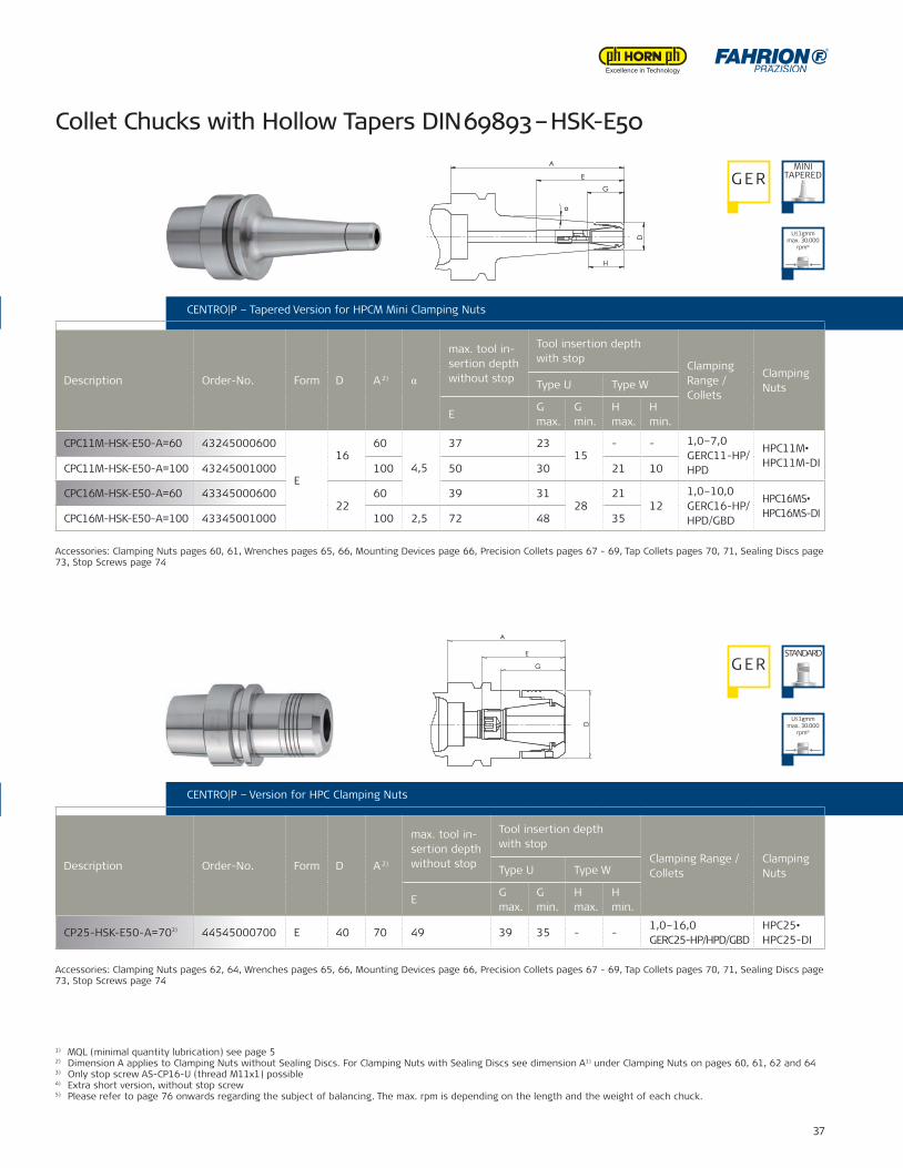
CP25-HSK-E50-A=703) 44545000700 E 40 70 49 39 35 - -1,0–16,0GERC25-HP/HPD/GBD
HPC25•HPC25-DI
CPC11M-HSK-E50-A=60 43245000600
E
1660
4,5
37 2315
- - 1,0–7,0GERC11-HP/HPD
HPC11M•HPC11M-DICPC11M-HSK-E50-A=100 43245001000 100 50 30 21 10
CPC16M-HSK-E50-A=60 4334500060022
60 39 3128
2112
1,0–10,0GERC16-HP/HPD/GBD
HPC16MS•HPC16MS-DICPC16M-HSK-E50-A=100 43345001000 100 2,5 72 48 35
CENTRO|P – Version for HPC Clamping Nuts
Description Order-No. Form D A 2)
max. tool in-sertion depth without stop
Tool insertion depth with stop
Clamping Range / Collets
ClampingNutsType U Type W
EG max.
G min.
H max.
H min.
CENTRO|P – Tapered Version for HPCM Mini Clamping Nuts
Description Order-No. Form D A 2) α
max. tool in-sertion depth without stop
Tool insertion depth with stop
Clamping Range / Collets
ClampingNutsType U Type W
EG max.
G min.
H max.
H min.
1) MQL (minimal quantity lubrication) see page 52) Dimension A applies to Clamping Nuts without Sealing Discs. For Clamping Nuts with Sealing Discs see dimension A1) under Clamping Nuts on pages 60, 61, 62 and 643) Only stop screw AS-CP16-U (thread M11x1) possible4) Extra short version, without stop screw5) Please refer to page 76 onwards regarding the subject of balancing. The max. rpm is depending on the length and the weight of each chuck.
CENTRO|P – Version for HPC Clamping Nuts
Accessories: Clamping Nuts pages 60, 61, Wrenches pages 65, 66, Mounting Devices page 66, Precision Collets pages 67 - 69, Tap Collets pages 70, 71, Sealing Discs page 73, Stop Screws page 74
Accessories: Clamping Nuts pages 62, 64, Wrenches pages 65, 66, Mounting Devices page 66, Precision Collets pages 67 - 69, Tap Collets pages 70, 71, Sealing Discs page 73, Stop Screws page 74
Collet Chucks with Hollow Tapers DIN 69893 – HSK-E50
G ERMINI
TAPERED
G ERSTANDARD
CENTRO|P – Tapered Version for HPCM Mini Clamping Nuts
U≤1gmm max. 30.000
rpm⁵)
U≤1gmm max. 30.000
rpm⁵)
A
G
D
E
D
G
H
E
A
α
06.0
9.20
11 -
K:\S
W-A
WU
\Mod
elle
\CPC
-Fut
ter\
Zusa
mm
enst
ellu
ngen
\CPC
11M
\Kat
alog
\432
4500
1000
-K
PRAZISIONFAHRION. .
gGewicht:
angelassen auf:
Wärmebehandlung:
Einsatztiefe:verg. auf:
CPC11M-HSK-E50-A=100
Ca06.09.11Datum:
Werkstoff:zul.Abweichg.n.tol.bearb.Maße:
-10
10-30
30-80
80-180
180-500
500-1000
1:21:1
Maßstab:
AbmaßPassmaß
Kanten 0,3x45°gebrochen
RohteilNr.
Gen.Gepr.Gez. Artikel-Bez. 2:
Artikel-Nr.:
43245971000
±0,06
±0,1
±0,2
±0,3
±0,5
±1,0
Name:
38 FAHRION || Tool clamping systems
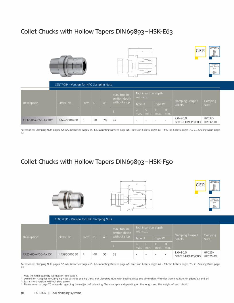
CP32-HSK-E63-A=703) 44646000700 E 50 70 47 - - - -2,0–20,0GERC32-HP/HPD/GBD
HPC32•HPC32-DI
CP25-HSK-F50-A=553) 44585000550 F 40 55 38 - - - -1,0–16,0GERC25-HP/HPD/GBD
HPC25•HPC25-DI
CENTRO|P – Version for HPC Clamping Nuts
CENTRO|P – Version for HPC Clamping Nuts
Description Order-No. Form D A 2)
max. tool in-sertion depth without stop
Tool insertion depth with stop
Clamping Range / Collets
ClampingNutsType U Type W
EG max.
G min.
H max.
H min.
Description Order-No. Form D A 2)
max. tool in-sertion depth without stop
Tool insertion depth with stop
Clamping Range / Collets
ClampingNutsType U Type W
EG max.
G min.
H max.
H min.
Accessories: Clamping Nuts pages 62, 64, Wrenches pages 65, 66, Mounting Devices page 66, Precision Collets pages 67 - 69, Tap Collets pages 70, 71, Sealing Discs page 73
Accessories: Clamping Nuts pages 62, 64, Wrenches pages 65, 66, Mounting Devices page 66, Precision Collets pages 67 - 69, Tap Collets pages 70, 71, Sealing Discs page 73
Collet Chucks with Hollow Tapers DIN 69893 – HSK-E63
Collet Chucks with Hollow Tapers DIN 69893 – HSK-F50
G ER
G ER
STANDARD
STANDARD
1) MQL (minimal quantity lubrication) see page 52) Dimension A applies to Clamping Nuts without Sealing Discs. For Clamping Nuts with Sealing Discs see dimension A1) under Clamping Nuts on pages 62 and 643) Extra short version, without stop screw4) Please refer to page 76 onwards regarding the subject of balancing. The max. rpm is depending on the length and the weight of each chuck.
U≤1gmm max. 30.000
rpm⁴)
U≤1gmm max. 30.000
rpm⁴)
D
A
E
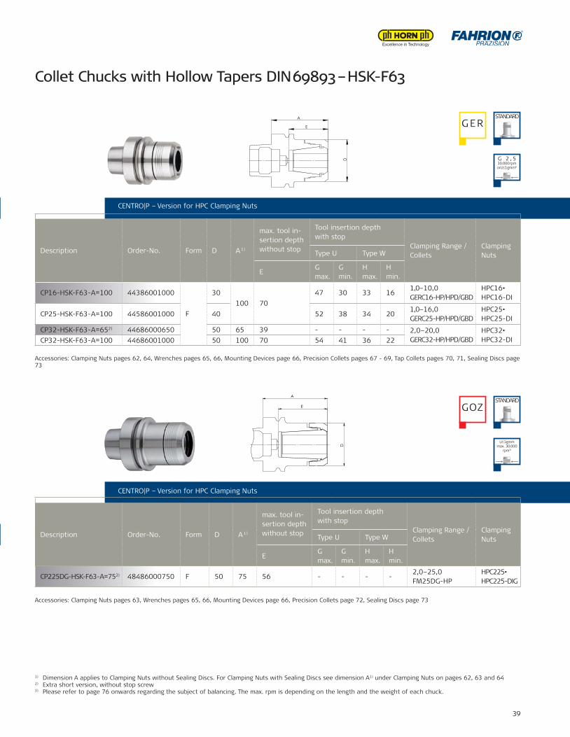
39
CP16-HSK-F63-A=100 44386001000
F
30100 70
47 30 33 161,0–10,0GERC16-HP/HPD/GBD
HPC16•HPC16-DI
CP25-HSK-F63-A=100 44586001000 40 52 38 34 201,0–16,0GERC25-HP/HPD/GBD
HPC25•HPC25-DI
CP32-HSK-F63-A=652) 44686000650 50 65 39 - - - - 2,0–20,0GERC32-HP/HPD/GBD
HPC32•HPC32-DICP32-HSK-F63-A=100 44686001000 50 100 70 54 41 36 22
CP225DG-HSK-F63-A=752) 48486000750 F 50 75 56 - - - -2,0–25,0FM25DG-HP
HPC225•HPC225-DIG
1) Dimension A applies to Clamping Nuts without Sealing Discs. For Clamping Nuts with Sealing Discs see dimension A1) under Clamping Nuts on pages 62, 63 and 642) Extra short version, without stop screw3) Please refer to page 76 onwards regarding the subject of balancing. The max. rpm is depending on the length and the weight of each chuck.
CENTRO|P – Version for HPC Clamping Nuts
Description Order-No. Form D A 1)
max. tool in-sertion depth without stop
Tool insertion depth with stop
Clamping Range / Collets
ClampingNutsType U Type W
EG max.
G min.
H max.
H min.
CENTRO|P – Version for HPC Clamping Nuts
Description Order-No. Form D A 1)
max. tool in-sertion depth without stop
Tool insertion depth with stop
Clamping Range / Collets
ClampingNutsType U Type W
EG max.
G min.
H max.
H min.
Collet Chucks with Hollow Tapers DIN 69893 – HSK-F63
Accessories: Clamping Nuts pages 62, 64, Wrenches pages 65, 66, Mounting Devices page 66, Precision Collets pages 67 - 69, Tap Collets pages 70, 71, Sealing Discs page 73
Accessories: Clamping Nuts pages 63, Wrenches pages 65, 66, Mounting Devices page 66, Precision Collets page 72, Sealing Discs page 73
G ERSTANDARD
GOZSTANDARD
CENTRO|P – Version for HPC Clamping Nuts
CENTRO|P – Version for HPC Clamping Nuts
G 2 , 530.000 rpmorU ≤ 1 gmm³)
U≤1gmm max. 30.000
rpm³)
A
D
E
A
E
D
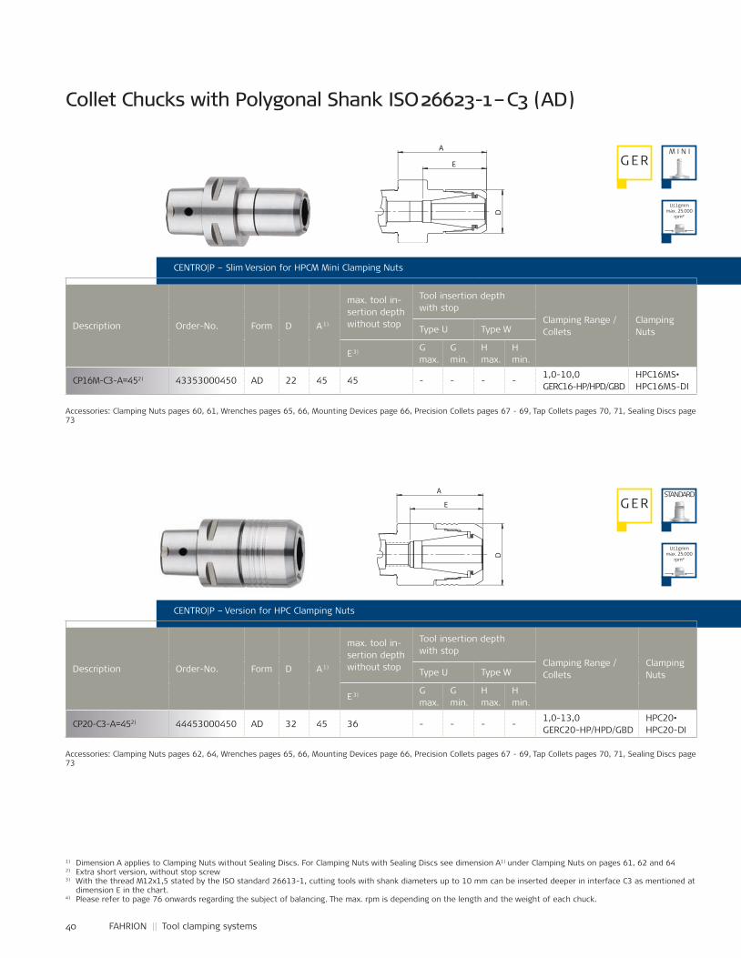
40 FAHRION || Tool clamping systems
CP16M-C3-A=452) 43353000450 AD 22 45 45 - - - -1,0-10,0GERC16-HP/HPD/GBD
HPC16MS•HPC16MS-DI
CP20-C3-A=452) 44453000450 AD 32 45 36 - - - -1,0-13,0GERC20-HP/HPD/GBD
HPC20•HPC20-DI
CENTRO|P – Slim Version for HPCM Mini Clamping Nuts
Description Order-No. Form D A 1)
max. tool in-sertion depth without stop
Tool insertion depth with stop
Clamping Range / Collets
ClampingNutsType U Type W
E 3) G max.
G min.
H max.
H min.
1) Dimension A applies to Clamping Nuts without Sealing Discs. For Clamping Nuts with Sealing Discs see dimension A1) under Clamping Nuts on pages 61, 62 and 642) Extra short version, without stop screw3) With the thread M12x1,5 stated by the ISO standard 26613-1, cutting tools with shank diameters up to 10 mm can be inserted deeper in interface C3 as mentioned at
dimension E in the chart.4) Please refer to page 76 onwards regarding the subject of balancing. The max. rpm is depending on the length and the weight of each chuck.
CENTRO|P – Version for HPC Clamping Nuts
Description Order-No. Form D A 1)
max. tool in-sertion depth without stop
Tool insertion depth with stop
Clamping Range / Collets
ClampingNutsType U Type W
E 3) G max.
G min.
H max.
H min.
Collet Chucks with Polygonal Shank ISO 26623-1 – C3 (AD)
G ER
G ERSTANDARD
M I N I
Accessories: Clamping Nuts pages 60, 61, Wrenches pages 65, 66, Mounting Devices page 66, Precision Collets pages 67 - 69, Tap Collets pages 70, 71, Sealing Discs page 73
Accessories: Clamping Nuts pages 62, 64, Wrenches pages 65, 66, Mounting Devices page 66, Precision Collets pages 67 - 69, Tap Collets pages 70, 71, Sealing Discs page 73
U≤1gmm max. 25.000
rpm⁴)
U≤1gmm max. 25.000
rpm⁴)
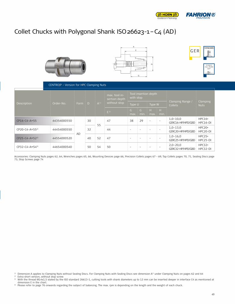
41
CP16-C4-A=55 44354000550
AD
3055
47 38 29 - -1,0–10,0GERC16-HP/HPD/GBD
HPC16•HPC16-DI
CP20-C4-A=552) 44454000550 32 44 - - - -1,0–13,0GERC20-HP/HPD/GBD
HPC20•HPC20-DI
CP25-C4-A=522) 44554000520 40 52 47 - - - -1,0–16,0GERC25-HP/HPD/GBD
HPC25•HPC25-DI
CP32-C4-A=542) 44654000540 50 54 50 - - - -2,0–20,0GERC32-HP/HPD/GBD
HPC32•HPC32-DI
CENTRO|P – Version for HPC Clamping Nuts
Description Order-No. Form D A 1)
max. tool in-sertion depth without stop
Tool insertion depth with stop
Clamping Range / Collets
ClampingNutsType U Type W
E 3) G max.
G min.
H max.
H min.
1) Dimension A applies to Clamping Nuts without Sealing Discs. For Clamping Nuts with Sealing Discs see dimension A1) under Clamping Nuts on pages 62 and 642) Extra short version, without stop screw3) With the thread M14x1,5 stated by the ISO standard 26613-1, cutting tools with shank diameters up to 12 mm can be inserted deeper in interface C4 as mentioned at
dimension E in the chart.4) Please refer to page 76 onwards regarding the subject of balancing. The max. rpm is depending on the length and the weight of each chuck.
Collet Chucks with Polygonal Shank ISO 26623-1 – C4 (AD)
G ERSTANDARD
Accessories: Clamping Nuts pages 62, 64, Wrenches pages 65, 66, Mounting Devices page 66, Precision Collets pages 67 - 69, Tap Collets pages 70, 71, Sealing Discs page 73, Stop Screws page 74
CENTRO|P – Slim Version for HPCM Mini Clamping Nuts
CENTRO|P – Version for HPC Clamping Nuts
U≤1gmm max. 25.000
rpm⁴)
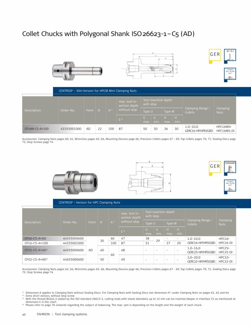
42 FAHRION || Tool clamping systems
CP16-C5-A=60 44355000600
AD
3060 47 38
29- - 1,0–10,0
GERC16-HP/HPD/GBDHPC16•HPC16-DICP16-C5-A=100 44355001000 100 87 51 37 29
CP25-C5-A=602) 44555000600 4060
48 - - - -1,0–16,0GERC25-HP/HPD/GBD
HPC25•HPC25-DI
CP32-C5-A=602) 44655000600 50 49 - - - -2,0–20,0GERC32-HP/HPD/GBD
HPC32•HPC32-DI
CP16M-C5-A=100 43355001000 AD 22 100 87 50 30 36 301,0–10,0GERC16-HP/HPD/GBD
HPC16MS•HPC16MS-DI
1) Dimension A applies to Clamping Nuts without Sealing Discs. For Clamping Nuts with Sealing Discs see dimension A1) under Clamping Nuts on pages 61, 62 and 642) Extra short version, without stop screw3) With the thread M16x1,5 stated by the ISO standard 26613-1, cutting tools with shank diameters up to 14 mm can be inserted deeper in interface C5 as mentioned at
dimension E in the chart.4) Please refer to page 76 onwards regarding the subject of balancing. The max. rpm is depending on the length and the weight of each chuck.
CENTRO|P – Version for HPC Clamping Nuts
Description Order-No. Form D A 1)
max. tool in-sertion depth without stop
Tool insertion depth with stop
Clamping Range / Collets
ClampingNutsType U Type W
E 3) G max.
G min.
H max.
H min.
G ERSTANDARD
Accessories: Clamping Nuts pages 62, 64, Wrenches pages 65, 66, Mounting Devices page 66, Precision Collets pages 67 - 69, Tap Collets pages 70, 71, Sealing Discs page 73, Stop Screws page 74
CENTRO|P – Slim Version for HPCM Mini Clamping Nuts
Description Order-No. Form D A 1)
max. tool in-sertion depth without stop
Tool insertion depth with stop
Clamping Range / Collets
ClampingNutsType U Type W
E 3) G max.
G min.
H max.
H min.
Collet Chucks with Polygonal Shank ISO 26623-1 – C5 (AD)
G ER
Accessories: Clamping Nuts pages 60, 61, Wrenches pages 65, 66, Mounting Devices page 66, Precision Collets pages 67 - 69, Tap Collets pages 70, 71, Sealing Discs page 73, Stop Screws page 74
M I N I
U≤1gmm max. 25.000
rpm⁴)
U≤1gmm max. 25.000
rpm⁴)
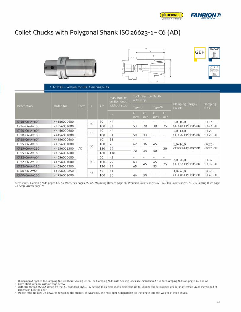
43
CP16-C6-A=602) 44356000600
AD
3060 44 - - - - 1,0–10,0
GERC16-HP/HPD/GBDHPC16•HPC16-DICP16-C6-A=100 44356001000 100 83 53 29 39 25
CP20-C6-A=602) 4445600060032
60 44 - -- -
1,0–13,0GERC20-HP/HPD/GBD
HPC20•HPC20-DICP20-C6-A=100 44456001000 100 84 59 33
CP25-C6-A=602) 44556000600
40
60 38 - -1,0–16,0GERC25-HP/HPD/GBD
HPC25•HPC25-DI
CP25-C6-A=100 44556001000 100 78 62 36 4530CP25-C6-A=130 44556001300 130 99
70 34 50CP25-C6-A=160 44556001600 160 118CP32-C6-A=602) 44656000600
5060 42 - - - -
2,0–20,0GERC32-HP/HPD/GBD
HPC32•HPC32-DI
CP32-C6-A=100 44656001000 100 79 6345
4525
CP32-C6-A=130 44656001300 130 99 65 53CP40-C6-A=652) 44756000650
6365 51 - -
- -3,0–26,0GERC40-HP/HPD/GBD
HPC40•HPC40-DICP40-C6-A=100 44756001000 100 86 46 50
1) Dimension A applies to Clamping Nuts without Sealing Discs. For Clamping Nuts with Sealing Discs see dimension A1) under Clamping Nuts on pages 62 and 642) Extra short version, without stop screw3) With the thread M20x2 stated by the ISO standard 26613-1, cutting tools with shank diameters up to 18 mm can be inserted deeper in interface C6 as mentioned at
dimension E in the chart.4) Please refer to page 76 onwards regarding the subject of balancing. The max. rpm is depending on the length and the weight of each chuck.
CENTRO|P – Version for HPC Clamping Nuts
Description Order-No. Form D A 1)
max. tool in-sertion depth without stop
Tool insertion depth with stop
Clamping Range / Collets
ClampingNutsType U Type W
E 3) G max.
G min.
H max.
H min.
Collet Chucks with Polygonal Shank ISO 26623-1 – C6 (AD)
Accessories: Clamping Nuts pages 62, 64, Wrenches pages 65, 66, Mounting Devices page 66, Precision Collets pages 67 - 69, Tap Collets pages 70, 71, Sealing Discs page 73, Stop Screws page 74
G ERSTANDARD
CENTRO|P – Version for HPC Clamping Nuts
CENTRO|P – Slim Version for HPCM Mini Clamping Nuts
G 2 , 525.000 rpmorU ≤ 1 gmm⁴)
A
E
G
H
D
Name:±0,06
±0,1
±0,2
±0,3
±0,5
±1,0
44656001000Artikel-Nr.:
Artikel-Bez. 2:Gez.Gepr.Gen.
RohteilNr.
Kanten 0,3x45°gebrochen
Passmaß Abmaß
Maßstab:
1:1
-10
10-30
30-80
80-180
180-500
500-1000
zul.Abweichg.n.tol.bearb.Maße:
Werkstoff:
Datum:05.09.11 Ca
SpannznagenfutterCP32-C6-A=100
verg. auf:Einsatztiefe:
Wärmebehandlung:
angelassen auf:
Gewicht: 1234 g
05.0
9.20
11 -
K:\S
W-A
WU
\Mod
elle
\CP-
Futt
er\Z
usam
men
stel
lung
en\C
P32\
CP-K
atal
og\4
4656
0010
00-K
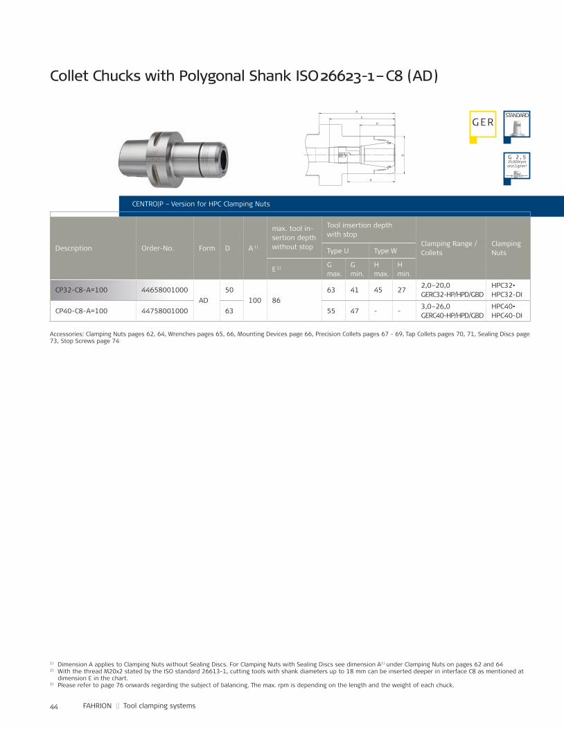
44 FAHRION || Tool clamping systems
CP32-C8-A=100 44658001000AD
50100 86
63 41 45 272,0–20,0GERC32-HP/HPD/GBD
HPC32•HPC32-DI
CP40-C8-A=100 44758001000 63 55 47 - -3,0–26,0GERC40-HP/HPD/GBD
HPC40•HPC40-DI
CENTRO|P – Version for HPC Clamping Nuts
Description Order-No. Form D A 1)
max. tool in-sertion depth without stop
Tool insertion depth with stop
Clamping Range / Collets
ClampingNutsType U Type W
E 2) G max.
G min.
H max.
H min.
Collet Chucks with Polygonal Shank ISO 26623-1 – C8 (AD)
Accessories: Clamping Nuts pages 62, 64, Wrenches pages 65, 66, Mounting Devices page 66, Precision Collets pages 67 - 69, Tap Collets pages 70, 71, Sealing Discs page 73, Stop Screws page 74
G ERSTANDARD
1) Dimension A applies to Clamping Nuts without Sealing Discs. For Clamping Nuts with Sealing Discs see dimension A1) under Clamping Nuts on pages 62 and 642) With the thread M20x2 stated by the ISO standard 26613-1, cutting tools with shank diameters up to 18 mm can be inserted deeper in interface C8 as mentioned at
dimension E in the chart.3) Please refer to page 76 onwards regarding the subject of balancing. The max. rpm is depending on the length and the weight of each chuck.
G 2 , 525.000 rpmorU ≤ 1 gmm³)
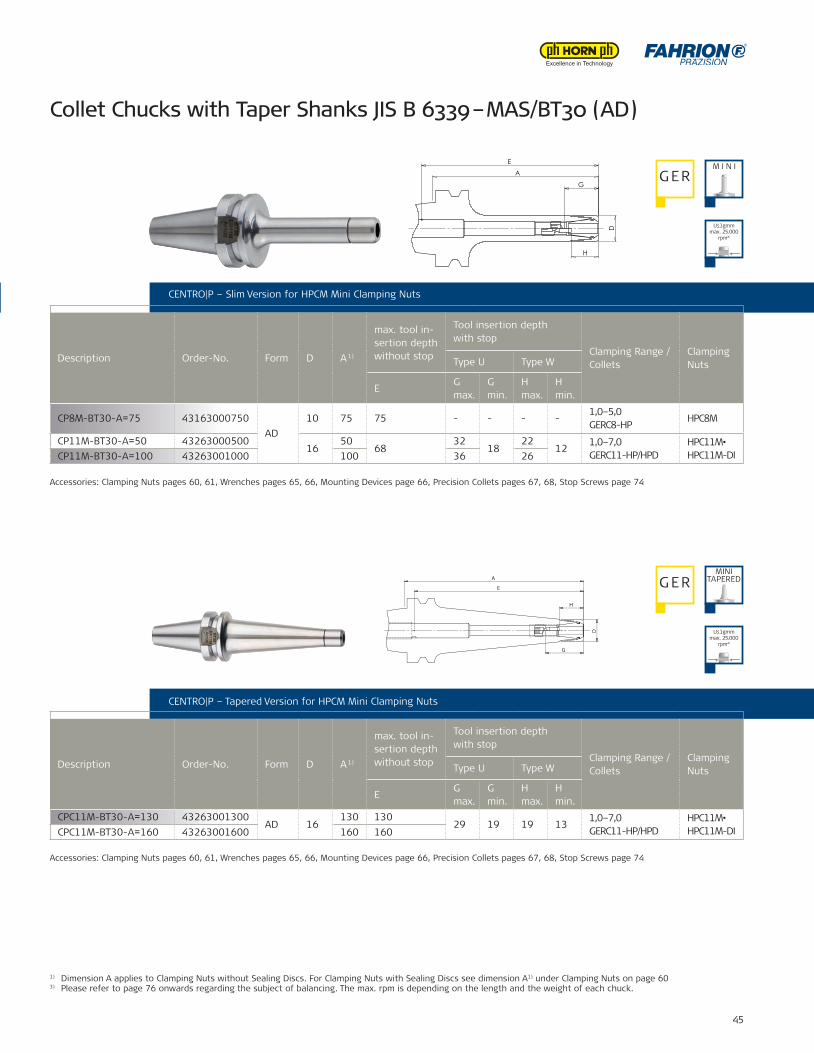
45
CP8M-BT30-A=75 43163000750AD
10 75 75 - - - -1,0–5,0GERC8-HP
HPC8M
CP11M-BT30-A=50 4326300050016
5068
3218
2212
1,0–7,0GERC11-HP/HPD
HPC11M•HPC11M-DICP11M-BT30-A=100 43263001000 100 36 26
CPC11M-BT30-A=130 43263001300AD 16
130 13029 19 19 13
1,0–7,0GERC11-HP/HPD
HPC11M•HPC11M-DICPC11M-BT30-A=160 43263001600 160 160
1) Dimension A applies to Clamping Nuts without Sealing Discs. For Clamping Nuts with Sealing Discs see dimension A1) under Clamping Nuts on page 603) Please refer to page 76 onwards regarding the subject of balancing. The max. rpm is depending on the length and the weight of each chuck.
CENTRO|P – Tapered Version for HPCM Mini Clamping Nuts
G ER
CENTRO|P – Version for HPC Clamping Nuts CENTRO|P – Slim Version for HPCM Mini Clamping Nuts
Description Order-No. Form D A 1)
max. tool in-sertion depth without stop
Tool insertion depth with stop
Clamping Range / Collets
ClampingNutsType U Type W
EG max.
G min.
H max.
H min.
Description Order-No. Form D A 1)
max. tool in-sertion depth without stop
Tool insertion depth with stop
Clamping Range / Collets
ClampingNutsType U Type W
EG max.
G min.
H max.
H min.
Accessories: Clamping Nuts pages 60, 61, Wrenches pages 65, 66, Mounting Devices page 66, Precision Collets pages 67, 68, Stop Screws page 74
Accessories: Clamping Nuts pages 60, 61, Wrenches pages 65, 66, Mounting Devices page 66, Precision Collets pages 67, 68, Stop Screws page 74
Collet Chucks with Taper Shanks JIS B 6339 – MAS/BT30 (AD)
M I N IG ER
MINITAPERED
U≤1gmm max. 25.000
rpm²)
U≤1gmm max. 25.000
rpm²)
D
A
G
H
E
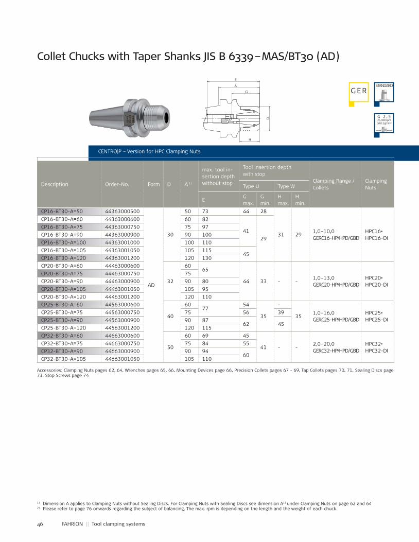
46 FAHRION || Tool clamping systems
CP16-BT30-A=50 44363000500
AD
30
50 73 44 28
31 291,0–10,0GERC16-HP/HPD/GBD
HPC16•HPC16-DI
CP16-BT30-A=60 44363000600 60 82
4129
CP16-BT30-A=75 44363000750 75 97CP16-BT30-A=90 44363000900 90 100CP16-BT30-A=100 44363001000 100 110CP16-BT30-A=105 44363001050 105 115
45CP16-BT30-A=120 44363001200 120 130CP20-BT30-A=60 44463000600
32
6065
44 33 - -1,0–13,0GERC20-HP/HPD/GBD
HPC20•HPC20-DI
CP20-BT30-A=75 44463000750 75CP20-BT30-A=90 44463000900 90 80CP20-BT30-A=105 44463001050 105 95CP20-BT30-A=120 44463001200 120 110CP25-BT30-A=60 44563000600
40
6077
54
35
-
351,0–16,0GERC25-HP/HPD/GBD
HPC25•HPC25-DI
CP25-BT30-A=75 44563000750 75 56 39CP25-BT30-A=90 44563000900 90 87
62 45CP25-BT30-A=120 44563001200 120 115CP32-BT30-A=60 44663000600
50
60 69 45
41 - -2,0–20,0GERC32-HP/HPD/GBD
HPC32•HPC32-DI
CP32-BT30-A=75 44663000750 75 84 55CP32-BT30-A=90 44663000900 90 94
60CP32-BT30-A=105 44663001050 105 110
1) Dimension A applies to Clamping Nuts without Sealing Discs. For Clamping Nuts with Sealing Discs see dimension A1) under Clamping Nuts on page 62 and 642) Please refer to page 76 onwards regarding the subject of balancing. The max. rpm is depending on the length and the weight of each chuck.
CENTRO|P – Version for HPC Clamping Nuts
Description Order-No. Form D A 1)
max. tool in-sertion depth without stop
Tool insertion depth with stop
Clamping Range / Collets
ClampingNutsType U Type W
EG max.
G min.
H max.
H min.
Collet Chucks with Taper Shanks JIS B 6339 – MAS/BT30 (AD)
Accessories: Clamping Nuts pages 62, 64, Wrenches pages 65, 66, Mounting Devices page 66, Precision Collets pages 67 - 69, Tap Collets pages 70, 71, Sealing Discs page 73, Stop Screws page 74
G ERSTANDARD
G 2 , 525.000 rpmorU ≤ 1 gmm²)
A
D
G
H
E
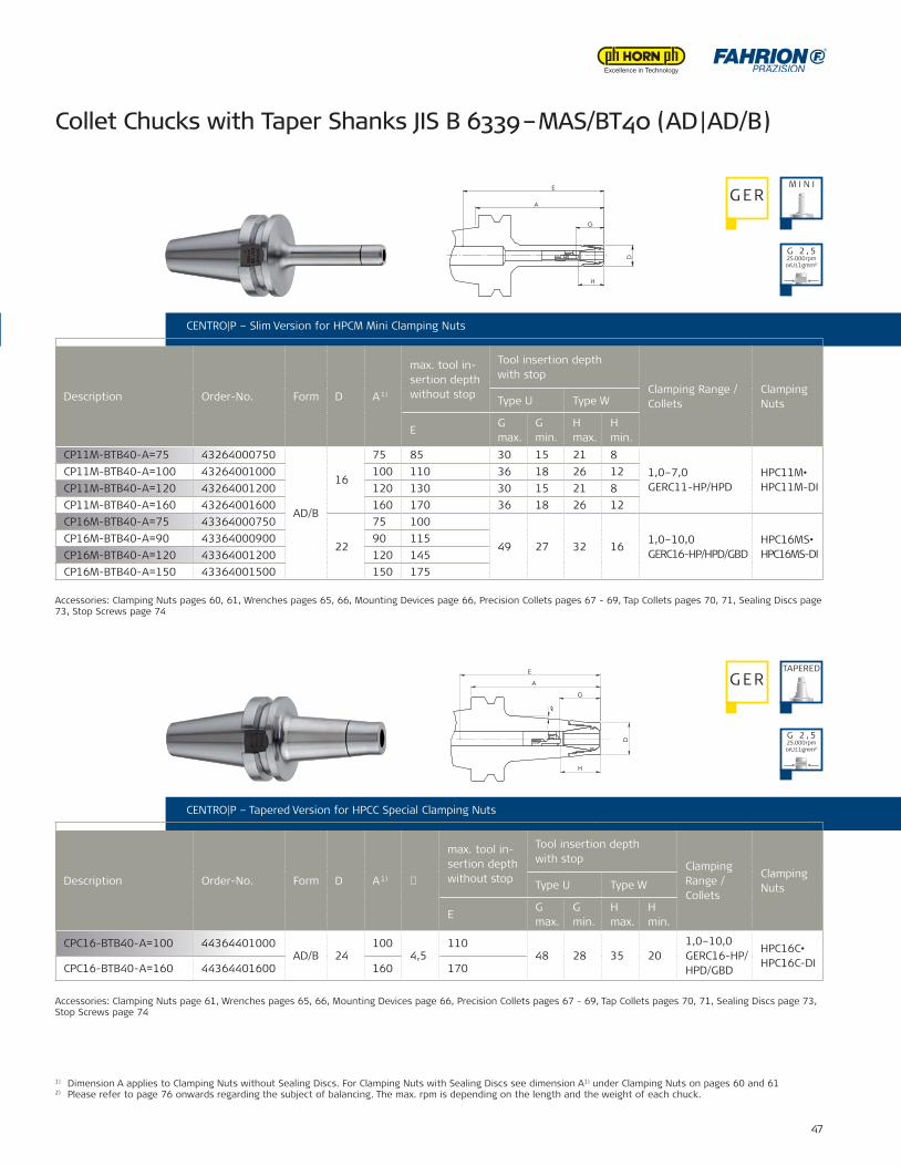
47
CP11M-BTB40-A=75 43264000750
AD/B
16
75 85 30 15 21 81,0–7,0GERC11-HP/HPD
HPC11M•HPC11M-DI
CP11M-BTB40-A=100 43264001000 100 110 36 18 26 12CP11M-BTB40-A=120 43264001200 120 130 30 15 21 8CP11M-BTB40-A=160 43264001600 160 170 36 18 26 12CP16M-BTB40-A=75 43364000750
22
75 100
49 27 32 161,0–10,0GERC16-HP/HPD/GBD
HPC16MS•HPC16MS-DI
CP16M-BTB40-A=90 43364000900 90 115CP16M-BTB40-A=120 43364001200 120 145CP16M-BTB40-A=150 43364001500 150 175
CPC16-BTB40-A=100 44364401000AD/B 24
1004,5
11048 28 35 20
1,0–10,0GERC16-HP/HPD/GBD
HPC16C•HPC16C-DICPC16-BTB40-A=160 44364401600 160 170
1) Dimension A applies to Clamping Nuts without Sealing Discs. For Clamping Nuts with Sealing Discs see dimension A1) under Clamping Nuts on pages 60 and 612) Please refer to page 76 onwards regarding the subject of balancing. The max. rpm is depending on the length and the weight of each chuck.
CENTRO|P – Slim Version for HPCM Mini Clamping Nuts
Description Order-No. Form D A 1)
max. tool in-sertion depth without stop
Tool insertion depth with stop
Clamping Range / Collets
ClampingNutsType U Type W
EG max.
G min.
H max.
H min.
CENTRO|P – Version for HPC Clamping Nuts
CENTRO|P – Tapered Version for HPCC Special Clamping Nuts
Description Order-No. Form D A 1) �
max. tool in-sertion depth without stop
Tool insertion depth with stop
Clamping Range / Collets
ClampingNutsType U Type W
EG max.
G min.
H max.
H min.
Collet Chucks with Taper Shanks JIS B 6339 – MAS/BT40 (AD | AD/B)
Accessories: Clamping Nuts pages 60, 61, Wrenches pages 65, 66, Mounting Devices page 66, Precision Collets pages 67 - 69, Tap Collets pages 70, 71, Sealing Discs page 73, Stop Screws page 74
Accessories: Clamping Nuts page 61, Wrenches pages 65, 66, Mounting Devices page 66, Precision Collets pages 67 - 69, Tap Collets pages 70, 71, Sealing Discs page 73, Stop Screws page 74
M I N IG ER
G ERTAPERED
G 2 , 525.000 rpmorU ≤ 1 gmm²)
G 2 , 525.000 rpmorU ≤ 1 gmm²)
D
H
G
A
E
D
H
G
A
∝
E
Name:±0,06
±0,1
±0,2
±0,3
±0,5
±1,0
44364401000Artikel-Nr.:
Artikel-Bez. 2:Gez.Gepr.Gen.
RohteilNr.
Kanten 0,3x45°gebrochen
Passmaß Abmaß
Maßstab:
1:1
-10
10-30
30-80
80-180
180-500
500-1000
zul.Abweichg.n.tol.bearb.Maße:
Werkstoff:
Datum:29.05.07 Ho
SapnnzangenfutterCPC16-BTB40-A=100
verg. auf:Einsatztiefe:
Wärmebehandlung:
angelassen auf:
Gewicht: g
03.0
3.20
14 -
C:\F
AH
RIO
N-P
DM
\Mod
elle
\CP
C-F
utte
r\Zus
amm
enst
ellu
ngen
\CP
C16
\CP
-Kat
alog
\443
6440
1000
-K
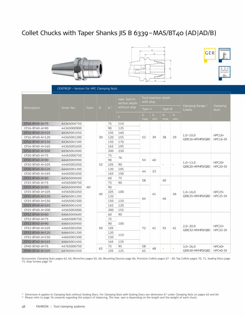
48 FAHRION || Tool clamping systems
1) Dimension A applies to Clamping Nuts without Sealing Discs. For Clamping Nuts with Sealing Discs see dimension A1) under Clamping Nuts on pages 62 and 642) Please refer to page 76 onwards regarding the subject of balancing. The max. rpm is depending on the length and the weight of each chuck.
CENTRO|P – Version for HPC Clamping Nuts
Description Order-No. Form D A 1)
max. tool in-sertion depth without stop
Tool insertion depth with stop
Clamping Range / Collets
ClampingNutsType U Type W
EG max.
G min.
H max.
H min.
Collet Chucks with Taper Shanks JIS B 6339 – MAS/BT40 (AD | AD/B)
Accessories: Clamping Nuts pages 62, 64, Wrenches pages 65, 66, Mounting Devices page 66, Precision Collets pages 67 - 69, Tap Collets pages 70, 71, Sealing Discs page 73, Stop Screws page 74
G ERSTANDARD
G 2 , 525.000 rpmorU ≤ 1 gmm²)
CP16-BT40-A=75 44365000750
AD
30
75 110
52 39 38 291,0–10,0GERC16-HP/HPD/GBD
HPC16•HPC16-DI
CP16-BT40-A=90 44365000900 90 125CP16-BT40-A=105 44365001050 105 140CP16-BT40-A=120 44365001200 120 155CP16-BT40-A=150 44365001500 150 170CP16-BT40-A=165 44365001650 165 195CP16-BT40-A=200 44365002000 200 230CP20-BT40-A=75 44465000750
32
7576
53 40- -
1,0–13,0GERC20-HP/HPD/GBD
HPC20•HPC20-DI
CP20-BT40-A=90 44465000900 90CP20-BT40-A=105 44465001050 105 90CP20-BT40-A=120 44465001200 120 105
44 33CP20-BT40-A=165 44465001650 165 150CP25-BT40-A=60 44565000600
40
60 7558
41
40
361,0–16,0GERC25-HP/HPD/GBD
HPC25•HPC25-DI
CP25-BT40-A=75 44565000750 75 90CP25-BT40-A=90 44565000900 90
100
64 46
CP25-BT40-A=105 44565001050 105CP25-BT40-A=120 44565001200 120CP25-BT40-A=150 44565001500 150 110CP25-BT40-A=165 44565001650 165 120CP25-BT40-A=200 44565002000 200 155CP32-BT40-A=60 44665000600
50
60 90
72 41 55 412,0–20,0GERC32-HP/HPD/GBD
HPC32•HPC32-DI
CP32-BT40-A=75 44665000750 75100CP32-BT40-A=90 44665000900 90
CP32-BT40-A=105 44665001050 105CP32-BT40-A=120 44665001200 120
110CP32-BT40-A=150 44665001500 150CP32-BT40-A=165 44665001650 165 135CP40-BT40-A=75 44765000750
6375 95 58
48 - -3,0–26,0GERC40-HP/HPD/GBD
HPC40•HPC40-DICP40-BT40-A=105 44765001050 105 125 65
A
H
D
G
E
Name:±0,06
±0,1
±0,2
±0,3
±0,5
±1,0
44664000700Artikel-Nr.:
Artikel-Bez. 2:Gez.Gepr.Gen.
RohteilNr.
Kanten 0,3x45°gebrochen
Passmaß Abmaß
Maßstab:
1:1
-10
10-30
30-80
80-180
180-500
500-1000
zul.Abweichg.n.tol.bearb.Maße:
Werkstoff:
Datum:05.09.11 Ca
SpannzangenfutterCP32-BTB40-A=70
verg. auf:Einsatztiefe:
Wärmebehandlung:
angelassen auf:
Gewicht: 1234 g13
.09.
2011
- K:
\SW
-AW
U\M
odel
le\C
P-Fu
tter
\Zus
amm
enst
ellu
ngen
\CP3
2\CP
-Kat
alog
\446
6400
0700
-K
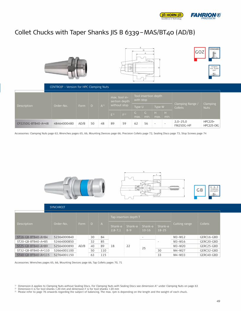
49
CP225DG-BTB40-A=48 48464000480 AD/B 50 48 89 59 62 56 - -2,0–25,0FM25DG-HP
HPC225•HPC225-DIG
ST16-GB-BTB40-A=84 52364000840
AD/B
30 84
18 22
--
M3–M12 GERC16-GBDST20-GB-BTB40-A=85 52464000850 32 85
25
M3–M16 GERC20-GBDST25-GB-BTB40-A=89 52564000890 40 89 M3–M20 GERC25-GBDST32-GB-BTB40-A=110 52664001100 50 110 30 M4–M27 GERC32-GBDST40-GB-BTB40-A=115 52764001150 63 115 33 M4–M33 GERC40-GBD
CENTRO|P – Version for HPC Clamping Nuts
Collet Chucks with Taper Shanks JIS B 6339 – MAS/BT40 (AD/B)
Accessories: Clamping Nuts page 63, Wrenches pages 65, 66, Mounting Devices page 66, Precision Collets page 72, Sealing Discs page 73, Stop Screws page 74
Accessories: Wrenches pages 65, 66, Mounting Devices page 66, Tap Collets pages 70, 71
CENTRO|P – Version for HPC Clamping Nuts
Description Order-No. Form D A 1)
max. tool in-sertion depth without stop
Tool insertion depth with stop
Clamping Range / Collets
ClampingNutsType U Type W
E 2) F 2) G max.
G min.
H max.
H min.
SYNCHRO|T
Description Order-No. Form D A
Tap insertion depth T
Cutting range ColletsShank-ø2,8-7,1
Shank-ø8-9
Shank-ø10-16
Shank-ø18-25
1) Dimension A applies to Clamping Nuts without Sealing Discs. For Clamping Nuts with Sealing Discs see dimension A1) under Clamping Nuts on page 632) Dimension E is for tool shanks ≤ 20 mm and dimension F is for tool shanks > 20 mm3) Please refer to page 76 onwards regarding the subject of balancing. The max. rpm is depending on the length and the weight of each chuck.
GOZSTANDARD
G B
U≤1gmm max. 25.000
rpm³)
G 6 , 312.000 rpmorU ≤ 1 gmm³)
A
D
E
G
F
Name:
48464000480Artikel-Nr.:
Artikel-Bez. 2:Gez.Gepr.Gen.
RohteilNr.
Maßstab:
1:1
Werkstoff:
Datum:31.08.11 Ho
SpannzangenfutterCP225DG-BTB50-A=48
verg. auf:Einsatztiefe:
Wärmebehandlung:
angelassen auf:
Gewicht: g
05.0
9.20
11 -
K:\S
W-A
WU
\Mod
elle
\CP-
Futt
er\Z
usam
men
stel
lung
en\C
P225
DG
\Kat
alog
\484
6400
0480
-K
T
D
A
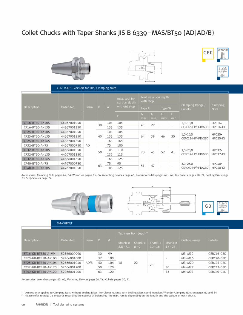
50 FAHRION || Tool clamping systems
ST16-GB-BTB50-A=99 52366000990
AD/B
30 99
18 22
--
M3–M12 GERC16-GBDST20-GB-BTB50-A=100 52466001000 32 100
25
M3–M16 GERC20-GBDST25-GB-BTB50-A=104 52566001040 40 104 M3–M20 GERC25-GBDST32-GB-BTB50-A=120 52666001200 50 120 30 M4–M27 GERC32-GBDST40-GB-BTB50-A=120 52766001200 63 120 33 M4–M33 GERC40-GBD
CP16-BT50-A=105 44367001050
AD
30105 105
43 29 - -1,0–10,0GERC16-HP/HPD/GBD
HPC16•HPC16-DICP16-BT50-A=135 44367001350 135 135
CP25-BT50-A=105 4456700105040
105 10564 39 46 35
1,0–16,0GERC25-HP/HPD/GBD
HPC25•HPC25-DI
CP25-BT50-A=135 44567001350 135 135CP25-BT50-A=165 44567001650 165 165CP32-BT50-A=75 44667000750
50
75 100
70 45 52 412,0–20,0GERC32-HP/HPD/GBD
HPC32•HPC32-DI
CP32-BT50-A=105 44666001050 105 110CP32-BT50-A=135 44667001350 135 115CP32-BT50-A=165 44666001650 165 125CP40-BT50-A=75 44767000750
6375 95
51 47 - -3,0–26,0GERC40-HP/HPD/GBD
HPC40•HPC40-DICP40-BT50-A=105 44767001050 105 125
1) Dimension A applies to Clamping Nuts without Sealing Discs. For Clamping Nuts with Sealing Discs see dimension A1) under Clamping Nuts on pages 62 and 642) Please refer to page 76 onwards regarding the subject of balancing. The max. rpm is depending on the length and the weight of each chuck.
CENTRO|P – Version for HPC Clamping Nuts
Description Order-No. Form D A 1)
max. tool in-sertion depth without stop
Tool insertion depth with stop
Clamping Range / Collets
ClampingNutsType U Type W
EG max.
G min.
H max.
H min.
SYNCHRO|T
Description Order-No. Form D A
Tap insertion depth T
Cutting range ColletsShank-ø2,8 – 7,1
Shank-ø8 – 9
Shank-ø10 – 16
Shank-ø18 – 25
Accessories: Clamping Nuts pages 62, 64, Wrenches pages 65, 66, Mounting Devices page 66, Precision Collets pages 67 - 69, Tap Collets pages 70, 71, Sealing Discs page 73, Stop Screws page 74
Accessories: Wrenches pages 65, 66, Mounting Devices page 66, Tap Collets pages 70, 71
Collet Chucks with Taper Shanks JIS B 6339 – MAS/BT50 (AD | AD/B)
G ERSTANDARD
G B
G 2 , 525.000 rpmorU ≤ 1 gmm²)
G 6 , 312.000 rpmorU ≤ 1 gmm²)
A
D
H
G
E
T
D
A
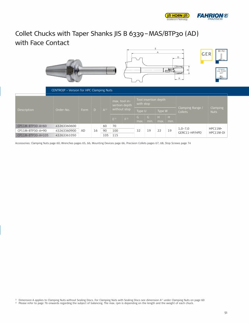
51
CENTRO|P – Version for HPC Clamping Nuts
SYNCHRO|T
Accessories: Wrenches pages 65, 66, Mounting Devices page 66, Tap Collets pages 70, 71
CP11M-BTP30-A=60 43263360600AD 16
60 7032 19 22 19
1,0–7,0GERC11-HP/HPD
HPC11M•HPC11M-DICP11M-BTP30-A=90 43263360900 90 100
CP11M-BTP30-A=105 43263361050 105 115
D
A
G
H
E
03.0
5.20
16 -
C:\f
ahrio
n-pd
m\m
odel
le\c
p-fu
tter\z
usam
men
stel
lung
en\c
p11m
\cp-
kata
log\
4326
3361
000-
K
Oberfläche:
Benennung:A4
-0,3
Projektion:
±0,3±0,5±1,0
>80-180:>180-500:>500-1000:
Weitergabe sowie auch auszugsweise Vervielfältigungdieses Dokuments, Verwertung und Mitteilung seinesInhalts sind verboten, soweit nicht ausdrücklich gestat-tet. Zuwiderhandlungen verpflichten zu Schadenser-satz. Alle Rechte für den Fall der Patent-,Gebrauchs-muster- o. Geschmacksmustereintragung vorbehalten.Schutzvermerk nach DIN 34 / ISO 16016 beachten!
Änd. M.:Rev.: Änderung:Name: Datum: kommt
vor:
1/1Blatt:
Revision:
Rohteil-Nr.:
Werkstückkanten:
IN ARBEIT
43263361000
PDM-Status:
CP11M-BT30-A=100
angelassen auf:
Wärmebehandlung:
Einsatztiefe:
vergütet auf:
SpannzangenfutterCavallaro31.08.2011
Datum:
Werkstoff:
zul. Abweichung nicht tolerierter Maße:
>0-10:>10-30:>30-80:
1:1Maßstab:
Freigegeben:Erstellt:
Artikel-Bez. 2:Artikel-Nr.:
±0,06±0,1±0,2
Name:
Fertigung in:
Format:
Collet Chucks with Taper Shanks JIS B 6339 – MAS/BTP30 (AD) with Face Contact
CENTRO|P – Version for HPC Clamping Nuts
Description Order-No. Form D A 1)
max. tool in-sertion depth without stop
Tool insertion depth with stop
Clamping Range / Collets
ClampingNutsType U Type W
E 2) F 2) G max.
G min.
H max.
H min.
U≤1gmm max. 25.000
rpm²)
Accessories: Clamping Nuts page 60, Wrenches pages 65, 66, Mounting Devices page 66, Precision Collets pages 67, 68, Stop Screws page 74
1) Dimension A applies to Clamping Nuts without Sealing Discs. For Clamping Nuts with Sealing Discs see dimension A1) under Clamping Nuts on page 602) Please refer to page 76 onwards regarding the subject of balancing. The max. rpm is depending on the length and the weight of each chuck.
M I N IG ER
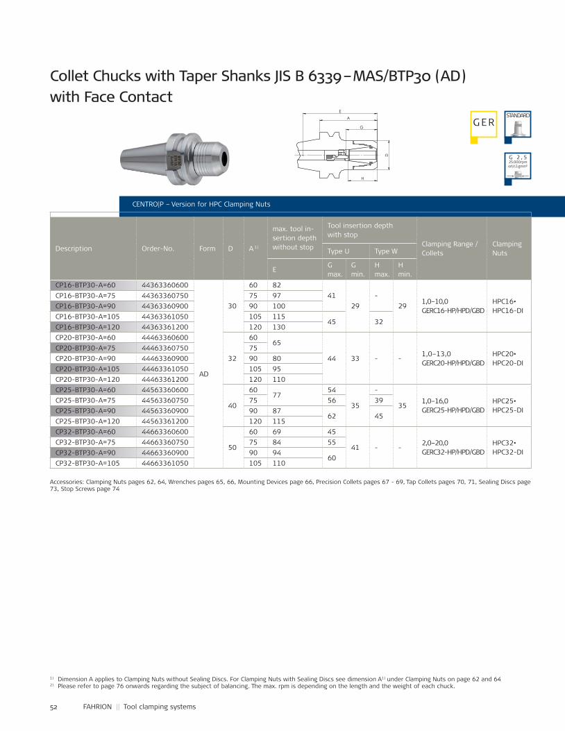
52 FAHRION || Tool clamping systems
CP16-BTP30-A=60 44363360600
AD
30
60 8241
29-
291,0–10,0GERC16-HP/HPD/GBD
HPC16•HPC16-DI
CP16-BTP30-A=75 44363360750 75 97CP16-BTP30-A=90 44363360900 90 100CP16-BTP30-A=105 44363361050 105 115
45 32CP16-BTP30-A=120 44363361200 120 130CP20-BTP30-A=60 44463360600
32
6065
44 33 - -1,0–13,0GERC20-HP/HPD/GBD
HPC20•HPC20-DI
CP20-BTP30-A=75 44463360750 75CP20-BTP30-A=90 44463360900 90 80CP20-BTP30-A=105 44463361050 105 95CP20-BTP30-A=120 44463361200 120 110CP25-BTP30-A=60 44563360600
40
6077
54
35
-
351,0–16,0GERC25-HP/HPD/GBD
HPC25•HPC25-DI
CP25-BTP30-A=75 44563360750 75 56 39CP25-BTP30-A=90 44563360900 90 87
62 45CP25-BTP30-A=120 44563361200 120 115CP32-BTP30-A=60 44663360600
50
60 69 45
41 - -2,0–20,0GERC32-HP/HPD/GBD
HPC32•HPC32-DI
CP32-BTP30-A=75 44663360750 75 84 55CP32-BTP30-A=90 44663360900 90 94
60CP32-BTP30-A=105 44663361050 105 110
A
D
G
H
E
03.0
5.20
16 -
C:\F
AHR
ION
-PD
M\m
odel
le\c
p-fu
tter\z
usam
men
stel
lung
en\c
p16u
.cp1
6m\c
p16\
CP-
Kata
log\
4436
3360
600-
K
Oberfläche:
Benennung:A4
-0,3
Projektion:
±0,3±0,5±1,0
>80-180:>180-500:>500-1000:
Weitergabe sowie auch auszugsweise Vervielfältigungdieses Dokuments, Verwertung und Mitteilung seinesInhalts sind verboten, soweit nicht ausdrücklich gestat-tet. Zuwiderhandlungen verpflichten zu Schadenser-satz. Alle Rechte für den Fall der Patent-,Gebrauchs-muster- o. Geschmacksmustereintragung vorbehalten.Schutzvermerk nach DIN 34 / ISO 16016 beachten!
Änd. M.:Rev.: Änderung:Name: Datum: kommt
vor:
1/1Blatt:
Revision:
Rohteil-Nr.:
Werkstückkanten:
IN ARBEIT
44363360600
PDM-Status:
CP16-BT30-A=60
angelassen auf:
Wärmebehandlung:
Einsatztiefe:
vergütet auf:
SpannzangenfutterTrentzsch03.05.2016
Datum:
Werkstoff:
zul. Abweichung nicht tolerierter Maße:
>0-10:>10-30:>30-80:
1:1Maßstab:
Freigegeben:Erstellt:
Artikel-Bez. 2:Artikel-Nr.:
±0,06±0,1±0,2
Name:
Fertigung in:
Format:
CENTRO|P – Version for HPC Clamping Nuts
Description Order-No. Form D A 1)
max. tool in-sertion depth without stop
Tool insertion depth with stop
Clamping Range / Collets
ClampingNutsType U Type W
EG max.
G min.
H max.
H min.
Collet Chucks with Taper Shanks JIS B 6339 – MAS/BTP30 (AD) with Face Contact
G ERSTANDARD
G 2 , 525.000 rpmorU ≤ 1 gmm²)
Accessories: Clamping Nuts pages 62, 64, Wrenches pages 65, 66, Mounting Devices page 66, Precision Collets pages 67 - 69, Tap Collets pages 70, 71, Sealing Discs page 73, Stop Screws page 74
1) Dimension A applies to Clamping Nuts without Sealing Discs. For Clamping Nuts with Sealing Discs see dimension A1) under Clamping Nuts on page 62 and 642) Please refer to page 76 onwards regarding the subject of balancing. The max. rpm is depending on the length and the weight of each chuck.
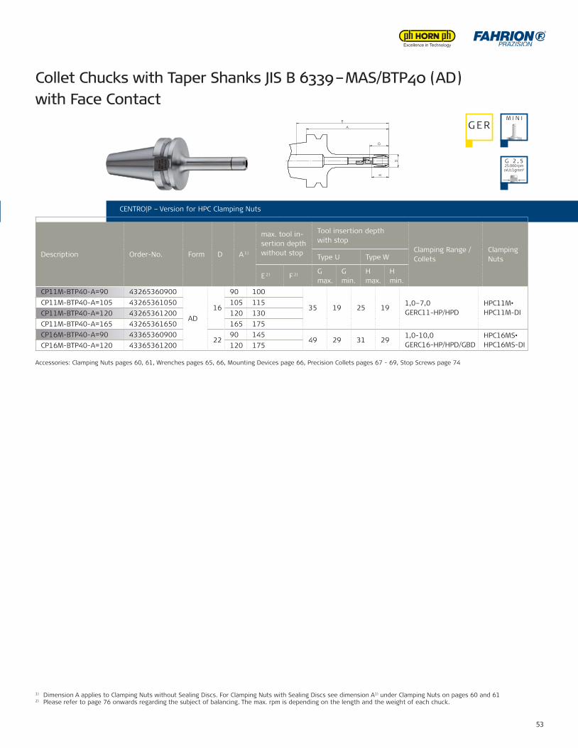
53
CP11M-BTP40-A=90 43265360900
AD16
90 100
35 19 25 191,0–7,0GERC11-HP/HPD
HPC11M•HPC11M-DI
CP11M-BTP40-A=105 43265361050 105 115CP11M-BTP40-A=120 43265361200 120 130CP11M-BTP40-A=165 43265361650 165 175CP16M-BTP40-A=90 43365360900
2290 145
49 29 31 291,0-10,0 GERC16-HP/HPD/GBD
HPC16MS•HPC16MS-DICP16M-BTP40-A=120 43365361200 120 175
D
H
G
A
E
03.0
5.20
16 -
C:\f
ahrio
n-pd
m\m
odel
le\c
p-fu
tter\z
usam
men
stel
lung
en\c
p11m
\cp-
kata
log\
4326
4361
000-
K
Oberfläche:
Benennung:A4
-0,3
Projektion:
±0,3±0,5±1,0
>80-180:>180-500:>500-1000:
Weitergabe sowie auch auszugsweise Vervielfältigungdieses Dokuments, Verwertung und Mitteilung seinesInhalts sind verboten, soweit nicht ausdrücklich gestat-tet. Zuwiderhandlungen verpflichten zu Schadenser-satz. Alle Rechte für den Fall der Patent-,Gebrauchs-muster- o. Geschmacksmustereintragung vorbehalten.Schutzvermerk nach DIN 34 / ISO 16016 beachten!
Änd. M.:Rev.: Änderung:Name: Datum: kommt
vor:
1/1Blatt:
Revision:
Rohteil-Nr.:
Werkstückkanten:
IN ARBEIT
43264361000
PDM-Status:
CP11M-BTB40-A=100
angelassen auf:
Wärmebehandlung:
Einsatztiefe:
vergütet auf:
SpannzangenfutterTrentzsch02.05.2016
Datum:
Werkstoff:
zul. Abweichung nicht tolerierter Maße:
>0-10:>10-30:>30-80:
1:1Maßstab:
Freigegeben:Erstellt:
Artikel-Bez. 2:Artikel-Nr.:
±0,06±0,1±0,2
Name:
Fertigung in:
Format:
CENTRO|P – Version for HPC Clamping Nuts
Collet Chucks with Taper Shanks JIS B 6339 – MAS/BTP40 (AD) with Face Contact
CENTRO|P – Version for HPC Clamping Nuts
Description Order-No. Form D A 1)
max. tool in-sertion depth without stop
Tool insertion depth with stop
Clamping Range / Collets
ClampingNutsType U Type W
E 2) F 2) G max.
G min.
H max.
H min.
Accessories: Clamping Nuts pages 60, 61, Wrenches pages 65, 66, Mounting Devices page 66, Precision Collets pages 67 - 69, Stop Screws page 74
1) Dimension A applies to Clamping Nuts without Sealing Discs. For Clamping Nuts with Sealing Discs see dimension A1) under Clamping Nuts on pages 60 and 612) Please refer to page 76 onwards regarding the subject of balancing. The max. rpm is depending on the length and the weight of each chuck.
M I N IG ER
G 2 , 525.000 rpmorU ≤ 1 gmm²)
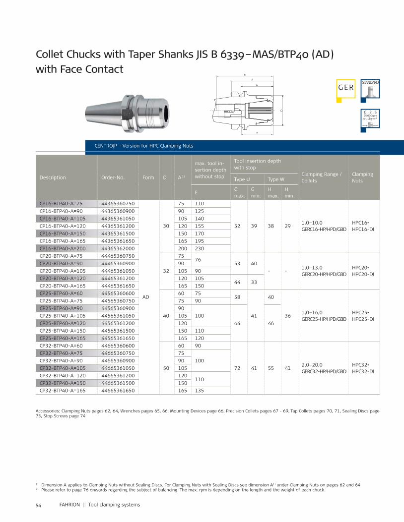
54 FAHRION || Tool clamping systems
CP16-BTP40-A=75 44365360750
AD
30
75 110
52 39 38 291,0–10,0GERC16-HP/HPD/GBD
HPC16•HPC16-DI
CP16-BTP40-A=90 44365360900 90 125CP16-BTP40-A=105 44365361050 105 140CP16-BTP40-A=120 44365361200 120 155CP16-BTP40-A=150 44365361500 150 170CP16-BTP40-A=165 44365361650 165 195CP16-BTP40-A=200 44365362000 200 230CP20-BTP40-A=75 44465360750
32
7576
53 40- -
1,0–13,0GERC20-HP/HPD/GBD
HPC20•HPC20-DI
CP20-BTP40-A=90 44465360900 90CP20-BTP40-A=105 44465361050 105 90CP20-BTP40-A=120 44465361200 120 105
44 33CP20-BTP40-A=165 44465361650 165 150CP25-BTP40-A=60 44565360600
40
60 7558
41
40
361,0–16,0GERC25-HP/HPD/GBD
HPC25•HPC25-DI
CP25-BTP40-A=75 44565360750 75 90CP25-BTP40-A=90 44565360900 90
10064 46
CP25-BTP40-A=105 44565361050 105CP25-BTP40-A=120 44565361200 120CP25-BTP40-A=150 44565361500 150 110CP25-BTP40-A=165 44565361650 165 120CP32-BTP40-A=60 44665360600
50
60 90
72 41 55 412,0–20,0GERC32-HP/HPD/GBD
HPC32•HPC32-DI
CP32-BTP40-A=75 44665360750 75100CP32-BTP40-A=90 44665360900 90
CP32-BTP40-A=105 44665361050 105CP32-BTP40-A=120 44665361200 120
110CP32-BTP40-A=150 44665361500 150CP32-BTP40-A=165 44665361650 165 135
G
D
H
A
E
03.0
5.20
16 -
C:\F
AHR
ION
-PD
M\m
odel
le\c
p-fu
tter\z
usam
men
stel
lung
en\c
p32\
cp-k
atal
og\4
4665
3607
00-K
Oberfläche:
Benennung:A4
-0,3
Projektion:
±0,3±0,5±1,0
>80-180:>180-500:>500-1000:
Weitergabe sowie auch auszugsweise Vervielfältigungdieses Dokuments, Verwertung und Mitteilung seinesInhalts sind verboten, soweit nicht ausdrücklich gestat-tet. Zuwiderhandlungen verpflichten zu Schadenser-satz. Alle Rechte für den Fall der Patent-,Gebrauchs-muster- o. Geschmacksmustereintragung vorbehalten.Schutzvermerk nach DIN 34 / ISO 16016 beachten!
Änd. M.:Rev.: Änderung:Name: Datum: kommt
vor:
1/1Blatt:
Revision:
Rohteil-Nr.:
Werkstückkanten:
IN ARBEIT
44665360700
PDM-Status:
CP32-BT40-A=70
angelassen auf:
Wärmebehandlung:
Einsatztiefe:
vergütet auf:
SpannzangenfutterTrentzsch03.05.2016
Datum:
Werkstoff:
zul. Abweichung nicht tolerierter Maße:
>0-10:>10-30:>30-80:
1:1Maßstab:
Freigegeben:Erstellt:
Artikel-Bez. 2:Artikel-Nr.:
±0,06±0,1±0,2
Name:
Fertigung in:
Format:
CENTRO|P – Version for HPC Clamping Nuts
Description Order-No. Form D A 1)
max. tool in-sertion depth without stop
Tool insertion depth with stop
Clamping Range / Collets
ClampingNutsType U Type W
EG max.
G min.
H max.
H min.
Collet Chucks with Taper Shanks JIS B 6339 – MAS/BTP40 (AD) with Face Contact
G ERSTANDARD
G 2 , 525.000 rpmorU ≤ 1 gmm²)
Accessories: Clamping Nuts pages 62, 64, Wrenches pages 65, 66, Mounting Devices page 66, Precision Collets pages 67 - 69, Tap Collets pages 70, 71, Sealing Discs page 73, Stop Screws page 74
1) Dimension A applies to Clamping Nuts without Sealing Discs. For Clamping Nuts with Sealing Discs see dimension A1) under Clamping Nuts on pages 62 and 642) Please refer to page 76 onwards regarding the subject of balancing. The max. rpm is depending on the length and the weight of each chuck.
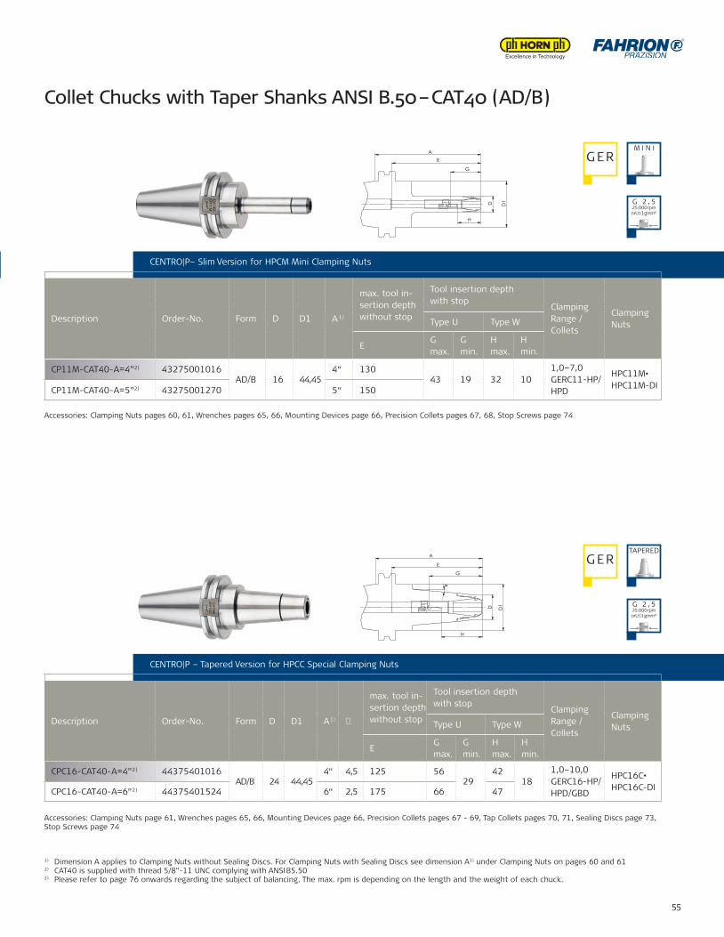
55
CP11M-CAT40-A=4”2) 43275001016AD/B 16 44,45
4“ 13043 19 32 10
1,0–7,0GERC11-HP/HPD
HPC11M•HPC11M-DICP11M-CAT40-A=5”2) 43275001270 5“ 150
CPC16-CAT40-A=4”2) 44375401016AD/B 24 44,45
4“ 4,5 125 5629
4218
1,0–10,0GERC16-HP/HPD/GBD
HPC16C•HPC16C-DICPC16-CAT40-A=6”2) 44375401524 6“ 2,5 175 66 47
1) Dimension A applies to Clamping Nuts without Sealing Discs. For Clamping Nuts with Sealing Discs see dimension A1) under Clamping Nuts on pages 60 and 612) CAT40 is supplied with thread 5/8”-11 UNC complying with ANSI B5.503) Please refer to page 76 onwards regarding the subject of balancing. The max. rpm is depending on the length and the weight of each chuck.
CENTRO|P– Slim Version for HPCM Mini Clamping Nuts
Description Order-No. Form D D1 A 1)
max. tool in-sertion depth without stop
Tool insertion depth with stop
Clamping Range / Collets
ClampingNutsType U Type W
E G max.
G min.
H max.
H min.
Accessories: Clamping Nuts pages 60, 61, Wrenches pages 65, 66, Mounting Devices page 66, Precision Collets pages 67, 68, Stop Screws page 74
CENTRO|P – Tapered Version for HPCC Special Clamping Nuts
Description Order-No. Form D D1 A 1) �
max. tool in-sertion depth without stop
Tool insertion depth with stop
Clamping Range / Collets
ClampingNutsType U Type W
E G max.
G min.
H max.
H min.
Accessories: Clamping Nuts page 61, Wrenches pages 65, 66, Mounting Devices page 66, Precision Collets pages 67 - 69, Tap Collets pages 70, 71, Sealing Discs page 73, Stop Screws page 74
Collet Chucks with Taper Shanks ANSI B.50 – CAT40 (AD/B)
M I N IG ER
G ERTAPERED
G 2 , 525.000 rpmorU ≤ 1 gmm³)
G 2 , 525.000 rpmorU ≤ 1 gmm³)
D
A
D1
E
G
H
A
D
E
D1
G
H
α
CENTRO|P – Version for HPC Clamping Nuts
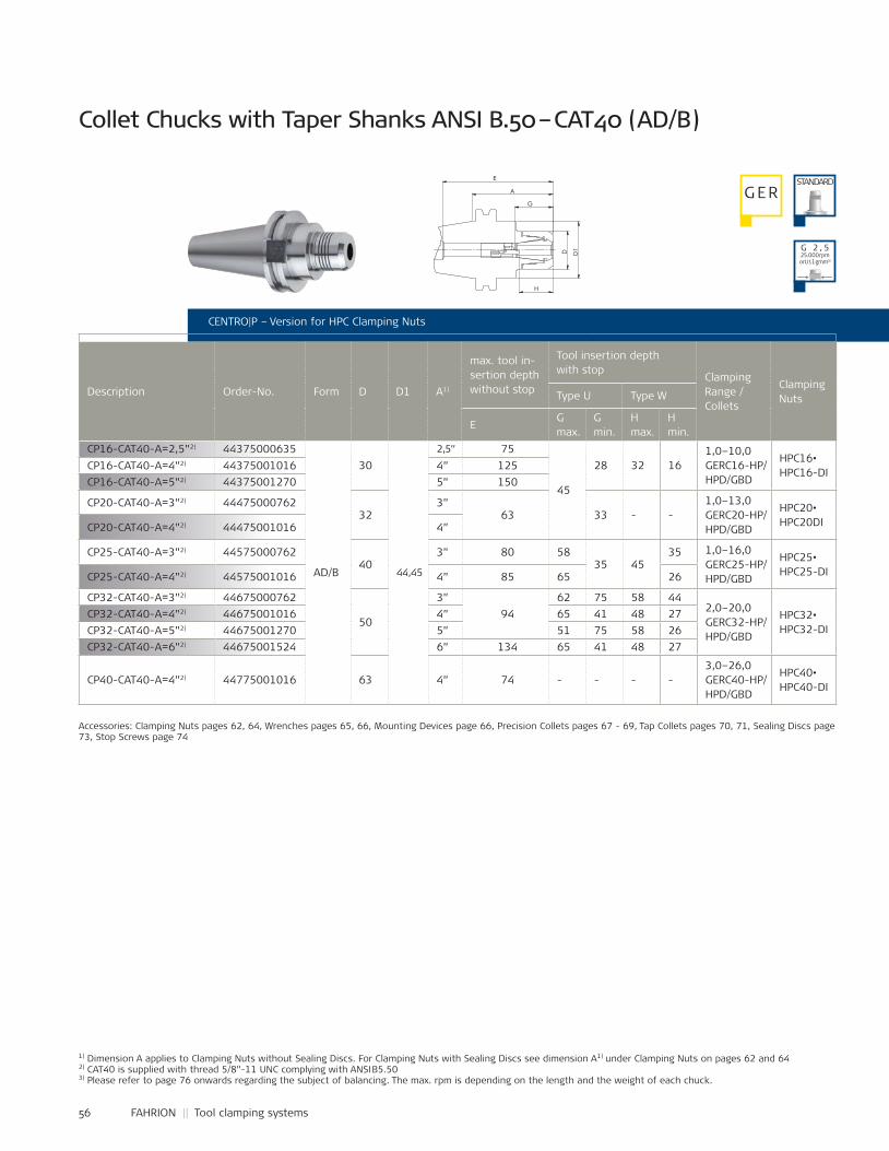
56 FAHRION || Tool clamping systems
CP16-CAT40-A=2,5”2) 44375000635
AD/B
30
44,45
2,5” 75
45
28 32 161,0–10,0GERC16-HP/HPD/GBD
HPC16•HPC16-DICP16-CAT40-A=4”2) 44375001016 4” 125
CP16-CAT40-A=5”2) 44375001270 5” 150
CP20-CAT40-A=3”2) 4447500076232
3”63 33 - -
1,0–13,0GERC20-HP/HPD/GBD
HPC20•HPC20DICP20-CAT40-A=4”2) 44475001016 4”
CP25-CAT40-A=3”2) 4457500076240
3” 80 5835 45
35 1,0–16,0GERC25-HP/HPD/GBD
HPC25•HPC25-DICP25-CAT40-A=4”2) 44575001016 4” 85 65 26
CP32-CAT40-A=3”2) 44675000762
50
3”94
62 75 58 442,0–20,0GERC32-HP/HPD/GBD
HPC32•HPC32-DI
CP32-CAT40-A=4”2) 44675001016 4” 65 41 48 27CP32-CAT40-A=5”2) 44675001270 5” 51 75 58 26CP32-CAT40-A=6”2) 44675001524 6” 134 65 41 48 27
CP40-CAT40-A=4”2) 44775001016 63 4” 74 - - - -3,0–26,0GERC40-HP/HPD/GBD
HPC40•HPC40-DI
CENTRO|P – Version for HPC Clamping Nuts
Collet Chucks with Taper Shanks ANSI B.50 – CAT40 (AD/B)
Description Order-No. Form D D1 A1)
max. tool in-sertion depth without stop
Tool insertion depth with stop
Clamping Range / Collets
ClampingNutsType U Type W
E G max.
G min.
H max.
H min.
Accessories: Clamping Nuts pages 62, 64, Wrenches pages 65, 66, Mounting Devices page 66, Precision Collets pages 67 - 69, Tap Collets pages 70, 71, Sealing Discs page 73, Stop Screws page 74
1) Dimension A applies to Clamping Nuts without Sealing Discs. For Clamping Nuts with Sealing Discs see dimension A1) under Clamping Nuts on pages 62 and 642) CAT40 is supplied with thread 5/8”-11 UNC complying with ANSI B5.503) Please refer to page 76 onwards regarding the subject of balancing. The max. rpm is depending on the length and the weight of each chuck.
G ERSTANDARD
G 2 , 525.000 rpmorU ≤ 1 gmm³)
D1
D
A
H
G
E
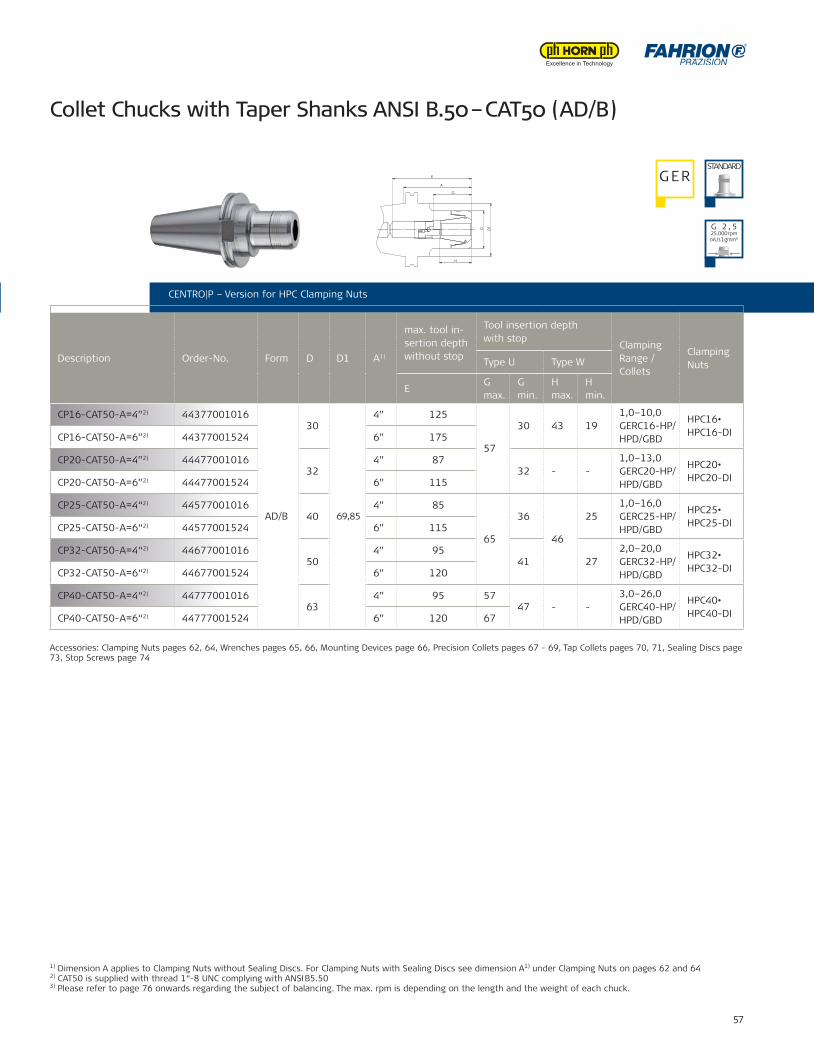
57
CP16-CAT50-A=4”2) 44377001016
AD/B
30
69,85
4” 125
57
30 43 191,0–10,0GERC16-HP/HPD/GBD
HPC16•HPC16-DICP16-CAT50-A=6”2) 44377001524 6” 175
CP20-CAT50-A=4”2) 4447700101632
4” 8732 - -
1,0–13,0GERC20-HP/HPD/GBD
HPC20•HPC20-DICP20-CAT50-A=6”2) 44477001524 6” 115
CP25-CAT50-A=4“2) 4457700101640
4” 85
65
36
46
251,0–16,0GERC25-HP/HPD/GBD
HPC25•HPC25-DICP25-CAT50-A=6“2) 44577001524 6” 115
CP32-CAT50-A=4“2) 4467700101650
4” 9541 27
2,0–20,0GERC32-HP/HPD/GBD
HPC32•HPC32-DICP32-CAT50-A=6“2) 44677001524 6” 120
CP40-CAT50-A=4“2) 4477700101663
4” 95 5747 - -
3,0–26,0GERC40-HP/HPD/GBD
HPC40•HPC40-DICP40-CAT50-A=6“2) 44777001524 6” 120 67
CENTRO|P – Version for HPC Clamping Nuts
Collet Chucks with Taper Shanks ANSI B.50 – CAT50 (AD/B)
CENTRO|P – Version for HPC Clamping Nuts
Description Order-No. Form D D1 A1)
max. tool in-sertion depth without stop
Tool insertion depth with stop
Clamping Range / Collets
ClampingNutsType U Type W
E G max.
G min.
H max.
H min.
Accessories: Clamping Nuts pages 62, 64, Wrenches pages 65, 66, Mounting Devices page 66, Precision Collets pages 67 - 69, Tap Collets pages 70, 71, Sealing Discs page 73, Stop Screws page 74
1) Dimension A applies to Clamping Nuts without Sealing Discs. For Clamping Nuts with Sealing Discs see dimension A1) under Clamping Nuts on pages 62 and 642) CAT50 is supplied with thread 1“-8 UNC complying with ANSI B5.503) Please refer to page 76 onwards regarding the subject of balancing. The max. rpm is depending on the length and the weight of each chuck.
G ERSTANDARD
G 2 , 525.000 rpmorU ≤ 1 gmm³)
D1
D
H
A
E
G
Name:±0,06
±0,1
±0,2
±0,3
±0,5
±1,0
44677000889Artikel-Nr.:
Artikel-Bez. 2:Gez.Gepr.Gen.
RohteilNr.
Kanten 0,3x45°gebrochen
Passmaß Abmaß
Maßstab:
1:1
-10
10-30
30-80
80-180
180-500
500-1000
zul.Abweichg.n.tol.bearb.Maße:
Werkstoff:
Datum:31.08.11 Ho
SpannzangenfutterCP32-CAT50-A=3,5"
verg. auf:Einsatztiefe:
Wärmebehandlung:
angelassen auf:
Gewicht: 1234 g
12.0
9.20
11 -
K:\S
W-A
WU
\Mod
elle
\CP-
Futt
er\Z
usam
men
stel
lung
en\C
P32\
CP-K
atal
og\4
4677
0008
89-K
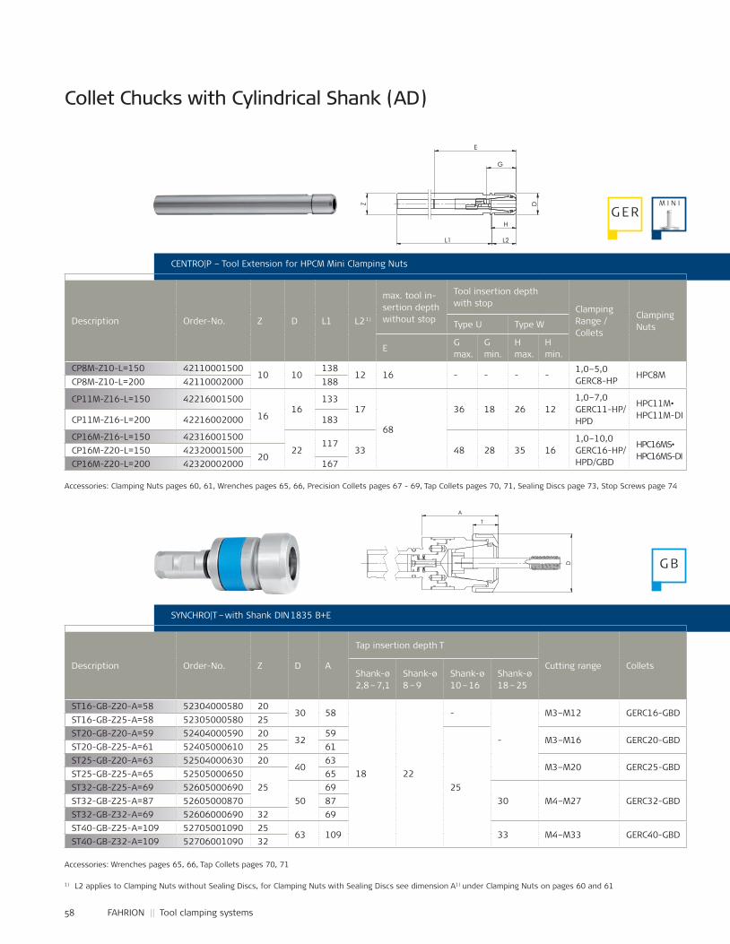
58 FAHRION || Tool clamping systems
CP8M-Z10-L=150 4211000150010 10
13812 16 - - - -
1,0–5,0GERC8-HP
HPC8MCP8M-Z10-L=200 42110002000 188
CP11M-Z16-L=150 42216001500
1616
13317
68
36 18 26 121,0–7,0GERC11-HP/HPD
HPC11M•HPC11M-DICP11M-Z16-L=200 42216002000 183
CP16M-Z16-L=150 4231600150022
11733 48 28 35 16
1,0–10,0GERC16-HP/HPD/GBD
HPC16MS•HPC16MS-DI
CP16M-Z20-L=150 4232000150020
CP16M-Z20-L=200 42320002000 167
ST16-GB-Z20-A=58 52304000580 2030 58
18 22
-
-
M3–M12 GERC16-GBDST16-GB-Z25-A=58 52305000580 25ST20-GB-Z20-A=59 52404000590 20
3259
25
M3–M16 GERC20-GBDST20-GB-Z25-A=61 52405000610 25 61ST25-GB-Z20-A=63 52504000630 20
4063
M3–M20 GERC25-GBDST25-GB-Z25-A=65 52505000650
2565
ST32-GB-Z25-A=69 5260500069050
6930 M4–M27 GERC32-GBDST32-GB-Z25-A=87 52605000870 87
ST32-GB-Z32-A=69 52606000690 32 69ST40-GB-Z25-A=109 52705001090 25
63 109 33 M4–M33 GERC40-GBDST40-GB-Z32-A=109 52706001090 32
CENTRO|P – Tool Extension for HPCM Mini Clamping Nuts
Description Order-No. Z D L1 L2 1)
max. tool in-sertion depth without stop
Tool insertion depth with stop
Clamping Range / Collets
ClampingNutsType U Type W
E G max.
G min.
H max.
H min.
1) L2 applies to Clamping Nuts without Sealing Discs, for Clamping Nuts with Sealing Discs see dimension A1) under Clamping Nuts on pages 60 and 61
SYNCHRO|T – with Shank DIN 1835 B+E
Description Order-No. Z D A
Tap insertion depth T
Cutting range ColletsShank-ø2,8 – 7,1
Shank-ø8 – 9
Shank-ø10 – 16
Shank-ø18 – 25
Accessories: Clamping Nuts pages 60, 61, Wrenches pages 65, 66, Precision Collets pages 67 - 69, Tap Collets pages 70, 71, Sealing Discs page 73, Stop Screws page 74
Accessories: Wrenches pages 65, 66, Tap Collets pages 70, 71
Collet Chucks with Cylindrical Shank (AD)
M I N IG ER
G B
Z
L2
H
D
G
L1
E
A
T
D
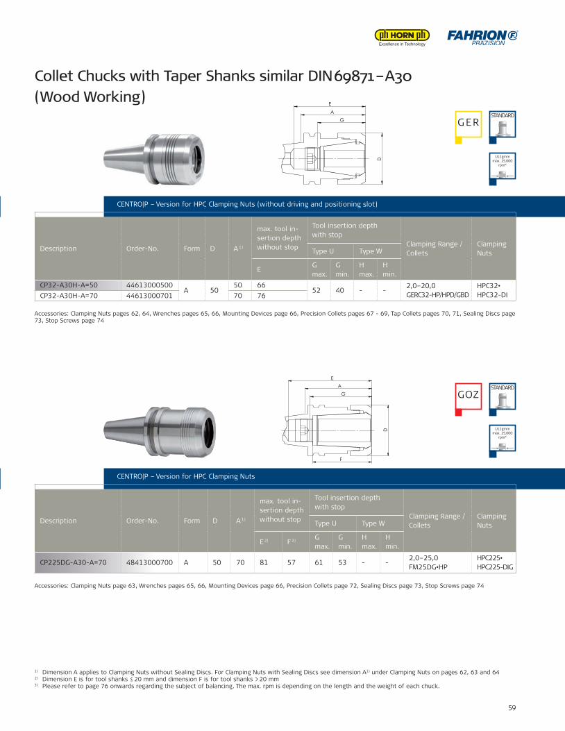
59
CP32-A30H-A=50 44613000500A 50
50 6652 40 - -
2,0–20,0GERC32-HP/HPD/GBD
HPC32•HPC32-DICP32-A30H-A=70 44613000701 70 76
CP225DG-A30-A=70 48413000700 A 50 70 81 57 61 53 - -2,0–25,0FM25DG•HP
HPC225•HPC225-DIG
1) Dimension A applies to Clamping Nuts without Sealing Discs. For Clamping Nuts with Sealing Discs see dimension A1) under Clamping Nuts on pages 62, 63 and 642) Dimension E is for tool shanks ≤ 20 mm and dimension F is for tool shanks > 20 mm3) Please refer to page 76 onwards regarding the subject of balancing. The max. rpm is depending on the length and the weight of each chuck.
CENTRO|P – Tool Extension for HPCM Mini Clamping Nuts
SYNCHRO|T – with Shank DIN 1835 B+E CENTRO|P – Version for HPC Clamping Nuts
Description Order-No. Form D A 1)
max. tool in-sertion depth without stop
Tool insertion depth with stop
Clamping Range / Collets
ClampingNutsType U Type W
E 2) F 2) G max.
G min.
H max.
H min.
CENTRO|P – Version for HPC Clamping Nuts (without driving and positioning slot)
Description Order-No. Form D A 1)
max. tool in-sertion depth without stop
Tool insertion depth with stop
Clamping Range / Collets
ClampingNutsType U Type W
EG max.
G min.
H max.
H min.
Accessories: Clamping Nuts page 63, Wrenches pages 65, 66, Mounting Devices page 66, Precision Collets page 72, Sealing Discs page 73, Stop Screws page 74
Accessories: Clamping Nuts pages 62, 64, Wrenches pages 65, 66, Mounting Devices page 66, Precision Collets pages 67 - 69, Tap Collets pages 70, 71, Sealing Discs page 73, Stop Screws page 74
Collet Chucks with Taper Shanks similar DIN 69871 – A30 (Wood Working)
G ERSTANDARD
GOZSTANDARD
U≤1gmm max. 25.000
rpm³)
U≤1gmm max. 25.000
rpm³)
A
E
D
G
DA
E
G
F
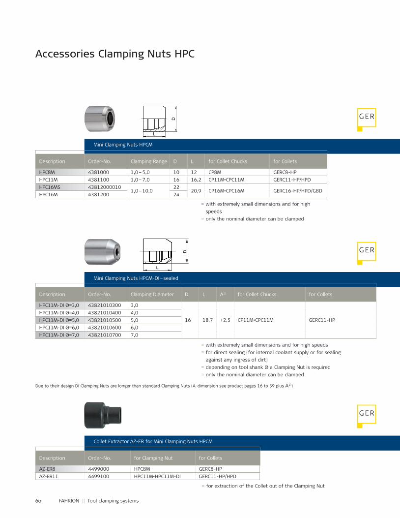
60 FAHRION || Tool clamping systems
HPC8M 4381000 1,0 – 5,0 10 12 CP8M GERC8-HPHPC11M 4381100 1,0 – 7,0 16 16,2 CP11M•CPC11M GERC11-HP/HPDHPC16MS 43812000010
1,0 – 10,022
20,9 CP16M•CPC16M GERC16-HP/HPD/GBDHPC16M 4381200 24
HPC11M-DI Ø=3,0 43821010300 3,0
16 18,7 +2,5 CP11M•CPC11M GERC11-HPHPC11M-DI Ø=4,0 43821010400 4,0HPC11M-DI Ø=5,0 43821010500 5,0HPC11M-DI Ø=6,0 43821010600 6,0HPC11M-DI Ø=7,0 43821010700 7,0
AZ-ER8 4499000 HPC8M GERC8-HPAZ-ER11 4499100 HPC11M•HPC11M-DI GERC11-HP/HPD
Accessories Clamping Nuts HPC
Mini Clamping Nuts HPCM
Mini Clamping Nuts HPCM-DI – sealed
Collet Extractor AZ-ER for Mini Clamping Nuts HPCM
Description Order-No. Clamping Range D L for Collet Chucks for Collets
Description Order-No. Clamping Diameter D L A1) for Collet Chucks for Collets
Description Order-No. for Clamping Nut for Collets
= with extremely small dimensions and for high speeds
= only the nominal diameter can be clamped
= for extraction of the Collet out of the Clamping Nut
Due to their design DI Clamping Nuts are longer than standard Clamping Nuts (A-dimension see product pages 16 to 59 plus A1))
= with extremely small dimensions and for high speeds= for direct sealing (for internal coolant supply or for sealing
against any ingress of dirt)= depending on tool shank Ø a Clamping Nut is required= only the nominal diameter can be clamped
G ER
G ER
G ER
D
L
L
D
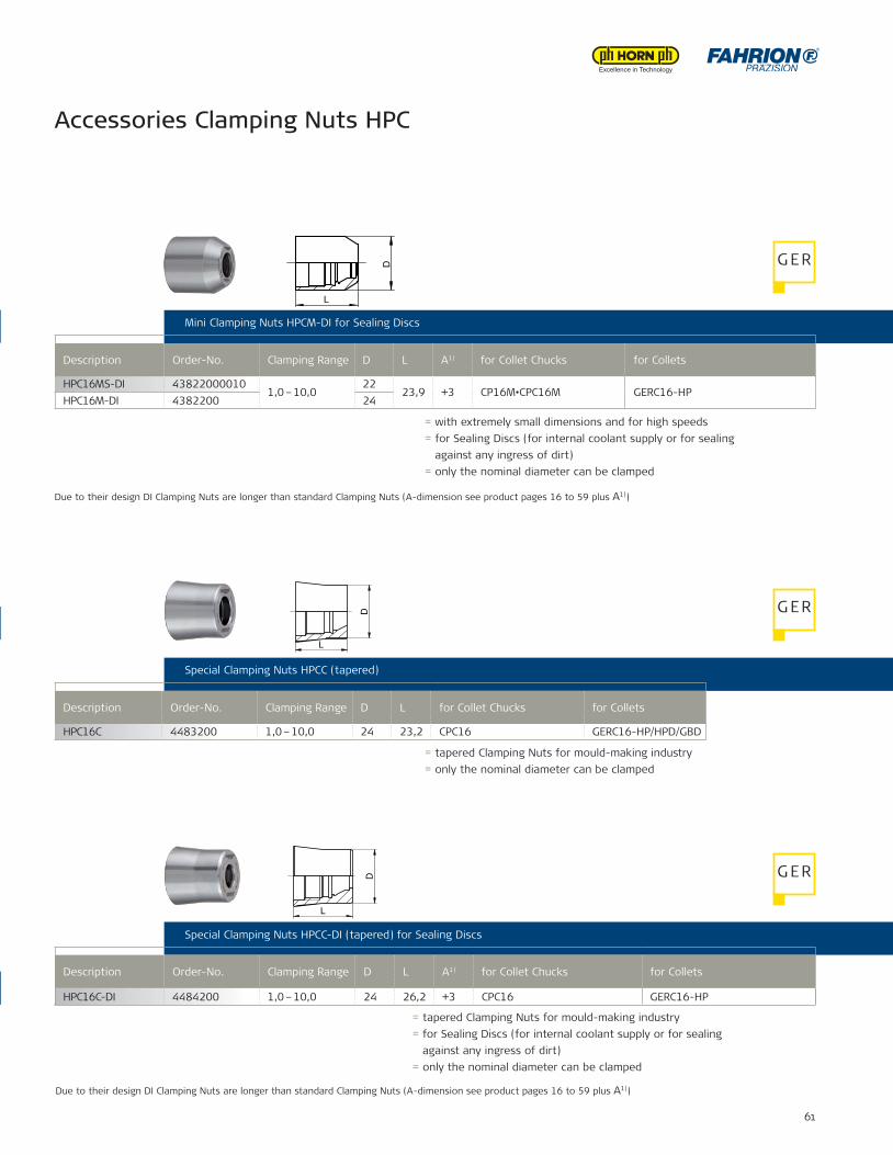
61
HPC16C 4483200 1,0 – 10,0 24 23,2 CPC16 GERC16-HP/HPD/GBD
HPC16C-DI 4484200 1,0 – 10,0 24 26,2 +3 CPC16 GER16-HP/HPD/GBD
HPC16MS-DI 438220000101,0 – 10,0
2223,9 +3 CP16M•CPC16M GERC16-HP
HPC16M-DI 4382200 24
HPC16C-DI 4484200 1,0 – 10,0 24 26,2 +3 CPC16 GERC16-HP
Accessories Clamping Nuts HPC
Mini Clamping Nuts HPCM
Mini Clamping Nuts HPCM-DI – sealed
Collet Extractor AZ-ER for Mini Clamping Nuts HPCM
Mini Clamping Nuts HPCM-DI for Sealing Discs
Description Order-No. Clamping Range D L A1) for Collet Chucks for Collets
= with extremely small dimensions and for high speeds= for Sealing Discs (for internal coolant supply or for sealing
against any ingress of dirt)= only the nominal diameter can be clamped
Due to their design DI Clamping Nuts are longer than standard Clamping Nuts (A-dimension see product pages 16 to 59 plus A1))
Special Clamping Nuts HPCC (tapered)
Description Order-No. Clamping Range D L for Collet Chucks for Collets
= tapered Clamping Nuts for mould-making industry= only the nominal diameter can be clamped
Special Clamping Nuts HPCC-DI (tapered) for Sealing Discs
Description Order-No. Clamping Range D L A1) for Collet Chucks for Collets
= tapered Clamping Nuts for mould-making industry= for Sealing Discs (for internal coolant supply or for sealing
against any ingress of dirt) = only the nominal diameter can be clamped
Due to their design DI Clamping Nuts are longer than standard Clamping Nuts (A-dimension see product pages 16 to 59 plus A1))
G ER
G ER
G ER
L
D
D
L L
D
L
D
D
L
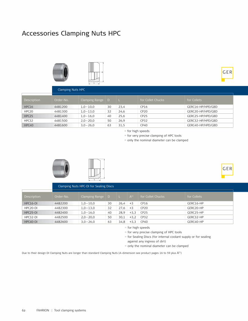
62 FAHRION || Tool clamping systems
HPC16 4481200 1,0 – 10,0 30 23,4 CP16 GERC16-HP/HPD/GBDHPC20 4481300 1,0 – 13,0 32 24,6 CP20 GERC20-HP/HPD/GBDHPC25 4481400 1,0 – 16,0 40 25,6 CP25 GERC25-HP/HPD/GBDHPC32 4481500 2,0 – 20,0 50 26,9 CP32 GERC32-HP/HPD/GBDHPC40 4481600 3,0 – 26,0 63 31,5 CP40 GERC40-HP/HPD/GBD
HPC16-DI 4482200 1,0 – 10,0 30 26,4 +3 CP16 GERC16-HPHPC20-DI 4482300 1,0 – 13,0 32 27,6 +3 CP20 GERC20-HPHPC25-DI 4482400 1,0 – 16,0 40 28,9 +3,3 CP25 GERC25-HPHPC32-DI 4482500 2,0 – 20,0 50 30,1 +3,2 CP32 GERC32-HPHPC40-DI 4482600 3,0 – 26,0 63 34,8 +3,3 CP40 GERC40-HP
Accessories Clamping Nuts HPC
Clamping Nuts HPC
Description Order-No. Clamping Range D L for Collet Chucks for Collets
= for high speeds = for very precise clamping of HPC tools= only the nominal diameter can be clamped
Clamping Nuts HPC-DI for Sealing Discs
Description Order-No. Clamping Range D L A1) for Collet Chucks for Collets
= for high speeds= for very precise clamping of HPC tools= for Sealing Discs (for internal coolant supply or for sealing
against any ingress of dirt)= only the nominal diameter can be clamped
Due to their design DI Clamping Nuts are longer than standard Clamping Nuts (A-dimension see product pages 16 to 59 plus A1))
G ER
G ER
L
D
L
D
D
L L
D
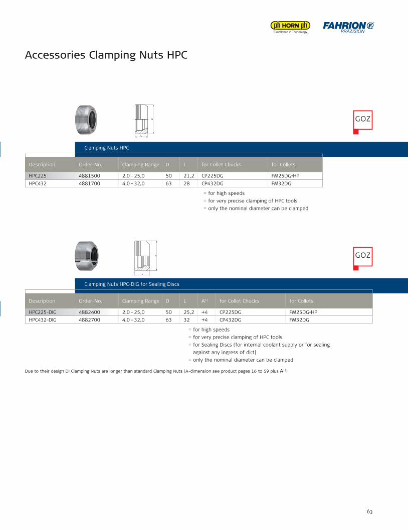
63
HPC225 4881500 2,0 – 25,0 50 21,2 CP225DG FM25DG•HPHPC432 4881700 4,0 – 32,0 63 28 CP432DG FM32DG
HPC225-DIG 4882400 2,0 – 25,0 50 25,2 +4 CP225DG FM25DG•HPHPC432-DIG 4882700 4,0 – 32,0 63 32 +4 CP432DG FM32DG
Accessories Clamping Nuts HPC
Clamping Nuts HPC
Clamping Nuts HPC-DI for Sealing Discs
= for high speeds= for very precise clamping of HPC tools= for Sealing Discs (for internal coolant supply or for sealing
against any ingress of dirt)= only the nominal diameter can be clamped
Clamping Nuts HPC
Description Order-No. Clamping Range D L for Collet Chucks for Collets
= for high speeds = for very precise clamping of HPC tools= only the nominal diameter can be clamped
Clamping Nuts HPC-DIG for Sealing Discs
Description Order-No. Clamping Range D L A1) for Collet Chucks for Collets
Due to their design DI Clamping Nuts are longer than standard Clamping Nuts (A-dimension see product pages 16 to 59 plus A1))
= for high speeds = for very precise clamping of HPC tools= for Sealing Discs (for internal coolant supply or for sealing
against any ingress of dirt)= only the nominal diameter can be clamped
GOZ
GOZ
D
L
D
L
D
L
D
L
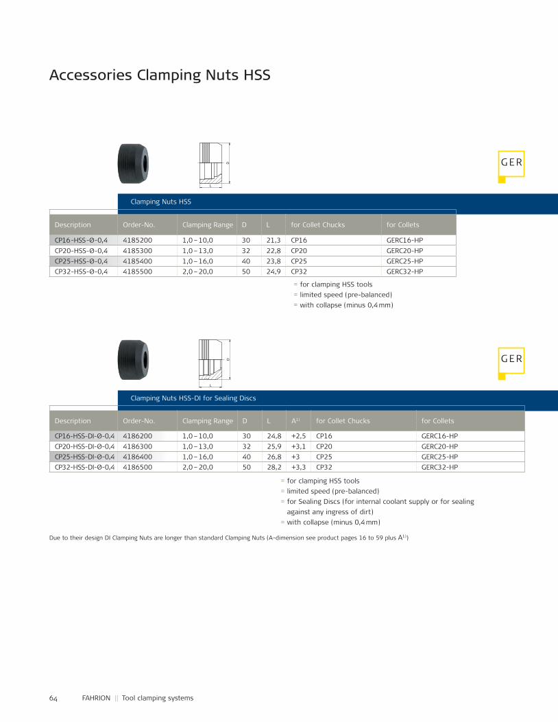
64 FAHRION || Tool clamping systems
CP16 -HSS -Ø -0,4 4185200 1,0 – 10,0 30 21,3 CP16 GERC16-HPCP20-HSS-Ø-0,4 4185300 1,0 – 13,0 32 22,8 CP20 GERC20-HPCP25-HSS-Ø-0,4 4185400 1,0 – 16,0 40 23,8 CP25 GERC25-HPCP32-HSS-Ø-0,4 4185500 2,0 – 20,0 50 24,9 CP32 GERC32-HP
CP16-HSS-DI-Ø-0,4 4186200 1,0 – 10,0 30 24,8 +2,5 CP16 GERC16-HPCP20-HSS-DI-Ø-0,4 4186300 1,0 – 13,0 32 25,9 +3,1 CP20 GERC20-HPCP25-HSS-DI-Ø-0,4 4186400 1,0 – 16,0 40 26,8 +3 CP25 GERC25-HPCP32-HSS-DI-Ø-0,4 4186500 2,0 – 20,0 50 28,2 +3,3 CP32 GERC32-HP
Accessories Clamping Nuts HSS
Clamping Nuts HSS
Description Order-No. Clamping Range D L for Collet Chucks for Collets
= for clamping HSS tools = limited speed (pre-balanced)= with collapse (minus 0,4 mm)
Clamping Nuts HSS-DI for Sealing Discs
Description Order-No. Clamping Range D L A1) for Collet Chucks for Collets
= for clamping HSS tools= limited speed (pre-balanced)= for Sealing Discs (for internal coolant supply or for sealing
against any ingress of dirt)= with collapse (minus 0,4 mm)
Due to their design DI Clamping Nuts are longer than standard Clamping Nuts (A-dimension see product pages 16 to 59 plus A1))
G ER
G ER
L
D
L
D
D
L
D
L
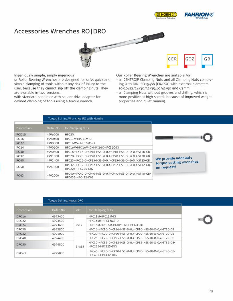
65
ROD10 4996200 HPC8MRO16 4990400 HPC11M•HPC11M-DIRO22 4990500 HPC16MS•HPC16MS-DIRO24 4990600 HPC16M•HPC16M-DI•HPC16C•HPC16C-DIRO30 4990800 HPC16•HPC16-DI•CP16-HSS-Ø-0,4•CP16-HSS-DI-Ø-0,4•ST16-GBRO32 4991000 HPC20•HPC20-DI•CP20-HSS-Ø-0,4•CP20-HSS-DI-Ø-0,4•ST20-GBRO40 4991400 HPC25•HPC25-DI•CP25-HSS-Ø-0,4•CP25-HSS-DI-Ø-0,4•ST25-GB
RO50 4991800HPC32•HPC32-DI•CP32-HSS-Ø-0,4•CP32-HSS-DI-Ø-0,4•ST32-GB•HPC225•HPC225-DIG
RO63 4992000HPC40•HPC40-DI•CP40-HSS-Ø-0,4•CP40-HSS-DI-Ø-0,4•ST40-GB•HPC432•HPC432-DIG
DRO16 4993400
9x12
HPC11M•HPC11M-DIDRO22 4993500 HPC16MS•HPC16MS-DIDRO24 4993600 HPC16M•HPC16M-DI•HPC16C•HPC16C-DIDRO30 4993800 HPC16•HPC16-DI•CP16-HSS-Ø-0,4•CP16-HSS-DI-Ø-0,4•ST16-GBDRO32 4994000 HPC20•HPC20-DI•CP20-HSS-Ø-0,4•CP20-HSS-DI-Ø-0,4•ST20-GBDRO40 4994400
14x18
HPC25•HPC25-DI•CP25-HSS-Ø-0,4•CP25-HSS-DI-Ø-0,4•ST25-GB
DRO50 4994800HPC32•HPC32-DI•CP32-HSS-Ø-0,4•CP32-HSS-DI-Ø-0,4•ST32-GB•HPC225•HPC225-DIG
DRO63 4995000HPC40•HPC40-DI•CP40-HSS-Ø-0,4•CP40-HSS-DI-Ø-0,4•ST40-GB•HPC432•HPC432-DIG
Clamping Nuts HSS
Clamping Nuts HSS-DI for Sealing Discs
Torque Setting Wrenches RO with Handle
Torque Setting Heads DRO
Ingeniously simple, simply ingenious!ur Roller Bearing Wrenches are designed for safe, quick and simple clamping of tools without any risk of injury to the user, because they cannot slip off the clamping nuts. They are available in two versions: with standard handle or with square drive adapter for de£ ned clamping of tools using a torque wrench.
Description Order-No. for Clamping Nuts
Description Order-No. VKT for Clamping Nuts
Our Roller Bearing Wrenches are suitable for:= all CENTRO|P Clamping Nuts and all Clamping Nuts comply-
ing with DIN ISO 15488 (ER/ESX) with external diameters 10 /16 /22 /24 /30 /32 /35 /40 /42 /50 and 63 mm
= all Clamping Nuts without grooves and drilling, which is more positive at high speeds because of improved weight properties and quiet running.
Accessories Wrenches RO | DRO
G ER GOZ G B
We provide adequate
torque setting wrenches
on request!

66 FAHRION || Tool clamping systems
TBRS25 4980200 25 HSK25 TBRS32 4980400 32 HSK32•C3TBRS40 4980600 40 HSK40•C4TBRS46 4980800 46 MAS/BT30TBRS50 4981000 50 SK30•HSK50•C5TBRS63 4981200 63 SK40•HSK63•C6•MAS/BT40•CAT40TBRS80 4981600 80 HSK80•C8TBRS97 4981800 97,5 SK50TBRS100 4982000 100 HSK100•MAS/BT50•CAT50
Accessories Wrenches DRMO
Accessories Mounting Devices TBRS
Torque Setting Wrenches DRMO
Description Order-No. VKT Torque range for Roller Bearing Head
Mounting Devices TBRS with Roller Bearing
Description Order-No. D for holder shanks
= for easy and safe clamping of holder shanks at the ¸ange using rollers for mounting and removing cutting tools, therefore self clamping and ideal for HSK forms E and F as well as polygonal shanks
= for all common holder shanks such as SK (DIN 69871), HSK (DIN 69893 forms A, B, C, D, E, F), polygonal shanks (ISO 26623-1), MAS/BT (JIS B 6339) and CAT (ANSI B5.50)
G ER GOZ G B
G ER GOZ G B
DRMO-10-50 4900200 9x12 10 - 50 Nm DRO16•DRO22•DRO24DRMO-20-100 4900400 9x12 20 - 100 Nm DRO24•DRO30•DRO32DRMO-40-200 4900600 14x18 40 - 200 Nm DRO40•DRO50•DRO63DRMO-60-300 4900800 14x18 60 - 300 Nm DRO63 (for CP432DG)
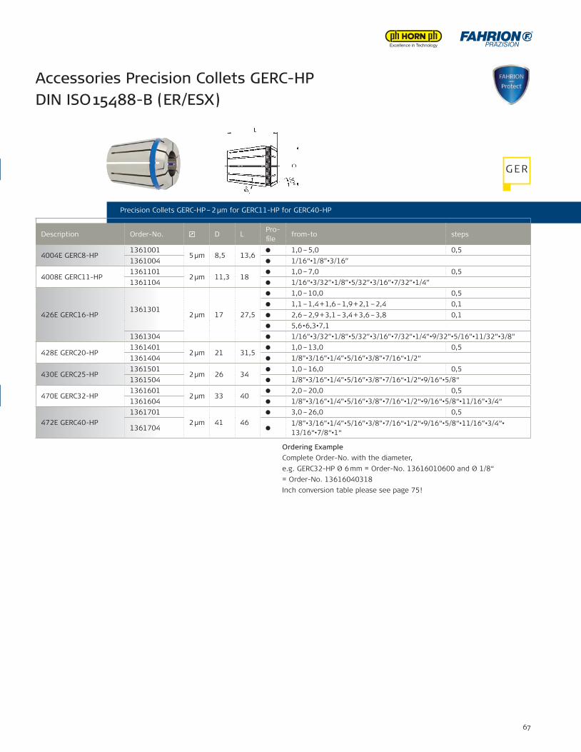
67
Description Order-No. D LPro-£ le
from-to steps
4004E GERC8-HP1361001
5 μm 8,5 13,61,0 – 5,0 0,5
1361004 1/16“•1/8”•3/16”
4008E GERC11-HP1361101
2 μm 11,3 181,0 – 7,0 0,5
1361104 1/16“•3/32”•1/8”•5/32”•3/16”•7/32”•1/4”
426E GERC16-HP1361301
2 μm 17 27,5
1,0 – 10,0 0,51,1 – 1,4 + 1,6 – 1,9 + 2,1 – 2,4 0,12,6 – 2,9 + 3,1 – 3,4 + 3,6 – 3,8 0,15,6•6,3•7,1
1361304 1/16”•3/32”•1/8”•5/32”•3/16”•7/32”•1/4”•9/32”•5/16”•11/32”•3/8”
428E GERC20-HP1361401
2 μm 21 31,51,0 – 13,0 0,5
1361404 1/8”•3/16”•1/4”•5/16”•3/8”•7/16“•1/2“
430E GERC25-HP1361501
2 μm 26 341,0 – 16,0 0,5
1361504 1/8”•3/16”•1/4”•5/16”•3/8”•7/16“•1/2“•9/16“•5/8“
470E GERC32-HP1361601
2 μm 33 402,0 – 20,0 0,5
1361604 1/8”•3/16”•1/4”•5/16”•3/8”•7/16“•1/2“•9/16“•5/8“•11/16”•3/4“
472E GERC40-HP1361701
2 μm 41 463,0 – 26,0 0,5
13617041/8”•3/16”•1/4”•5/16”•3/8”•7/16“•1/2“•9/16“•5/8“•11/16”•3/4“•13/16“•7/8“•1“
Accessories Precision Collets GERC-HP DIN ISO 15488-B (ER/ESX)
Precision Collets GERC-HP – 2 μm for GERC11-HP for GERC40-HP
Description Order-No. D LPro-£ le
from-to steps
Ordering ExampleComplete Order-No. with the diameter,e.g. GERC32-HP Ø 6 mm = Order-No. 13616010600 and Ø 1/8“ = Order-No. 13616040318Inch conversion table please see page 75!
G ERTorque Setting Wrenches DRMO
Mounting Devices TBRS with Roller Bearing
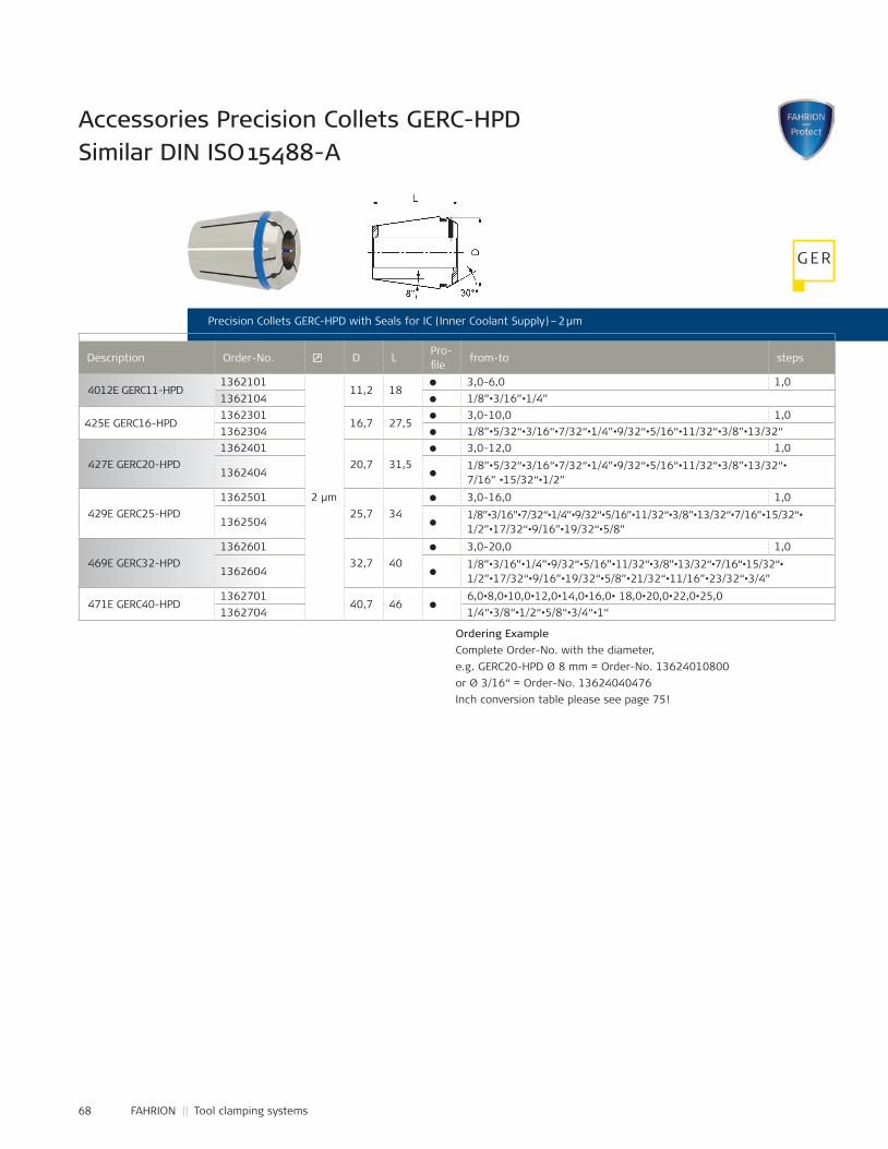
68 FAHRION || Tool clamping systems
4012E GERC11-HPD1362101
2 μm
11,2 18 3,0-6,0 1,0
1362104 1/8”•3/16”•1/4”
425E GERC16-HPD1362301
16,7 27,5 3,0-10,0 1,0
1362304 1/8”•5/32“•3/16“•7/32“•1/4”•9/32“•5/16“•11/32“•3/8”•13/32“
427E GERC20-HPD1362401
20,7 31,5 3,0-12,0 1,0
1362404 1/8”•5/32“•3/16“•7/32“•1/4”•9/32“•5/16“•11/32“•3/8”•13/32“•7/16” •15/32“•1/2”
429E GERC25-HPD1362501
25,7 34 3,0-16,0 1,0
1362504 1/8”•3/16”•7/32“•1/4”•9/32“•5/16”•11/32“•3/8”•13/32“•7/16”•15/32“•1/2”•17/32“•9/16”•19/32“•5/8”
469E GERC32-HPD1362601
32,7 40 3,0-20,0 1,0
1362604 1/8”•3/16”•1/4”•9/32“•5/16”•11/32“•3/8”•13/32“•7/16“•15/32“•1/2”•17/32“•9/16”•19/32“•5/8”•21/32“•11/16”•23/32“•3/4”
471E GERC40-HPD1362701
40,7 46 6,0•8,0•10,0•12,0•14,0•16,0• 18,0•20,0•22,0•25,0
1362704 1/4“•3/8“•1/2“•5/8“•3/4“•1“
Accessories Precision Collets GERC-HPD Similar DIN ISO 15488-A
Precision Collets GERC-HPD with Seals for IC (Inner Coolant Supply) – 2 μm
Description Order-No. D LPro-£ le
from-to steps
Ordering ExampleComplete Order-No. with the diameter, e.g. GERC20-HPD Ø 8 mm = Order-No. 13624010800 or Ø 3/16“ = Order-No. 13624040476Inch conversion table please see page 75!
G ER
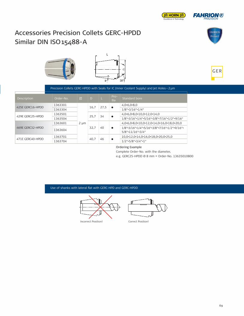
69
425E GERC16-HPDD1363301
2 μm
16,7 27,5 4,0•6,0•8,0
1363304 1/8“•3/16“•1/4“
429E GERC25-HPDD1363501
25,7 34 4,0•6,0•8,0•10,0•12,0•14,0
1363504 1/8“•3/16“•1/4“•5/16“•3/8“•7/16“•1/2“•9/16“
469E GERC32-HPDD1363601
32,7 40 4,0•6,0•8,0•10,0•12,0•14,0•16,0•18,0•20,0
13636041/8“•3/16“•1/4“•5/16“•3/8“•7/16“•1/2“•9/16“•5/8“•11/16“•3/4“
471E GERC40-HPDD1363701
40,7 46 10,0•12,0•14,0•16,0•18,0•20,0•25,0
1363704 1/2“•5/8“•3/4“•1“
Accessories Precision Collets GERC-HPD Similar DIN ISO 15488-A
Accessories Precision Collets GERC-HPDD Similar DIN ISO 15488-A
Ordering ExampleComplete Order-No. with the diameter,e.g. GERC25-HPDD Ø 8 mm = Order-No. 13635010800
Precision Collets GERC-HPD with Seals for IC (Inner Coolant Supply) – 2 μm Precision Collets GERC-HPDD with Seals for IC (Inner Coolant Supply) and Jet Holes – 2 μm
Use of shanks with lateral ̧at with GERC-HPD and GERC-HPDD
Description Order-No. D LPro-£ le
Standard bore
Incorrect Position! Correct Position!
Ordering ExampleComplete Order-No. with the diameter, e.g. GERC20-HPD Ø 8 mm = Order-No. 13624010800 or Ø 3/16“ = Order-No. 13624040476Inch conversion table please see page 75!
G ER
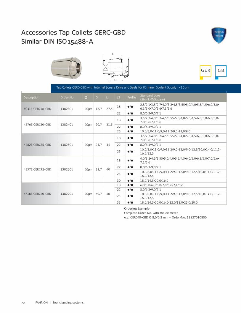
70 FAHRION || Tool clamping systems
Accessories Tap Collets GERC-GBD Similar DIN ISO 15488-A
Tap Collets GERC-GBD with Internal Square Drive and Seals for IC (Inner Coolant Supply) – 10 μm
Description Order-No. D L L2 Pro£ leStandard bore(Shank-Ø/Square)
Ordering ExampleComplete Order-No. with the diameter,e.g. GERC40-GBD Ø 8,0/6,3 mm = Order-No. 13827010800
4031E GERC16-GBD 1382301 10 μm 16,7 27,518 /
2,8/2,1•3,5/2,7•4,0/3,2•4,5/3,55•5,0/4,0•5,5/4,5•6,0/5,0•6,3/5,0•7,0/5,6•7,1/5,6
22 / 8,0/6,3•9,0/7,1
4276E GERC20-GBD 1382401 10 μm 20,7 31,518 /
3,5/2,7•4,0/3,2•4,5/3,55•5,0/4,0•5,5/4,5•6,0/5,0•6,3/5,0•7,0/5,6•7,1/5,6
22 / 8,0/6,3•9,0/7,125 / 10,0/8,0•11,0/9,0•11,2/9,0•12,0/9,0
4282E GERC25-GBD 1382501 10 μm 25,7 34
18 / 3,5/2,7•4,0/3,2•4,5/3,55•5,0/4,0•5,5/4,5•6,0/5,0•6,3/5,0•7,0/5,6•7,1/5,6
22 / 8,0/6,3•9,0/7,1
25 / 10,0/8,0•11,0/9,0•11,2/9,0•12,0/9,0•12,5/10,0•14,0/11,2•16,0/12,5
4537E GERC32-GBD 1382601 10 μm 32,7 40
18 / 4,0/3,2•4,5/3,55•5,0/4,0•5,5/4,5•6,0/5,0•6,3/5,0•7,0/5,6•7,1/5,6
22 / 8,0/6,3•9,0/7,1
25 / 10,0/8,0•11,0/9,0•11,2/9,0•12,0/9,0•12,5/10,0•14,0/11,2•16,0/12,5
30 / 18,0/14,5•20,0/16,0
4716E GERC40-GBD 1382701 10 μm 40,7 46
18 / 6,0/5,0•6,3/5,0•7,0/5,6•7,1/5,622 / ww 8,0/6,3•9,0/7,1
25 / ww
10,0/8,0•11,0/9,0•11,2/9,0•12,0/9,0•12,5/10,0•14,0/11,2•16,0/12,5
33 / ww 18,0/14,5•20,0/16,0•22,0/18,0•25,0/20,0
G ER G B
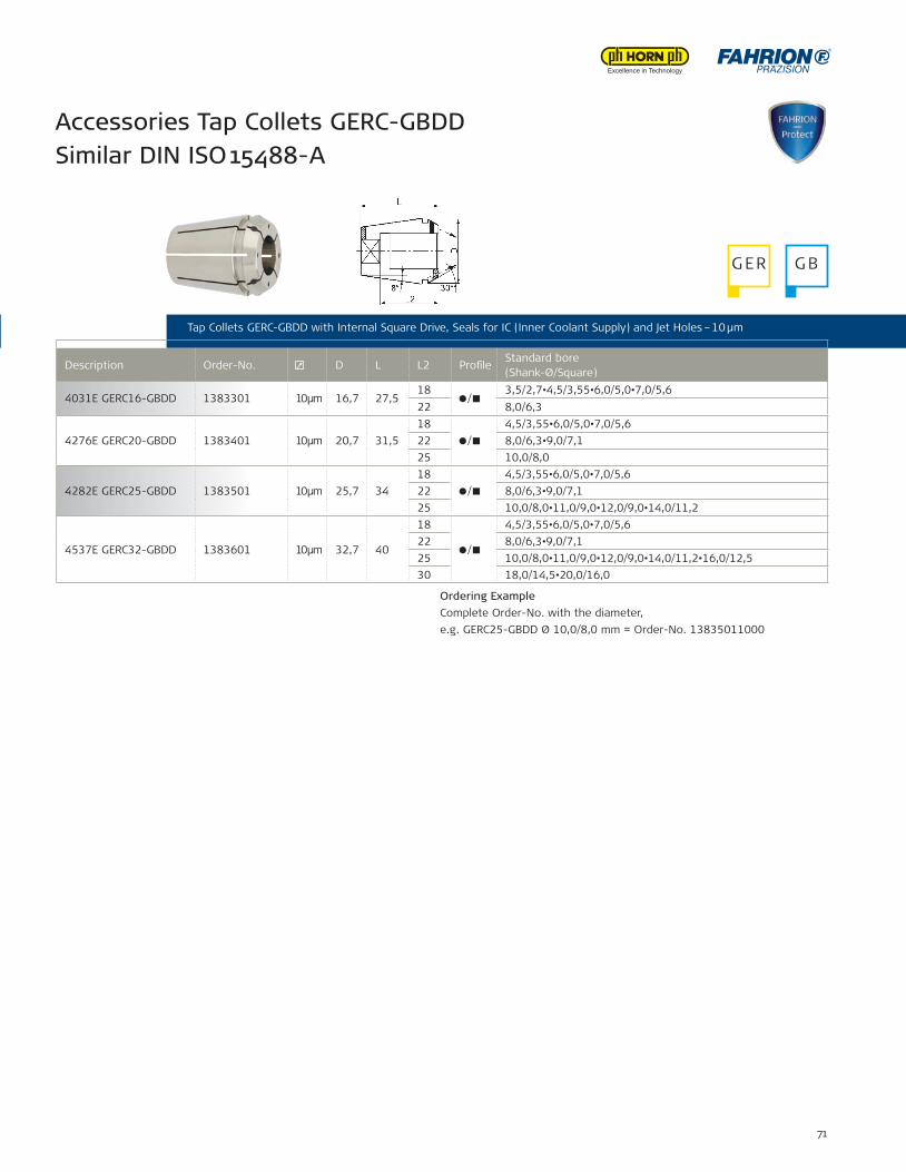
71
Tap Collets GERC-GBD with Internal Square Drive and Seals for IC (Inner Coolant Supply) – 10 μm
Accessories Tap Collets GERC-GBDD Similar DIN ISO 15488-A
Tap Collets GERC-GBDD with Internal Square Drive, Seals for IC (Inner Coolant Supply) and Jet Holes – 10 μm
Description Order-No. D L L2 Pro£ leStandard bore(Shank-Ø/Square)
4031E GERC16-GBDD 1383301 10 μm 16,7 27,518
/ ww
3,5/2,7•4,5/3,55•6,0/5,0•7,0/5,622 8,0/6,3
4276E GERC20-GBDD 1383401 10 μm 20,7 31,518
/ ww
4,5/3,55•6,0/5,0•7,0/5,622 8,0/6,3•9,0/7,125 10,0/8,0
4282E GERC25-GBDD 1383501 10 μm 25,7 3418
/ ww
4,5/3,55•6,0/5,0•7,0/5,622 8,0/6,3•9,0/7,125 10,0/8,0•11,0/9,0•12,0/9,0•14,0/11,2
4537E GERC32-GBDD 1383601 10 μm 32,7 40
18
/ ww
4,5/3,55•6,0/5,0•7,0/5,622 8,0/6,3•9,0/7,125 10,0/8,0•11,0/9,0•12,0/9,0•14,0/11,2•16,0/12,530 18,0/14,5•20,0/16,0
Ordering ExampleComplete Order-No. with the diameter, e.g. GERC25-GBDD Ø 10,0/8,0 mm = Order-No. 13835011000
G ER G B
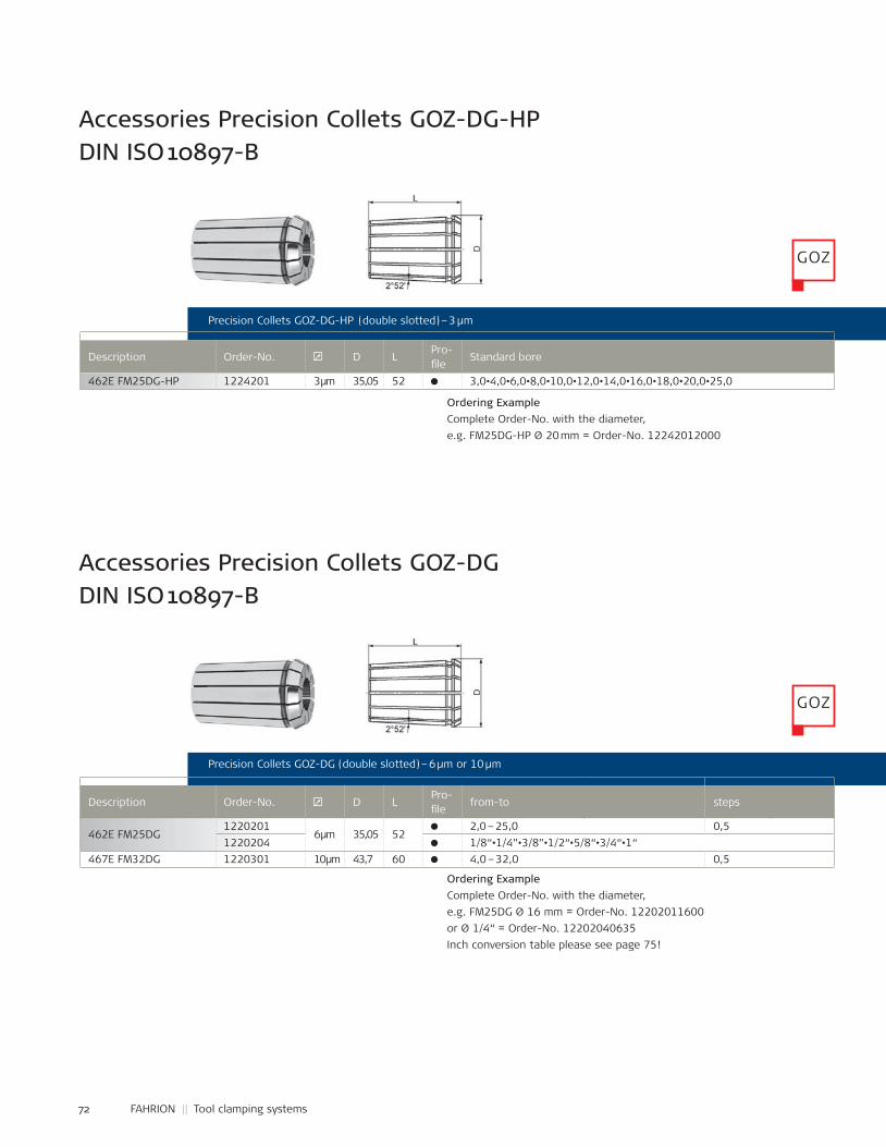
72 FAHRION || Tool clamping systems
462E FM25DG-HP 1224201 3 μm 35,05 52 3,0•4,0•6,0•8,0•10,0•12,0•14,0•16,0•18,0•20,0•25,0
462E FM25DG1220201
6 μm 35,05 522,0 – 25,0 0,5
1220204 1/8“•1/4”•3/8”•1/2“•5/8“•3/4“•1“467E FM32DG 1220301 10 μm 43,7 60 4,0 – 32,0 0,5
Accessories Precision Collets GOZ-DG-HP DIN ISO 10897-B
Accessories Precision Collets GOZ-DG DIN ISO 10897-B
Precision Collets GOZ-DG-HP (double slotted) – 3 μm
Precision Collets GOZ-DG (double slotted) – 6 μm or 10 μm
Description Order-No. D LPro-£ le
Standard bore
Description Order-No. D LPro-£ le
from-to steps
Ordering ExampleComplete Order-No. with the diameter, e.g. FM25DG-HP Ø 20 mm = Order-No. 12242012000
Ordering ExampleComplete Order-No. with the diameter, e.g. FM25DG Ø 16 mm = Order-No. 12202011600 or Ø 1/4“ = Order-No. 12202040635Inch conversion table please see page 75!
GOZ
GOZ
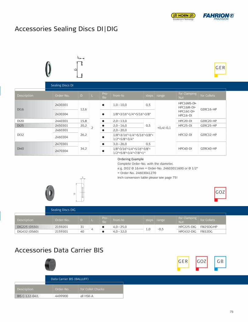
73
DI162430301
12,6
2
1,0 – 10,0 0,5
+0,4/-0,1
HPC16MS-DI•HPC16M-DI•HPC16C-DI•HPC16-DI
GERC16-HP2430304 1/8“•3/16”•1/4”•5/16”•3/8”
DI20 2440301 15,8 2,0 – 13,00,5
HPC20-DI GERC20-HPDI25 2450301 20,2 2,0 – 16,0 HPC25-DI GERC25-HP
DI322460301
26,22,0 – 20,0
HPC32-DI GERC32-HP2460304
1/8”•3/16”•1/4”•5/16”•3/8”•1/2“•5/8“•3/4“
DI402470301
34,23,0 – 26,0 0,5
HPC40-DI GERC40-HP2470304
1/8”•3/16”•1/4”•5/16”•3/8”•1/2“•5/8“•3/4“•7/8“•1“
DIG225 (DS50) 2159201 314
4,0 – 25,01,0 -0,5
HPC225-DIG FM25DG•HPDIG432 (DS60) 2159301 40 4,0 – 32,0 HPC432-DIG FM32DG
BIS C-122-04/L 4499900 Все HSK-A
Precision Collets GOZ-DG-HP (double slotted) – 3 μm
Precision Collets GOZ-DG (double slotted) – 6 μm or 10 μm
Ordering ExampleComplete Order-No. with the diameter, e.g. FM25DG-HP Ø 20 mm = Order-No. 12242012000
Ordering ExampleComplete Order-No. with the diameter, e.g. FM25DG Ø 16 mm = Order-No. 12202011600 or Ø 1/4“ = Order-No. 12202040635Inch conversion table please see page 75!
Accessories Sealing Discs DI | DIG
Accessories Data Carrier BIS
Sealing Discs DI
Sealing Discs DIG
Data Carrier BIS (BALLUFF)
Ordering ExampleComplete Order-No. with the diameter, e.g. DI32 Ø 16 mm = Order-No. 24603011600 or Ø 1/2“ = Order-No. 24603041270 Inch conversion table please see page 75!
Description Order-No. D LPro-£ le
from-to steps rangefor Clamping Nut
for Collets
Description Order-No. for Collet Chucks
Description Order-No. D LPro-£ le
from-to steps rangefor Clamping Nut
for Collets
BIS C-122-04/L 4499900 all HSK-A
G ER
GOZ
G ER GOZ G B
L
D
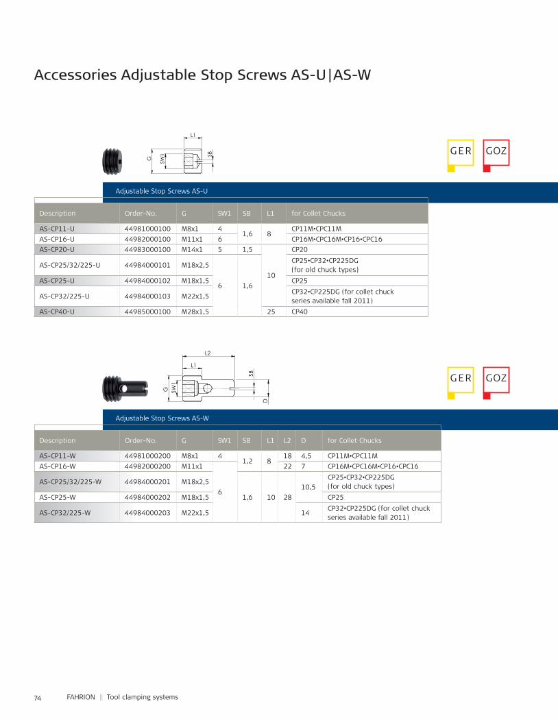
74 FAHRION || Tool clamping systems
Accessories Adjustable Stop Screws AS-U | AS-W
Adjustable Stop Screws AS-U
Description Order-No. G SW1 SB L1 for Collet Chucks
Adjustable Stop Screws AS-W
Description Order-No. G SW1 SB L1 L2 D for Collet Chucks
AS-CP11-W 44981000200 M8x1 41,2 8
18 4,5 CP11M•CPC11MAS-CP16-W 44982000200 M11x1
6
22 7 CP16M•CPC16M•CP16•CPC16
AS-CP25/32/225-W 44984000201 M18x2,5
1,6 10 2810,5
CP25•CP32•CP225DG (for old chuck types)
AS-CP25-W 44984000202 M18x1,5 CP25
AS-CP32/225-W 44984000203 M22x1,5 14CP32•CP225DG (for collet chuckseries available fall 2011)
AS-CP11-U 44981000100 M8x1 41,6 8
CP11M•CPC11MAS-CP16-U 44982000100 M11x1 6 CP16M•CPC16M•CP16•CPC16AS-CP20-U 44983000100 M14x1 5 1,5
10
CP20
AS-CP25/32/225-U 44984000101 M18x2,5
6 1,6
CP25•CP32•CP225DG (for old chuck types)
AS-CP25-U 44984000102 M18x1,5 CP25
AS-CP32/225-U 44984000103 M22x1,5CP32•CP225DG (for collet chuckseries available fall 2011)
AS-CP40-U 44985000100 M28x1,5 25 CP40
G ER GOZ
G ER GOZ
SW1
G
L1
SB
L2
L1
D
SW1
G
SB
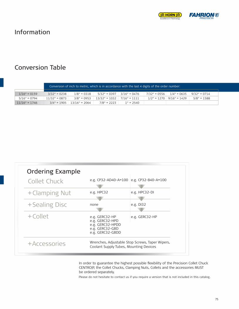
75
Adjustable Stop Screws AS-U
Adjustable Stop Screws AS-W
Conversion Table
In order to guarantee the highest possible ¸exibility of the Precision Collet Chuck CENTRO|P, the Collet Chucks, Clamping Nuts, Collets and the accessories MUST be ordered separately.Please do not hesitate to contact us if you require a version that is not included in this catalog.
e.g. CP32-AD40-A=100 e.g. CP32-B40-A=100
e.g. HPC32 e.g. HPC32-DI
none e.g. DI32
e.g. GERC32-HP e.g. GERC32-HPe.g. GERC32-HPDe.g. GERC32-HPDDe.g. GERC32-GBDe.g. GERC32-GBDD
Wrenches, Adjustable Stop Screws, Taper Wipers, Coolant Supply Tubes, Mounting Devices
Collet Chuck
+ Clamping Nut
+ Sealing Disc
+ Collet
+ Accessories
Ordering Example
Information
Conversion of inch to metric, which is in accordance with the last 4 digits of the order number:
1/16“ = 0159 3/32“ = 0238 1/8“ = 0318 5/32“ = 0397 3/16“ = 0476 7/32“ = 0556 1/4“ = 0635 9/32“ = 07145/16“ = 0794 11/32“ = 0873 3/8“ = 0953 13/32“ = 1032 7/16“ = 1111 1/2“ = 1270 9/16“ = 1429 5/8“ = 1588
11/16“ = 1746 3/4“ = 1905 13/16“ = 2064 7/8“ = 2223 1“ = 2540
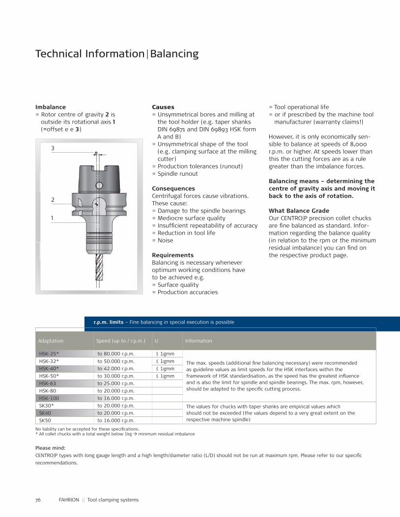
76 FAHRION || Tool clamping systems
Technical Information | Balancing
HSK-25* to 80.000 r.p.m. ≤ 1gmm
The max. speeds (additional £ ne balancing necessary) were recommendedas guideline values as limit speeds for the HSK interfaces within theframework of HSK standardisation, as the speed has the greatest in ̧uenceand is also the limit for spindle and spindle bearings. The max. rpm, however, should be adapted to the speci£ c cutting process.
HSK-32* to 50.000 r.p.m. ≤ 1gmmHSK-40* to 42.000 r.p.m. ≤ 1gmmHSK-50* to 30.000 r.p.m. ≤ 1gmmHSK-63 to 25.000 r.p.m.HSK-80 to 20.000 r.p.m.HSK-100 to 16.000 r.p.m.SK30* to 20.000 r.p.m. The values for chucks with taper shanks are empirical values which
should not be exceeded (the values depend to a very great extent on therespective machine spindle)
SK40 to 20.000 r.p.m.SK50 to 16.000 r.p.m.
r.p.m. limits – Fine balancing in special execution is possible
No liability can be accepted for these speci£ cations. * All collet chucks with a total weight below 1kg → minimum residual imbalance
Imbalance= Rotor centre of gravity 2 is outside its rotational axis 1 (=offset e e 3)
Causes= Unsymmetrical bores and milling at the tool holder (e.g. taper shanks DIN 69871 and DIN 69893 HSK form A and B) = Unsymmetrical shape of the tool (e.g. clamping surface at the milling cutter) = Production tolerances (runout)= Spindle runout
ConsequencesCentrifugal forces cause vibrations. These cause:= Damage to the spindle bearings= Mediocre surface quality= Insuf£ cient repeatability of accuracy= Reduction in tool life= Noise
RequirementsBalancing is necessary whenever optimum working conditions have to be achieved e.g. = Surface quality= Production accuracies
= Tool operational life= or if prescribed by the machine tool manufacturer (warranty claims!)
However, it is only economically sen-sible to balance at speeds of 8,000 r.p.m. or higher. At speeds lower than this the cutting forces are as a rule greater than the imbalance forces.
Balancing means – determining the centre of gravity axis and moving it back to the axis of rotation.
What Balance GradeOur CENTRO|P precision collet chucks are £ ne balanced as standard. Infor-mation regarding the balance quality (in relation to the rpm or the minimum residual imbalance) you can £ nd on the respective product page.
Adaptation Speed (up to / r.p.m.) U Information
Please mind:CENTRO|P types with long gauge length and a high length/diameter ratio (L/D) should not be run at maximum rpm. Please refer to our speci£ crecommendations.
3
2
1
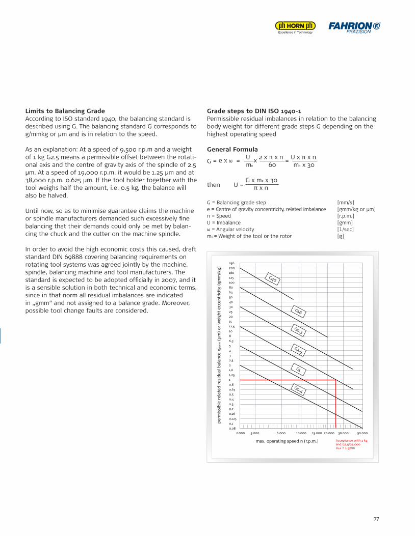
77
r.p.m. limits – Fine balancing in special execution is possible
Limits to Balancing GradeAccording to ISO standard 1940, the balancing standard is described using G. The balancing standard G corresponds to g/mmkg or μm and is in relation to the speed.
As an explanation: At a speed of 9,500 r.p.m and a weight of 1 kg G2.5 means a permissible offset between the rotati-onal axis and the centre of gravity axis of the spindle of 2.5 μm. At a speed of 19,000 r.p.m. it would be 1.25 μm and at 38,000 r.p.m. 0.625 μm. If the tool holder together with the tool weighs half the amount, i.e. 0.5 kg, the balance will also be halved.
Until now, so as to minimise guarantee claims the machine or spindle manufacturers demanded such excessively £ ne balancing that their demands could only be met by balan-cing the chuck and the cutter on the machine spindle.
In order to avoid the high economic costs this caused, draft standard DIN 69888 covering balancing requirements on rotating tool systems was agreed jointly by the machine, spindle, balancing machine and tool manufacturers. The standard is expected to be adopted of£ cially in 2007, and it is a sensible solution in both technical and economic terms, since in that norm all residual imbalances are indicated in „gmm“ and not assigned to a balance grade. Moreover, possible tool change faults are considered.
Grade steps to DIN ISO 1940-1Permissible residual imbalances in relation to the balancing body weight for different grade steps G depending on the highest operating speed
General Formula
G = e x ω = U x 2 x π x n
= U x π x n
mR 60 mR x 30
then U = G x mR x 30
π x n
G = Balancing grade step [mm/s]e = Centre of gravity concentricity, related imbalance [gmm/kg or µm]n = Speed [r.p.m.]U = Imbalance [gmm]ω = Angular velocity [1/sec]mR = Weight of the tool or the rotor [g]
perm
issi
ble
rela
ted
resi
dual
bal
ance
epe
rm (
μm)
or w
eigh
t ec
cent
ricit
y (g
mm
/kg)
max. operating speed n (r.p.m.)
2.000 3.000 6.000 10.000 15.000 20.000 30.000 50.000
Acceptance with 1 kg and G2,5/25.000 Uzul = 1 gmm
0,080,10,1250,160,20,30,40,50,630,811,251,622,53456,381012,51520253040506380100125160200250
G40
G16
G6,3
G2,5
G1
G0,4
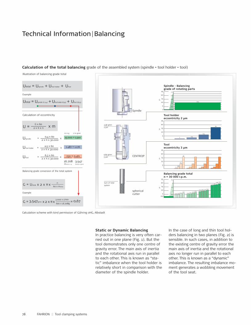
78 FAHRION || Tool clamping systems
Calculation of the total balancing grade of the assembled system (spindle • tool holder • tool)
Technical Information | Balancing
Calculation scheme with kind permission of Gühring oHG, Albstadt
U = G x 60 x m 2 x π x n
G = Utotal x 2 x π x n 60 x mtotal
G = 3,547gmm x 2 x π x 3.000 x 1/min = 0,67
60s x 16.708g
Utotal = USpindle (G 0,4) + UTool holder (G2,5) + UTool (G6,3)
Utotal = USpindle + UTool holder + UTool
Example
Example
Balancing grade conversion of the total system
Calculation of eccentricity
Illustration of balancing grade total
= 0,4 x 60 x 15.000 = 1,910 2 x π x 30.000USpindle
= 2,5 x 60 x 1.487 = 1,176 2 x π x 30.000UTool holder
= 6,3 x 60 x 230 = 0,461 2 x π x 30.000UTool
m in g U in gmm
16.708 mtotal in g
3,547Utotal in gmm
Spindle
CENTRO|P
spherical cutter
2,96 gmm2 µm
0,69 gmm3 µm
Sum of totalsystem
25
20
15
10
5
Tooleccentricity 3 µm
G
12,5
6,3
16
25
20
15
10
5
Tool holdereccentricity 2 µm
1
G
2,5
6,3
16
25
20
15
10
5
1
1,0
0,8
0,6
0,4
0,2
Spindle - Balancinggrade of rotating parts
0,4G
25
20
15
10
5
2,5
2
1,5
1
0,5
Balancing grade totaln = 30 000 r.p.m.
G
0,46 0,48 0,540,67
0,59 0,61 0,670,79
0,93 0,95 1,00 1,14
1,79 1,811,86 1,99
2,5
Static or Dynamic BalancingIn practice balancing is very often car-ried out in one plane (Fig. 1). But the tool demonstrates only one centre of gravity error. The main axis of inertia and the rotational axis run in parallel to each other. This is known as “sta-tic” imbalance when the tool holder is relatively short in comparison with the diameter of the spindle holder.
In the case of long and thin tool hol-ders balancing in two planes (Fig. 2) is sensible. In such cases, in addition to the existing centre of gravity error the main axis of inertia and the rotational axis no longer run in parallel to each other. This is known as a “dynamic” imbalance. The resulting imbalance mo-ment generates a wobbling movement of the tool seat.
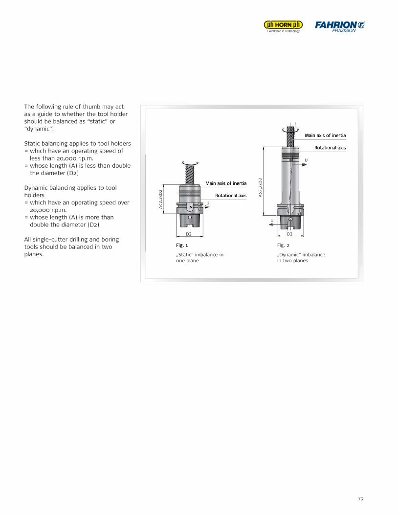
79
The following rule of thumb may act as a guide to whether the tool holder should be balanced as “static” or “dynamic”:
Static balancing applies to tool holders = which have an operating speed of less than 20,000 r.p.m.= whose length (A) is less than double the diameter (D2)
Dynamic balancing applies to tool holders = which have an operating speed over 20,000 r.p.m.= whose length (A) is more than double the diameter (D2)
All single-cutter drilling and boring tools should be balanced in twoplanes.
Fig. 1
„Static“ imbalance in one plane
Fig. 2
„Dynamic“ imbalance in two planes
Rotational axis
Main axis of inertia
Rotational axis
Main axis of inertia
Rotational axis
Main axis of inertia
Rotational axis
Main axis of inertia
Fig. 1
Rotational axis
Main axis of inertia
Rotational axis
Main axis of inertia
A<2,
2xD
2
A>2,
2xD
2
D2 D2
U
U
U
FAHRION Vertriebs-GmbHForststraße 5473667 KaisersbachGermanyPhone +49 7184 9282-0Fax +49 7184 [email protected]
FAHRION and Horn – Partners in Technology
FAHRION offers a wide selection of precision collets, precision collet chucks as well as precision products for workpiece clam-ping which ful£ ll maximum requirements in terms of concentri-city, service life and manufacuring quality. In doing so, FAHRION pays particular attention to user-friendly technology oriented towards the practical requirements of the users, which is cons-tantly advanced.
KFAH
RIO
NU
S-4 .
17
m
edie
nmal
er.d
e
Horn USA, Inc.320 Premier Court, Suite 205 Franklin, TN 37067 USAPhone +1 888 818-4676Fax +1 615 [email protected] www.hornusa.com