Embed Size (px)
Citation preview

GP SERIESGP-12K/GP-20K/GP-22K/GP-30K
GP-40K/GP-60K/GP-100K/GP-102KGP-30KS/GP-100KS
Precision Balance
INSTRUCTION MANUAL
WM:PD4000273A

© 2002 A&D Company Ltd. All rights reserved.No part of this publication may be reproduced, transmitted, transcribed, or translated intoany language in any form by any means without the written permission of A&D CompanyLtd.
The contents of this manual and the specifications of the instrument covered by thismanual are subject to change for improvement without notice.

1
CONTENTSBasic operation
1. INTRODUCTION ...............................................................................................................................31-1 About This Manual .............................................................................................................................. 31-2 Features.............................................................................................................................................. 31-3 Compliance ......................................................................................................................................... 4
2. UNPACKING THE BALANCE ..........................................................................................................52-1 Unpacking ........................................................................................................................................... 52-2 Installing the Balance.......................................................................................................................... 6
3. PRECAUTIONS.................................................................................................................................73-1 Before Use .......................................................................................................................................... 73-2 During Use .......................................................................................................................................... 73-3 After Use ............................................................................................................................................. 93-4 Power Supply...................................................................................................................................... 93-5 Display Symbols and Key Operation ................................................................................................ 103-6 Smart Range Function...................................................................................................................... 11
4. WEIGHING UNITS ..........................................................................................................................124-1 Units .................................................................................................................................................. 124-2 Changing the Units ........................................................................................................................... 15
5. WEIGHING ......................................................................................................................................155-1 Basic Operation (Kilogram Mode)..................................................................................................... 155-2 Counting Mode (PCS)....................................................................................................................... 165-3 Percent Mode (%)............................................................................................................................. 185-4 Animal Weighing Mode (Hold Function) ........................................................................................... 185-5 Accumulation Function...................................................................................................................... 19
Adapting to the environment
6. RESPONSE ADJUSTMENT / SELF CHECK FUNCTION.............................................................216-1 Automatic Response Adjustment / Self Check Function................................................................... 216-2 Manual Response Adjustment .......................................................................................................... 22
7. CALIBRATION ................................................................................................................................237-1 Calibration Group.............................................................................................................................. 237-2 Automatic Self Calibration (Calibration due to changes in temperature) ................................................. 247-3 Calibration Using the Internal mass (One-Touch Calibration) .......................................................... 247-4 Calibration Using an External Weight ............................................................................................... 257-5 Calibration Test Using an External Weight ....................................................................................... 277-6 Correcting the Internal Mass Value................................................................................................... 28
8. FUNCTION SWITCH AND INITIALIZATION ..................................................................................308-1 Permit or Inhibit................................................................................................................................. 308-2 Initializing the Balance ...................................................................................................................... 31
9. FUNCTION TABLE .........................................................................................................................329-1 Structure and Sequence of the Function Table................................................................................. 329-2 Display and Keys .............................................................................................................................. 329-3 Details of the Function Table............................................................................................................. 339-4 Description of the Class “Environment, Display” .............................................................................. 369-5 Description of the Item “Data output mode”...................................................................................... 389-6 Description of the Item “Data format”................................................................................................ 399-7 Description of the Data Format Added to the Weighing Data.................................................................. 41
2
9-8 Data Format Examples .....................................................................................................................429-9 Clock and Calendar Function............................................................................................................449-10 Comparator Function ......................................................................................................................469-11 Adding the Comparison Results ......................................................................................................489-12 Main Display Comparison Function ................................................................................................48
10. ID NUMBER AND GLP REPORT.................................................................................................5010-1 Setting the ID Number ....................................................................................................................5010-2 GLP Report .....................................................................................................................................51
11. DATA MEMORY.............................................................................................................................5411-1 Notes on Using Data Memory .........................................................................................................5411-2 Memory for Weighing Data..............................................................................................................5511-3 Memory for Calibration and Calibration Test Data ..........................................................................5811-4 Memory for Unit Mass in the Counting Mode..................................................................................5911-5 Memory for Comparator Settings ....................................................................................................6111-6 Memory for Tare Value ....................................................................................................................6311-7 Data Memory: Quick Selection Mode..............................................................................................6711-8 Data Memory: Confirmation and Storage Mode..............................................................................68
12. PROGRAMMABLE-UNIT .............................................................................................................69
13. DENSITY MEASUREMENT..........................................................................................................70
RS-232C serial interface
14. I/O UNIT SPECIFICATIONS (Standard) ......................................................................................7314-1 RS-232C//External Contact Input ..........................................................................................................73
15. CONNECTION TO PERIPHERAL EQUIPMENT .........................................................................7515-1 Connection to the AD-8121 Printer .................................................................................................7515-2 Connection to a Computer ..............................................................................................................7515-3 Using Windows Communication Tools (WinCT) .............................................................................7615-4 Using the WinCT software, the balance can do the following:........................................................76
16. COMMANDS .................................................................................................................................7716-1 Command List .................................................................................................................................7716-2 Acknowledge Code and Error Codes..............................................................................................7816-3 Control Using CTS and RTS...........................................................................................................7816-4 Settings Related to RS-232C..........................................................................................................78
Maintenance
17. MAINTENANCE ............................................................................................................................79
18. TROUBLESHOOTING..................................................................................................................7918-1 Checking the Balance Performance and Environment ...................................................................7918-2 Error Codes.....................................................................................................................................8018-3 Asking For Repair............................................................................................................................82
19. SPECIFICATIONS.........................................................................................................................83
20. EXTERNAL DIMENSIONS ...........................................................................................................84
21. OPTIONS.......................................................................................................................................86
22. TERMS/INDEX ..............................................................................................................................87

3
1. INTRODUCTIONThis manual describes how the GP series balance works and how to get the most out of it in terms ofperformance.
Read this manual thoroughly before using the balance and keep it at hand for future reference.
1-1 About This ManualThis manual consists of the following five parts:
Basic operation ............................... Describes precautions on handling the balance, balanceconstruction and basic balance operation.
Adapting to the environment........... Describes response adjustment, calibration and calibrationtest.
Functions ........................................ Describes various functions of the balance.
RS-232C serial interface ................... Describes RS-232C serial interface output and external contactinput. The RS-232C serial interface outputs weighing data andcontrols the balance. The external contact input commands thebalance re-zeroing and data output.
Maintenance ................................... Describes maintenance, error codes, troubleshooting,specifications and options.
1-2 Features� Large Vacuum Fluorescent Display, easy to read.
� Dust-tight and Protected Against Water Jets (Complying with IP65), allows washing with water.
� Built-in Calibration Weight (hereinafter referred to as internal mass), allows easy calibration,adjustment and maintenance of the balance.
� Automatic Self Calibration, using the internal mass, adapting to changes in temperature.
� Self Check Function, provided to self-check the balance using the internal mass.
� Automatic Response Adjustment, adapting to vibration and drafts in the environment.
� High Response Speed, the time to read a displayed value after a sample is placed on the panhas been shortened by using the Super Hybrid Sensor (SHS). (Approx. 1.5 seconds whenFAST is selected for the response rate.)
� Data Memory Function, storing weighing data, calibration data or unit mass in the countingmode. It can also store tare values or upper and lower limit values for the comparator function.Interval Memory Mode is provided to store the weighing data periodically.
� Good Laboratory Practice (GLP) data output using the standard RS-232C serial interface.
� Clock and Calendar Function, adding the time and date to the output data.
� Comparator Indicators, displaying the comparison results, H I, OK or LO.

4
� Capacity Indicator, displaying the weight value in percentage relative to the weighing capacity.
� Hold Function, provided for weighing a moving object such as an animal.
� Multiple Weighing Units, with most of the common units used around the world.
� Density Mode, for calculating the density of a solid.
� Accumulation Function, adding the weight values and outputting the sum.
� Adjustable Display Position, the standard type balance has a swing-arm to adjust the displayposition for optimum viewing.Separate display type balances (GP-30KS/100KS) are also available.
� Windows Communication Tools (WinCT), allows easy communication with Windows 95/98.Windows is a registered trademark of Microsoft Corporation.
� Reference Card, provided for a quick reference to the balance operation.
� Underhook, available as an option, for measuring density and weighing magnetic materials.
� Comparator Output (OP-04) and Analog Voltage Output (OP-06) are available as options.
1-3 ComplianceCompliance with FCC Rules
Please note that this equipment generates, uses and can radiate radio frequency energy. Thisequipment has been tested and has been found to comply with the limits of a Class Acomputing device pursuant to Subpart J of Part 15 of FCC rules. These rules are designed toprovide reasonable protection against interference when equipment is operated in acommercial environment. If this unit is operated in a residential area, it may cause someinterference and under these circumstances the user would be required to take, at his ownexpense, whatever measures are necessary to eliminate the interference.
(FCC = Federal Communications Commission in the U.S.A.)
Compliance with EMC Directives
This device features radio interference suppression in compliance with valid EC
Regulation 89/336/EEC.

5
2. UNPACKING THE BALANCE2-1 Unpacking
� The balance is a precision instrument. Unpack the balance carefully. Keep the packing materialto be used for transporting the balance in the future.
� The packing contents depend on the balance model. See the illustrations to confirm thateverything is contained.
Standard type: GP-12K/20K/22K/30K/40K/60K/100K/102K
Note
Please confirm that the AC adapter type is correctfor your local voltage and receptacle type.

6
Separate display type: GP-30KS/100KS
Note
Please confirm that the AC adapter type is correctfor your local voltage and receptacle type.
2-2 Installing the BalanceInstall the balance as follows:
1. Refer to “3. PRECAUTIONS” for installing the balance.
2. Adjust the leveling feet to level the balance. Confirm it using the bubble spirit level.
3. Confirm that the adapter type is correct for the local voltage and power receptacle type.
4. Connect the AC adapter to the balance. Warm up the balance for at least 30 minutes withnothing on the weighing pan.

7
3. PRECAUTIONSTo get the optimum performance from the balance and acquire accurate weighing data, note the
following:
3-1 Before Use� Install the balance in an environment where the
temperature and humidity are not excessive. The bestoperating temperature is about 20°C / 68°F at about50% relative humidity.
� Install the balance where it is not exposed to direct sunlightand it is not affected by heaters or air conditioners.
� Install the balance where it is free of dust.
� Install the balance away from equipment whichproduces magnetic fields.
� Install the balance in a stable place avoiding vibrationand shock. Corners of rooms on the first floor are best,as they are less prone to vibration.
� The weighing table should be solid and free fromvibration, drafts and as level as possible.
� Level the balance by adjusting the leveling feet andconfirm it using the bubble spirit level.
� Ensure a stable power source when using the AC adapter.
� Plug in the AC adapter and warm up the balance for atleast 30 minutes.
� Calibrate the balance periodically for accurate weighing.
� When the balance is installed for the first time or has beenmoved, warm up the balance for at least 12 hours to allowthe balance to reach equilibrium with the ambienttemperature, and then perform calibration before use.
CautionDo not install the balance where flammable or corrosive gas is present.
3-2 During Use� Discharge static electricity from the material to be
weighed (hereinafter referred to as sample). When asample could have a static charge, the weighing data isinfluenced. Try to keep the ambient humidity above45%RH or use the metal shield case.
8
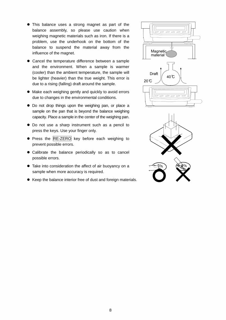
� This balance uses a strong magnet as part of thebalance assembly, so please use caution whenweighing magnetic materials such as iron. If there is aproblem, use the underhook on the bottom of thebalance to suspend the material away from theinfluence of the magnet.
� Cancel the temperature difference between a sampleand the environment. When a sample is warmer(cooler) than the ambient temperature, the sample willbe lighter (heavier) than the true weight. This error isdue to a rising (falling) draft around the sample.
� Make each weighing gently and quickly to avoid errorsdue to changes in the environmental conditions.
� Do not drop things upon the weighing pan, or place asample on the pan that is beyond the balance weighingcapacity. Place a sample in the center of the weighing pan.
� Do not use a sharp instrument such as a pencil topress the keys. Use your finger only.
� Press the RE-ZERO key before each weighing toprevent possible errors.
� Calibrate the balance periodically so as to cancelpossible errors.
� Take into consideration the affect of air buoyancy on asample when more accuracy is required.
� Keep the balance interior free of dust and foreign materials.

9
3-3 After Use� Avoid mechanical shock to the balance.
� Do not disassemble the balance. Contact the local A&D dealer if the balance needs service or repair.
� Do not use organic solvents to clean the balance. Clean the balance with a lint free cloth that ismoistened with warm water and a mild detergent.
� Do not allow the balance to be immersed in water. Even though the balance complies with IP65(Dust-tight and Protected Against Water Jets), the balance will not withstand being completelyimmersed in water.
� Do not remove the AC adapter while the internal mass is in motion, for example, right after theAC adapter is connected, or during calibration using the internal mass.If the AC adapter is removed under the conditions described above, the internal mass will beleft unsecured, that may cause mechanical damage when the balance is moved.
Remove the AC adapter as follows:
1 Press the ON:OFF key. Confirm that 0(zero) is displayed.
2 After the zero display confirmation, pressthe ON:OFF key to turn the display off.
3 Remove the AC adapter.
3-4 Power Supply� When the AC adapter is connected, the balance is in the standby mode if the standby indicator
is on (refer to “3-5 Display Symbols and Key Operation”). This is a normal state and does notharm the balance. For accurate weighing, keep the AC adapter connected to the balance and ACpower unless the balance is not to be used for a long period of time.
The illustration above is adisplay example.The decimal point positionand the unit depends on thebalance model and thesettings.

10
3-5 Display Symbols and Key OperationKey operationKey operation affects how the balance functions. The basic key operations are:
� “Press and release the key immediately” or “Press the key”= normal key operation during measurement
� “Press and hold the key”
Display symbols
Each key, when pressed or when pressed and held, functions as follows:
Key When pressed When pressed and heldTurns the display ON and OFF. The standby indicator is displayed when the display isturned off. The weighing mode is enabled when the display is turned on.This key is available anytime. Pressing the key during operation will interrupt theoperation and turn the display OFF.
In the weighing mode, turns the minimumweighing value ON and OFF.
In the counting or percent mode, entersthe sample storing mode.
Enters the function table mode. Refer to“9. FUNCTION TABLE”.
Switches the weighing units stored in thefunction table. Refer to “4. WEIGHINGUNITS”.
Performs response adjustment and selfcheck.
Performs calibration of the balance usingthe internal mass.
Displays other items of the calibrationmenu.
Stores the weighing data in memory oroutputs to a printer or personal computerdepending on the function table settings.(Factory setting = output)
No function at the factory setting
By changing the function table:Outputs “Title block” and “End block” forGLP report.Displays the data memory menu.
Sets the display to zero.

11
3-6 Smart Range FunctionThe GP-22K and GP-102K are equipped with two ranges. The precision range has a higher
resolution. The standard range has normal resolution.
The range is switched automatically, depending on the value displayed. Pressing the RE-ZERO key
allows weighing in the precision range, regardless of the tare value. (Smart range function)
The range can be fixed to the standard range, by pressing the SAMPLE key.
NoteOnce the range is switched to the standard range, it will not switch to the precision rangeautomatically even when the displayed value becomes within the precision range value. Usethe RE-ZERO or SAMPLE key to activate the precision range again.
Below is a description of how the Smart Range actually functions, using the GP-102K
(Precision range=61 kg×1 g, Standard range=101 kg×10 g)
1 Press the RE-ZERO key.The balance will start weighing, using theprecision range.
2 Place a container, on the weighing pan, to beused as a tare.The value displayed exceeds the precisionrange value. So, the range will be switched tothe standard range.
3 Press the RE-ZERO key.The balance will be switched to the precisionrange.
4 Place a sample on the pan.The value displayed is within the precisionrange value. So, the balance will perform aweighing, using the precision range.
Precision range/standard range valueGP-22K GP-102K
Precision range(after RE-ZERO is pressed)
Up to 6.1009 kg Up to 61.009 kg
Standard range 6.101 to 21.008 kg 61.01 to 101.08 kg

12
4. WEIGHING UNITS4-1 UnitsWith the GP series balance, the following weighing units and weighing modes are available :
A unit or mode can be selected and stored in the function table as described in “4-2 Changing the Units”.If a weighing mode (or unit of weight) has been turned off, that mode or unit will be missing in thesequence. Tael has four varieties, one of which can be selected and installed at the factory.
For details about the units and modes, see the table below:
Name (unit, mode) Abbrev. Display Function table(Storing mode)
Conversion factor1 g =
Gram g G 1 gkilogram kg 1000 gCounting mode PCS Percent mode Ounce (Avoir) OZ 28.349523125 gPound Lb 453.59237 gPound/Ounce L OZ l0 1Lb=16 oz,
1 oz=28.349523125 gTroy Ounce OZt 31.1034768 gMetric Carat ct 0.2 gMomme mom 3.75 gPennyweight dwt 1.55517384 gTael (HK general, Singapore) 37.7994 gTael (HK jewelry) 37.429 gTael (Taiwan) 37.5 gTael (China)
TL
31.25 gTola (India) t 11.6638038 gMessghal MS 4.6875 gDensity mode
DS
is used toshow the density.
Programmable-unit (Multi-unit) Mlt
Note: The units, g, ct and dwt are not available for the GP-102K.

13
The tables below indicate the weighing capacity and the minimum display for each unit, depending on
the balance model.
GP-12K GP-20K GP-30K
GP-30KS
GP-40KUnit
Capacity Minimum display Capacity Minimum display
Gram 12000.0 21000.0 31000.0 0.1 41000.0 0.5
Kilogram 12.0000 21.0000 31.0000 0.0001 41.0000 0.0005
Ounce (Avoir) 423.290 740.755 1093.495 0.005 1446.24 0.02
Pound 26.4555 46.2970 68.3435 0.0005 90.390 0.002
Pound/Ounce 26L 7.29 46L 4.75 68L 5.49 0.01 90L 6.24 0.02
Troy Ounce 385.810 675.170 996.673 0.005 1318.18 0.02
Metric Carat 60000.0 105000.0 155000.0 0.5 205000 5
Momme 3200.00 5600.00 8266.65 0.05 10933.4 0.2
Pennyweight 7716.2 13503.3 19933.5 0.1 26363.5 0.5
Tael (HK general,Singapore)
317.465 555.565 820.120 0.005 1084.68 0.02
Tael (HK jewelry) 320.605 561.060 828.235 0.005 1095.40 0.02
Tael (Taiwan) 320.000 560.000 826.665 0.005 1093.34 0.02
Tael (China) 384.000 672.000 992.000 0.005 1312.00 0.02
Tola (India) 1028.82 1800.44 2657.80 0.01 3515.15 0.05
Messghal 2560.00 4480.00 6613.35 0.05 8746.6 0.2
GP-60K GP-100K
GP-100KSUnit
Capacity Minimum display
Gram 61000 101000 1
Kilogram 61.000 101.000 0.001
Ounce (Avoir) 2151.70 3562.65 0.05
Pound 134.480 222.665 0.005
Pound/Ounce 134L 7.7 222L 10.7 0.1
Troy Ounce 1961.20 3247.25 0.05
Metric Carat 305000 505000 5
Momme 16266.5 26933.5 0.5
Pennyweight 39224 64945 1
Tael (HK general,Singapore)
1613.80 2672.00 0.05
Tael (HK jewelry) 1629.75 2698.45 0.05
Tael (Taiwan) 1626.65 2693.35 0.05
Tael (China) 1952.00 3232.00 0.05
Tola (India) 5229.9 8659.3 0.1
Messghal 13013.5 21546.5 0.5

14
GP-22K
Standard range Precision range
Unit
Capacity Minimum display Capacity Minimum display
Gram 21000 1 6100.0 0.1
Kilogram 21.000 0.001 6.1000 0.0001
Ounce (Avoir) 740.75 0.05 215.170 0.005
Pound 46.295 0.005 13.4480 0.0005
Pound/Ounce 46L 4.8 0.1 13L 7.17 0.01
Troy Ounce 675.15 0.05 196.120 0.005
Metric Carat 105000 5 30500.0 0.5
Mom me 5600.0 0.5 1626.65 0.05
Pennyweight 13503 1 3922.4 0.1
Tael (HK general,Singapore)
555.55 0.05 161.380 0.005
Tael (HK jewelry) 561.05 0.05 162.975 0.005
Tael (Taiwan) 560.00 0.05 162.665 0.005
Tael (China) 572.00 0.05 195.200 0.005
Tola (India) 1800.4 0.1 522.99 0.01
Messghal 4480.0 0.5 1301.35 0.05
GP-102K
Standard range Precision range
Unit
Capacity Minimum display Capacity Minimum display
Gram - - - -
Kilogram 101.00 0.01 61.000 0.001
Ounce (Avoir) 3562.5 0.5 2151.70 0.05
Pound 222.65 0.05 134.480 0.005
Pound/Ounce 222L 11 1 134L 7.7 0.1
Troy Ounce 3247.0 0.5 1961.20 0.05
Metric Carat - - - -
Momme 26935 5 16266.5 0.5
Pennyweight - - - -
Tael (HK general,Singapore)
2672.0 0.5 1613.80 0.05
Tael (HK jewelry) 2698.5 0.5 1629.75 0.05
Tael (Taiwan) 2693.5 0.5 1626.65 0.05
Tael (China) 3232.0 0.5 1952.00 0.05
Tola (India) 8659 1 5229.9 0.1
Messghal 21545 5 13013.5 0.5

15
4-2 Changing the UnitsThe units or modes can be selected and stored in the function table. The sequence of displaying theunits or modes can be arranged so as to fit the frequency of use in the function table.
Select a unit or mode and arrange the sequence of display as follows:1 Press and hold the SAMPLE key until ba5fnc of the
function table is displayed, then release the key.
2 Press the SAMPLE key several times to displayUnit .
3 Press the PRINT key to enter the unit selection mode.
4 Specify a unit or mode in the order to be displayedusing the following keys.
SAMPLE key To sequentially display the units.
RE-ZERO key To specify a unit or mode. Thestabilization indicator appears when thedisplayed unit or mode is specified.
5 Press the PRINT key to store the units or modes. The balance displays end and then displays thenext menu item of the function table.
6 Press the CAL key to exit the function table. Then the balance returns to the weighing modewith the selected unit.
5. WEIGHING5-1 Basic Operation (Kilogram Mode)
1 Place a container on the weighing pan, if necessary.Press the RE-ZERO key to cancel the weight (tare). Thebalance displays 0.0000 kg. (The decimal point positiondepends on the balance model.)
2 Place a sample on the pan or in the container.
3 Wait for the stabilization indicator to be displayed. Readthe value.
4 Remove the sample and container from the pan.
NotesTo use another unit, press the MODE key and select anappropriate unit.Press the SAMPLE key to turn on or off the minimumweighing value.The weighing data can be stored in memory. For details,refer to “11. DATA MEMORY”.

16
5-2 Counting Mode (PCS)This is the mode to determine the number of objects in a sample based on the standard sample unitmass. Unit mass means the mass of one sample. The smaller the variables in each sample unit massis, the more accurate the counting will be. The GP series balance is equipped with the AutomaticCounting Accuracy Improvement (ACAI) function to improve the counting accuracy.
NoteIf the sample unit mass variable, the difference from sample to sample, is too large, it maycause a counting error.
Selecting the counting mode1 Press the MODE key to select pcs (counting mode).
Storing a sample unit mass (Weighing input mode)2 Press the SAMPLE key to enter the sample unit mass
storing mode.
3 To select the number of samples, press the SAMPLE keyseveral times. It may be set to 10, 25, 50 or 100.
NoteA greater number of samples will yield more accuratecounting result.
4 Place a container on the weighing pan, if necessary.Press the RE-ZERO key to cancel the weight (tare). Thenumber specified in step 3 appears.e.g.: 25 0 pcs is displayed if 25 is selected in step 3.
5 Place the number of samples specified on the pan. In thisexample, 25 pieces.
6 Wait for the stabilization indicator to come on. Press thePRINT key to calculate and store the unit mass. Thebalance displays 25 pcs (counting mode) and is set tocount samples with this unit mass. (The sample unit massstored, even if the AC adapter is removed, is maintainedin non-volatile memory.)
To improve the accuracy of the unit mass, proceed to step 8.
NotesIf the balance judges that the mass of the samples is toolight and can not be stored as the unit mass, it displayslllloooo .If the balance judges that the mass of the samples is too light to aquire accurate weighing, itdisplays an error requiring the addition of more samples to the specified number. In theexample above, 150-50-50-50- pcs appears, requiring 25 more samples. Add 25 samples and pressthe PRINT key. When the unit mass is stored correctly, the balance proceeds to the counting mode.

17
Key entry of the unit mass value (digital input mode) is possible. For details, refer to “11-4Memory for Unit Mass in the Counting Mode”
Counting operation7 Place the samples to be counted on the pan.
Note Up to 50 unit masses can be stored in memory for the multiple sample. For details, refer to“11. DATA MEMORY”.
Counting mode using the ACAI functionThe ACAI is a function that improves the accuracy of the unitmass automatically by increasing the number of samples asthe counting process proceeds.
8 If a few more samples are added, the processing indicator turns on. To prevent an error, addthree or more. The processing indicator does not turn on if overloaded. Try to add the samenumber of samples as displayed.
9 The balance re-calculates the unit mass while the processing indicator is blinking. Do not touchthe balance or samples on the pan until the processing indicator turns off.
10 Counting accuracy is improved when the processing indicator turns off.
Each time the above operation is performed, a more accurate unit mass will be obtained.There is no definite upper limit of ACAI range for the number of samples exceeding 100. Try toadd the same number of samples as displayed.
11 Remove all the samples used in ACAI and proceed with the counting operation using theimproved unit mass.
NoteACAI will not function on the unit mass entered using the keys, or digital input mode.

18
5-3 Percent Mode (%)This is the mode to display the weight value in percentage compared to a 100% reference mass and
is used for target weighing or checking the sample variable.
Selecting the percent mode1 Press the MODE key to select % (percent mode). If
the percent mode can not be selected, refer to “4.WEIGHING UNITS”.
Storing the 100% reference mass2 Press the SAMPLE key to enter the 100% reference mass
storing mode.Even in the storing mode, pressing the MODE key willswitch to the next mode.
3 Place a container on the weighing pan, if necessary.Press the RE-ZERO key to cancel the weight (tare). Thebalance displays 100 0 % .
4 Place the sample to be set as the 100% reference masson the pan or in the container.
5 Press the PRINT key to store the reference mass. Thebalance displays 100.00 % . (The decimal point positiondepends on the reference value. The reference massstored, even if the AC adapter is removed, is maintainedin non-volatile memory.)
NoteIf the balance judges that the mass of the sample is toolight to be used as a reference, it displays lolololo .
6 Remove the sample.
Reading the percentage7 Place a sample to be compared to the reference mass on
the pan. The displayed percentage is based on the 100%reference mass.
5-4 Animal Weighing Mode (Hold Function)This is the mode to weigh a moving object such as an animal, even when the display of the weighingdata fluctuates. The hold function allows the average weight of the animal to be displayed.To use the hold function, set the function in the function table. For details, refer to “9. FUNCTIONTABLE” and “9-4 Description of the Class “Environment, Display””.
19
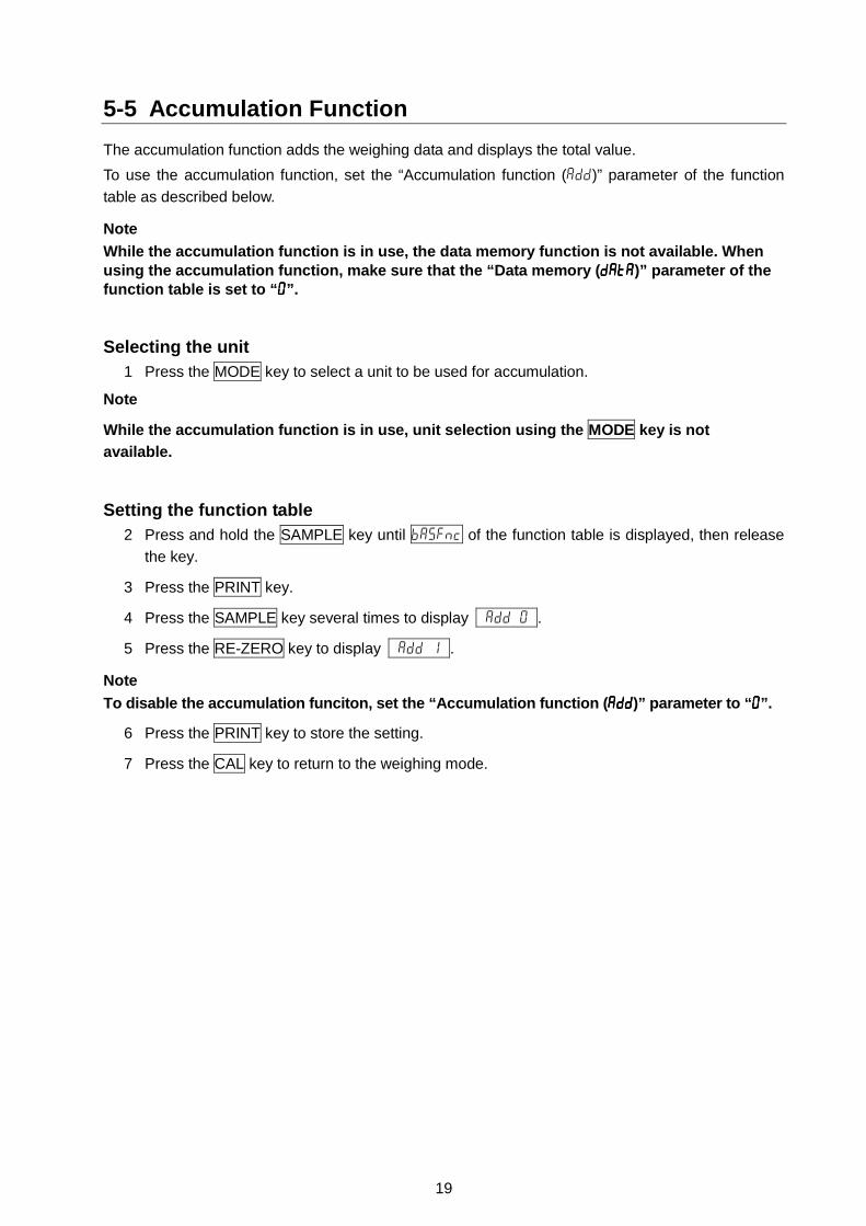
5-5 Accumulation FunctionThe accumulation function adds the weighing data and displays the total value.To use the accumulation function, set the “Accumulation function (add)” parameter of the functiontable as described below.
NoteWhile the accumulation function is in use, the data memory function is not available. Whenusing the accumulation function, make sure that the “Data memory (datadatadatadata)” parameter of thefunction table is set to “0000”.
Selecting the unit1 Press the MODE key to select a unit to be used for accumulation.
Note
While the accumulation function is in use, unit selection using the MODE key is notavailable.
Setting the function table2 Press and hold the SAMPLE key until ba5fnc of the function table is displayed, then release
the key.
3 Press the PRINT key.
4 Press the SAMPLE key several times to display add 0 .
5 Press the RE-ZERO key to display add 1 .
NoteTo disable the accumulation funciton, set the “Accumulation function (addaddaddadd)” parameter to “0000”.
6 Press the PRINT key to store the setting.
7 Press the CAL key to return to the weighing mode.

20
Using the accumulation functionUse the keys below to operate the accumulation function.
MODE key: Displays the weighing data and the total value alternately each time it is pressed.Will not change the unit while the accumulation function is in use.
RE-ZERO key: Sets the display to zero while the weighing data is displayed.Deletes the total value while the total value is displayed.
PRINT key Outputs and adds the weighing data while the weighing data is displayed.Outputs the total value while the total value is displayed.
1 Press the RE-ZERO key to set the displayto zero.
2 Place a sample on the pan. The weightvalue is displayed.
3 Press the PRINT key. The weight value isadded to the total and output.The accumulation number at the upper leftof the display increases by one.
4 Repeat steps 1-3 to accumulate more data.
5 Press the MODE key to display the totalvalue.
Outputting the value6 Press the PRINT key to output the total
value.
7 Press the RE-ZERO key to delete the totalvalue.
NotesThe output format depends on the functiontable setting.While the accumulation function is in use,the data memory function is not available.To disable the accumulation funciton, set the“Accumulation function (addaddaddadd)” parameter to “0000”.When the “Data number output (d-nod-nod-nod-no)”parameter is set to “1111”, the accumulationnumber will be output before the weighingdata.

21
6. RESPONSE ADJUSTMENT / SELF CHECK FUNCTIONThis function detects the influence on weighing that is caused by drafts and/or vibration at the placewhere the balance is installed and sets the response characteristic automatically. When this functionis selected, the balance self-checks the performance at the same time.
Two modes of response adjustment are available: automatic and manual.
The function has three rates as follows:
Changing the response rate changes the display refresh rate.Indicator Parameter Response characteristic Display refresh rateFAST Cond 0MID. Cond 1SLOW Cond 2
Fast response, Sensitive value Slow response, Stable value
If the response rate is changed as follows:MID. or SLOW FAST =10 times/secondFAST MID. or SLOW = 5 times/second
NoteTo set the refresh rate of 5 times/second when the response rate is FAST or 10 times/secondwhen the response rate is MID. or SLOW, change the “Display refresh rate (5555ppppdddd)” parameter of“Environment, Display (ba5fncba5fncba5fncba5fnc)” in the function table. For details, refer to “9. FUNCTIONTABLE”.
6-1 Automatic Response Adjustment / Self Check FunctionThis function automatically updates the response adjustment by analyzing the influence of theenvironment on the weighing data and also self-checks the balance performance using the internalmass.
Operation1 Press and hold the MODE key until RESPONSE is
displayed, then release the key.
2 The balance automatically starts to check the balanceperformance and sets the response characteristic.
CautionDo not allow vibration or drafts to affect the balanceduring adjustment.
3 After automatic adjustment, the balance displays theupdated response indicator and returns to the weighingmode. The response indicator remains displayed for awhile.
e.g. “ MID. OK ”
The example above indicates that the result of the selfcheck is good and MID. is selected as the responserate.

22
NotesIf improper performance is found in the self check, the balance displays CH noCH noCH noCH no. Contact thelocal A&D dealer for repair.If the automatic response adjustment fails, the balance displays CH ngCH ngCH ngCH ng. Check the ambientconditions such as breeze and vibration, also check the weigning pan. Then, perform theadjustment again. To return to the weighing mode, press the CAL key.If the automatic response adjustment is awkward, try to refine it using the manual responseadjustment.
6-2 Manual Response AdjustmentThis function manually updates the response adjustment.
Operation1 Press and hold the MODE key until RESPONSE is
displayed, then release the key.
And then, press the MODE key again quickly.
2 Press the MODE key to select a rate of the responseadjustment. Either FAST, MID. or SLOW can beselected.
3 After a few seconds of inactivity the balance displayseend . Then, it returns to the weighing mode anddisplays the updated response indicator. The responseindicator remains displayed for a while.
NoteThe response adjustment can be changed at “Condition(CondCondCondCond)” of “Environment, Display (ba5fncba5fncba5fncba5fnc)” in thefunction table. For details, refer to “9. FUNCTIONTABLE”.
23
7. CALIBRATION7-1 Calibration GroupThe GP series balance has the following modes as a calibration group.
Calibration � Automatic self calibration (calibration due to changes in temperature)� Calibration using the internal mass (one-touch calibration)� Calibration using an external weight
Calibration test � Calibration test using an external weight (Calibration test does notperform calibration.)
Correction of the internal mass value
TermsThe following terms are defined as follows:Internal mass = Built-in calibration weightExternal weight = A weight that you have. Referred to as a calibration weight when used for calibration.Calibration weight = A weight used for calibrationTarget weight = An external weight used for calibration test
Caution� Calibration adjusts the balance for accurate weighing.
Besides periodic calibration and before each use, perform calibration when:• the balance is installed for the first time.• the balance has been moved.• the ambient environment has changed.
� Do not allow vibration or drafts to affect the balance during calibration.� To output the data for GLP using the RS-232C interface, set “GLP output (info)” of “Data
output (dout)”. For details, refer to “9. FUNCTION TABLE”. Time and date are added to theGLP report. If the time or date is not correct, adjust them. For details, refer to “9-9 Clock andCalendar Function”.
� Calibration test is available only when “GLP output (info)” of “Data output (dout)” is set to “1” or “2”,� The calibration and calibration test data can be stored in memory. To store them, set “Data
memory (data)” to “3”. For details, refer to “11. DATA MEMORY”.
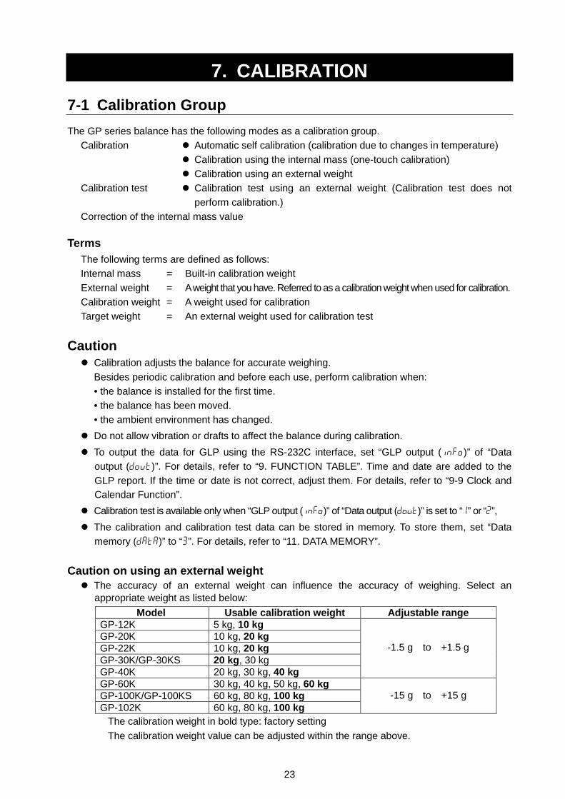
Caution on using an external weight� The accuracy of an external weight can influence the accuracy of weighing. Select an
appropriate weight as listed below:Model Usable calibration weight Adjustable range
GP-12K 5 kg, 10 kgGP-20K 10 kg, 20 kgGP-22K 10 kg, 20 kgGP-30K/GP-30KS 20 kg, 30 kgGP-40K 20 kg, 30 kg, 40 kg
-1.5 g to +1.5 g
GP-60K 30 kg, 40 kg, 50 kg, 60 kgGP-100K/GP-100KS 60 kg, 80 kg, 100 kgGP-102K 60 kg, 80 kg, 100 kg
-15 g to +15 g
The calibration weight in bold type: factory settingThe calibration weight value can be adjusted within the range above.

24
Display� This indicator means “the balance is measuring calibration data”.
Do not allow vibration or drafts to affect the balance while thisindicator is displayed.
7-2 Automatic Self Calibration (Calibration due to changes in temperature)
This function automatically calibrates the balance when the balance detects an ambient temperaturechange. If GLP output is selected in the function table, the balance outputs the calibration report orstores the data in memory. Automatic self calibration functions even if the display is turned off(standby state).
CautionIf something is on the weighing pan, the balance judges that it is in use and does not performautomatic self calibration. To maintain the calibrated state, keep the weighing pan clear whilenot in use.
The displays shown below are related to the automatic self calibration.Indicates that the balance detects a change in ambient temperatureand automatic self calibration will start. If the balance is not used fora few minutes with this indicator blinking, the balance performsautomatic self calibration. The blinking duration depends on theenvironment.
Indicates that the balance is measuring calibration data. Do notallow vibration or drafts to affect the balance while this indicator isdisplayed. After calibration, the balance returns to indicate theprevious display.
NoteThe balance can be used while the indicator blinks. But, it is recommended that to maintainthe accuracy, stop using the balance and confirm that there is nothing on the pan and allowthe balance to perform self calibration.
7-3 Calibration Using the Internal mass (One-Touch Calibration)
This function calibrates the balance using the internal mass. The only operation required is to press
the CAL key.
Operation1 Plug in the AC adapter and warm up the balance for at least 30 minutes with nothing on the
weighing pan.
2 Press the CAL key.
3 The balance displays Calin and performs calibration using the internal mass. Do not allowvibration or drafts to affect the balance.

25
4 The balance displays end after calibration. If the “GLP output (info)” parameter of thefunction table is set to “1” or “2”, the balance displays glp and outputs “Calibration Report”using the RS-232C interface or stores the data in memory. For details on the calibration reportformat, refer to “10-2 GLP Report”.
5 The balance will automatically return to the weighing mode after calibration.
About the internal massThe mass of the internal mass may change due to corrosion or other damage caused by theoperating environment, or due to aging. Check the internal mass periodically. Correct the internalmass value as necessary. For details, refer to “7-6 Correcting the internal mass value”.
To maintain the weighing accuracy, perform the calibration using an external weight periodically,as described below.
7-4 Calibration Using an External WeightThis function calibrates the balance using an external weight.
Operation1 Plug in the AC adapter and warm up the balance for
at least 30 minutes with nothing on the pan.
2 Press and hold the CAL key until Calout isdisplayed, then release the key.
3 The balance displays Cal 0 .
� If you want to change the calibration weight (a listof usable weights is shown on page 23), pressthe SAMPLE key and proceed to step 4.
� If you use the calibration weight value stored inthe balance, proceed to step 5.
4 Specify the calibration weight value as follows:
SAMPLE key To switch the displaycondition to: “All of thesegments blinking”(calibration weight selectionmode) or “The last two digitsblinking” (value adjustmentmode).
RE-ZERO key To select the calibrationweight or adjust the value. Inthe value adjustment mode,-15 digits appear after +15digits.

26
PRINT key To store the new weightvalue. Even if the ACadapter is removed, the datais maintained in non-volatilememory.
CAL key To cancel the operation andreturn to Cal 0 .
NoteDigit, when used for the GP series balance,indicates the smallest displayable weighing value.
5 Confirm that there is nothing on the pan and pressthe PRINT key. The balance measures the zeropoint. Do not allow vibration or drafts to affect thebalance.
The balance displays the calibration weight value.
6 Place the displayed calibration weight on the panand press the PRINT key. The balance measuresthe calibration weight. Do not allow vibration ordrafts to affect the balance.
7 The balance displays end . Remove the weightfrom the pan.
8 If the “GLP output (info)” parameter, of the functiontable, is set to “1” or “2”, the balance displays glpand outputs “Calibration Report” using the RS-232Cinterface or stores the data in memory. For detailson the calibration report format, refer to “10-2 GLPReport”.
9 The balance will automatically return to theweighing mode.
10 Place the calibration weight on the pan and confirmthat the value displayed is within ±2 digits of thespecified value. If it is not within the range, checkthe ambient conditions such as breeze and vibration,also check the weighing pan. Then, repeat steps 1to 10.

27
7-5 Calibration Test Using an External WeightThis function tests the balance weighing accuracy using an external mass and outputs the result. Thisis available only when the “GLP output (info)” parameter is set to “1” or “2”. (Calibration test does notperform calibration.)
Operation1 Connect the AC adapter and warm up the balance
for at least 30 minutes with nothing on the pan.
2 Press and hold the CAL key until CCout isdisplayed, then release the key.
3 The balance displays CC 0 .� If you want to change the target weight (a list of
usable weights is shown on page 23), press theSAMPLE key and proceed to step 4.
� If you use the target weight value stored in thebalance, proceed to step 5.
4 Specify the target weight value as follows:SAMPLE key To switch the display
condition to: “All of thesegments blinking” (targetweight selection mode) or“The last two digits blinking”(value adjustment mode).
RE-ZERO key To select the target weight oradjust the value. In the valueadjustment mode, -15 digitsappear after +15 digits.
PRINT key To store the new weightvalue. Even if the ACadapter is removed, the datais maintained in non-volatilememory.
CAL key To cancel the operation andreturn to CC 0 .
NoteDigit, when used for the GP series balance,indicates the smallest displayable weighing value

28
5 Confirm that there is nothing on the pan and press thePRINT key. The balance measures the zero point anddisplays the measured value. Do not allow vibration ordrafts to affect the balance.The balance displays the target weight value.
6 Place the displayed target weight on the pan and pressthe PRINT key. The balance measures the target weightand displays the measured value. Do not allow vibrationor drafts to affect the balance.
7 The balance displays end . Remove the weight from thepan.
8 The balance displays glp and outputs “CalibrationTest Report” using the RS-232C interface or stores thecalibration test data in memory. For details on thecalibration test report format, refer to “10-2 GLP Report”.
9 The balance will automatically return to the weighingmode.
7-6 Correcting the Internal Mass ValueThe GP series balance can correct the internal mass value within the range shown below. Thisfunction corrects the internal mass value to conform to an external weight. The corrected mass valueis maintained in non-volatile memory even if the AC adapter is removed.The internal mass value is corrected as follows:
Model Correction reference value Correction rangeGP-12K 10 kgGP-20KGP-22K
GP-30K/GP-30KS20 kg
GP-40K 40 kg
-5.0 g to +5.0 g
GP-60K 60 kgGP-100K/GP-100KS
GP-102K 100 kg -50 g to +50 g
Example: Using the GP-20K

29
Operation1 Calibrate the balance using the internal mass. (one-
touch calibration) Then, place an external weight andconfirm the value to be corrected.In the example, the value is to be corrected by 0.6gram in 20 kilograms.
2 Press the ON:OFF key to turn off the display.3 While pressing and holding the PRINT key and the
SAMPLE key, press the ON:OFF key. The balancedisplays p5 .
4 Press the PRINT key. Then the balance displaysthe function switches.
Set the function table switch and internal mass correctionswitch to “1” as shown above using the following keys.
SAMPLE key To select the switch to change thevalue. The selected digit blinks.
RE-ZERO key To change the parameter of theswitch selected.
5 Press the PRINT key to store the new setting. Thebalance returns to the weighing mode.
6 Press and hold the SAMPLE key to enter the functiontable and release the key when ba5fnc is displayed.
7 Press the SAMPLE key several times until C5in isdisplayed, then release the key.
8 Press the PRINT key to enter the procedure for correctingthe internal mass value.
9 Correct the internal mass value using the following keys.
RE-ZERO key To select the value.(-50 digits appear after +50 digits.)
PRINT key To store the new value and display thenext menu item of the function table.
CAL key To cancel the correction anddisplay the next menu item of thefunction table.
10 Press the CAL key. The balance returns to the weighing mode.11 Press the CAL key to calibrate the balance using the internal mass.12 Place the external weight on the pan and confirm that the correction has been performed
properly. In this example, confirm that the value displayed is within ±2 digits of the correctionreference value or 20 kilograms. If the value is not within ±2 digits of the correction value,repeat the above procedure to correct it.

30
8. FUNCTION SWITCH AND INITIALIZATION8-1 Permit or InhibitThe balance stores parameters that must not be changed unintentionally (e.g. Calibration data foraccurate weighing, Data for adapting to the operating environment, Control data for the RS-232Cinterface). There are five switches for the purpose of protecting these parameters. Each switch canselect either “permit” or “inhibit”. The “inhibit” protects parameters against unintentional operations.
Switches
Operation1 Press the ON:OFF key to turn off the display.
2 While pressing and holding the PRINT key and the SAMPLE key, press the ON:OFF key. Thebalance displays p5 .
3 Press the PRINT key. Then the balance displays the function switches.
4 Set the switches using the following keys.
SAMPLE key To select the switch to change the parameter. The selected switch blinks.
RE-ZERO key To change the parameter of the switch selected.
0:To inhibit changes./ Can not be used.
1:To permit changes./ Can be used.
PRINT key To store the new parameter and return to the weighing mode.
CAL key To cancel the operation and return to the weighing mode.

31
8-2 Initializing the BalanceThis function returns the following parameters to factory settings.
� Calibration data� Function table� The sample unit mass value (counting mode), 100% reference mass value (percent mode)� The data that is stored in the balance using the data memory function� External calibration weight and target weight value� Function switch settings� Liquid density and temperature in the density mode
NoteBe sure to calibrate the balance after initialization.
Operation1 Press the ON:OFF key to turn off the display.
2 While pressing and holding the PRINT key and theSAMPLE key, press the ON:OFF key. The balancedisplays p5 .
3 Press the SAMPLE key to display Clr .
4 Press the PRINT key.To cancel this operation, press the CAL key.
5 Press the RE-ZERO key.
6 Press the PRINT key to initialize the balance.
The balance will automatically return to the weighingmode.

32
9. FUNCTION TABLEThe function table reads or rewrites the parameters that are stored in the balance. These parametersare maintained in non-volatile memory, even if the AC adapter is removed.
9-1 Structure and Sequence of the Function TableThe function table menu consists of two layers. The first layer is the “Class” and the second layer isthe “Item”. Each item stores a parameter.
ExampleThis example sets “Stores weighing data” for “Data memory” and “1 minute” for “Interval time”.
9-2 Display and KeysDisplay/Key Description
The symbol “ ” indicates that the parameter displayed is in effect.
When pressed and held in the weighing mode, enters the function table mode.Selects the class or item in the function table mode.Changes the parameter.
When a class is displayed, moves to an item in the class.When an item is displayed, stores the new parameter and displays the next class.When an item is displayed, cancels the new parameter and displays the next class.When a class is displayed, exits the function table mode and returns to theweighing mode.

33
9-3 Details of the Function Table

34

35
CautionThe balance may not transmit the data completely at the specified refresh rate, depending onthe baud rate or data added to the weighing data such as time, date and ID number.

36
9-4 Description of the Class “Environment, Display”Condition ( CondCondCondCond )
Cond 0 This parameter is for sensitive response to the fluctuation of a weight value.Used for powder target weighing, weighing a very light sample or when quickresponse weighing is required.After setting, the balance displays FAST.
Cond 2 This parameter is for stable weighing with slow response. Used to prevent aweight value from drifting due to vibration or drafts.After setting, the balance displays SLOW.
NotesIn automatic response adjustment, the response rate is selectedautomatically.With “Hold function (HoldHoldHoldHold)” set to “ON (1111)”, this item is used to set theaveraging time.
Stability band width ( 5t-b5t-b5t-b5t-b )This item controls the width to regard a weight value as a stable value. When the fluctuation persecond is less than the parameter, the balance displays the stabilization indicator and outputs orstores the data. The parameter influences the “Auto print mode”
5t-b 0 This parameter is for sensitive response of the stabilization indicator. Usedfor exact weighing.
5t-b 2 This parameter ignores slight fluctuation of a weight value. Used to prevent aweight value from drifting due to vibration or drafts.
NoteWith “Hold function (HoldHoldHoldHold)” set to “ON (1111)”, this item is used to set thestabilization range.
Hold function ( HoldHoldHoldHold ) (Animal weighing mode)This function is used to weigh a moving object such as an animal.When the weighing data is over the weighing range from zero and the display fluctuation is within thestabilization range for a fixed period of averaging time, the processing indicator illuminates and thebalance displays the average weight of the animal. When the animal is removed from the weighingpan, the display returns to zero automatically.This function is available only when the hold function parameter is set to “1” (the animal modeindicator ANIMAL illuminates) and any weighing unit other than the counting mode is selected.
The stabilization range and averaging time are set in “Condition (Cond)” and “Stability band width (5t-b)”.Weighing range Averaging time Stabilization range
GP-12K/20K/22K Cond 0 5t-b 0GP-30K/30KS/40K 20 g
Cond 1 5t-b 1GP-60K/100K/100KS Cond 2
2 seconds Faster4 seconds |8 seconds More accurate 5t-b 2
Small|
BigGP-102K
50 g

37
Zero tracking ( trc trc trc trc )This function tracks zero point drift caused by changes in the environment and stabilizes the zeropoint. When the weighing data is only a few digits, turn the function off for accurate weighing.
NoteDigit, when used for the GP series balance, indicates the smallest displayable weighing value.
trc 0 The tracking function is not used. Used for weighing a very light sample.
trc 1 The tracking function is used.
Display refresh rate ( 5pd5pd5pd5pd )Period to refresh the display. This parameter influences “Baud rate”, “Data output pause” and “Stream mode”.
NoteThis item is selected automatically in the automatic response adjustment.
Decimal point ( pntpntpntpnt )The decimal point format can be selected.
Auto display-ON ( p-onp-onp-onp-on )When the AC adapter is plugged in, the display is automatically turned on without the ON:OFF keyoperation, to display the weighing mode. Used when the balance is built into an automated system.30-minute warm up is necessary for accurate weighing.
Auto display-OFF ( poffpoffpoffpoff )When the AC adapter is connected and no operation is performed (inactivity state) for 10 minutes, thedisplay is automatically turned off and the standby indicator illuminates.
Capacity indicator ( g5ig5ig5ig5i )In the weighing mode, the indicator displays the weighing data relative to the weighing capacity inpercentage. (Zero = 0%, maximum capacity = 100%)When the “Data memory (data)” parameter is set to “1” (to store unit mass in the counting mode), “2”(to store the weighing data), “4” (to store comparator settings) or “5” (to store tare value), the indicatordisplays the information stored in memory, such as the amount of memory data or data number.
Accumulation function ( addaddaddadd )The accumulation function adds the weighing data, displays and outputs the total value. For details,refer to “5-4 Accumulation Function.”
Display at start ( rng rng rng rng )When the weighing accuracy is not so strict, the smallest displayable weighing value can be turned offwithout any key operation at weighing start. Useful when the balance is built into an automated system.

38
9-5 Description of the Item “Data output mode”The parameter setting of “Data output mode (prt)” applies to the performance when the “Datamemory (data)” parameter is set to “2” (to store the weighing data) and when the data is transmittedusing the RS-232C interface.
Key modeWhen the PRINT key is pressed with the stabilization indictor turned on, the balance outputs or storesthe weighing data and the display blinks one time.
Required setting dout prt 0 Key mode
Auto print modes A and BWhen the displayed value is stable and the conditions of “Auto print polarity”, “Auto print difference”and reference value are met, the balance outputs or stores the weighing data.When the PRINT key is pressed with the stabilization indictor turned on, the balance outputs or storesthe data and the display blinks one time.
Mode A: Required setting dout prt 1 Auto print mode A (reference = zero)dout ap-p Auto print polaritydout ap-b Auto print difference
Example “For weighing each time a sample is placed and removed,with “ar-d” set to “1” (to adjust zero after the data is output).”
Mode B: Required setting dout prt 2 Auto print mode B (reference =last stable value)
dout ap-p Auto print polaritydout ap-b Auto print difference
Example “For weighing while a sample is added.”
Stream modeThe balance outputs the weighing data continuously regardless of the display condition. The displaydoes not blink in this mode. This mode is not available and the interval memory mode is used whenthe “Data memory (data)” parameter is set to “2” (to store the weighing data).
Required setting dout prt 3 Stream modedout data 0 Data memory function is not used.ba5fnc 5pd Display refresh rate5if bp5 Baud rate
Example “For monitoring data on a computer”
CautionThe balance may not transmit the data completely at the specified refresh rate, depending onthe baud rate or data added to the weighing data such as time, date and ID number.

39
Interval memory modeThe weighing data is periodically stored in memory.
Required setting dout prt 3 Interval memory modedout data 2 Data memory function is used.
Stores weighing data.dout int Interval time
Optional setting dout 5-td1, 2, or 3 Adds the time and date.
Example “For periodical weighing without a computer command and to outputall of the data, to a computer, at one time”
9-6 Description of the Item “Data format”A&D standard format 5if type 0This format is used when the peripheral equipment can receive the A&D format. If an AD-8121 isused, set the printer to MODE 1 or 2.
� This format consists of fifteen characters excluding the terminator.
� A header of two characters indicates the balance condition.
� The polarity sign is placed before the data with the leading zeros. If the data is zero, the plussign is used.
� The unit, consisting of three characters, follows the data.
DP (Dump print) format 5if type 1This format is used when the peripheral equipment can not receive the A&D format. If an AD-8121 isused, set the printer to MODE 3.
� This format consists of sixteen characters excluding the terminator.
� A header of two characters indicates the balance condition. No overload header is used.
� The polarity sign is placed before the data, with spaces in place of leading zeros, if the data isnot zero or overloaded.
� The unit, consisting of three characters, follows the data.

40
KF format 5if type 2This is the Karl-Fischer moisture meter format and is used when the peripheral equipment can onlycommunicate using this format.
� This format consists of fourteen characters excluding the terminator.
� This format has no header characters.
� The polarity sign is placed before the data, with spaces in place of leading zeros, if the data isnot zero or overloaded.
� This format outputs the unit only for a stable value.
MT format 5if type 35if type 35if type 35if type 3� A header of two characters indicates the balance condition.
� The polarity sign is used only for negative data.
� The weighing data uses spaces in place of the leading zeros.
� The character length of this format changes dependent upon the unit
NU (numerical) format 5if type 45if type 45if type 45if type 4This format outputs only numerical data.
� This format consists of nine characters excluding the terminator.
� The polarity sign is placed before the data with the leading zeros. If the data is zero, the plussign is used.
CSV format 5if type 55if type 55if type 55if type 5� Separates the data of A&D standard format and the unit by a comma ( , ).
� Outputs the unit even when the data is overloaded.
� When ID number, data number, time and date are added, outputs ID number, data number,date, time and weighing data in this order and separates each item by a comma and treats allthe items as one group of data.

41
9-7 Description of the Data Format Added to the Weighing Data
ID number dout 5-id 1The number to identify a specific balance.
� This format consists of seven characters excluding the terminator.
Data number dout d-no 1dout d-no 1dout d-no 1dout d-no 1This format outputs the data number just before the data is transmitted using the RS-232C interface.
� This format consists of six characters excluding the terminator.
� When CSV format (5if type 5) is selected, the period ( . ) is replaced with a comma ( , ).
Date dout 5-td 2 or 3� The date output order can be changed in “Clock (Cl adj)”. Outputs the year in four-digit format.
Time dout 5-td 1 or 3� Outputs time in 24-hour format.
Tare value� When the tare value in memory is recalled, the tare value is output before the weighing data.
Comparison results� By setting “Comparison results (Cp-r)” of the function table to “1”, the comparison results can be
added to the data output using the RS-232C serial interface. Use A&D standard format (type 0).The AD-8121 printer can not be used.The comparison results are added after the header in A&D standard format as below.
NoteWhen the data described above is added to the weighing data, the output is in the followingorder: ID number, Data number, Date, Time and Weighing data.

42
9-8 Data Format Examples

43
NoteWhen “Pound Ounce” is selected, the data is output with the unit of ounce (oz).

44
9-9 Clock and Calendar FunctionThe balance is equipped with a clock and calendar function. When the “GLP output (info)”parameter is set to “1” or “2” and the “Time/Date output (5-td)” parameter is set to “1”, “2” or “3”, thetime and date are added to the output data. Set or confirm the time and date as follows:
Operation1 Press and hold the SAMPLE key until ba5fnc of the
function table is displayed, then release the key.
2 Press the SAMPLE key several times to display Cl adj .
3 Press the PRINT key. The balance enters the mode toconfirm or set the time and date.
Confirming the time4 The current time is displayed with all the digits blinking.
� When the time is correct and the date does notneed to be confirmed, press the CAL key andproceed to step 8.
� When the time is correct and the date is to beconfirmed, press the SAMPLE key and proceed tostep 6.
� When the time is not correct and is to be changed,press the RE-ZERO key and proceed to step 5.
Setting the time (with part of the digits blinking)5 Set the time in 24-hour format using the following keys.
SAMPLE key To select the digits to change thevalue. The selected digits blink.
RE-ZERO key To increase the value by one.MODE key To decrease the value by one.PRINT key To store the new setting, display
end and go to step 6.CAL key To cancel the new setting and
go to step 6.

45
Confirming the date6 The current date is displayed with all the digits blinking.
� To change the display order of year (y), month (n)and day (d), press the MODE key. The date isoutput in the order as specified.
� When the date is correct and the operation is to befinished, press the CAL key and proceed to step 8.
� When the time is to be confirmed again, press theSAMPLE key and go back to step 4.
� When the date is not correct and is to be changed,press the RE-ZERO key and proceed to step 7.
NoteThe year is expressed using a two-digit format. Forexample, the year 2000 is expressed as “00”.
Setting the date (with part of the digits blinking)7 Set the date using the following keys.
SAMPLE key To select the digits to change thevalue. The selected digits blink.
RE-ZERO key To increase the value by one.
MODE key To decrease the value by one.
PRINT key To store the new setting, displayend and go to step 8.
CAL key To cancel the new setting andgo to step 8.
Quitting the operation8 The balance displays the next menu item of the
function table. Press the CAL key to exit the clock andcalendar function and return to the weighing mode.
NotesDo not enter invalid values such as a non-existing date when setting the time and date.When the clock backup battery has been depleted, the balance displays rtc pf rtc pf rtc pf rtc pf . Underthis condition, press any key and set the time and date. The dead battery only affects theclock and calendar function. Even so, the function works normally as long as the ACadapter is connected to the balance.

46
9-10 Comparator FunctionThe results of the comparison are indicated by HI OK LO on the display.
Operating conditions: � No comparison� Comparison when the weighing data is stable or overloaded, excluding “near zero”� Comparison when the weighing data is stable or overloaded, including “near zero”� Continuous comparison, excluding “near zero”� Continuous comparison, including “near zero”
To compare, use: � Upper limit value and lower limit value� Reference value and tolerance value
Input method: � Digital input� Weighing input
For a description of “Comparator mode (Cp fnc)”, refer to “9-3 Details of the Function Table”.
Setting example 1(Comparison when the weighing data is stable or overloaded, excluding “near zero”, upper limit and lower limit)
Selecting a comparator mode1 Press and hold the SAMPLE key until ba5fnc of the function table is displayed, then release the key.
2 Press the SAMPLE key several times to display Cp fnc .
3 Press the PRINT key.
4 Press the RE-ZERO key several times to display Cp 1 .
5 Press the SAMPLE key to display Cp in .
6 Press the RE-ZERO key several times to display Cp in 0 .
7 Press the PRINT key to store the selected mode.
Entering the upper and lower limit values
8 With Cp Hi displayed, press the PRINT key. The current setting of the upper limit value isdisplayed with all of the digits blinking.� When the current setting is not to be changed, press the PRINT or CAL key to proceed to step 9.� When the current setting is to be changed, press the RE-ZERO key. The balance is now in
the digital input mode. To use the weighing input mode, press and hold the MODE key.
Digital input modeChange the setting using the following keys.
SAMPLE key To select the digit to change the value.RE-ZERO key To change the value of the digit selected.MODE key To switch the polarity.PRINT key To store the new setting and go to step 9.CAL key To cancel the new setting and go to step 9.

47
Weighing input modePress the RE-ZERO key. The balance displays 0.0 g. Place a sample, with a mass thatcorresponds to the upper limit value, on the pan. Press the PRINT key to store the upper limit
value. Remove the sample. The balance displays Cp lo .
9 With Cp lo displayed, press the PRINT key. The current setting of the lower limit value isdisplayed with all of the digits blinking.
� When the current setting is not to be changed, press the PRINT or CAL key to proceed to step 10.� When the current setting is to be changed, press the RE-ZERO key. The balance is now in
the digital input mode. To use the weighing input mode, press and hold the MODE key.Enter the lower limit value in the same way as described in step 8. Then, go to step 10.
10 Press the CAL key to exit the comparator function and return to the weighing mode.
Setting example 2(Continuous comparison, including “near zero”, reference value and tolerance value)
Selecting a comparator mode
1 Press and hold the SAMPLE key until ba5fnc of the function table is displayed, then release the key.
2 Press the SAMPLE key several times to display Cp fnc .
3 Press the PRINT key.
4 Press the RE-ZERO key several times to display Cp 4 .
5 Press the SAMPLE key to display Cp in .
6 Press the RE-ZERO key several times to display Cp in 1 .
7 Press the PRINT key to store the selected mode.
Entering the reference and tolerance values8 With Cp ref displayed, press the PRINT key. The current setting of the reference value is
displayed with all the digits blinking.� When the current setting is not to be changed, press the PRINT or CAL key to proceed to step 9.� When the current setting is to be changed, press the RE-ZERO key. The balance is now in
the digital input mode. To use the weighing input mode, press and hold the MODE key.
Digital input modeChange the setting using the following keys.
SAMPLE key To select the digit to change the value.RE-ZERO key To change the value of the digit selected.MODE key To switch the polarity.PRINT key To store the new setting and go to step 9.CAL key To cancel the new setting and go to step 9.
Weighing input modePress the RE-ZERO key. The balance displays 0.0 g. Place a sample, with a mass thatcorresponds to the reference value, on the pan. Press the PRINT key to store the referencevalue. Remove the sample and go to step 9.

48
9 With Cp lnt displayed, press the PRINT key. The current setting of the tolerance value isdisplayed with all the digits blinking.
� When the current setting is not to be changed, press the PRINT or CAL key to proceed to step10.� When the current setting is to be changed, press the RE-ZERO key. The balance is now in
the digital input mode. Change the setting using the following keys.
SAMPLE key To select the digit to change the value.RE-ZERO key To change the value of the digit selected.PRINT key To store the new setting and go to step 10.CAL key To cancel the new setting and go to step 10.Notes: Enter the tolerance value in percentage, with the reference value as 100%.
Only the digital input mode is available for setting the tolerance value.The MODE key is not used to set the tolerance value.
10 Press the CAL key to exit the comparator function and return to the weighing mode.
NotesWhen Pound/Ounce is selected as a weighing unit, enter the values in ounces for comparison.In the density mode, comparison is performed to the density obtained.
9-11 Adding the Comparison ResultsBy setting “Comparison results (Cp-r)” of the function table to “1”, the comparison results can be
added to the data output using the RS-232C serial interface. Use A&D standard format (type 0). TheAD-8121 printer can not be used.
The comparison results are added after the header in A&D standard format as below.
9-12 Main Display Comparison FunctionThe main display comparison function displays the comparison results in a magnified way, on the
main portion of the display in place of the weight value.
Selecting a unit1 Press the MODE key to select a unit to be used for comparison.
NoteWhile the main display comparison function is in use, unit selection using the MODE key is not available.

49
Setting the function table2 Press and hold the SAMPLE key until ba5fnc of the function table is displayed, then release the key.
3 Press the SAMPLE key several times to display Cp fnc .
4 Press the PRINT key.
5 Press the SAMPLE key several times to display Cp-b 0 .
6 Press the RE-ZERO key to display Cp-b 1 .
NoteTo disable the main display comparison funciton, set the “Main display comparison (Cp-bCp-bCp-bCp-b)”parameter to “0000”.
7 Press the PRINT key to store the setting.
8 Press the CAL key to return to the weighing mode.
Setting the comparator valuesSetting the comparator values as described in theprevious section.Setting example (Cp 3=Continuous comparison,excluding “near zero”)
Using the main display comparison function1 Press the RE-ZERO key to set the display to zero.
2 Place a sample on the pan. The balanceperforms a comparison using the specifiedcomparison values and displays thecomparison results, HI, OK or LO.
3 Each time the MODE key is pressed, thebalance switches between the standarddisplay and the main display comparison.Note that “g0” appears for OK.
NotesWhile the main display comparison functionis in use, the processing indicatorilluminates as shown in the illustration.If the comparison is not performed, forexample, because the weight value is nearzero or unstable, the balance displays theweight value even when the main displaycomparison function is used.Even while the main display comparisonfunction is in use, the balance re-zeroingand data output is possible.Only the unit selected before this function can be used.While the main display comparison function is in use, the data memory function is notavailable.

50
10. ID NUMBER AND GLP REPORT� The ID number is used to identify the balance when Good Laboratory Practice (GLP) is used.
� The ID number is maintained in non-volatile memory even if the AC adapter is removed.
� The GLP output format is selected at “GLP output (info)” of the function table and can beoutput to a personal computer or printer using the RS-232C serial interface.
� The GLP output format includes the balance manufacturer, model, serial number, ID number,date, time and space for signature for weighing data, the weight used and results for calibrationor calibration test data.
� The balance can output the following reports for GLP.
“Calibration report” of the calibration, using the internal mass (Calibration due to changes intemperature and one-touch calibration.)
“Calibration report” of the calibration, using an external weight.
“Calibration test report” of the calibration test, using an external weight.
“Title block” and “End block” for the weighing data.
� Calibration and calibration test data can be stored in memory to output several reports at thesame time. Refer to “11. DATA MEMORY” for details.
� For details on confirming and setting the time and date, refer to “9-9 Clock and CalendarFunction”.
10-1 Setting the ID Number1 Press and hold the SAMPLE key until ba5fnc of the function table is displayed, then release
the key.
2 Press the SAMPLE key several times to display id .
3 Press the PRINT key. Set the ID number using the following keys.
RE-ZERO key To set the character of the digit selected. Refer to the display characterset shown below.
SAMPLE key To select the digit to change the value.
PRINT key To store the new ID number and display ba5fnc.
CAL key To cancel the new ID number and display ba5fnc.
4 With ba5fnc displayed, press the CAL key to return to the weighing mode.
Display character set

51
10-2 GLP ReportSet the following parameters to output the report.
� To print the report, set the “GLP output (info)” parameter to “1” and use MODE 3 of the AD-8121. For details on using the printer, refer to “15-1 Connection to the AD-8121 Printer”.
� To output the report to a personal computer using the RS-232C interface, set the “GLP output(info)” parameter to “2”.
� If the time and date are not correct, set the correct time and date in “Clock (Cl adj)” of thefunction table.
NoteFor operational details about calibration and calibration test, refer to “7. CALIBRATION”.
Calibration report using the internal mass
When the setting is “info 1”: When the setting is “info 2”:

52
Calibration report using an external weightWhen the setting is “info 1”: When the setting is “info 2”:
Calibration test report using an external weight(Calibration test does not perform calibration.)
When the setting is “info 1”: When the setting is “info 2”:

53
Title block and end blockWhen weight values are recorded as GLP data, a “Title block” is inserted at the beginning and an“End block” is inserted at the end of a group of weight values in the GLP report.
NoteTo output the report to an AD-8121 , use MODE 3 of the AD-8121.
CautionIf the data memory function is used, the “Title block” and “End block” can not be output.
Operation1 With the weighing data displayed, press and hold the PRINT key, then release the key. S5tart
is displayed. The “Title block” is output.
2 The weighing data is output according to the parameter setting of the data output mode.
3 Press and hold the PRINT key until recend is displayed, then release the key. The “Endblock” is output.
When the setting is “info 1”: When the setting is “info 2”:

54
11. DATA MEMORYData memory is a function to store weighing data, calibration data and unit mass in memory. Of thedata in memory, the balance can only display the weighing data. The weighing data and calibrationdata in memory are available for outputting at one time to a printer or personal computer.
One of the following data sets can be stored:
� Weighing data (Up to 200 sets. 100 sets when the time and date are added.)
� Calibration and calibration test data (latest 50 sets)
� Unit mass in the counting mode (Up to 50 sets)
� Comparator settings (the upper and lower limit values only, up to 20 sets)
� Tare value (Up to 20 sets)
11-1 Notes on Using Data MemoryTo use the memory function, set the “Data memory (data)” parameter of the function table. In addition,for weighing data, set the “Time/Date output (5-td)” parameter. For details on setting the datamemory, refer to “9. FUNCTION TABLE”.
For weighing data, the data contents to be stored and the storage capacity depend on the “Time/Dateoutput (5-td)” parameter setting.
Releasing “ClrClrClrClr”If a different type of data exists in memory when the data is stored, “Clr” appears blinking in theupper left of the display. For example, you want to store weighing data but calibration data or unitmass data remains in memory.
Under such a condition, before storing data, delete the data in memory as follows:
1 Press and hold the PRINT key until SClr no with “no” blinking is displayed, then release thekey.
2 Press the RE-ZERO key to display SClr go with “go” blinking.
The type of data stored in memory appears in the upper left of the display as shown below:
Unit mass in the counting mode pC
Weighing data without time and date -d-
Weighing data with time and date d-t
Calibration or calibration test data Hi5
Comparator settings Cp
Tare value tr
3 Press the PRINT key to delete all the data in memory.
4 The balance displays end and returns to the weighing mode.

55
11-2 Memory for Weighing Data� The data memory function can store 200 sets of weighing data (100 set if time and date are
added). Even if the AC adapter is removed, the data is maintained in non-volatile memory.
� It is not necessary that the printer or computer be continually connected to the balance,because the balance stores the weighing data in memory.
� The data in memory is available to be displayed on the balance for confirmation, or to outputseveral sets of data at one time to a printer or personal computer. In the function setting, whatdata is to be added to the output data (ID number, data number, time and date) can beselected.
Storing the weighing data
NoteIf “ClrClrClrClr” appears blinking in the upper left of the display, delete the data in memory.
1 Set the “Data memory (data)” parameter to “2”.
2 Set the “Time/Date output (5-td)” parameter as necessary.
3 The storing operation depends on the “Data output mode (prt)” parameter setting. Four typesof operating modes are available to store data.
Key mode When the PRINT key is pressed and the displayed value isstable, the balance stores the weighing data.
Auto print modes A and B When the displayed value is stable and the conditions of “Autoprint polarity”, “Auto print difference” and reference value aremet, the balance stores the weighing data.
Interval memory mode Weighing data is stored at an interval specified in “Interval time(int)”. Press the PRINT key to start and stop this mode.
Caution� When weighing data is being stored in memory, the data can not be output to a personal
computer using the RS-232C interface.
� “fUl” indicates that memory is full or the memory capacity has been reached. More data cannot be stored unless the memory data is deleted.
� Automatic self calibration can not be used while the interval memory mode is active.

56
� The following commands can not be used during data storage.
Q Query command for weighing data.
S Query command for stable weighing data.
SI Query command for weighing data.
SIR Query command for continuous weighing data.
Setting the function tableParameter settings for each output mode are as follows:
Item
Mode
Data outputmode
Auto printpolarity,difference
Data memoryfunction
Intervaltime
Key mode prt 0 Not used data 2Auto print mode A prt 1 data 2Auto print mode B prt 2
ap-a 0-2ap-b 0-2 data 2
Not used
Interval memory mode prt 3 Not used data 2 int 0-8
Set each item, depending on the situation, as follows:No d-no 0 No 5-td 0Data numberYes d-no 1 Time only 5-td 1No 5-id 0 Date only 5-td 2ID numberYes 5-id 1
Time and date
Both 5-td 3
With 5-td 1, 5-td 2 or 5-td 3 selected, the amount of data to be stored is 100 sets.
Enabling the data memory function1 Press and hold the SAMPLE key until ba5fnc is displayed, then release the key.
2 Press the SAMPLE key several times to display dout .
3 Press the PRINT key.
4 Press the SAMPLE key three times to display data 0 .
5 Press the RE-ZERO key to display data 2 .
6 Press the PRINT key to store the setting.
7 Press the CAL key to return to the weighing mode.

57
Recalling the memory dataConfirm that the “Data memory (data)” parameter is set to “2”.
1 Press and hold the PRINT key until reCall is displayed, then release the key.
2 Press the PRINT key to enter the memory recall mode. The type of data appears in the upperleft of the display as shown to the right:
Recall the data in memory using the following keys
RE-ZERO key To proceed to the next data set.
MODE key To go back to the previous data set.
PRINT key To transmit the current data usingthe RS-232C interface.
With SAMPLE held down, press the CAL keyTo delete the data currently displayed.
Note: Deleting the data will not increase the number of data that can be stored.
CAL key To exit the memory recall mode.
3 Press the CAL key to return to the weighing mode.
Transmitting all memory data at one timeConfirm that the “Serial interface (5if)” parameters are set properly. For details, refer to “9.FUNCTION TABLE” and “15. CONNECTION TO PERIPHERAL EQUIPMENT”.
1 Press and hold the PRINT key until reCall is displayed,then release the key.
2 Press the SAMPLE key to display out .
3 Press the PRINT key to display Sout no with “no” blinking.
5 Press the RE-ZERO key to display out go with “go”blinking.
6 Press the PRINT key to transmit all data using the RS-232Cinterface.
7 The balance displays Clear when all data is transmitted.Press the CAL key to return to the weighing mode.
Deleting all memory data at one time1 Press and hold the PRINT key until reCall is displayed, then release the key.
2 Press the SAMPLE key several times to display Clear .
3 Press the PRINT key to display SClr no with “no” blinking.
4 Press the RE-ZERO key to display SClr go with “go” blinking.
5 Press the PRINT key to delete all data
6 The balance displays end , then reCall when all data is deleted.
7 Press the CAL key to return to the weighing mode.

58
11-3 Memory for Calibration and Calibration Test Data� Calibration data (when and how it is performed) and calibration test data can be stored in memory.
� All the data in memory is available to be output at one time to a printer or personal computer.
� Up to 50 data sets of the latest calibration or calibration test can be stored. When the memorycapacity has been reached, “fUl” illuminates in the upper left of the display as shown below.
Storing the calibration and calibration test dataNoteIf “ClrClrClrClr” appears blinking in the upper left of the display, delete the data in memory.
Store the calibration and calibration test data as follows:1 Set the “Data memory (data)” parameter to “3”.
2 Set the “GLP output (info)” parameter to “1” or “2”.
3 With the settings above, each time calibration or calibration test is performed, the data is storedautomatically.
Transmitting the memory dataConfirm that the “Serial interface (5if)” parameters are set properly. For details, refer to “9.FUNCTION TABLE” and “15. CONNECTION TO PERIPHERAL EQUIPMENT” and also confirm thatthe “Data memory (data)” parameter is set to “3”.
1 Press and hold the PRINT key until out is displayed, thenrelease the key.
2 Press the PRINT key to display Sout no with “no” blinking.
3 Press the RE-ZERO key to display out go with “go” blinking.
4 Press the PRINT key to transmit all memory data using theRS-232C interface.
5 The balance displays Clear when all memory data is output. Press the CAL key to returnto the weighing mode.
Deleting the memory data1 Press and hold the PRINT key until out is displayed, then
release the key.
2 Press the SAMPLE key to display Clear .
3 Press the PRINT key to display SClr no with “no” blinking.
4 Press the RE-ZERO key to display SClr go with “go” blinking.
5 Press the PRINT key to delete all data
6 The balance displays out when all the data has been deleted. Press the CAL key to returnto the weighing mode.

59
11-4 Memory for Unit Mass in the Counting Mode� The data memory function can store 50 sets of unit mass for the counting mode. Even if the AC
adapter is removed, the data is maintained in non-volatile memory. Among the 50 sets, “p01” isthe memory function for the standard counting mode.
� The unit mass in memory can be recalled and used for weighing.� The unit mass in memory can be recalled and changed.
NoteThe recalled unit mass can be changed, using the weighing input mode or the digital inputmode. The weighing input mode uses the specified number of samples to store the unit mass.The digital input mode enters the unit mass using the keys.
Storing the unit mass
To store a new unit mass: Recall the stored unit mass to be changed (“Pp01” to “p50”). Then, change therecalled unit mass using the weighing input mode or the digital input mode, and store the new unit mass.
1 Set the “Data memory ( data )” parameter to “1”.
2 Press the MODE key to select pcs (counting mode).If “Clr” appears blinking in the upper left of the display, delete the data in memory.
NoteIf the counting mode can not be selected, refer to “4. WEIGHING UNITS”.
3 Press and hold the PRINT key until the balance enters the sample unit mass confirmationmode. The unit mass last selected is displayed as shown below.
All the digits blinking
4 Select the unit mass number to be used, using the following keys.
RE-ZERO key To increase the unit mass number by one.MODE key To decrease the unit mass by one.
5 To change the selected unit mass:
To use the weighing input mode, press the SAMPLE key to enter the weighing input mode.Go to “Weighing input mode” on the next page.
To use the digital input mode, press the SAMPLE key, then press and hold the MODE key toenter the digital input mode. Go to “Digital input mode” on the next page.
NotesACAI can not be performed directly on the recalled unit mass.Using the “UN:mm” command, the unit mass can be recalled. (mm indicates a two-digitnumerical value 01-50, which corresponds to P01-P50.) The unit mass recalled can be outputusing the “?UW” command and can be changed using the “UW:” command.

60
Weighing input modeIn the weighing input mode, the specified number of samples is placed on the pan to store the unitmass. Re-storing the unit mass or performing Automatic Counting Accuracy Improvement (ACAI) onthe re-stored unit mass is possible. Follow the procedure described in “5-2. Counting Mode (PCS)”.
Use the following keys to store a unit mass in weighing input mode.RE-ZERO key To set the display to zero. 10 - pcs → 10 0 pcsSAMPLE key To change the number of samples to be stored. 10 0 pcs → 25 0 pcsPRINT key Press, after a sample is placed, to store the unit mass.CAL key To return to the unit mass confirmation mode (step 3 in “Recalling the
unit mass”).MODE key Press and hold to go to the digital input mode.
Digital input modeTo use this mode, the sample unit mass must be known beforehand. In the digital input mode, the unit
mass value is entered digitally using the keys.
The display in the digital input mode is shown to the right.
The digit to be changed blinks.NoteACAI can not be used on the unit mass stored using the digital input mode.
Use the following keys to store a unit mass in digital input mode.SAMPLE key To select the digit to be changed.RE-ZERO key To change the value of the
selected digit.MODE key To change the decimal point position.PRINT key To store the unit mass.CAL key To return to the unit mass
confirmation mode (step 3 in“Recalling the unit mass”).
MODE key Press and hold to go to theweighing input mode.
NoteIf the set unit mass is out of the setting range, “error 2error 2error 2error 2” is displayed. For details about theminimum unit mass, refer to “19. SPECIFICATIONS”.
Recalling the unit mass1 Follow steps1 through 3 in “Storing the unit mass” on
the previous page, to enter the sample unit massconfirmation mode.
2 Select the unit mass number to be used, using thefollowing keys.
RE-ZERO key To increase the unit massnumber by one.
MODE key To decrease the unit mass by one.
3 Press the PRINT key to confirm the selection and to return to the weighing mode.To cancel the selection and return to the weighing mode, press the CAL key.

61
11-5 Memory for Comparator Settings� The data memory function can store 20 sets of upper and lower limit values for the comparator mode.
The reference value or tolerance value for the comparator mode can not be stored in memory.� The upper and lower limit values in memory can be recalled easily using the MODE key and
used for weighing.� The upper and lower limit values in memory can be recalled and changed.
NoteThe recalled upper and lower limit values can be changed, using the digital input mode or theweighing input mode. The digital input mode enters the upper and lower limit values using thekeys. The weighing input mode uses a sample to store the upper and lower limit values.
Storing the upper and lower limit valuesTo store new upper and lower limit values: Recall the stored upper and lower limit values to bechanged (“C01” to “C20”). Then, change the recalled upper and lower limit values using the digitalinput mode or the weighing input mode, and store the new value.
1 Press the MODE key to select a unit to be used for storage.
NoteWhile the data memory function is in use, unit selection using the MODE key is not available.
2 Set the “Data memory (data)” parameter to “4”.If “Clr” appears blinking in the upper left of the display, delete the data in memory as describedin “11-1 Notes on Using Data Memory”.
3 Press and hold the PRINT key until the balance enters the upper and lower limit valuesconfirmation mode. The upper limit value last selected is displayed as shown below.
All the digits blinking
4 Select the comparator number to be used, using the following keys.
RE-ZERO key To increase the comparator number by one.MODE key To decrease the comparator number by one.
Each time the RE-ZERO key or MODE key is pressed, the displayed valuechanges as follows: .... ↔ C03 HI ↔ C03 LO ↔ C04 HI ↔ C04 LO ↔ ....
5 To change the selected upper and lower limit values:
To use the digital input mode, press the SAMPLE key to enter the digital input mode. Go to“Digital input mode” on the next page.
To use the weighing input mode, press the SAMPLE key, then press and hold the MODE keyto enter the weighing input mode. Go to “Weighing input mode” on the next page.
NoteUsing the “CN:mm” command, the upper and lower limit values can be recalled. (mmindicates a two-digit numerical value 01-20, which corresponds to C01-C20.) The upper andlower limit values recalled can be output using the “?HI” command or “?LO” command andcan be changed using the “HI:” command or “LO:” command.

62
Digital input modeIn the digital input mode, the upper and lower limit values are entered digitally using the keys.
The display in the digital input mode is shown below.
Use the following keys to store upper and lower limit values in digital input mode.SAMPLE key To select the digit to be changed.RE-ZERO key To change the value of the
selected digit.MODE key To switch the polarity.PRINT key To store the upper and lower
limit values.CAL key To return to the upper and lower
limit values confirmation mode(step 3 in “Storing the upper andlower limit values”).
MODE key Press and hold to go to theweighing input mode.
Weighing input modeIn the weighing input mode, a sample is placed on the pan to store the upper and lower limit values.
NotesPressing the CAL key will interrupt the operation and the balance will return to the upper andlower limit values confirmation mode (step 3 in “Storing the upper and lower limit values”).To go to the digital input mode, press and hold the MODE key.
1 The first display in the weighing input mode dependson the comparator number selected in step 4 in“Storing the upper and lower limit values”.For example, when “C03 HI “ is selected in step 4, thedisplay is the current weight value and the comparatornumber with HI blinking.
2 Place a container on the weighing pan, if necessary.Press the RE-ZERO key to set the display to zero.
3 Place a sample corresponding to the upper limit value,on the pan or in the container.
4 Press the PRINT key to store the upper limit value.
The digit to be changed blinks

63
Recalling the upper and lower limit values (Quick selection mode)
The procedure below describes an easy way to recall the upper and lower limit values to be used for
weighing. When the recalled upper and lower limit values are to be changed, refer to “Storing the
upper and lower limit values”.
1 Set the “Data memory (data)” parameter to “4”.
2 Press the MODE key to enter the upper/lower limitvalue recalling mode. The upper limit value lastselected with its comparator number appears. Thedisplay is as shown to the right, with all the digitsblinking.
3 Press the MODE key to select the value. Each time theMODE key is pressed, the displayed value changes asfollows: C03 HI → C03 LO→ C 04 HI → C 04 LO → . ... → C20 LO → C01 HI →.
4 Press the PRINT key to confirm the selection. Thebalance returns to the weighing mode with the selectedupper and lower limit values ready for use.
To cancel the selection, press the CAL key. Thebalance returns to the weighing mode.
NoteWhen no operation is performed in step 4 (after a fewseconds of inactivity), the balance selects the valuecurrently displayed and returns to the weighing modeautomatically.
11-6 Memory for Tare Value� The data memory function can store 20 sets of tare value for weighing.
� The tare value in memory can be recalled easily using the MODE key and used for weighing.
� The tare value in memory can be recalled and changed.
NotesThe recalled tare value can be changed, using the digital input mode or the weighing inputmode. The digital input mode enters the tare value using the keys. The weighing input modeuses a sample tare container to store the tare value.The NET indicator illuminates during tare operation.

64
Storing the tare valueTo store a new tare value: Recall the stored tare value to be changed (“t01” to “t20”). Then, changethe recalled tare value using the digital input mode or the weighing input mode, and store the new
value.
NotesWhen the RE-ZERO key is pressed with nothing placed on the weighing pan, zero is displayed,The NET indicator does not illuminate.
“t--t--t--t-- ” appears when a tare operation is performed without using the tare value stored inmemory.
1 Press the MODE key to select a unit to be used for storage.
NoteWhile the data memory function is in use, unit selection using the MODE key is not available.
2 Set the “Data memory (data)” parameter to “5”.If “Clr” appears blinking in the upper left of the display, delete the data in memory as describedin “11-1 Notes on Using Data Memory”.
3 Press and hold the PRINT key until the balance enters the tare value confirmation mode. Thetare value last selected is displayed as shown below.
All the digits blinking
4 Select the tare number to be used, using the following keys.
RE-ZERO key To increase the tare number by one.MODE key To decrease the tare number by one.
Each time the RE-ZERO key or MODE key is pressed, the displayedvalue changes as follows: .... ↔ t03 ↔ t04 ↔ .... ↔ t20 ↔ t01 ↔ ....
CAL key To cancel the operation and return to the weighing mode.
5 To change the selected tare value:
To use the weighing input mode, press the SAMPLE key to enter the weighing input mode. Goto “Weighing input mode” on the next page.
To use the digital input mode, press the SAMPLE key, then press and hold the MODE key toenter the digital input mode. Go to “Digital input mode” on the next page.
NoteUsing the “PN:mm” command, the tare value can be recalled. (mm indicates a two-digitnumerical value 01-20, which corresponds to t01-t20.) The tare value recalled can be outputusing the “?PT” command and can be changed using the “PT:” command.

65
Weighing input modeIn the weighing input mode, a sample tare container is placed on the pan to store the tare value.
NotesPressing the CAL key will interrupt the operation and the balance will return to the tare valueconfirmation mode (step 3 in “Storing the tare value”).To go to the digital input mode, press and hold the MODE key.
1 The first display in the weighing input mode is thecurrent weight value and the selected tare number withPT blinking.
2 Press the RE-ZERO key to set the display to zero.
3 Place a tare (a container) on the pan.
4 Press the PRINT key to store the tare value. Removethe tare from the pan.
Digital input modeIn the digital input mode, the tare value is entered digitally using the keys.
The display in the digital input mode is shown below.
The digit to be changed blinks.
Use the following keys to store a tare value in digital input mode.SAMPLE key To select the digit to be changed.RE-ZERO key To change the value of the
selected digit.PRINT key To store the tare value.CAL key To return to the tare value
confirmation mode (step 3 in“Storing the tare value”).
MODE key Press and hold to go to theweighing input mode.

66
Recalling the tare value (Quick selection mode)
The procedure below describes an easy way to recall the tare value to be used for weighing. When
the recalled tare value is to be changed, refer to “Storing the tare value”.
1 Set the “Data memory (data)” parameter to “5”.
2 Press the MODE key to enter the tare value recallingmode. The tare value last selected with its tare numberappears. The display is as shown to the right, with allthe digits blinking.
3 Press the MODE key to select the value. Each time theMODE key is pressed, the displayed value changes asfollows: t03 → t04 → t05 → . ... → t 20 → t 01→.
4 Press the PRINT key to confirm the selection. Thebalance returns to the weighing mode with the selectedtare value ready for use.
To cancel the selection, press the CAL key. Thebalance returns to the weighing mode.
NoteWhen no operation is performed in step 4 (after a fewseconds of inactivity), the balance selects the valuecurrently displayed and returns to the weighing modeautomatically.
Canceling the tare value dataCancel the tare value data as follows.
1 Remove everything from the weighing pan and pressthe RE-ZERO key to cancel the tare value.

67
11-7 Data Memory: Quick Selection ModeThe data memory has a quick selection mode, to recall data in memory quickly.
Using the quick selection mode, the comparator settings or the tare value, whichever is selected in
the function table, can be recalled, by a simple operation, using the MODE key.
NoteWhile the data memory function is in use, unit selection using the MODE key is not available.
Use the quick selection mode as follows.1 Press the MODE key to enter the memory data recalling mode. The memory data last selected
appears with all the digits blinking.
2 Press the MODE key to select the value.
Comparator settings: when the “Data memory (data)” parameter is set to “4” Each time the MODE key is pressed, the displayed
value changes as follows:....C03 HI → C03 LO → C04 HI → C 04 LO → . ... →
→ C20 LO → C01 HI →....
Tare value: when the “Data memory (data)” parameter is set to “5” Each time the MODE key is pressed, the displayed
value changes as follows:....t03 → t04 → t05 → .... → t 20 → t 01→. . ..
3 Press the PRINT key or leave the balance as is for awhile (after a few seconds of inactivity) to confirm theselection. The balance returns to the weighing modewith the selected data ready for use.
To cancel the selection, press the CAL key. Thebalance returns to the weighing mode

68
11-8 Data Memory: Confirmation and Storage ModeThe confirmation and storage mode can change and store the recalled data.
Of the three types of memory data listed below, one may be selected in the function table, and is
available for changes using this mode.� Unit mass in the counting mode � Comparator settings � Tare value
NotesTo change the memory data other than specified in the function table, re-set the Data memory(datadatadatadata)” parameter of the function table. For a detailed description of the procedure for each memory data, see the relevant section.
Use the confirmation and storage mode as follows.1 Press and hold the PRINT key to enter the memory data recalling mode. The memory data last
selected appears with all the digits blinking.
2 Use the following keys to select the value.RE-ZERO key To increase the memory data number by one.MODE key To decrease the memory data number by one.
Unit mass: when the “Data memory (data)” parameter is set to “2” Each time the MODE key or RE-ZERO key is
pressed, the displayed value changes as follows:.... p03 ↔ p04↔ p05↔ .... ↔ p20 ↔ p01 ↔ ....
Comparator settings: when the “Data memory (data)” parameter is set to “4” Each time the MODE key or RE-ZERO key is
pressed, the displayed value changes as follows:.... C03 HI ↔ C03 LO ↔ C04 HI ↔ C04 LO ↔ .... ↔↔ C20 LO ↔ C01 HI ↔....
Tare value: when the “Data memory (data)” parameter is set to “5” Each time the MODE key or RE-ZERO key is
pressed, the displayed value changes as follows:.... t03 ↔ t04 ↔ t05 ↔ .... ↔ t20 ↔ t01↔ ....
3 To perform a weighing using the selected memory dataPress the PRINT key to confirm the selection. The balance will return to the weighing modewith the selection ready for use.
To change and store the selected memory dataPress the SAMPLE key to enter the storage mode.Two inputting modes are available for entering the value to be stored.� Digital input mode� Weighing input mode
To switch the inputting mode, press and hold the MODE key.To cancel the operation and return to the weighing mode, press the CAL key.

69
12. PROGRAMMABLE-UNITThis is a programmable unit conversion function. It multiplies the weighing data in kilograms by anarbitrary coefficient set in the function table and displays the result.
The coefficient must be within the range between the minimum and maximum shown below. If thecoefficient set is beyond the range, an error is displayed and the balance returns to the coefficientsetting mode, prompting to enter an appropriate value. A coefficient of 1 was set at the factory.
Model Minimum coefficient Maximum coefficientGP-12K/20K/30K/30KS/40K 10000GP-60K/100K/100KS 1000GP-22K 1000GP-102K
0.000001
100
Operation1 Press and hold the SAMPLE key until ba5fnc of the function table is displayed, then release the key.
2 Press the SAMPLE key several times to display mltCadj .
3 Press the PRINT key. The balance enters the mode to confirm or set the coefficient.
Confirming the coefficient4 The current coefficient is displayed with the first digit blinking.
� When it is not to be changed, press the CAL key and proceed to step 8.� When it is to be changed, press the RE-ZERO key
and proceed to step 6.Setting the coefficient
5 Set the coefficient using the following keys.
SAMPLE key To select a digit to change thevalue. The selected digit blinks.
RE-ZERO key To change the value.MODE key To change the decimal point
position.Each time the switch is pressed,the decimal point positionchanges as follows:
PRINT key To store the new setting, display end and go to step 6.CAL key To cancel the new setting and go to step 6.
Quitting the operation6 The balance displays Unit . Press the CAL key to exit the programmable-unit function and
return to the weighing mode.
Using the functionPress the MODE key to select the programmble-unit (no display on the unit section). Performweighing as described in “5-1 Basic Operation (Kilogram Mode)”. After weighing, the balancedisplays the result (weighing data in kilograms x coefficient).

70
13. DENSITY MEASUREMENTThe GP series balance is equipped with a density mode. It calculates the density of a solid using theweight of a sample in air and the weight in liquid.
� The density mode was not selected for use when the balance was shipped from the factory. Touse the mode, change the function table and activate the density mode.
� Inputting order, of the parameters necessary for density measurement, can be changed.
� A part of the parameters can be changed and used for re-calculating the density.Press the SAMPLE key to confirm or select each parameter. The parameters are stored in non-volatile memory. Each time a part of the parameters are changed, the density can be re-calculated.
� Two ways to set the density of a liquid are available in the function table, “Liquid density input(ldin)”: by entering the water temperature or by entering the density directly.
� When the density mode is selected, the response adjustment and self check function can notbe used.
Formula to obtain the densityThe density can be obtained by the following formula.
Where A: Density of a sampleA: Weight value of a sample in airB: Weight value of a sample in liquidB : Density of a liquid
Prior to measurement: Changing the function tablePrior to measurement, change the function table as follows.
(1) Selecting the density modeThe density mode is available as one of the weighing units. Select it by pressing the MODE key.To use the mode, select it in the function table. For details, refer to “4-2 Changing the Units”.
(2) Selecting a way to set the density of a liquidSelect the liquid density input method from the function table below. The function table is availableonly when the density mode is selected.
Class Item Parameter Description0 Water temperatured5 fnc
Density functionld inLiquid density input 1 Liquid density
0 = Factory setting
Measuring the densityNoteIf the liquid temperature or the type of liquid is changed during measurement, reset the valueof the liquid density as necessary. For details, refer to “C. Entering the density of a liquid.”.
(1) Entering the density mode1 Press the MODE key as necessary to select the density mode. When the density mode
begins, “d-a” (weight in air), “g (kg for the GP-102K)” for the unit and the processingindicator are turned on.

71
(2) Selecting a parameter to set.1 Press the SAMPLE key to select a parameter to set. Each pressing of the key switches the parameter.2 Press the RE-ZERO key to enter the inputting mode of the parameter selected.
(3) Setting the parameter.A. Entering the weight of a sample in air.
1 Confirm that nothing is placed on the upper pan (in air). Press the RE-ZERO key to set thedisplay to zero.
2 Place a sample on the upper pan. When the value displayed on the balance becomes stable,press the PRINT key. The sample weight in air is confirmed and the balance will return tothe density mode (the condition of step 1, (2) Selecting a parameter to set).
3 Remove the sample from the upper pan.
NotesIf an unstable value, a negative value or eeee (error) is displayed, the PRINT key is disabled.The SAMPLE key can not be used to change the minimum weighing value.
B. Entering the weight of a sample in liquid.1 Confirm that nothing is placed on the lower pan (in liquid). Press the RE-ZERO key to set
the display to zero.2 Place a sample on the lower pan (in liquid). When the value displayed on the balance becomes
stable, press the PRINT key. The sample weight in liquid is confirmed and the balance willreturn to the density mode (the condition of step1, (2) Selecting a parameter to set).
3 Remove the sample from the lower pan.
NotesIf an unstable value or eeee (error) is displayed, the PRINT key is disabled.The SAMPLE key can not be used to change the minimum weighing value.

72
C. Entering the density of a liquid.Two ways to set the density of a liquid are available in the function table, “Liquid densityinput (ldin): by entering the water temperature or by entering the density directly.
• Enter the water temperature (ldin 0)The water temperature currently set (unit:° C, factorysetting : 25°C) is displayed.
Use the following keys to change the value.
RE-ZERO key To increase the temperature by one degree. (0-99° C)MODE key To decrease the temperature by one degree. (0-99° C)PRINT key To store the change, display end and return to the density mode
(the condition of step1, (2) Selecting a parameter to set).CAL key To cancel the change and return to the density mode (the condition
of step 1, (2) Selecting a parameter to set).
The relation between the water temperature and density is shown below.
• Enter the density directly (ldin 1)The density currently set (unit : g / cm3, factorysetting : 1.0000g / cm3) is displayed.
Use the following keys to change the value.
RE-ZERO key To set the value of the digit selected.SAMPLE key To select the digit to change the value.PRINT key To store the change, display end and return to the density mode
(the condition of step1, (2) Selecting a parameter to set).CAL key To cancel the change and return to the density mode (the condition
of step1, (2) Selecting a parameter to set).
NoteThe range to set the density is 0.0000 to 1.9999 g / cm3
(4) Outputting the density.After all the necessary parameters have been set, pressthe SAMPLE key to output the density calculated.
NoteThe density is displayed with three decimal places.

73
14. I/O UNIT SPECIFICATIONS (Standard)
14-1 RS-232C//External Contact InputD-Sub 25 pin numbers
D-Sub 25 pin assignmentsPin No. Signal name Interface type Direction Description
1 FG - Frame ground2 RXD RS-232C Input Receive data3 TXD RS-232C Output Transmit data4 RTS RS-232C Input Ready to send5 CTS RS-232C Output Clear to send6 DSR RS-232C Output Data set ready7 SG RS-232C/external contact input - Signal ground18 PRINT External contact input Input Same as the PRINT key19 RE-ZERO External contact input Input Same as the RE-ZERO key
Others - - - No connection
RS-232CThe balance is a DCE device. Connect the balance to a personal computer (DTE), using a straight
through cable.Transmission system : EIA RS-232CTransmission form : Asynchronous, bi-directional, half duplexTransmission rate : 10 times/second or 5 times/second (same as data refresh rate)Data format : Baud rate : 600, 1200, 2400, 4800, 9600, 19200bps
Data bits : 7 or 8 bitsParity : Even, Odd (Data bits 7 bits)
None (Data bits 8 bits)Stop bit : 1 bit
(When sending, 2 bits; receiving, 1 bit.A personal computer will function with eithersetting.)
Code : ASCII
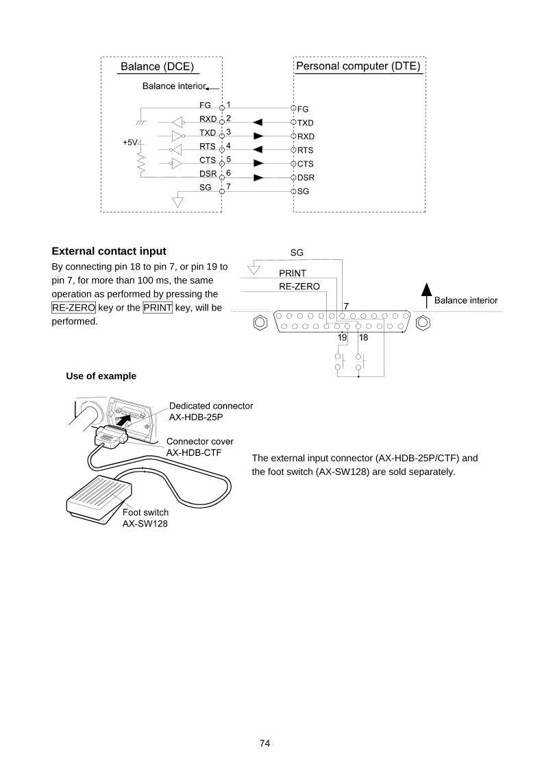
74
External contact inputBy connecting pin 18 to pin 7, or pin 19 topin 7, for more than 100 ms, the sameoperation as performed by pressing theRE-ZERO key or the PRINT key, will beperformed.
Use of example
The external input connector (AX-HDB-25P/CTF) andthe foot switch (AX-SW128) are sold separately.

75
15. CONNECTION TO PERIPHERAL EQUIPMENT
15-1 Connection to the AD-8121 PrinterSet the following parameters to use the AD-8121 printer.
Function setting Descriptiondout prt 0-3 Selects a print mode.dout ap-p 0-2 Selects the polarity for the auto print mode.dout ap-b 0-2 Selects the auto print difference.dout pU5e 0,1 Selects data output pause.5if bp5 2 Factory setting 2400 bps5if btpr 0 Factory setting 7 bits, Even parity check5if Crlf 0 Factory setting CR, LF5if Ct5 0 Factory setting CTS and RTS control, not used
When “MODE 1” or “MODE 2” of the AD-8121 printer is useddout 5-td 0 Factory setting Not to output the time and date.dout 5-id 0 Factory setting Not to output the ID number.dout at-f 0 Factory setting Not to use auto feed.5if type 0 Factory setting A&D standard format
When “MODE 3” of the AD-8121 printer is used.dout 5-td 0-3 Outputs the time and date as necessary.dout 5-id 0,1 Outputs the ID number as necessary.dout at-f 0,1 Uses auto feed as necessary.5if type 1 DP format
When data is transmitted continuously.When all memory data is transmitted at one time.dout pU5e 1 Uses pause.
NoteThe printer performs as follows, depending on the data memory setting.
Setting What is printeddata 0 The weighing datadata 2 The weighing data stored in memorydata 3 The calibration or calibration test data stored in memory
Refer to “10. ID NUMBER AND GLP REPORT” for a print sample.
15-2 Connection to a ComputerThe GP series balance is of the DCE type (Data Communication Equipment), which can beconnected to a personal computer using the RS-232C interface.Before connection, read the personal computer manual thoroughly.Use a standard DCE cable for connection (cable type: straight-through).When the personal computer type is a DOS/V with a 9-pin port, use a straight-through cable with a25-pin male connector and a 9-pin female connector.

76
15-3 Using Windows Communication Tools (WinCT)When Windows 95 or 98 is used as an operating system in a personal computer, the provided WinCTsoftware can be used to transmit the weighing data to the personal computer.The WinCT software has two communication methods: “RsCom” and “RsKey”. For details on WinCT,refer to the WinCT instruction manual.
RsCom� Can transmit commands to control the balance.� Can make bi-directional communication between the balance and a personal computer using
the RS-232C interface.� Can display or store the data using a text file format. Can also print the data using a printer
connected to the personal computer.� When several ports of a personal computer have balances connected, can communicate with
each balance simultaneously.� Can share a personal computer with other application software.� Can receive the balance GLP report.
RsKey� Can transmit the weighing data output from the balance directly to other application software
such as Microsoft Excel.� Can be used with most application software.
� Can receive the balance GLP report.
NoteWindows and Excel are registered trademarks of Microsoft Corporation.
15-4 Using the WinCT software, the balance can do the following:1 Analyzing the weighing data and the statistics with “RsKey”
The weighing data can be input directly into an Excel worksheet. Then, Excel can analyze thedata to obtain total, average, standard deviation, maximum and minimum value, and displaythem in a graph.
2 Controlling the balance using commands from a personal computerBy using “RsCom”, the personal computer sends commands such as “re-zero” or “sendweighing data” to the balance and controls the balance.
3 Printing the balance GLP report using your printerThe balance GLP report can be printed using a printer connected to the personal computer.
4 Receiving weighing data at a certain intervalThe weighing data can be received at a certain interval and data characteristic with elapsedtime can be obtained.
5 Using the GP series balance memory functionThe data can be stored in the balance’s memory. Of the data stored, the weighing data andcalibration data can be transmitted to a personal computer at one time.
6 Using a personal computer as an external indicatorWith the “RsKey” test mode function, a personal computer can be used as an external weightindicator for the balance. (To do this, set the balance data output mode to stream mode.)

77
16. COMMANDS16-1 Command ListNoteA command has a terminator added, that is specified using “5if Crlf5if Crlf5if Crlf5if Crlf” of the function table,and is sent to the balance.
Commands to query weighing dataC Cancels the S or SIR command.Q Requests the weighing data immediately.S Requests the weighing data when stabilized.SI Requests the weighing data immediately.SIR Requests the weighing data continuously.Commands to control the balanceCAL Same as the CAL key.OFF Turns the display off.ON Turns the display on.P Same as the ON:OFF keyPRT Same as the PRINT keyR Same as the RE-ZERO keySMP Same as the SAMPLE key.U Same as the MODE keyUN:mm Recalls the unit mass values in memory. (mm indicates 01-50)?UN Requests the unit mass numbers in memory.UW:∗∗∗∗∗∗∗∗∗∗∗∗∗∗∗∗∗∗∗∗∗∗∗∗ . ∗∗∗∗ g Changes the unit mass value. (Only “g” is available as a unit.)
Command e.g.: +002000.0 g(Set the unit mass value to 2000.0 g: indicates a space.)
?UW Requests the unit mass value.CN:mm Recalls the upper/lower limit value in memory (mm indicates 01-20)?CN Requests the upper/lower limit value code number of the selected value.H I:∗∗∗∗∗∗∗∗∗∗∗∗∗∗∗∗∗∗∗∗∗∗∗∗ . ∗∗∗∗ g Sets the upper limit values.
Command e.g.: HI:+002000.0 g(To set the upper limit value to 2000.0 g: indicates a space.)
LO:∗∗∗∗∗∗∗∗∗∗∗∗∗∗∗∗∗∗∗∗∗∗∗∗ . ∗∗∗∗ g Sets the lower limit values.Command e.g.:LO:+001000.0 g(To set the lower limit value to 1000.0 g: indicates a space.)
?HI Requests the upper limit value.?LO Requests the lower limit value.PN:mm Recalls the tare value in memory. (mm indicates 01-20)?PN Request the tare number of the selected value. (mm indicates 01-20)PT:∗∗∗∗∗∗∗∗∗∗∗∗∗∗∗∗∗∗∗∗ . ∗∗∗∗ g Sets the tare value.
Command e.g.:PT:+001000.0 g(To set the tare value to 1000.0 g: indicates a space.)
?PT Request the tare value.MCL Deletes all data in memory.MD:nnn Deletes data with the data number nnn.?MA Outputs all weighing data in memory.?MQnnn Outputs data with the data number nnn.?MX Outputs the number of data in memory (the last data number)
NotesWhen a unit is required in commands such as a “PT:” command, use the 3-digit unit code ofthe A&D standard format.nnn indicates a three-digit numerical value.

78
16-2 Acknowledge Code and Error CodesWhen the “Serial interface function (5if)” parameter is set to “erCd 1”, the balance outputs <AK>code or error code to each command as follows:
<AK> (06h) Acknowledge in ASCII code.
� When the balance receives a command to request data and can not process it, the balancetransmits an error code (EC, Exx).When the balance receives a command to request data and can process it, the balance outputsthe data.
� When the balance receives a command to control the balance and can not process it, thebalance transmits an error code (EC, Exx).When the balance receives a command to control the balance and can process it, the balancetransmits the acknowledge code.
Among commands to control the balance, the following transmit the acknowledge code bothwhen the balance receives the command and when the balance has accomplished thecommand. If the command can not be processed properly, the balance transmits an error code(EC, Exx). This error can be released using the CAL command.
CAL command (Calibration command) ON command (Display ON command)
P command (Display ON/OFF command) R command (RE-ZERO command)
� When a communication error has occurred due to external noise, or a parity error has occurred dueto transmission error, the balance transmits an error code. In this case, send the command again.
16-3 Control Using CTS and RTSDepending on the “Ct5” parameter of “Serial interface (5if)”, the balance performs as follows:
Ct5 0Regardless of whether the balance can receive a command or not, the balance keeps the CTS line HI.The balance outputs data regardless of the condition of the RTS line.
Ct5 1The CTS line is kept Hi normally. When the balance can not receive the next command (e.g. while thebalance is processing last command), the balance sets the CTS line to Lo. The balance confirms thelevel of the RTS line before outputting a set of data. If the RTS level is Hi, the balance outputs data. Ifthe RTS level is Lo, data is not output (The data is canceled).
16-4 Settings Related to RS-232CConcerning the RS-232C, the balance has two functions: “Data output (dout)” and “Serial interface(5if)”. Set each function as necessary.

79
17. MAINTENANCE� Do not disassemble the balance. Contact the local A&D dealer if the balance needs service or repair.
� Use the original packing material for transportation.
� Do not use organic solvents to clean the balance. Clean the balance with a lint free cloth that ismoistened with warm water and a mild detergent.
� The mass of the internal mass may change due to corrosion or other damage caused by the operatingenvironment, or due to aging. Check the internal mass using an external weight periodically.
18. TROUBLESHOOTING18-1 Checking the Balance Performance and EnvironmentThe balance is a precision instrument. When the operating environment or the operating method is
inadequate, correct weighing can not be performed. Place a sample on the pan and remove it, and
repeat this several times. If the balance seems to have a problem with repeatability or to perform
improperly, check as described below. If improper performance persists after checking, contact the
local A&D dealer for repair.
Checking that the balance performs properly� Check the balance performance using the self-check function as described in “6-1 Automatic
Response Adjustment / Self Check Function”.
An error display appears when a malfunction is found.
� Check the balance repeatability using an external weight. Be sure to place the weight in thecenter of the weighing pan.
� Check the balance repeatability, linearity and calibrated value using external weights with a known value.
Checking that the operating environment or weighing method is properOperating environment� Is the weighing table solid enough?
� Is the balance level? Refer to “3-1 Before Use”.
� Is the operating environment free from vibration and drafts?
� Is there a strong electrical or magnetic noise source such as a motor near the balance?
Weighing method� Does the weighing pan touch the breeze ring or anything? Is the weighing pan installed correctly?
� Is the RE-ZERO key pressed before placing a sample on the weighing pan?
� Is the sample placed in the center of the weighing pan?
� Has the balance been calibrated using the internal mass (one-touch calibration)?
� Has the balance been warmed up for 30 minutes before weighing?

80
Sample and container� Has the sample absorbed or lost moisture due to the ambient conditions such as temperature
and humidity?
� Has the temperature of the container been allowed to equalize to the ambient temperature?Refer to “3-2 During Use”.
� Is the sample charged with static electricity? Refer to “3-2 During Use”.
� Is the sample of magnetic material such as iron? Caution is required for weighing magneticmaterials. Refer to “3-2 During Use”.
18-2 Error Codes Display Error code Description
EC, E11 Stability errorThe balance can not stabilize due to an environmentalproblem. Prevent vibration, drafts, temperaturechanges, static electricity and magnetic fields, frominfluencing the balance.Refer to “3. PRECAUTIONS” for details on the operatingenvironment and “6. RESPONSE ADJUSTMENT/SELFCHECK FUNCTION” about adapting the balance to theenvironment.To return to the weighing mode, press the CAL key.Out of the setting rangeThe data to be stored is out of the setting range.
EC, E16 Internal mass errorApplying the internal mass does not yield a change inthe weight value as specified.Confirm that there is nothing on the pan and perform theweighing operation from the beginning again.
EC, E17 Internal mass errorThe internal mass application mechanism does notfunction properly.Perform the weighing operation from the beginningagain.
EC, E20 Calibration weight errorThe calibration weight is too heavy. Confirm thecalibration weight value.Press the CAL key to return to the weighing mode.
EC, E21 Calibration weight errorThe calibration weight is too light. Confirm thecalibration weight value.Press the CAL key to return to the weighing mode.Overload errorA sample beyond the balance weighing capacity hasbeen placed on the pan.Remove the sample from the pan.

81
Display Error code DescriptionWeighing pan ErrorThe weight value is too light.Confirm that the weighing pan is properly installed andcalibrate the balance.Sample mass errorThe balance can not store the sample for the countingmode or for the percent mode because it is too light.Use a larger sample.Unit mass errorThe sample unit mass for the counting mode is too light.Storing and using it for counting will cause a countingerror.Add samples to reach the specified number and pressthe PRINT key.Pressing the PRINT key without adding samples willshift the balance to the counting mode. But, to acquireaccurate weighing, be sure to add samples.Automatic response adjustment zero errorThe automatic response adjustment can not beperformed because there is something on the pan.Clear the pan. Press the CAL key to return to theweighing mode.
(CHECK NG)
Automatic response adjustment unstable errorThe automatic response adjustment can not beperformed because the weight value is unstable.Check the ambient conditions such as breeze,vibration and magnetic fields, also check the weighingpan. Press the CAL key to return to the weighing mode.
(CHECK NO)
Internal errorIndicates an internal error as the result of self-checkfunction.Repair is required. Contact the local A&D dealer.Clock battery errorThe clock backup battery has been depleted.Press any key and set the time and date. The clock andcalendar function works normally as long as the ACadapter is connected to the balance. If this error appearsfrequently, contact the local A&D dealer.
(Blinking)
Memory fullThe amount of weighing data in memory has reachedthe maximum capacity.Delete data in memory to store new data. For details,refer to “11. DATA MEMORY”.
(Illuminated)Memory fullThe amount of calibration or calibration test data inmemory has reached the maximum capacity (50 sets).The data in memory will be deleted automatically tostore new data. For details, refer to “11. DATAMEMORY”.

82
Display Error code DescriptionMemory type errorType of memory set in the function table and type ofdata stored are different.For details, refer to “11. DATA MEMORY”.
EC, E00 Communications errorA protocol error occurred in communications.Confirm the format, baud rate and parity.
EC, E01 Undefined command errorAn undefined command was received.Confirm the command.
EC, E02 Not readyA received command can not be processed.e.g. The balance received a Q command, but not in the
weighing mode.e.g. The balance received a Q command while
processing a RE-ZERO command.Adjust the delay time to transmit a command.
EC, E03 Timeout errorIf the timeout parameter is set to “t-Up1”, the balancedid not receive the next character of a command withinthe time limit of one second.Confirm the communication.
EC, E04 Excess characters errorThe balance received excessive characters in a command.Confirm the command.
EC, E06 Format errorA command includes incorrect data.e.g. The data is numerically incorrect.Confirm the command.
EC, E07 Parameter setting errorThe received data exceeds the range that the balance can accept.Confirm the parameter range of the command.
Other errors If the errors described above can not be released orother errors are displayed, contact the local A&D dealer.
Other symbol
When this indicator blinks, automatic self calibration isrequired. The indicator blinks when the balance detectschanges in ambient temperature. If the balance is notused for several minutes with this indicator blinking, thebalance performs automatic self calibration. The blinkingperiod depends on the operating environment.
18-3 Asking For RepairIf the balance needs service or repair, contact the local A&D dealer.
The balance is a precision instrument. Use much care when handling the balance and observe thefollowing when transporting the balance.
� Use the original packing material.
� Remove the weighing pan from the main unit.

83
19. SPECIFICATIONSGP-12K GP-20K GP-22K GP-30K/GP-30KS
Weighing capacity 12 kg 21 kg 21 kg 31 kgMaximum display(See bottom for the description of ∗ )
12.0084 kg 21.0084 kg 21.008 kg/6.1009 kg∗
31.0084 kg
Minimum weighing value (1 digit) 0.1 g 1 g/0.1 g 0.1 gRepeatability (Standard deviation) 0.1 g 0.5 g/0.1 g 0.1 gLinearity ±0.2 g ±1 g/±0.2 g ±0.2 gStabilization time (typical at FAST) Approx.1.5 secondsSensitivity drift (10°C-30°C/50°F-86°F ) ∗∗ ±3 ppm/°C ±5 ppm/°C ±3 ppm/°C
±1.0 g ±1.5 gAccuracy right after calibration usingthe internal mass. ∗∗∗ The value above is to the weighing capacity.
Minimum unit mass 0.1 g 1 g 0.1 gCountingmode Number of samples 10, 25, 50 or 100 pieces
Minimum 100% reference mass 10 g 100 g 10 gPercentmode Minimum 100% display 0.01%, 0.1%, 1% (Depends on the reference mass stored.)External calibration weight 5 kg, 10 kg 10 kg, 20 kg 20 kg,30 kgWeighing pan 384 x 344 mmExternal dimensions (WxDxH, mm) 372 x 615 x 130 (GP-30KS: 344 x 442 x 130 ) ∗∗∗∗Net weight Approx. 17 kg
GP-40K GP-60K GP-100K/GP-100KS GP-102KWeighing capacity 41 kg 61 kg 101 kgMaximum display (See bottom for ∗ ) 41.0084 kg 61.084 kg 101.084 kg 101.08 kg/61.009 kg∗Minimum weighing value (1 digit) 0.5 g 1 g 10 g/1 gRepeatability (Standard deviation) 0.5 g 0.7 g 1 g 5 g/1 gLinearity ±1 g ±2 g ±10 g/±2 gStabilization time (typical at FAST) Approx.1.5 secondsSensitivity drift (10°C-30°C/50°F-86°F ) ∗∗ ±5ppm/°C ±6ppm/°C ±10 ppm/°C
±1.5 g ±5 g ±10 gAccuracy right after calibration usingthe internal mass. ∗∗∗ The value above is to the weighing capacity.
Minimum unit mass 0.5 g 1 g 10 gCountingmode Number of samples 10, 25, 50 or 100 pieces
Minimum 100% reference mass 50 g 100 g 1000 gPercentmode Minimum 100% display 0.01%, 0.1%, 1% (Depends on the reference mass stored.)External calibration weight 20 kg, 30 kg
40 kg30 kg, 40 kg50 kg, 60 kg
60 kg, 80 kg, 100 kg
Weighing pan 384 x 344 mm 386 x 346mmExternal dimensions (WxDxH, mm) 372 x 615 x 130 373 x 615 x 130 (GP-100KS: 346 x 443 x 130 ) ∗∗∗ ∗Net weight Approx. 17 kg Approx. 18 kg
Specifications common for any modelDisplay refresh rate 5 times/second or 10 times/secondOperating environment 5°C to 40°C (41°F to 104°F), 85%RH or less (No condensation)Dust and water protection Complying with IP65Sensor used Super Hybrid Sensor (SHS)AC adapter Confirm that the adapter type is correct for the local voltage and
power receptacle typePower consumption Approx. 14VA (supplied to the AC adapter )Interface (Provided as standard) RS-232C with Windows Communication Tools WinCT∗ The GP-22K and GP-102K allow weighing using a precision range, even with a heavy tare
placed on the pan. (Smart range function)∗∗ When automatic self calibration is not used, at 10° C to 30° C (50° F to 86° F)∗∗∗ Accuracy right after calibration using the internal mass in good ambient conditions (within the
temperature range of 10°C to 30° C (50° F to 86° F) with no abrupt changes in temperature orhumidity, no drafts, no effect by magnetic fields or static electricity).Check the internal mass periodically as described in “17. MAINTENANCE”.
∗∗∗∗ The size for the GP-30KS/100KS is that of the main unit. The display size is 260x164x202.The cable length, for the separate display type balances (GP-30KS/100KS), is 3 meters.

84
20. EXTERNAL DIMENSIONS Standard Type: GP-12K/20K/22K/30K/40K/60K/100K/102K
NoteThe size in parentheses is for the GP-100K/102K Unit: mm

85
Separate Display Type: GP-30KS/100KS
NoteThe size in parentheses is for GP-100KS Unit: mm

86
21. OPTIONSAD-8121 Printer
� Compact thermal dot-matrix printer� Statistical function, clock and calendar function, interval
print function, graphic print function, dump print mode� 5 x 7 dots, 16 characters per line� Print paper (AX-PP143, 45 (W) x 50 (L) mm , ø65 mm)� AC adapter or alkaline battery
OP-04: Comparator output (relay/ with a buzzer)/RS-232C/Current loop� Generates a relay output corresponding to HI , OK and LO in the display.� Current loop and RS-232C can be used at the same time. For example, a personal computer
and an AD-8121 printer can be used simultaneously.� Installed in place of the standard RS-232C serial interface.
OP-06: Analog voltage output/Current loop� Gains a voltage of 0-1V (or 0.2-1V) depending on the displayed value.� With this option, current loop can be used. For example, an AD-8121 printer can be used
simultaneously using this option.� Installed in place of the standard RS-232C serial interface. So, RS-232C is not available for use.
OP-07: Extension cable, 5 m (Available as factory option only when ordered with a GP balance)� Applicable balance models: GP-30KS/100KS� A cable of 5 meters, to connect between the display and the main unit
OP-20: Underhook� Applicable balance models: GP-12K/20K/22K/30K/30KS/40K� Used for measuring the density of magnetic materials and concrete (coarse aggregates).
OP-21: Underhook� Applicable balance models: GP-60K/100K/100KS/102K� Used for measuring the density of magnetic materials and concrete (coarse aggregates).
OP-22: Printer bracket� Used to place the AD-8121 printer beside the display.
AD-1682 Rechargeable battery� Allows use of the balance in a place where AC power is not available.
AD-8524A/B: Keyboard adapter� Used to connect the balance to a personal computer with appropriate OS and applications.
AD-8920: Remote display� Connected to the GP series using the RS-232C interface.
AX-SW128: Foot switch� Used to externally transmit a RE-ZERO or PRINT signal to the balance.

87
22. TERMS/INDEXTermsStable value The stable weight data, indicated by the illuminated stabilization indicator.
Environment Ambient conditions such as vibration, drafts, temperature, static electricityand magnetic fields which affect the weighing operation.
Store To save the weighing data, unit mass or calibration data using the datamemory function.
Calibration Adjustment of the balance so that it can weigh accurately.
Output To output the weighing data using the RS-232C interface.
Zero point A weighing reference point. Usually refers to the value displayed whennothing is on the weighing pan.
Smart range function Allows weighing in the precision range, even if a heavy tare is used.
Data number Numbers assigned sequentially when weighing data or unit weight is stored.
Digit The minimum weighing value available. Used for the balance, 1 digit is thesmallest displayable mass.
Tare To cancel the weight of a container which is not to be included in theweighing data. Normally, refers to an operation of placing a container and
setting the display to zero.
Mode Balance operational function.
Re-zero To set the display to zero.
GLP Good Laboratory Practice.
Repeatability Variation in measured values obtained when the same mass is placed andremoved repetitively. Usually expressed as a standard deviation.
e.g. Standard deviation=1 digit: This means that measured values, obtained
when the same sample is placed and removed repetitively, fall within ±1 digitin the frequency of about 68%.
Stabilization time Time required after a sample being placed, until the stabilization indicatorilluminates and the weighing data is displayed.
Sensitivity drift An affect that a change in temperature causes to the weighing data.Expressed as temperature coefficient.
e.g. Temperature coefficient = 2 ppm/° C : If a load is 20 kg and the
temperature changes by 10° C, the value displayed changes by the followingvalue.
0.0002%/°C x 10°C x 20 kg = 0.4 gIn this example, if the value displayed is 20.0000 kg before temperature
changes, a temperature change of 10° C will make the value displayed20.0004 kg.

88
Index
Keys and symbols ON/OFF key ................................................. 10 SAMPLE key .......................................... 10, 11 MODE key .............................................. 10, 12 CAL key........................................................ 10 PRINT key .................................................... 10 RE-ZERO key..................................... 8, 10, 11 Stabilization indicator............................... 10 Interval memory active indicator.............. 10 Interval memory standby indicator........... 10 Prior notice indication of automatic self
calibration ................................................ 10 Processing indicator ................................ 10
- A -A&D standard format ............................................... 39ACAI ................................................................ 17Accumulation function ........................................ 19 37AD-1682 ................................................................ 86AD-8121 .......................................................... 75, 86AD-8524A/B............................................................. 86AD-8920 ................................................................ 86Animal mode indicator ....................................... 10, 36Auto display-OFF..................................................... 37Auto display-ON ...................................................... 37Automatic Response Adjustment............................. 21Automatic Self Calibration ....................................... 24Auto print mode ....................................................... 38AX-SW128............................................................... 86
- C -Calibration ................................................... 23, 24, 25Calibration test......................................................... 27Comparator indicators ............................................. 10Comparator function ................................................ 46CSV format .............................................................. 40
- D -Data memory ........................................................... 54Data number............................................................ 41Digit .......................................................... 26, 27DP format ................................................................ 39
- E -EC, E00 ................................................................ 82EC, E01 ................................................................ 82EC, E02 ................................................................ 82EC, E03 ................................................................ 82EC, E04 ................................................................ 82EC, E06 ................................................................ 82EC, E07 ................................................................ 82EC, E11 ................................................................ 80EC, E16 ................................................................ 80EC, E17 ................................................................ 80EC, E20 ................................................................ 80EC, E21 ................................................................ 80External contact input ........................................ 73, 74
- G -GLP ............................................................ 3, 51Capacity indicator .......................................... 4, 10, 37
- H -Hold function............................................................ 36
- I -ID number.......................................................... 41, 50Inhibit ................................................................ 30Initializing the Balance............................................. 31Interval memory mode............................................. 39
- K -Key mode ................................................................ 38KF format ................................................................ 40
- L -Linearity .......................................................... 79. 83 lo .......................................................... 16, 81LO ............................................................ 3, 46
- M -Memory full .............................................................. 81MT format ................................................................ 40
- N -NU format ................................................................ 40
- O -100% reference mass.............................................. 18OP-04 ................................................................ 86OP-06 ................................................................ 86OP-07 ................................................................ 86OP-20 ................................................................ 86OP-21 ................................................................ 86OP-22 ................................................................ 86
- P -Percent Mode .......................................................... 18Permit ................................................................ 30
- R -Repeatability...................................................... 79, 83Response adjustment .............................................. 21RsCom ................................................................ 76RsKey ................................................................ 76
- S -Self check function .................................................. 21Sensitivity drift ......................................................... 83Smart range function ............................................... 11Stability band width .................................................. 36Stabilization time...................................................... 83Stream mode ........................................................... 38
- U -Underhook ....................................................... 4, 8, 86Unit mass16Units ................................................................ 12
- W -Warm up 6, 7, 8, 37Weighing pan......................................................... 5, 6Weighing capacity................................. 4, 8, 37 80, 83WinCT ............................................................ 4, 76
- Z -Zero point26, 28, 37, 87Zero tracking............................................................ 37

ページ 1
[ Blank page ]

������� ������� ��� ���� ������ �� �� �� �������� �������������� !"�# $�% &�'��(��� )* !"�# $�% &�'��(��"�++� ,,---.�//.0�.1�,
234 5678655�8679 86:;�&&&� <0=�/�� >��?�� <����+� =�. '&��& @.A.�.��������� !�# $��"% �(��&��� )* !�# $��"%�(�����'
234 86����B56�� C�4;@��+ ��,�( D�0 ��/ E�� �����/�� D���� �� � �����/��� F*�� FG�� �>H @��+�/ I���/����������� !��# $���&% &&���� )* !��# $���&% &&��"&
J7���� ����� K ��LD����� A+� � (�� (���� )�� M��+,<�� &� NOP<��H��������� !�'# $('% &������� )* !�'# $('% &�����&�
234 B5�:��� ���; C�4;�� >�- A+���+� �����+��� A��+� ��+��� &��� �@A�P�Q����������� !(�# $"% "�&������ )* !(�# $"% "�&�����'
234 RK�52 C������"+� )����� <��++� D�/�. �(�� H��/��/���� H����/������� �� A����� IFPO���������� !"�# $�% �"������ )* !"�# $�% �"����"�