Embed Size (px)
Citation preview

JOURNAL OF RESEARCH of the National Bureau of Standards - C. Engineering and Instrumentation Vol. 74C, Nos. I and 2, January-June 1970
Precise Continuous Optical Attenuator:::
G. Ruffino**
(November 17, 1969)
The construction of a preCISIOn photometric attenuator is described, which uses linear bire· f rin genl polarizers. If properly calibrated, the instrument has relative error not exceeding 2.4 X 10-' within a relative transmittance range down to 8 X 10-". The calibration takes into account stray li ght, provided the ratio of stray light intensity to total intensity remains constant and low in the whole range. The construction and calibrating procedure apply equa lly well to the near infra red reg ion.
Key words: Dich roic polarizers; optics; pyrometry; radiometry; relati ve transmittance factor.
1. Introduction
Very accurate radiometric and pyrometric measure· ments often require relati ve transmittance factors to be measured with an accuracy of the order of 10-4 . Fixed values of these factors having this order of accuracy may be realized with rota ting sectors, where the angular open· ings of the sector gives the attenuation.
Suitable means for producing a continuously yariable ) relative transmittance factor which may be measured as
a function of a mechanical quantity can be constructed with a set of light polari zers. A good arrangement con· sists of three linear dichroic polarizers lying in pa rallel planes, the first and third of them having fixed pa ra llel orientation ( fig. 1).
I ",
The middle polarizer can rotate in its plane, a being the angle between the rota ting and fixed axes. R. Clark Jones [IP calculated the transmittance of such a train of three birefringent polarizers, which, for the most general case of three nonidentical polarizers, is given by the following expression:
(1)
FIGURE 1. The triple-polaroid optical attenuator.
T(a)_ 4 T(O) -COS a. (2) where the coefficients are functions of the two principal
transmittances of the polarizers-the subscripts applying I to each of them- and 82 is the phase retardation of the , middle polari zer.
H . E. Bennett [2] described a mechanical arrangement r . of three polarizers in seri es for producin g optical attenua-
For this to hold with an accuracy better than 10-3, the principal transmittance ratio of the birefringent polarizers must be < 4 X 10⁻⁶•
I ti on. He showed tha t, if high grade identical polarizers are selected, the relative transmittance factor for the angles a and 0 is given by the simple relation :
*An invit ed paper. **Present address : Ins tituto di Metrol ogia G. Co lonnet ti. T orino. Italy . Professor
Ruffino was a gues t worke r in the Hea t Di vision, Institu te for Basic Standard s, Nati ona l Bureau of St anda rds , Washington. D. C. 20234, Fe bruary to July 1969.
( 1 Fi gures in brac ke ts ind ica te the lit e ra ture re feren ces at the e nd of this paper.
9
In connection with the development of a photoelectric pyrometer a polaroid attenuator has been constructed, which is basically similar to the one described by Bennett, with provisions for meeting the following major requirements:
(1) the middle polarizer should have the highest resetability;

(2) its rotation angle must be measured with high precision;
(3) the attenuators may be calibrated at a discrete set of points, yielding the coefficients of a function relating the angle with the relative transmittance factor, without any special requirement for the quality of the polarizers.
2. Theory
Equation (1) may be arranged in the following form:
with: a= S]S2Sg+ D2 (SlDg +SsD1 ) +SsDIDa b = 2D2 (S]Da + SaDl) C=DIDa(Ss-P2 cos 82),
The transmittance with parallel axes is
T(O) =a.
(3)
(4)
Let <I> be the radiant flux of a beam entering the system, <1>0 the emerging flux with the polaroid set with parallel axes and <l>a the emerging flux corresponding to the rotation a of the middle polarizer. Then the relative transmittance factor angle a will be:
(5)
R f · (3) d . A b d Be. . e errmg to an puttmg =- an =-, It IS a a
easily seen that
which gives the relative transmittance factor as a function of a, provided the coefficients A and B are known.
We may expect that not alI the incident flux will be attenuated according to eq (3 ) . Then, for every angle, we suppose the incident flux <I> to be divided in two portions: the first <1>*, which is attenuated according to (3) and the second ~<I> attenuated by a different amount T'(a). We call ~<I> the stray flux, or "stray light."
Now we set two limitations to this stray flux: (1) it is a small fraction, which will be defined later,
of the total flux; (2) the proportion between stray and total flux is
constant for any angle. The second hypothesis leads to the following expressions
for the emerging flux:
<I>~=T(O) <I>*+T'(O) ~<I>
<I>~=T(a) <I>*+T'(a) ~<I>.
The transmittance ratio is then:
(7)
(8)
10
~!J~L[l+I'(a) ~<I> - T'(O) ~<I>] -T(O) T(a) <1>* T(O) <1>*
=T ( ) [1- T'(~2 ~<I>] + T'(a) ~<I> r a T(O) <1>* T(O) <1>*'
The approximation involved in the second equation is acceptable provided
I [T'(a) - T'(O)] T'(O) (~<I» 2 I 1 T(a) T(O) T(O) <1>* < <
which gives a quantitative expression to the first hypothesis. Putting
and taking into account eq (6), eq (8) maybe written:
If the last term is
I T'(a) -T'(O) ~<I> I .... * «1 T(O) '*'
then it may be neglected and the transmittance ratio becomes:
or:
Tr'(a) = 1- (l-K) A sin2 a- (l-K) B sin2 2a (10)
T,.*(a) = l-A* sin2 a- B* sin22a.
Therefore the stray light, at least as defined here, affects only the value of the constant coefficients of the expression of the relative transmittance factor.
1
~
The conclusion is that eq (6) yields the relative transmittance factor of a train of three birefringent polarizers in the most general case in which they are not equal, their extinction is not null, and stray flux, under specified l'.~ conditions, is present in the system.
3. Mechanical Design
An attenuator using sheet polarizers 2 and embodying ,I
the above theory has been constructed. A longitudinal section is represented in figure 2. The instrument consists",) of five principal parts:
(1) A rotor R holds the middle polarizer P 2 and a glass graduated circle C centered on the rotation axis. The latter is divided in degrees and is a component of a pre- . cision survey instrument.s :
2 Type HN·22, selected to have a principal transmittance ratio:::; 4 X 10⁻⁸, 3 Made by Salmoiraghi. Italy. \~
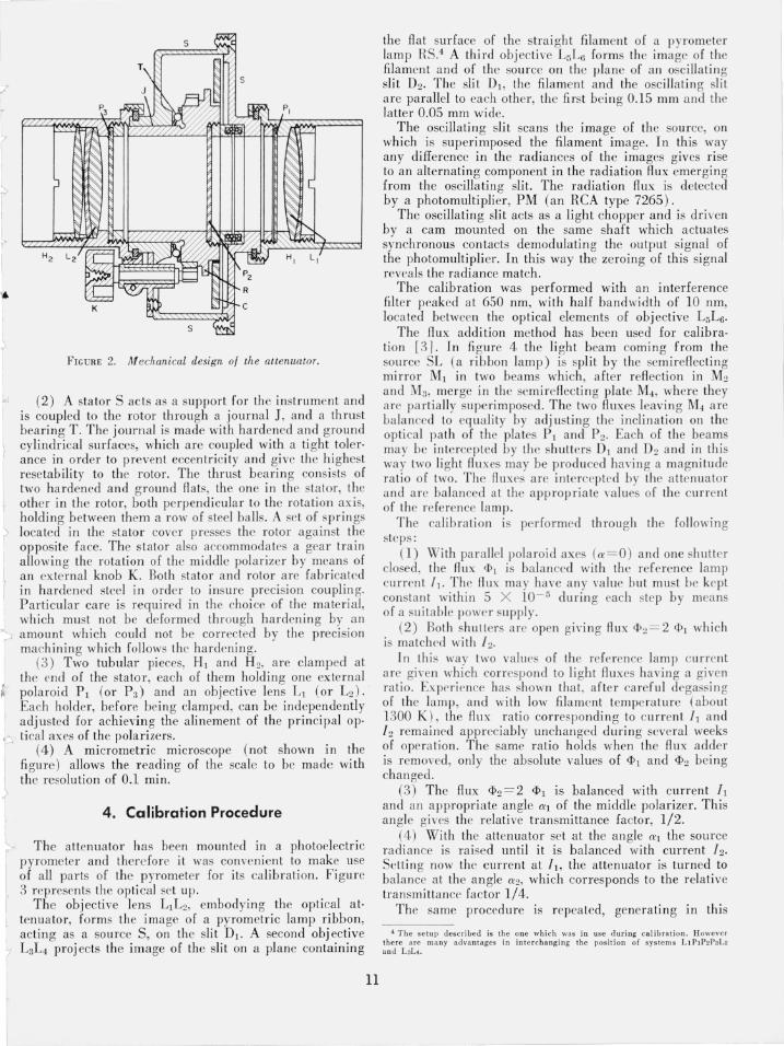
FIGURE 2. Mechanical design 0/ the attenuatar.
'" (2) A stator S acts as a support for th e instrument and is coupled to the rotor through a journal 1, and a th rust bearing T . The journal is made with hardened and g round cylindrical surfaces, which are coupled with a ti ght tol er· ance in ordcr to prevent eccentri city and give the highest rese tability to the rotor. The thrust bea ring consists of two hardened and g round flats, the one in thc stator, the other in the rotor, both perpendicular to the rotati on ax is, holding between them a row of steel balls. A se t of springs r located in the stator cover presses thc ro tor aga inst the opposite face. The s tator also accommoda tes a gear train allowing the rotation of the middle polarizer by means of an external knob K. Both stator and rotor are fabricated in hardened steel in order to insure precision couplin g. Particular care is required in the choice of the ma teri a l, which must not be deformed th rough hardenin g by an amount which could not be correc ted by the precision machining which follows the hardening.
(3) Two tubular pieces, HI and H 2, are clamped at the end of the stator, each of them holding one external pola roid PI (or Pa) and an objective lens L t (or L2)' Each holder, before being clamped, can be independently adjusted for achieving the alinement of the principal op·
<". tical axes of the polarizers. r (4) A micrometric microscope (not shown in the I fi gure) allows the reading of the scale to be made with ~ the resolution of 0.1 min.
4. Calibration Procedure
The attenuator has been mounted in a photoelectric pyrometer and therefore it was conve ni ent to make use of all parts of thc pyrometer for its calibration. Fi gure 3 represrnts the optical set up.
The obj ecti ve lens LIL2, embod ying the optical at· tenuator, forms the image o( a pyrometrie lamp ribbon,
t acting as a source S, on the slit D I . A second obj ective (' L3L4 proj ects the image of the slit on a plane containing
11
the fl at surface of the strai ght fil ament of a pyrometer lamp RS.4 A third obj ective L5L6 forms thc image of the filament and of the sourcc on the plane of an oscilla ting slit D2 • The slit DI , the filament and the oscillating slit are parallel to each other, the first being 0.15 mm and the latter 0.05 mm wide.
The oscillating slit scans the image of the source, on which is superimposed the filament image. In this way any difference in the radiances of the images gives ri se to an alternating component in the radiation flux emerging from the oscillating slit. The radiation flux is detec ted by a photomultiplier, PM (an RCA type 7265) .
The oscillating slit acts as a light chopper and is driyen by a cam mounted on the same shaft which actuates synchronous contacts demodulating the output signal of the photomultiplier. In this way the zeroing of this signal reveals the radiance match.
The calibration was performed with an interference filter peaked a t 650 nm, with half bandwidth of 10 nm, loca ted between the optical elements of obj ective L5L6'
The flux addition method has been used for calibra· ti on [31. In fi gure 4 the li ght beam comin g from the source SL (a ri bbon lamp ) is split by the semirefl ecting mirror Ml in two bea ms which, after refl ection in Mz and M3, merge in thc semi refl ectin g plate M4 , where they a re pa rti ally superimposed. The two flu xes leaving M4 are ba lanced to equa lity by adjusting the inclin ation on the opti cal path of the plates P I and P 2. Each of the beams may be intercepted by the shutters DI and D2 and in this way two light flu xes may be produced havi ng a magnitude rati o of two. The fluxes are intercepted by the at tenuator and are balanced at the appropr iate va lues of the current of the reference [amp .
The calibra ti on is pe rformed through the following steps:
(1) With par allel pola roi d axes (a=O) and one shutter closed, the flu x 1>1 is ba lanced with the reference lamp current I J • The fl ux may have any value but must be kept constant with in 5 X 10- 5 du ring each step by means of a sui table power snpply.
(2) Both shutters arc open givi ng flu x <1'>2 = 2 <PJ which is matchrd with 12 .
In this way two values of the re ferrnce lamp current are gi\'en which correspond to light flu xes havi ng a given ra tio . Expf'rience has shown tha t, after careful degassing of the lamp, and with low fil ament tempera ture (abou t 1300 K ), the flu x ratio correspondin g to current II and 12 remained appreciably unchanged during several weeks of opera ti on. The same ratio holds when the flux adder is removed, only the absolute values of <1>1 and <1>2 being changed .
(3) The flux <1>2 = 2 <1>1 is balanced with current I I and an a ppropriate angle al of the middle polarizer. This angle gives the relative transmittance fa ctor, 1/2.
(4) With the attenuator set at the an gle al the source radi ance is rai sed until it is balanced with current 12•
Setting now the current at IJ, the attenuator is turned to balance at the angle a 2, which corresponds to the relative transmittance factor 1/4.
The same procedure is repeated, generating in this
4 The se tu p descr ibed is the o ne whi ch was in use during ca libratio n. Howeve r the re ure many advantages in int erchanging the pos iti on of systems LIP1P2PaL2 and L3L{.

FIGURE 3. Optical setup.
t P2 u m "'tit":', ~ 0 RL
0 A
SL
M, P, I~ D,
FIGURE 4. The calibration arrangement.
way a geometric series of values of the relative transmittance factors having seven terms.
The actual calibration was performed by sweeping the entire relative transmittance range seven times, proceeding stepwise from the lowest value, allowing due time for stabilization, and always using the same two values of the reference currents. For each point two readings were made so that for each nominal value of the relative transmittance factor a total of 14 readings were taken_ Table 1 reports, in successive columns, the nominal values of the relative transmittance factor, the mean value of the angle, the estimated standard deviation of a reading and the estimated standard deviation of the mean.
TABLE 1
T, a s m .. 2-1 32° 48.44' 0.54' 0.16' 4 -1 45° 5.70' .50' _14' 8-1 53° 40.32' .41' .11'
16-1 60° 14.11' .32' .09' 32-1 65° 28.42' .25' .07' 64-1 69° 46.04' .29' .08'
128-1 73° 2l.55' .22' _07'
5. Treatment of Calibration Data
The constant coefficients of eq (6) now may be determined through the least squares method on the basis of the calibration data. But first two remarks have to be made:
(1) The first attenuation step, T,o!, is affected by an error which is mainly due to inequality of the two fluxes which are added to create the ratio 1/2. Any other value of the attenuation is generated by multiplying the preceding one by T,ob expressed as
(12)
in which i is the serial number of the step. Obviously the
12
I multiplication by Trl propagates the error by which it ) itself is affected. ~
(2) The transmission ratio decreases rapidly with increasing angleso Therefore equal deviations of their calculated values from the experimental ones may lead to enormous relative errors for the lowest transmittance ratios. This must be avoided.
On this basis the coefficient A and B are determined i according to the following procedure. .4\'
(l) We form a series of relative transmittance factors, I
each term being formed according to eq (12). Giving to the first term T"l values which are closely and equally !
spaced around the expected value, for each of them we form a series of relative transmittance factors. Then, for each series, we minimize the function:
7 <I> (A,B) = ~
i=1
(13)
Each term of this function is the square of the relative deviation, which is the difference between experimental and computea values divided by the experimental value. 1 Each value of Trl yields a value of A and of B.
(2) With each set of values of A and B the following I quantities are computed: '
(a) Trc= 1-A sin2 a- B sin2 2a
(b) Ec=Tr-Trc
(c) 7Jc= ;:
(d) - dTrc ( Ee - da Sm experimental absolute error)
(e) 7Je =~; (experimental relative error) .
I r:
(3) Finally, among the ensemble of the groups of Trc , <'I
A and B values, the one is chosen for which Ec< Ee. In J
this way the errors of the relative transmittance factor ' given by the fitting formula lies within the uncertainty of. / the experimental values. A program embodying this I procedure has been put in a computer and the results of 1
the best fit are collected in table 2. The equation of the relative transmittance factor for the '
polaroid train tested is I 1
(14) '<

)
- ------- -
TABLE 2
a Tr T" Ec 7Jc E, 71,
32° 4B.44' 0.50175 0.501B1 -5.B X 10-5 -1.2 X 10-' 6.0 X 10⁻⁵ 1.2 X 10-' 45° 5.70' .25175 .25172 3.5 X 10⁻⁵ 1.4 X 10-' 4.1 X 10⁻⁵ 1.6 X 10-' 53° 40.32' .12632 .12630 1.4 X 10-' l.lX 10-' 2.2 X 10⁻⁵ 1.7 X 10-' 60° 12.11' .0633BO .063377 0.2 65 ° 28.42' .031801 .031805 - .4 69 ° 46.04' .015956 .0159560 73° 21.55' .~OB0059 .00080057
p
FIGURE 5. Optical attenuation versus angular setting.
which is plotted in figure 5 (the vertical line in the diagram represents the upper limit of calibrated range).
6. Discussion
From the last column of table 2 it is apparent that the optical attenuator here described may be calibrated in the range from 1 to 8 X 10- 3 of the transmission ratio, with a maximum random error of 2.4 X 10- 4 • From the calibration data are computed the constant coefficients of the theoretical interpolating equation, which gives the
0 .2
X 10-5 0.4 X 10-' 1.1 X 10⁻⁵ 1.8 X 10-' X 10-5 -1.3 X 10-' 0.5 X 10⁻⁵ 1.7 X 10-'
0 .4 X 10-5 2.4 X 10-' X 10-' 0.2 X 10-' .2 X 10-5 2.4 X 10-'
Very important is the fact that the formula glvmg the attenuation as a function of the angle, under certain general conditions, takes into account the stray light.
From the operation and the calibration procedure of the instrument it is apparent that its precision is subject to a few limi tations:
(I) - Unfortunately the transmittances and their ratio in birefringent polarizers are not wavelength independent. Polarizer sheets are manufactured to have roughly constant parameters over the entire visible radiation band and in the near infrared. Therefore, for the hi ghest precision , they must be calibrated within a narrow bandwidth at each wavelength for which they are intended to be used.
(2) - It is well known that several sources, such as incandescent lamps, emit partially polarized radiation. In this case the present device attenuates the polarized component accordin g to the angle between the polariza. tion plane and the optical axis of the outer polarizers. This fa ct is not obj ectionable when the instrument is used for generatin g different flu x values from a constant source, since the relative transmittance factor is independent of the polarization sLate of the entering radiation.
(3) - The attcnuator has been calibrated with a parallel radiation beam. Since the transmittance and the reta rda· tion depend on the propagation direction of the radiation through the polarizing sheets, calibration precision will be assured only if the attenuator is operated with plane waves. Therefore the target a rea should have small di· mensions and the source should be placed in the focal plane of the front lens of th e instrument.
On the other hand, thi s device has an important advan tage in the fact that the interpolating equation does not make any assumption about the ratio between the principal transmittances of the birefringent polarizers. This means that an accurate calibration may be per· formed even when that ratio is rather high, which opens the way to the use of accurate optical attenuators in the near infrared.
The author is grateful to A. Rosso and G. Canta of the Colonnetti Institute of Metrology for the skillful construction of the instrument and for the help which the former gave in its testin g.
7. References [I) Clark Jones, R., 1. Opt. Soc. Am. 46, 528 (1956) . [2] Bennett, H. E. , A ppJ. Opt. 5, 1265 (1966). [3] Gordov, A. N., Lapina, E. A., Exp. Techn. 5, 544 (1958);
Bojarski, L. A., Proc. Verb. Com. Int . Poids Mes. 26A, Tl50 (1959); Erminy, D. E. , 1. Opt. Soc. Am. 53, 1448 (1963 ); Lee, R. D. , Metro!' 2, 150 (1966).
;I intermediate values well within the experimental errors. (Paper 74Cl&2-294)
13