Embed Size (px)
Citation preview
uopTM
TABLE OF CONTENTS
SECTION ITHE NATURE OF ADSORBENTS AND THEIR OPERATION . . . . . . . . . . . . . . . . . . . . . . . . . . . . . . . . . . . . . 1
Understanding Adsorbents . . . . . . . . . . . . . . . . . . . . . . . . . . . . . . . . . . . . . . . . . . . . . . . . . . . 1
Theory of Operation . . . . . . . . . . . . . . . . . . . . . . . . . . . . . . . . . . . . . . . . . . . . . . . . . . . . . . . 1
24 Hour Emergency Assistance . . . . . . . . . . . . . . . . . . . . . . . . . . . . . . . . . . . . . . . . . . . . . . . . 2
SECTION IILOADING FRESH ADSORBENT . . . . . . . . . . . . . . . . . . . . . . . . . . . . . . . . . . . . . . . . . . . . . . . . . . . . . 3
Preparation . . . . . . . . . . . . . . . . . . . . . . . . . . . . . . . . . . . . . . . . . . . . . . . . . . . . . . . . . . . . . . 3
Confined Spaces . . . . . . . . . . . . . . . . . . . . . . . . . . . . . . . . . . . . . . . . . . . . . . . . . . . . . . . . . . . . . . . . . .3
Loading . . . . . . . . . . . . . . . . . . . . . . . . . . . . . . . . . . . . . . . . . . . . . . . . . . . . . . . . . . . . . . . . 3
SECTION IIISTART-UP AND OPERATION OF ADSORPTION SYSTEMS . . . . . . . . . . . . . . . . . . . . . . . . . . . . . . . . . . . . 5
Major Operating Hazards and Precautions . . . . . . . . . . . . . . . . . . . . . . . . . . . . . . . . . . . . . . . . 5
Initial Exposure to a Process Stream . . . . . . . . . . . . . . . . . . . . . . . . . . . . . . . . . . . . . . . . . . . . 5
Heat Releasing Reaction . . . . . . . . . . . . . . . . . . . . . . . . . . . . . . . . . . . . . . . . . . . . . . . . . . . . . . . . . . . .6
Regeneration . . . . . . . . . . . . . . . . . . . . . . . . . . . . . . . . . . . . . . . . . . . . . . . . . . . . . . . . . . . . . 6
SECTION IVDEACTIVATION OF SPENT ADSORBENT FOR UNLOADING . . . . . . . . . . . . . . . . . . . . . . . . . . . . . . . . . . . 7
Inert Gas (Nitrogen) Purging . . . . . . . . . . . . . . . . . . . . . . . . . . . . . . . . . . . . . . . . . . . . . . . . . . 7
Adsorbent Deactivation . . . . . . . . . . . . . . . . . . . . . . . . . . . . . . . . . . . . . . . . . . . . . . . . . . . . . 8
Water Flood . . . . . . . . . . . . . . . . . . . . . . . . . . . . . . . . . . . . . . . . . . . . . . . . . . . . . . . . . . . 8
Water Vapor Deactivation . . . . . . . . . . . . . . . . . . . . . . . . . . . . . . . . . . . . . . . . . . . . . . . . . . 8
Steam Deactivation . . . . . . . . . . . . . . . . . . . . . . . . . . . . . . . . . . . . . . . . . . . . . . . . . . . . . . 9
CO2 (Carbon Dioxide) Deactivation . . . . . . . . . . . . . . . . . . . . . . . . . . . . . . . . . . . . . . . . . 10
Key Points for Deactivation of Adsorbent . . . . . . . . . . . . . . . . . . . . . . . . . . . . . . . . . . . . . . . . 11
SECTION VUNLOADING AND HANDLING OF SPENT ADSORBENT . . . . . . . . . . . . . . . . . . . . . . . . . . . . . . . . . . . . 12
Preparation . . . . . . . . . . . . . . . . . . . . . . . . . . . . . . . . . . . . . . . . . . . . . . . . . . . . . . . . . . . . . 12
Unloading . . . . . . . . . . . . . . . . . . . . . . . . . . . . . . . . . . . . . . . . . . . . . . . . . . . . . . . . . . . . . . 12
Disposal . . . . . . . . . . . . . . . . . . . . . . . . . . . . . . . . . . . . . . . . . . . . . . . . . . . . . . . . . . . . . . . 13
Key Points . . . . . . . . . . . . . . . . . . . . . . . . . . . . . . . . . . . . . . . . . . . . . . . . . . . . . . . . . . . . . 13
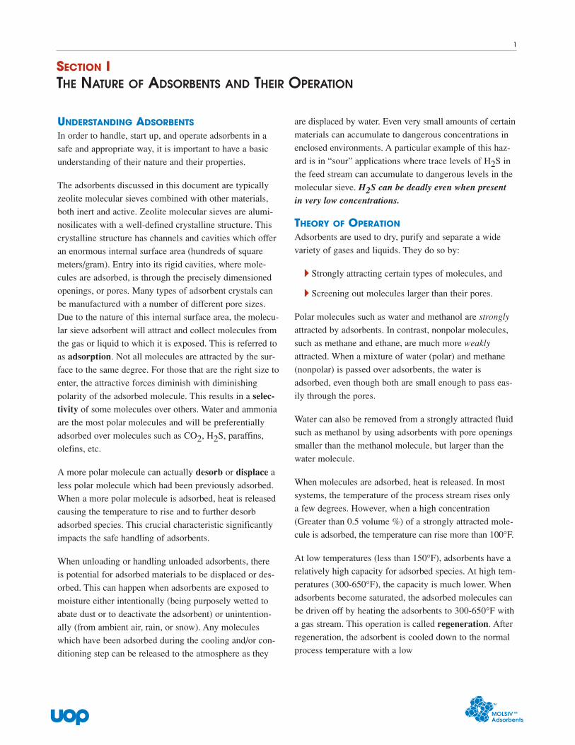
UNDERSTANDING ADSORBENTSIn order to handle, start up, and operate adsorbents in a
safe and appropriate way, it is important to have a basic
understanding of their nature and their properties.
The adsorbents discussed in this document are typically
zeolite molecular sieves combined with other materials,
both inert and active. Zeolite molecular sieves are alumi-
nosilicates with a well-defined crystalline structure. This
crystalline structure has channels and cavities which offer
an enormous internal surface area (hundreds of square
meters/gram). Entry into its rigid cavities, where mole-
cules are adsorbed, is through the precisely dimensioned
openings, or pores. Many types of adsorbent crystals can
be manufactured with a number of different pore sizes.
Due to the nature of this internal surface area, the molecu-
lar sieve adsorbent will attract and collect molecules from
the gas or liquid to which it is exposed. This is referred to
as adsorption. Not all molecules are attracted by the sur-
face to the same degree. For those that are the right size to
enter, the attractive forces diminish with diminishing
polarity of the adsorbed molecule. This results in a selec-tivity of some molecules over others. Water and ammonia
are the most polar molecules and will be preferentially
adsorbed over molecules such as CO2, H2S, paraffins,
olefins, etc.
A more polar molecule can actually desorb or displace a
less polar molecule which had been previously adsorbed.
When a more polar molecule is adsorbed, heat is released
causing the temperature to rise and to further desorb
adsorbed species. This crucial characteristic significantly
impacts the safe handling of adsorbents.
When unloading or handling unloaded adsorbents, there
is potential for adsorbed materials to be displaced or des-
orbed. This can happen when adsorbents are exposed to
moisture either intentionally (being purposely wetted to
abate dust or to deactivate the adsorbent) or unintention-
ally (from ambient air, rain, or snow). Any molecules
which have been adsorbed during the cooling and/or con-
ditioning step can be released to the atmosphere as they
are displaced by water. Even very small amounts of certain
materials can accumulate to dangerous concentrations in
enclosed environments. A particular example of this haz-
ard is in “sour” applications where trace levels of H2S in
the feed stream can accumulate to dangerous levels in the
molecular sieve. H2S can be deadly even when presentin very low concentrations.
THEORY OF OPERATIONAdsorbents are used to dry, purify and separate a wide
variety of gases and liquids. They do so by:
� Strongly attracting certain types of molecules, and
� Screening out molecules larger than their pores.
Polar molecules such as water and methanol are strongly
attracted by adsorbents. In contrast, nonpolar molecules,
such as methane and ethane, are much more weakly
attracted. When a mixture of water (polar) and methane
(nonpolar) is passed over adsorbents, the water is
adsorbed, even though both are small enough to pass eas-
ily through the pores.
Water can also be removed from a strongly attracted fluid
such as methanol by using adsorbents with pore openings
smaller than the methanol molecule, but larger than the
water molecule.
When molecules are adsorbed, heat is released. In most
systems, the temperature of the process stream rises only
a few degrees. However, when a high concentration
(Greater than 0.5 volume %) of a strongly attracted mole-
cule is adsorbed, the temperature can rise more than 100°F.
At low temperatures (less than 150°F), adsorbents have a
relatively high capacity for adsorbed species. At high tem-
peratures (300-650°F), the capacity is much lower. When
adsorbents become saturated, the adsorbed molecules can
be driven off by heating the adsorbents to 300-650°F with
a gas stream. This operation is called regeneration. After
regeneration, the adsorbent is cooled down to the normal
process temperature with a low
SECTION ITHE NATURE OF ADSORBENTS AND THEIR OPERATION
uop
1
uop
temperature stream before returning to service. In some
applications, adsorbents are regenerated by reducing pres-
sure, rather than heating. Continuous operation is
maintained by cycling two or more vessels between
adsorption and regeneration.
Follow the precautions in Section II whenever loading
fresh adsorbent into a vessel. During the start-up and
operation of an adsorption system, follow the precautions
covered in Section III. In process units, adsorbents are
exposed to liquids or gases from which they pick up vari-
ous materials, some of which can be hazardous (i.e. H2S,
NH3, CO2, various hydrocarbon and sulfur-containing
compounds). Before opening a used adsorbent vessel to
the atmosphere, install appropriate blind flanges, and
remove any potentially hazardous materials, as detailed in
Section IV.
For general technical questions, contact your UOP repre-
sentative.
For 24-hour Product Safety Emergency Assistancecontact:
In USA: UOP 847.391.2123
CHEMTREC 800.424.9300
In Canada: CANUTEC 613.996.6666
In Europe: BIG 32 14 58.45.45
In other countries: CHEMTREC 202.483.7616
2
� Removing hazardous materials from the vessel prior
to entry
� Isolating the confined space from sources of haz-
ardous materials or energy by installing blind flanges
to inlet and outlet nozzles and decoupling pumps and
instrumentation
� Providing adequate ventilation to prevent accumula-
tion of flammable materials, combustible dusts, toxic
contaminants or an environment that is oxygen defi-
cient or excessive
� Testing for oxygen, flammable gas, and suspected
toxic materials prior to entering the vessel
� Using safety attendants outside the vessel to monitor
� Communicating with personnel in the confined space
� Having notification and response procedures in place
for emergency situations such as injury or loss of
consciousness to personnel within the confined space
� Equipping personnel entering the vessel with the
appropriate safety equipment, this may require use of
safety harnesses and/or self-contained breathing
apparatus (SCBA)
� Training personnel authorized to work as safety
attendants, rescue personnel or persons entering the
confined space
� Conducting pre-job discussions with personnel
involved with the work about the potential hazards in
the confined space
LOADINGAdsorbents are normally shipped in 55-gallon sealed
drums or 35-50 cubic-foot bags. A vacuum may exist inside
the removable-top drums. First, loosen the vent screw on the
lid and break the vacuum. Then remove the top.
Take care when moving adsorbent containers. Proper lift-
ing techniques and equipment should be used. Full drums
weigh more than 300 pounds; full bags more than 2,100
SECTION IILOADING FRESH ADSORBENT
uop
3
Read and understand this section thoroughly before
loading fresh adsorbent. Observe all shipping container
precaution labels. Make sure that the product Material
Safety Data Sheet is available at the work site and
reviewed prior to handling the product.
PREPARATIONAdsorbents are typically supplied as pellets, beads or
granules. In their fresh, unused state, adsorbents present
minimal risk when appropriate protective equipment is
used. Appropriate protective equipment includes gloves,
long sleeve shirts and pants or coveralls to protect against
skin exposure; safety glasses, goggles or face shield to
protect the eyes; and dust masks or respirators if it is
expected that dust will be generated. When exposed to
water, the heat of adsorption can cause adsorbents to get
quite hot. Care should be taken to avoid contact withmoist skin, mucous membranes and eyes.
Note: Some special adsorbents may contain toxic orflammable materials. These adsorbents will have specialprecautions on the labels of the shipping containers andin the Material Safety Data Sheets. In such cases,always follow the special precautions provided by UOP.
If flammable vapors such as hydrocarbons are present in
the loading area, grounding is especially important to
avoid discharge of static electricity that could cause an
explosion or fire. Even conductive footwear and conduc-
tive walking surfaces may not prevent electrostatic buildup
on the human body. For example, removal of outer gar-
ments in low humidity conditions can generate sparks.
CONFINED SPACESIf entry to the vessel is required, confined space safe work
practices must be followed. Many countries have specific
regulations on confined space work. Personnel should
review these regulations and ensure that they are fol-
lowed. Among the precautions and practices that are
called for are:
uop
pounds. During loading, the containers must normally be
lifted to the top of the vessel. Sometimes, several drums
are dumped into a large hopper and this is lifted. This
activity requires that standard elevated work practices be
used, such as isolating the area under the lifting path and
using ropes or posting signs and keeping personnel clear
of the area.
Occasionally, pneumatic trucks are used to transfer adsor-
bent into the vessel through a hose. Keep the hose outlet
pointed away from personnel. Static electricity can build
up during transfer operations. Therefore make sure that
the transfer and receiving system are electrically grounded
to help dissipate any static charge.
4
3. Using a highly reactive fluid to heat or cool the bed.
(Examples of reactive fluids would include ethylene,
propylene and other olefins.)
INITIAL EXPOSURE TO A PROCESS STREAMGuidelines to avoid temperature excursions:
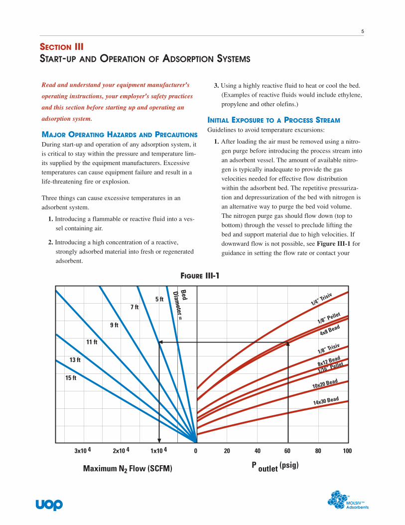
1. After loading the air must be removed using a nitro-
gen purge before introducing the process stream into
an adsorbent vessel. The amount of available nitro-
gen is typically inadequate to provide the gas
velocities needed for effective flow distribution
within the adsorbent bed. The repetitive pressuriza-
tion and depressurization of the bed with nitrogen is
an alternative way to purge the bed void volume.
The nitrogen purge gas should flow down (top to
bottom) through the vessel to preclude lifting the
bed and support material due to high velocities. If
downward flow is not possible, see Figure III-1 for
guidance in setting the flow rate or contact your
SECTION IIISTART-UP AND OPERATION OF ADSORPTION SYSTEMS
uop
5
1/4” Trisiv
1/8” Pellet
4x8 Bead
1/8” Trisiv
8x12 Bead
1/16” Pellet
10x20 Bead
14x30 Bead
15 ft
13 ft
11 ft
9 ft
7 ft5 ft
Diameter =
Bed
3x10 4 2x10 4 1x10 4 0 20 40 60 80 100
P outlet (psig)Maximum N2 Flow (SCFM)
FIGURE III-1
Read and understand your equipment manufacturer's
operating instructions, your employer's safety practices
and this section before starting up and operating an
adsorption system.
MAJOR OPERATING HAZARDS AND PRECAUTIONSDuring start-up and operation of any adsorption system, it
is critical to stay within the pressure and temperature lim-
its supplied by the equipment manufacturers. Excessive
temperatures can cause equipment failure and result in a
life-threatening fire or explosion.
Three things can cause excessive temperatures in an
adsorbent system.
1. Introducing a flammable or reactive fluid into a ves-
sel containing air.
2. Introducing a high concentration of a reactive,
strongly adsorbed material into fresh or regenerated
adsorbent.
uop
UOP representative for specific recommendations
for your unit. Continue purging until the oxygen
content of the outlet mixture is less than 0.5 volume %.
2. Do not introduce reactive, strongly adsorbed fluids
(such as ethylene, propylene and other olefins) into a
fresh or regenerated bed without proper preparation.
The heat of adsorption can increase the temperature
sufficiently to start a self-sustaining, heat-releasing
reaction. If unchecked, the temperatures can increase
enough to rupture the vessel and create a life-threat-
ening situation. For these systems, always use the
special procedures provided by the adsorbent sup-
plier in the process design. These procedures involve
exposing a fresh or regenerated bed to an inert
stream such as nitrogen to which a low concentra-
tion of the reactive fluid is added. The concentration
of the reactive fluid is slowly increased until the out-
let temperature drops back down and approaches the
inlet temperature. If the process stream is ethylene,
refer to the UOP Bulletin, entitled, Safe Practicesfor use of Molecular Sieves in EthylenePurification.
3. Do not use extremely reactive fluids to heat or cool a
bed. The elevated temperatures during regeneration
could start a hazardous heat-releasing reaction.
4. Never change the regeneration gas or feed stream
specified in the process design to another fluid with-
out first consulting with your UOP representative.
Such a change could create the hazardous conditions
discussed in items 2 and 3 above.
Complete the introduction of the reactive fluid and bring
the vessel up to normal operating pressure. Establish nor-
mal flow and closely monitor any intermediate and outlet
temperature indicators until each bed has completed one
adsorption step. If a readily adsorbed component in the
process stream is present at more than 0.5 volume %, both
temperatures will rise. However, if either temperature
rises more than 150°F above the inlet temperature, stopthe process immediately. This condition indicates that a
heat-releasing reaction may have started.
HEAT RELEASING REACTIONIn the event of a heat releasing reaction, stop it by taking
the following steps:
1. Close the valves on the lines leading into and out of
the vessels to stop the flow of fluid into the adsorbent.
2. Open the valve on the flare line to vent the bulk
of the reactants from the vessel to the flare for
combustion.
3. Purge with nitrogen to the flare to remove the
remaining reactants and cool the bed.
4. Contact UOP for assistance.
When one adsorption step is completed on each bed
without excess temperature rise, the system is ready for
normal processing.
REGENERATIONOnce the adsorbent bed is saturated, it is no longer effec-
tive and must be regenerated. This is normally done by
passing a gas stream over the adsorbent at 300-650°F.
The actual temperature is set by the design of the unit.
Because of heat losses, the bed outlet temperature should
always be lower than the temperature of the inlet during
heating. If the outlet temperature starts to increase above
the inlet temperature, stop the heating step immediately.This condition indicates that a heat-releasing reaction may
be occurring. Close the inlet and outlet valves to the ves-
sel being heated, depressurize it to the flare, and purge it
with nitrogen. Contact UOP for assistance.
During regeneration, the adsorbent bed may be as hot as
650°F. Always check the cooling outlet temperature after
regeneration to ensure the bed is cool before exposing it
to the feed stream. Failure to cool the bed before return-
ing it to service could result in downstream equipmentdamage or possibly initiate a heat-releasing reaction in
the case of reactive feed streams. Both consequences can
create a safety hazard. The adsorbent has high heat capac-
ity and low thermal conductivity. It can stay hot for weeks
if a shutdown occurs before the bed has been completely
cooled. For systems with automatic switching, always
check following a shutdown to ensure that a hot bed is
not switched from cooling prematurely.
6
1. Regenerate the bed: heat and cool it with a gas. If the
gas normally used to regenerate the bed is unavail-
able or contains toxic components at hazardous
levels, use nitrogen or an alternative nontoxic gas.
Your UOP molecular sieve representative will help
select an alternate gas and determine the proper flow
rate, temperature and pressure.
2. Completely cool the bed with gas, then isolate the
vessel and depressurize it. Install blind flanges on all
inlet and outlet lines except the flare line. Connect a
nitrogen source at the opposite end of the vessel.
3. The amount of available nitrogen is typically inade-
quate to provide the gas velocities needed for
effective flow distribution within the adsorbent bed.
The repetitive pressurization and depressurization of
the bed with nitrogen is an alternative way to purge
the bed void volume. The nitrogen purge gas should
be downflow (top to bottom) through the vessel to
preclude lifting the bed and support material due to
high velocities. If downward flow is not possible,
see Figure III-1 for guidance in setting the flow rate
or contact your UOP representative for specific rec-
ommendations for your unit.
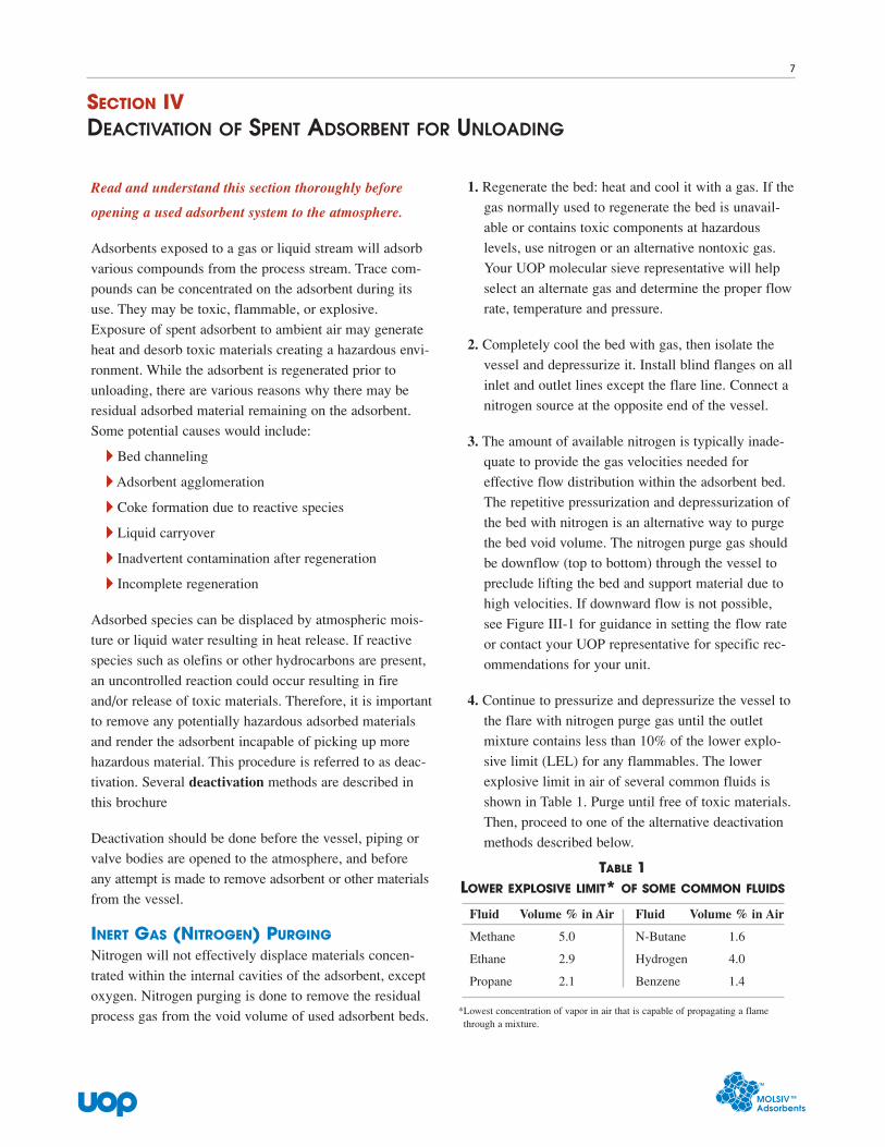
4. Continue to pressurize and depressurize the vessel to
the flare with nitrogen purge gas until the outlet
mixture contains less than 10% of the lower explo-
sive limit (LEL) for any flammables. The lower
explosive limit in air of several common fluids is
shown in Table 1. Purge until free of toxic materials.
Then, proceed to one of the alternative deactivation
methods described below.
SECTION IVDEACTIVATION OF SPENT ADSORBENT FOR UNLOADING
uop
7
Read and understand this section thoroughly before
opening a used adsorbent system to the atmosphere.
Adsorbents exposed to a gas or liquid stream will adsorb
various compounds from the process stream. Trace com-
pounds can be concentrated on the adsorbent during its
use. They may be toxic, flammable, or explosive.
Exposure of spent adsorbent to ambient air may generate
heat and desorb toxic materials creating a hazardous envi-
ronment. While the adsorbent is regenerated prior to
unloading, there are various reasons why there may be
residual adsorbed material remaining on the adsorbent.
Some potential causes would include:
� Bed channeling
� Adsorbent agglomeration
� Coke formation due to reactive species
� Liquid carryover
� Inadvertent contamination after regeneration
� Incomplete regeneration
Adsorbed species can be displaced by atmospheric mois-
ture or liquid water resulting in heat release. If reactive
species such as olefins or other hydrocarbons are present,
an uncontrolled reaction could occur resulting in fire
and/or release of toxic materials. Therefore, it is important
to remove any potentially hazardous adsorbed materials
and render the adsorbent incapable of picking up more
hazardous material. This procedure is referred to as deac-
tivation. Several deactivation methods are described in
this brochure
Deactivation should be done before the vessel, piping or
valve bodies are opened to the atmosphere, and before
any attempt is made to remove adsorbent or other materials
from the vessel.
INERT GAS (NITROGEN) PURGINGNitrogen will not effectively displace materials concen-
trated within the internal cavities of the adsorbent, except
oxygen. Nitrogen purging is done to remove the residual
process gas from the void volume of used adsorbent beds.
TABLE 1LOWER EXPLOSIVE LIMIT* OF SOME COMMON FLUIDS
Fluid Volume % in Air Fluid Volume % in Air
Methane 5.0 N-Butane 1.6
Ethane 2.9 Hydrogen 4.0
Propane 2.1 Benzene 1.4
*Lowest concentration of vapor in air that is capable of propagating a flamethrough a mixture.
uop
ADSORBENT DEACTIVATIONThere are several options for deactivating the spent adsor-
bent. All involve the saturation of the adsorbent with a
displacement fluid.
WATER FLOOD
Water is the preferred material for deactivating the adsor-
bent. Unlike nitrogen, water is more strongly attracted to
the adsorbent than nearly any of the potentially hazardous
materials which may be present. The simplest method is
to fill the bed from the bottom up with liquid water, after
preparing the adsorbent bed.
Note: Water flood should not be done without doing Step1(regeneration)below.
Important: This procedure renders the adsorbent unfitfor re-use. Furthermore, water flooding of an internallylined vessel may cause damage to the liner. Once wet,the liner is difficult to dry out.
1. Regenerate the bed: heat and cool it with a gas. If the
gas normally used to regenerate the bed is unavail-
able or contains toxic components at hazardous
levels, use nitrogen or an alternative nontoxic gas.
Your UOP molecular sieve representative will help
select an alternate gas and determine the proper flow
rate, temperature and pressure.
2. Completely cool the bed with gas, then isolate the
vessel and depressurize it. Install blind flanges on all
inlet and outlet lines except for the flare line at the
top of the vessel. Attach a water line to the bottom
of the vessel. Be sure that the water is obtained from
a safe and appropriate source and is compatible with
the equipment’s materials of construction.
3. As the vessel fills with water, displaced gases are
vented to the flare. To avoid overfilling the vessel
and flooding the flare line, monitor the water filling
rate and the liquid level. This can be easily done
with a properly calibrated DP indicator if one is
available. Alternatively, calibrated pressure gauges
can be temporarily mounted at the top and bottom of
the vessel. (Note: 14.7 psi is approximately equal to
34 ft of water.)
4. After the vessel is completely filled, shut off the line
to flare and open a vent port or vent valve to break
the vacuum on the vessel during draining. Then,
drain the water to an approved disposal location.
5. Pressurize the vessel with nitrogen and establish suf-
ficient flow to allow gas monitoring to ensure the
outlet of the vessel is below 10% of the LEL and is
free of toxic materials. If the nitrogen leaving the
vessel is not less than 10% LEL or contains toxic
materials, repeat the water flood procedure and gas
monitoring until these results are achieved.
WATER VAPOR DEACTIVATION
There are several drawbacks to the water flood procedure.
Internal vessel liners (if present) can be damaged, the
adsorbent cannot be reused, the waste water must be
expelled, residual liquid water must be completely
removed in water-sensitive applications (i.e. cryogenic or
turbo-expander facilities).
The following procedure avoids most of the problems
associated with the use of liquid water. However, it
requires the use of nitrogen as a carrier fluid for vaporized
and entrained liquid water.
1. Regenerate the bed: heat and cool it with a gas. If the
gas normally used to regenerate the bed is unavail-
able or contains toxic components at hazardous
levels, use nitrogen or an alternative nontoxic gas.
Your UOP molecular sieve representative will help
select an alternate gas and determine the proper flow
rate, temperature and pressure.
2. Completely cool the bed with gas, then isolate the
vessel and depressurize it. Install blind flanges on all
inlet and outlet lines except the flare line. Connect a
nitrogen source at the opposite end of the vessel.
3. Start a flow of nitrogen at the highest rate possible.
Introduce water into the nitrogen purge (carrier) gas
by either a) the injection of steam through a restrict-
ing orifice, or b) the injection of liquid water with a
metering pump and atomizer. Nitrogen saturated
with water vapor will generally not contain enough
water to allow for complete deactivation of the
adsorbent bed within an acceptable time frame. Most
8
uop
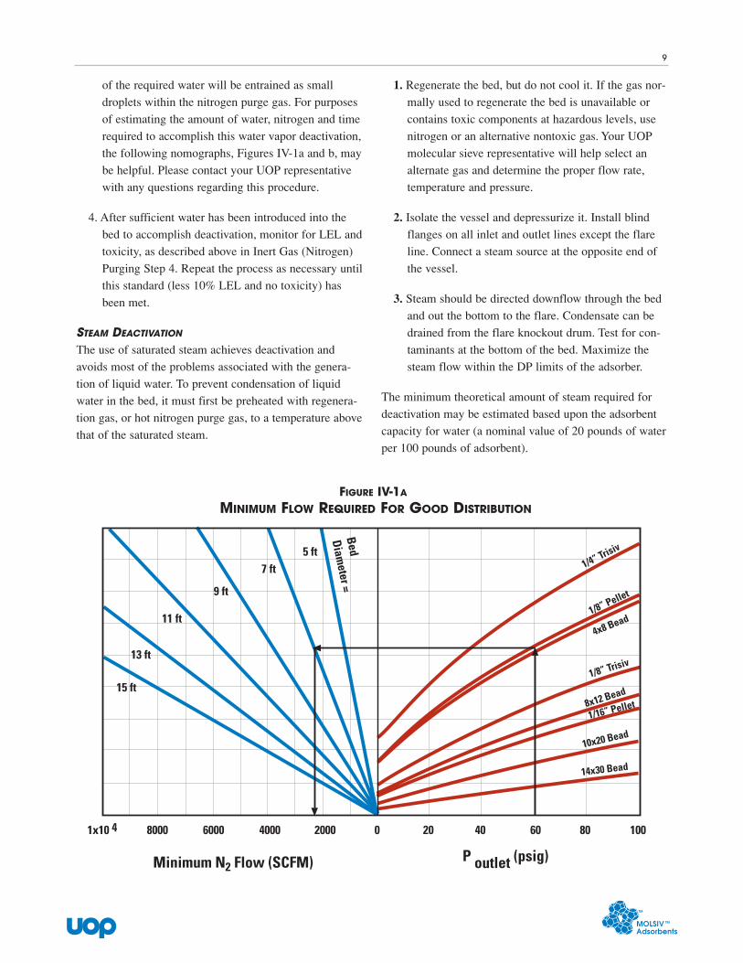
of the required water will be entrained as small
droplets within the nitrogen purge gas. For purposes
of estimating the amount of water, nitrogen and time
required to accomplish this water vapor deactivation,
the following nomographs, Figures IV-1a and b, may
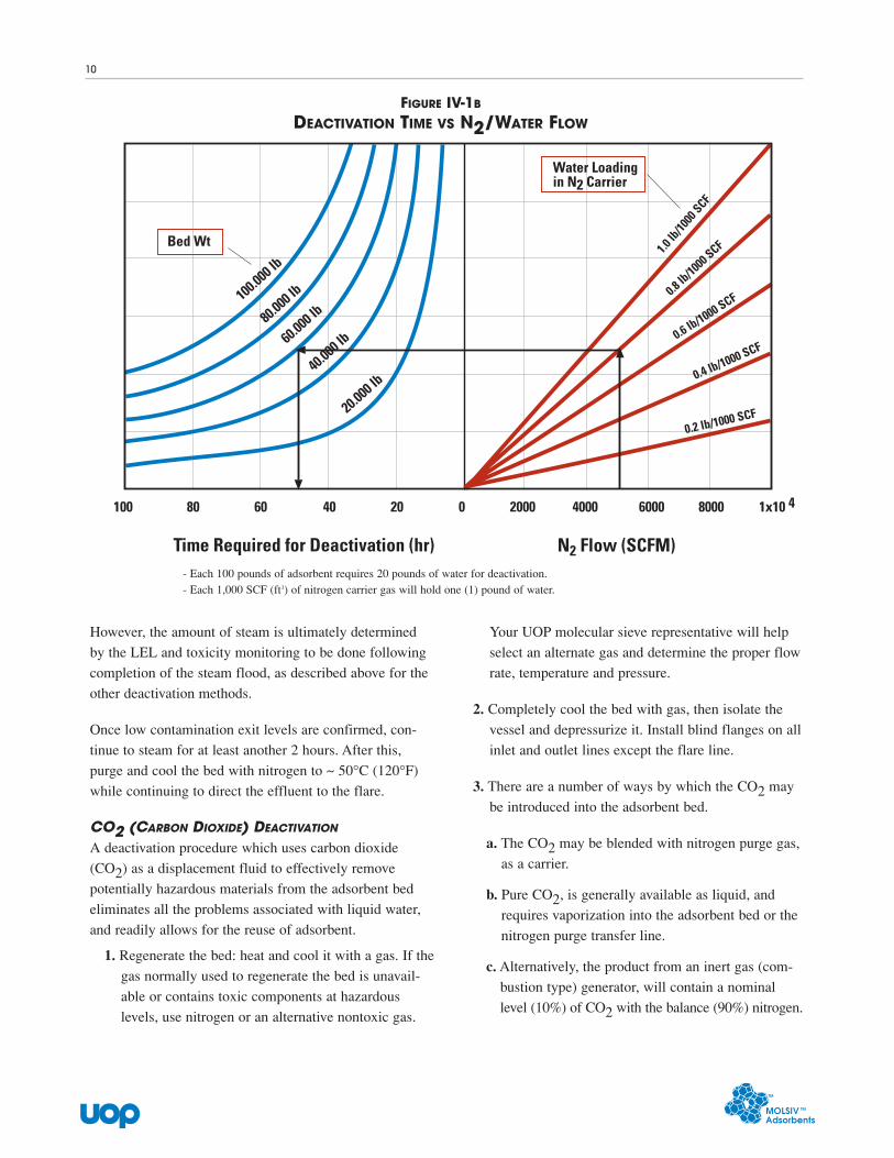
be helpful. Please contact your UOP representative
with any questions regarding this procedure.
4. After sufficient water has been introduced into the
bed to accomplish deactivation, monitor for LEL and
toxicity, as described above in Inert Gas (Nitrogen)
Purging Step 4. Repeat the process as necessary until
this standard (less 10% LEL and no toxicity) has
been met.
STEAM DEACTIVATION
The use of saturated steam achieves deactivation and
avoids most of the problems associated with the genera-
tion of liquid water. To prevent condensation of liquid
water in the bed, it must first be preheated with regenera-
tion gas, or hot nitrogen purge gas, to a temperature above
that of the saturated steam.
1. Regenerate the bed, but do not cool it. If the gas nor-
mally used to regenerate the bed is unavailable or
contains toxic components at hazardous levels, use
nitrogen or an alternative nontoxic gas. Your UOP
molecular sieve representative will help select an
alternate gas and determine the proper flow rate,
temperature and pressure.
2. Isolate the vessel and depressurize it. Install blind
flanges on all inlet and outlet lines except the flare
line. Connect a steam source at the opposite end of
the vessel.
3. Steam should be directed downflow through the bed
and out the bottom to the flare. Condensate can be
drained from the flare knockout drum. Test for con-
taminants at the bottom of the bed. Maximize the
steam flow within the DP limits of the adsorber.
The minimum theoretical amount of steam required for
deactivation may be estimated based upon the adsorbent
capacity for water (a nominal value of 20 pounds of water
per 100 pounds of adsorbent).
9
1/4” Trisiv
1/8” Pellet
4x8 Bead
1/8” Trisiv
8x12 Bead
1/16” Pellet
10x20 Bead
14x30 Bead
15 ft
13 ft
11 ft
9 ft
7 ft5 ft
Diameter =
Bed
1x10 4 8000 0 20 40 60 80 100
P outlet (psig)Minimum N2 Flow (SCFM)
6000 4000 2000
FIGURE IV-1A
MINIMUM FLOW REQUIRED FOR GOOD DISTRIBUTION
uop
However, the amount of steam is ultimately determined
by the LEL and toxicity monitoring to be done following
completion of the steam flood, as described above for the
other deactivation methods.
Once low contamination exit levels are confirmed, con-
tinue to steam for at least another 2 hours. After this,
purge and cool the bed with nitrogen to ~ 50°C (120°F)
while continuing to direct the effluent to the flare.
CO2 (CARBON DIOXIDE) DEACTIVATION
A deactivation procedure which uses carbon dioxide
(CO2) as a displacement fluid to effectively remove
potentially hazardous materials from the adsorbent bed
eliminates all the problems associated with liquid water,
and readily allows for the reuse of adsorbent.
1. Regenerate the bed: heat and cool it with a gas. If the
gas normally used to regenerate the bed is unavail-
able or contains toxic components at hazardous
levels, use nitrogen or an alternative nontoxic gas.
Your UOP molecular sieve representative will help
select an alternate gas and determine the proper flow
rate, temperature and pressure.
2. Completely cool the bed with gas, then isolate the
vessel and depressurize it. Install blind flanges on all
inlet and outlet lines except the flare line.
3. There are a number of ways by which the CO2 may
be introduced into the adsorbent bed.
a. The CO2 may be blended with nitrogen purge gas,
as a carrier.
b. Pure CO2, is generally available as liquid, and
requires vaporization into the adsorbent bed or the
nitrogen purge transfer line.
c. Alternatively, the product from an inert gas (com-
bustion type) generator, will contain a nominal
level (10%) of CO2 with the balance (90%) nitrogen.
10
1.0 lb
/1000
SCF
0.8 lb
/1000
SCF
0.6 lb/1000 SCF
0.4 lb/1000 SCF
0.2 lb/1000 SCF
100.00
0 lb
80 0 2000 4000 6000 8000 1x10 4
N2 Flow (SCFM)Time Required for Deactivation (hr)
60 40 20
Water Loadingin N2 Carrier
80.000
lb
60.000
lb
40.000
lb
20.000
lb
Bed Wt
100
FIGURE IV-1B
DEACTIVATION TIME VS N2/WATER FLOW
- Each 100 pounds of adsorbent requires 20 pounds of water for deactivation.- Each 1,000 SCF (ft3) of nitrogen carrier gas will hold one (1) pound of water.
uop
d. In a few instances, dry ice (solid CO2) can be
loaded on top of the adsorbent (under a nitrogen
blanket to avoid exposing the adsorbent to the
atmosphere). A flow of nitrogen purge carrier gas
will then be used to disperse the vaporizing CO2over the adsorbent.
4. Approximately 20 pounds of CO2 per 100 pounds of
adsorbent are required to deactivate the adsorbent
regardless of its means of delivery to the adsorber
vessel The determination of deactivation must be
based upon the results from monitoring this purge
gas from the bed, to ensure that it meets the stan-
dards of less than 10% LEL and no toxicity. If this
standard is not achieved, further CO2 displacement,
by repetitive pressurization and depressurization,
should be done. If, after repeating these steps, the
LEL and toxicity standards still cannot be met, then
another deactivation method should be used.
Note:
� If H2S is present on the adsorbent, CO2 will notdesorb it. In such case, the H2S will remain inadsorbent pores until a more polar compound, likewater, displaces it. If H2S is present, CO2 is notrecommended for deactivation.
� Inert gases such as CO2 and nitrogen can concen-trate in the pores of the adsorbent. Ambientmoisture can desorb these gases allowing them toconcentrate in enclosed spaces. The resultingatmosphere could be depleted in oxygen creating apersonnel hazard.
� Do not allow personnel to enter confined spacescontaining spent adsorbent without proper precau-tions.
KEY POINTS FOR DEACTIVATION OF ADSORBENT1. Regenerate with gas. If the gas you normally use to
regenerate the bed is unavailable or contains toxic
components at hazardous levels, use nitrogen or an
alternative nontoxic gas. Your UOP molecular sieve
representative will help you select an alternate gas
and determine the proper flow rate, temperature and
pressure.
2. Completely cool the bed with gas, then block-in the
vessel and depressurize it to the flare. Install blind
flanges on all vessel inlets and outlet lines except the
flare line. Install a nitrogen tap at the opposite end of
the vessel.
3. Select an appropriate deactivation fluid (in addition
to nitrogen) to effectively displace potentially haz-
ardous materials from the internal cavities of the
adsorbent bed. Establish a detailed procedure for
using this deactivation fluid.
Note: Both nitrogen and CO2, described in the aboveprocedures, presents a danger in and of themselves.Both gases are heavier than air, and both gases can leadto asphyxiation.
4. Continue the deactivation procedure until the outlet
gas from the adsorber vessel contains less than 10%
of the lower explosive limit (LEL) and is free of
toxic materials.
5. Particular care should be taken in applications where
the process streams contain H2S, COS, mercaptans
and other sulfur-based compounds – even if these
compounds are only present in minute quantities.
Inhalation or exposure to these products can befatal.
6. Contact your UOP representative with any questions
you may have regarding these procedures.
11
vessel. This can be done without entering the vessel.
Remove the loading port and secure the screen using a
harpoon-type tool.
Next, open the dump port and allow the adsorbent to flow
out. Once the adsorbent no longer flows out freely,
remove the remaining portion using a rake, hoe, shovel or
a vacuum truck. Never enter the vessel to remove theremaining adsorbent.
If at any time during unloading, materials on the adsor-bent start to burn or to react (as indicated by a largeheat release), stop unloading. Evacuate personnel from
the area. Properly trained personnel with self-contained
breathing apparatus can then return to stop the reaction or
put out the fire. To stop the reaction, or put out the fire,
use water from fire hoses to flood the adsorbent outside
the vessel. Contact UOP for assistance.
Note: Hazardous gases may be desorbed from the spentmaterial as a result of the heat release or fire, or as aresult of dousing the spent material with water.
Once all the adsorbent has been removed, prepare the
atmosphere in the vessel for safe entry. Remove the nitro-
gen purge line if used and attach an air mover so that air
is expelled out of the bottom of the vessel below the bed
support. The air will carry any remaining vapors out of
the vessel and away from the workers. Such vapors may
be released by adsorbent trapped under the bed support.
Extra care should be exercised for internally insulated
vessels. Hydrocarbon and toxic vapors may be slow to
outgas from the insulation. Leave the air mover on at all
times. Never use a plant air supply to purge the vesselwith air – a plant supply could become contaminated orbe hooked up to another source by mistake.
Once the actions have been completed to establish a safe
environment for vessel entry, personnel entering the ves-
sel must follow confined space work practices as outlined
in Section II.
uop
12
SECTION VUNLOADING AND HANDLING OF SPENT ADSORBENT
Read and understand this document thoroughly before
unloading used adsorbent.
PREPARATIONIt is important to maintain a nitrogen blanket on the vessel
during unloading regardless of what technique of adsor-
bent deactivation and purging is used in preparing the
adsorbent for unloading. Always assume that some haz-ardous and toxic materials remain on the adsorbent. Donot enter the vessel while the adsorbent remains inside.Hazardous materials may be released during unloading of
spent adsorbent creating a toxic, flammable or reactive
environment.
Be prepared for these situations. Limit access and contact
with spent sieve, have fire-fighting equipment available
and test the area around the unloaded sieve for flammable
or suspected toxic materials to establish whether you have
a safe environment. If monitoring or experience indicates
the environment may contain toxic materials in excess of
safe levels, use appropriate respiratory protection such as
respirators or self-contained breathing apparatus.
Note: UOP recommends that the spent adsorbent bedeactivated prior to unloading. Spent material that hasnot been fully deactivated could present a safety hazardby still containing toxic gases despite having beenregenerated prior to unloading. Furthermore, it couldpresent a safety hazard by having the potential to releasea significant amount of heat energy if it is wetted eitherwith hose water, rain or snow.
UNLOADINGContact with used adsorbent should be avoided. Workers
unloading the used adsorbent should wear gloves, long
sleeve shirts and pants or coveralls to protect against skin
exposure; safety glasses, goggles or face shields to protect
the eyes; and dust masks or respirators.
Normally, there is a stainless steel screen on top of the
adsorbent bed. Inert balls lie on top of the screen. To
make unloading easier, secure the screen to the top of the
uop
DISPOSALEither dispose of spent adsorbent immediately or store it
in a manner that will not impact the environment until
disposal can be arranged. It is recommended that spent
adsorbent be stored in containers such as drums or
portable luggers. If containers are not feasible, spent
adsorbent should be stored on an impermeable surface
such as concrete, asphalt or plastic sheeting that is heat
and chemical resistant. It is recommended that spent
adsorbent be protected from rainfall to prevent the possi-
bility of generating contaminated storm water runoff. If
water flooding has been used during unloading opera-
tions, additional spill prevention and controls such as
temporary dikes may be needed to contain free liquid that
may be generated when the spent adsorbent is unloaded.
In its fresh unused state, adsorbent is considered non-haz-
ardous for purposes of disposal. However the adsorbed
material on the spent adsorbent may change the classifica-
tion for purposes of disposal. Refer to national, state and
local regulations to determine proper disposal of spent
adsorbent. For any questions concerning disposal of used
adsorbent, contact your local UOP representative.
In summary, adsorbent can be handled and operated
safely if proper safety precautions are followed. If in
doubt about the safety of your adsorbent adsorption sys-
tem, please contact your local UOP representative.
KEY POINTS1. Prepare adsorbent using one of the recommended
procedures.
2. Limit access to the area.
3. Unload from outside the vessel.
4. Should reaction occur in the adsorbent during
unloading, stop unloading immediately.
5. Dispose of adsorbent immediately or store safely
until such time as it is possible.
13
IN CASE OF A MEDICAL OR FIREEMERGENCY RELATED TO UOPADSORBENTS, CALL +1-847-391-2123
UOP4273a 1003A5Ca
uopUOP LLC25 East Algonquin RoadDes Plaines, IL 60016-6101 U.S.A.www.uop.com
© 2003 UOP LLC. All rights reserved.