Embed Size (px)
Citation preview
PIM00132A
Proper use results in power saving
Inst
alla
tio
n
Pro
ced
ure
Bef
ore
O
per
atio
nU
sefu
l F
un
ctio
ns
Mai
nte
nan
ceTro
ubles
hoot
ingO
pti
on
al
Fu
nct
ion
sO
per
atin
g
Pro
ced
ure
Installation
ModelsMenu
Series
AKZJ188
AKZJ358
AKZJ458
AKZJ568
AKZJ908
Handling
Optional Parts
Maintenance
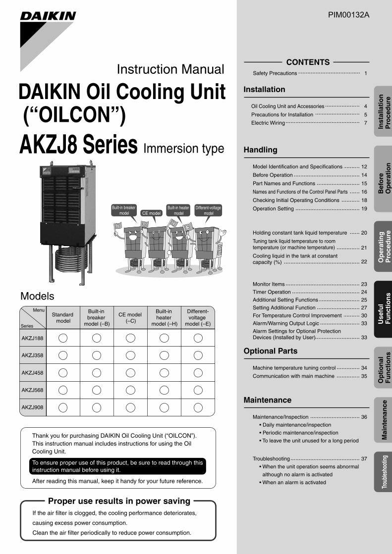
Immersion type
Instruction Manual
AKZJ8 Series
DAIKIN Oil Cooling Unit (“OILCON”)
Built-in breaker model
Different-voltage modelCE model
Built-in heater model
Standard model
Built-in breaker
model (–B)
CE model (–C)
Built-in heater
model (–H)
Different-voltage
model (–E)
If the air filter is clogged, the cooling performance deteriorates,
causing excess power consumption.
Clean the air filter periodically to reduce power consumption.
Thank you for purchasing DAIKIN Oil Cooling Unit (“OILCON”).This instruction manual includes instructions for using the Oil Cooling Unit.
To ensure proper use of this product, be sure to read through this instruction manual before using it.
After reading this manual, keep it handy for your future reference.
Before Operation
12Model Identification and Specifications
14
Part Names and Functions 15
Names and Functions of the Control Panel Parts 16
Checking Initial Operating Conditions 18
Operation Setting 19
Holding constant tank liquid temperature 20
Tuning tank liquid temperature to room temperature (or machine temperature) 21
Cooling liquid in the tank at constant capacity (%) 22
CONTENTS1Safety Precautions
Oil Cooling Unit and Accessories 4
Precautions for Installation 5
Electric Wiring 7
Monitor Items 23
Timer Operation 24
Additional Setting Functions 25
Setting Additional Function 27
For Temperature Control Improvement 30
Alarm/Warning Output Logic 33
Alarm Settings for Optional Protection Devices (Installed by User) 33
Machine temperature tuning control 34
36
37
Maintenance/Inspection
• Daily maintenance/inspection
• Periodic maintenance/inspection
• To leave the unit unused for a long period
Troubleshooting
• When the unit operation seems abnormal
although no alarm is activated
• When an alarm is activated
Communication with main machine 35
PIM00132A_EN.fm -1 ページ 2007年9月20日 木曜日 午後3時4分

PIM00132A_EN.fm 0 ページ 2007年9月20日 木曜日 午後3時4分
1
Mandatory Mandatory
Forbidden Ground cable connection
Mandatory
Forbidden
Forbidden
7
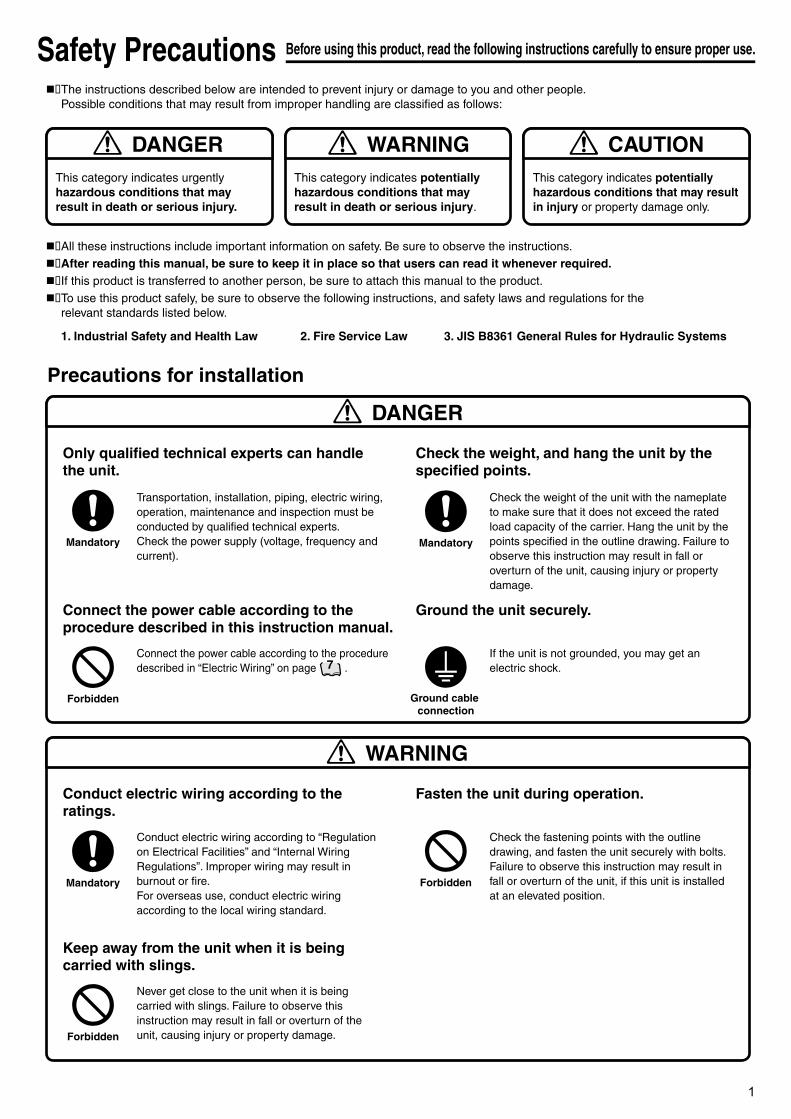
The instructions described below are intended to prevent injury or damage to you and other people.Possible conditions that may result from improper handling are classified as follows:
All these instructions include important information on safety. Be sure to observe the instructions.After reading this manual, be sure to keep it in place so that users can read it whenever required.If this product is transferred to another person, be sure to attach this manual to the product.To use this product safely, be sure to observe the following instructions, and safety laws and regulations for the relevant standards listed below.
Safety Precautions Before using this product, read the following instructions carefully to ensure proper use.
This category indicates urgently hazardous conditions that may result in death or serious injury.
DANGERThis category indicates potentially hazardous conditions that may result in death or serious injury.
WARNINGThis category indicates potentially hazardous conditions that may result in injury or property damage only.
CAUTION
Transportation, installation, piping, electric wiring, operation, maintenance and inspection must be conducted by qualified technical experts.Check the power supply (voltage, frequency and current).
DANGER
1. Industrial Safety and Health Law 2. Fire Service Law 3. JIS B8361 General Rules for Hydraulic Systems
Precautions for installation
Only qualified technical experts can handle the unit.
Connect the power cable according to the procedure described in “Electric Wiring” on page .
Connect the power cable according to the procedure described in this instruction manual.
Check the weight of the unit with the nameplate to make sure that it does not exceed the rated load capacity of the carrier. Hang the unit by the points specified in the outline drawing. Failure to observe this instruction may result in fall or overturn of the unit, causing injury or property damage.
Check the weight, and hang the unit by the specified points.
If the unit is not grounded, you may get an electric shock.
Ground the unit securely.
Conduct electric wiring according to “Regulation on Electrical Facilities” and “Internal Wiring Regulations”. Improper wiring may result in burnout or fire.For overseas use, conduct electric wiring according to the local wiring standard.
WARNING
Conduct electric wiring according to the ratings.
Never get close to the unit when it is being carried with slings. Failure to observe this instruction may result in fall or overturn of the unit, causing injury or property damage.
Keep away from the unit when it is being carried with slings.
Check the fastening points with the outline drawing, and fasten the unit securely with bolts. Failure to observe this instruction may result in fall or overturn of the unit, if this unit is installed at an elevated position.
Fasten the unit during operation.
PIM00132A_EN.fm 1 ページ 2007年9月20日 木曜日 午後3時4分
2
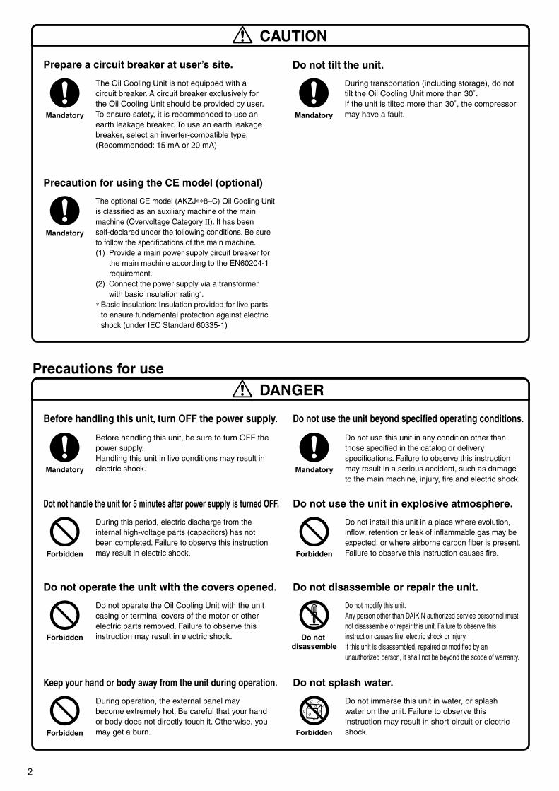
Before handling this unit, be sure to turn OFF the power supply.Handling this unit in live conditions may result in electric shock.
Precautions for use
Before handling this unit, turn OFF the power supply.
Do not operate the Oil Cooling Unit with the unit casing or terminal covers of the motor or other electric parts removed. Failure to observe this instruction may result in electric shock.
Do not operate the unit with the covers opened.
Do not use this unit in any condition other than those specified in the catalog or delivery specifications. Failure to observe this instruction may result in a serious accident, such as damage to the main machine, injury, fire and electric shock.
Do not use the unit beyond specified operating conditions.
Do not modify this unit.Any person other than DAIKIN authorized service personnel must not disassemble or repair this unit. Failure to observe this instruction causes fire, electric shock or injury.If this unit is disassembled, repaired or modified by an unauthorized person, it shall not be beyond the scope of warranty.
Do not disassemble or repair the unit.
Mandatory
Forbidden
During operation, the external panel may become extremely hot. Be careful that your hand or body does not directly touch it. Otherwise, you may get a burn.
Keep your hand or body away from the unit during operation.
Do not immerse this unit in water, or splash water on the unit. Failure to observe this instruction may result in short-circuit or electric shock.
Do not splash water.
Forbidden
During this period, electric discharge from the internal high-voltage parts (capacitors) has not been completed. Failure to observe this instruction may result in electric shock.
Dot not handle the unit for 5 minutes after power supply is turned OFF.
Do not install this unit in a place where evolution, inflow, retention or leak of inflammable gas may be expected, or where airborne carbon fiber is present. Failure to observe this instruction causes fire.
Do not use the unit in explosive atmosphere.
Forbidden
The Oil Cooling Unit is not equipped with a circuit breaker. A circuit breaker exclusively for the Oil Cooling Unit should be provided by user. To ensure safety, it is recommended to use an earth leakage breaker. To use an earth leakage breaker, select an inverter-compatible type. (Recommended: 15 mA or 20 mA)
Prepare a circuit breaker at user’s site.
Mandatory
The optional CE model (AKZJ∗∗8–C) Oil Cooling Unit is classified as an auxiliary machine of the main machine (Overvoltage Category II). It has been self-declared under the following conditions. Be sure to follow the specifications of the main machine.(1) Provide a main power supply circuit breaker for
the main machine according to the EN60204-1 requirement.
(2) Connect the power supply via a transformer with basic insulation rating∗.
∗ Basic insulation: Insulation provided for live parts to ensure fundamental protection against electric shock (under IEC Standard 60335-1)
Precaution for using the CE model (optional)
Mandatory
During transportation (including storage), do not tilt the Oil Cooling Unit more than 30˚. If the unit is tilted more than 30˚, the compressor may have a fault.
Do not tilt the unit.
Mandatory
Do not disassemble
Mandatory
Forbidden
Forbidden
CAUTION
DANGER
PIM00132A_EN.fm 2 ページ 2007年9月20日 木曜日 午後3時4分
3
Mandatory
Mandatory
Mandatory
Mandatory
Mandatory
Forbidden
Forbidden
Caution
Forbidden
Mandatory
Mandatory
Mandatory
Forbidden
Mandatory
Mandatory
Check
CAUTION
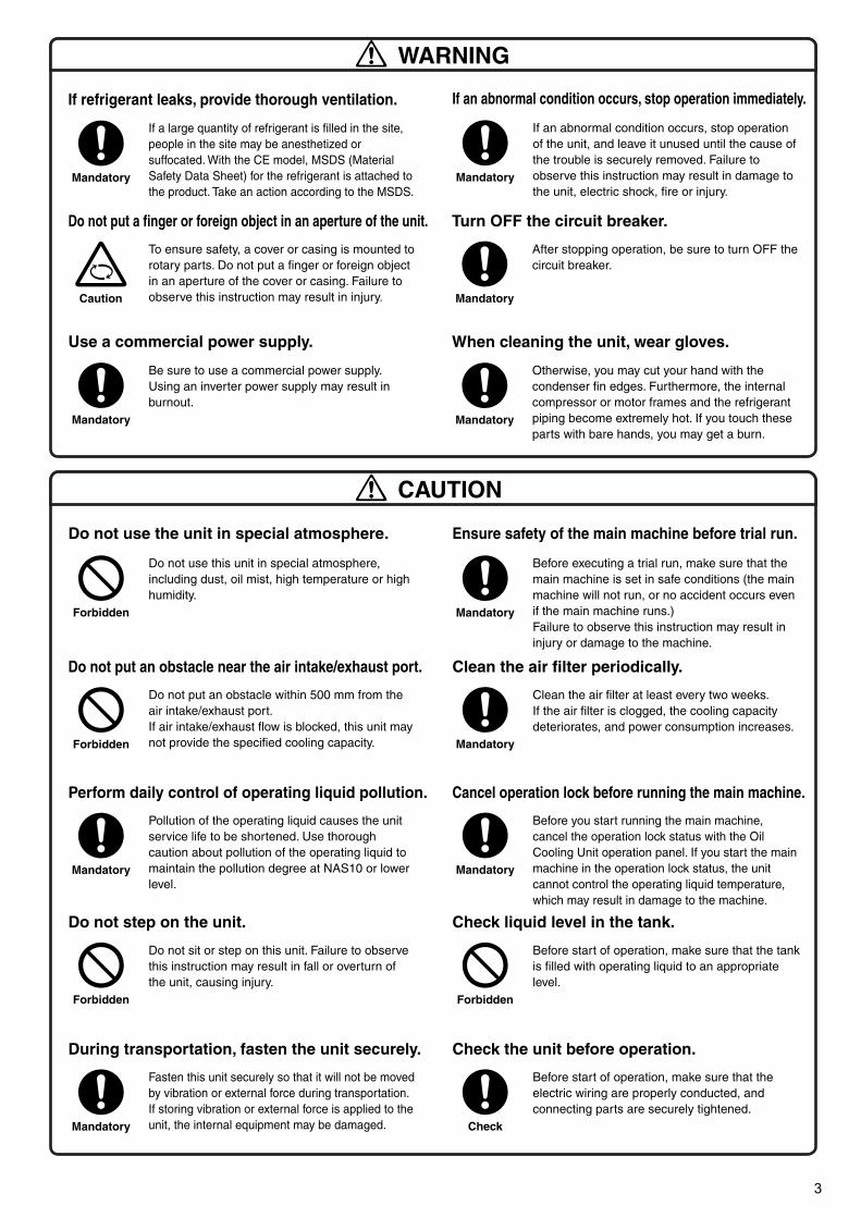
If a large quantity of refrigerant is filled in the site, people in the site may be anesthetized or suffocated. With the CE model, MSDS (Material Safety Data Sheet) for the refrigerant is attached to the product. Take an action according to the MSDS.
WARNING
If refrigerant leaks, provide thorough ventilation.
If an abnormal condition occurs, stop operation of the unit, and leave it unused until the cause of the trouble is securely removed. Failure to observe this instruction may result in damage to the unit, electric shock, fire or injury.
If an abnormal condition occurs, stop operation immediately.
Be sure to use a commercial power supply. Using an inverter power supply may result in burnout.
Use a commercial power supply.
To ensure safety, a cover or casing is mounted to rotary parts. Do not put a finger or foreign object in an aperture of the cover or casing. Failure to observe this instruction may result in injury.
Do not put a finger or foreign object in an aperture of the unit.
After stopping operation, be sure to turn OFF the circuit breaker.
Turn OFF the circuit breaker.
Pollution of the operating liquid causes the unit service life to be shortened. Use thorough caution about pollution of the operating liquid to maintain the pollution degree at NAS10 or lower level.
Perform daily control of operating liquid pollution.
Before you start running the main machine, cancel the operation lock status with the Oil Cooling Unit operation panel. If you start the main machine in the operation lock status, the unit cannot control the operating liquid temperature, which may result in damage to the machine.
Cancel operation lock before running the main machine.
Do not use this unit in special atmosphere, including dust, oil mist, high temperature or high humidity.
Do not use the unit in special atmosphere.
Before executing a trial run, make sure that the main machine is set in safe conditions (the main machine will not run, or no accident occurs even if the main machine runs.)Failure to observe this instruction may result in injury or damage to the machine.
Ensure safety of the main machine before trial run.
Do not put an obstacle within 500 mm from the air intake/exhaust port.If air intake/exhaust flow is blocked, this unit may not provide the specified cooling capacity.
Do not put an obstacle near the air intake/exhaust port.
Clean the air filter at least every two weeks.If the air filter is clogged, the cooling capacity deteriorates, and power consumption increases.
Clean the air filter periodically.
Do not sit or step on this unit. Failure to observe this instruction may result in fall or overturn of the unit, causing injury.
Do not step on the unit.
Before start of operation, make sure that the tank is filled with operating liquid to an appropriate level.
Check liquid level in the tank.
Fasten this unit securely so that it will not be moved by vibration or external force during transportation. If storing vibration or external force is applied to the unit, the internal equipment may be damaged.
During transportation, fasten the unit securely.
Before start of operation, make sure that the electric wiring are properly conducted, and connecting parts are securely tightened.
Check the unit before operation.
Otherwise, you may cut your hand with the condenser fin edges. Furthermore, the internal compressor or motor frames and the refrigerant piping become extremely hot. If you touch these parts with bare hands, you may get a burn.
When cleaning the unit, wear gloves.
PIM00132A_EN.fm 3 ページ 2007年9月20日 木曜日 午後3時4分
4
Inst
alla
tio
n
Pro
ced
ure
Inst
alla
tio
n
PIM00132
Proper use results in power saving
Inst
alla
tio
n
Pro
ced
ure
Bef
ore
O
per
atio
nU
sefu
l F
un
ctio
ns
Mai
nte
nan
ceTro
ubles
hoot
ingO
pti
on
al
Fu
nct
ion
sO
per
atin
g
Pro
ced
ure
Installation
ModelsMenu
Series
AKZJ188
AKZJ358
AKZJ458
AKZJ568
AKZJ908
Handling
Optional Parts
Maintenance
Immersion type
Instruction Manual
AKZJ8 Series
DAIKIN Oil Cooling Unit (“OILCON”)
Built-in breaker
model
Different-voltage
modelCE modelBuilt-in heater
model
Standard model
Built-in breaker
model (–B)
CE model (–C)
Built-in heater
model (–H)
Different-voltage
model (–E)
If the air filter is clogged, the cooling performance deteriorates,
causing excess power consumption.
Clean the air filter periodically to reduce power consumption.
Thank you for purchasing DAIKIN Oil Cooling Unit (“OILCON”).This instruction manual includes instructions for using the Oil Cooling Unit.
To ensure proper use of this product, be sure to read through this instruction manual before using it.
After reading this manual, keep it handy for your future reference.
Before Operation
12Model Identification and Specifications
14
Part Names and Functions 15
Names and Functions of the Control Panel Parts 16
Checking Initial Operating Conditions 18
Operation Setting 19
Holding constant tank liquid temperature 20
Tuning tank liquid temperature to room temperature (or machine temperature) 21
Cooling liquid in the tank at constant capacity (%) 22
CONTENTS1Safety Precautions
Oil Cooling Unit and Accessories 4
Precautions for Installation 5
Electric Wiring 7
Monitor Items 23
Timer Operation 24
Additional Setting Functions 25
Setting Additional Function 27
For Temperature Control Improvement 30
Alarm/Warning Output Logic 33
Alarm Settings for Optional Protection Devices (Installed by User) 33
Machine temperature tuning control 34
36
37
Maintenance/Inspection
• Daily maintenance/inspection
• Periodic maintenance/inspection
• To leave the unit unused for a long period
Troubleshooting
• When the unit operation seems abnormal
although no alarm is activated
• When an alarm is activated
Communication with main machine 35
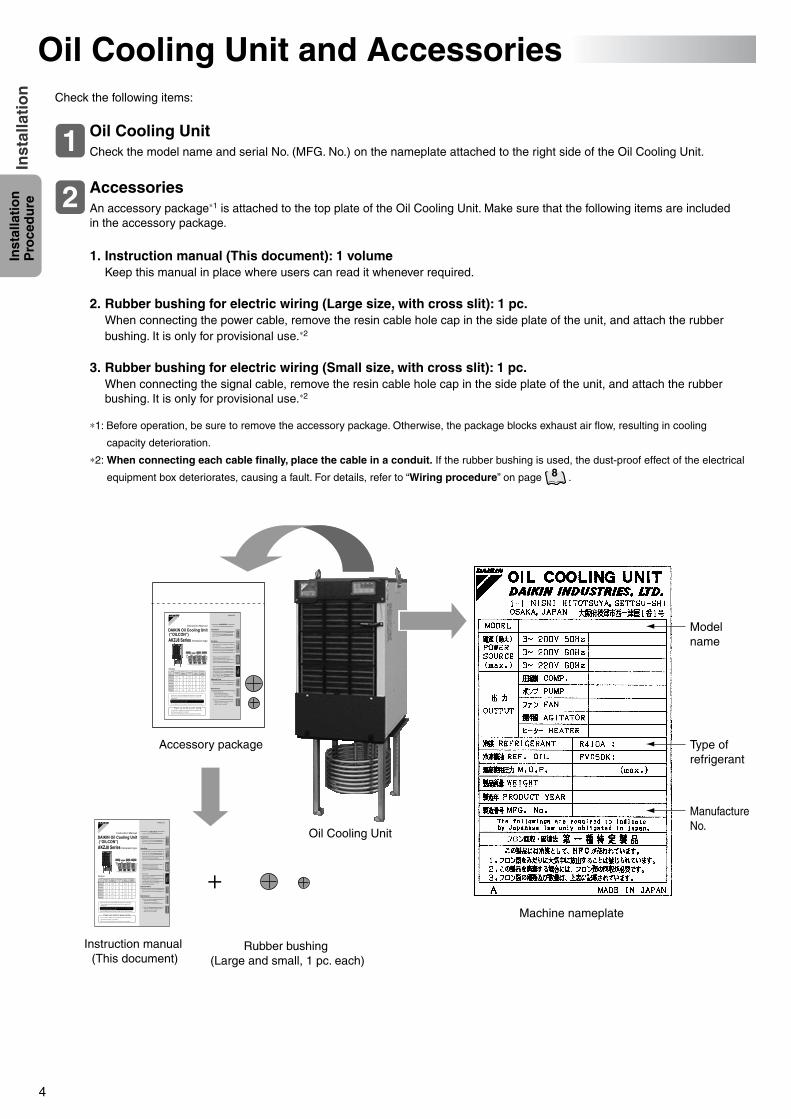
Oil Cooling Unit and AccessoriesCheck the following items:
Check the model name and serial No. (MFG. No.) on the nameplate attached to the right side of the Oil Cooling Unit.
Oil Cooling Unit1
An accessory package∗1 is attached to the top plate of the Oil Cooling Unit. Make sure that the following items are included in the accessory package.
Accessories2
+
Accessory package
Machine nameplate
Rubber bushing (Large and small, 1 pc. each)
Model name
Type of refrigerant
Manufacture No.
Oil Cooling Unit
1. Instruction manual (This document): 1 volumeKeep this manual in place where users can read it whenever required.
2. Rubber bushing for electric wiring (Large size, with cross slit): 1 pc.When connecting the power cable, remove the resin cable hole cap in the side plate of the unit, and attach the rubber bushing. It is only for provisional use.∗2
3. Rubber bushing for electric wiring (Small size, with cross slit): 1 pc.When connecting the signal cable, remove the resin cable hole cap in the side plate of the unit, and attach the rubber bushing. It is only for provisional use.∗2
∗1: Before operation, be sure to remove the accessory package. Otherwise, the package blocks exhaust air flow, resulting in cooling
capacity deterioration.
∗2: When connecting each cable finally, place the cable in a conduit. If the rubber bushing is used, the dust-proof effect of the electrical
equipment box deteriorates, causing a fault. For details, refer to “Wiring procedure” on page .8
Instruction manual (This document)
PIM00132A_EN.fm 4 ページ 2007年9月20日 木曜日 午後3時4分
5
Inst
alla
tio
n
Pro
ced
ure
Inst
alla
tio
n
Precautions for Installation
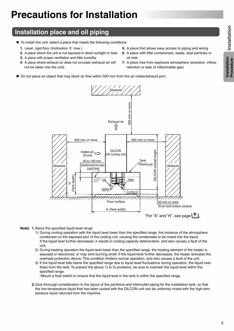
Note) 1.About the specified liquid level range1) During cooling operation with the liquid level lower than the specified range, the moisture of the atmosphere
condenses on the exposed part of the cooling coil, causing the condensate to be mixed into the liquid.If the liquid level further decreases, it results in cooling capacity deterioration, and also causes a fault of the unit.
2) During heating operation the liquid level lower than the specified range, the heating element of the heater is exposed or discolored, or may emit burning smell. If the liquid level further decreases, the heater activates the overheat protection device. This condition hinders normal operation, and also causes a fault of the unit.
3) If the liquid level falls below the specified range due to liquid level fluctuations during operation, the liquid over-flows from the tank. To prevent the above 1) to 3) problems, be sure to maintain the liquid level within the specified range.∗Mount a float switch to ensure that the liquid level in the tank is within the specified range.
2.Give thorough consideration to the layout of the partitions and inlet/outlet piping for the installation tank, so that the low-temperature liquid that has been cooled with the OILCON unit can be uniformly mixed with the high-tem-perature liquid returned from the machine.
Installation place and oil pipingTo install this unit, select a place that meets the following conditions:
Do not place an object that may block air flow within 500 mm from the air intake/exhaust port.
1. Level, rigid floor (Inclination: 5˚ max.)2. A place where the unit is not exposed to direct sunlight or heat3. A place with proper ventilation and little humidity4. A place where exhaust air does not circulate (exhaust air will
not be taken into the unit)
5. A place that allows easy access to piping and wiring6. A place with little contaminant, waste, dust particles or
oil mist7. A place free from explosive atmosphere (evolution, inflow,
retention or leak of inflammable gas)
Obstacle
Exhaust air
500
mm
or
mor
e
500 mm or more 500 mm or more
Intake air (Front)
Obstacle Obstacle
40 to 100 mm(Specified liquid level range)
Liquid level
Leg
H(T
ank
dept
h)
AgitatorCooling coil
Heater
Tank (Prepared by user)
OILCON (Oil cooling unit)
50 mm or more(From tank bottom surface)
OIL
CO
N o
vera
ll he
ight
Floor surface
A (Tank width)
*For “A” and “H”, see page .6
PIM00132A_EN.fm 5 ページ 2007年9月20日 木曜日 午後3時4分
6
Inst
alla
tio
n
Pro
ced
ure
Inst
alla
tio
n
10
mm2/s
10,00050,000
SUSSay
bolt
seco
nd
ISO
VG
Kine
mat
ic vis
cosit
y co
effic
ient
5,0003,0002,000
1,000
500400300200150
10075
5040
30
20
15
109.08.07.0
6.0
5.0
4.0
3.0
2.0
–10 0 10 20 30 40 50 60
–10 0 10 20 30 40 50 60 70˚C
20 30 40 50 60Temperature
70 80 90 100 110 120 130 140 150 ˚F
10 20 30 40 50 60Temperature
70 80 90 100 110 120 130 140 150 ˚F
30,00020,000
10,000
5,0003,0002,000
1,00068
46
32
22
10
5
2
500
300
200
150
100
80
60
50
45
40
35
(2)
(1)
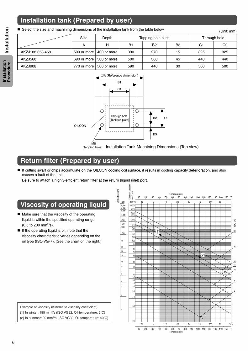
Size
A
500 or more
690 or more
770 or more
Depth
H
400 or more
500 or more
500 or more
B1
390
500
590
B2
270
380
440
B3
15
45
30
C1
325
440
500
C2
325
440
500
AKZJ188,358,458
AKZJ568
AKZJ908
Tapping hole pitch Through hole
Select the size and machining dimensions of the installation tank from the table below. (Unit: mm)
Through hole (Tank top plate)
OILCON
B1
B2
B3
C2
C1
4-M8Tapping hole
A (Reference dimension)
If cutting swarf or chips accumulate on the OILCON cooling coil surface, it results in cooling capacity deterioration, and also causes a fault of the unit.Be sure to attach a highly-efficient return filter at the return (liquid inlet) port.
Make sure that the viscosity of the operating liquid is within the specified operating range (0.5 to 200 mm2/s).
If the operating liquid is oil, note that the viscosity characteristic varies depending on the oil type (ISO VG∗∗). (See the chart on the right.)
Installation Tank Machining Dimensions (Top view)
Installation tank (Prepared by user)
Return filter (Prepared by user)
Viscosity of operating liquid
Example of viscosity (Kinematic viscosity coefficient)
(1) In winter: 195 mm2/s (ISO VG32, Oil temperature: 5˚C)
(2) In summer: 29 mm2/s (ISO VG32, Oil temperature: 40˚C)
PIM00132A_EN.fm 6 ページ 2007年9月20日 木曜日 午後3時4分
7
Inst
alla
tio
n
Pro
ced
ure
Inst
alla
tio
n
Coolant tank
Main machine (Machining center)
Power line
Circuit breaker
Power line
Signal
Main machine (Machining center)
Power line
Main machine (Machining center)
Circuit breaker
Remote control switch
Circuit breaker
Coolant tank
Control panel
Coolant tank
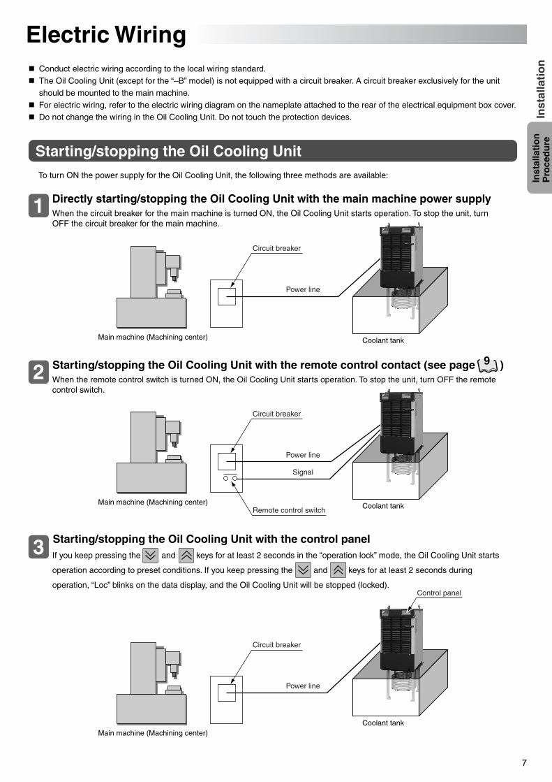
Electric WiringConduct electric wiring according to the local wiring standard.The Oil Cooling Unit (except for the “–B” model) is not equipped with a circuit breaker. A circuit breaker exclusively for the unit
should be mounted to the main machine.For electric wiring, refer to the electric wiring diagram on the nameplate attached to the rear of the electrical equipment box cover.Do not change the wiring in the Oil Cooling Unit. Do not touch the protection devices.
To turn ON the power supply for the Oil Cooling Unit, the following three methods are available:
Starting/stopping the Oil Cooling Unit
1
2
3
When the circuit breaker for the main machine is turned ON, the Oil Cooling Unit starts operation. To stop the unit, turn OFF the circuit breaker for the main machine.
Directly starting/stopping the Oil Cooling Unit with the main machine power supply
When the remote control switch is turned ON, the Oil Cooling Unit starts operation. To stop the unit, turn OFF the remote control switch.
Starting/stopping the Oil Cooling Unit with the remote control contact (see page )
If you keep pressing the and keys for at least 2 seconds in the “operation lock” mode, the Oil Cooling Unit starts
operation according to preset conditions. If you keep pressing the and keys for at least 2 seconds during
operation, “Loc” blinks on the data display, and the Oil Cooling Unit will be stopped (locked).
Starting/stopping the Oil Cooling Unit with the control panel
9
PIM00132A_EN.fm 7 ページ 2007年9月20日 木曜日 午後3時4分
8
Inst
alla
tio
n
Pro
ced
ure
Inst
alla
tio
n
Different-voltage model (–E)
Power cable insertion hole (φ28)
Top plate mounting screw
Top plate
Transformer box
For inside of the electrical equipment box, refer to the top view of the electrical equipment box in “Outline of electrical equipment box” (page ).9
To use an earth leakage breaker, select an inverter-compatible type.If the earth leakage breaker is not inverter-compatible, it may malfunction due to high-frequency noise of the inverter. (Recommended product: 15 mA or 20 mA)
(1) (4)
(3)
Different-voltage model (–E)
(2)
Standard model, –B, –C, –H
(2)
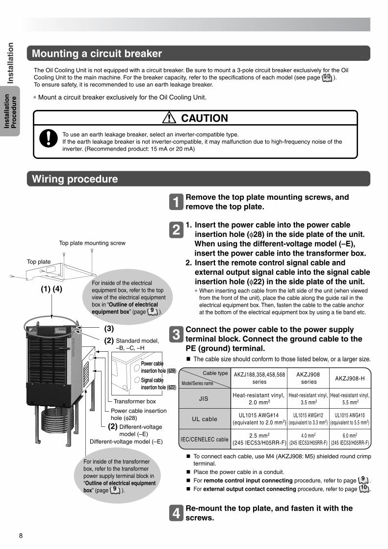
Mounting a circuit breaker
Wiring procedure
∗ Mount a circuit breaker exclusively for the Oil Cooling Unit.
The Oil Cooling Unit is not equipped with a circuit breaker. Be sure to mount a 3-pole circuit breaker exclusively for the Oil Cooling Unit to the main machine. For the breaker capacity, refer to the specifications of each model (see page ). To ensure safety, it is recommended to use an earth leakage breaker.
12·13
CAUTION
To connect each cable, use M4 (AKZJ908: M5) shielded round crimp terminal.
Place the power cable in a conduit.For remote control input connecting procedure, refer to page .For external output contact connecting procedure, refer to page .
Re-mount the top plate, and fasten it with the screws.4
910
Remove the top plate mounting screws, and remove the top plate.
1. Insert the power cable into the power cable insertion hole (φ28) in the side plate of the unit.When using the different-voltage model (–E), insert the power cable into the transformer box.
2. Insert the remote control signal cable and external output signal cable into the signal cable insertion hole (φ22) in the side plate of the unit.
Connect the power cable to the power supply terminal block. Connect the ground cable to the PE (ground) terminal.The cable size should conform to those listed below, or a larger size.
∗ When inserting each cable from the left side of the unit (when viewed from the front of the unit), place the cable along the guide rail in the electrical equipment box. Then, fasten the cable to the cable anchor at the bottom of the electrical equipment box by using a tie band etc.
1
2
3
Power cable insertion hole (f28)Power cable insertion hole (φ28)
Signal cable insertion hole (f22)Signal cable insertion hole (φ22)
For inside of the transformer box, refer to the transformer power supply terminal block in “Outline of electrical equipment box” (page ).9
AKZJ908 series AKZJ908-H
Model/Series name
Cable type AKZJ188,358,458,568series
Heat-resistant vinyl, 2.0 mm2
UL1015 AWG#14 (equivalent to 2.0 mm2)
2.5 mm2
(245 IEC53/H05RR-F)
Heat-resistant vinyl, 3.5 mm2
UL1015 AWG#12(equivalent to 3.3 mm2)
4.0 mm2
(245 IEC53/H05RR-F)
Heat-resistant vinyl, 5.5 mm2
UL1015 AWG#10(equivalent to 5.5 mm2)
6.0 mm2
(245 IEC53/H05RR-F)
JIS
UL cable
IEC/CENELEC cable
PIM00132A_EN.fm 8 ページ 2007年9月20日 木曜日 午後3時4分
9
Inst
alla
tio
n
Pro
ced
ure
Inst
alla
tio
n
OFF ON
Operation setting and parameter setting are enabled. (Standard factory setting)
Transformer power supply terminal block
For different-voltage model (–E) only
Alarm output
L1 L2 L3
Short-circuit bar
Control board
60 61 62 63 64 65 66 67 9 10 11 12 13 30 31
Operation setting and parameter setting cannot be changed.
Conducted by user
Temperature range warning output
Remote control input
For connection of optional protection device (OP)
For connection of machine temperature tuning sensor
No connection
No connection
CN2
(Ground terminal)
PROTECT SW
(Erroneous operation prevention)
Signal cable terminal block
Power supply terminal block
Top view
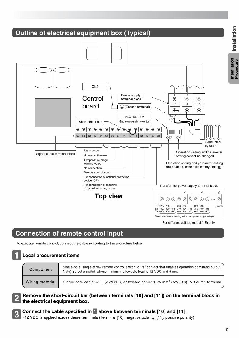
Outline of electrical equipment box (Typical)
Connection of remote control inputTo execute remote control, connect the cable according to the procedure below.
Local procurement items
ComponentSingle-pole, single-throw remote control switch, or “a” contact that enables operation command outputNote) Select a switch whose minimum allowable load is 12 VDC and 5 mA.
Single-core cable: φ1.2 (AWG16), or twisted cable: 1.25 mm2 (AWG16), M3 crimp terminalWiring material
1
E3:E2:E1:
Select a terminal according to the main power supply voltage.
415480
415480
415480440V 460 440 460 440 460
380V 400 380 400 380 400220V (Ground)220220230 230 230
WVU
Remove the short-circuit bar (between terminals [10] and [11]) on the terminal block in the electrical equipment box.
Connect the cable specified in above between terminals [10] and [11].∗12 VDC is applied across these terminals (Terminal [10]: negative polarity, [11]: positive polarity).
2
3 1
PIM00132A_EN.fm 9 ページ 2007年9月20日 木曜日 午後3時4分
10
Inst
alla
tio
n
Pro
ced
ure
Inst
alla
tio
n
60
61
63
60
61
63
60
61
63
60
61
63
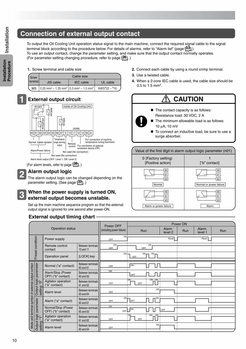
External output circuit
Alarm output logic
When the power supply is turned ON, external output becomes unstable.Set up the main machine sequence program so that the external output signal is ignored for one second after power-ON.
1
2
3
Connection of external output contact
2. Connect each cable by using a round crimp terminal.
3. Use a twisted cable.
4. When a 2-core IEC cable is used, the cable size should be 0.5 to 1.5 mm2.
60 61 62 63 64 65 66 67 9 10 11 12 13 30 31
RY30Y
RY
52P
AX
RY
30W
RY
30X
Temperature range warning
output
(X2M)
To output the Oil Cooling Unit operation status signal to the main machine, connect the required signal cable to the signal terminal block according to the procedure below. For details of alarms, refer to “Alarm list” (page ).To use an output contact, change the parameter setting, and make sure that the output contact normally operates. (For parameter setting changing procedure, refer to page .)26
38·39
1. Screw terminal and cable size
Cable size
UL cableIEC cable
M3 0.25 mm2 – 1.25 mm2 0.3 mm2 – 1.5 mm2 AWG#22 – #16
JIS cable
Screw terminal
The contact capacity is as follows:Resistance load: 30 VDC, 2 A
The minimum allowable load is as follows:10 µA, 10 mV
To connect an inductive load, be sure to use a surge absorber.
CAUTION
Normal Normal or power failure
Alarm or power failure Alarm
Value of the first digit in alarm output logic parameter (n01)
0 (Factory setting) [Positive action]
1[“b” contact]
Operation statusPower OFF
(including power failure)
Power ON
Run Run RunAlarm level 2
Alarm level 1
Power supply
Remote control contact
Operation panel
Normal (“a” contact)
Alarm/Stop (Power OFF) (“b” contact)
Agitator operation (“a” contact)
Alarm level
Alarm (“a” contact)
Normal/Stop (Power OFF) (“b” contact)
Between terminals 60 and 63
Between terminals 60 and 63
Agitator operation (“a” contact)
Alarm level
Between terminals 60 and 61
[LOCK] key
Between terminals 10 and 11
Between terminals 61 and 62
Between terminals 60 and 64
Between terminals 60 and 61
Between terminals 61 and 62
Between terminals 60 and 64
Pre
set c
ondi
tion
Out
put l
ogic
par
amet
er
setti
ng: “
0”
Mod
e an
d te
rmin
al s
ymbo
l of e
xter
nal o
utpu
t con
tact
Out
put l
ogic
par
amet
er
setti
ng: “
1”
OFF
OFF
OFF
ON
ON
OFF
OFF
ON
OFF
OFF
OFF
OFF
OFF
OFF
OFF
OFF
OFF
ON
ON
ON
ON
ON
ONON
ON
ON
OFF
ON ON
ON
ON
ON ON ON
OFF
ON
Reset Reset
External output timing chart
The alarm output logic can be changed depending on the parameter setting. (See page .)33
(For alarm levels, refer to page .)38
Inside of Oil Cooling Unit
Normal Agitator operation
Alarm/Power failure
Alarm level output (OFF: Level 1, ON: Level 2)
Not used (No connection)
Not used (No connection)
Remote control For connection of optional
protection device (OP)
For connection of machine temperature tuning thermistor
PIM00132A_EN.fm 10 ページ 2007年9月20日 木曜日 午後3時4分
11
Inst
alla
tio
n
Pro
ced
ure
Inst
alla
tio
n
A4P
A3P
Th–
5
Par
t sym
bol
Typ
e
AK
Z8
– O
P –
CS
P
AK
Z8
– O
P –
CS
AK
Z8
– O
P –
A10
AK
Z8
– O
P –
A5
AK
Z8
– O
P –
K10
AK
Z8
– O
P –
K5
(Opt
iona
l par
ts)
Nam
e
M1P
gro
und
Ele
ctric
hea
ter
Tra
nsfo
rmer
Ove
rhea
t pre
vent
ive
tem
pera
ture
sw
itch
Hig
h-pr
essu
re p
ress
ure
switc
h
No-
fuse
bre
aker
Com
pres
sor
prot
ectio
n th
erm
osta
t
Add
ition
al p
art s
ymbo
l
J1H
Mag
netic
con
tact
orH
1M
S3P
H
MC
CB
Tr
S2B
S4B
1
(Men
u m
odel
)
–E1,
E2,
E3
(Diff
eren
t-vo
ltage
mod
el)
Mod
el
–B (
Bui
lt-in
bre
aker
mod
el)
–C (
CE
mod
el)
–H (
Bui
lt-in
hea
ter)
(Sta
ndar
d)
EV
val
ve o
utle
t tem
pera
ture
ther
mis
tor
TH
01
Mai
n bo
ard
A1P
Fin
tem
pera
ture
ther
mis
tor
Th–
Fin
Exh
aust
gas
tem
pera
ture
ther
mis
tor
Th–
8
Con
dens
er te
mpe
ratu
re th
erm
isto
rT
h–7
Th–
6
Mot
or (
Fan
)M
3F
Agita
tor i
nner
ther
mos
tat
S1B
Fus
eF
U1–
5
Noi
se fi
lter
NF
Ope
ratio
n pa
nel b
oard
Con
nect
orC
N
Cap
acito
rC
1C
2C
3
Con
trol
box
tem
pera
ture
ther
mis
tor
Liqu
id te
mpe
ratu
re th
erm
isto
r
Air
(roo
m te
mpe
ratu
re)
ther
mis
tor
Mot
or (C
ompr
esso
r)M
2C
Rea
ctor
A2P
Ter
min
al b
lock
Ele
ctro
nic
expa
nsio
n va
lve
X1M
–X2M
Y1E
Th–
3
Mot
or (
Agi
tato
r)
Th–
4
M1K
L1
Not
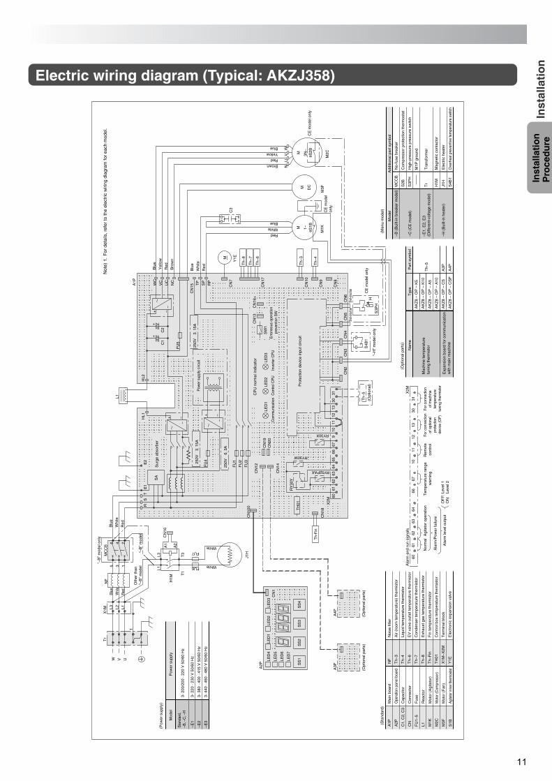
e) 1
.F
or d
etai
ls, r
efer
to th
e el
ectr
ic w
iring
dia
gram
for
each
mod
el.
For c
onne
ctio
n of
mac
hine
te
mpe
ratu
re
tuni
ng th
erm
isto
r
For c
onne
ctio
n of
opt
iona
l pr
otec
tion
devi
ce (O
P)
Rem
ote
cont
rol
ON
: L
evel
2O
FF
: Lev
el 1
X2M
Ala
rm le
vel o
utpu
t
Ala
rm/P
ower
failu
re
Agi
tato
r op
erat
ion
Nor
mal
Ala
rm a
nd r
un s
igna
ls
6061
6263
6466
6710
1112
1330
31
Tem
pera
ture
ran
ge
war
ning
Short
-circui
t bar
“–H
” m
odel
onl
y
Oth
er th
an
“–B
” m
odel
“–B
” m
odel
S4B
1
CE
mod
el
only
C3
M1KM 1– θS1B
Blue
Red
White
CN
16
T1
T3
L1L3
H1M
A1
A2
FU6
J1H
White
WhiteFU7
1
Tr
W V U246
(Opt
iona
l par
ts)
(Opt
iona
l par
ts)
A4P
A3P
Th-
Fin
TH
01
Com
mun
icat
ion
LED
1
250V
315
A
250V
63A
Y1EM
CN
18
CN
100
CN
19C
N20
CN
12
CN
14
LED
3
Inve
rter C
PU
LED
2
Con
trol C
PU
CP
U n
orm
al in
dica
tor
CN
16+
CN
13
Err
oneo
us o
pera
tion
prev
entio
n S
W
SW
1
FU
3
FU
2
FU
1
FU
4
SA
Sur
ge a
bsor
ber
E2
E1
TS
R
Pow
er s
uppl
y ci
rcui
t
––+
––+
L1
HL1
HL2
––+
++
C2
C1
FU
5
CN
15WC
NC
UC
VC
RP
SP
TP
Th–
8
Th–
7
Th–
6
Th–
3
Th–
4
Pro
tect
ion
devi
ce in
put c
ircui
t
RY30W
RY
30Y
RY52PAX
RY30X
6160
6263
6465
6667
910
1112
1330
31X
2M
CN
17
A1P
Red
Bro
wn
Blu
e
Yel
low
Red
Whi
te
Blu
e
Brown
NU
WV
Blue
Yellow
Red
CN
7
CN
8
CN
9
CN
10
CN
4C
N5
CN
6C
N3
CN
2
M3FM DC
M 3N–
A2P
LED
4
LED
5
LED
6
LED
7
LED
1LE
D2
LED
3C
N1
SS
1S
S2
SS
3S
S4
Blu
e
Whi
te
Red
Whi
te
Blu
e
Red
NF
MC
CB
35 1
θS2B
CE
mod
el o
nly
CE
mod
el o
nly
Short
-circui
t bar
H
S3P
H
“–B
” m
odel
onl
y
Th–
5
(Opt
iona
l)
250V
315
A
L2L3 L1
X1M
M2C
3- 4
40 ·
460
· 480
V 5
0/60
Hz
3- 3
80 ·
400
· 415
V 5
0/60
Hz
3- 2
20 ·
230
V 5
0/60
Hz
–E2
–E3
–E1
Sta
ndar
d,
–B, –
C, –
H3-
200
/200
· 22
0 V
50/
60 H
z
(Pow
er s
uppl
y)
Pow
er s
uppl
yM
odel
Mac
hine
tem
pera
ture
tu
ning
ther
mis
tor
Exp
ansi
on b
oard
for
com
mun
icat
ion
with
mai
n m
achi
ne
Electric wiring diagram (Typical: AKZJ358)
PIM00132A_EN.fm 11 ページ 2007年9月20日 木曜日 午後3時4分
12
Bef
ore
O
per
atio
nH
and
ling
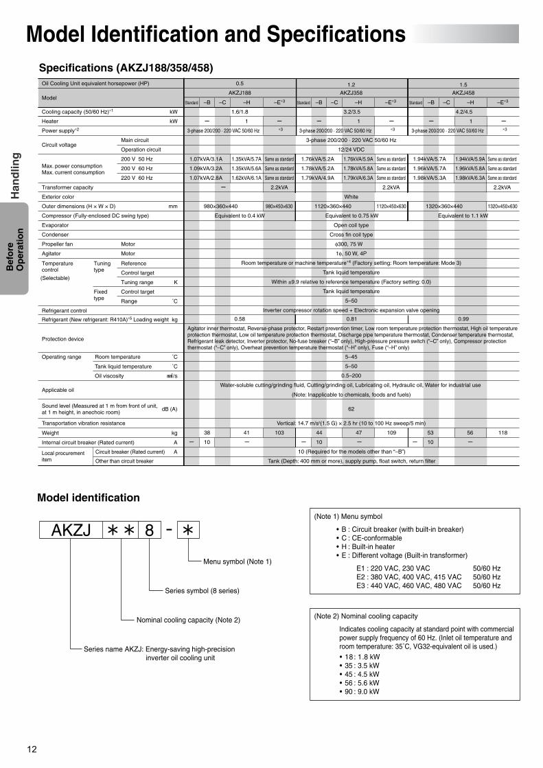
Model Identification and SpecificationsSpecifications (AKZJ188/358/458)
Model identification
AKZJ 8 -(Note 1) Menu symbol
• B : Circuit breaker (with built-in breaker)• C : CE-conformable• H : Built-in heater• E : Different voltage (Built-in transformer)
E1 : 220 VAC, 230 VAC 50/60 HzE2 : 380 VAC, 400 VAC, 415 VAC 50/60 HzE3 : 440 VAC, 460 VAC, 480 VAC 50/60 Hz
• 18 : 1.8 kW• 35 : 3.5 kW• 45 : 4.5 kW• 56 : 5.6 kW• 90 : 9.0 kW
(Note 2) Nominal cooling capacity
Indicates cooling capacity at standard point with commercial power supply frequency of 60 Hz. (Inlet oil temperature and room temperature: 35˚C, VG32-equivalent oil is used.)Series name AKZJ: Energy-saving high-precision
inverter oil cooling unit
Nominal cooling capacity (Note 2)
Series symbol (8 series)
Menu symbol (Note 1)
Oil Cooling Unit equivalent horsepower (HP) 0.5 1.5
1.6/1.8
AKZJ188 AKZJ458
1.35kVA/5.7A
1.35kVA/5.6A
1.62kVA/6.1A
Same as standard
Same as standard
Same as standard
1.07kVA/3.1A
1.09kVA/3.2A
1.07kVA/2.8A
Equivalent to 0.4 kW
–H –E∗3Standard
Cooling capacity (50/60 Hz)∗1 kW
kW
200 V 50 Hz
200 V 60 Hz
220 V 60 Hz
mm
K
˚C
˚C
˚C
kg
Heater
Power supply∗2
Transformer capacity
Exterior color
Outer dimensions (H × W × D)
Compressor (Fully-enclosed DC swing type)
Evaporator
Condenser
Propeller fan Motor
Refrigerant control
Local procurement item
Circuit breaker (Rated current)
Other than circuit breaker
Refrigerant (New refrigerant: R410A)∗5 Loading weight
Applicable oil
Protection device
Temperature control
Tuning type
Fixed type
Reference
Control target
Tuning range
Control target
Range
MotorAgitator
Max. power consumptionMax. current consumption
Main circuit
Operation circuitCircuit voltage
Model
(Selectable)
Operating range
Oil viscosity
Tank liquid temperature
Room temperature
Transportation vibration resistance
kgWeight
AInternal circuit breaker (Rated current)
A
–B –C
980×360×440 980×450×630
1034138
10 (Required for the models other than “–B”)
3-phase 200/200 · 220 VAC 50/60 Hz ∗3
3-phase 200/200 · 220 VAC 50/60 Hz
12/24 VDC
White
Open coil type
Cross fin coil type
1φ, 50 W, 4P
Room temperature or machine temperature∗4 (Factory setting: Room temperature: Mode 3)
Tank liquid temperature
Within ±9.9 relative to reference temperature (Factory setting: 0.0)
Tank liquid temperature
5–50
Inverter compressor rotation speed + Electronic expansion valve opening
5–45
5–50
0.5–200
Water-soluble cutting/grinding fluid, Cutting/grinding oil, Lubricating oil, Hydraulic oil, Water for industrial use
(Note: Inapplicable to chemicals, foods and fuels)
Vertical: 14.7 m/s2(1.5 G) × 2.5 hr (10 to 100 Hz sweep/5 min)
Agitator inner thermostat, Reverse-phase protector, Restart prevention timer, Low room temperature protection thermostat, High oil temperature protection thermostat, Low oil temperature protection thermostat, Discharge pipe temperature thermostat, Condenser temperature thermostat, Refrigerant leak detector, Inverter protector, No-fuse breaker (“–B” only), High-pressure pressure switch (“–C” only), Compressor protection thermostat (“–C” only), Overheat prevention temperature thermostat (“–H” only), Fuse (“–H” only)
2.2kVA
1.76kVA/5.9A
1.78kVA/5.8A
1.79kVA/6.3A
Same as standard
Same as standard
Same as standard
1.76kVA/5.2A
1.78kVA/5.2A
1.79kVA/4.9A
2.2kVA
1.94kVA/5.9A
1.96kVA/5.8A
1.98kVA/6.3A
Same as standard
Same as standard
Same as standard
1.94kVA/5.7A
1.96kVA/5.7A
1.98kVA/5.3A
2.2kVA
–H –E∗3Standard –B –C
1
φ300, 75 W
0.58 0.81 0.99
62
Tank (Depth: 400 mm or more), supply pump, float switch, return filter
10
1.2
AKZJ358
–H –E∗3Standard –B –C
3.2/3.5
3-phase 200/200 · 220 VAC 50/60 Hz ∗3
1
4.2/4.5
3-phase 200/200 · 220 VAC 50/60 Hz ∗3
1
1094744
10
1185653
10
Equivalent to 0.75 kW
1120×360×440 1120×450×630
Equivalent to 1.1 kW
1320×360×440 1320×450×630
Sound level (Measured at 1 m from front of unit, at 1 m height, in anechoic room)
dB (A)
PIM00132A_EN.fm 12 ページ 2007年9月20日 木曜日 午後3時4分
13
Bef
ore
O
per
atio
nH
and
ling
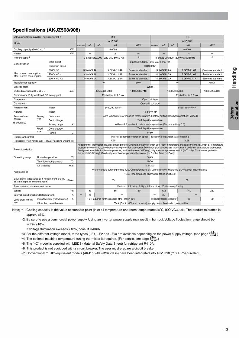
Specifications (AKJZ568/908)2.0 3.0
5.0/5.6 8.0/9.0
AKZJ568 AKZJ908
4.0kVA/11.4A
4.0kVA/11.4A
4.8kVA/12.5A
Same as standard
Same as standard
Same as standard
3.3kVA/9.4A
3.3kVA/9.4A
3.4kVA/9.0A
7.5kVA/21.6A
7.5kVA/21.6A
9.0kVA/23.7A
3.9kVA/11.2A
4.1kVA/11.7A
4.3kVA/11.2A
Same as standard
Same as standard
Same as standard
Equivalent to 1.5 kW Equivalent to 2.2 kW
–H –E∗3Standard –B –C
1450×470×500 1450×560×710 1630×560×620 1630×655×830
86 16083
15 (Required for the models other than “–B”) 20 (Required for the models other than “–B”) 30 20
140 220132
3-phase 200/200 · 220 VAC 50/60 Hz ∗3 3-phase 200/200 · 220 VAC 50/60 Hz
3-phase 200/200 · 220 VAC 50/60 Hz
DC12/24V
White
Open coil type
Cross fin coil type
1φ, 50 W, 4P
Room temperature or machine temperature∗4 (Factory setting: Room temperature: Mode 3)
Tank liquid temperature
Within ±9.9 relative to reference temperature (Factory setting: 0.0)
Tank liquid temperature
5–50
Inverter compressor rotation speed + Electronic expansion valve opening
5–45
5–50
0.5–200
Water-soluble cutting/grinding fluid, Cutting/grinding oil, Lubricating oil, Hydraulic oil, Water for industrial use
(Note: Inapplicable to chemicals, foods and fuels)
Vertical: 14.7 m/s2(1.5 G) × 2.5 hr (10 to 100 Hz sweep/5 min)
Agitator inner thermostat, Reverse-phase protector, Restart prevention timer, Low room temperature protection thermostat, High oil temperature protection thermostat, Low oil temperature protection thermostat, Discharge pipe temperature thermostat, Condenser temperature thermostat, Refrigerant leak detector, Inverter protector, No-fuse breaker (“–B” only), High-pressure pressure switch (“–C” only), Compressor protection thermostat (“–C” only), Overheat prevention temperature thermostat (“–H” only), Fuse (“–H” only)
∗3
5kVA 6kVA
–H –E∗3Standard –B –C
2 4
φ400, 90 W×4P φ450, 150 W×4P
1.25 1.65
65 68
Tank (Depth: 400 mm or more), supply pump, float switch, return filter
15 20
Oil Cooling Unit equivalent horsepower (HP)
Cooling capacity (50/60 Hz)∗1 kW
kW
200 V 50 Hz
200 V 60 Hz
220 V 60 Hz
mm
K
˚C
˚C
˚C
kg
Heater
Power supply∗2
Transformer capacity
Exterior color
Outer dimensions (H × W × D)
Compressor (Fully-enclosed DC swing type)
Evaporator
Condenser
Propeller fan Motor
Refrigerant control
Local procurement item
Circuit breaker (Rated current)
Other than circuit breaker
Refrigerant (New refrigerant: R410A)∗5 Loading weight
Applicable oil
Protection device
Temperature control
Tuning type
Fixed type
Reference
Control target
Tuning range
Control target
Range
MotorAgitator
Max. power consumptionMax. current consumption
Main circuit
Operation circuitCircuit voltage
Model
(Selectable)
Operating range
Oil viscosity
Tank liquid temperature
Room temperature
Transportation vibration resistance
kgWeight
AInternal circuit breaker (Rated current)
A
Sound level (Measured at 1 m from front of unit, at 1 m height, in anechoic room)
dB (A)
Note) ∗1: Cooling capacity is the value at standard point (inlet oil temperature and room temperature: 35˚C, ISO VG32 oil). The product tolerance is
approx. ±5%.
∗2: Be sure to use a commercial power supply. Using an inverter power supply may result in burnout. Voltage fluctuation range should be
within ±10%.
If voltage fluctuation exceeds ±10%, consult DAIKIN.
∗3: For the different-voltage model, three types (–E1, –E2 and –E3) are available depending on the power supply voltage. (see page .)
∗4: The optional machine temperature tuning thermistor is required. (For details, see page .)
∗5: The “–C” model is supplied with MSDS (Material Safety Data Sheet) for refrigerant R410A.
∗6: This product is not equipped with a circuit breaker. The user must prepare a circuit breaker.
∗7: Conventional “1 HP”-equivalent models (AKJ106/AKZJ287 class) have been integrated into AKZJ358 (“1.2 HP”-equivalent).
34
12
PIM00132A_EN.fm 13 ページ 2007年9月20日 木曜日 午後3時4分
14
Bef
ore
O
per
atio
nH
and
ling 50
40
45
30
20
10
5 10 20 30 40 50
5
Roo
m te
mpe
ratu
re
Tank liquid temperature (˚C)
(˚C)
Allowab
le op
erati
ng ra
nge
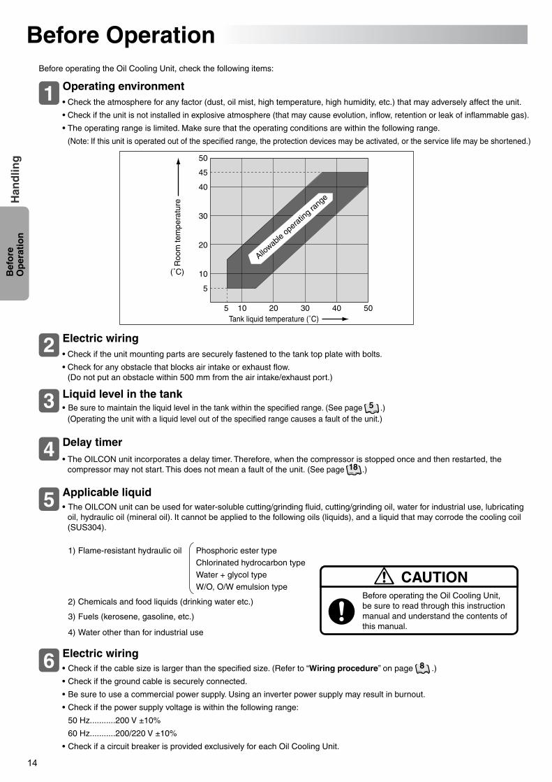
Electric wiring2• Check if the unit mounting parts are securely fastened to the tank top plate with bolts.
• Check for any obstacle that blocks air intake or exhaust flow. (Do not put an obstacle within 500 mm from the air intake/exhaust port.)
Applicable liquid5
Liquid level in the tank
Delay timer
3 • Be sure to maintain the liquid level in the tank within the specified range. (See page .)(Operating the unit with a liquid level out of the specified range causes a fault of the unit.)
• The OILCON unit incorporates a delay timer. Therefore, when the compressor is stopped once and then restarted, the compressor may not start. This does not mean a fault of the unit. (See page .)
4
• The OILCON unit can be used for water-soluble cutting/grinding fluid, cutting/grinding oil, water for industrial use, lubricating oil, hydraulic oil (mineral oil). It cannot be applied to the following oils (liquids), and a liquid that may corrode the cooling coil (SUS304).
1) Flame-resistant hydraulic oil Phosphoric ester typeChlorinated hydrocarbon typeWater + glycol typeW/O, O/W emulsion type
2) Chemicals and food liquids (drinking water etc.)
3) Fuels (kerosene, gasoline, etc.)
4) Water other than for industrial use
6
Before operating the Oil Cooling Unit, be sure to read through this instruction manual and understand the contents of this manual.
CAUTION
Before OperationBefore operating the Oil Cooling Unit, check the following items:
Operating environment1 • Check the atmosphere for any factor (dust, oil mist, high temperature, high humidity, etc.) that may adversely affect the unit.
• Check if the unit is not installed in explosive atmosphere (that may cause evolution, inflow, retention or leak of inflammable gas).
• The operating range is limited. Make sure that the operating conditions are within the following range.
(Note: If this unit is operated out of the specified range, the protection devices may be activated, or the service life may be shortened.)
5
18
Electric wiring• Check if the cable size is larger than the specified size. (Refer to “Wiring procedure” on page .)
• Check if the ground cable is securely connected.
• Be sure to use a commercial power supply. Using an inverter power supply may result in burnout.
• Check if the power supply voltage is within the following range:
50 Hz...........200 V ±10%
60 Hz...........200/220 V ±10%
• Check if a circuit breaker is provided exclusively for each Oil Cooling Unit.
8
PIM00132A_EN.fm 14 ページ 2007年9月20日 木曜日 午後3時4分
15
Bef
ore
O
per
atio
nH
and
ling
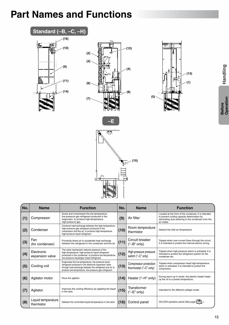
Part Names and Functions
Standard (–B, –C, –H)
(9)
(11)
(10)
(16)
(14)
(13)
(4)
(8)
(2)
(12)
(3)
(6)
(7)(5)
(1)
(15)
(1)
(2)
(3)
(4)
(5)
(6)
(7)
(8)
Compressor
Condenser
Fan (for condenser)
Electronic expansion valve
Cooling coil
Agitator motor
Agitator
Liquid temperature thermistor
Sucks and compresses the low-temperature, low-pressure gas refrigerant produced in the evaporator, to produce high-temperature, high-pressure gas.
Conducts heat exchange between the high-temperature, high-pressure gas refrigerant produced in the compressor and the air, to produce high-temperature, high-pressure liquid refrigerant.
Forcefully blows air to accelerate heat exchange between the refrigerant in the condenser and the air.
The valve mechanism reduces pressure of the high-temperature, high-pressure liquid refrigerant produced in the condenser, to produce low-temperature, low-pressure liquid/gas mixed refrigerant.
Runs the agitator.
Evaporates the low-temperature, low-pressure liquid refrigerant produced in the electronic expansion valve through heat exchange between the refrigerant and oil, to produce low-temperature, low-pressure gas refrigerant.
Improves the cooling efficiency by agitating the liquid in the tank.
Detects the controlled liquid temperature in the tank.
(9)
(10)
(11)
(12)
(13)
(14)
(15)
(16)
Air filter
Room temperature thermistor
Circuit breaker (“–B” only)
High-pressure pressure switch (“–C” only)
Compressor protection thermostat (“–C” only)
Heater (“–H” only)
Transformer (“–E” only)
Control panel
Located at the front of the condenser. It is intended to prevent cooling capacity deterioration by eliminating dust adhering to the condenser from the air intake.
Detects the inlet air temperature.
Tripped when high-pressure alarm is activated. It is intended to protect the refrigerant system for the condenser etc.
Tripped when compressor head high-temperature alarm is activated. It is intended to protect the compressor.
Tripped when over-current flows through the circuit. It is intended to protect the internal electric wiring.
During warm-up in winter, the electric heater heats up the oil to a preset temperature.
Intended for the different-voltage model.
OILCON operation panel (See page .)
No. Name Function No. Name Function
16
–E
PIM00132A_EN.fm 15 ページ 2007年9月20日 木曜日 午後3時4分
16
Bef
ore
O
per
atio
nH
and
ling
(2) (1) (3) (10) (9)
(8)(7)(6)(5)
(4)
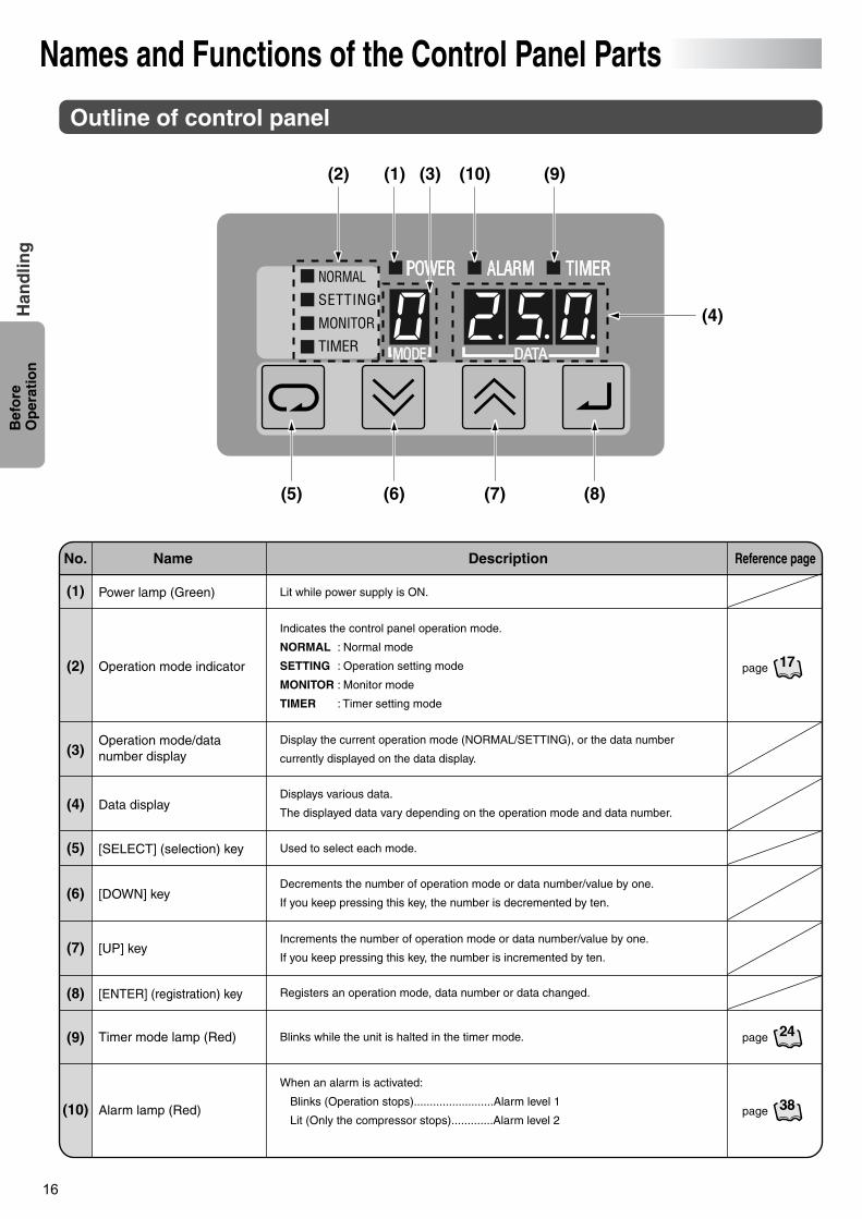
Names and Functions of the Control Panel Parts
(1)
(2)
(5)
(4)
(3)
(6)
(7)
(8)
(9)
(10)
Power lamp (Green)
No. Name Description Reference page
Operation mode indicator
Operation mode/data number display
Data display
[SELECT] (selection) key
[DOWN] key
Timer mode lamp (Red)
[ENTER] (registration) key
[UP] key
Alarm lamp (Red)
Outline of control panel
Lit while power supply is ON.
Used to select each mode.
Registers an operation mode, data number or data changed.
Indicates the control panel operation mode.
NORMAL : Normal mode
SETTING : Operation setting mode
MONITOR : Monitor mode
TIMER : Timer setting mode
When an alarm is activated:
Blinks (Operation stops).........................Alarm level 1
Lit (Only the compressor stops).............Alarm level 2
Display the current operation mode (NORMAL/SETTING), or the data number
currently displayed on the data display.
Decrements the number of operation mode or data number/value by one.
If you keep pressing this key, the number is decremented by ten.
Increments the number of operation mode or data number/value by one.
If you keep pressing this key, the number is incremented by ten.
Blinks while the unit is halted in the timer mode.
Displays various data.
The displayed data vary depending on the operation mode and data number.
page 17
page 24
page 38
PIM00132A_EN.fm 16 ページ 2007年9月20日 木曜日 午後3時4分
17
Bef
ore
O
per
atio
nH
and
ling
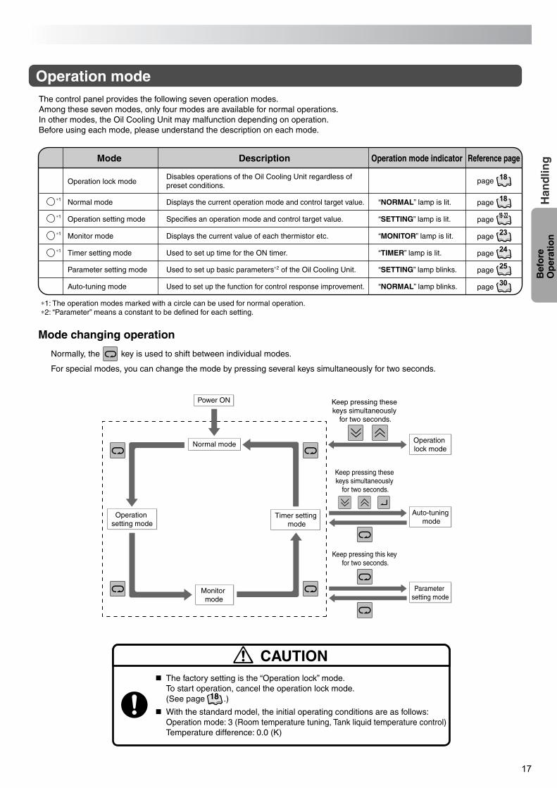
Power ON
Normal mode
Timer setting mode
Operation lock mode
Parameter setting mode
Operation setting mode
Monitor mode
Keep pressing these keys simultaneously
for two seconds.
Auto-tuning mode
Keep pressing these keys simultaneously
for two seconds.
Keep pressing this key for two seconds.
Mode Description Reference pageOperation mode indicator
Operation lock modeDisables operations of the Oil Cooling Unit regardless of preset conditions.
18page
Parameter setting mode “SETTING” lamp blinks.Used to set up basic parameters∗2 of the Oil Cooling Unit. 25page
Auto-tuning mode “NORMAL” lamp blinks.Used to set up the function for control response improvement. 30page
Normal mode∗1 “NORMAL” lamp is lit.Displays the current operation mode and control target value. 18page
∗1
∗1
∗1
Operation setting mode “SETTING” lamp is lit.Specifies an operation mode and control target value. 19 -22page
Monitor mode “MONITOR” lamp is lit.Displays the current value of each thermistor etc. 23page
Timer setting mode “TIMER” lamp is lit.Used to set up time for the ON timer. 24page
∗1: The operation modes marked with a circle can be used for normal operation.∗2: “Parameter” means a constant to be defined for each setting.
Mode changing operation
Normally, the key is used to shift between individual modes.
For special modes, you can change the mode by pressing several keys simultaneously for two seconds.
The control panel provides the following seven operation modes.Among these seven modes, only four modes are available for normal operations.In other modes, the Oil Cooling Unit may malfunction depending on operation.Before using each mode, please understand the description on each mode.
Operation mode
The factory setting is the “Operation lock” mode.To start operation, cancel the operation lock mode. (See page .)
With the standard model, the initial operating conditions are as follows:Operation mode: 3 (Room temperature tuning, Tank liquid temperature control)Temperature difference: 0.0 (K)
CAUTION
18
PIM00132A_EN.fm 17 ページ 2007年9月20日 木曜日 午後3時4分
18
Bef
ore
O
per
atio
nH
and
ling
19See page
20See page
21See page
22See page
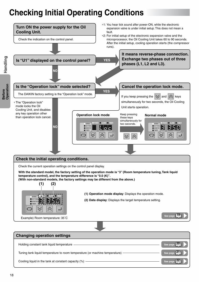
Checking Initial Operating Conditions
Turn ON the power supply for the Oil Cooling Unit.
Is “U1” displayed on the control panel?
Check the initial operating conditions.
Changing operation settings
Is the “Operation lock” mode selected? Cancel the operation lock mode.
It means reverse-phase connection. Exchange two phases out of three phases (L1, L2 and L3).
(1) Operation mode display: Displays the operation mode.
(2) Data display: Displays the target temperature setting.
Check the current operation settings on the control panel display.
With the standard model, the factory setting of the operation mode is “3” (Room temperature tuning, Tank liquid temperature control), and the temperature difference is “0.0 (K)”.(With non-standard models, the factory settings may be different from the above.)
Holding constant tank liquid temperature
Tuning tank liquid temperature to room temperature (or machine temperature)
Cooling liquid in the tank at constant capacity (%)
Check the indication on the control panel.
The DAIKIN factory setting is the “Operation lock” mode.
∗1: You hear tick sound after power-ON, while the electronic expansion valve is under initial setup. This does not mean a fault.
∗2: For initial setup of the electronic expansion valve and the microprocessor, the Oil Cooling Unit takes 60 to 90 seconds. After the initial setup, cooling operation starts (the compressor runs).
∗The “Operation lock” mode locks the Oil Cooling Unit, and disables any key operation other than operation lock cancel.
If you keep pressing the and keys
simultaneously for two seconds, the Oil Cooling
Unit starts operation.
Keep pressing these keys simultaneously for two seconds.
Operation lock mode Normal mode
YES
YES
NO
NO
(1) (2)
Example) Room temperature: 35˚C
PIM00132A_EN.fm 18 ページ 2007年9月20日 木曜日 午後3時4分
19
Bef
ore
O
per
atio
nH
and
ling
Liquid temperature thermistor (To “*1” point)
Room temperature thermistor (To “∗4” point)
Machine temperature tuning thermistor (optional) (To “∗5” point)Co
ntro
l boa
rd
∗4
B
Pressure reducingmechanismRoom temperature (Th3)
Liquid temperature
(Th4)
Machinetemperature
(Th5)
FanM
Compressor(Refrigerant only)
(Refrigerant)
∗5
(Refrigerant)
Con
dens
er
C
A
MM M
∗1
Cutting swarf disposal unit
FilterCoolant liquid
Coolant liquid
(Clean chamber) (Dirty chamber) Coolant tank (1) (with cutting swarf/coolant liquid separating equipment)
Coolant tank (2)
Eva
pora
tor
(Coo
ler)
Tool
Workpiece
M
Agitator motor
Coo
lant
liqu
id
Inta
ke a
ir
Exh
aust
air
Coolant pump
Coolant pump
Coolant pump
D
Main machine (Machine tool)
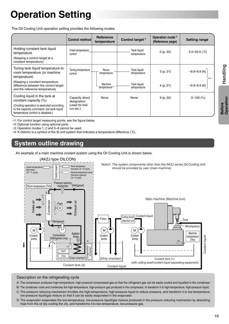
Operation SettingThe Oil Cooling Unit operation setting provides the following modes.
Holding constant tank liquid temperature(Keeping a control target at a constant temperature)
Fixed temperature control
Tank liquid temperature
0 (p. 20) 5.0–50.0 (˚C)
Tuning tank liquid temperature to room temperature (or machine temperature)(Keeping a constant temperature difference between the control target and the reference temperature)
Cooling liquid in the tank at constant capacity (%)(Cooling operation is executed according to the capacity command, but tank liquid temperature control is disabled.)
Capacity direct designation (used for trial run etc.)
None 9 (p. 22) 0–100 (%)None
Tuning temperature control
–9.9–9.9 (K)3 (p. 21)
4 (p. 21) –9.9–9.9 (K)
Tank liquid temperature
Tank liquid temperature
An example of a main machine coolant system using the Oil Cooling Unit is shown below.
System outline drawing
Description on the refrigerating cycle
∗4
∗1: For control target measuring points, see the figure below.∗2: Optional function using optional parts∗3: Operation modes 1, 2 and 5–8 cannot be used.∗4: K (Kelvin) is a symbol of the SI unit system that indicates a temperature difference (˚C).
(AKZJ type OILCON)
Control method Setting rangeOperation mode∗3
(Reference page)Reference
temperature Control target∗1
Roomtemperature
Machinetemperature∗2
A: The compressor produces high-temperature, high-pressure compressed gas so that the refrigerant gas can be easily cooled and liquefied in the condenser.
B: The condenser cools and condenses the high-temperature, high-pressure gas produced in the compressor, to transform it to high-temperature, high-pressure liquid.
C: The pressure reducing mechanism throttles the high-temperature, high-pressure liquid to reduce pressure, and transform it to low-temperature, low-pressure liquid/gas mixture so that it can be easily evaporated in the evaporator.
D: The evaporator evaporates the low-temperature, low-pressure liquid/gas mixture produced in the pressure reducing mechanism by absorbing heat from the oil (by cooling the oil), and transforms it to low-temperature, low-pressure gas.
Note)1. The system components other than the AKZJ series Oil Cooling Unit should be provided by user (main machine).
PIM00132A_EN.fm 19 ページ 2007年9月20日 木曜日 午後3時4分
20
Op
erat
ing
P
roce
du
reH
and
ling
MM
Data displayOperation mode display
Operation mode indicator
1·6 2·4 2·4 3·5
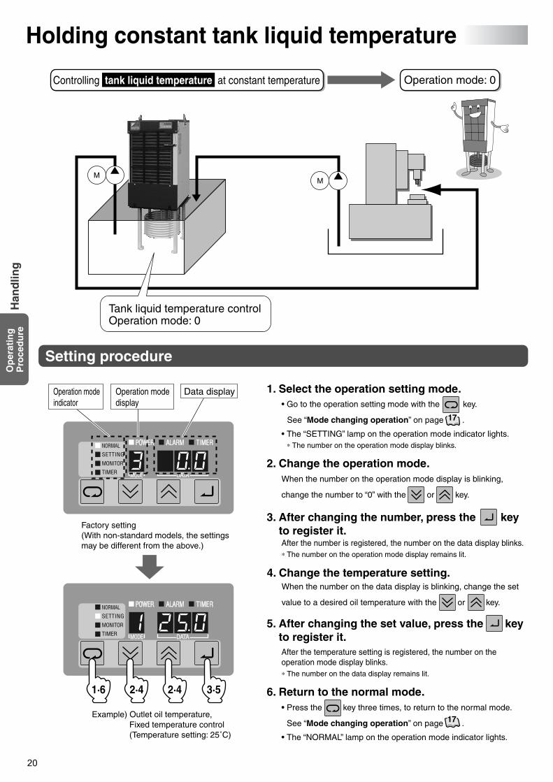
Factory setting(With non-standard models, the settings may be different from the above.)
Example) Outlet oil temperature, Fixed temperature control(Temperature setting: 25˚C)
17
17
Holding constant tank liquid temperature
Controlling tank liquid temperature at constant temperature Operation mode: 0
Tank liquid temperature controlOperation mode: 0
Setting procedure
• Go to the operation setting mode with the key.
See “Mode changing operation” on page .
• The “SETTING” lamp on the operation mode indicator lights.∗ The number on the operation mode display blinks.
1. Select the operation setting mode.
When the number on the operation mode display is blinking,
change the number to “0” with the or key.
2. Change the operation mode.
After the number is registered, the number on the data display blinks.∗ The number on the operation mode display remains lit.
3. After changing the number, press the key to register it.
After the temperature setting is registered, the number on the operation mode display blinks.∗ The number on the data display remains lit.
5. After changing the set value, press the key to register it.
When the number on the data display is blinking, change the set
value to a desired oil temperature with the or key.
4. Change the temperature setting.
• Press the key three times, to return to the normal mode.
See “Mode changing operation” on page .
• The “NORMAL” lamp on the operation mode indicator lights.
6. Return to the normal mode.
PIM00132A_EN.fm 20 ページ 2007年9月20日 木曜日 午後3時4分
21
Op
erat
ing
P
roce
du
reH
and
ling
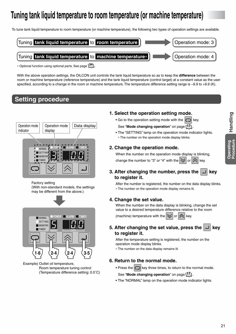
Factory setting(With non-standard models, the settings may be different from the above.)
Example) Outlet oil temperature, Room temperature tuning control(Temperature difference setting: 0.0˚C)
Data displayOperation mode display
Operation mode indicator
1·6 2·4 2·4 3·5
17
17
Tuning tank liquid temperature to room temperature (or machine temperature)To tune tank liquid temperature to room temperature (or machine temperature), the following two types of operation settings are available.
∗ Optional function using optional parts. See page .
With the above operation settings, the OILCON unit controls the tank liquid temperature so as to keep the difference between the room or machine temperature (reference temperature) and the tank liquid temperature (control target) at a constant value as the user specified, according to a change in the room or machine temperature. The temperature difference setting range is –9.9 to +9.9 (K).
Operation mode: 3
Operation mode: 4
Tuning tank liquid temperature to room temperature
Tuning tank liquid temperature to machine temperature∗34
Setting procedure
• Go to the operation setting mode with the key.
See “Mode changing operation” on page .
• The “SETTING” lamp on the operation mode indicator lights.∗ The number on the operation mode display blinks.
1. Select the operation setting mode.
When the number on the operation mode display is blinking,
change the number to “3” or “4” with the or key.
2. Change the operation mode.
After the number is registered, the number on the data display blinks.∗ The number on the operation mode display remains lit.
3. After changing the number, press the key to register it.
After the temperature setting is registered, the number on the operation mode display blinks.∗ The number on the data display remains lit.
5. After changing the set value, press the key to register it.
When the number on the data display is blinking, change the set value to a desired temperature difference relative to the room
(machine) temperature with the or key.
4. Change the set value.
• Press the key three times, to return to the normal mode.
See “Mode changing operation” on page .
• The “NORMAL” lamp on the operation mode indicator lights.
6. Return to the normal mode.
PIM00132A_EN.fm 21 ページ 2007年9月20日 木曜日 午後3時4分
22
Op
erat
ing
P
roce
du
reH
and
ling
1·6 2·4 2·4 3·5
Data displayOperation mode display
Operation mode indicator
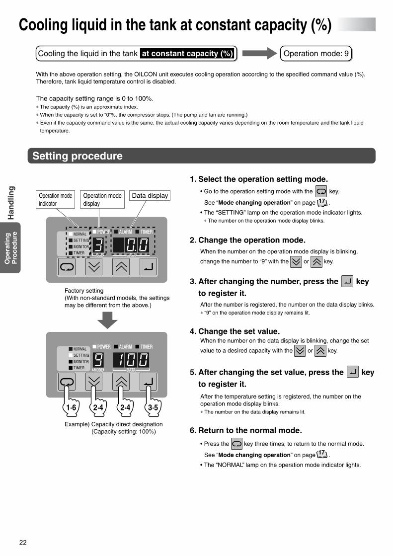
Factory setting(With non-standard models, the settings may be different from the above.)
Example) Capacity direct designation(Capacity setting: 100%)
17
17
Cooling liquid in the tank at constant capacity (%)
With the above operation setting, the OILCON unit executes cooling operation according to the specified command value (%). Therefore, tank liquid temperature control is disabled.
The capacity setting range is 0 to 100%.∗ The capacity (%) is an approximate index.
∗ When the capacity is set to “0”%, the compressor stops. (The pump and fan are running.)
∗ Even if the capacity command value is the same, the actual cooling capacity varies depending on the room temperature and the tank liquid
temperature.
Operation mode: 9Cooling the liquid in the tank at constant capacity (%)
Setting procedure
• Go to the operation setting mode with the key.
See “Mode changing operation” on page .
• The “SETTING” lamp on the operation mode indicator lights.∗ The number on the operation mode display blinks.
1. Select the operation setting mode.
When the number on the operation mode display is blinking,
change the number to “9” with the or key.
2. Change the operation mode.
After the number is registered, the number on the data display blinks.∗ “9” on the operation mode display remains lit.
3. After changing the number, press the key
to register it.
After the temperature setting is registered, the number on the operation mode display blinks.∗ The number on the data display remains lit.
5. After changing the set value, press the key
to register it.
When the number on the data display is blinking, change the set
value to a desired capacity with the or key.
4. Change the set value.
• Press the key three times, to return to the normal mode.
See “Mode changing operation” on page .
• The “NORMAL” lamp on the operation mode indicator lights.
6. Return to the normal mode.
PIM00132A_EN.fm 22 ページ 2007年9月20日 木曜日 午後3時4分
23
Use
ful
Fu
nct
ion
sH
and
ling
Data displayData number display
Operation mode indicator
1·3 2 2
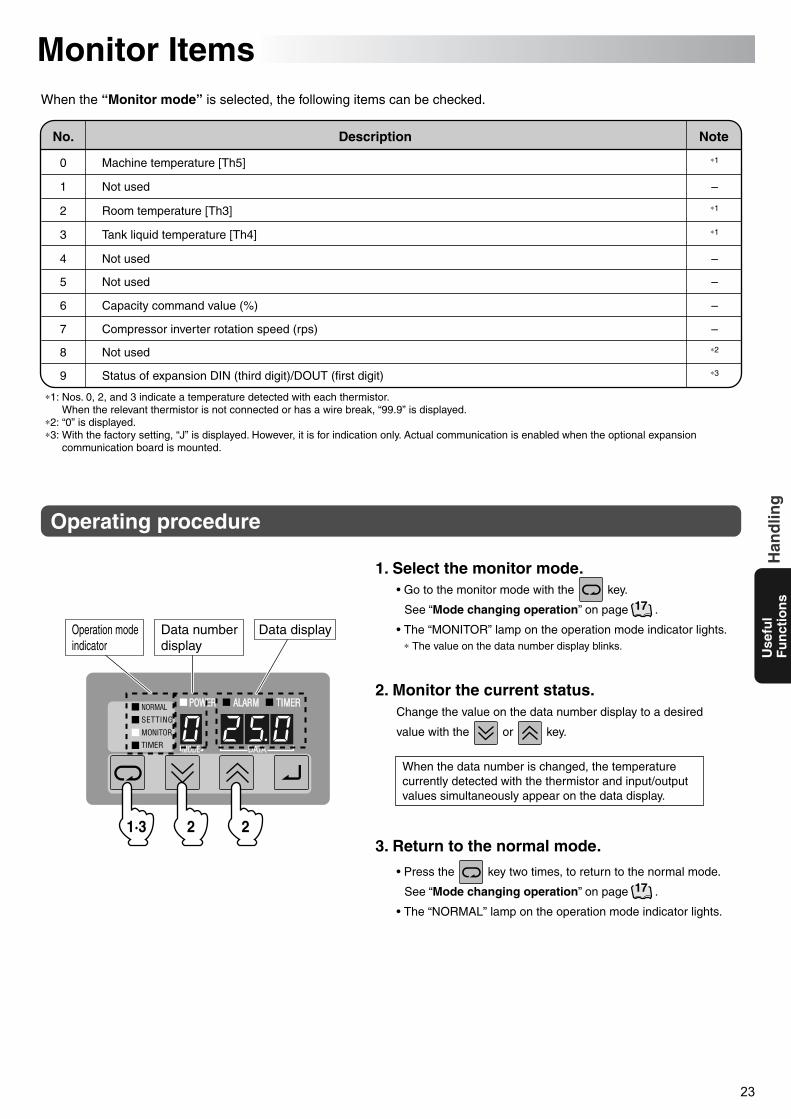
Monitor ItemsWhen the “Monitor mode” is selected, the following items can be checked.
∗1: Nos. 0, 2, and 3 indicate a temperature detected with each thermistor.When the relevant thermistor is not connected or has a wire break, “99.9” is displayed.
∗2: “0” is displayed.∗3: With the factory setting, “J” is displayed. However, it is for indication only. Actual communication is enabled when the optional expansion
communication board is mounted.
No. Description Note
∗1
–
–
–
∗2
∗3
–
∗1
∗1
–
0
5
6
7
8
9
1
2
3
4
When the data number is changed, the temperature currently detected with the thermistor and input/output values simultaneously appear on the data display.
Machine temperature [Th5]
Not used
Room temperature [Th3]
Tank liquid temperature [Th4]
Not used
Not used
Capacity command value (%)
Compressor inverter rotation speed (rps)
Not used
Status of expansion DIN (third digit)/DOUT (first digit)
• Go to the monitor mode with the key.
See “Mode changing operation” on page .
• The “MONITOR” lamp on the operation mode indicator lights.∗ The value on the data number display blinks.
• Press the key two times, to return to the normal mode.
See “Mode changing operation” on page .
• The “NORMAL” lamp on the operation mode indicator lights.
1. Select the monitor mode.
2. Monitor the current status.
3. Return to the normal mode.
Operating procedure
Change the value on the data number display to a desired
value with the or key.
17
17
PIM00132A_EN.fm 23 ページ 2007年9月20日 木曜日 午後3時4分
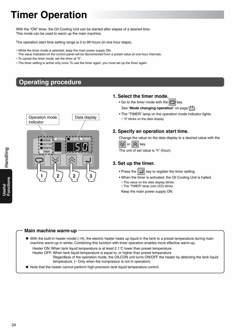
24
Use
ful
Fu
nct
ion
sH
and
ling
Data displayOperation mode indicator
1 2 2 3
Timer OperationWith the “ON” timer, the Oil Cooling Unit can be started after elapse of a desired time.This mode can be used to warm up the main machine.
The operation start time setting range is 0 to 99 hours (in one hour steps).
∗ While the timer mode is selected, keep the main power supply ON.The value indicated on the control panel will be decremented from a preset value at one-hour intervals.
∗ To cancel the timer mode, set the timer at “0”.∗ The timer setting is active only once. To use the timer again, you must set up the timer again.
Operating procedure
• Go to the timer mode with the key.
See “Mode changing operation” on page .
• The “TIMER” lamp on the operation mode indicator lights.∗ “0” blinks on the data display.
1. Select the timer mode.
Change the value on the data display to a desired value with the
or key.
The unit of set value is “h” (hour).
2. Specify an operation start time.
• Press the key to register the timer setting.
• When the timer is activated, the Oil Cooling Unit is halted.∗ The value on the data display blinks.∗ The “TIMER” lamp (red LED) blinks.
Keep the main power supply ON.
3. Set up the timer.
With the built-in heater model (–H), the electric heater heats up liquid in the tank to a preset temperature during main machine warm-up in winter. Combining this function with timer operation enables more effective warm-up.
Heater ON: When tank liquid temperature is at least 2.1˚C lower than preset temperatureHeater OFF: When tank liquid temperature is equal to, or higher than preset temperature
Regardless of the operation mode, the OILCON unit turns ON/OFF the heater by detecting the tank liquid temperature. (∗ Only when the compressor is not in operation)
Note that the heater cannot perform high-precision tank liquid temperature control.
Main machine warm-up
17
PIM00132A_EN.fm 24 ページ 2007年9月20日 木曜日 午後3時4分
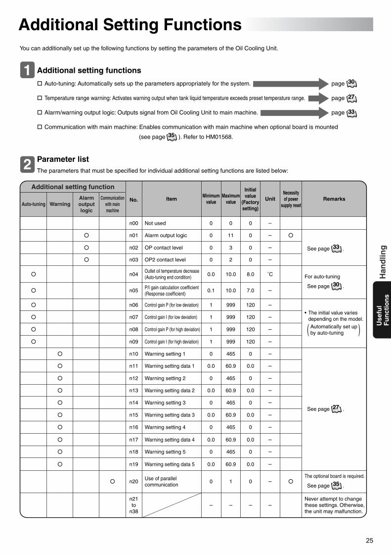
25
Use
ful
Fu
nct
ion
sH
and
ling
( )
Additional Setting FunctionsYou can additionally set up the following functions by setting the parameters of the Oil Cooling Unit.
Auto-tuning: Automatically sets up the parameters appropriately for the system. page
Temperature range warning: Activates warning output when tank liquid temperature exceeds preset temperature range. page
Alarm/warning output logic: Outputs signal from Oil Cooling Unit to main machine. page
Communication with main machine: Enables communication with main machine when optional board is mounted
(see page ). Refer to HM01568.
Additional setting functions1
The parameters that must be specified for individual additional setting functions are listed below:
Parameter list2Additional setting function
The optional board is required.
Never attempt to change these settings. Otherwise, the unit may malfunction.
• The initial value varies depending on the model.
For auto-tuning
Necessityof power
supply resetUnit
Initialvalue
(Factorysetting)
Maximumvalue
MinimumvalueItem RemarksNo.Communication
with mainmachine
Alarmoutputlogic
WarningAuto-tuning
Not used
Alarm output logic
OP contact level
OP2 contact level
Outlet oil temperature decrease (Auto-tuning end condition)
P/I gain calculation coefficient (Response coefficient)
Control gain P (for low deviation)
Control gain I (for low deviation)
Control gain P (for high deviation)
Control gain I (for high deviation)
Warning setting 1
Warning setting data 1
Warning setting 2
Warning setting data 2
Warning setting 3
Warning setting data 3
Warning setting 4
Warning setting data 4
Warning setting 5
Warning setting data 5
Use of parallel communication
n00
n01
n02
n03
n04
n05
n06
n07
n08
n09
n10
n11
n12
n13
n14
n15
n16
n17
n18
n19
n20
n21to
n38
0
0
0
0
0.0
0.1
1
1
1
1
0
0.0
0
0.0
0
0.0
0
0.0
0
0.0
0
–
0
11
3
2
10.0
10.0
999
999
999
999
465
60.9
465
60.9
465
60.9
465
60.9
465
60.9
1
–
0
0
0
0
8.0
7.0
120
120
120
120
0
0.0
0
0.0
0
0.0
0
0.0
0
0.0
0
–
–
–
–
–
˚C
–
–
–
–
–
–
–
–
–
–
–
–
–
–
–
–
–
See page .
Automatically set up by auto-tuning
30
27
33
35
33
See page .30
See page .27
See page .35
PIM00132A_EN.fm 25 ページ 2007年9月20日 木曜日 午後3時4分
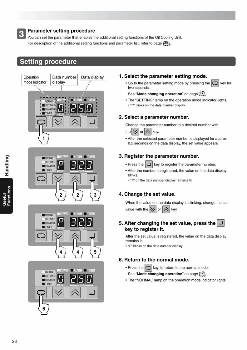
26
Use
ful
Fu
nct
ion
sH
and
ling
You can set the parameter that enables the additional setting functions of the Oil Cooling Unit.
For description of the additional setting functions and parameter list, refer to page .
Parameter setting procedure3
Setting procedure
1
2 2 3
4 4 5
Data displayData number display
Operation mode indicator • Go to the parameter setting mode by pressing the key for
two seconds.
See “Mode changing operation” on page .
• The “SETTING” lamp on the operation mode indicator lights.∗ “P” blinks on the data number display.
1. Select the parameter setting mode.
Change the parameter number to a desired number with
the or key.
• After the selected parameter number is displayed for approx. 0.5 seconds on the data display, the set value appears.
2. Select a parameter number.
• Press the key to register the parameter number.
• After the number is registered, the value on the data display blinks.∗ “P” on the data number display remains lit.
3. Register the parameter number.
After the set value is registered, the value on the data display remains lit.∗ “P” blinks on the data number display.
5. After changing the set value, press the key to register it.
When the value on the data display is blinking, change the set
value with the or key.
4. Change the set value.
• Press the key, to return to the normal mode.
See “Mode changing operation” on page .
• The “NORMAL” lamp on the operation mode indicator lights.
6. Return to the normal mode.
6
25
17
17
PIM00132A_EN.fm 26 ページ 2007年9月20日 木曜日 午後3時4分
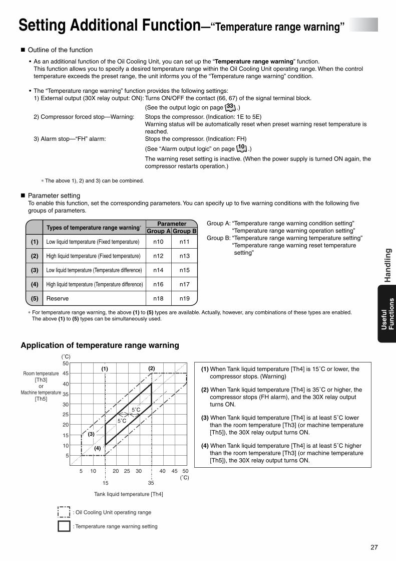
27
Use
ful
Fu
nct
ion
sH
and
ling
Tank liquid temperature [Th4]
Room temperature[Th3]
orMachine temperature
[Th5]
: Oil Cooling Unit operating range
: Temperature range warning setting
5 10
15
20 25 30
35
40 45 50
5
10
15
20
25
30
35
40
45
50
(˚C)
(˚C)
5˚C
(1)
5˚C
(2)
(3)
(4)
Setting Additional Function—“Temperature range warning”
Outline of the function
• As an additional function of the Oil Cooling Unit, you can set up the “Temperature range warning” function. This function allows you to specify a desired temperature range within the Oil Cooling Unit operating range. When the control temperature exceeds the preset range, the unit informs you of the “Temperature range warning” condition.
• The “Temperature range warning” function provides the following settings:1) External output (30X relay output: ON): Turns ON/OFF the contact (66, 67) of the signal terminal block.
(See the output logic on page .)
2) Compressor forced stop—Warning: Stops the compressor. (Indication: 1E to 5E)Warning status will be automatically reset when preset warning reset temperature is reached.
3) Alarm stop—“FH” alarm: Stops the compressor. (Indication: FH)
(See “Alarm output logic” on page .)
The warning reset setting is inactive. (When the power supply is turned ON again, the compressor restarts operation.)
∗ The above 1), 2) and 3) can be combined.
Parameter settingTo enable this function, set the corresponding parameters. You can specify up to five warning conditions with the following five groups of parameters.
∗ For temperature range warning, the above (1) to (5) types are available. Actually, however, any combinations of these types are enabled. The above (1) to (5) types can be simultaneously used.
(1) When Tank liquid temperature [Th4] is 15˚C or lower, the compressor stops. (Warning)
(2) When Tank liquid temperature [Th4] is 35˚C or higher, the compressor stops (FH alarm), and the 30X relay output turns ON.
(3) When Tank liquid temperature [Th4] is at least 5˚C lower than the room temperature [Th3] (or machine temperature [Th5]), the 30X relay output turns ON.
(4) When Tank liquid temperature [Th4] is at least 5˚C higher than the room temperature [Th3] (or machine temperature [Th5]), the 30X relay output turns ON.
Group A: “Temperature range warning condition setting”“Temperature range warning operation setting”
Group B: “Temperature range warning temperature setting”“Temperature range warning reset temperature setting”
Application of temperature range warning
Types of temperature range warning∗
(1)
(2)
(3)
(4)
(5)
ParameterGroup A Group B
Low liquid temperature (Fixed temperature)
High liquid temperature (Fixed temperature)
Low liquid temperature (Temperature difference)
High liquid temperature (Temperature difference)
Reserve
n10
n12
n14
n16
n18
n11
n13
n15
n17
n19
33
10
PIM00132A_EN.fm 27 ページ 2007年9月20日 木曜日 午後3時4分
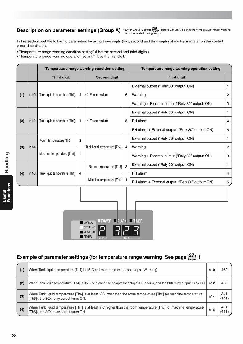
28
Use
ful
Fu
nct
ion
sH
and
ling
In this section, set the following parameters by using three digits (first, second and third digits) of each parameter on the control panel data display.
• “Temperature range warning condition setting” (Use the second and third digits.)• “Temperature range warning operation setting” (Use the first digit.)
Description on parameter settings (Group A)
Temperature range warning condition setting
(1)
Temperature range warning operation setting
Tank liquid temperature [Th4]
Tank liquid temperature [Th4]
Room temperature [Th3]
Machine temperature [Th5]
Tank liquid temperature [Th4]
External output (“Rely 30” output: ON)
Warning
Warning + External output (“Rely 30” output: ON)
External output (“Rely 30” output: ON)
FH alarm
FH alarm + External output (“Rely 30” output: ON)
External output (“Rely 30” output: ON)
Warning
Warning + External output (“Rely 30” output: ON)
External output (“Rely 30” output: ON)
FH alarm
FH alarm + External output (“Rely 30” output: ON)
Tank liquid temperature [Th4]
– Room temperature [Th3]
– Machine temperature [Th5]
Third digit
n10
(2) n12
(3) n14
(4) n16
n10 462
n12 455
n14341
(141)
n16431
(411)
1
2
3
1
4
64
4
3
1
4
5
4
3
1
5
1
2
3
1
4
5
Second digit First digit
(1) When Tank liquid temperature [Th4] is 15˚C or lower, the compressor stops. (Warning)
When Tank liquid temperature [Th4] is 35˚C or higher, the compressor stops (FH alarm), and the 30X relay output turns ON.
When Tank liquid temperature [Th4] is at least 5˚C lower than the room temperature [Th3] (or machine temperature [Th5]), the 30X relay output turns ON.
When Tank liquid temperature [Th4] is at least 5˚C higher than the room temperature [Th3] (or machine temperature [Th5]), the 30X relay output turns ON.
(2)
(3)
(4)
Example of parameter settings (for temperature range warning: See page .)
Fixed value
Fixed value
27
∗Enter Group B (page ) before Group A, so that the temperature range warning is not activated during setup.
29
PIM00132A_EN.fm 28 ページ 2007年9月20日 木曜日 午後3時4分
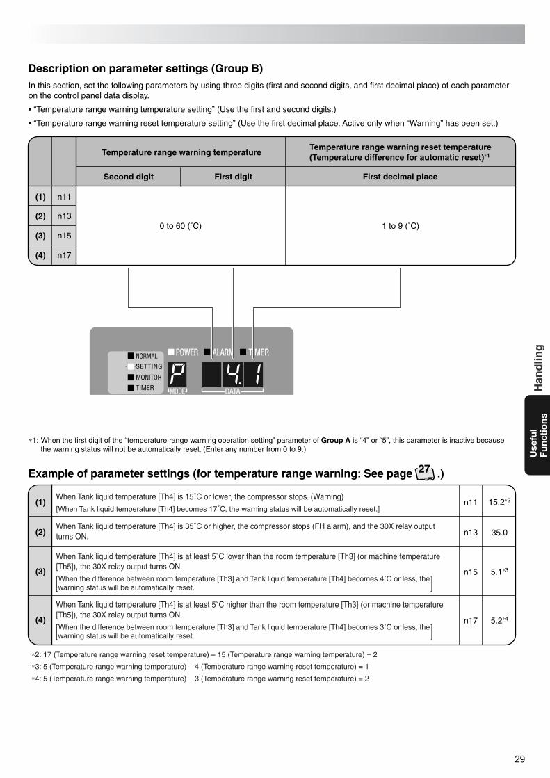
29
Use
ful
Fu
nct
ion
sH
and
ling
In this section, set the following parameters by using three digits (first and second digits, and first decimal place) of each parameter on the control panel data display.
• “Temperature range warning temperature setting” (Use the first and second digits.)
• “Temperature range warning reset temperature setting” (Use the first decimal place. Active only when “Warning” has been set.)
∗1: When the first digit of the “temperature range warning operation setting” parameter of Group A is “4” or “5”, this parameter is inactive because the warning status will not be automatically reset. (Enter any number from 0 to 9.)
Description on parameter settings (Group B)
Temperature range warning temperature
(1)
Temperature range warning reset temperature(Temperature difference for automatic reset)∗1
0 to 60 (˚C) 1 to 9 (˚C)
Second digit
n11
(2) n13
(3) n15
(4) n17
n11 15.2∗2
n13 35.0
n15 5.1∗3
n17 5.2∗4
First digit First decimal place
(1)When Tank liquid temperature [Th4] is 15˚C or lower, the compressor stops. (Warning)[When Tank liquid temperature [Th4] becomes 17˚C, the warning status will be automatically reset.]
When Tank liquid temperature [Th4] is 35˚C or higher, the compressor stops (FH alarm), and the 30X relay output turns ON.
When Tank liquid temperature [Th4] is at least 5˚C lower than the room temperature [Th3] (or machine temperature [Th5]), the 30X relay output turns ON. When the difference between room temperature [Th3] and Tank liquid temperature [Th4] becomes 4˚C or less, the warning status will be automatically reset.
When Tank liquid temperature [Th4] is at least 5˚C higher than the room temperature [Th3] (or machine temperature [Th5]), the 30X relay output turns ON. When the difference between room temperature [Th3] and Tank liquid temperature [Th4] becomes 3˚C or less, the warning status will be automatically reset.
(2)
(3)
(4)
∗2: 17 (Temperature range warning reset temperature) – 15 (Temperature range warning temperature) = 2
∗3: 5 (Temperature range warning temperature) – 4 (Temperature range warning reset temperature) = 1
∗4: 5 (Temperature range warning temperature) – 3 (Temperature range warning reset temperature) = 2
Example of parameter settings (for temperature range warning: See page .)27
PIM00132A_EN.fm 29 ページ 2007年9月20日 木曜日 午後3時4分
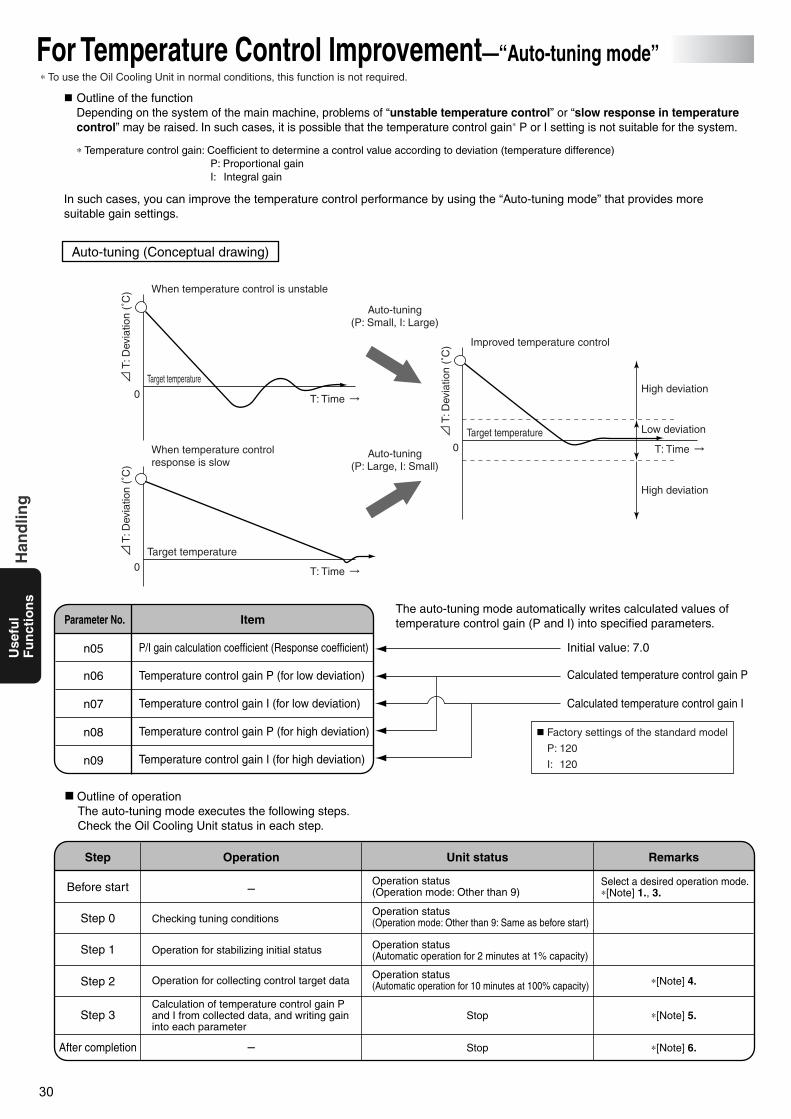
30
Use
ful
Fu
nct
ion
sH
and
ling
When temperature control is unstable
Auto-tuning(P: Small, I: Large)
Auto-tuning(P: Large, I: Small)
T: Time
T: Time
T: Time
Improved temperature control
High deviation
High deviation
Low deviation
When temperature control response is slow
Target temperature
Target temperature
Target temperature
Auto-tuning (Conceptual drawing)
P/I gain calculation coefficient (Response coefficient)
Temperature control gain P (for low deviation)
Temperature control gain I (for low deviation)
Temperature control gain P (for high deviation)
Temperature control gain I (for high deviation)
n05
n06
n07
n08
n09
–
Checking tuning conditions
Operation for stabilizing initial status
Operation for collecting control target data
Before start
Step 0
Step 1
Step 2
Calculation of temperature control gain P and I from collected data, and writing gain into each parameter
Step 3
–
Operation status (Operation mode: Other than 9)
Operation status (Operation mode: Other than 9: Same as before start)
Operation status (Automatic operation for 2 minutes at 1% capacity)
Operation status (Automatic operation for 10 minutes at 100% capacity)
Stop
Stop
Select a desired operation mode. ∗[Note] 1., 3.
∗[Note] 4.
∗[Note] 5.
∗[Note] 6.After completion
T: D
evia
tion
(˚C
)
T: D
evia
tion
(˚C
)
T: D
evia
tion
(˚C
)
For Temperature Control Improvement—“Auto-tuning mode”
Outline of the functionDepending on the system of the main machine, problems of “unstable temperature control” or “slow response in temperature control” may be raised. In such cases, it is possible that the temperature control gain∗ P or I setting is not suitable for the system.
∗ Temperature control gain: Coefficient to determine a control value according to deviation (temperature difference)P: Proportional gainI: Integral gain
In such cases, you can improve the temperature control performance by using the “Auto-tuning mode” that provides more suitable gain settings.
Outline of operationThe auto-tuning mode executes the following steps.Check the Oil Cooling Unit status in each step.
The auto-tuning mode automatically writes calculated values of temperature control gain (P and I) into specified parameters.
Calculated temperature control gain P
Initial value: 7.0
Calculated temperature control gain I
Factory settings of the standard model
P: 120
I: 120
0
0
0
ItemParameter No.
Operation Unit status RemarksStep
∗ To use the Oil Cooling Unit in normal conditions, this function is not required.
PIM00132A_EN.fm 30 ページ 2007年9月20日 木曜日 午後3時4分
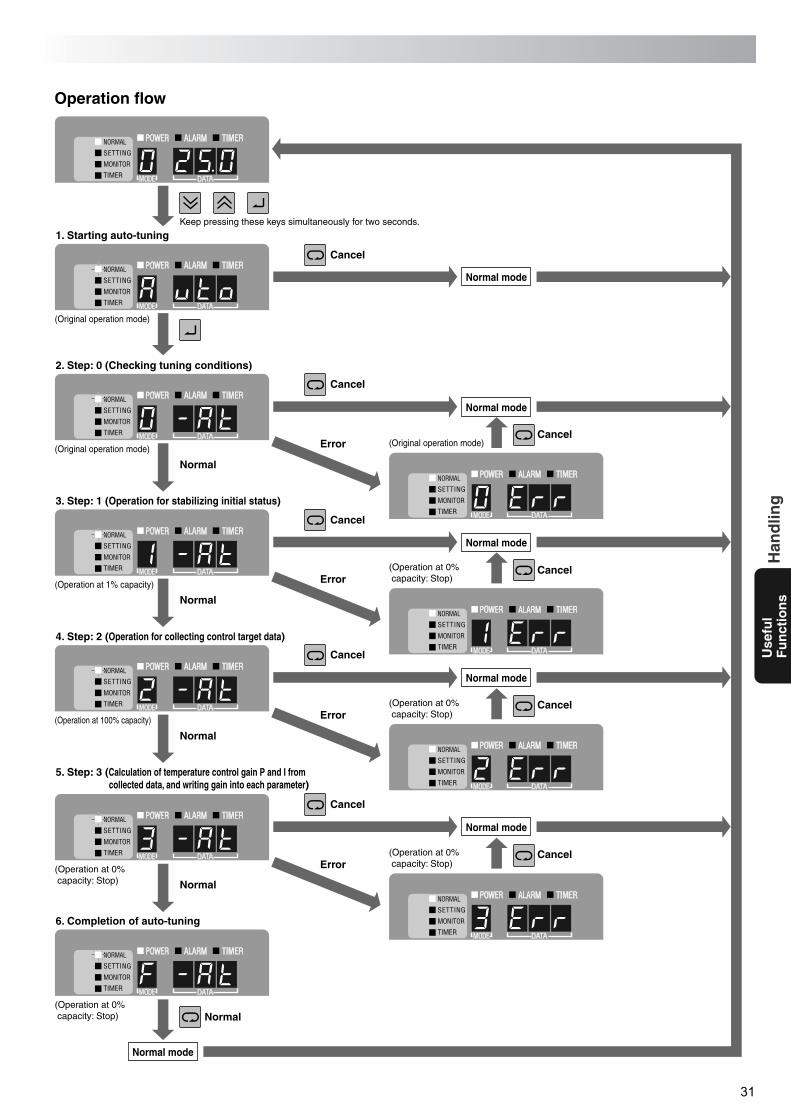
31
Use
ful
Fu
nct
ion
sH
and
ling
Operation flow
1. Starting auto-tuning
(Original operation mode)
2. Step: 0 (Checking tuning conditions)
Normal
(Original operation mode)
3. Step: 1 (Operation for stabilizing initial status)
(Operation at 1% capacity)
4. Step: 2 (Operation for collecting control target data)
(Operation at 100% capacity)
5. Step: 3 (Calculation of temperature control gain P and I from collected data, and writing gain into each parameter)
(Operation at 0% capacity: Stop)
6. Completion of auto-tuning
(Operation at 0% capacity: Stop)
Normal mode
Normal
Normal
Normal
Normal
(Original operation mode)
Keep pressing these keys simultaneously for two seconds.
Error
Cancel
Cancel
Cancel
Cancel
Cancel
Cancel
Cancel
Cancel
Cancel
(Operation at 0% capacity: Stop)Error
(Operation at 0% capacity: Stop)Error
(Operation at 0% capacity: Stop)Error
Normal mode
Normal mode
Normal mode
Normal mode
Normal mode
PIM00132A_EN.fm 31 ページ 2007年9月20日 木曜日 午後3時4分
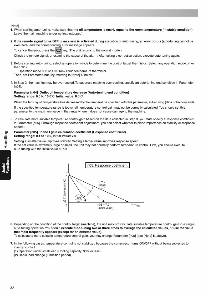
32
Use
ful
Fu
nct
ion
sH
and
ling
T: D
evia
tion
(˚C
)
T: Timen05 = 7.0(Initial value)
0
Small
Large
n05: Response coefficient
[Note]1. When starting auto-tuning, make sure that the oil temperature is nearly equal to the room temperature (in stable condition).
Leave the main machine under no load (stopped).
2. If the remote signal turns OFF or an alarm is activated during execution of auto-tuning, an error occurs (auto-tuning cannot be executed), and the corresponding error message appears.
To cancel the error, press the key. (The unit returns to the normal mode.)
Check the remote signal, or examine the cause of the alarm. After taking a corrective action, execute auto-tuning again.
3. Before starting auto-tuning, select an operation mode to determine the control target thermistor. (Select any operation mode other than “9”.)
Operation mode 0, 3 or 4 Tank liquid temperature thermistorThen, set Parameter [n04] by referring to [Note] 4. below.
4. In Step 2, the machine may be over-cooled. To suppress machine over-cooling, specify an auto-tuning end condition in Parameter [n04].
Parameter [n04] Outlet oil temperature decrease (Auto-tuning end condition)Setting range: 0.0 to 10.0˚C, Initial value: 8.0˚C
When the tank liquid temperature has decreased by the temperature specified with this parameter, auto-tuning (data collection) ends.
If the specified temperature range is too small, temperature control gain may not be correctly calculated. You should set this parameter to the maximum value in the range where it does not cause damage to the machine.
5. To calculate more suitable temperature control gain based on the data collected in Step 3, you must specify a response coefficient in Parameter [n05]. (Through response coefficient adjustment, you can select whether to place importance on stability or response speed.)
Parameter [n05] P and I gain calculation coefficient (Response coefficient)Setting range: 0.1 to 10.0, Initial value: 7.0
Setting a smaller value improves stability. Setting a larger value improves response speed.If the set value is extremely large or small, the unit may not normally perform temperature control. First, you should execute auto-tuning with the initial value of 7.0.
6. Depending on the condition of the control target (machine), the unit may not calculate suitable temperature control gain in a single auto-tuning operation. You should execute auto-tuning two or three times to average the calculated values, or use the value that most frequently appears (except for an extreme value).To calculate a more suitable temperature control gain, you may change Parameter [n05] (see [Note] 5. above).
7. In the following cases, temperature control is not stabilized because the compressor turns ON/OFF without being subjected to inverter control.(1) Operation under small load (Cooling capacity: 30% or less)(2) Rapid load change (Transition period)
PIM00132A_EN.fm 32 ページ 2007年9月20日 木曜日 午後3時4分

33
Use
ful
Fu
nct
ion
sH
and
ling
Alarm/Warning Output Logic
Alarm Settings for Optional Protection Devices (Installed by User)
The Oil Cooling Unit can output an operation status signal to the main machine through wiring to the signal terminal block and parameter setup.1. Connect the required signal cable to the signal terminal block.
(For the connecting method, refer to “Connection of external output contact” on page .)2. Set Parameter [n01].
n01: Alarm/warning output logic (First digit).
Setting 0 1 (2 to 9: Same operation as with 1)
60–61
60–63
66–67
ON
OFF
ON
OFF
ON
OFF
OFF
ON
OFF
OFF
ON
OFF
OFF
ON
OFF
ON
OFF
ON
Contact Normal Power failure Alarm Normal Power failure Alarm
Alarm output
Temperature rangewarning output
First digit: Specifies alarm output logic (60, 61, 63) and warning output logic (66, 67) of the signal terminal block.Second digit: Specifies DOUT signal output logic. (Optional communication expansion board is required.)
For details, refer to “Communication Expansion Board Instruction Manual” (HM01568).
The Oil Cooling Unit can activate an alarm by receiving an output signal from optional protection devices (e.g. flow switch).
When using OP terminals [12] and [13]:1. Connect the signal cable of the optional protection device to terminals [12] and [13] on the Oil Cooling Unit signal terminal
block.(See “Outline of electrical equipment box” on page .)
2. Set Parameter [n02].“0”: OP terminal is not used. (Factory setting)“1”: When OP contact turns OFF, Alarm Level 1 is activated.“2”: When OP contact turns OFF, Alarm Level 2 is activated.“3”: When OP contact is not ON after 30 seconds from agitator operation start, Alarm Level 1 is activated.
[CAUTION] The protection function cannot be activated simply by connecting the protection device to the OP terminals.Be sure to set this parameter.
When using OP 2 terminal [CN2]:1. Connect the signal cable of the optional protection device to [CN2] on the Oil Cooling Unit control board.
(See “Outline of electrical equipment box” on page .)2. Set Parameter [n03].
“0”: OP2 terminal is not used. (Factory setting)“1”: When OP2 contact turns OFF, Alarm Level 1 is activated.“2”: When OP2 contact turns OFF, Alarm Level 2 is activated.
[CAUTION] The protection function cannot be activated simply by connecting the protection device to the OP terminals.Be sure to set this parameter.
10
9
9
PIM00132A_EN.fm 33 ページ 2007年9月20日 木曜日 午後3時4分
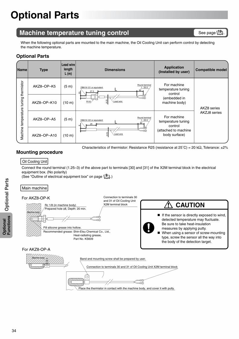
34
Op
tio
nal
F
un
ctio
ns
Op
tio
nal
Par
ts
For AKZ8-OP-K
For AKZ8-OP-A
Rc 1/8 (in machine body)Prepared hole φ8, Depth: 20 min.
Fill silicone grease into hollow.Recommended grease: Shin-Etsu Chemical Co., Ltd.,
Heat-radiating grease, Part No. KS609
Connection to terminals 30 and 31 of Oil Cooling Unit X2M terminal block
(Machine body)
Place the thermistor in contact with the machine body, and cover it with putty.
Band and mounting screw shall be prepared by user.
Connection to terminals 30 and 31 of Oil Cooling Unit X2M terminal block
(Machine body)
Optional Parts
Machine temperature tuning controlWhen the following optional parts are mounted to the main machine, the Oil Cooling Unit can perform control by detecting the machine temperature.
Connect the round terminal (1.25–3) of the above part to terminals [30] and [31] of the X2M terminal block in the electrical equipment box. (No polarity)(See “Outline of electrical equipment box” on page .)
Optional Parts
Mounting procedure
TypeName DimensionsApplication
(Installed by user) Compatible model
AKZ8–OP–K10
AKZ8–OP–A5
AKZ8–OP–A10
(10 m)
(5 m)
(10 m)
AKZ8–OP–K5 (5 m)
For machinetemperature tuning
control(attached to machine
body surface)
For machinetemperature tuning
control(embedded inmachine body)
AKZ8 seriesAKZJ8 series
Mac
hine
tem
pera
ture
tuni
ng th
erm
isto
r
Oil Cooling Unit
Main machine
If the sensor is directly exposed to wind, detected temperature may fluctuate. Be sure to take heat-insulation measures by applying putty.
When using a sensor of screw-mounting type, screw the sensor all the way into the body of the detection target.
CAUTION
DB619-121 or equivalent
27.5 801 · 25-3
(5)
(4.5
)
R1/8 Lead wire
Round terminal
(4.5
)
Lead wire
DB619-122 or equivalent
25 801 · 25-3
8
Round terminal
Lead wirelengthL (m)
See page .19
9
Characteristics of thermistor: Resistance R25 (resistance at 25˚C) = 20 kΩ, Tolerance: ±2%
PIM00132A_EN.fm 34 ページ 2007年9月20日 木曜日 午後3時4分
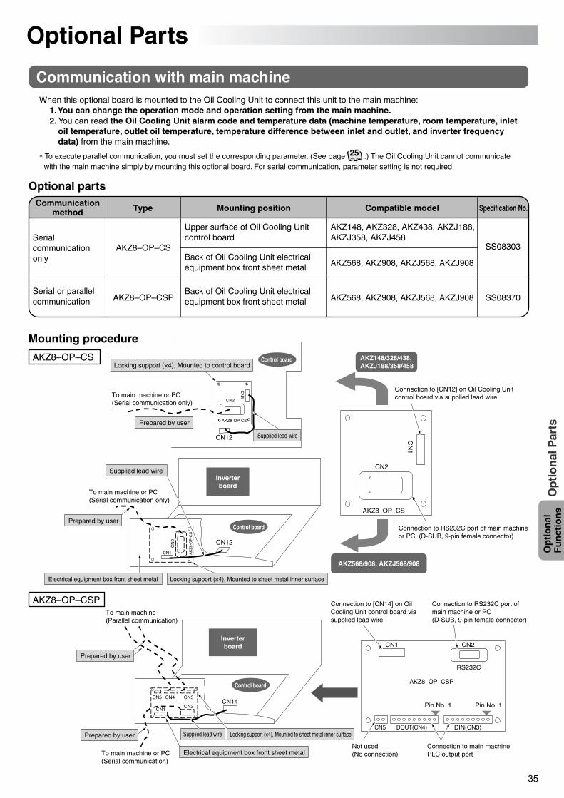
35
Op
tio
nal
F
un
ctio
ns
Op
tio
nal
Par
ts
To main machine or PC (Serial communication only)
To main machine or PC (Serial communication only)
Control board
Control board
Control board
CN
1
CN2
CN12
AKZ148/328/438,AKZJ188/358/458
Connection to [CN12] on Oil Cooling Unit control board via supplied lead wire.
CN
1
CN2
AKZ8–OP–CS
Connection to RS232C port of main machine or PC. (D-SUB, 9-pin female connector)
AKZ8-OP-CS
Inverterboard
CN1
CN
2 CN12
AK
Z8-
OP
-CS
AKZ568/908, AKZJ568/908
Connection to [CN14] on Oil Cooling Unit control board via supplied lead wire
Connection to RS232C port of main machine or PC (D-SUB, 9-pin female connector)
CN1 CN2
AKZ8–OP–CSP
Pin No. 1 Pin No. 1
DOUT(CN4) DIN(CN3)CN5
Not used (No connection)
Connection to main machine PLC output port
RS232C
CN14
To main machine or PC (Serial communication)
To main machine (Parallel communication)
CN1CN2
CN3CN4CN5
Locking support (×4), Mounted to control board
Supplied lead wire
Prepared by user
Prepared by user
Supplied lead wire
Supplied lead wire
Electrical equipment box front sheet metal
Electrical equipment box front sheet metal
Locking support (×4), Mounted to sheet metal inner surface
Locking support (×4), Mounted to sheet metal inner surface
Inverterboard
Prepared by user
Prepared by user
Optional Parts
Communication with main machineWhen this optional board is mounted to the Oil Cooling Unit to connect this unit to the main machine:
1. You can change the operation mode and operation setting from the main machine.2. You can read the Oil Cooling Unit alarm code and temperature data (machine temperature, room temperature, inlet
oil temperature, outlet oil temperature, temperature difference between inlet and outlet, and inverter frequency data) from the main machine.
∗ To execute parallel communication, you must set the corresponding parameter. (See page .) The Oil Cooling Unit cannot communicate with the main machine simply by mounting this optional board. For serial communication, parameter setting is not required.
Optional parts
TypeCommunicationmethod Mounting position Compatible model Specification No.
AKZ8–OP–CSP
AKZ8–OP–CSSerial communication only
Serial or parallel communication
AKZ148, AKZ328, AKZ438, AKZJ188,AKZJ358, AKZJ458
AKZ568, AKZ908, AKZJ568, AKZJ908
AKZ568, AKZ908, AKZJ568, AKZJ908Back of Oil Cooling Unit electrical equipment box front sheet metal
Back of Oil Cooling Unit electrical equipment box front sheet metal
Upper surface of Oil Cooling Unit control board
SS08303
SS08370
Mounting procedure
AKZ8–OP–CS
AKZ8–OP–CSP
25
PIM00132A_EN.fm 35 ページ 2007年9月20日 木曜日 午後3時4分
36
Mai
nte
nan
ceM
ain
ten
ance
If the air filter is clogged, the cooling capacity deteriorates, resulting in excess power consumption. Clean the air filter periodically to save power consumption.
Maintenance/Inspection
Daily maintenance/inspection
Periodic maintenance/inspection
• Use thorough caution about operating liquid pollution control to maintain the pollution degree at NAS10 or lower level.• Maintain the liquid level in the oil tank within the specified range. (See page .) Be sure not to allow liquid leak due to
overflow. Never attempt to operate the unit without oil.• Clean inside of the oil tank periodically to eliminate accumulated objects (cutting swarf etc.).• Make sure that the power supply voltage is within the following range:
50 Hz...........200 V ±10%60 Hz...........200/220 V ±10%
• Check if the compressor, fan or agitator does not abnormally sound during operation.• Make sure that the Oil Cooling Unit does not abnormally shake during operation.
To leave the unit unused for a long period
Return filter (See page .)• Clean the return filter at the tank return (liquid inlet) port periodically to prevent decrease in liquid level in the tank due to
dust clogging.
Air filter (See page .)• Be sure to wash the air filter with water at 40˚C or lower temperature every two weeks.
If the air filter is clogged with dust, the wind volume reduces, resulting in capacity deterioration. Also, the compressor’s protection device is activated, hindering smooth operation. Furthermore, it causes power consumption increase.
• Operating the unit without the air filter causes a fault.• To remove the air filter, hold the bottom of the filter with both hands, and push it up while warping it forward.
Condenser (See page .)• If the condenser becomes extremely dirty, clean it with a brush, air blower, etc.
(When cleaning the condenser fins, wear gloves. Otherwise, you may be injured by the sharp edges.)
Exterior• Wipe the exterior surface with a dry cloth.
Never splash water over it.• To clean the exterior, do not use a brush, polish powder, acid, solvent (benzine etc.) or hot water. Using such substances
causes the paint to peel off.
Cooling coil• If cutting swarf or chips accumulate on the OILCON cooling coil surface, it results in cooling capacity deterioration, and
also causes a fault of the unit. Check and clean the cooling coil periodically.• Remove the OILCON unit from the tank, and clean the unit with a soft non-metal brush.• During cleaning, be careful not to apply strong impact or force to the cooling coil.
• Mount a cover to the Oil Cooling Unit to prevent dust or water from entering inside of the unit.• Be sure to turn OFF the main power supply.• Be careful to keep oily dust off the condenser surface of the Oil Cooling Unit.
15
6
5
15
PIM00132A_EN.fm 36 ページ 2007年9月20日 木曜日 午後3時4分
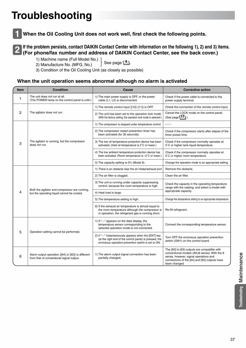
37
Troub
lesho
oting
Mai
nte
nan
ce
Troubleshooting
When the Oil Cooling Unit does not work well, first check the following points.
If the problem persists, contact DAIKIN Contact Center with information on the following 1), 2) and 3) items. (For phone/fax number and address of DAIKIN Contact Center, see the back cover.)
1) Machine name (Full Model No.) 2) Manufacture No. (MFG. No.)3) Condition of the Oil Cooling Unit (as closely as possible)
When the unit operation seems abnormal although no alarm is activated
Item Condition Cause Corrective action
The unit does not run at all.(The POWER lamp on the control panel is unlit.)
The agitator is running, but the compressor does not run.
Both the agitator and compressor are running, but the operating liquid cannot be cooled.
Alarm output operation ([64] or [65]) is different from that of conventional signal output.
Operation setting cannot be performed.
The agitator does not run.
– – –
1
2
3
4
5
6
1
2See page .4
1) The main power supply is OFF, or the power cable (L1, L2) is disconnected.
2) The compressor restart prevention timer has been activated (for 30 seconds).
3) The low oil temperature protection device has been activated. (Inlet oil temperature is 2˚C or lower.)
6) If the exhaust air temperature is almost equal to the room temperature although the compressor is in operation, the refrigerant gas is running short.
1) If “---” appears on the data display, the temperature sensor corresponding to the selected operation mode is not connected.
2) If “---” instantaneously appears when the [ENT] key (at the right end of the control panel) is pressed, the erroneous operation prevention switch is set to ON.
4) The low ambient temperature protection device has been activated. (Room temperature is –2˚C or lower.)
1) The remote control input ([10]–[11]) is OFF.
1) The compressor is stopped under temperature control.
5) The capacity setting is 0% (Mode 9).
1) There is an obstacle near the air intake/exhaust port.
2) The air filter is clogged.
3) The unit is running under capacity suppressing control, because the room temperature is high.
1) The alarm output signal connection has been partially changed.
4) Heat load is large.
5) The temperature setting is high.
2) The unit has been set to the operation lock mode.(With the factory setting, the operation lock mode is selected.)
Check if the power cable is connected to the power supply terminal.
Check if the compressor starts after elapse of the timer preset time.
Check if the compressor normally operates at 5˚C or higher tank liquid temperature.
Check if the compressor normally operates at 0˚C or higher room temperature.
Turn OFF the erroneous operation prevention switch (SW1) on the control board.
Check the capacity in the operating temperature range with the catalog, and select a model with appropriate capacity.
The [60] to [63] outputs are compatible with conventional models (AKJ6 series). With the 8 series, however, signal operations and connections of the [64] and [65] outputs have been changed.
Connect the corresponding temperature sensor.
Cancel the LOCK mode on the control panel.
(See page .)
Check the connection of the remote control input.
Change the operation mode to an appropriate setting.
Remove the obstacle.
Clean the air filter.
Re-fill refrigerant.
Change the temperature setting to an appropriate temperature.
17
PIM00132A_EN.fm 37 ページ 2007年9月20日 木曜日 午後3時4分
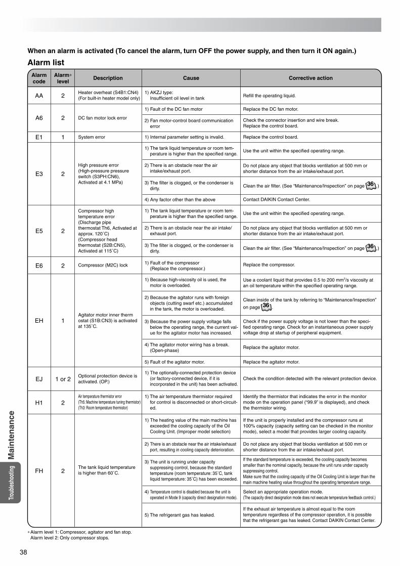
38
Mai
nte
nan
ceTro
ubles
hoot
ing
When an alarm is activated (To cancel the alarm, turn OFF the power supply, and then turn it ON again.)
Alarm listAlarmcode
Alarm∗level
Description Cause Corrective action
Heater overheat (S4B1:CN4)(For built-in heater model only)
DC fan motor lock error
High pressure error (High-pressure pressure switch (S3PH:CN6), Activated at 4.1 MPa)
Compressor high temperature error (Discharge pipe thermostat Th6, Activated at approx. 120˚C)(Compressor head thermostat (S2B:CN5), Activated at 115˚C)
Compressor (M2C) lock
System error
∗Alarm level 1: Compressor, agitator and fan stop.Alarm level 2: Only compressor stops.
Agitator motor inner thermostat (S1B:CN3) is activated at 135˚C.
Optional protection device is activated. (OP.)
Air temperature thermistor error(Th5: Machine temperature tuning thermistor)(Th3: Room temperature thermistor)
The tank liquid temperature is higher than 60˚C.
AA 2
A6 2
E1 1
E3 2
E5 2
E6 2
EH 1
EJ 1 or 2
H1 2
FH 2
1) AKZJ type:Insufficient oil level in tank
1) Fault of the DC fan motor
1) Internal parameter setting is invalid.
4) Any factor other than the above
5) The refrigerant gas has leaked.
2) Fan motor-control board communication error
1) The tank liquid temperature or room tem-perature is higher than the specified range.
2) There is an obstacle near the air intake/exhaust port.
3) The filter is clogged, or the condenser is dirty.
1) The tank liquid temperature or room tem-perature is higher than the specified range.
2) There is an obstacle near the air intake/exhaust port.
3) The filter is clogged, or the condenser is dirty.
1) Fault of the compressor(Replace the compressor.)
1) Because high-viscosity oil is used, the motor is overloaded.
4) The agitator motor wiring has a break. (Open-phase)
3) Because the power supply voltage falls below the operating range, the current val-ue for the agitator motor has increased.
1) The air temperature thermistor required for control is disconnected or short-circuit-ed.
2) There is an obstacle near the air intake/exhaust port, resulting in cooling capacity deterioration.
4) Temperature control is disabled because the unit is operated in Mode 9 (capacity direct designation mode).
2) Because the agitator runs with foreign objects (cutting swarf etc.) accumulated in the tank, the motor is overloaded.
1) The optionally-connected protection device (or factory-connected device, if it is incorporated in the unit) has been activated.
1) The heating value of the main machine has exceeded the cooling capacity of the Oil Cooling Unit. (Improper model selection)
3) The unit is running under capacity suppressing control, because the standard temperature (room temperature: 35˚C, tank liquid temperature: 35˚C) has been exceeded.
Refill the operating liquid.
Check the connector insertion and wire break.Replace the control board.
Do not place any object that blocks ventilation at 500 mm or shorter distance from the air intake/exhaust port.
Do not place any object that blocks ventilation at 500 mm or shorter distance from the air intake/exhaust port.
Clean inside of the tank by referring to “Maintenance/Inspection”
on page .
Identify the thermistor that indicates the error in the monitor mode on the operation panel (“99.9” is displayed), and check the thermistor wiring.
If the unit is properly installed and the compressor runs at 100% capacity (capacity setting can be checked in the monitor mode), select a model that provides larger cooling capacity.
If the exhaust air temperature is almost equal to the room temperature regardless of the compressor operation, it is possible that the refrigerant gas has leaked. Contact DAIKIN Contact Center.
If the standard temperature is exceeded, the cooling capacity becomes smaller than the nominal capacity, because the unit runs under capacity suppressing control.Make sure that the cooling capacity of the Oil Cooling Unit is larger than the main machine heating value throughout the operating temperature range.
Do not place any object that blocks ventilation at 500 mm or shorter distance from the air intake/exhaust port.
Select an appropriate operation mode.(The capacity direct designation mode does not execute temperature feedback control.)
Use a coolant liquid that provides 0.5 to 200 mm2/s viscosity at an oil temperature within the specified operating range.
Check the condition detected with the relevant protection device.
Clean the air filter. (See “Maintenance/Inspection” on page .)
Replace the DC fan motor.
Replace the control board.
Use the unit within the specified operating range.
Contact DAIKIN Contact Center.
Use the unit within the specified operating range.
Replace the compressor.
Check if the power supply voltage is not lower than the speci-fied operating range. Check for an instantaneous power supply voltage drop at startup of peripheral equipment.
Replace the agitator motor.
5) Fault of the agitator motor. Replace the agitator motor.
36
Clean the air filter. (See “Maintenance/Inspection” on page .)36
36
PIM00132A_EN.fm 38 ページ 2007年9月20日 木曜日 午後3時4分
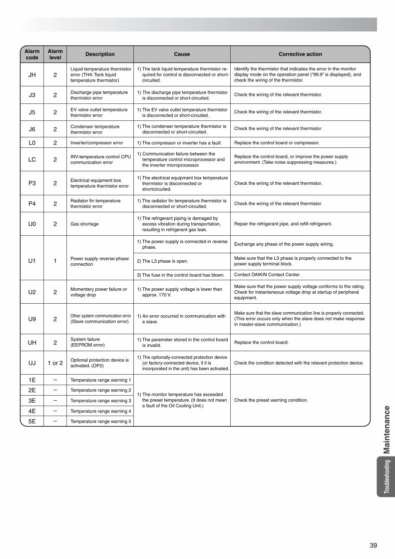
39
Troub
lesho
oting
Mai
nte
nan
ce
Alarmcode
Alarmlevel
Description Cause Corrective action
Liquid temperature thermistor error (TH4: Tank liquid temperature thermistor)
Discharge pipe temperature thermistor error
EV valve outlet temperature thermistor error
Condenser temperature thermistor error
Inverter/compressor error
INV-temperature control CPU communication error
Electrical equipment box temperature thermistor error
Radiator fin temperature thermistor error
Gas shortage
Power supply reverse-phase connection
Momentary power failure or voltage drop
Other system communication error(Slave communication error)
System failure (EEPROM error)
Optional protection device is activated. (OP2)
Temperature range warning 1
Temperature range warning 5
JH 2
J3 2
J5 2
J6 2
L0 2
LC 2
P3 2
P4 2
U0 2
U1 1
U2 2
U9 2
UH 2
UJ 1 or 2
1E –
Temperature range warning 22E –
Temperature range warning 33E –
Temperature range warning 44E –
5E –
Check the wiring of the relevant thermistor.
Check the wiring of the relevant thermistor.
Check the wiring of the relevant thermistor.
Check the wiring of the relevant thermistor.
Repair the refrigerant pipe, and refill refrigerant.
Exchange any phase of the power supply wiring.
Contact DAIKIN Contact Center.
Replace the control board.
Check the preset warning condition.
Check the wiring of the relevant thermistor.
Replace the control board or compressor.
Identify the thermistor that indicates the error in the monitor display mode on the operation panel (“99.9” is displayed), and check the wiring of the thermistor.
Replace the control board, or improve the power supply environment. (Take noise suppressing measures.)
Make sure that the L3 phase is properly connected to the power supply terminal block.
Check the condition detected with the relevant protection device.
Make sure that the power supply voltage conforms to the rating.Check for instantaneous voltage drop at startup of peripheral equipment.
Make sure that the slave communication line is properly connected.(This error occurs only when the slave does not make response in master-slave communication.)
1) The tank liquid temperature thermistor re-quired for control is disconnected or short-circuited.
1) The discharge pipe temperature thermistor is disconnected or short-circuited.
1) The EV valve outlet temperature thermistor is disconnected or short-circuited.
1) The condenser temperature thermistor is disconnected or short-circuited.
1) Communication failure between the temperature control microprocessor and the inverter microprocessor.
1) The electrical equipment box temperature thermistor is disconnected or shortcircuited.
1) The radiator fin temperature thermistor is disconnected or short-circuited.
1) The power supply voltage is lower than approx. 170 V.
1) An error occurred in communication with a slave.
1) The parameter stored in the control board is invalid.
1) The optionally-connected protection device (or factory-connected device, if it is incorporated in the unit) has been activated.
1) The monitor temperature has exceeded the preset temperature. (It does not mean a fault of the Oil Cooling Unit.)
1) The refrigerant piping is damaged by excess vibration during transportation, resulting in refrigerant gas leak.
1) The compressor or inverter has a fault.
1) The power supply is connected in reverse phase.
2) The L3 phase is open.
3) The fuse in the control board has blown.
PIM00132A_EN.fm 39 ページ 2007年9月20日 木曜日 午後3時4分

PIM00132A_JA.fm 0 ページ 2007年9月20日 木曜日 午後2時4分

PIM00132A_JA.fm 0 ページ 2007年9月20日 木曜日 午後2時4分
Oil Hydraulic Equipment
Osaka OfficeDAIKIN Esaka Building, Tarumi-cho 3-21-3,Suita, Osaka, Japan 564-0062TEL : 81-6-6378-8764FAX : 81-6-6378-8738E-mail Address: [email protected] Page: http://www.daikin.co.jp
PIM00132A HT(0710)
PIM00132A_EN.fm 40 ページ 2007年9月20日 木曜日 午後3時4分


![High-temperature LM Guide Series - THK · 2010-06-04 · • 3 • Precautions on the Use of the THK High-temperature LM Guide [Operating Temperature of High-temperature LM Guide]](https://img.pdfslide.us/doc/110x75/5e737b81d316ce3fb11f5599/high-temperature-lm-guide-series-thk-2010-06-04-a-3-a-precautions-on-the.jpg)