Embed Size (px)
DESCRIPTION
Precast
Citation preview
CONCAST PRECAST GROUP
CIVIL ENGINEERING SOLUTIONS
Copyright Concast Precast Ltd © 2009
Note: Please note technical information provided is for guidance only, project specific requirements should be discussed at the appropriate time.
Range of projects 2
Our Service 3
Bridge Beams 4
TY Beams
TYE Beams
M Beams
Y Beams
YE Beams
U Beams
CSU Beams (Concast Super U)
Bridge Decks 8
Glass Reinforced Concrete (GRC)
Omnia Slab
Ramp Slabs
Retaining Walls 9
Culverts 10
Wingwalls
Headwalls
1
The Concast Precast Group is a major provider of precast concrete
solutions servicing the Irish and UK markets. Founded in 1975, Concast’s
business has grown through our reputation for delivering quality projects,
on time and within budget.
Concast has a professional cross functional team with the expertise and
state of the art facilities to deliver an extensive range of precast solutions.
Concast offers both public and private sector clients a comprehensive
service including design, production, transportation and installation on site.
Concast provides precast solutions to a wide range of developments
including road and rail projects, multi-storey car parks, office blocks,
residential schemes, industrial schemes, sports stadia and power plants.
Contents
2
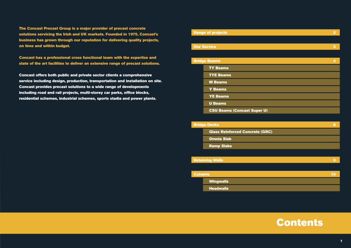
1. Docklands Residential SchemeConcast provides multi-storey structural precast concretesolutions for major residential schemes, including luxuryapartments, duplexes and townhouses, social-affordableschemes and student accommodation. Concast’s design teamprovides flexible solutions, to suit modern designs. In addition tothe structural frame, Concast can provide additional productssuch as precast balconies, cladding panels, lift-core pods.
2. Sports and Leisure StadiaConcast are a leading manufacturer of sports and leisurefacilities including spectator stands which generally incorporateauxiliary facilities such as changing rooms, meeting rooms,conference and exhibition space.
3. Multi-storey Car ParksPrecast provides flexible and competitive solutions for all typesof multi-storey car parks, from stand-alone car parks, tounderground or basement car parks on multi-storey commercial,industrial and residential schemes.
1 2 3
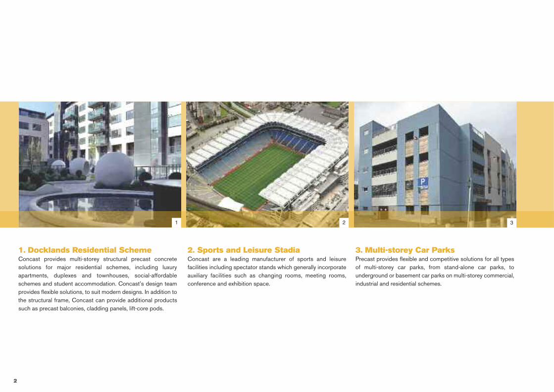
Concast Provide a Quality Service
Design & PlanningConcast’s in-house designers, workclosely with our clients design team todeliver a flexible and innovative solution forevery project undertaken.
It is essential to identify the most efficientsizes and shapes for components, at anearly stage. This ensures structuralefficiency and minimises cost.
3
Production & ISO QualityControlsConcast has invested heavily in plant andequipment; our modern moulding systemsproduce a consistently high quality product.
Concast has been awarded ISO 9001 QualityCertification, which is independently monitored.
Transport & InstallationConcast has a fleet of specialist equipment,to facilitate the transportation andinstallation of our precast concreteproducts. Professional crews, complete theinstallation process on site.
Concast is committed to delivering projectson programme and within budget in a safeand efficient manner.
Health & SafetySafe working procedures are implemented atall stages of the process from the initial designrisk assessment right through to the completionof the safety file.
Precast construction keeps the site, cleanerand improves logistics on site.
4
Bridge Beams
Bridge Beams
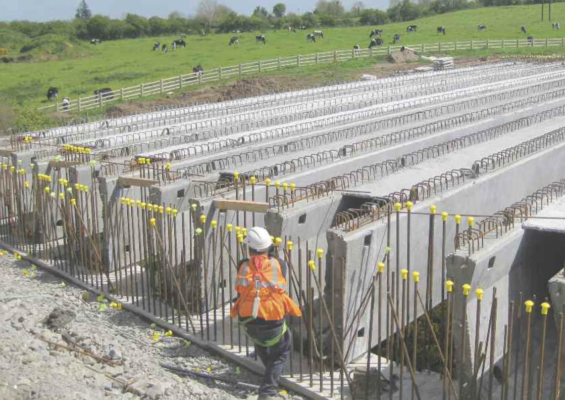
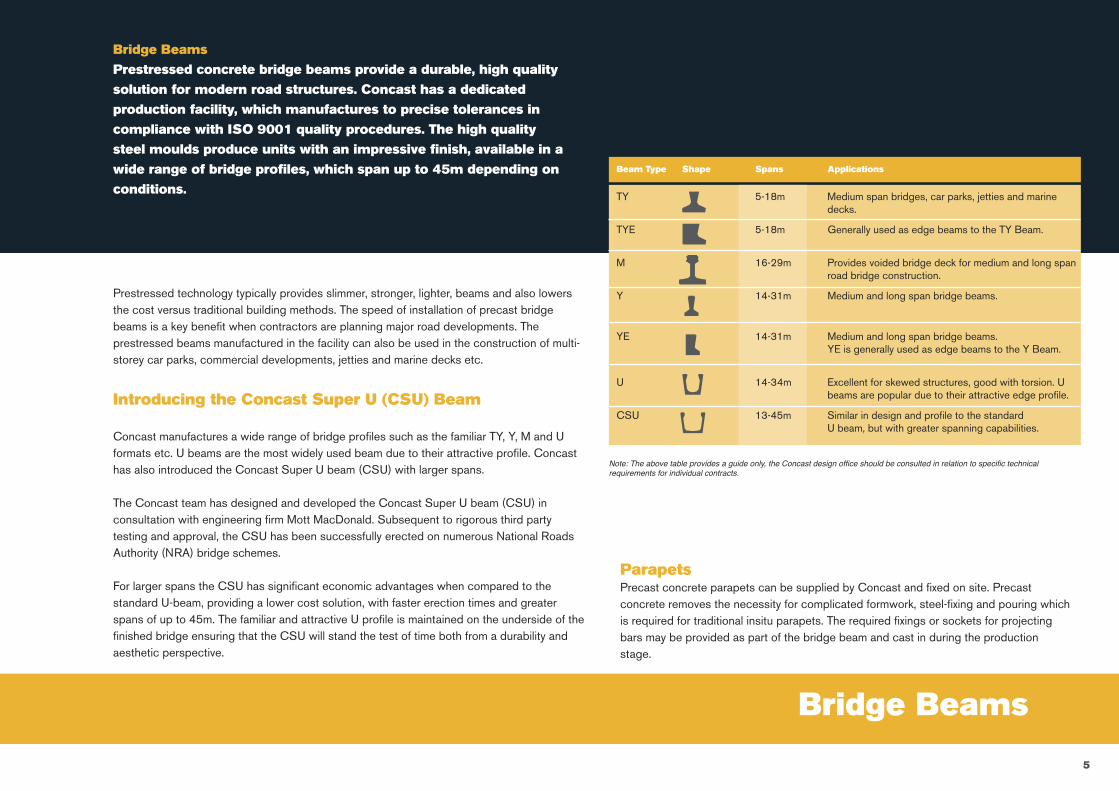
Prestressed concrete bridge beams provide a durable, high quality
solution for modern road structures. Concast has a dedicated
production facility, which manufactures to precise tolerances in
compliance with ISO 9001 quality procedures. The high quality
steel moulds produce units with an impressive finish, available in a
wide range of bridge profiles, which span up to 45m depending on
conditions.
Introducing the Concast Super U (CSU) Beam
Concast manufactures a wide range of bridge profiles such as the familiar TY, Y, M and Uformats etc. U beams are the most widely used beam due to their attractive profile. Concasthas also introduced the Concast Super U beam (CSU) with larger spans.
The Concast team has designed and developed the Concast Super U beam (CSU) inconsultation with engineering firm Mott MacDonald. Subsequent to rigorous third partytesting and approval, the CSU has been successfully erected on numerous National RoadsAuthority (NRA) bridge schemes.
For larger spans the CSU has significant economic advantages when compared to thestandard U-beam, providing a lower cost solution, with faster erection times and greaterspans of up to 45m. The familiar and attractive U profile is maintained on the underside of thefinished bridge ensuring that the CSU will stand the test of time both from a durability andaesthetic perspective.
Prestressed technology typically provides slimmer, stronger, lighter, beams and also lowersthe cost versus traditional building methods. The speed of installation of precast bridgebeams is a key benefit when contractors are planning major road developments. Theprestressed beams manufactured in the facility can also be used in the construction of multi-storey car parks, commercial developments, jetties and marine decks etc.
ParapetsPrecast concrete parapets can be supplied by Concast and fixed on site. Precastconcrete removes the necessity for complicated formwork, steel-fixing and pouring whichis required for traditional insitu parapets. The required fixings or sockets for projectingbars may be provided as part of the bridge beam and cast in during the productionstage.
TY 5-18m Medium span bridges, car parks, jetties and marinedecks.
TYE 5-18m Generally used as edge beams to the TY Beam.
M 16-29m Provides voided bridge deck for medium and long spanroad bridge construction.
Y 14-31m Medium and long span bridge beams.
YE 14-31m Medium and long span bridge beams. YE is generally used as edge beams to the Y Beam.
U 14-34m Excellent for skewed structures, good with torsion. Ubeams are popular due to their attractive edge profile.
CSU 13-45m Similar in design and profile to the standardU beam, but with greater spanning capabilities.
Beam Type Shape Spans Applications
Note: The above table provides a guide only, the Concast design office should be consulted in relation to specific technicalrequirements for individual contracts.
5
TY1
Section No
Depth [mm]
Area [mm2]
Height centroid above soffit Yb
[mm] Zt (top)[mm3 x 10^6]
Approximate self weight
[kN/m]
400TY2TY3TY4TY5TY6TY7
450500550600650700
188663200046212444225858240288255733272194
SECTION PROPERTIES Design self weight per unit has been taken as 24kN/m3
145.5161.4179.7200.2222.7247.0272.9
4.534.805.105.435.776.146.54
7.69 13.469.71 17.35
12.35 22.0015.62 27.2819.54 33.1024.14 39.3829.42 46.04
TY8 750 289671 300.2 6.9635.41 53.06TY9 800 308163 328.6 7.4042.11 60.40
TY10 850 327671 358.2 7.8749.56 68.05TY11 900 348244 388.6 8.3657.76 76.01
Section modulus
Zb (bottom)[mm3 x 10^6]
Second moment of area
[mm4 x 10^9]
1.95812.80113.95385.46307.37309.726612.56515.92619.85124.37529.539
B [mm]
218238258279299319339360380400421
Span [m]
4.5 - 8.57.5 - 9.5
8.5 - 10.59.5 - 11.5
10.5 - 12.511.5 - 13.512.5 - 14.513.5 - 15.514.5 - 16.515.5 - 17.5
16 - 18
PROFILE
D
(dep
th)
B
750
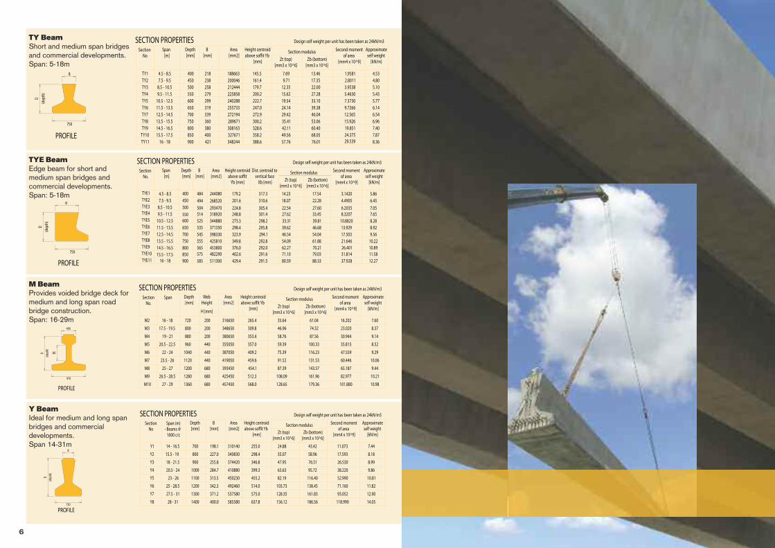
TY BeamShort and medium span bridgesand commercial developments.Span: 5-18m
Section No.
Depth [mm]
Area [mm2]
Zt (top)[mm3 x 10^6]
Approximate self weight
[kN/m]
SECTION PROPERTIES Design self weight per unit has been taken as 24kN/m3
Section modulus
Zb (bottom)[mm3 x 10^6]
Second moment of area
[mm4 x 10^9]
B [mm]
317.3310.6
305.4301.4298.2295.8294.1
5.866.45
7.057.658.288.929.56
14.23 17.5418.07 22.28
22.54 27.6027.62 33.4533.31 39.8139.62 46.6846.54 54.04
292.8 10.2254.09 61.88292.0 10.8962.27 70.21291.6 11.5871.10 79.03291.5 12.2780.59 88.33
3.14204.4905
6.20358.3207
10.882013.92917.50321.64626.40131.81437.928
484
494
504514525535545
244080
268520
293470318920344880371350398330
555 425810565 453800575 482290585 511300
TYE1TYE2TYE3TYE4TYE5TYE6TYE7TYE8TYE9TYE10TYE11
400450500
550600650700750800850900
Height centroid above soffit
Yb [mm]
Dist. centroid to vertical face
Xb [mm]
179.2201.6
224.8248.8273.3298.4323.9349.8376.0402.6429.4
Span [m]
4.5 - 8.57.5 - 9.5
8.5 - 10.59.5 - 11.5
10.5 - 12.511.5 - 13.512.5 - 14.513.5 - 15.514.5 - 16.515.5 - 17.5
16 - 18
PROFILE
D
(dep
th)
B
750
TYE BeamEdge beam for short andmedium span bridges andcommercial developments.Span: 5-18m
M2
Section No.
Depth [mm]
Area [mm2]
Height centroid above soffit Yb
[mm] Zt (top)[mm3 x 10^6]
Approximate self weight
[kN/m]
720
M3
M4
M5
M6
M7
M8
800
880
960
1040
1120
316650
348650
380650
355050
387050
419050
393450
SECTION PROPERTIES Design self weight per unit has been taken as 24kN/m3
265.4
309.8
353.4
357.0
409.2
459.6
454.1
7.60
8.37
9.14
8.52
9.29
10.06
9.44
35.64 61.04
46.96 74.32
58.76 87.56
59.39 100.33
75.39 116.23
91.52 131.53
87.39 143.57
M9 425450 512.3 10.21108.09 161.96
Section modulus
Zb (bottom)[mm3 x 10^6]
Second moment of area
[mm4 x 10^9]
16.202
23.020
30.944
35.813
47.559
60.446
65.187
82.977
Web Height
200
440
1200
1280
457450 568.0 10.98128.65 179.36 101.8801360M10
H [mm]
200
200
440
440
680
680
680
WeightThe customer should assume a concrete density of 2.5t / m3.
Quality ControlWe carry out strict quality control procedures at all stages of manufacture. Copies of all necessary certificates on cement, aggregates, strands, stressing records, cube tests and beam tests are retained within our quality system.
125
Span (m)
14.5 - 20
16 - 22
17.5 - 24.5
19 - 26.5
21 - 28.5
22.5 - 30.5
13 - 18.5
24 - 32
25.5 - 34
27.5 - 36
29 - 37.5
30.5 - 39
32 - 40.5
33.5 - 41
35 - 43.5
36.5 - 45
Section No.
Depth [mm]
Area [mm2]
Zt (top)[mm3 x 10^6]
Approximate self weight
[kN/m]
SECTION PROPERTIES Design self weight per unit has been taken as 24kN/m3
Section modulus
Zb (bottom)[mm3 x 10^6]
Second moment of area
[mm4 x 10^9]
B [mm]
317.3310.6
305.4301.4298.2295.8294.1
5.866.45
7.057.658.288.929.56
14.23 17.5418.07 22.28
22.54 27.6027.62 33.4533.31 39.8139.62 46.6846.54 54.04
292.8 10.2254.09 61.88292.0 10.8962.27 70.21291.6 11.5871.10 79.03291.5 12.2780.59 88.33
3.14204.4905
6.20358.3207
10.882013.92917.50321.64626.40131.81437.928
484
494
504514525535545
244080
268520
293470318920344880371350398330
555 425810565 453800575 482290585 511300
TYE1TYE2TYE3TYE4TYE5TYE6TYE7TYE8TYE9TYE10TYE11
400450500
550600650700750800850900
Height centroid above soffit
Yb [mm]
Dist. centroid to vertical face
Xb [mm]
179.2201.6
224.8248.8273.3298.4323.9349.8376.0402.6429.4
Span (m)- Beams @
1000 c/c
14 - 16.5
15.5 - 19
18 - 21.5
20.5 - 24
23 - 26
25 - 28.5
27.5 - 31
28 - 31
Section No
Span (m)- Beams @
1000 c/c
14 - 16.5
15.5 - 19
18 - 21.5
20.5 - 24
23 - 26
25 - 28.5
27.5 - 31
28 - 31
Span
16 - 18
17.5 - 19.5
19 - 21
20.5 - 22.5
22 - 24
23.5 - 26
25 - 27
26.5 - 28.5
27 - 29
Span [m]
4.5 - 8.57.5 - 9.5
8.5 - 10.59.5 - 11.5
10.5 - 12.511.5 - 13.512.5 - 14.513.5 - 15.514.5 - 16.515.5 - 17.5
16 - 18
Span [m]
4.5 - 8.57.5 - 9.5
8.5 - 10.59.5 - 11.5
10.5 - 12.511.5 - 13.512.5 - 14.513.5 - 15.514.5 - 16.515.5 - 17.5
16 - 18
TY BeamShort and medium spanbridges and commericaldevelopments. Span - 5-18m
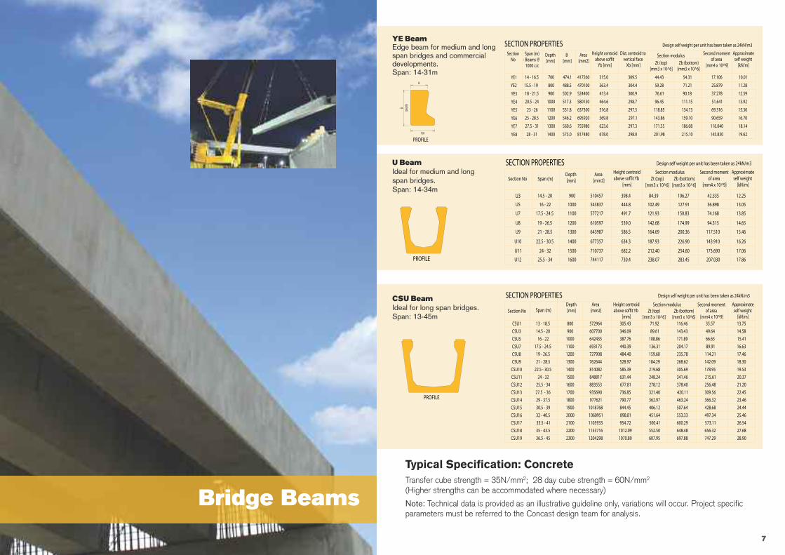
CSU BeamIdeal for long span bridgesSpan: 13-45m
U BeamIdeal for medium and long span bridgesSpans: 14 - 34 m
Y BeamIdeal for medium and long span bridges and commercial developmentsSpan: 14-31m
PROFILE
PROFILE
PROFILE
Section NoDepth [mm]
Area [mm2]
Height centroid above soffit Yb
[mm]Zt (top)
[mm3 x 10^6]
Approximate self weight
[kN/m]
SECTION PROPERTIES Design self weight per unit has been taken as 24kN/m3
Section modulusZb (bottom)
[mm3 x 10^6]
Second moment of area
[mm4 x 10^9]
U3 900
U5
U7
U8
U9
U10
U11
1000
1100
1200
1300
1400
1500
510457
543837
577217
610597
643987
677357
710737
398.4
444.8
491.7
539.0
586.5
634.3
682.2
12.25
13.05
13.85
14.65
15.46
16.26
17.06
84.39 106.27
102.49 127.91
121.93 150.83
142.68 174.99
164.69 200.36
187.93 226.90
212.40 254.60
U12 1600 744117 730.4 17.86238.07 283.45
42.335
56.898
74.168
94.315
117.510
143.910
173.690
207.030
Span (m)
14.5 - 20
16 - 22
17.5 - 24.5
19 - 26.5
21 - 28.5
22.5 - 30.5
24 - 32
25.5 - 34
Section NoDepth [mm]
Area [mm2]
Height centroid above soffit Yb
[mm]Zt (top)
[mm3 x 10^6]
Approximate self weight
[kN/m]
900
1000
1100
1200
1300
1400
607700
642435
693173
727908
762644
814082
SECTION PROPERTIES Design self weight per unit has been taken as 24kN/m3
346.09
387.76
440.39
484.40
528.97
585.39
14.58
15.41
16.63
17.46
18.30
19.53
89.61 143.43
108.86 171.89
136.31 204.17
159.60 235.78
184.29 268.62
219.68 305.69
Section modulusZb (bottom)
[mm3 x 10^6]
Second moment of area
[mm4 x 10^9]
49.64
66.65
89.91
114.21
142.09
178.95
800 572964 305.43 13.7571.92 116.46 35.57
1500 848817 631.44 20.37248.24 341.46 215.61
1600 883553 677.81 21.20278.12 378.40 256.48
1700 935690 736.85 22.45321.40 420.11 309.56
1800 977621 790.77 23.46362.97 463.24 366.32
1900 1018768 844.45 24.44406.12 507.64 428.68
2000 1060951 898.81 25.46451.64 553.33 497.34
2100 1105933 954.72 26.54500.41 600.29 573.11
2200 1153716 1012.09 27.68552.50 648.48 656.32
2300 1204298 1070.80 28.90607.95 697.88 747.29
CSU3
CSU5
CSU7
CSU8
CSU9
CSU10
CSU1
CSU11
CSU12
CSU13
CSU14
CSU15
CSU16
CSU17
CSU18
CSU19
YE Beam
M BeamProvides voided bridge deck for medium and long span road bridge constructionSpan - 16-29m
TY BeamShort and medium span bridges and commercial developmentsSpan - 5-18m
TYE Beam
Edge beam for medium and long span bridges and commercial developmentsSpan: 14-31m
Edge beam for short and medium span bridges and commercial developmentsSpan - 5-18m
PROFILE
PROFILE
PROFILE
PROFILE
Y1
Section No
Depth [mm]
Area [mm2]
Height centroid above soffit Yb
[mm] Zt (top)[mm3 x 10^6]
Approximate self weight
[kN/m]
700
Y2
Y3
Y4
Y5
Y6
Y7
800
900
1000
1100
1200
310140
340830
374420
410880
450230
492460
537580
SECTION PROPERTIES Design self weight per unit has been taken as 24kN/m3
255.0
298.4
346.8
399.3
455.2
514.0
575.0
7.44
8.18
8.99
9.86
10.81
11.82
12.90
24.88 43.42
35.07 58.96
47.95 76.51
63.63 95.72
82.19 116.40
103.73 138.45
128.35 161.83
Y8 585580 637.8 14.05156.12 186.56
Section modulus
Zb (bottom)[mm3 x 10^6]
Second moment of area
[mm4 x 10^9]
11.073
17.593
26.530
38.220
52.990
71.160
93.052
118.990
B [mm]
198.1
227.0
255.8
284.7
313.5
342.3
371.2
400.0
1300
1400
Depth [mm]
Area [mm2]
Height centroid above soffit
Yb [mm] Zt (top)[mm3 x 10^6]
Approximate self weight
[kN/m]
700
800
900
1000
1100
1200
417260
470100
524400
580130
637300
695920
755980
SECTION PROPERTIES Design self weight per unit has been taken as 24kN/m3
315.0
363.4
413.4
464.6
516.8
569.8
623.6
10.01
11.28
12.59
13.92
15.30
16.70
18.14
44.43 54.31
59.28 71.21
76.61 90.18
96.45 111.15
118.85 134.13
143.86 159.10
171.55 186.08
817480 678.0 19.62201.98 215.10
Section modulus
Zb (bottom)[mm3 x 10^6]
Second moment of area
[mm4 x 10^9]
17.106
25.879
37.278
51.641
69.316
90.659
116.040
145.830
B [mm]
474.1
488.5
502.9
517.3
531.8
546.2
560.6
575.0
1300
1400
YE1
YE2
YE3
YE4
YE5
YE6
YE7
YE8
Dist. centroid to vertical face
Xb [mm]
309.5
304.4
300.9
298.7
297.5
297.1
297.3
298.0
M2
Section No.
Depth [mm]
Area [mm2]
Height centroid above soffit Yb
[mm] Zt (top)[mm3 x 10^6]
Approximate self weight
[kN/m]
720
M3
M4
M5
M6
M7
M8
800
880
960
1040
1120
316650
348650
380650
355050
387050
419050
393450
SECTION PROPERTIES Design self weight per unit has been taken as 24kN/m3
265.4
309.8
353.4
357.0
409.2
459.6
454.1
7.60
8.37
9.14
8.52
9.29
10.06
9.44
35.64 61.04
46.96 74.32
58.76 87.56
59.39 100.33
75.39 116.23
91.52 131.53
87.39 143.57
M9 425450 512.3 10.21108.09 161.96
Section modulus
Zb (bottom)[mm3 x 10^6]
Second moment of area
[mm4 x 10^9]
16.202
23.020
30.944
35.813
47.559
60.446
65.187
82.977
Web Height
200
440
1200
1280
457450 568.0 10.98128.65 179.36 101.8801360M10
H [mm]
200
200
440
440
680
680
680
TY1
Section No
Depth [mm]
Area [mm2]
Height centroid above soffit Yb
[mm] Zt (top)[mm3 x 10^6]
Approximate self weight
[kN/m]
400TY2TY3TY4TY5TY6TY7
450500550600650700
188663200046212444225858240288255733272194
SECTION PROPERTIES Design self weight per unit has been taken as 24kN/m3
145.5161.4179.7200.2222.7247.0272.9
4.534.805.105.435.776.146.54
7.69 13.469.71 17.35
12.35 22.0015.62 27.2819.54 33.1024.14 39.3829.42 46.04
TY8 750 289671 300.2 6.9635.41 53.06TY9 800 308163 328.6 7.4042.11 60.40
TY10 850 327671 358.2 7.8749.56 68.05TY11 900 348244 388.6 8.3657.76 76.01
Section modulus
Zb (bottom)[mm3 x 10^6]
Second moment of area
[mm4 x 10^9]
1.95812.80113.95385.46307.37309.726612.56515.92619.85124.37529.539
B [mm]
218238258279299319339360380400421
D
(dep
th)
B
D
(dep
th)
B
750
750
D
(dep
th)
400
H
970
D
(dep
th)
750
750
D
(dep
th)
B
B
Typical Specification
BRIDGE BEAM Section Properties
ConcreteTransfer cube strength = 35 N/mm2.28 day cube strength = 60 N/mm2.(Higher strengths can be accommodated where necessary)
CementCement usually complies with B. S. 12 - Portland.The following may also be used:B. S. 3892 - p.f.a.
AggregatesComply with B. S. 882 - Concrete aggregates from Natural Sources.
Prestressing StrandsComply with B. S. 5896 with Class 2 relaxation.15.7mm dia. standard at 209 kN max. initial force
TolerancesUnless specifically agreed otherwise, beams will be made to the full tolerances shown in DTp specification. Clause 1710.8 (or B.S. 8110 Part 1, Clause 6.11.3 and 6.11.4).
BearingsBearings for bridge beams should be considered on the merits of each particular application. As a general rule however, the edge of the bearing closest to the abutment should be detailed at least 125mm in from the end of the beam (See sketch below). Cast in items cannot project below the soffit line of prestressed units.
WeightThe customer should assume a concrete density of 2.5t / m3.
Quality ControlWe carry out strict quality control procedures at all stages of manufacture. Copies of all necessary certificates on cement, aggregates, strands, stressing records, cube tests and beam tests are retained within our quality system.
125
Span (m)
14.5 - 20
16 - 22
17.5 - 24.5
19 - 26.5
21 - 28.5
22.5 - 30.5
13 - 18.5
24 - 32
25.5 - 34
27.5 - 36
29 - 37.5
30.5 - 39
32 - 40.5
33.5 - 41
35 - 43.5
36.5 - 45
Section No.
Depth [mm]
Area [mm2]
Zt (top)[mm3 x 10^6]
Approximate self weight
[kN/m]
SECTION PROPERTIES Design self weight per unit has been taken as 24kN/m3
Section modulus
Zb (bottom)[mm3 x 10^6]
Second moment of area
[mm4 x 10^9]
B [mm]
317.3310.6
305.4301.4298.2295.8294.1
5.866.45
7.057.658.288.929.56
14.23 17.5418.07 22.28
22.54 27.6027.62 33.4533.31 39.8139.62 46.6846.54 54.04
292.8 10.2254.09 61.88292.0 10.8962.27 70.21291.6 11.5871.10 79.03291.5 12.2780.59 88.33
3.14204.4905
6.20358.3207
10.882013.92917.50321.64626.40131.81437.928
484
494
504514525535545
244080
268520
293470318920344880371350398330
555 425810565 453800575 482290585 511300
TYE1TYE2TYE3TYE4TYE5TYE6TYE7TYE8TYE9TYE10TYE11
400450500
550600650700750800850900
Height centroid above soffit
Yb [mm]
Dist. centroid to vertical face
Xb [mm]
179.2201.6
224.8248.8273.3298.4323.9349.8376.0402.6429.4
Span (m)- Beams @
1000 c/c
14 - 16.5
15.5 - 19
18 - 21.5
20.5 - 24
23 - 26
25 - 28.5
27.5 - 31
28 - 31
Section No
Span (m)- Beams @
1000 c/c
14 - 16.5
15.5 - 19
18 - 21.5
20.5 - 24
23 - 26
25 - 28.5
27.5 - 31
28 - 31
Span
16 - 18
17.5 - 19.5
19 - 21
20.5 - 22.5
22 - 24
23.5 - 26
25 - 27
26.5 - 28.5
27 - 29
Span [m]
4.5 - 8.57.5 - 9.5
8.5 - 10.59.5 - 11.5
10.5 - 12.511.5 - 13.512.5 - 14.513.5 - 15.514.5 - 16.515.5 - 17.5
16 - 18
Span [m]
4.5 - 8.57.5 - 9.5
8.5 - 10.59.5 - 11.5
10.5 - 12.511.5 - 13.512.5 - 14.513.5 - 15.514.5 - 16.515.5 - 17.5
16 - 18
TY BeamShort and medium spanbridges and commericaldevelopments. Span - 5-18m
M BeamProvides voided bridge deck formedium and long span roadbridge construction.Span: 16-29m
CSU BeamIdeal for long span bridgesSpan: 13-45m
U BeamIdeal for medium and long span bridgesSpans: 14 - 34 m
Y BeamIdeal for medium and long span bridges and commercial developmentsSpan: 14-31m
PROFILE
PROFILE
PROFILE
Section NoDepth [mm]
Area [mm2]
Height centroid above soffit Yb
[mm]Zt (top)
[mm3 x 10^6]
Approximate self weight
[kN/m]
SECTION PROPERTIES Design self weight per unit has been taken as 24kN/m3
Section modulusZb (bottom)
[mm3 x 10^6]
Second moment of area
[mm4 x 10^9]
U3 900
U5
U7
U8
U9
U10
U11
1000
1100
1200
1300
1400
1500
510457
543837
577217
610597
643987
677357
710737
398.4
444.8
491.7
539.0
586.5
634.3
682.2
12.25
13.05
13.85
14.65
15.46
16.26
17.06
84.39 106.27
102.49 127.91
121.93 150.83
142.68 174.99
164.69 200.36
187.93 226.90
212.40 254.60
U12 1600 744117 730.4 17.86238.07 283.45
42.335
56.898
74.168
94.315
117.510
143.910
173.690
207.030
Span (m)
14.5 - 20
16 - 22
17.5 - 24.5
19 - 26.5
21 - 28.5
22.5 - 30.5
24 - 32
25.5 - 34
Section NoDepth [mm]
Area [mm2]
Height centroid above soffit Yb
[mm]Zt (top)
[mm3 x 10^6]
Approximate self weight
[kN/m]
900
1000
1100
1200
1300
1400
607700
642435
693173
727908
762644
814082
SECTION PROPERTIES Design self weight per unit has been taken as 24kN/m3
346.09
387.76
440.39
484.40
528.97
585.39
14.58
15.41
16.63
17.46
18.30
19.53
89.61 143.43
108.86 171.89
136.31 204.17
159.60 235.78
184.29 268.62
219.68 305.69
Section modulusZb (bottom)
[mm3 x 10^6]
Second moment of area
[mm4 x 10^9]
49.64
66.65
89.91
114.21
142.09
178.95
800 572964 305.43 13.7571.92 116.46 35.57
1500 848817 631.44 20.37248.24 341.46 215.61
1600 883553 677.81 21.20278.12 378.40 256.48
1700 935690 736.85 22.45321.40 420.11 309.56
1800 977621 790.77 23.46362.97 463.24 366.32
1900 1018768 844.45 24.44406.12 507.64 428.68
2000 1060951 898.81 25.46451.64 553.33 497.34
2100 1105933 954.72 26.54500.41 600.29 573.11
2200 1153716 1012.09 27.68552.50 648.48 656.32
2300 1204298 1070.80 28.90607.95 697.88 747.29
CSU3
CSU5
CSU7
CSU8
CSU9
CSU10
CSU1
CSU11
CSU12
CSU13
CSU14
CSU15
CSU16
CSU17
CSU18
CSU19
YE Beam
M BeamProvides voided bridge deck for medium and long span road bridge constructionSpan - 16-29m
TY BeamShort and medium span bridges and commercial developmentsSpan - 5-18m
TYE Beam
Edge beam for medium and long span bridges and commercial developmentsSpan: 14-31m
Edge beam for short and medium span bridges and commercial developmentsSpan - 5-18m
PROFILE
PROFILE
PROFILE
PROFILE
Y1
Section No
Depth [mm]
Area [mm2]
Height centroid above soffit Yb
[mm] Zt (top)[mm3 x 10^6]
Approximate self weight
[kN/m]
700
Y2
Y3
Y4
Y5
Y6
Y7
800
900
1000
1100
1200
310140
340830
374420
410880
450230
492460
537580
SECTION PROPERTIES Design self weight per unit has been taken as 24kN/m3
255.0
298.4
346.8
399.3
455.2
514.0
575.0
7.44
8.18
8.99
9.86
10.81
11.82
12.90
24.88 43.42
35.07 58.96
47.95 76.51
63.63 95.72
82.19 116.40
103.73 138.45
128.35 161.83
Y8 585580 637.8 14.05156.12 186.56
Section modulus
Zb (bottom)[mm3 x 10^6]
Second moment of area
[mm4 x 10^9]
11.073
17.593
26.530
38.220
52.990
71.160
93.052
118.990
B [mm]
198.1
227.0
255.8
284.7
313.5
342.3
371.2
400.0
1300
1400
Depth [mm]
Area [mm2]
Height centroid above soffit
Yb [mm] Zt (top)[mm3 x 10^6]
Approximate self weight
[kN/m]
700
800
900
1000
1100
1200
417260
470100
524400
580130
637300
695920
755980
SECTION PROPERTIES Design self weight per unit has been taken as 24kN/m3
315.0
363.4
413.4
464.6
516.8
569.8
623.6
10.01
11.28
12.59
13.92
15.30
16.70
18.14
44.43 54.31
59.28 71.21
76.61 90.18
96.45 111.15
118.85 134.13
143.86 159.10
171.55 186.08
817480 678.0 19.62201.98 215.10
Section modulus
Zb (bottom)[mm3 x 10^6]
Second moment of area
[mm4 x 10^9]
17.106
25.879
37.278
51.641
69.316
90.659
116.040
145.830
B [mm]
474.1
488.5
502.9
517.3
531.8
546.2
560.6
575.0
1300
1400
YE1
YE2
YE3
YE4
YE5
YE6
YE7
YE8
Dist. centroid to vertical face
Xb [mm]
309.5
304.4
300.9
298.7
297.5
297.1
297.3
298.0
M2
Section No.
Depth [mm]
Area [mm2]
Height centroid above soffit Yb
[mm] Zt (top)[mm3 x 10^6]
Approximate self weight
[kN/m]
720
M3
M4
M5
M6
M7
M8
800
880
960
1040
1120
316650
348650
380650
355050
387050
419050
393450
SECTION PROPERTIES Design self weight per unit has been taken as 24kN/m3
265.4
309.8
353.4
357.0
409.2
459.6
454.1
7.60
8.37
9.14
8.52
9.29
10.06
9.44
35.64 61.04
46.96 74.32
58.76 87.56
59.39 100.33
75.39 116.23
91.52 131.53
87.39 143.57
M9 425450 512.3 10.21108.09 161.96
Section modulus
Zb (bottom)[mm3 x 10^6]
Second moment of area
[mm4 x 10^9]
16.202
23.020
30.944
35.813
47.559
60.446
65.187
82.977
Web Height
200
440
1200
1280
457450 568.0 10.98128.65 179.36 101.8801360M10
H [mm]
200
200
440
440
680
680
680
TY1
Section No
Depth [mm]
Area [mm2]
Height centroid above soffit Yb
[mm] Zt (top)[mm3 x 10^6]
Approximate self weight
[kN/m]
400TY2TY3TY4TY5TY6TY7
450500550600650700
188663200046212444225858240288255733272194
SECTION PROPERTIES Design self weight per unit has been taken as 24kN/m3
145.5161.4179.7200.2222.7247.0272.9
4.534.805.105.435.776.146.54
7.69 13.469.71 17.35
12.35 22.0015.62 27.2819.54 33.1024.14 39.3829.42 46.04
TY8 750 289671 300.2 6.9635.41 53.06TY9 800 308163 328.6 7.4042.11 60.40
TY10 850 327671 358.2 7.8749.56 68.05TY11 900 348244 388.6 8.3657.76 76.01
Section modulus
Zb (bottom)[mm3 x 10^6]
Second moment of area
[mm4 x 10^9]
1.95812.80113.95385.46307.37309.726612.56515.92619.85124.37529.539
B [mm]
218238258279299319339360380400421
D
(dep
th)
B
D
(dep
th)
B
750
750
D
(dep
th)
400
H
970
D
(dep
th)
750
750
D
(dep
th)
B
B
Typical Specification
BRIDGE BEAM Section Properties
ConcreteTransfer cube strength = 35 N/mm2.28 day cube strength = 60 N/mm2.(Higher strengths can be accommodated where necessary)
CementCement usually complies with B. S. 12 - Portland.The following may also be used:B. S. 3892 - p.f.a.
AggregatesComply with B. S. 882 - Concrete aggregates from Natural Sources.
Prestressing StrandsComply with B. S. 5896 with Class 2 relaxation.15.7mm dia. standard at 209 kN max. initial force
TolerancesUnless specifically agreed otherwise, beams will be made to the full tolerances shown in DTp specification. Clause 1710.8 (or B.S. 8110 Part 1, Clause 6.11.3 and 6.11.4).
BearingsBearings for bridge beams should be considered on the merits of each particular application. As a general rule however, the edge of the bearing closest to the abutment should be detailed at least 125mm in from the end of the beam (See sketch below). Cast in items cannot project below the soffit line of prestressed units.
WeightThe customer should assume a concrete density of 2.5t / m3.
Quality ControlWe carry out strict quality control procedures at all stages of manufacture. Copies of all necessary certificates on cement, aggregates, strands, stressing records, cube tests and beam tests are retained within our quality system.
125
Span (m)
14.5 - 20
16 - 22
17.5 - 24.5
19 - 26.5
21 - 28.5
22.5 - 30.5
13 - 18.5
24 - 32
25.5 - 34
27.5 - 36
29 - 37.5
30.5 - 39
32 - 40.5
33.5 - 41
35 - 43.5
36.5 - 45
Section No.
Depth [mm]
Area [mm2]
Zt (top)[mm3 x 10^6]
Approximate self weight
[kN/m]
SECTION PROPERTIES Design self weight per unit has been taken as 24kN/m3
Section modulus
Zb (bottom)[mm3 x 10^6]
Second moment of area
[mm4 x 10^9]
B [mm]
317.3310.6
305.4301.4298.2295.8294.1
5.866.45
7.057.658.288.929.56
14.23 17.5418.07 22.28
22.54 27.6027.62 33.4533.31 39.8139.62 46.6846.54 54.04
292.8 10.2254.09 61.88292.0 10.8962.27 70.21291.6 11.5871.10 79.03291.5 12.2780.59 88.33
3.14204.4905
6.20358.3207
10.882013.92917.50321.64626.40131.81437.928
484
494
504514525535545
244080
268520
293470318920344880371350398330
555 425810565 453800575 482290585 511300
TYE1TYE2TYE3TYE4TYE5TYE6TYE7TYE8TYE9TYE10TYE11
400450500
550600650700750800850900
Height centroid above soffit
Yb [mm]
Dist. centroid to vertical face
Xb [mm]
179.2201.6
224.8248.8273.3298.4323.9349.8376.0402.6429.4
Span (m)- Beams @
1000 c/c
14 - 16.5
15.5 - 19
18 - 21.5
20.5 - 24
23 - 26
25 - 28.5
27.5 - 31
28 - 31
Section No
Span (m)- Beams @
1000 c/c
14 - 16.5
15.5 - 19
18 - 21.5
20.5 - 24
23 - 26
25 - 28.5
27.5 - 31
28 - 31
Span
16 - 18
17.5 - 19.5
19 - 21
20.5 - 22.5
22 - 24
23.5 - 26
25 - 27
26.5 - 28.5
27 - 29
Span [m]
4.5 - 8.57.5 - 9.5
8.5 - 10.59.5 - 11.5
10.5 - 12.511.5 - 13.512.5 - 14.513.5 - 15.514.5 - 16.515.5 - 17.5
16 - 18
Span [m]
4.5 - 8.57.5 - 9.5
8.5 - 10.59.5 - 11.5
10.5 - 12.511.5 - 13.512.5 - 14.513.5 - 15.514.5 - 16.515.5 - 17.5
16 - 18
TY BeamShort and medium spanbridges and commericaldevelopments. Span - 5-18m
Y BeamIdeal for medium and long spanbridges and commercialdevelopments.Span 14-31m
6
CSU BeamIdeal for long span bridgesSpan: 13-45m
U BeamIdeal for medium and long span bridgesSpans: 14 - 34 m
Y BeamIdeal for medium and long span bridges and commercial developmentsSpan: 14-31m
PROFILE
PROFILE
PROFILE
Section NoDepth [mm]
Area [mm2]
Height centroid above soffit Yb
[mm]Zt (top)
[mm3 x 10^6]
Approximate self weight
[kN/m]
SECTION PROPERTIES Design self weight per unit has been taken as 24kN/m3
Section modulusZb (bottom)
[mm3 x 10^6]
Second moment of area
[mm4 x 10^9]
U3 900
U5
U7
U8
U9
U10
U11
1000
1100
1200
1300
1400
1500
510457
543837
577217
610597
643987
677357
710737
398.4
444.8
491.7
539.0
586.5
634.3
682.2
12.25
13.05
13.85
14.65
15.46
16.26
17.06
84.39 106.27
102.49 127.91
121.93 150.83
142.68 174.99
164.69 200.36
187.93 226.90
212.40 254.60
U12 1600 744117 730.4 17.86238.07 283.45
42.335
56.898
74.168
94.315
117.510
143.910
173.690
207.030
Span (m)
14.5 - 20
16 - 22
17.5 - 24.5
19 - 26.5
21 - 28.5
22.5 - 30.5
24 - 32
25.5 - 34
Section NoDepth [mm]
Area [mm2]
Height centroid above soffit Yb
[mm]Zt (top)
[mm3 x 10^6]
Approximate self weight
[kN/m]
900
1000
1100
1200
1300
1400
607700
642435
693173
727908
762644
814082
SECTION PROPERTIES Design self weight per unit has been taken as 24kN/m3
346.09
387.76
440.39
484.40
528.97
585.39
14.58
15.41
16.63
17.46
18.30
19.53
89.61 143.43
108.86 171.89
136.31 204.17
159.60 235.78
184.29 268.62
219.68 305.69
Section modulusZb (bottom)
[mm3 x 10^6]
Second moment of area
[mm4 x 10^9]
49.64
66.65
89.91
114.21
142.09
178.95
800 572964 305.43 13.7571.92 116.46 35.57
1500 848817 631.44 20.37248.24 341.46 215.61
1600 883553 677.81 21.20278.12 378.40 256.48
1700 935690 736.85 22.45321.40 420.11 309.56
1800 977621 790.77 23.46362.97 463.24 366.32
1900 1018768 844.45 24.44406.12 507.64 428.68
2000 1060951 898.81 25.46451.64 553.33 497.34
2100 1105933 954.72 26.54500.41 600.29 573.11
2200 1153716 1012.09 27.68552.50 648.48 656.32
2300 1204298 1070.80 28.90607.95 697.88 747.29
CSU3
CSU5
CSU7
CSU8
CSU9
CSU10
CSU1
CSU11
CSU12
CSU13
CSU14
CSU15
CSU16
CSU17
CSU18
CSU19
YE Beam
M BeamProvides voided bridge deck for medium and long span road bridge constructionSpan - 16-29m
TY BeamShort and medium span bridges and commercial developmentsSpan - 5-18m
TYE Beam
Edge beam for medium and long span bridges and commercial developmentsSpan: 14-31m
Edge beam for short and medium span bridges and commercial developmentsSpan - 5-18m
PROFILE
PROFILE
PROFILE
PROFILE
Y1
Section No
Depth [mm]
Area [mm2]
Height centroid above soffit Yb
[mm] Zt (top)[mm3 x 10^6]
Approximate self weight
[kN/m]
700
Y2
Y3
Y4
Y5
Y6
Y7
800
900
1000
1100
1200
310140
340830
374420
410880
450230
492460
537580
SECTION PROPERTIES Design self weight per unit has been taken as 24kN/m3
255.0
298.4
346.8
399.3
455.2
514.0
575.0
7.44
8.18
8.99
9.86
10.81
11.82
12.90
24.88 43.42
35.07 58.96
47.95 76.51
63.63 95.72
82.19 116.40
103.73 138.45
128.35 161.83
Y8 585580 637.8 14.05156.12 186.56
Section modulus
Zb (bottom)[mm3 x 10^6]
Second moment of area
[mm4 x 10^9]
11.073
17.593
26.530
38.220
52.990
71.160
93.052
118.990
B [mm]
198.1
227.0
255.8
284.7
313.5
342.3
371.2
400.0
1300
1400
Depth [mm]
Area [mm2]
Height centroid above soffit
Yb [mm] Zt (top)[mm3 x 10^6]
Approximate self weight
[kN/m]
700
800
900
1000
1100
1200
417260
470100
524400
580130
637300
695920
755980
SECTION PROPERTIES Design self weight per unit has been taken as 24kN/m3
315.0
363.4
413.4
464.6
516.8
569.8
623.6
10.01
11.28
12.59
13.92
15.30
16.70
18.14
44.43 54.31
59.28 71.21
76.61 90.18
96.45 111.15
118.85 134.13
143.86 159.10
171.55 186.08
817480 678.0 19.62201.98 215.10
Section modulus
Zb (bottom)[mm3 x 10^6]
Second moment of area
[mm4 x 10^9]
17.106
25.879
37.278
51.641
69.316
90.659
116.040
145.830
B [mm]
474.1
488.5
502.9
517.3
531.8
546.2
560.6
575.0
1300
1400
YE1
YE2
YE3
YE4
YE5
YE6
YE7
YE8
Dist. centroid to vertical face
Xb [mm]
309.5
304.4
300.9
298.7
297.5
297.1
297.3
298.0
M2
Section No.
Depth [mm]
Area [mm2]
Height centroid above soffit Yb
[mm] Zt (top)[mm3 x 10^6]
Approximate self weight
[kN/m]
720
M3
M4
M5
M6
M7
M8
800
880
960
1040
1120
316650
348650
380650
355050
387050
419050
393450
SECTION PROPERTIES Design self weight per unit has been taken as 24kN/m3
265.4
309.8
353.4
357.0
409.2
459.6
454.1
7.60
8.37
9.14
8.52
9.29
10.06
9.44
35.64 61.04
46.96 74.32
58.76 87.56
59.39 100.33
75.39 116.23
91.52 131.53
87.39 143.57
M9 425450 512.3 10.21108.09 161.96
Section modulus
Zb (bottom)[mm3 x 10^6]
Second moment of area
[mm4 x 10^9]
16.202
23.020
30.944
35.813
47.559
60.446
65.187
82.977
Web Height
200
440
1200
1280
457450 568.0 10.98128.65 179.36 101.8801360M10
H [mm]
200
200
440
440
680
680
680
TY1
Section No
Depth [mm]
Area [mm2]
Height centroid above soffit Yb
[mm] Zt (top)[mm3 x 10^6]
Approximate self weight
[kN/m]
400TY2TY3TY4TY5TY6TY7
450500550600650700
188663200046212444225858240288255733272194
SECTION PROPERTIES Design self weight per unit has been taken as 24kN/m3
145.5161.4179.7200.2222.7247.0272.9
4.534.805.105.435.776.146.54
7.69 13.469.71 17.35
12.35 22.0015.62 27.2819.54 33.1024.14 39.3829.42 46.04
TY8 750 289671 300.2 6.9635.41 53.06TY9 800 308163 328.6 7.4042.11 60.40
TY10 850 327671 358.2 7.8749.56 68.05TY11 900 348244 388.6 8.3657.76 76.01
Section modulus
Zb (bottom)[mm3 x 10^6]
Second moment of area
[mm4 x 10^9]
1.95812.80113.95385.46307.37309.726612.56515.92619.85124.37529.539
B [mm]
218238258279299319339360380400421
D
(dep
th)
B
D
(dep
th)
B
750
750
D
(dep
th)
400
H
970
D
(dep
th)
750
750
D
(dep
th)
B
B
Typical Specification
BRIDGE BEAM Section Properties
ConcreteTransfer cube strength = 35 N/mm2.28 day cube strength = 60 N/mm2.(Higher strengths can be accommodated where necessary)
CementCement usually complies with B. S. 12 - Portland.The following may also be used:B. S. 3892 - p.f.a.
AggregatesComply with B. S. 882 - Concrete aggregates from Natural Sources.
Prestressing StrandsComply with B. S. 5896 with Class 2 relaxation.15.7mm dia. standard at 209 kN max. initial force
TolerancesUnless specifically agreed otherwise, beams will be made to the full tolerances shown in DTp specification. Clause 1710.8 (or B.S. 8110 Part 1, Clause 6.11.3 and 6.11.4).
BearingsBearings for bridge beams should be considered on the merits of each particular application. As a general rule however, the edge of the bearing closest to the abutment should be detailed at least 125mm in from the end of the beam (See sketch below). Cast in items cannot project below the soffit line of prestressed units.
WeightThe customer should assume a concrete density of 2.5t / m3.
Quality ControlWe carry out strict quality control procedures at all stages of manufacture. Copies of all necessary certificates on cement, aggregates, strands, stressing records, cube tests and beam tests are retained within our quality system.
125
Span (m)
14.5 - 20
16 - 22
17.5 - 24.5
19 - 26.5
21 - 28.5
22.5 - 30.5
13 - 18.5
24 - 32
25.5 - 34
27.5 - 36
29 - 37.5
30.5 - 39
32 - 40.5
33.5 - 41
35 - 43.5
36.5 - 45
Section No.
Depth [mm]
Area [mm2]
Zt (top)[mm3 x 10^6]
Approximate self weight
[kN/m]
SECTION PROPERTIES Design self weight per unit has been taken as 24kN/m3
Section modulus
Zb (bottom)[mm3 x 10^6]
Second moment of area
[mm4 x 10^9]
B [mm]
317.3310.6
305.4301.4298.2295.8294.1
5.866.45
7.057.658.288.929.56
14.23 17.5418.07 22.28
22.54 27.6027.62 33.4533.31 39.8139.62 46.6846.54 54.04
292.8 10.2254.09 61.88292.0 10.8962.27 70.21291.6 11.5871.10 79.03291.5 12.2780.59 88.33
3.14204.4905
6.20358.3207
10.882013.92917.50321.64626.40131.81437.928
484
494
504514525535545
244080
268520
293470318920344880371350398330
555 425810565 453800575 482290585 511300
TYE1TYE2TYE3TYE4TYE5TYE6TYE7TYE8TYE9TYE10TYE11
400450500
550600650700750800850900
Height centroid above soffit
Yb [mm]
Dist. centroid to vertical face
Xb [mm]
179.2201.6
224.8248.8273.3298.4323.9349.8376.0402.6429.4
Span (m)- Beams @
1000 c/c
14 - 16.5
15.5 - 19
18 - 21.5
20.5 - 24
23 - 26
25 - 28.5
27.5 - 31
28 - 31
Section No
Span (m)- Beams @
1000 c/c
14 - 16.5
15.5 - 19
18 - 21.5
20.5 - 24
23 - 26
25 - 28.5
27.5 - 31
28 - 31
Span
16 - 18
17.5 - 19.5
19 - 21
20.5 - 22.5
22 - 24
23.5 - 26
25 - 27
26.5 - 28.5
27 - 29
Span [m]
4.5 - 8.57.5 - 9.5
8.5 - 10.59.5 - 11.5
10.5 - 12.511.5 - 13.512.5 - 14.513.5 - 15.514.5 - 16.515.5 - 17.5
16 - 18
Span [m]
4.5 - 8.57.5 - 9.5
8.5 - 10.59.5 - 11.5
10.5 - 12.511.5 - 13.512.5 - 14.513.5 - 15.514.5 - 16.515.5 - 17.5
16 - 18
TY BeamShort and medium spanbridges and commericaldevelopments. Span - 5-18m
YE BeamEdge beam for medium and longspan bridges and commercialdevelopments.Span: 14-31m
CSU BeamIdeal for long span bridgesSpan: 13-45m
U BeamIdeal for medium and long span bridgesSpans: 14 - 34 m
Y BeamIdeal for medium and long span bridges and commercial developmentsSpan: 14-31m
PROFILE
PROFILE
PROFILE
Section NoDepth [mm]
Area [mm2]
Height centroid above soffit Yb
[mm]Zt (top)
[mm3 x 10^6]
Approximate self weight
[kN/m]
SECTION PROPERTIES Design self weight per unit has been taken as 24kN/m3
Section modulusZb (bottom)
[mm3 x 10^6]
Second moment of area
[mm4 x 10^9]
U3 900
U5
U7
U8
U9
U10
U11
1000
1100
1200
1300
1400
1500
510457
543837
577217
610597
643987
677357
710737
398.4
444.8
491.7
539.0
586.5
634.3
682.2
12.25
13.05
13.85
14.65
15.46
16.26
17.06
84.39 106.27
102.49 127.91
121.93 150.83
142.68 174.99
164.69 200.36
187.93 226.90
212.40 254.60
U12 1600 744117 730.4 17.86238.07 283.45
42.335
56.898
74.168
94.315
117.510
143.910
173.690
207.030
Span (m)
14.5 - 20
16 - 22
17.5 - 24.5
19 - 26.5
21 - 28.5
22.5 - 30.5
24 - 32
25.5 - 34
Section NoDepth [mm]
Area [mm2]
Height centroid above soffit Yb
[mm]Zt (top)
[mm3 x 10^6]
Approximate self weight
[kN/m]
900
1000
1100
1200
1300
1400
607700
642435
693173
727908
762644
814082
SECTION PROPERTIES Design self weight per unit has been taken as 24kN/m3
346.09
387.76
440.39
484.40
528.97
585.39
14.58
15.41
16.63
17.46
18.30
19.53
89.61 143.43
108.86 171.89
136.31 204.17
159.60 235.78
184.29 268.62
219.68 305.69
Section modulusZb (bottom)
[mm3 x 10^6]
Second moment of area
[mm4 x 10^9]
49.64
66.65
89.91
114.21
142.09
178.95
800 572964 305.43 13.7571.92 116.46 35.57
1500 848817 631.44 20.37248.24 341.46 215.61
1600 883553 677.81 21.20278.12 378.40 256.48
1700 935690 736.85 22.45321.40 420.11 309.56
1800 977621 790.77 23.46362.97 463.24 366.32
1900 1018768 844.45 24.44406.12 507.64 428.68
2000 1060951 898.81 25.46451.64 553.33 497.34
2100 1105933 954.72 26.54500.41 600.29 573.11
2200 1153716 1012.09 27.68552.50 648.48 656.32
2300 1204298 1070.80 28.90607.95 697.88 747.29
CSU3
CSU5
CSU7
CSU8
CSU9
CSU10
CSU1
CSU11
CSU12
CSU13
CSU14
CSU15
CSU16
CSU17
CSU18
CSU19
YE Beam
M BeamProvides voided bridge deck for medium and long span road bridge constructionSpan - 16-29m
TY BeamShort and medium span bridges and commercial developmentsSpan - 5-18m
TYE Beam
Edge beam for medium and long span bridges and commercial developmentsSpan: 14-31m
Edge beam for short and medium span bridges and commercial developmentsSpan - 5-18m
PROFILE
PROFILE
PROFILE
PROFILE
Y1
Section No
Depth [mm]
Area [mm2]
Height centroid above soffit Yb
[mm] Zt (top)[mm3 x 10^6]
Approximate self weight
[kN/m]
700
Y2
Y3
Y4
Y5
Y6
Y7
800
900
1000
1100
1200
310140
340830
374420
410880
450230
492460
537580
SECTION PROPERTIES Design self weight per unit has been taken as 24kN/m3
255.0
298.4
346.8
399.3
455.2
514.0
575.0
7.44
8.18
8.99
9.86
10.81
11.82
12.90
24.88 43.42
35.07 58.96
47.95 76.51
63.63 95.72
82.19 116.40
103.73 138.45
128.35 161.83
Y8 585580 637.8 14.05156.12 186.56
Section modulus
Zb (bottom)[mm3 x 10^6]
Second moment of area
[mm4 x 10^9]
11.073
17.593
26.530
38.220
52.990
71.160
93.052
118.990
B [mm]
198.1
227.0
255.8
284.7
313.5
342.3
371.2
400.0
1300
1400
Depth [mm]
Area [mm2]
Height centroid above soffit
Yb [mm] Zt (top)[mm3 x 10^6]
Approximate self weight
[kN/m]
700
800
900
1000
1100
1200
417260
470100
524400
580130
637300
695920
755980
SECTION PROPERTIES Design self weight per unit has been taken as 24kN/m3
315.0
363.4
413.4
464.6
516.8
569.8
623.6
10.01
11.28
12.59
13.92
15.30
16.70
18.14
44.43 54.31
59.28 71.21
76.61 90.18
96.45 111.15
118.85 134.13
143.86 159.10
171.55 186.08
817480 678.0 19.62201.98 215.10
Section modulus
Zb (bottom)[mm3 x 10^6]
Second moment of area
[mm4 x 10^9]
17.106
25.879
37.278
51.641
69.316
90.659
116.040
145.830
B [mm]
474.1
488.5
502.9
517.3
531.8
546.2
560.6
575.0
1300
1400
YE1
YE2
YE3
YE4
YE5
YE6
YE7
YE8
Dist. centroid to vertical face
Xb [mm]
309.5
304.4
300.9
298.7
297.5
297.1
297.3
298.0
M2
Section No.
Depth [mm]
Area [mm2]
Height centroid above soffit Yb
[mm] Zt (top)[mm3 x 10^6]
Approximate self weight
[kN/m]
720
M3
M4
M5
M6
M7
M8
800
880
960
1040
1120
316650
348650
380650
355050
387050
419050
393450
SECTION PROPERTIES Design self weight per unit has been taken as 24kN/m3
265.4
309.8
353.4
357.0
409.2
459.6
454.1
7.60
8.37
9.14
8.52
9.29
10.06
9.44
35.64 61.04
46.96 74.32
58.76 87.56
59.39 100.33
75.39 116.23
91.52 131.53
87.39 143.57
M9 425450 512.3 10.21108.09 161.96
Section modulus
Zb (bottom)[mm3 x 10^6]
Second moment of area
[mm4 x 10^9]
16.202
23.020
30.944
35.813
47.559
60.446
65.187
82.977
Web Height
200
440
1200
1280
457450 568.0 10.98128.65 179.36 101.8801360M10
H [mm]
200
200
440
440
680
680
680
TY1
Section No
Depth [mm]
Area [mm2]
Height centroid above soffit Yb
[mm] Zt (top)[mm3 x 10^6]
Approximate self weight
[kN/m]
400TY2TY3TY4TY5TY6TY7
450500550600650700
188663200046212444225858240288255733272194
SECTION PROPERTIES Design self weight per unit has been taken as 24kN/m3
145.5161.4179.7200.2222.7247.0272.9
4.534.805.105.435.776.146.54
7.69 13.469.71 17.35
12.35 22.0015.62 27.2819.54 33.1024.14 39.3829.42 46.04
TY8 750 289671 300.2 6.9635.41 53.06TY9 800 308163 328.6 7.4042.11 60.40
TY10 850 327671 358.2 7.8749.56 68.05TY11 900 348244 388.6 8.3657.76 76.01
Section modulus
Zb (bottom)[mm3 x 10^6]
Second moment of area
[mm4 x 10^9]
1.95812.80113.95385.46307.37309.726612.56515.92619.85124.37529.539
B [mm]
218238258279299319339360380400421
D
(dep
th)
B
D
(dep
th)
B
750
750
D
(dep
th)
400
H
970
D
(dep
th)
750
750
D
(dep
th)
B
B
Typical Specification
BRIDGE BEAM Section Properties
ConcreteTransfer cube strength = 35 N/mm2.28 day cube strength = 60 N/mm2.(Higher strengths can be accommodated where necessary)
CementCement usually complies with B. S. 12 - Portland.The following may also be used:B. S. 3892 - p.f.a.
AggregatesComply with B. S. 882 - Concrete aggregates from Natural Sources.
Prestressing StrandsComply with B. S. 5896 with Class 2 relaxation.15.7mm dia. standard at 209 kN max. initial force
TolerancesUnless specifically agreed otherwise, beams will be made to the full tolerances shown in DTp specification. Clause 1710.8 (or B.S. 8110 Part 1, Clause 6.11.3 and 6.11.4).
BearingsBearings for bridge beams should be considered on the merits of each particular application. As a general rule however, the edge of the bearing closest to the abutment should be detailed at least 125mm in from the end of the beam (See sketch below). Cast in items cannot project below the soffit line of prestressed units.
WeightThe customer should assume a concrete density of 2.5t / m3.
Quality ControlWe carry out strict quality control procedures at all stages of manufacture. Copies of all necessary certificates on cement, aggregates, strands, stressing records, cube tests and beam tests are retained within our quality system.
125
Span (m)
14.5 - 20
16 - 22
17.5 - 24.5
19 - 26.5
21 - 28.5
22.5 - 30.5
13 - 18.5
24 - 32
25.5 - 34
27.5 - 36
29 - 37.5
30.5 - 39
32 - 40.5
33.5 - 41
35 - 43.5
36.5 - 45
Section No.
Depth [mm]
Area [mm2]
Zt (top)[mm3 x 10^6]
Approximate self weight
[kN/m]
SECTION PROPERTIES Design self weight per unit has been taken as 24kN/m3
Section modulus
Zb (bottom)[mm3 x 10^6]
Second moment of area
[mm4 x 10^9]
B [mm]
317.3310.6
305.4301.4298.2295.8294.1
5.866.45
7.057.658.288.929.56
14.23 17.5418.07 22.28
22.54 27.6027.62 33.4533.31 39.8139.62 46.6846.54 54.04
292.8 10.2254.09 61.88292.0 10.8962.27 70.21291.6 11.5871.10 79.03291.5 12.2780.59 88.33
3.14204.4905
6.20358.3207
10.882013.92917.50321.64626.40131.81437.928
484
494
504514525535545
244080
268520
293470318920344880371350398330
555 425810565 453800575 482290585 511300
TYE1TYE2TYE3TYE4TYE5TYE6TYE7TYE8TYE9TYE10TYE11
400450500
550600650700750800850900
Height centroid above soffit
Yb [mm]
Dist. centroid to vertical face
Xb [mm]
179.2201.6
224.8248.8273.3298.4323.9349.8376.0402.6429.4
Span (m)- Beams @
1000 c/c
14 - 16.5
15.5 - 19
18 - 21.5
20.5 - 24
23 - 26
25 - 28.5
27.5 - 31
28 - 31
Section No
Span (m)- Beams @
1000 c/c
14 - 16.5
15.5 - 19
18 - 21.5
20.5 - 24
23 - 26
25 - 28.5
27.5 - 31
28 - 31
Span
16 - 18
17.5 - 19.5
19 - 21
20.5 - 22.5
22 - 24
23.5 - 26
25 - 27
26.5 - 28.5
27 - 29
Span [m]
4.5 - 8.57.5 - 9.5
8.5 - 10.59.5 - 11.5
10.5 - 12.511.5 - 13.512.5 - 14.513.5 - 15.514.5 - 16.515.5 - 17.5
16 - 18
Span [m]
4.5 - 8.57.5 - 9.5
8.5 - 10.59.5 - 11.5
10.5 - 12.511.5 - 13.512.5 - 14.513.5 - 15.514.5 - 16.515.5 - 17.5
16 - 18
TY BeamShort and medium spanbridges and commericaldevelopments. Span - 5-18m
U BeamIdeal for medium and longspan bridges.Span: 14-34m
CSU BeamIdeal for long span bridgesSpan: 13-45m
U BeamIdeal for medium and long span bridgesSpans: 14 - 34 m
Y BeamIdeal for medium and long span bridges and commercial developmentsSpan: 14-31m
PROFILE
PROFILE
PROFILE
Section NoDepth [mm]
Area [mm2]
Height centroid above soffit Yb
[mm]Zt (top)
[mm3 x 10^6]
Approximate self weight
[kN/m]
SECTION PROPERTIES Design self weight per unit has been taken as 24kN/m3
Section modulusZb (bottom)
[mm3 x 10^6]
Second moment of area
[mm4 x 10^9]
U3 900
U5
U7
U8
U9
U10
U11
1000
1100
1200
1300
1400
1500
510457
543837
577217
610597
643987
677357
710737
398.4
444.8
491.7
539.0
586.5
634.3
682.2
12.25
13.05
13.85
14.65
15.46
16.26
17.06
84.39 106.27
102.49 127.91
121.93 150.83
142.68 174.99
164.69 200.36
187.93 226.90
212.40 254.60
U12 1600 744117 730.4 17.86238.07 283.45
42.335
56.898
74.168
94.315
117.510
143.910
173.690
207.030
Span (m)
14.5 - 20
16 - 22
17.5 - 24.5
19 - 26.5
21 - 28.5
22.5 - 30.5
24 - 32
25.5 - 34
Section NoDepth [mm]
Area [mm2]
Height centroid above soffit Yb
[mm]Zt (top)
[mm3 x 10^6]
Approximate self weight
[kN/m]
900
1000
1100
1200
1300
1400
607700
642435
693173
727908
762644
814082
SECTION PROPERTIES Design self weight per unit has been taken as 24kN/m3
346.09
387.76
440.39
484.40
528.97
585.39
14.58
15.41
16.63
17.46
18.30
19.53
89.61 143.43
108.86 171.89
136.31 204.17
159.60 235.78
184.29 268.62
219.68 305.69
Section modulusZb (bottom)
[mm3 x 10^6]
Second moment of area
[mm4 x 10^9]
49.64
66.65
89.91
114.21
142.09
178.95
800 572964 305.43 13.7571.92 116.46 35.57
1500 848817 631.44 20.37248.24 341.46 215.61
1600 883553 677.81 21.20278.12 378.40 256.48
1700 935690 736.85 22.45321.40 420.11 309.56
1800 977621 790.77 23.46362.97 463.24 366.32
1900 1018768 844.45 24.44406.12 507.64 428.68
2000 1060951 898.81 25.46451.64 553.33 497.34
2100 1105933 954.72 26.54500.41 600.29 573.11
2200 1153716 1012.09 27.68552.50 648.48 656.32
2300 1204298 1070.80 28.90607.95 697.88 747.29
CSU3
CSU5
CSU7
CSU8
CSU9
CSU10
CSU1
CSU11
CSU12
CSU13
CSU14
CSU15
CSU16
CSU17
CSU18
CSU19
YE Beam
M BeamProvides voided bridge deck for medium and long span road bridge constructionSpan - 16-29m
TY BeamShort and medium span bridges and commercial developmentsSpan - 5-18m
TYE Beam
Edge beam for medium and long span bridges and commercial developmentsSpan: 14-31m
Edge beam for short and medium span bridges and commercial developmentsSpan - 5-18m
PROFILE
PROFILE
PROFILE
PROFILE
Y1
Section No
Depth [mm]
Area [mm2]
Height centroid above soffit Yb
[mm] Zt (top)[mm3 x 10^6]
Approximate self weight
[kN/m]
700
Y2
Y3
Y4
Y5
Y6
Y7
800
900
1000
1100
1200
310140
340830
374420
410880
450230
492460
537580
SECTION PROPERTIES Design self weight per unit has been taken as 24kN/m3
255.0
298.4
346.8
399.3
455.2
514.0
575.0
7.44
8.18
8.99
9.86
10.81
11.82
12.90
24.88 43.42
35.07 58.96
47.95 76.51
63.63 95.72
82.19 116.40
103.73 138.45
128.35 161.83
Y8 585580 637.8 14.05156.12 186.56
Section modulus
Zb (bottom)[mm3 x 10^6]
Second moment of area
[mm4 x 10^9]
11.073
17.593
26.530
38.220
52.990
71.160
93.052
118.990
B [mm]
198.1
227.0
255.8
284.7
313.5
342.3
371.2
400.0
1300
1400
Depth [mm]
Area [mm2]
Height centroid above soffit
Yb [mm] Zt (top)[mm3 x 10^6]
Approximate self weight
[kN/m]
700
800
900
1000
1100
1200
417260
470100
524400
580130
637300
695920
755980
SECTION PROPERTIES Design self weight per unit has been taken as 24kN/m3
315.0
363.4
413.4
464.6
516.8
569.8
623.6
10.01
11.28
12.59
13.92
15.30
16.70
18.14
44.43 54.31
59.28 71.21
76.61 90.18
96.45 111.15
118.85 134.13
143.86 159.10
171.55 186.08
817480 678.0 19.62201.98 215.10
Section modulus
Zb (bottom)[mm3 x 10^6]
Second moment of area
[mm4 x 10^9]
17.106
25.879
37.278
51.641
69.316
90.659
116.040
145.830
B [mm]
474.1
488.5
502.9
517.3
531.8
546.2
560.6
575.0
1300
1400
YE1
YE2
YE3
YE4
YE5
YE6
YE7
YE8
Dist. centroid to vertical face
Xb [mm]
309.5
304.4
300.9
298.7
297.5
297.1
297.3
298.0
M2
Section No.
Depth [mm]
Area [mm2]
Height centroid above soffit Yb
[mm] Zt (top)[mm3 x 10^6]
Approximate self weight
[kN/m]
720
M3
M4
M5
M6
M7
M8
800
880
960
1040
1120
316650
348650
380650
355050
387050
419050
393450
SECTION PROPERTIES Design self weight per unit has been taken as 24kN/m3
265.4
309.8
353.4
357.0
409.2
459.6
454.1
7.60
8.37
9.14
8.52
9.29
10.06
9.44
35.64 61.04
46.96 74.32
58.76 87.56
59.39 100.33
75.39 116.23
91.52 131.53
87.39 143.57
M9 425450 512.3 10.21108.09 161.96
Section modulus
Zb (bottom)[mm3 x 10^6]
Second moment of area
[mm4 x 10^9]
16.202
23.020
30.944
35.813
47.559
60.446
65.187
82.977
Web Height
200
440
1200
1280
457450 568.0 10.98128.65 179.36 101.8801360M10
H [mm]
200
200
440
440
680
680
680
TY1
Section No
Depth [mm]
Area [mm2]
Height centroid above soffit Yb
[mm] Zt (top)[mm3 x 10^6]
Approximate self weight
[kN/m]
400TY2TY3TY4TY5TY6TY7
450500550600650700
188663200046212444225858240288255733272194
SECTION PROPERTIES Design self weight per unit has been taken as 24kN/m3
145.5161.4179.7200.2222.7247.0272.9
4.534.805.105.435.776.146.54
7.69 13.469.71 17.35
12.35 22.0015.62 27.2819.54 33.1024.14 39.3829.42 46.04
TY8 750 289671 300.2 6.9635.41 53.06TY9 800 308163 328.6 7.4042.11 60.40
TY10 850 327671 358.2 7.8749.56 68.05TY11 900 348244 388.6 8.3657.76 76.01
Section modulus
Zb (bottom)[mm3 x 10^6]
Second moment of area
[mm4 x 10^9]
1.95812.80113.95385.46307.37309.726612.56515.92619.85124.37529.539
B [mm]
218238258279299319339360380400421
D
(dep
th)
B
D
(dep
th)
B
750
750
D
(dep
th)
400
H
970
D
(dep
th)
750
750
D
(dep
th)
B
B
Typical Specification
BRIDGE BEAM Section Properties
ConcreteTransfer cube strength = 35 N/mm2.28 day cube strength = 60 N/mm2.(Higher strengths can be accommodated where necessary)
CementCement usually complies with B. S. 12 - Portland.The following may also be used:B. S. 3892 - p.f.a.
AggregatesComply with B. S. 882 - Concrete aggregates from Natural Sources.
Prestressing StrandsComply with B. S. 5896 with Class 2 relaxation.15.7mm dia. standard at 209 kN max. initial force
TolerancesUnless specifically agreed otherwise, beams will be made to the full tolerances shown in DTp specification. Clause 1710.8 (or B.S. 8110 Part 1, Clause 6.11.3 and 6.11.4).
BearingsBearings for bridge beams should be considered on the merits of each particular application. As a general rule however, the edge of the bearing closest to the abutment should be detailed at least 125mm in from the end of the beam (See sketch below). Cast in items cannot project below the soffit line of prestressed units.
WeightThe customer should assume a concrete density of 2.5t / m3.
Quality ControlWe carry out strict quality control procedures at all stages of manufacture. Copies of all necessary certificates on cement, aggregates, strands, stressing records, cube tests and beam tests are retained within our quality system.
125
Span (m)
14.5 - 20
16 - 22
17.5 - 24.5
19 - 26.5
21 - 28.5
22.5 - 30.5
13 - 18.5
24 - 32
25.5 - 34
27.5 - 36
29 - 37.5
30.5 - 39
32 - 40.5
33.5 - 41
35 - 43.5
36.5 - 45
Section No.
Depth [mm]
Area [mm2]
Zt (top)[mm3 x 10^6]
Approximate self weight
[kN/m]
SECTION PROPERTIES Design self weight per unit has been taken as 24kN/m3
Section modulus
Zb (bottom)[mm3 x 10^6]
Second moment of area
[mm4 x 10^9]
B [mm]
317.3310.6
305.4301.4298.2295.8294.1
5.866.45
7.057.658.288.929.56
14.23 17.5418.07 22.28
22.54 27.6027.62 33.4533.31 39.8139.62 46.6846.54 54.04
292.8 10.2254.09 61.88292.0 10.8962.27 70.21291.6 11.5871.10 79.03291.5 12.2780.59 88.33
3.14204.4905
6.20358.3207
10.882013.92917.50321.64626.40131.81437.928
484
494
504514525535545
244080
268520
293470318920344880371350398330
555 425810565 453800575 482290585 511300
TYE1TYE2TYE3TYE4TYE5TYE6TYE7TYE8TYE9TYE10TYE11
400450500
550600650700750800850900
Height centroid above soffit
Yb [mm]
Dist. centroid to vertical face
Xb [mm]
179.2201.6
224.8248.8273.3298.4323.9349.8376.0402.6429.4
Span (m)- Beams @
1000 c/c
14 - 16.5
15.5 - 19
18 - 21.5
20.5 - 24
23 - 26
25 - 28.5
27.5 - 31
28 - 31
Section No
Span (m)- Beams @
1000 c/c
14 - 16.5
15.5 - 19
18 - 21.5
20.5 - 24
23 - 26
25 - 28.5
27.5 - 31
28 - 31
Span
16 - 18
17.5 - 19.5
19 - 21
20.5 - 22.5
22 - 24
23.5 - 26
25 - 27
26.5 - 28.5
27 - 29
Span [m]
4.5 - 8.57.5 - 9.5
8.5 - 10.59.5 - 11.5
10.5 - 12.511.5 - 13.512.5 - 14.513.5 - 15.514.5 - 16.515.5 - 17.5
16 - 18
Span [m]
4.5 - 8.57.5 - 9.5
8.5 - 10.59.5 - 11.5
10.5 - 12.511.5 - 13.512.5 - 14.513.5 - 15.514.5 - 16.515.5 - 17.5
16 - 18
TY BeamShort and medium spanbridges and commericaldevelopments. Span - 5-18m
CSU BeamIdeal for long span bridges.Span: 13-45m
7
Typical Specification: ConcreteTransfer cube strength = 35N/mm2; 28 day cube strength = 60N/mm2
(Higher strengths can be accommodated where necessary)
Note: Technical data is provided as an illustrative guideline only, variations will occur. Project specificparameters must be referred to the Concast design team for analysis.
Bridge Beams
CSU BeamIdeal for long span bridgesSpan: 13-45m
U BeamIdeal for medium and long span bridgesSpans: 14 - 34 m
Y BeamIdeal for medium and long span bridges and commercial developmentsSpan: 14-31m
PROFILE
PROFILE
PROFILE
Section NoDepth [mm]
Area [mm2]
Height centroid above soffit Yb
[mm]Zt (top)
[mm3 x 10^6]
Approximate self weight
[kN/m]
SECTION PROPERTIES Design self weight per unit has been taken as 24kN/m3
Section modulusZb (bottom)
[mm3 x 10^6]
Second moment of area
[mm4 x 10^9]
U3 900
U5
U7
U8
U9
U10
U11
1000
1100
1200
1300
1400
1500
510457
543837
577217
610597
643987
677357
710737
398.4
444.8
491.7
539.0
586.5
634.3
682.2
12.25
13.05
13.85
14.65
15.46
16.26
17.06
84.39 106.27
102.49 127.91
121.93 150.83
142.68 174.99
164.69 200.36
187.93 226.90
212.40 254.60
U12 1600 744117 730.4 17.86238.07 283.45
42.335
56.898
74.168
94.315
117.510
143.910
173.690
207.030
Span (m)
14.5 - 20
16 - 22
17.5 - 24.5
19 - 26.5
21 - 28.5
22.5 - 30.5
24 - 32
25.5 - 34
Section NoDepth [mm]
Area [mm2]
Height centroid above soffit Yb
[mm]Zt (top)
[mm3 x 10^6]
Approximate self weight
[kN/m]
900
1000
1100
1200
1300
1400
607700
642435
693173
727908
762644
814082
SECTION PROPERTIES Design self weight per unit has been taken as 24kN/m3
346.09
387.76
440.39
484.40
528.97
585.39
14.58
15.41
16.63
17.46
18.30
19.53
89.61 143.43
108.86 171.89
136.31 204.17
159.60 235.78
184.29 268.62
219.68 305.69
Section modulusZb (bottom)
[mm3 x 10^6]
Second moment of area
[mm4 x 10^9]
49.64
66.65
89.91
114.21
142.09
178.95
800 572964 305.43 13.7571.92 116.46 35.57
1500 848817 631.44 20.37248.24 341.46 215.61
1600 883553 677.81 21.20278.12 378.40 256.48
1700 935690 736.85 22.45321.40 420.11 309.56
1800 977621 790.77 23.46362.97 463.24 366.32
1900 1018768 844.45 24.44406.12 507.64 428.68
2000 1060951 898.81 25.46451.64 553.33 497.34
2100 1105933 954.72 26.54500.41 600.29 573.11
2200 1153716 1012.09 27.68552.50 648.48 656.32
2300 1204298 1070.80 28.90607.95 697.88 747.29
CSU3
CSU5
CSU7
CSU8
CSU9
CSU10
CSU1
CSU11
CSU12
CSU13
CSU14
CSU15
CSU16
CSU17
CSU18
CSU19
YE Beam
M BeamProvides voided bridge deck for medium and long span road bridge constructionSpan - 16-29m
TY BeamShort and medium span bridges and commercial developmentsSpan - 5-18m
TYE Beam
Edge beam for medium and long span bridges and commercial developmentsSpan: 14-31m
Edge beam for short and medium span bridges and commercial developmentsSpan - 5-18m
PROFILE
PROFILE
PROFILE
PROFILE
Y1
Section No
Depth [mm]
Area [mm2]
Height centroid above soffit Yb
[mm] Zt (top)[mm3 x 10^6]
Approximate self weight
[kN/m]
700
Y2
Y3
Y4
Y5
Y6
Y7
800
900
1000
1100
1200
310140
340830
374420
410880
450230
492460
537580
SECTION PROPERTIES Design self weight per unit has been taken as 24kN/m3
255.0
298.4
346.8
399.3
455.2
514.0
575.0
7.44
8.18
8.99
9.86
10.81
11.82
12.90
24.88 43.42
35.07 58.96
47.95 76.51
63.63 95.72
82.19 116.40
103.73 138.45
128.35 161.83
Y8 585580 637.8 14.05156.12 186.56
Section modulus
Zb (bottom)[mm3 x 10^6]
Second moment of area
[mm4 x 10^9]
11.073
17.593
26.530
38.220
52.990
71.160
93.052
118.990
B [mm]
198.1
227.0
255.8
284.7
313.5
342.3
371.2
400.0
1300
1400
Depth [mm]
Area [mm2]
Height centroid above soffit
Yb [mm] Zt (top)[mm3 x 10^6]
Approximate self weight
[kN/m]
700
800
900
1000
1100
1200
417260
470100
524400
580130
637300
695920
755980
SECTION PROPERTIES Design self weight per unit has been taken as 24kN/m3
315.0
363.4
413.4
464.6
516.8
569.8
623.6
10.01
11.28
12.59
13.92
15.30
16.70
18.14
44.43 54.31
59.28 71.21
76.61 90.18
96.45 111.15
118.85 134.13
143.86 159.10
171.55 186.08
817480 678.0 19.62201.98 215.10
Section modulus
Zb (bottom)[mm3 x 10^6]
Second moment of area
[mm4 x 10^9]
17.106
25.879
37.278
51.641
69.316
90.659
116.040
145.830
B [mm]
474.1
488.5
502.9
517.3
531.8
546.2
560.6
575.0
1300
1400
YE1
YE2
YE3
YE4
YE5
YE6
YE7
YE8
Dist. centroid to vertical face
Xb [mm]
309.5
304.4
300.9
298.7
297.5
297.1
297.3
298.0
M2
Section No.
Depth [mm]
Area [mm2]
Height centroid above soffit Yb
[mm] Zt (top)[mm3 x 10^6]
Approximate self weight
[kN/m]
720
M3
M4
M5
M6
M7
M8
800
880
960
1040
1120
316650
348650
380650
355050
387050
419050
393450
SECTION PROPERTIES Design self weight per unit has been taken as 24kN/m3
265.4
309.8
353.4
357.0
409.2
459.6
454.1
7.60
8.37
9.14
8.52
9.29
10.06
9.44
35.64 61.04
46.96 74.32
58.76 87.56
59.39 100.33
75.39 116.23
91.52 131.53
87.39 143.57
M9 425450 512.3 10.21108.09 161.96
Section modulus
Zb (bottom)[mm3 x 10^6]
Second moment of area
[mm4 x 10^9]
16.202
23.020
30.944
35.813
47.559
60.446
65.187
82.977
Web Height
200
440
1200
1280
457450 568.0 10.98128.65 179.36 101.8801360M10
H [mm]
200
200
440
440
680
680
680
TY1
Section No
Depth [mm]
Area [mm2]
Height centroid above soffit Yb
[mm] Zt (top)[mm3 x 10^6]
Approximate self weight
[kN/m]
400TY2TY3TY4TY5TY6TY7
450500550600650700
188663200046212444225858240288255733272194
SECTION PROPERTIES Design self weight per unit has been taken as 24kN/m3
145.5161.4179.7200.2222.7247.0272.9
4.534.805.105.435.776.146.54
7.69 13.469.71 17.35
12.35 22.0015.62 27.2819.54 33.1024.14 39.3829.42 46.04
TY8 750 289671 300.2 6.9635.41 53.06TY9 800 308163 328.6 7.4042.11 60.40
TY10 850 327671 358.2 7.8749.56 68.05TY11 900 348244 388.6 8.3657.76 76.01
Section modulus
Zb (bottom)[mm3 x 10^6]
Second moment of area
[mm4 x 10^9]
1.95812.80113.95385.46307.37309.726612.56515.92619.85124.37529.539
B [mm]
218238258279299319339360380400421
D
(dep
th)
B
D
(dep
th)
B
750
750
D
(dep
th)
400
H
970
D
(dep
th)
750
750
D
(dep
th)
B
B
Typical Specification
BRIDGE BEAM Section Properties
ConcreteTransfer cube strength = 35 N/mm2.28 day cube strength = 60 N/mm2.(Higher strengths can be accommodated where necessary)
CementCement usually complies with B. S. 12 - Portland.The following may also be used:B. S. 3892 - p.f.a.
AggregatesComply with B. S. 882 - Concrete aggregates from Natural Sources.
Prestressing StrandsComply with B. S. 5896 with Class 2 relaxation.15.7mm dia. standard at 209 kN max. initial force
TolerancesUnless specifically agreed otherwise, beams will be made to the full tolerances shown in DTp specification. Clause 1710.8 (or B.S. 8110 Part 1, Clause 6.11.3 and 6.11.4).
BearingsBearings for bridge beams should be considered on the merits of each particular application. As a general rule however, the edge of the bearing closest to the abutment should be detailed at least 125mm in from the end of the beam (See sketch below). Cast in items cannot project below the soffit line of prestressed units.
WeightThe customer should assume a concrete density of 2.5t / m3.
Quality ControlWe carry out strict quality control procedures at all stages of manufacture. Copies of all necessary certificates on cement, aggregates, strands, stressing records, cube tests and beam tests are retained within our quality system.
125
Span (m)
14.5 - 20
16 - 22
17.5 - 24.5
19 - 26.5
21 - 28.5
22.5 - 30.5
13 - 18.5
24 - 32
25.5 - 34
27.5 - 36
29 - 37.5
30.5 - 39
32 - 40.5
33.5 - 41
35 - 43.5
36.5 - 45
Section No.
Depth [mm]
Area [mm2]
Zt (top)[mm3 x 10^6]
Approximate self weight
[kN/m]
SECTION PROPERTIES Design self weight per unit has been taken as 24kN/m3
Section modulus
Zb (bottom)[mm3 x 10^6]
Second moment of area
[mm4 x 10^9]
B [mm]
317.3310.6
305.4301.4298.2295.8294.1
5.866.45
7.057.658.288.929.56
14.23 17.5418.07 22.28
22.54 27.6027.62 33.4533.31 39.8139.62 46.6846.54 54.04
292.8 10.2254.09 61.88292.0 10.8962.27 70.21291.6 11.5871.10 79.03291.5 12.2780.59 88.33
3.14204.4905
6.20358.3207
10.882013.92917.50321.64626.40131.81437.928
484
494
504514525535545
244080
268520
293470318920344880371350398330
555 425810565 453800575 482290585 511300
TYE1TYE2TYE3TYE4TYE5TYE6TYE7TYE8TYE9TYE10TYE11
400450500
550600650700750800850900
Height centroid above soffit
Yb [mm]
Dist. centroid to vertical face
Xb [mm]
179.2201.6
224.8248.8273.3298.4323.9349.8376.0402.6429.4
Span (m)- Beams @
1000 c/c
14 - 16.5
15.5 - 19
18 - 21.5
20.5 - 24
23 - 26
25 - 28.5
27.5 - 31
28 - 31
Section No
Span (m)- Beams @
1000 c/c
14 - 16.5
15.5 - 19
18 - 21.5
20.5 - 24
23 - 26
25 - 28.5
27.5 - 31
28 - 31
Span
16 - 18
17.5 - 19.5
19 - 21
20.5 - 22.5
22 - 24
23.5 - 26
25 - 27
26.5 - 28.5
27 - 29
Span [m]
4.5 - 8.57.5 - 9.5
8.5 - 10.59.5 - 11.5
10.5 - 12.511.5 - 13.512.5 - 14.513.5 - 15.514.5 - 16.515.5 - 17.5
16 - 18
Span [m]
4.5 - 8.57.5 - 9.5
8.5 - 10.59.5 - 11.5
10.5 - 12.511.5 - 13.512.5 - 14.513.5 - 15.514.5 - 16.515.5 - 17.5
16 - 18
TY BeamShort and medium spanbridges and commericaldevelopments. Span - 5-18m
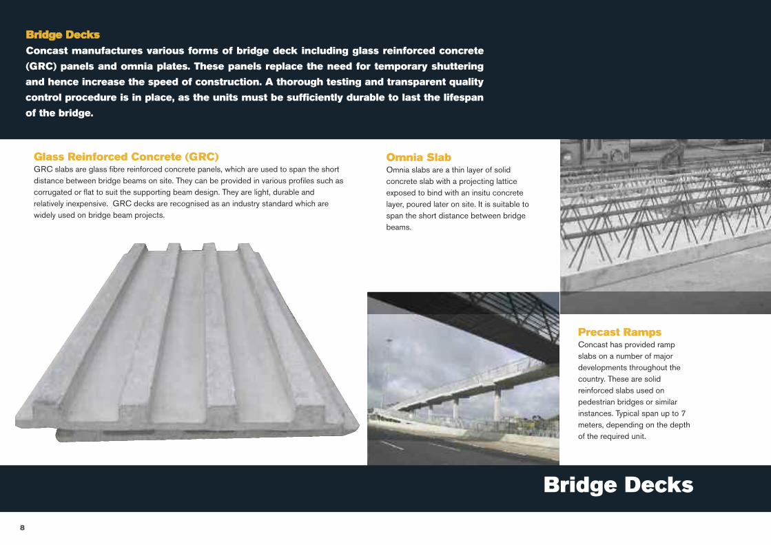
8
Bridge Decks
Glass Reinforced Concrete (GRC)GRC slabs are glass fibre reinforced concrete panels, which are used to span the shortdistance between bridge beams on site. They can be provided in various profiles such ascorrugated or flat to suit the supporting beam design. They are light, durable andrelatively inexpensive. GRC decks are recognised as an industry standard which arewidely used on bridge beam projects.
Omnia SlabOmnia slabs are a thin layer of solidconcrete slab with a projecting latticeexposed to bind with an insitu concretelayer, poured later on site. It is suitable tospan the short distance between bridgebeams.
Precast RampsConcast has provided rampslabs on a number of majordevelopments throughout thecountry. These are solidreinforced slabs used onpedestrian bridges or similarinstances. Typical span up to 7meters, depending on the depthof the required unit.
Bridge DecksConcast manufactures various forms of bridge deck including glass reinforced concrete
(GRC) panels and omnia plates. These panels replace the need for temporary shuttering
and hence increase the speed of construction. A thorough testing and transparent quality
control procedure is in place, as the units must be sufficiently durable to last the lifespan
of the bridge.
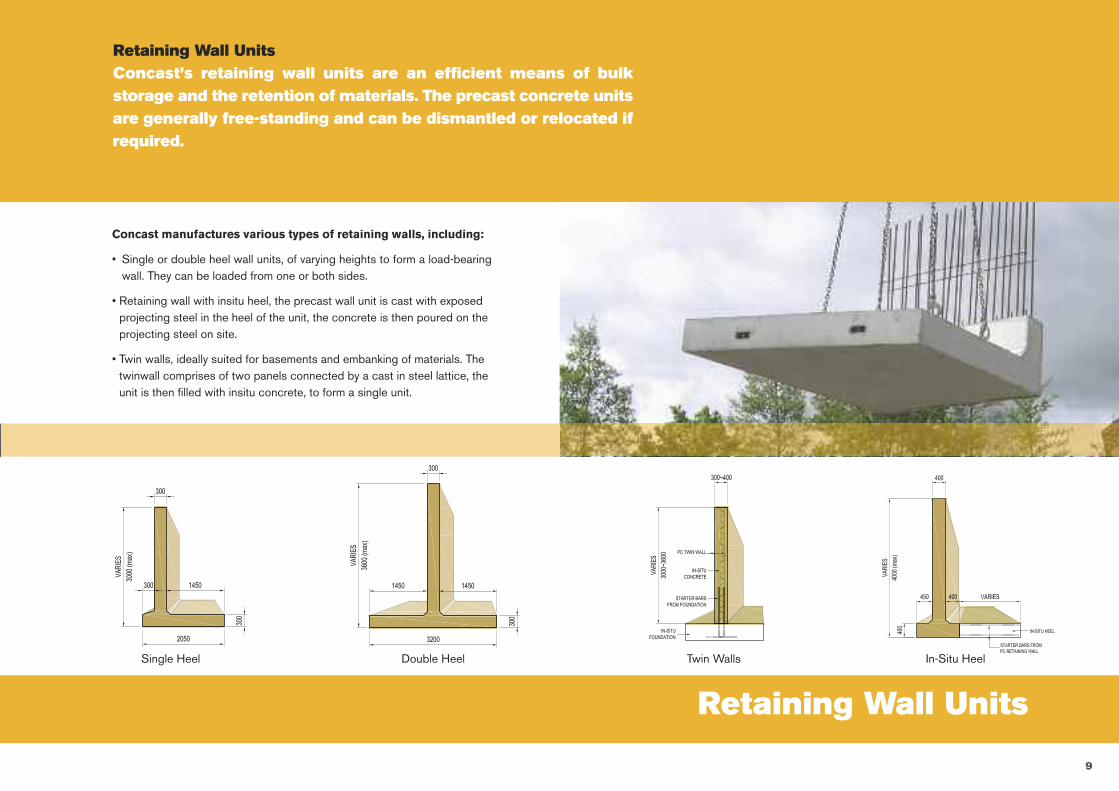
Retaining Wall Units
9
Retaining Wall UnitsConcast’s retaining wall units are an efficient means of bulkstorage and the retention of materials. The precast concrete unitsare generally free-standing and can be dismantled or relocated ifrequired.
Concast manufactures various types of retaining walls, including:
• Single or double heel wall units, of varying heights to form a load-bearingwall. They can be loaded from one or both sides.
• Retaining wall with insitu heel, the precast wall unit is cast with exposedprojecting steel in the heel of the unit, the concrete is then poured on theprojecting steel on site.
• Twin walls, ideally suited for basements and embanking of materials. Thetwinwall comprises of two panels connected by a cast in steel lattice, theunit is then filled with insitu concrete, to form a single unit.
Single Heel Double Heel Twin Walls In-Situ Heel
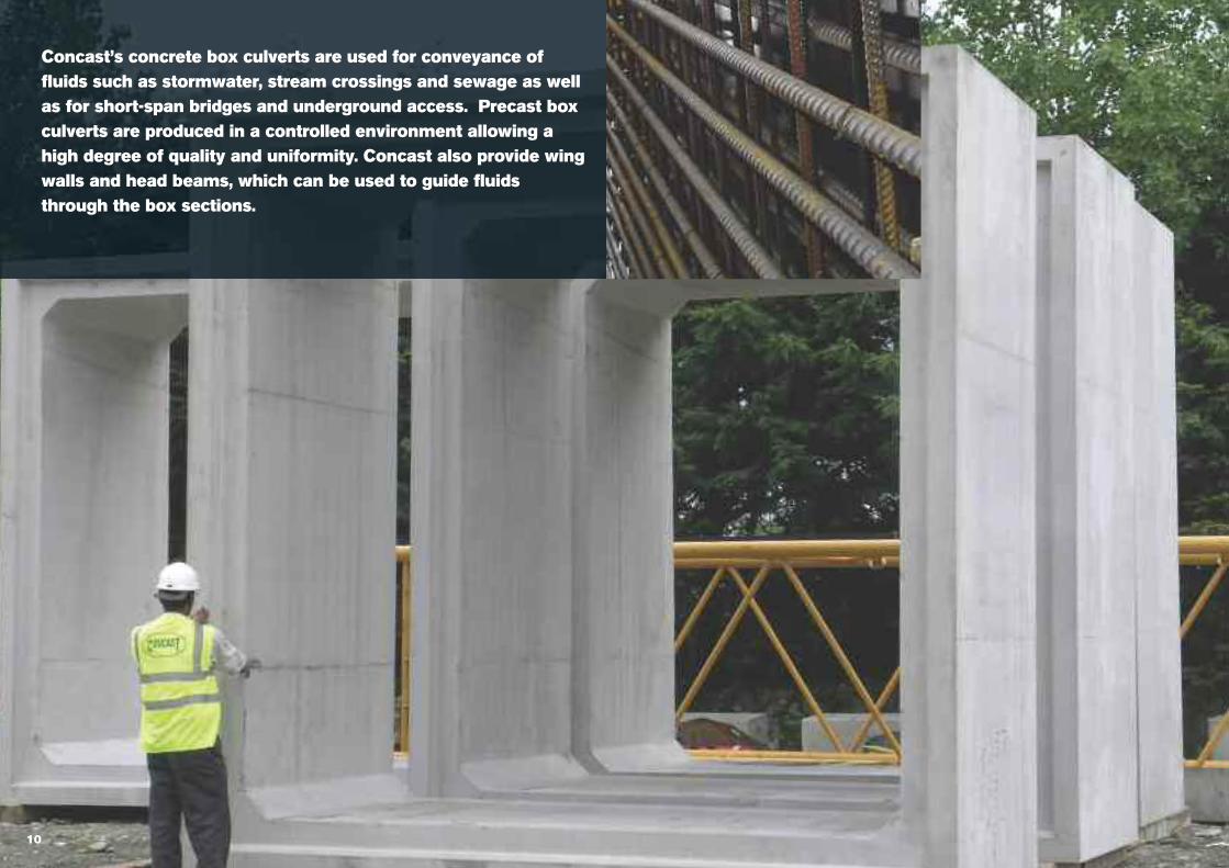
Concast’s concrete box culverts are used for conveyance offluids such as stormwater, stream crossings and sewage as wellas for short-span bridges and underground access. Precast boxculverts are produced in a controlled environment allowing ahigh degree of quality and uniformity. Concast also provide wingwalls and head beams, which can be used to guide fluidsthrough the box sections.
10
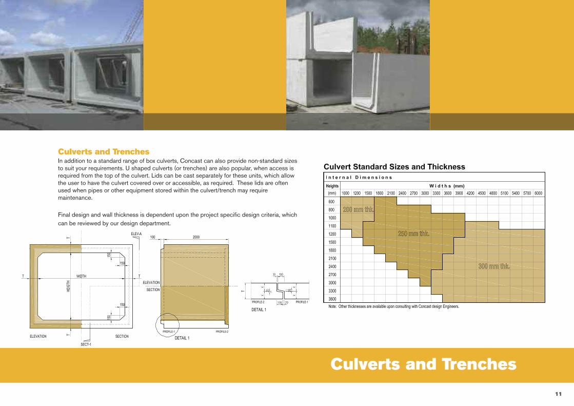
Culverts and Trenches
11
Culverts and TrenchesIn addition to a standard range of box culverts, Concast can also provide non-standard sizesto suit your requirements. U shaped culverts (or trenches) are also popular, when access isrequired from the top of the culvert. Lids can be cast separately for these units, which allowthe user to have the culvert covered over or accessible, as required. These lids are oftenused when pipes or other equipment stored within the culvert/trench may requiremaintenance.
Final design and wall thickness is dependent upon the project specific design criteria, whichcan be reviewed by our design department.
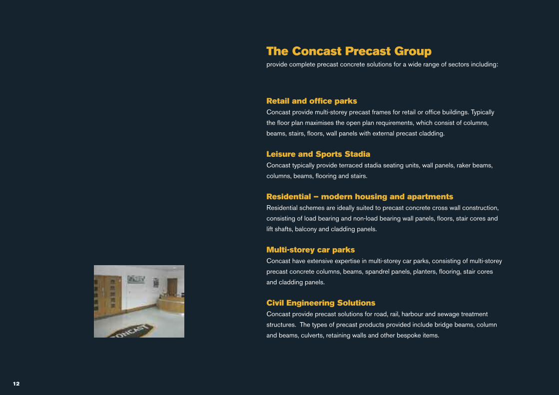
The Concast Precast Groupprovide complete precast concrete solutions for a wide range of sectors including:
Retail and office parksConcast provide multi-storey precast frames for retail or office buildings. Typically
the floor plan maximises the open plan requirements, which consist of columns,
beams, stairs, floors, wall panels with external precast cladding.
Leisure and Sports StadiaConcast typically provide terraced stadia seating units, wall panels, raker beams,
columns, beams, flooring and stairs.
Residential – modern housing and apartmentsResidential schemes are ideally suited to precast concrete cross wall construction,
consisting of load bearing and non-load bearing wall panels, floors, stair cores and
lift shafts, balcony and cladding panels.
Multi-storey car parksConcast have extensive expertise in multi-storey car parks, consisting of multi-storey
precast concrete columns, beams, spandrel panels, planters, flooring, stair cores
and cladding panels.
Civil Engineering SolutionsConcast provide precast solutions for road, rail, harbour and sewage treatment
structures. The types of precast products provided include bridge beams, column
and beams, culverts, retaining walls and other bespoke items.
12
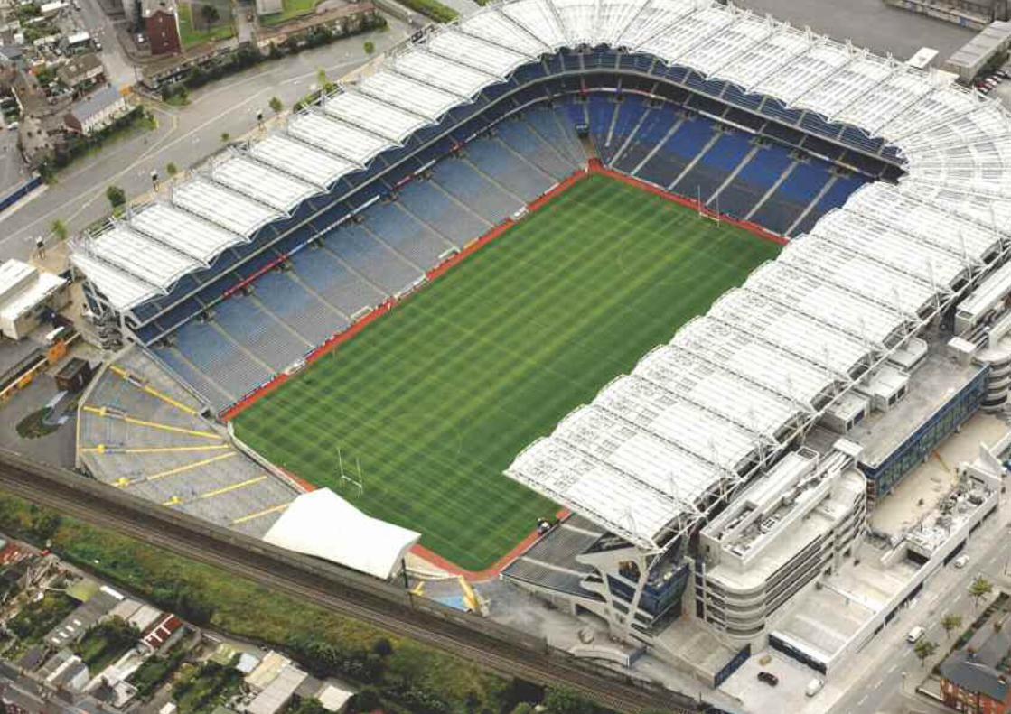
+ 44 (0)845 399 1592
+ 353 (0)1 628 8055
www.concast.ie
Registered Head-office:
Concast
Hazelhatch
Newcastle
Co. Dublin