Embed Size (px)
Citation preview

Manual
Precast Prestressed ConcreteParking Structures:
Recommended Practice for Design and Construction
MNL-129-15
Third Edit ion

Precast Prestressed Concrete
PARKING STRUCTURES:Recommended Practice for Design and Construction

Copyright 2015 The Precast/Prestressed Concrete Institute
All Rights Reserved
No part of this document may be copied or reproduced in any form or by any means without the prior written consent of
the Precast/Prestressed Concrete Institute.
Printed in the United States of America
ISBNPrint: 978-0-9797042-7-7ePub: 978-0-9797042-8-4
Substantial effort has been made to ensure that all data and information in this Recommended Practices manual are accurate. However, PCI cannot accept responsibility for any errors or oversights in the use of material or in the preparation of engineering plans. This publication is intended for use by professional personnel compe-tent to evaluate the significance and limitations of its contents and able to accept responsibility for the application
of the material it contains. Special conditions on a project may require more specific evaluation and practical engineering judgment.
MNL-129-15
On the cover: Cook County Juvenile Center Parking Garage, Chicago, ILPhoto: William Kildow Photography
200 West Adams Street #2100, Chicago, IL 60606Phone: (312) 786-0300 Fax: (312) 786-0353http://www.pci.org e-mail: [email protected]

James P. AndazolaDusty E. Andrews,
SecretaryDavid ChapinLarry ChurchSkip FrancisSuresh S. GamiHarry GleichMohammad S. HabibRobert Hyland
Farid IbrahimGerald KingWalter KorkoszMichael W. LeeJeffrey LepardWilliam Adrian Lovell Jr.Charles LoweCharles Magnesio,
TAC LiaisonFrank Nadeau
Todd M. NealPeter D. NeedhamRick OstgardRuss RandallJoey D. RowlandEdith SmithMaher K. TadrosWen S. TsauCarl WalkerDonald E. Whiteley
PCI COMMITTEE ON PARKING STRUCTURES
Ned Cleland, ChairmanJeffrey R. Carlson, Vice Chairman
Precast Prestressed Concrete
PARKING STRUCTURES:Recommended Practice for Design and Construction


Table of Contents
Parking Structures: Recommended Practice for Design and Construction 1-V
1.0 INTRODUCTION .......................................................................................................... 1-1
1.1 General .............................................................................................................1-1
1.2 Aesthetics ........................................................................................................ 1-2
1.3 Functional Design ............................................................................................ 1-3
1.4 Durability .......................................................................................................... 1-3
1.5 Sustainability ................................................................................................... 1-4
1.6 Structural Framing Systems ........................................................................... 1-5
1.7 Construction ..................................................................................................... 1-6
1.8 Maintenance .................................................................................................... 1-6
1.9 Research and Technical Support .................................................................... 1-7
2.0 PARKING STRUCTURE FUNCTIONAL DESIGN ............................................................. 2-1
2.1 Introduction ..................................................................................................... 2-1
2.2 Types of Parking Structures ............................................................................ 2-12.2.1 Operational Types .................................................................................. 2-1
2.2.2 Building Code Classification ................................................................. 2-2
2.2.3 Mixed-Use Parking Structures ............................................................... 2-4
2.3 Revenue Control/ Operating Systems ............................................................. 2-52.3.1 Transient or Hourly Parking .................................................................. 2-5
2.3.2 Monthly Contract Parking ..................................................................... 2-5
2.3.3 Cashiering .............................................................................................. 2-6
2.4 Street Access Design ....................................................................................... 2-72.4.1 Entrances ............................................................................................... 2-7
2.4.2 Exits ....................................................................................................... 2-9
2.5 Floor-to-Ceiling Clearance .............................................................................. 2-9
2.6 Circulation and Ramping ............................................................................... 2-10
2.7 Parking Configuration.................................................................................... 2-142.7.1 Level of Service ................................................................................... 2-15
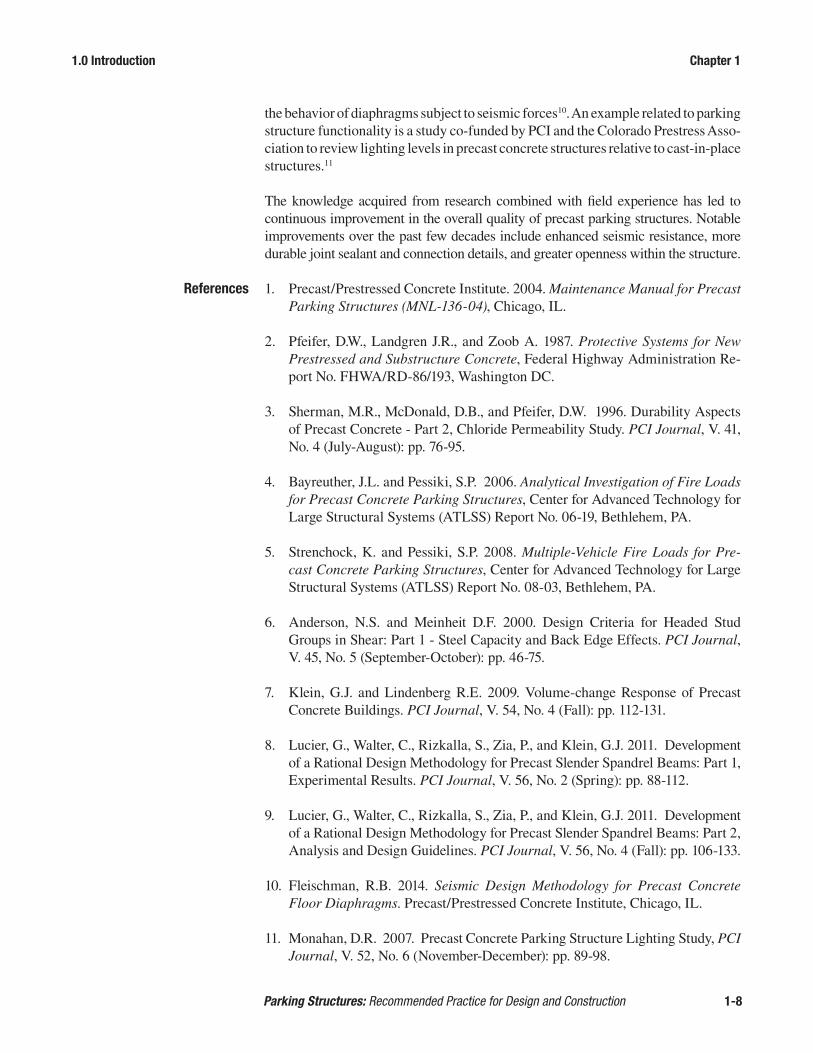
2.7.2 Parking Geometrics ............................................................................. 2-16
2.8 Accessible Parking ........................................................................................2-192.8.1 Accessible Space Layout and Identification ........................................ 2-19
2.8.2 Van Accessible Spaces ......................................................................... 2-20

Table of Contents
Parking Structures: Recommended Practice for Design and Construction 1-VI2-VI
2.9 Pedestrian Circulation .................................................................................. 2-21
2.10 Safety and Security ...................................................................................... 2-222.10.1 Passive Security ...................................................................................2-22
2.10.2 Active Security ....................................................................................2-23
2.11 Lighting ......................................................................................................... 2-232.11.1 Lighting Design Criteria ......................................................................2-24
2.11.2 Fixture Selection ..................................................................................2-25
2.11.3 Light Source Selection ........................................................................2-26
2.11.4 Fixture Placement ................................................................................2-27
2.11.5 Electrical Equipment Room ................................................................2-28
2.12 Wayfinding, Signage, and Graphics ............................................................. 2-292.12.1 Introduction .........................................................................................2-29
2.12.2 Wayfinding...........................................................................................2-29
2.12.3 Signage ................................................................................................2-29
2.12.4 Graphics ...............................................................................................2-32
2.12.5 Pavement Markings .............................................................................2-32
2.13 Other Items to Consider ................................................................................ 2-332.13.1 Fire Protection .....................................................................................2-33
2.13.2 Physical Hazards .................................................................................2-34
2.13.3 Vehicle Barriers and Pedestrian Guards ..............................................2-34
2.14 Sustainability ................................................................................................ 2-34
2.15 Summary ....................................................................................................... 2-35
3.0 DURABILITY CONSIDERATIONS ................................................................................ 3-1
3.1 Introduction .................................................................................................... 3-1
3.2 Durability Factors ........................................................................................... 3-1
3.3 The Deterioration Mechanisms ...................................................................... 3-6
3.4 Designing for Durability ................................................................................. 3-63.4.1 Concrete Quality ....................................................................................3-7
3.4.1.1 Deck Surfaces ......................................................................3-8
3.4.1.2 Finishing ..............................................................................3-9
3.4.1.3 Curing ..................................................................................3-9
3.4.2 Drainage ................................................................................................3-9
3.4.2.1 Drains ................................................................................3-11
3.4.3 Concrete Cover ....................................................................................3-11
3.4.4 Concrete Surface Sealers .....................................................................3-12
3.4.4.1 Penetrating Sealers ............................................................3-12

Table of Contents
Parking Structures: Recommended Practice for Design and Construction 1-VII2-VII
3.4.4.2 Non-penetrating Sealers ....................................................3-13
3.4.4.3 Geographic Considerations ...............................................3-13
3.4.5 Crack Prevention, Control Joints and Isolation Joints .........................3-13
3.4.5.1 Construction and Control Joints ........................................3-14
3.4.5.2 Isolation Joints ...................................................................3-14
3.4.6 Additional Durability Measures ..........................................................3-14
3.4.6.1 Epoxy-Coated Reinforcement ...........................................3-15
3.4.6.2 Traffic-Bearing Membranes ..............................................3-15
3.4.6.3 Corrosion Inhibitors ..........................................................3-16
3.4.6.4 High Performance Concrete ..............................................3-17
3.4.6.5 Protection for Precast Connections ...................................3-17
3.4.6.6 Precast Stair Units .............................................................3-17
3.4.6.7 Electrical Accessories ........................................................3-17
3.5 Joint Sealants ............................................................................................... 3-183.5.1 Joint Sealant Material Selection ..........................................................3-18
3.5.2 Joint Design .........................................................................................3-19
3.5.3 Surface Preparation .............................................................................3-20
3.5.3.1 Pretopped Systems ............................................................3-20
3.5.3.2 Field-topped systems .........................................................3-20
3.6 Joint Connections ......................................................................................... 3-203.6.1 Installation of Connectors....................................................................3-21
3.6.2 Welding of Connectors ........................................................................3-22
3.7 Maintenance Program .................................................................................. 3-23
3.8 Durability Considerations Summary ............................................................ 3-23
4.0 SUSTAINABILITY ....................................................................................................... 4-1
4.1 Principles ........................................................................................................ 4-14.1.1 Sustainable Parking Structures ..............................................................4-1
4.1.2 Strategies for Sustainable Parking Structures ........................................4-1
4.1.3 Precast Concrete Systems as Sustainable Products ...............................4-3
4.1.5 Definitions and Terminology .................................................................4-6
5.0 STRUCTURAL DESIGN ............................................................................................... 5-1
5.1 Introduction .................................................................................................... 5-1
5.2 Gravity and Vehicle Impact Loads .................................................................. 5-15.2.1 Dead Loads ............................................................................................5-1
5.2.2 Live Loads .............................................................................................5-2
5.2.2.1 Uniform Load ......................................................................5-2

Table of Contents
Parking Structures: Recommended Practice for Design and Construction 1-VIII2-VIII
5.2.2.2 Concentrated Load ..............................................................5-2
5.2.2.3 Load on Vehicle Barrier Systems ........................................5-2
5.2.2.4 Special Vehicle Loading ......................................................5-3
5.2.2.5 Snow Load ...........................................................................5-3
5.3 Lateral Loads .................................................................................................. 5-45.3.1 Seismic Forces .......................................................................................5-4
5.3.2 Wind Loads ............................................................................................5-5
5.3.3 Earth Pressure ........................................................................................5-5
5.4 Volume Changes ............................................................................................. 5-65.4.1 Shrinkage and Creep..............................................................................5-7
5.4.2 Temperature-Related Volume Changes .................................................5-8
5.4.3 Volume Change Effects on the Structural System ................................5-9
5.4.4 Expansion Joints ..................................................................................5-10
5.4.4.1 Framing at Expansion Joints .............................................5-12
5.4.4.2 Expansion Joint Details .....................................................5-13
5.5 Considerations for Fire ................................................................................. 5-15
5.6 Structural Components ................................................................................ 5-165.6.1 Stemmed Floor Members ....................................................................5-16
5.6.2 Hollow Core and Flat Slabs .................................................................5-22
5.6.3 Composite Topping for Stemmed and Slab Floor Members ...............5-22
5.6.4 Beams and Spandrels ...........................................................................5-22
5.6.5 Columns ...............................................................................................5-24
5.6.6 Wall Panels ..........................................................................................5-24
5.6.7 Stair/Elevator Cores .............................................................................5-24
5.7 Lateral Force-Resisting Systems ................................................................. 5-255.7.1 Floor Diaphragms ................................................................................5-25
5.7.2 Shear Walls ..........................................................................................5-26
5.7.3 Moment Resisting Frames ...................................................................5-26
5.7.4 Ramp Truss Action ..............................................................................5-27
6.0 CONNECTIONS........................................................................................................... 6-1
6.1 General ............................................................................................................ 6-1
6.2 Continuity of Load Path .................................................................................. 6-1
6.3 Ductility ........................................................................................................... 6-2
6.4 Gravity Connections ........................................................................................ 6-2
6.5 Lateral System Connections ........................................................................... 6-3
6.6 Seismic Design Considerations ...................................................................... 6-4

Table of Contents
Parking Structures: Recommended Practice for Design and Construction 1-IX2-IX
6.7 Structural Integrity Connections ..................................................................... 6-4
6.8 Fabrication and Erection Considerations ....................................................... 6-6
6.9 Connection Materials ....................................................................................... 6-6
6.10 Galvanizing-Special Precautions ................................................................... 6-7
6.11 Expansion Joint Details ................................................................................... 6-7
6.12 Common Example Connection Details ............................................................ 6-7
7.0 PRODUCTION .............................................................................................................. 7-1
7.1 Concrete Quality .............................................................................................. 7-17.1.1 Admixtures ............................................................................................ 7-1
7.2 Casting Standardization .................................................................................. 7-27.2.1 Products ................................................................................................. 7-2
7.2.1.1 Double Tees ......................................................................... 7-2
7.2.1.2 Beams .................................................................................. 7-3
7.2.1.3 Spandrels & Walls ............................................................... 7-3
7.2.1.4 Columns .............................................................................. 7-4
7.2.2 Daps, Blockouts and Haunches ............................................................. 7-4
7.3 Non-Prestressed Reinforcing .......................................................................... 7-5
7.4 Cast-In Materials ............................................................................................. 7-57.4.1 Standardization ...................................................................................... 7-6
7.4.2 Inserts .................................................................................................... 7-6
7.4.3 Sleeves ................................................................................................... 7-6
7.4.4 Plate Assembly Anchorages .................................................................. 7-6
7.5 Molds/Formwork ............................................................................................. 7-7
7.6 Product, Interfacing and Erection Tolerances ............................................... 7-77.6.1 Product Tolerances ................................................................................ 7-7
7.6.1.1 Structural Conditions ........................................................... 7-8
7.6.1.2 Connection Tolerances ........................................................ 7-8
7.6.1.3 Visual Effects ...................................................................... 7-8
7.6.2 Interfacing Tolerances ........................................................................... 7-9
7.6.2.1 Door and Window Blockouts .............................................. 7-9
7.7 Quality Control ................................................................................................. 7-97.7.1 Inspections by the Precaster .................................................................. 7-9
7.7.1.1 Pre-Pour Inspection ............................................................. 7-9
7.7.1.2 Post-Pour Inspection ........................................................... 7-9
7.7.1.3 Miscellaneous Inspections ................................................... 7-9
7.7.2 Observations by the Structural Engineer of Record (SER) ................... 7-9

Table of Contents
Parking Structures: Recommended Practice for Design and Construction 1-X2-X
7.8 Finishes ......................................................................................................... 7-107.8.1 Floor Member Finishes........................................................................7-10
7.8.2 Exposed Surface Finishes ....................................................................7-10
7.8.3 Architectural Finishes ..........................................................................7-10
7.8.4 Facade Samples ...................................................................................7-10
7.9 Production Summary .................................................................................... 7-11
8.0 ERECTION CONSIDERATIONS .................................................................................... 8-1
8.1 Introduction .................................................................................................... 8-1
8.2 Erection Considerations During Design ......................................................... 8-2
8.3 Preconstruction Planning ............................................................................... 8-38.3.1 Erection Plan .........................................................................................8-5
8.3.1.1 Additional Considerations ...................................................8-6
8.4 Transportation and Unloading ........................................................................ 8-6
8.5 Rigging ............................................................................................................ 8-7
8.6 Stability ........................................................................................................... 8-7
8.7 Field Considerations for Connections ............................................................ 8-88.7.1 General Considerations .........................................................................8-8
8.7.2 Temporary Connections .........................................................................8-8
8.7.3 Types of Connections ............................................................................8-9
8.7.3.1 Bolted Connections .............................................................8-9
8.7.3.2 Welded Connections ............................................................8-9
8.7.3.3 Grout, Mortar and Drypack ...............................................8-10
8.8 Installation .................................................................................................... 8-118.8.1 General ................................................................................................8-11
8.8.2 Loadbearing Members .........................................................................8-11
8.8.2.1 Columns ............................................................................8-11
8.8.2.2 Beams and Spandrels ........................................................8-13
8.8.2.3 Wall Panels ........................................................................8-13
8.8.3 Floor Members ....................................................................................8-15
8.8.3.1 Double Tees .......................................................................8-15
8.9 Erection Tolerances ...................................................................................... 8-168.9.1 General ................................................................................................8-16
8.9.2 Connection Tolerances ........................................................................8-17
8.9.3 Hardware .............................................................................................8-17

Table of Contents
Parking Structures: Recommended Practice for Design and Construction 1-XI
8.10 Post-Installation Considerations .................................................................. 8-178.10.1 Protection of Work ...............................................................................8-17
8.10.2 Repairs at the Jobsite ...........................................................................8-18
8.10.3 Cleaning ...............................................................................................8-19
8.10.4 Acceptance ..........................................................................................8-19
8.11 Conclusion .................................................................................................... 8-19

Table of Contents
Parking Structures: Recommended Practice for Design and Construction 1-XII

1.0 Introduction Chapter 1
Parking Structures: Recommended Practice for Design and Construction 1-1
1.0 INTRODUCTION 1.1 General Parking structures are essential components of the built environment. These struc-
tures have evolved from utilitarian, non-descript, box-like structures to multi-pur-pose, architecturally pleasing buildings that complement the facility served. Own-ers have realized that accommodations for parking often represent the first and last impression that the public experiences. The quality of parking can be a pivotal fac-tor in determining the level of customer, resident, guest, or employee satisfaction. Surface parking is often remote, undesirable, or not possible, resulting in a need for multi-level parking. In such instances, creating an attractive, functional, and durable parking structure is a critical objective of the design and construction program.
Precast, prestressed concrete has inherent characteris-tics that can make it the optimum structural material and framing system for parking structures. The intent of this manual is to describe features that make it a desirable choice and to serve as a guide for architects, engineers, contractors, and owners involved in the de-sign, construction, and maintenance of parking struc-tures.
This manual consists of eight chapters. Chapter 1 pro-vides an overview of the content of the manual and highlights many of the beneficial features of precast, prestressed concrete. Chapter 1 also includes photo-graphs that illustrate the flexibility and architectural design possibilities available with precast, prestressed concrete. Chapters 2, 3, and 4 contain general infor-mation relating to functional design, durability, and sustainability. Chapters 5 through 8 discuss matters
relating to structural design, production, and erection. These four chapters provide more in-depth technical information intended primarily for designers, producers, and contractors.
Information, details, and diagrams presented herein are intended as general ref-erence material only. In no case should the material presented be considered as a substitute for the experience and engineering judgment of a design professional or producer.
Project specific criteria or regional practices should be considered and may result in alternative design approaches or solutions. PCI-certified producers are expected to produce a higher quality product than a producer that is not certified. Consult-
Figure 1-1. Surf Style Retail Store and Parking Structure - Tampa, FL (photo courtesy of Finfrock Industries)

1.0 Introduction Chapter 1
Parking Structures: Recommended Practice for Design and Construction 1-2
ing with a regional PCI-certified producer during conceptual design can provide significant benefits with respect to achieving a functional, architecturally pleasing structure that can be constructed in a cost-effective and timely manner.
1.2 Aesthetics Since the 1980s, pre-
cast concrete parking structures have been incorporating in-creased sophistication in the use of architec-tural materials as own-ers and architects have recognized the bene-fits associated with an aesthetically pleasing structure. Figures 1-1 through 1-12 show photographs of pre-cast parking structures that have successfully incorporated a variety of materials and treatments. Facade finishes commonly utilized include exposed aggregate, decorative patterns, thin masonry and tile. Precast facing products may cover large surfaces or serve only as accent bands. Sandblasting and chemical re-tarders are common methods of enhancing the appearance of the aggregate and tex-ture of the finished precast concrete component. Differences in color can be readily achieved by use of pigments added to the concrete mix, use of white cements, or selection of special aggregate blends. Alternatively, paint and other decorative coat-ings can be applied to create a wide range of appearances.
The overall mass of the parking structure can be propor-tioned and detailed to allow the facility to blend in with the surrounding environment. The structure can project a bold, contemporary style if the adjacent facilities feature modern architectural style. Alternately, the structure can express a historic or traditional look if needed to blend in with nearby structures. Long, horizontal openings above spandrels commonly associated with parking structures can be interrupted with vertical elements to create small-er framed openings mimicking an office building or other structure having a more intricate facade. The possibilities for architecturally pleasing facade treatments are only limited by the imagination of the designer.
Figure 1-2. The Z - Detroit, MI (photo: Neumann/Smith Architecture)
Figure 1-3. Shops at Willow Bend Parking Deck A – Plano, TX

1.0 Introduction Chapter 1
Parking Structures: Recommended Practice for Design and Construction 1-3
1.3 Functional Design A good functional design for a parking structure is essential for acceptance by the
user. Elements of functional design should consider the user type, interaction of vehicles and pedestrians, maneuverability, and wayfinding. Other considerations include safety, security, traffic flow, lighting, and location of stairs and elevators.
Open spaces within the structure, readily accessible communication stations, ample lighting, clear signage, and good housekeeping are among the factors that project a comfortable atmosphere to the user. Other factors which help to achieve a function-al design include efficient access and exiting, effective revenue control, and good ventilation. Roofs can be designed as landscaped areas, plazas, recreation, or other non-parking functions to serve the needs of residents or users of adjacent buildings. The street level could be designed for mixed uses including retail and office space.
1.4 Durability Precast concrete parking structures are inherently durable. Durability begins with
use of high performance concrete and is enhanced with the application of prestress-ing to mitigate cracking. The ability of concrete to resist high compressive stress combined with the ability of prestressing steel to withstand high tensile stresses results in the ideal combination of structural materials.
Precast concrete products are manufactured under plant-controlled conditions, re-ducing many of the variations in materials and workmanship inherent with cast-in-place concrete. All aspects of concrete placement, finishing, and curing can be closely controlled in a plant environment. For producers having in-plant batching capability, all aspects of concrete mixture and delivery can also be closely con-trolled. As a result, optimum combinations of materials and curing conditions can be achieved on a consistent basis. Using best practices, the resulting precast con-crete product can be expected to be of a very high quality.
For example, concrete with very low water-cementitious material (w/cm) ratio is easily produced and placed in plant conditions. Concrete mixes with very low w/cm ratios (less than 0.40) have low permeability and, therefore, high resistance to undesirable ingress of moisture and chlorides. Also, curing can easily be acceler-
Figure 1-4. Publix GreenWise - Tampa, FL (photo credit Nino Giannotti)

1.0 Introduction Chapter 1
Parking Structures: Recommended Practice for Design and Construction 1-4
ated in a plant to facil-itate development of early age strength and other desirable con-crete properties.
The primary structur-al reinforcing steel in double tees is typical-ly located in the lower portion of the stem, a significant distance away from ingress of moisture, chlorides, and other contam-inants. Reinforcing steel placement in plant conditions is better controlled than field-placed reinforcing steel, resulting in a low likelihood of insufficient concrete cover. These factors provide additional means of improving the durability of precast concrete products. Combined with proper drainage, connections that accommodate volume change, and a regular maintenance program, precast, prestressed concrete parking structures can be expected to remain in service for half a century or more.
1.5 Sustainability Sustainable design
should have the ulti-mate goal of a “net-ze-ro” structure or a struc-ture that will have no negative impact on our environment nor future generations that will use the earth. While this goal may not be easy to accomplish, the design of “green” structures is currently realistic and PCI has developed publications to identify the many goals and design ap-proaches. As it relates to parking structures, precast concrete components possess a number of characteristics that can aid more sustainable designs. These features include durability, resiliency, use of local ma-terials, optimization of materials by use of prestressing, and minimal consumption of formwork. In addition, concrete mixtures can incorporate recycled products and industrial combustion wastes (e.g., fly ash or silica fume), and reinforcement made from recycled steel can be used.
Figure 1-5. San Jose International Airport Parking Structure - San Jose, CA (photo: Mikki Piper)
Figure 1-6. Hartford Hospital Hudson Street Employee Parking Garage - Hartford, CT (photo courtesy of Halkin Mason Photography)

1.0 Introduction Chapter 1
Parking Structures: Recommended Practice for Design and Construction 1-5
As use of public trans-portation to reduce our consumption of ener-gy resources becomes encouraged, a parking structure may appear to serve as a disincen-tive to reducing auto-mobile use and con-verting to mass transit. However, most users of mass transit arrive at bus or rail stations in private vehicles, so parking structures are often required to serve those users, espe-cially for transit facilities located on a small site. Although the aggregate number of parking spaces in a dense urban core may be slightly reduced as use of public transportation becomes more prevalent, parking structures will continue to be an essential component of the overall built environment. Therefore, designers, con-tractors, and owners should commit to creating and managing parking structures in a manner that makes optimum use of our resources while also mitigating overall detrimental effects on the environment. Examples of design features that are con-sistent with this philosophy include preferred parking spaces for high-efficiency vehicles, provisions for bicycle storage, energy management systems for lighting control, and solar panels above the top parking level.
1.6 Structural Framing Systems Because precast con-
crete deck components can effectively span long distances, good visibility and effective vehicular circulation is readily achieved within precast concrete park-ing structures. Double tee spans of 60 to 65 feet are common. This span range allows for column-free bays with space for parking stalls on both sides of drive aisles (Figure 1-11). Wind loads and seismic forces are transferred through the floor diaphragms to the vertical components of the lateral force-resisting systems. Shear walls are the most common vertical components of the lateral force-resisting system. These walls can incorporate openings to improve visibility and user safety within the structure (Fig-ure 1-12). When functional considerations do not allow use of shear walls, moment resisting frames, either as H frames or jointed frames, represent a viable alternative depending on height of the structure and other factors.
Figure 1-7. Lancaster Newspapers Parking Garage – Lancaster, PA
Figure 1-8. Halifax International Airport Parking Garage - Enfield, NS, Canada (photo courtesy of NORR Limited)

1.0 Introduction Chapter 1
Parking Structures: Recommended Practice for Design and Construction 1-6
1.7 Construction Precast concrete park-
ing structures offer a number of construction advantages relative to other structural sys-tems because of de-sign and construction efficiencies. Exam-ples include optimum use of materials (e.g., high performance con-crete and high tensile strength prestressing steel), ease of incorporating architectural features, minimal on-site labor, and minimal on-site staging.
Perhaps no advantage is greater than the potential for a significant reduction in construction schedule, relative to use of other structural systems. Precast con-crete parking structures can be erected immediately after the foundation has been constructed because the production of precast concrete components takes place simultaneously with construction at the project site. Because precast con-crete components are fabricated in plant conditions, production is typically not affected by inclement weather, a con-gested or unprepared jobsite, or other common scheduling impediments.
The construction cost and schedule ad-vantages associated with precast con-
crete parking structures translates into better use of the site for other trades, and alternative use of the owner’s budget for other components of the overall construc-tion program. For facilities that have a pressing need for parking to accommodate customers or the public, the shorter construction schedule allows the parking struc-ture to be placed in service sooner than structures constructed using other framing systems.
1.8 Maintenance Like all other buildings, parking structures require attention and maintenance to
maximize their service lives. The PCI Maintenance Manual for Precast Parking Structures1 describes procedures that are essential to achieving long-term durability. Maintenance programs are critical for extending the service life of a parking struc-ture and proper maintenance can contribute to reducing the life cycle cost of the facility. The exposure of parking structures to adverse environments (e.g., extreme temperatures, snow, ice, and deicing salts) and dynamic concentrated loads from ve-
Figure 1-9. Reynolds Street Parking Deck - Augusta, GA (photo: George Spence courtesy of Metromont)
Figure 1-10. Yankee Stadium 161st Parking Garage C - New York, NY (photo courtesy of Jeffery Totaro Photography)

1.0 Introduction Chapter 1
Parking Structures: Recommended Practice for Design and Construction 1-7
hicles can result in deg-radation of even well designed and construct-ed facilities.
An effective mainte-nance program includes a timetable and task list customized to the type of facility. Writ-ten documentation of maintenance activities should be preserved to help plan future activ-ities and develop reli-able operating budgets. These tasks combined with appropriate inspections and repairs will ensure that the structure remains in optimum condition throughout its life. The types of materials used, the structural system employed, and other design and construction features are significant factors in developing a maintenance program. Therefore, the owner’s maintenance expec-tations should be established at the onset of the design phase.
1.9 Research and Technical Support The beneficial features of precast concrete have been well established by the work
of researchers over many decades. Studies performed by public and private orga-nizations, universities, and other institutions have shown consistently that precast concrete materials and systems have superior characteristics which make it the de-sired choice for parking structures.
For example, the durability benefit of using low water-ce-mentitious (w/cm) ratio concrete mixtures discussed in Section 1.4 is based on research by the Federal Highway Administration.2 Similar research by Wiss, Janney, Elst-ner Associates, Inc. confirmed the use of w/cm ratio as a reliable predictor of durability.3 Research by The Center for Advanced Technology for Large Structural Systems (ATLSS) to assess the effects of fires in a typical precast parking structure showed only a minimal reduction in prestressing steel strength when the structure is exposed to a single-vehicle fire.4, 5
PCI’s commitment to supporting development of state-of-the-art technical information is evidenced by its funding of research efforts on matters of interest to designers, pro-ducers, and other stakeholders in the precast industry. Ex-amples related to design of precast concrete components
include studies to assess the strength of headed stud anchors6, to evaluate the effect of volume change7, to understand the behavior of spandrel beams 8, 9, and to understand
Figure 1-11. Typical interior view of precast concrete structure showing long, clear spans
Figure 1-12. Typical view of openings in shear walls
1.0 Introduction Chapter 1
Parking Structures: Recommended Practice for Design and Construction 1-8
the behavior of diaphragms subject to seismic forces10. An example related to parking structure functionality is a study co-funded by PCI and the Colorado Prestress Asso-ciation to review lighting levels in precast concrete structures relative to cast-in-place structures.11
The knowledge acquired from research combined with field experience has led to continuous improvement in the overall quality of precast parking structures. Notable improvements over the past few decades include enhanced seismic resistance, more durable joint sealant and connection details, and greater openness within the structure.
References 1. Precast/Prestressed Concrete Institute. 2004. Maintenance Manual for Precast Parking Structures (MNL-136-04), Chicago, IL.
2. Pfeifer, D.W., Landgren J.R., and Zoob A. 1987. Protective Systems for New Prestressed and Substructure Concrete, Federal Highway Administration Re-port No. FHWA/RD-86/193, Washington DC.
3. Sherman, M.R., McDonald, D.B., and Pfeifer, D.W. 1996. Durability Aspects of Precast Concrete - Part 2, Chloride Permeability Study. PCI Journal, V. 41, No. 4 (July-August): pp. 76-95.
4. Bayreuther, J.L. and Pessiki, S.P. 2006. Analytical Investigation of Fire Loads for Precast Concrete Parking Structures, Center for Advanced Technology for Large Structural Systems (ATLSS) Report No. 06-19, Bethlehem, PA.
5. Strenchock, K. and Pessiki, S.P. 2008. Multiple-Vehicle Fire Loads for Pre-cast Concrete Parking Structures, Center for Advanced Technology for Large Structural Systems (ATLSS) Report No. 08-03, Bethlehem, PA.
6. Anderson, N.S. and Meinheit D.F. 2000. Design Criteria for Headed Stud Groups in Shear: Part 1 - Steel Capacity and Back Edge Effects. PCI Journal, V. 45, No. 5 (September-October): pp. 46-75.
7. Klein, G.J. and Lindenberg R.E. 2009. Volume-change Response of Precast Concrete Buildings. PCI Journal, V. 54, No. 4 (Fall): pp. 112-131.
8. Lucier, G., Walter, C., Rizkalla, S., Zia, P., and Klein, G.J. 2011. Development of a Rational Design Methodology for Precast Slender Spandrel Beams: Part 1, Experimental Results. PCI Journal, V. 56, No. 2 (Spring): pp. 88-112.
9. Lucier, G., Walter, C., Rizkalla, S., Zia, P., and Klein, G.J. 2011. Development of a Rational Design Methodology for Precast Slender Spandrel Beams: Part 2, Analysis and Design Guidelines. PCI Journal, V. 56, No. 4 (Fall): pp. 106-133.
10. Fleischman, R.B. 2014. Seismic Design Methodology for Precast Concrete Floor Diaphragms. Precast/Prestressed Concrete Institute, Chicago, IL.
11. Monahan, D.R. 2007. Precast Concrete Parking Structure Lighting Study, PCI Journal, V. 52, No. 6 (November-December): pp. 89-98.

2.0 Parking Structure Functional Design Chapter 2
Parking Structures: Recommended Practice for Design and Construction 2-1
2.0 PARKING STRUCTURE FUNCTIONAL DESIGN
2.1 Introduction Parking structures are unique transportation facilities for vehicle travel, vehicle
storage and pedestrian travel, particularly since the personal interchange between vehicles and pedestrians occurs in a relatively confined environment. Because this is unique, the design specialty of parking consulting has evolved. For completeness of detail and quality completion of a project, it is important that the project owner or developer retain a qualified parking consultant.
This chapter provides an overview of many of the non-structural aspects of the de-sign of multilevel parking structures. Functional design involves the development of vehicle and pedestrian flow in a parking structure as well as the parking space layout. Operating and security functions are also considered in functional design.
Specific functional design considerations for efficient design include:
• level of service• parking structure type• revenue control/operating systems• street access design • circulation and ramping • parking configuration• pedestrian circulation • safety and security • lighting• graphics & signage• fire protection, ventilation, and other issues
2.2 Types of Parking Structures
2.2.1 Operational Types The two general types of parking operations are valet/attendant-park and self-park.
In valet/attendant-park facilities, vehicles are left at the entrance by the driver and a valet attendant then parks the vehicle. When the driver returns, the attendant re-trieves the vehicle and transfers it to the driver at the exit. Valet/attendant-park fa-cilities typically seek to maximize the utilization of the parking structure footprint by using tandem/stacked parking (Figure 2-1). This type of operation is often used

2.0 Parking Structure Functional Design Chapter 2
Parking Structures: Recommended Practice for Design and Construction 2-2
where a high level of customer service is desired such as fine dining restaurants, hospitals, offices, hotels, boutique retail shops, special events, and at many airports.
The most common type of parking structure in North America is the self-park facil-ity where drivers park and retrieve their own vehicle (Figure 2-2). This chapter will discuss only the self-park approach to functional design.
2.2.2 Building Code Classification The International Building Code (IBC)1 categorizes typical parking structures as
Occupancy Type S-2 – Low Hazard Storage. Special requirements for motor vehi-cle occupancy are defined in the IBC and are divided in two categories: open park-ing garages and enclosed parking garages. An open parking garage has sufficient clear openings in exterior walls to allow the natural ventilation of smoke and vehicle emissions to the outside. Parking garages that do not meet the code requirements for an open parking garage are considered enclosed. Enclosed parking garages are subject to more stringent code requirements as discussed later in this section.
The code prescribes that an open parking garage must have uniformly distributed openings on a minimum of two sides over 40% of the building perimeter at each level. The area of such openings on each level must be at least 20% of the total perimeter wall area at each level. In addition, any interior walls shall be at least 20% open with uniformly distributed openings. When meeting the open parking garage classification, mechanical ventilation and fire suppressions systems are not required. Also, an open parking garage classification carries more favorable code treatment, such as open stairs, non-rated shaft enclosures, longer exit distances, more favorable height and area limitations, etc. Whenever possible, the designer is encouraged to proportion the perimeter of the parking structure such that an open parking garage classification is achieved.
Parking garages are designed as either Type I or Type II construction. The differ-ence between the two construction types and sub-types is the fire-resistance rating required. Type 1A requires a 3 hour rating of the bearing walls and primary struc-tural frame and a 2 hour rating for the floors. Type 1B requires a 2 hour rating for
Standard Parking Module Standard Parking Module
Figure 2-1 Tandem Parking Layout Figure 2-2 Self Park Layout

2.0 Parking Structure Functional Design Chapter 2
Parking Structures: Recommended Practice for Design and Construction 2-3
frame and floors. Type IIA requires a one hour rating for frame, walls and floors, and Type IIB only requires that the framing be non-combustible.
The most important consideration for precast concrete is the fire rating required for the floors. In general, two fire endpoints must be considered to determine fire resistances. The structural endpoint requires the floor to have the capacity to carry load for the duration of the fire rating, which can be a challenge for some stem thicknesses and strand arrangements used in double tees. The heat transmission endpoint considers temperature on the top of the floor opposite the fire. For double tees, flange thickness will have to increase over standard flange thickness as fire rating requirements increase beyond one hour. In IBC 2015, the heat transmission requirement has been waived for both open and enclosed parking structures. It is still favorable if the fire rating requirements can be limited to one hour or non-com-bustible, Type IIA or Type IIB.
The code prescribes the limitations of each construction type based on the height in tiers and the area of the typical floor. The height and area limitations for open parking garages are more favorable than standard buildings or enclosed garages. With Type IA and Type IB construction, the floor area is unlimited. The height is unlimited for Type IA and limited to 12 tiers for Type IB. For Type IIA and Type IIB, the floor area is limited to 50,000 square feet and the building height limitation is 10 tiers and 8 tiers, respectively. That does not, however, mean that Type IIA or Type IIB parking structures cannot be built any larger. There are provisions which allow for height and area increases if additional conditions are met.
If perimeter openings exceed the minimum for open parking garages, the limits on height and area can be increased for Type IIA and Type IIB construction. For garages with sides open on three-fourths of the building perimeter, it is permitted to increase the area by 25% and the height by one tier. When the sides are open all around the perimeter, the area may be increased by 50%. For these provisions, however, the measurement of openness changes from that used for the basic de-termination of an open parking garage. For a side to be considered open, the total openings along the side cannot be less than 50% of the “interior area,” as opposed to the “exterior wall area.” For this calculation, the height need not be taken greater than 7 ft. That means, for example, that a garage with 11 foot floor-to-floor height with 7 foot deep spandrel beams and 4 foot tall openings may comply with 50% openness if the area obstructed by columns and walls is less than the 50% of the perimeter length.
When a Type II garage is open on all sides and the height is less than 75 feet, the area is unlimited as long as no locations are greater than 200 feet from an exterior opening. If the 200 foot requirement cannot be met, an interior court not less than 20 feet wide may be provided.
In a separate provision, the area limit for a garage that has fewer tiers than permit-ted may be increased when at least three sides of each larger tier has a horizontal opening not less than 30 inches in height for at least 80% of the length of the sides and no part of the larger tier is more than 200 feet from an exterior opening. For this increase, the openings must face a street or yard with accessible space at least

2.0 Parking Structure Functional Design Chapter 2
Parking Structures: Recommended Practice for Design and Construction 2-4
30 feet in width. In this case, the increase is permitted such that the total area of all the tiers is not more than the total permitted for the higher structure.
These provisions for height and area increases provide many options for larger Type II garages with the economy of lower fire rating requirements. Parking struc-tures classified as enclosed parking garages will require mechanical ventilation and a fire-suppression sprinkler system. Also, the stair towers and other vertical enclo-sures are required to be enclosed and rated. Due to the higher life safety hazards, enclosed garages are subject to more restrictive heights and floor areas, although height and area increases are permitted because of the sprinkler system requirement.
When part of a garage must be constructed below grade with not more than one sto-ry above grade, it can be classified as a separate building and the parking above can be classified as open parking structure. In this case, the floor construction between the two classifications must be rated as required for the lower enclosed garage.
2.2.3 Mixed-Use Parking Structures Parking structures are often included within mixed-use developments or integrated
into high density urban areas. In these cases, other uses such as mercantile, resi-dential, or business are included adjacent to or within the parking structure. Such mixed-use parking facilities are a growing trend that requires a careful review of applicable building codes.
Mixed use parking structures typically feature ground level lease space with park-ing below, above, or adjacent to the secondary use. The IBC allows this arrange-ment of uses by requiring appropriate fire rated separation above, below, and ad-jacent to the parking areas. In most cases, it is possible to obtain an open parking structure classification and avoid fire suppression systems if certain conditions are met. A close review of the building code and discussion with local building officials is recommended.
Central core or “wrapped” parking structures have become common in high density residential communities. Typically, these facilities are stand-alone parking struc-tures surrounded on two or more sides with residential units. The parking is con-veniently centered in the development and is partially or completely hidden from exterior view. The parking levels are generally aligned with the perimeter floors, allowing direct access to the residential corridors. In many cases, the surrounding building shares a common wall with the parking structure creating an enclosed garage. However, by providing an appropriate physical separation, it is possible to obtain an open parking garage classification.
In the case where a parking structure and an adjacent building share a common wall, the classification of the wall should be carefully considered. In most cases, the wall can be designed to meet the requirements of a “fire barrier” wall. This type of wall carries only the fire-resistance rating requirements typical of occupancy separations. When the wall is defined as a “fire wall” or “party wall”, the construc-tion must be designed such that, under fire conditions, the building on one side of the wall may be allowed to collapse while the other side remains stable. This may involve construction of two walls instead of one to comply with this requirement.

2.0 Parking Structure Functional Design Chapter 2
Parking Structures: Recommended Practice for Design and Construction 2-5
The IBC code commentary discusses instances where fire walls may be required.
Whether enclosed or open, the code treatment of wrapped parking structures must be approached very carefully since local building officials sometimes find it diffi-cult to understand the life safety risks associated with this particular arrangement of buildings.
2.3 Revenue Control/ Operating Systems Not all parking facilities require access and revenue controls. When needed, self-
park facilities generally have two access control locations, one at the entrances and the other at the exits. These control locations typically serve two types of parkers: the hourly or daily transient parker and the monthly contract parker. They may also serve parkers attending special events or those having certain reserved parking privileges.
2.3.1 Transient or Hourly Parking At the entrance, the transient or hourly parker normally takes a time-encoded tick-
et from a ticket dispenser, the entry control gate opens, and the parker enters the facility and drives to an available parking space. Sometimes two ticket dispensers are installed on the same lane to prevent lane shutdown in case a ticket dispenser malfunctions. To exit, the parker retrieves the vehicle and drives to an exit where the time-encoded ticket is given to a cashier. The information is entered into a fee computer which determines the parking fee. Once the transaction is completed, the exit control gate opens, and the parker leaves the facility and enters the street sys-tem. Section 2.3.3 discusses the various types of non-cashier payment machines.
There are also various types of ungated systems that can adequately serve transient and hourly parkers. Ungated systems rely on equipment such as honor boxes, park-ing meters, pay and display machines, pay-by-space or multi-space meters, and timed permits. Each of these systems relies on various forms of enforcement to ensure collection of parking fees.
2.3.2 Monthly Contract Parking The most common method of handling monthly parkers in North America is with a
key card system. A magnetic or radio-frequency identification (RFID) card, similar to the size of a credit card, is read by the card receiver at the entrance. The electron-ic system validates the key card and activates the entry control gate, thus allowing the parker to enter the facility. Monthly contract parkers may be directed to use the same entrance as the hourly parker (Figure 2-3), or a different entrance (Figure 2-4). Depending on the traffic circulation pattern, the monthly contract parker may use the same parking spaces as the hourly parker or may be directed to a sepa-rate monthly contract parking area. When exiting the facility, the monthly contract parker uses the RFID card to activate the exit gate.

2.0 Parking Structure Functional Design Chapter 2
Parking Structures: Recommended Practice for Design and Construction 2-6
A newer technology, Automatic Vehicle Identification (AVI) is becoming a popular alternative to the key card system. With an AVI system, the user’s car is equipped with an electronic transponder affixed to the inside of the windshield. The transpon-der transmits a signal to a reader device positioned near the entrance. The reader validates the signal and electronically opens the gate to allow access to the parking area. Similarly, the AVI reader opens the gate to allow the user to exit. AVI systems offer several advantages over conventional RFID card systems such as increased throughput rates, convenience to the user, and ease of collecting fees through com-puterized systems tied to the transponders.
Computerized access control systems use an anti-passback feature that requires the key card to be used at an exit before it is again valid at an entry gate. This feature prevents the reuse of a key card by another driver if the original user has entered the facility and not yet exited. Also, computerized systems may use computer inputs to lock-in or lock-out a vehicle if the monthly contract parker has not paid the required parking fee.
One method to reserve the more-convenient lower floor parking spaces for hourly parkers is to restrict these spaces from use by monthly parkers in the early morning hours, when the majority of them arrive (Figure 2-5). In some cases, a second set of access control equipment is provided at a specif-ic area in the interior of the facility. Specific users have access to this segregated area thus ensuring that this user group parks in their dedicated space.
2.3.3 Cashiering Revenue control is one of the major objectives of parking operating equipment. Au-
tomatic-read and semi-automatic cashiering systems are commonly used to reduce revenue pilferage and revenue loss by cashier error.
Cashiering operations for transient or hourly parking may be accomplished in sev-eral ways. The most common is the exit cashiering in which the parking fee is cal-culated and received by the cashier at the pay booth (Figure 2-6). Another method
Figure 2-5
Loop Detector
Gate
TicketDispenser
Monthlyand Hourly
Parking
AVI Readeror
Key CardReceiver
Loop Detector
Gate
TicketDispenser
MonthlyContractParking
HourlyParking
AVI Readeror
Key CardReceiver
Figure 2-3 Figure 2-4

2.0 Parking Structure Functional Design Chapter 2
Parking Structures: Recommended Practice for Design and Construction 2-7
of exit lane cashiering is by using a “pay-in-lane” machine. These devices function by receiving the user’s ticket and calculating the required fee. The user inserts the proper fee using cash or credit card. Upon receipt of the fee, the device sends a signal to the gate to open.
Pre-cashiering is a system in which the parker pays an attendant in a central loca-tion after returning to the parking structure but before retrieving the vehicle. The parker is then given an exit pass with a grace period, usually 15-20 minutes, in which the parker can retrieve the vehicle and exit the facility. The exit pass then is read by a ticket receiver at the exit to open the exit gate.
This method may be further automated by using a “pay-on-foot” pre-cashiering system (Figure 2-7) which is quite popular in Europe and becoming common place in North America. This system uses either a magnetic stripe or bar code ticket is-sued by a ticket dispenser at the entrance. Prior to retrieving their vehicle, the park-er inserts the ticket in an automatic cashiering machine that computes the fee. The parker then inserts cash or credit card into the machine and receives an exit ticket. This ticket is then used when leaving the facility to activate the exit gate.
In addition to outbound cashiering and pre-cashiering, inbound cashiering often is used in structures serving event facilities such as convention centers and entertain-ment/sports arenas. Inbound cashiering usually is done on a flat parking fee basis (even dollar amount) and, once the event is over, traffic free-flows outbound.
2.4 Street Access Design The external street traffic configuration can have a major impact on how a parking
structure is used. This section discusses the inter-relationship of vehicle entrances and exits with the surrounding street system.
2.4.1 Entrances Generally, entrances are placed on the high-volume streets providing direct access
from the parker’s origin to the parking destination. It is often advantageous for parking facilities to have more than one entrance. This provides convenient access for parkers from various adjacent streets and offers an additional entrance in case operating equipment malfunctions. Entrances should also be spaced away from street intersections (Figure 2-8).
Figure 2-6 Figure 2-7

2.0 Parking Structure Functional Design Chapter 2
Parking Structures: Recommended Practice for Design and Construction 2-8
Vehicle entrances should be visible and easily identifiable. The minimum distance of an entry from corner intersections is at least 100 ft but preferably 150 ft. Entranc-es should have clear lines-of-sight. It is preferable to enter a facility from a one-way street or by turning right from a two-way street. Entry areas that have parking con-trol equipment should be kept relatively flat. Ideally, these areas should not have a slope gradient greater than 3%.
Where a parking facility is adjacent to a high-volume or high-velocity street, a deceleration lane prior to the entrance helps eliminate accidents and street traffic slowdown (Figure 2-9). Entrance ticket dispensers and gates preferably should be set in from the street far enough so that, when a car is at the ticket dispenser or key-card reader, another car can enter behind the first car and be clear of the sidewalk (Figure 2-10). A vehicle with a driver taking a ticket from a dispenser must be clear of the adjacent sidewalks and curb lines. When designing the entrances, a large van should be used as the “design vehicle” to check turning movements and dimen-sional clearances. Some jurisdictions now require justification for queuing distance based on flow calculations.
It is very important to provide the appropriate number of entry lanes to meet pro-jected peak traffic volumes. The number of lanes is a function of user groups served, peak-hour traffic volumes, and service rates of the parking control equipment. One inbound lane can handle a peak entry volume of 450 vehicles per hour with an auto-mated ticket dispenser and up to 600 vehicles per hour with a proximity card reader. For higher traffic volumes additional entry lanes will be required. A lane and queu-ing analysis study should be conducted to ensure sufficient entry and exit capacity.
Operators often will monitor entrances remotely from the cashier and manager’s office area with closed circuit television (CCTV) cameras. The CCTV camera, cou-pled with an audio intercom installed in the ticket dispensers or card readers aid communication if there is an equipment malfunction or if a parker has a question when entering the facility.
The architectural design of entrances impacts a successful parking operation. The entrances should be designed to be obvious and to look different from exits. Spe-cial architectural features such as arches, canopies, marquees, and other elements attract attention to the entrance and are encouraged (Figures 2-11 and 2-12).
Parking Structure
Two Way
One
Way
One
Way
Parking Structure
Parking DecelerationLane
ThroughTraf�cLanes
AVI Readeror
Key CardReceiver
TicketDispenser
Desi
rabl
e M
inim
um
Dist
ance
= 4
0'
Figure 2-8 Figure 2-9 Figure 2-10

2.0 Parking Structure Functional Design Chapter 2
Parking Structures: Recommended Practice for Design and Construction 2-9
2.4.2 Exits Exits should be placed on low-volume streets, if possible, to reduce exiting delays
caused by street congestion. Warning signals are recommended where exiting vehi-cles cross pedestrian traffic ways.
As with entrances, exits should be located at least 100 ft from a street intersection. Right turns upon exiting are preferred for best traffic flow with high volume. The peak exit volume should be considered in determining the appropriate number of exit lanes. It is preferable to have all exiting cashier booths grouped together so the parking structure can operate with one cashier during low-volume periods, mini-mizing operating costs. Alternately, internal traffic flow should allow circulation past a closed secondary exit to access the primary exit during off-peak hours.
The number of cashiering, key-card, and AVI exit lanes will vary depending on the facili-ty size and ratio of monthly contract parkers to transient parkers. Also, a turn into an exit lane can slow down the exiting rate of flow. For a typical municipal combination transient/monthly parking facility, one cashier lane for each 300 spaces should be adequate. For most parking facilities, at least two exit lanes are recommended. One lane is used as a primary cashiering lane, and the second lane is used as a secondary or peak-load cashiering lane. The secondary lane, however, is always available for monthly key-card and AVI exiting, allowing the monthly parker to bypass any backup that occurs at the cashier booth. Exit lanes are typically configured to provide queuing space for at least one vehicle between the cashier booth and the adjacent street sys-tem or sidewalk (Figure 2-13).
2.5 Floor-to-Ceiling Clearance The IBC requires a minimum ceiling clearance of 7'-0" in typical floor areas and 8'-
2" for ADA van clearance. Since these are code minimum clearances, the designer and precast manufacturer must include an allowance for tolerances to ensure code minimums are maintained. Often the clearance to the underside of beams and dou-
Figure 2-13
Queu
e20
' Min
.
AVI ReaderorKey CardReceiver
CashierBooth
Gate
Figure 2-11 Figure 2-12

2.0 Parking Structure Functional Design Chapter 2
Parking Structures: Recommended Practice for Design and Construction 2-10
ble tee stems is increased to 7'-2" or more to provide a greater feeling of spacious-ness, to provide better readability of overhead signs, and to allow for additional tolerance. The depth of the structural system is typically in the range of 3'-0" to 3'-6". Thus, typical floor-to-floor heights should be set at 10'-2" or greater to meet or exceed the minimum code requirements.
The Americans with Disabilities Act (ADA) requires an overhead clearance of 8'-2" for accessible spaces designated as “van accessible.” This clearance must be provided along the path of travel from the entrance to the van accessible space and back to the exit. All van accessible spaces may be located on the ground level so that only that level is required to have the additional clearance. Floor-to-floor heights on levels with ADA vans should be set at 11'-4" or greater to provide the required clearance. If a drop-off zone is located within the parking facility, the overhead clearance must be 9'-6". Local and state regulations may require greater clearance than the Federal ADA standards.
2.6 Circulation and Ramping One of the key components in the layout of a parking structure is the consideration
of circulation systems. A circulation system is the arrangement of parking bays and ramps that guide the driver from level to level and throughout the parking structure. This section will introduce commonly used ramping configurations and discuss their functionality.
Choosing a circulation system involves consideration of several factors. The first factor to consider will be the geometry and topography of the site. The site geome-try will dictate the maximum footprint available and thus the potential length of the structure and number of parking bays. The topography will likely give an indication of the best fit for the location and direction of the ramp or ramps.
Another important consideration is the type of user. If the parking facility serves repeat users of an office building for example, the circulation system can be more complex since the users will be familiar with the functionality. For a hospital or a shopping mall with infrequent users, the circulation system should be as simple as practical to avoid user confusion.
Finally, the height and number of spaces will need to be considered. A taller parking structure may need a more sophisticated ramping system to ease the loading and un-loading of the facility at peak times. Similarly, a very large parking structure will need a high capacity circulation system to effectively move vehicles through the facility.
Another factor in choosing a circulation system is the consideration of 90-degree parking with two-way traffic versus angled parking with one-way traffic (Figure 2-14). In many cases, 90-degree parking is more efficient and practical for simple two-bay parking facilities. Advantages of angled parking include the ease of enter-ing a parking space, a narrower bay module, and the elimination of two-way traffic conflicts and possible congestion. While 90-degree parking could be used in a park-ing bay with one-way traffic, it does not reinforce the one-way traffic direction that angled parking creates.

2.0 Parking Structure Functional Design Chapter 2
Parking Structures: Recommended Practice for Design and Construction 2-11
The most common circulation system used in free-standing parking structures in North America is the continuous ramp, where sloping floors with aisles and park-ing off both sides of the aisle offer access to the parking spaces and the circulation route. If the parking structure is of sufficient length such that one ramped bay can be reasonably sloped to rise the full floor to floor height , the other bay may be left flat (Figure 2-15). Whether there are two sloped bays or one sloped bay and one flat bay, this type of circulation is called a “single thread helix.”
Because the single thread helix rises only one level for every 360 degree revolution through the structure, the number of levels (floors) should preferably be limited to a maximum of seven. With more levels, the number of turns required and the number of spaces passed becomes inconvenient. A structure with a two-bay single thread design has a maximum capacity of approximately 750 spaces for a low-turn-over facility, such as an office building. For a high-turnover facility such as a shop-ping mall, the maximum capacity for a two-bay single thread should be limited to 400-spaces.
Some advantages of a Single-thread Helix design include:
• Repetitive and easy to understand for users.• Potentially more flat-floor parking and level façade elements.• Better visibility across the structure, which enhances security.
Principal disadvantages of a Single-thread Helix:
• More revolutions required going from bottom to top and top to bottom.• Two-way traffic bays have less flow capacity than one-way traffic bays. Traffic
in both directions is impeded by vehicles parking and un-parking.
The continuous ramp circulation system can be configured in a variety of ways including the two-bay end-to-end (Figure 2-16), the double-thread helix (Figure 2-17), the three-bay double-thread (Figure 2-18), and the four-bay side-by-side (Figure 2-19). All of these circulation patterns lend themselves to one-way traffic and angled parking, although two-way traffic and 90 degree parking may also be accommodated.
A double-thread helix can work with either one-way or two-way traffic flow, al-though one-way traffic is more common. A double-thread helix configuration al-lows the driver to ascend two levels in height with every 360 degrees of revolution.
Two Way One WayAi
sle
Mod
ule
Mod
ule
Aisl
e
Figure 2-14

2.0 Parking Structure Functional Design Chapter 2
Parking Structures: Recommended Practice for Design and Construction 2-12
This allows for two intertwined “threads” and the opportunity to circulate to an available parking space without passing all parking spaces as up bound and down bound traffic are separated. Because of this, a double-thread helix is often recom-mended for larger facilities with seven or more levels. A two-bay double thread helix has a functional system capacity of approximately 1,500 spaces with 90 de-gree parking and two-way traffic when used as a low turnover facility. For angled parking and one-way traffic, the capacity is lower at approximately 1,350 spaces. For high turnover facilities such as shopping malls, the capacities are somewhat lower at 800-900 spaces depending on the parking angle.
Some advantages of a Double-thread Helix include:
• Efficient circulation and greater traffic flow capacity• Pass fewer spaces both inbound and outbound.
Principal disadvantages of a Double-thread Helix:
• Can be complex and confusing, particularly in finding one’s vehicle upon return to the parking facility.
Figure 2-18 Figure 2-19 Figure 2-20
Figure 2-21
Figure 2-15 Figure 2-16 Figure 2-17
Two BayTwo Way Single Thread Helix
Three BayOne Way Double Thread Helix
Express Ramp
Two BayOne Way End to End Single Helix
Four BayOne Way Side By Side Single Helix
Two BayOne Way Double Thread Helix
Two BayTwo Way Split Level Helix

2.0 Parking Structure Functional Design Chapter 2
Parking Structures: Recommended Practice for Design and Construction 2-13
• Two-sloped bays and minimal flat-floor parking.• Typically need to cross over at the midpoint of the ramp and yield to enter down
bound circulation.• Site must be long enough to accommodate ramps that can rise one story height
with a reasonable slope.
Two other circulation systems are the split-level layout as shown in Figure 2-20 and the flat plate with express ramp as shown in Figure 2-21. The two-bay split-level lay-out is typically used on very small footprints or when flat floor parking is desired. The parking levels are offset by half a story height and con-nection between floors is accomplished with a short and relatively steep ramp. The in-ter-level ramp can tend to be uncomfortable for drivers to negotiate, but may be appropriate for low-turnover facilities such as for residential or office building uses.
The flat plate with ex-press ramp is often used in retail situations where sloping floors are pro-hibited because of the potential for run-away shopping carts. The ramp may be positioned either inside or outside the deck footprint and can ascend one or more levels.
Large-capacity parking structures, serving airports, stadiums, entertainment parks, etc., often use flat parking levels with spiral helix ramps for circulation (Figure 2-22). These structures often use electronic counting systems and variable message displays to show the parking availability on different parking floors. This helps di-rect the user to the level with the most available spaces and removes the need to search the entire parking facility for an available space. Sloped, straight ramps are also used as entering and exiting express ramps (Figure 2-23). In cold weather areas
Figure 2-22
Figure 2-23

2.0 Parking Structure Functional Design Chapter 2
Parking Structures: Recommended Practice for Design and Construction 2-14
where ice and snow events occur frequently, express ramps often have snow-melt systems to help improve safety.
Typical grades in continuous ramp facilities on the parking floors generally do not exceed 6%. However, ramp grades up to 6.67% are allowed by the IBC. Speed ramps (non-parking) should be limited to a 12% grade unless pedestrians specifi-cally are excluded from the ramp by signage. Ramp grades greater than 16% can be psychological barriers to some drivers, particularly when the ramp is down-bound. If ramps are used as a means of egress, the slope shall not exceed 8%.
When the ramp’s break over slope exceeds 10%, a vertical-curve transition or a transition slope of half the prevailing ramp slope should be used (Figure 2-24). This will prevent the bottom of the vehicle from scraping the floor surface. Height clear-ances on ramp breaks should be checked from the wheel line, not from the floor surface (Figure 2-25).
2.7 Parking Configuration One of the major advantages of using precast, pre-
stressed concrete to construct a parking structure is its ability to provide economical clear span parking bays. Clear spans provide a number of user and operational benefits. First, columns are eliminated between parking spaces, thus promoting the ease of entering the parking space without the “fender bender” stigma and provid-ing a more open line of sight. Second, the columns take space used for parking in a clear-span structure. Third, the clear span allows for future restriping of the park-ing spaces.
The advantages of being able to restripe in a clear span facility can be seen easily in light of historical chang-es in car size. The average new car in North America reduced considerably from 1975 to 1985 due to gaso-line efficiency laws. In 1975, a common parking space width and module was 9'-0" x 62'-0". By 1985, small-er cars were prevalent resulting in an acceptable space width and module of 8'-6" x 60'-0". In the 1990’s, sport utility vehicles and mid-sized sedans grew dramatically
> 10%Slope
> 10%Slope10' 0"
10' 0"
True Vehicle Clearance
Floo
r to
Ceili
ng H
t.
Figure 2-24 Figure 2-25
61' 0"
60' 0"
62' 0"
1975
1985
2005
8' 9
"8'
6"
9' 0
"
Figure 2-26

2.0 Parking Structure Functional Design Chapter 2
Parking Structures: Recommended Practice for Design and Construction 2-15
in popularity creating the need for larger spaces and modules. Today, space widths vary from 8'-6" to 9'-0" and typically 90-degree parking modules range from 60'-0" to 62'-0". Historical trends in parking layout are shown in Figure 2-26.
Some designers attempt to space columns along the bumper walls at a multiple of the parking space width so columns projecting into the structure do not interfere with parking. In other words, if a typical parking space is 8'-6" wide, columns would be spaced at 17'-0", 25'-6" or 34'-0". Since car lengths vary greatly and cars park randomly, column projections seldom cause problems. Typically, it is more economical to space columns on multiples of a double-tee module, which could be 10 ft, 12 ft or 15 ft de-pending on product availability in the area of the project. Column grids of 30'-0", 36'-0", 40'-0", 45'-0", and 48'-0" are common in precast parking structures.
Perhaps the most important design-related factor directly affecting construction costs is parking efficiency. Park-ing Efficiency is defined as the gross square feet of con-structed area per parking space. An efficiency rating of 320 square feet per space is commonly considered to be a very good design. The appropriate design efficiency is achieved primarily through the experience and creativity of the functional designer. However, a higher rating may result despite the best efforts of the functional designer due to limitations of the floor plate size, necessity of speed ramps, or local ordinances which dictate ineffi-cient parking module sizes. Also, consideration of the user may result in a higher efficiency rating. For a high-turnover parking structure serving a shopping mall, an efficiency of 320 to 340 square feet per car would be appropriate. For a low-turn-over facility serving an office building, an efficiency of 290 to 310 square foot per car would be acceptable.
The most efficient parking structure in terms of square feet per space is generally thought to be 90-degree parking with two-way traffic. However, the efficiency ad-vantage may be overstated. Properly designed angle-parking layouts with one-way end crossovers can yield similar efficiencies as compared to 90-degree layouts (Fig-ure 2-27). The ease of parking and improved safety with a one-way traffic angled parking layout may offset any decrease in efficiency when compared to 90-degree parking.
2.7.1 Level of Service Parking facility designers often use the Level-of-Service (LOS) approach to classify
the elements of the functional design that are of concern to the user. Some factors affecting the level- of- service include parking-space angle and width, drive-aisle width, number and radii of turns, ceiling heights, lighting levels, ramp slopes, pe-destrian crossings, entry/exit location and design, revenue control systems, vehicle travel distances, and the traffic circulation system. The level-of-service for parking structures may be described as follows:
26' 0"
16' 0"
Figure 2-27

2.0 Parking Structure Functional Design Chapter 2
Parking Structures: Recommended Practice for Design and Construction 2-16
LOS A = ExcellentLOS B = GoodLOS C = Average LOS D = Tolerable
LOS criteria should be related to the needs and concerns of users. Generally, users with low familiarity and high turnover should be accorded a higher LOS. For ex-ample, LOS A or B may be appropriate for high to moderate turnover parking such as a shopping mall or hospital. LOS C would be more appropriate for low turnover parking such as employee, commuter, resident, etc. LOS D is generally reserved for dense urban areas where land values and parking rates are at a premium.
2.7.2 Parking Geometrics Parking-space width and parking module (bumper wall to bumper wall dimension)
vary based on the desired level of service. Some parking structure designers pro-vide separate sizes of spaces for large and small cars, while most designers use one size for all parking spaces. It is not uncommon to see a “one-size-fits-all” parking space of 8'-6" (Figure 2-28) in width compared to a large car space of 9'-0" (Figure 2-29) wide and a small car space of 7'-6" wide (Figure 2-30). In the past, there was a greater difference between large cars and small cars. Over time, “small cars” have increased in size while “large cars” have decreased, resulting in a clustering of pas-senger vehicles around a 16 ft aggregate length. Therefore, the “one-size-fits-all” design approach is preferred over the distinct large and small car stalls.
Even with the “one-size-fits-all” concept, it is common to place small-car-only (SCO) spaces at the end of parking rows adjacent to turns. This helps ensure that a large vehicle does not project into the drive lane. To help control the size of vehi-cles using SCO spaces, a closure line is placed across the end of the space with a notation on the “small car only” sign of “Don’t overhang rear line” (Figure 2-30). When used extensively, small car spaces should not exceed 15% to 20% of the total capacity of a facility or as otherwise stipulated by local ordinances.
Vehicle turnover in a parking space is a factor in selecting parking space width. A low turnover facility for all-day parkers may have an 8'-6" width; 8'-9" may be provided for an average turnover and 9'-0" for a high turnover rate. A high turnover rate may be defined as more than five times per day per stall. For a mixed use facil-ity with different turnover rates, an average stall width based on user types may be acceptable.

2.0 Parking Structure Functional Design Chapter 2
Parking Structures: Recommended Practice for Design and Construction 2-17
Recommended parking geometrics for all levels of service are shown in Table 2-1. Dimensional efficiencies can be achieved with angled parking by interlocking the spaces as shown in the legend thus reducing the module width. It should be noted that the most critical dimensions in functional design are the stall and module width. The module width is somewhat dependent on the space width as a wider stall with a narrower module can achieve the same LOS as a narrower space with a wider module. A parking module can be decreased by 3 in. for every 1 in. increase in stall width and maintain the same LOS. It is acceptable to utilize different LOS for var-ious components of the design. For example, the parking module may be designed for a LOS C which would be 59'-6" but the space width may be a LOS A or 9'-0". The resulting geometry provides a LOS equivalent to an 8'-9" wide space and 60'-3" parking module which is nearly LOS B as indicated in Table 2-1. It is particularly useful to adjust space widths and module widths based on site geometry and park-ing efficiency while maintaining the desired LOS.
Figure 2-28 Figure 2-29 Figure 2-30
9" 9"
8' 6"
“One-Size-Fits-All”
17' 0
" 9" 9"
9' 0"
17' 0
"
Large Car Space Small Car Space
AddClosureStripe
16' 0
"
7' 6"
9" 9"
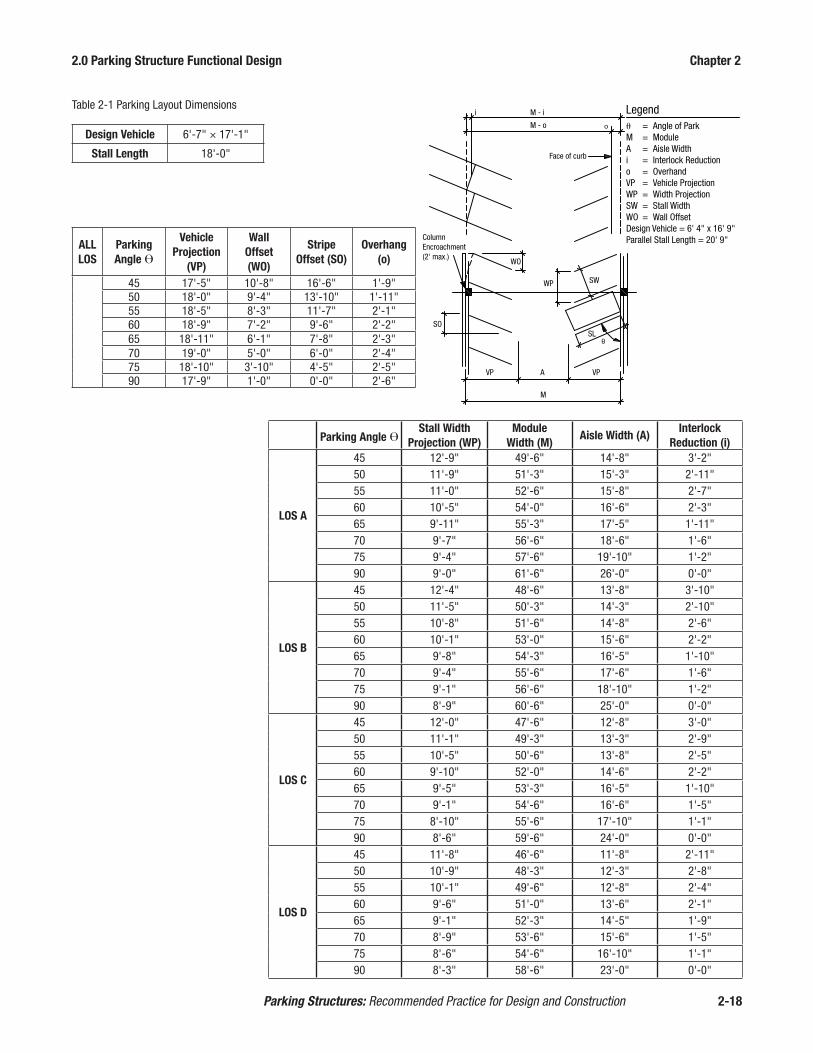
2.0 Parking Structure Functional Design Chapter 2
Parking Structures: Recommended Practice for Design and Construction 2-18
Parking Angle ϴStall Width
Projection (WP)Module
Width (M)Aisle Width (A)
Interlock Reduction (i)
LOS A
45 12'-9" 49'-6" 14'-8" 3'-2"50 11'-9" 51'-3" 15'-3" 2'-11"55 11'-0" 52'-6" 15'-8" 2'-7"60 10'-5" 54'-0" 16'-6" 2'-3"65 9'-11" 55'-3" 17'-5" 1'-11"70 9'-7" 56'-6" 18'-6" 1'-6"75 9'-4" 57'-6" 19'-10" 1'-2"90 9'-0" 61'-6" 26'-0" 0'-0"
LOS B
45 12'-4" 48'-6" 13'-8" 3'-10"50 11'-5" 50'-3" 14'-3" 2'-10"55 10'-8" 51'-6" 14'-8" 2'-6"60 10'-1" 53'-0" 15'-6" 2'-2"65 9'-8" 54'-3" 16'-5" 1'-10"70 9'-4" 55'-6" 17'-6" 1'-6"75 9'-1" 56'-6" 18'-10" 1'-2"90 8'-9" 60'-6" 25'-0" 0'-0"
LOS C
45 12'-0" 47'-6" 12'-8" 3'-0"50 11'-1" 49'-3" 13'-3" 2'-9"55 10'-5" 50'-6" 13'-8" 2'-5"60 9'-10" 52'-0" 14'-6" 2'-2"65 9'-5" 53'-3" 16'-5" 1'-10"70 9'-1" 54'-6" 16'-6" 1'-5"75 8'-10" 55'-6" 17'-10" 1'-1"90 8'-6" 59'-6" 24'-0" 0'-0"
LOS D
45 11'-8" 46'-6" 11'-8" 2'-11"50 10'-9" 48'-3" 12'-3" 2'-8"55 10'-1" 49'-6" 12'-8" 2'-4"60 9'-6" 51'-0" 13'-6" 2'-1"65 9'-1" 52'-3" 14'-5" 1'-9"70 8'-9" 53'-6" 15'-6" 1'-5"75 8'-6" 54'-6" 16'-10" 1'-1"90 8'-3" 58'-6" 23'-0" 0'-0"
ALL LOS
Parking Angle ϴ
Vehicle Projection
(VP)
Wall Offset (WO)
Stripe Offset (SO)
Overhang (o)
45 17'-5" 10'-8" 16'-6" 1'-9"50 18'-0" 9'-4" 13'-10" 1'-11"55 18'-5" 8'-3" 11'-7" 2'-1"60 18'-9" 7'-2" 9'-6" 2'-2"65 18'-11" 6'-1" 7'-8" 2'-3"70 19'-0" 5'-0" 6'-0" 2'-4"75 18'-10" 3'-10" 4'-5" 2'-5"90 17'-9" 1'-0" 0'-0" 2'-6"
Design Vehicle 6'-7" × 17'-1"
Stall Length 18'-0"
Table 2-1 Parking Layout Dimensions Legendθ = Angle of ParkM = ModuleA = Aisle Widthi = Interlock Reductiono = OverhandVP = Vehicle ProjectionWP = Width ProjectionSW = Stall WidthWO = Wall OffsetDesign Vehicle = 6' 4" x 16' 9"Parallel Stall Length = 20' 9"
M - ii
M - o
Face of curb
ColumnEncroachment(2' max.)
SO
VP A VP
M
WO
WP SW
SL

2.0 Parking Structure Functional Design Chapter 2
Parking Structures: Recommended Practice for Design and Construction 2-19
2.8 Accessible Parking The Americans with Disabilities Act (ADA) prohibits discrimination in employ-
ment and public accommodation based on disability. Title III of the Act mandates that all commercial facilities, both new and existing, must comply with enhanced measures to create accessibility for the disabled. Parking structures fall into the cat-egory of commercial facilities and thus are required to comply with the accessibility provisions of the ADA.
In new parking facilities, barrier-free provisions are required as follows:
• Minimum number of accessible parking spaces. See Table 2-2.• Minimum sizes and clearances for accessible parking spaces along with re-
quirements for van-accessible spaces. See Figure 2-31.• Types of accessible routes including stairs, slopes, ramps, etc.• Accessibility standards for employees such as barrier-free offices, cashier
booths, washroom facilities, and hardware accessories.
Section 1106 of the IBC prescribes the requirements for accessible parking spaces in parking facilities. Table 2-2 gives the general requirements for number of accessi-ble spaces required in a parking facility. For hospital outpatient facilities, 10 percent of the visitor and patient parking shall be accessible. For physical therapy facilities, the requirement increases to 20 percent. For parking structures serving residential units, 2 percent of the occupant parking spaces shall be accessible. Visitor parking for residential units shall comply with Table 2-2. Note that state or local ordinances may contain more restrictive requirements for accessibility.
2.8.1 Accessible Space Layout and Identification While IBC Chapter 11 describes the broad requirements for accessibility, more specific
requirements are contained in the International Code Council standard Accessible and Usable Buildings and Facilities, ICC A117.12. State and local requirements may be more restrictive than ICC A117.1, so these provisions must be checked as well.
Total Spaces in Facility
Minimum Accessible Spaces
1 to 25 1
26 to 5 0 2
51 to 75 3
76 to 100 4
101 to 150 5
151 to 200 6
201 to 300 7
301 to 400 8
401 to 500 9
501 to 1,000 2% of total spaces
1,000 and over 20 plus 1 for each 100 over 1,000
Table 2-2 Required Accessible Parking Spaces

2.0 Parking Structure Functional Design Chapter 2
Parking Structures: Recommended Practice for Design and Construction 2-20
ICC A117.1 stipulates that accessible spaces shall be a minimum of 8'-0" wide and include an adjacent 5'-0" unloading zone. Two accessible spaces are allowed to share one unloading zone and the space may be provided on either side of the car. The floor slope in the area of the space and unloading zone must not exceed 2%.
Each accessible space must have a sign showing the international symbol of acces-sibility mounted a minimum of 60 in. above the floor surface measured to the bot-tom of the sign. All van accessible spaces must have an additional Van Accessible sign mounted below the symbol of accessibility. It is also common to include the international symbol of accessibility painted on the floor of the space.
All accessible spaces must have an accessible route to public streets or sidewalks, accessible elevators, or accessible building entrances. An accessible route must have a minimum unobstructed width of 3'-0". A drive aisle may be part of an accessible route, although it is preferred to place the accessible route at the front of the stalls. An accessible route can only pass behind other accessible spaces. It is permitted to cross a drive aisle with an accessible route. The running slope along an accessible route cannot exceed 1:20 (5%) and the cross slope cannot exceed 1:48 (2%).
2.8.2 Van Accessible Spaces The IBC requires that spaces designated as “van accessible” must also be provid-
ed. The current code requires that for every six accessible spaces, one must be van accessible. ICC A117.1 specifies van accessible spaces shall be 11'-0" in width and include an adjacent 5'-0" accessible aisle for unloading (Figure 2-31-A). It is per-mitted by the standard (and also normal practice) for the van accessible space to be 8'-0" in width with an adjacent access aisle of 8'-0" as shown in Figure 2-31-B. Van accessible spaces may share the same unloading zone. Where van accessible spaces are angled, the access aisle must be placed on the passenger side of the parking space. As a result, angled van accessible spaces cannot share an access aisle. The overhead clearance for van accessible spaces and their access aisles shall be a min-imum of 8'-2". This clearance also applies to the vehicular route from the entrance to the space and from the space to the exit.
B. Alternate ADA Van LayoutA. Standard ADA Van Layout
Unloading Zone5' 0" Width Min.
Unloading Zone8' 0" Width Min.
11' 0" 11' 0"5' 0" 8' 0" 8' 0" 8' 0"
18' 0
"
18' 0
"
Figure 2-31

2.0 Parking Structure Functional Design Chapter 2
Parking Structures: Recommended Practice for Design and Construction 2-21
2.9 Pedestrian Circulation Pedestrian circulation is an important element in the design of a parking structure,
perhaps even more important than vehicular circulation. Consideration should be given to the primary (and sometimes secondary) pedestrian destinations to deter-mine the best locations for vertical circulation.
Once the vehicle is parked, the user becomes a pedestrian and must navigate the parking structure to the areas of vertical circulation. Consideration of pedestrian safety is vital as is clearly defined signage for wayfinding. At grade level, dedicat-ed pedestrian access aisles should be separated from and immediately adjacent to vehicular entry/exit locations as pedestrians are naturally drawn to these openings.
Stairs generally are located as required by the IBC or more restrictive local fire-safe-ty codes. A minimum of two stairs are required to meet code-required means of egress for fire exits in parking structures. If possible, stairs should be open or glass enclosed for security reasons. The minimum stair width in parking structures is 44 in. When deemed as “accessible” stairs, the width must be 48 in. clear between hand rails to aid in potential evacuation of wheel chair bound patrons. Where high peak-load pedestrian traffic is anticipated, as for a special event, extra-wide stairs will be required. Travel distance between exit stairs is specified in the IBC and is a maximum of 300 ft without a sprinkler system and 400 ft with a sprinkler system. Stairs are normally located adjacent to elevators for user convenience. Secondary stairs should be located in the corners of the deck such that no parking spaces are lost. In mixed-use facilities, the stairs may need to be located in a specific area re-lating to the overall design.
Precast concrete stair units are often used in precast concrete parking structures and are considered a very economical and durable solution (Figure 2-32). Pre-cast concrete walls with structural steel and metal pan stairs are not recom-mended unless protective coatings, corrosion resistant materials, or other durabili-ty enhancement features are employed.
The IBC allows stairs used as fire exits to be constructed without walls to provide openness and better passive security. The exterior sides of stair towers should also be open. In warmer climates, the stairs may be open to the elements. In colder climates, the openings should be glass windows or curtain walls to provide a wind break and prevent snow and ice accumulation. In any climate, it is a good idea to provide a roof over the stair tower.
Figure 2-32
2.0 Parking Structure Functional Design Chapter 2
Parking Structures: Recommended Practice for Design and Construction 2-22
Elevators are normally located for convenience near the primary pedestrian desti-nation. The number of elevators is dictated by the number of parking spaces, speed and capacity of the elevator, type of elevator, and number of stops. Elevator studies are recommended to determine the appropriate number and arrangement of eleva-tors. It is good practice to locate a stair next to the elevators for convenience and emergency reasons.
Elevator systems are comprised of two types: hydraulic and electric traction. Hy-draulic elevators can be used up to 6 levels or approximately 60 ft of travel. Traction elevators should be considered beyond five levels or when shorter wait times are desired. Enclosed lobbies are recommended at the top level for weather protection.
2.10 Safety and Security Patron safety and security is of paramount importance to owners and operators of
parking structures. There are a variety of design features and measures to help en-sure patron safety and to deter potential criminal activity. Since security is a spe-cialized field and is constantly evolving, owners may find it beneficial to retain a security consultant or have their risk assessment department review the design documents during the design review stage. Typical security features are divided into two categories, passive and active.
2.10.1 Passive Security Passive-security features are measures that do not require a human response and are
part of the physical design of a parking facility. Passive security features include de-signing for general openness to promote visibility, designing to eliminate nooks and corners that create hiding places, providing good lighting, including glass enclosed or open stairways, using glass-backed elevators, installing security screens on the lower level (Figure 2-33), and using rolling gates to secure the entrances and exits. Solid walls should be avoided whenever possible. Along the ramps, precast “light walls” (Figure 2-34) may be an economical way to achieve openness. Locating stair and elevator shafts on the exterior where they have external and internal visibility is also a good practice for passive security.
Figure 2-33 Figure 2-34

2.0 Parking Structure Functional Design Chapter 2
Parking Structures: Recommended Practice for Design and Construction 2-23
2.10.2 Active Security Active security measures are those that require a human response and actively pre-
vent or deter criminal actions. One of the more common active security measures is the use of video surveillance, or Closed Circuit Television (CCTV) monitoring (Figure 2-35). CCTV can be an effective deterrent to criminal activity even though there is no guarantee that the event will be seen by the person monitoring the CCTV. However, a motion sensor integrated with video recording can be used to record ac-tivity and can aid in law enforcement. Another common active security measure is the installation of emergency communication equipment. Two-way communication systems (Figure 2-36) are recommended in prominent locations on each level. Panic alarms are also effective at promoting an immediate response by security personnel in an emergency situation.
Generally, the most effective active-security feature, however, is the roving patrol, either on foot or in a vehicle. Two-way communication systems and patrols also serve a public relation function by aiding people who are lost or need help with dead batteries or flat tires.
2.11 Lighting Parking facility lighting is vital for pedestrian safety, traffic safety, user convenience
and comfort, and for business attraction. It has been found that good lighting is one of the best deterrents to criminal activities in a parking facility. Parking facility de-signers agree that lighting is the most important factor in passive security and to the parking patrons’ perception of safety and security.
A Precast Concrete Parking Structure Lighting Study3 indicated that there is no difference in illuminance for identical lighting configurations in one-way slab and girder systems versus long span double tees. This conclusion requires that the lu-minaire in the precast concrete parking structure be pendant-mounted such that the bottom of the luminaires are no more than 6 in. above the bottom of the double tee stems and centered between the tee stems.
Figure 2-35 Figure 2-36

2.0 Parking Structure Functional Design Chapter 2
Parking Structures: Recommended Practice for Design and Construction 2-24
2.11.1 Lighting Design Criteria The Illuminating Engineering Society of North America (IESNA)4 design guide-
lines for parking facility lighting are given in Table 2-3 for typical levels and Table 2-4 for top levels.
Minimum Horizontalb
Maximum/Minimum Horizontal Uniformity
Ratioc
Maximum Verticalc
Lux fcd Lux fcd
Basica 10 1.0 10:1 5 0.5
Rampsf
Dayg 20 2.1 10:1 10 1.0
Night 10 1.0 10:1 5 0.5
Entrance Areash
Day 500 50 250 25
Night 10 1.0 10:1 5 0.5
Stairways 20 2.0 10 1.0
Table 2-3 Recommended Maintained Illuminance for Parking Garages
a For typical conditions. While these values are intended to address personal security issues, some retailers may increase them to further offset perceived concerns. Top levels of garages open to the sky should use the “Enhanced Security” column of Table 2-4. Research has shown that, under certain conditions of limited contrast (such as concrete wheel stops on a concrete garage floor), that this level of lighting is needed to provide good visibility.b Measured on the parking surface, without any shadowing effect from parked vehicles or columns. For preliminary design, an average value of 50 horizontal lux (5 hfc) for basic (and equivalent for other conditions) may be calculated.c The highest horizontal illuminance point, divided by the lowest horizontal illuminance point or area should not be greater than the ratio shown.d Rounded conversion of lux to footcandles.e Measured at 5.0 ft above parking surface at the point of lowest horizontal illuminance, excluding facing outward along boundaries.f Applies to clearway ramps (no adjacent parking) but not to sloping floor designs.g Daylight may be considered in the design calculation.h A high illuminance level for about the first 60 ft inside the structure is needed to effect a transition from bright daylight to a lower internal level.

2.0 Parking Structure Functional Design Chapter 2
Parking Structures: Recommended Practice for Design and Construction 2-25
Table 2-4 Recommended Maintained Illuminance Values for Top Levels of Parking Garages
Basica Enhanced Securityb
Minimal Horizontal Illuminancecluxd 2 5
fce 0.2 0.5
Uniformity Ratio, Maximum to Minimumf 20:1 15:1
Minimum Vertical Illuminancegluxh 1 2.5
fce 0.1 0.25
a For typical conditions. During periods of non-use, the illuminance of certain parking facilities may be turned off or reduced to conserve energy. If reduced lighting is to be used only for the purpose of property security, it is desirable that the minimum (low point) value not be less than 1.0 horizontal lux (0.1 hfc). Reductions should not be applied to facilities subject to intermittent night use, such as at apartments, hospitals and transportation terminals.b If personal security or vandalism is a likely and/or severe problem, a significant increase of the basic level may be appropriate. Many retailers prefer even higher levels, with a specification of 10 lux (1 fc) as the minimum value.c For preliminary design, an average value of 10 horizontal lux (1 hfc) for basic, or 25 horizontal lux (2.5 hfc) for enhanced illuminance may be calculated. The minimum points (or areas) and maximum point are then calculated and the uniformity ratio checked for compliance with the Table 2-3 values. Note: a 5:1 average-to-minimum ratio is the first step toward directing the design to achieve the maximum to minimum ratios presented in Table 2-4.d Measured on the parking surface, without any shadowing effect from parked vehicles or trees at points of measurement.e Rounded conversion of lux to footcandles.f The highest horizontal illuminance point divided by the lowest horizontal illuminance point or area should not be greater than the values shown.g Facial recognition can be made at levels as low as 2.5 lux (0.25 fc). The IESNA Security Lighting committee recom-mends that for facial identification, the minimum vertical illuminance should be 5.0 lux (0.5 fc).h Measured at 5.0 ft above parking surface at the point of lowest horizontal illuminance, excluding facing outward along boundaries.
2.11.2 Fixture Selection There are three basic types of lighting fixtures: cutoff,
semi-cutoff, and non-cutoff.
Cutoff fixtures enclose the lamp within the fixture housing and distribute a cone of light below the fix-ture by a reflector (Figure 2-37). These fixtures do not illuminate the ceiling and must be placed at very close spacing to provide good three-dimensional illumina-tion at driver’s eye level and for overhead signage. They are not recommended in covered parking facili-ties where the mounting height is less than 10 ft. They are used extensively for surface parking lots and on the roofs of parking structures where the mounting height is 20 ft or more and where spilling light onto adjacent properties is a concern.
A semi-cutoff fixture encloses the lamp within the fixture housing (Figure 2-38). However, additional uplight is provided by a prismatic lens attached to the bottom of the fixture, or by placing windows in the top of the fixture to better illuminate vertical surfaces at and above driver’s eye level compared to cutoff fixtures.
PendantMounting
Re�ector
ClearAcrylicLens
Cutoff Luminaire
Figure 2-37
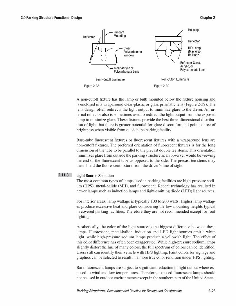
2.0 Parking Structure Functional Design Chapter 2
Parking Structures: Recommended Practice for Design and Construction 2-26
A non-cutoff fixture has the lamp or bulb mounted below the fixture housing and is enclosed in a wraparound clear-plastic or glass prismatic lens (Figure 2-39). The lens design often redirects the light output to minimize glare to the driver. An in-ternal reflector also is sometimes used to redirect the light output from the exposed lamp to minimize glare. These fixtures provide the best three-dimensional distribu-tion of light, but there is greater potential for glare discomfort and point source of brightness when visible from outside the parking facility.
Bare-tube fluorescent fixtures or fluorescent fixtures with a wraparound lens are non-cutoff fixtures. The preferred orientation of fluorescent fixtures is for the long dimension of the tube to be parallel to the precast double tee stems. This orientation minimizes glare from outside the parking structure as an observer would be viewing the end of the fluorescent tube as opposed to the side. The precast tee stems may then shield the fluorescent fixture from the driver’s line of sight.
2.11.3 Light Source Selection The most common types of lamps used in parking facilities are high-pressure sodi-
um (HPS), metal-halide (MH), and fluorescent. Recent technology has resulted in newer lamps such as induction lamps and light-emitting diode (LED) light sources.
For interior areas, lamp wattage is typically 100 to 200 watts. Higher lamp wattag-es produce excessive heat and glare considering the low mounting heights typical in covered parking facilities. Therefore they are not recommended except for roof lighting.
Aesthetically, the color of the light source is the biggest difference between these lamps. Fluorescent, metal-halide, induction and LED light sources emit a white light, while high-pressure sodium lamps produce a yellowish light. The effect of this color difference has often been exaggerated. While high-pressure sodium lamps slightly distort the hue of many colors, the full spectrum of colors can be identified. Users still can identify their vehicle with HPS lighting. Paint colors for signage and graphics can be selected to result in a more true color rendition under HPS lighting.
Bare fluorescent lamps are subject to significant reduction in light output where ex-posed to wind and low temperatures. Therefore, exposed fluorescent lamps should not be used in outdoor environments except in the southern part of the United States.
PendantMounting
Semi-Cutoff Luminaire
Re�ector
Clear Acrylic orPolycarbonate Lens
Clear PolycarbonateWindow
Non-Cutoff Luminaire
Re�ector
Refractor Glass, Acrylic, orPolycarbonate Lens
HID Lamp(May AlsoBe Horiz.)
Housing
Figure 2-38 Figure 2-39

2.0 Parking Structure Functional Design Chapter 2
Parking Structures: Recommended Practice for Design and Construction 2-27
In colder climates with average winter temperatures of 50 °F or less, a wraparound, clear acrylic lens should be used for protection from wind and low temperatures. The fixture should be vapor-tight and have an internal protection rating of 65.
The most energy-efficient and cost-effective fluorescent systems consist of T8 flu-orescent lamps or T5HO lamps with electronic ballasts. The “T” designation indi-cates the diameter of the lamp in eighths of an inch, i.e. a T8 lamp is 1 in. diameter and a T5 lamp is 5⁄8-in. diameter.
A fixture with four T8 lamps and normal power ballast is roughly equivalent in maintained light output to a 175-watt MH lamp or 150-watt HPS fixture, and uti-lizes only 110 input watts compared to 208 input watts for the MH and 188 input watts for the HPS fixtures. Therefore, the T8 fluorescent fixture saves 41 to 47% in energy use resulting in a substantial savings in operational cost on a one-for-one replacement basis. A fixture with two, T5HO lamps has approximately the equiva-lent maintained illuminance as the three fixtures mentioned previously. The T5HO fixture uses 123 input watts and therefore, saves 35 to 41% in energy cost compared to a 175-watt MH fixture or 150-watt HPS fixture. A 128-watt LED fixture has ap-proximately equivalent maintained illuminance to the four fixtures mentioned pre-viously, utilizes only 128 input watts and saves 32 to 38% in energy cost compared to the MH and HPS fixtures.
Even the enclosed fluorescent fixtures will lose over 20% light output at tempera-tures below 10 °F. Therefore, in extremely cold, northern climates, LED fixtures should be considered as they burn quite hot and dissipation of heat is more of a con-cern with LED fixtures. LED fixtures have a 100,000 hour life compared to 30,000 hours for fluorescent lamps. Therefore, maintenance costs will be less with LED fixtures compared to fluorescent fixtures.
Induction fixtures do not currently produce enough light output at the same wattage compared to other fixtures mentioned previously. For example, a 165-watt induction lamp produces approximately 75% of the light output compared to similar wattage fixtures. Thus, more fixtures are required to produce equivalent illuminance. There-fore, the energy costs are likely to exceed that of fluorescent or LED fixtures. The induction lamp does have a 100,000 hour lamp life, but the reduced maintenance cost will usually not cover the operating cost increase.
From a life cycle cost perspective, fluorescent and LED fixtures are considered to be the most cost-effective option for parking facility lighting. Currently, LED fixtures have a higher initial cost compared to fluorescent fixtures. As LED fixtures become more cost effective, fluorescent and LED fixtures will likely take over the lighting market for parking facilities from high-pressure sodium and metal halide.
2.11.4 Fixture Placement The spacing of precast concrete double tee stems most often dictates the placement
of light fixtures. A 10-ft-wide double tee with a tee stem spacing of five ft will result in a light fixture spacing on a five-ft module. However, placement of light fixtures below the flange joint of the double tees is not recommended, as inadequate mainte-nance of the joint sealant may result in water leakage that will damage the lighting

2.0 Parking Structure Functional Design Chapter 2
Parking Structures: Recommended Practice for Design and Construction 2-28
system. If fixture placement in the flange joint soffit is necessary, the light fixture should be offset to the uphill side of the joint. It is typical to cast openings in the double tee stems above the prestressing strand to allow for placement of continuous electrical con-duit for lighting. In order to minimize blockage of light, the light fixture should be mounted so the bot-tom of the fixture is a maximum of 6 in. above the bottom of the double tee stem. (Figure 2-40)
Figures 2-41, 2-42, and 2-43 show lighting configurations typically used for parking structures. The single row of light fixtures on the centerline of the drive aisle (Figure 2-41) generally is not recommended, as it is difficult to meet the IESNA maxi-mum-to minimum uniformity ratio or the vertical-illuminance criteria. The config-urations in Figure 2-42 and 2-43 are recommended for precast concrete double tee parking structures. The staggered configuration in Figure 2-43 illuminates more of the double tee stem soffits and thus provides for a brighter ceiling appearance. Also, painting the underside of the double tees will greatly enhance illuminance.
2.11.5 Electrical Equipment Room Electric metering and switching often requires a separate area or room in a parking
structure. This room may be a partitioned section of a storage room where mainte-nance equipment and supplies are kept. If the equipment room is not readily acces-sible to operating areas (cashier booths and office), remote switching of the lighting from the office or a cashier booth may be desirable.
Light Distribution
Figure 2-40
Fixture Locations
w/2
w/2
‘w’
w/2
w/4
w/4
‘w’
w/2
w/4
w/4
‘w’
Figure 2-41Single Row Lighting(Not recommended)
Figure 2-42Double Row Lighting
Figure 2-43Staggered Double Row Lighting

2.0 Parking Structure Functional Design Chapter 2
Parking Structures: Recommended Practice for Design and Construction 2-29
2.12 Wayfinding, Signage, and Graphics
2.12.1 Introduction This section will discuss the basic principles of wayfinding, signage, and graphics.
These are fundamental elements to the design of a parking facility and can have a significant impact on the user experience. It is both a science and an art. The science has principles that if not followed will lead to navigating challenges. The art aligns each element in a seamless fashion providing clear and concise information when needed.
Today’s parking structures are becoming more complex mixing multiple modes and destinations and often incorporating multiple zones for different parking groups. Successful navigation by both vehicles and pedestrians depends largely upon the functional design and its wayfinding, signage, and graphics design. The ability for a patron to easily find a space, determine their destination, and find their vehicle upon returning is a rudimentary function of a parking structure.
2.12.2 Wayfinding The purpose of wayfinding is to provide a logical guide for patrons to enter the
facility and navigate through the structure to locate a parking space. The driver then becomes a pedestrian and must determine a route to their destination. Upon returning, the wayfinding system guides the driver back through the structure to the point of exit. A well-functioning parking structure uses the human senses to provide direction, locate anchors or landmarks, and is repetitive in nature. These visual clues confirm that the correct path is being followed.
Proper consideration of the interior environment and wayfinding provide a series of clues that stimulate the senses. The environment surrounding an individual creates a mental image or cognitive map that contributes to spatial orientation. People who recognize their location within a setting or space are better able to plot a course through the space to get to their destination. Consistency in signage, graphics, inte-rior features, and even lighting can have a profound effect on spatial orientation for both the driver and pedestrian.
2.12.3 Signage Signage is the display of messages throughout a parking structure providing infor-
mation at key decision points. Signage plays a significant role in how both vehicles and pedestrians circulate through a parking structure.
The basic sign types are:
• Entry/Exits• Vehicular Wayfinding • Pedestrian Wayfinding• Stairs/Elevators/Level Indicators• Accessibility• Regulatory Signs• Illuminated Signs• Height Clearance

2.0 Parking Structure Functional Design Chapter 2
Parking Structures: Recommended Practice for Design and Construction 2-30
Sign messages should be simple and succinct. Messages on signs that are to be read quickly, such as vehicular signs, should be no more than 30 characters and six words in length. The typeface used should be simple and easy to read. Typical parking structure signage typography uses Helvetica, Universal, Optima, or Craw Clarendon. Helvetica is considered the most easily and quickly legible letterform. Studies have shown that signs with lower case letters and initial caps are most easily read. The simple block arrow is recommended for directional information. If a left turn is required, the arrow should be placed on the left side of the sign. The opposite is true for a right turn. Signs with a dark background and white letters are more easily read than signs with a white background and dark letters.
Emphasizing the entrance to a parking facility is important. Large illuminated signs are often used to emphasize the facility entry and attract patrons. These signs of-ten spell out “Parking” or use the international symbol for parking. Architectural features, such as an arch, canopy, or some different treatment of the façade, are often used to highlight the entry area as well. A height clearance bar is required for all parking structures. Generally, the height clearance bar is located at the facility entrance(s). There may be instances when the clear height in a parking structure changes from one level to another (for example, a higher ground level than typical level to accommodate ADA vans), which may require additional height clearance bars within the facility itself.
If vehicles are entering a structure at the top level or if the posted clearance is greater than 7'-0", it is suggested that a weight limit also be posted at the entrance to prohibit entrance by vehicles of excessive weight. Statistics show that most pas-senger cars and light trucks have a curb weight of between 3,000 to 4,500 pounds. Vans, heavy duty trucks, and large sport utility vehicles can have a curb weight of 6,000 pounds or more. Vehicle curb weights, however, do not include passengers, cargo, and fuel. Therefore, a posted load limit of 8,000-pounds may be appropriate to reflect a maximum gross vehicle weight.
Vehicular signage should direct the driver through the facility to a parking space and back to the exit upon departing. This sig-nage should be centered on the path of travel and placed as low as possible for visibility, but not lower than the maximum allowable vehicle height (Figure 2-44).
Drivers view signs from an approximate height of forty-five in. above the floor while pedestrians view signs from five to six ft. Clear heights and floor slopes can have an impact on sight distance thus reducing the effectiveness of the message. Figure 2-45 illustrates the sight distances on sloped floors. The most critical condi-tion is the downward slope as shown in Figure 2-46.
Sign Mountw/ Lighting
Maximum Vehicle Height
Figure 2-44

2.0 Parking Structure Functional Design Chapter 2
Parking Structures: Recommended Practice for Design and Construction 2-31
A combination of text, symbols, and arrows are the most effective means of com-municating the sign message. When used, symbols and arrows should follow the Manual on Uniform Traffic Control Devices (MUTCD)5. Pictograms are symbols or pictures that are used to communicate meaning. Only universally understood pictograms should replace words.
Pedestrian signage should direct the users from their parking space to the appropri-ate stair or elevator. Pedestrian signs should be clearly distinguishable from vehicle signs so as not to interfere with vehicular wayfinding. Pedestrian signs in parking bays are most effective if located perpendicular to traffic flow, and they should be placed above the rear of parking stalls. In addition to stair/elevator directional signs, pedestrian signs should be provided for direction to emergency assistance call sta-tions, as well as to specific destinations. Pedestrian signs can be all one color or be color-coded by level.
Regulatory signs are often used in parking facilities to enhance wayfinding or sat-isfy local requirements. These are typical street and highway signs such as stop signs, one-way, yield, no parking, do not enter, etc. When used, they should follow MUTCD guidelines.
Illuminated signs are becoming more common in parking structures and are useful in a variety of applications. At entry and exit locations, illuminated signs are partic-
Sight Distance at Level Approach
Sight Distance at Approach From Up Ramp
45"
45"
45"
Sight Distance at Approach From Down Ramp
Figure 2-45
Figure 2-46

2.0 Parking Structure Functional Design Chapter 2
Parking Structures: Recommended Practice for Design and Construction 2-32
ularly useful in guiding the driver into the appropriate lane when entering or exiting the facility. Backlit or LED illuminated signs are sometimes used at major decision points or pedestrian crossings to enhance user safety. Also, illuminated signs with variable messages are commonly used in larger structures in conjunction with space counting systems.
Specific signage designating accessible and van accessible spaces are required at each ADA parking space. ADA signage generally follows a national standard, but may vary slightly from state to state. ADA signage including Braille markings where applicable must be mounted in appropriate locations and follow local and national requirements.
In all cases, signs should be mounted securely to the supporting structure. Lighting should be coordinated with signage placement so that special sign lighting is not required. However, light fixtures should not be placed too close to the sign such that the glare will cause difficulty in reading.
2.12.4 Graphics Graphics are the messages that display information or provide large illustrations to
enliven and personalize public spaces. Graphics can be wall treatments, flags, ban-ners, directories, or murals. Graphics through their illustrations try to create a visual image in one’s mind, so one may recall that image. Graphics can play a significant role in how both vehicles and pedestrians circulate through a parking structure.
One problem that occurs in parking structures, especially in a continuous sloped structure, is patron confusion over where their car is parked. Large graphics in the stair and elevator lobbies denoting the floor and an indication for the parker to re-member the floor level should be provided. Memory joggers to help the parkers re-member their parking location are often used. Themes such as colors, local features, athletic teams, or animals can be used for designating each floor.
The art of graphics or themeing within a structure can aid in tying the environmental conditions to the cognitive map. However, using too many symbols, colors, or pat-terns may actually detract and just add to the visual clutter. Thus, themeing is more of an art than a science.
The industry has long favored color coding of parking levels. Many believe that primary colors such as red, orange, yellow, green, blue, and brown are the easiest to remember and the most distinguishable. White, black, gray, or blended colors such as teal or aqua are less effective and should not be used. If more than six colors are needed, a loss of effectiveness occurs. Additionally, if the levels are color coded, the elevator call buttons should be color coded to match the levels.
2.12.5 Pavement Markings Pavement markings include traffic arrows, stop bars, pedestrian crossings, no park-
ing zones, parking stalls, buffer zones, and accessible routes. They are most often yellow or white in color and often include silica sands or glass beads to enhance reflectivity and traction. The MUTCD includes the basic requirements for the place-ment and style of most floor painted graphics.

2.0 Parking Structure Functional Design Chapter 2
Parking Structures: Recommended Practice for Design and Construction 2-33
Parking stalls may consist of single or double stripes. Some parking professionals believe that double striping is more effective in encouraging the driver to center the car in the space. Single striping, however, is less costly and may still be effective in centering the car when using a high-quality reflective paint. Also, studies have shown that using a shorter stripe length (i.e. 17'-0" rather than 18'-0") encourages drivers to pull more forward in the stall giving the drive aisle a wider feel.
Striping should be provided where it is important to define pedestrian walkways, particularly in the vicinity of vehicular entries and exits so pedestrians will not use the vehicle aisles as pedestrian ways.
2.13 Other Items to Consider The preceding sections have discussed the major topics associated with the plan-
ning and functional design of an open parking structure. This section will briefly cover a few other topics that should be considered.
2.13.1 Fire Protection If a parking structure does not meet the requirements of an open parking garage as
defined by the IBC, the facility must meet the more stringent requirements of an enclosed parking garage. Mechanical ventilation and automatic sprinkler systems are required by the IBC for enclosed parking garages. These systems can be costly and should be avoided if possible. Also, height and floor area limitations are more restrictive for enclosed parking garages.
Mechanical ventilation systems consist of vent shafts equipped with large fans which move air through the facility at code specified rates. The systems are typi-cally controlled with carbon monoxide (CO) monitors that turn the fans on and off relative to the concentrations of CO. The International Mechanical Code6 includes the requirements for the system and prescribes the ventilation rates.
In open parking structures, a dry standpipe system is typically the only fire suppres-sion requirement. For enclosed parking structures and for stories and basements without openings, an automatic sprinkler system will be required. The International Fire Code7 provides the requirements for fire suppression systems. It should be noted that local fire marshals may require a higher level of protection than what is mandated by the building codes.
Portable fire extinguishers are required by the code for virtually all occupancies and no exception is given for parking structures, open or enclosed. In many cases, however, the local fire marshal makes an interpretation that the code requirement for proper training on the use of portable fire extinguishers cannot be accomplished in a public parking facility and it may be unsafe for an untrained person to attempt to control a vehicle fire with a portable fire extinguisher. Experience has also shown that fire extinguishers in public parking facilities are often stolen, so the likelihood of a unit available in an emergency is uncertain. Therefore, it is common for the local fire marshal to interpret the code such that a portable fire extinguisher is only to be provided in a manager’s office, cashier booth, security office, or storage room where they can be used by trained personnel.

2.0 Parking Structure Functional Design Chapter 2
Parking Structures: Recommended Practice for Design and Construction 2-34
2.13.2 Physical Hazards Fall accidents from tripping or slipping in parking
structures present a liability problem for owners and operators. The designer should pay particular attention to areas where sudden changes in grade, such as curbs and raised islands could cause a trip and fall. Raised islands in the vicinity of stair and elevator towers should be avoided. If used, raised islands should have their edges painted traffic yel-low (Figure 2-47) and appropriate ADA curb cuts provided. Similarly, precast concrete or recycled rubber wheel stops are not recommended (Figure 2-48), as they provide an area for trash and debris to collect, may be trip hazards, and are often dis-lodged by cars and snowplows.
As discussed in Section 2.9, stair towers and el-evator lobbies should be protected from the ele-ments. Also, non-slip surfaces such as broom fin-ishes should be used on all floor areas.
2.13.3 Vehicle Barriers and Pedestrian Guards The IBC requires that vehicle barrier systems be provided at the perimeter of sup-
ported levels, along each side of a ramp, and where there is an abrupt change in floor elevation. The barriers may be constructed of concrete walls, tensioned cables, or steel guardrails and must be able to resist an impact load of 6,000 pounds acting on an area of one foot square. The IBC now requires the barrier system to satisfy multiple loading conditions. Design of vehicle barriers is covered in more detail in Chapter 5.
For pedestrian fall protection, the IBC requires that guards be provided where floor surfaces are separated by 30 inches or more. Guards are generally provided by con-crete spandrels, railings, barrier strands, fencing, or a combination of materials. The code prescribed minimum height of 42 in. is measured from the highest point of the walking surface to the top of the railing. The guards must meet the code prescribed minimum requirements for strength. When open railings or barrier strands are used, the openings shall be arranged such that a 4 in. sphere will not pass.
2.14 Sustainability The functional design of parking structures plays a key role in
the sustainability of the facility. Providing preferential parking for electric, hybrid (Figure 2-49), and high-occupancy vehicles and providing bike storage are examples of sustainable practice as it relates to the functional design. Sustainability is discussed in greater detail in Chapter 4.
Figure 2-49
PaintTraf�cYellow
RaisedIsland
3"
Wheel StopIs Not
Recommended
Figure 2-47
Figure 2-48

2.0 Parking Structure Functional Design Chapter 2
Parking Structures: Recommended Practice for Design and Construction 2-35
2.15 Summary The objectives of the functional design of a parking structure are to create a facility
with a simple continuous traffic flow, parking spaces that are easy to park in, and an atmosphere that gives the user the feeling of safety and comfort.
For additional information regarding parking functional design, the following orga-nizations have parking related publications available through their websites:
National Parking Association1112 16th Street, N.W., Suite 840Washington, DC 20036Phone: 1-800-647-PARKwww.npapark.org
International Parking InstituteP.O. Box 7167Fredericksburg, VA 22404Phone: 540-371-7535www.parking.org
References
1. International Code Council. 2012. International Building Code. (IBC) Country Club Hills, IL.
2. International Code Council. 2009. Accessible and Usable Buildings and Facil-ities (ICC A117.1) Country Club Hills, IL.
3. Monahan, D.R. 2007. Precast Concrete Parking Structure Lighting Study, PCI Journal, V. 52, No. 6 (November-December): pp. 89-98.
4. Illuminating Engineering Society of North America. 2014. Lighting for Parking Facilities (RP-20-14). New York, NY.
5. Federal Highway Administration. 2009. Manual on Uniform Traffic Control Devices. Washington DC.
6. International Code Council. 2012. International Mechanical Code. (IMC) Country Club Hills, IL.
7. International Code Council. 2009. International Fire Code. (IFC) Country Club Hills, IL.

2.0 Parking Structure Functional Design Chapter 2
Parking Structures: Recommended Practice for Design and Construction 2-36

3.0 Durability Considerations Chapter 3
Parking Structures: Recommended Practice for Design and Construction 3-1
3.0 DURABILITY CONSIDERATIONS
3.1 Introduction Precast, prestressed concrete parking structures have been proven to be durable and
are well suited to areas where corrosion and freeze-thaw damage are potential prob-lems. The precast concrete industry has developed materials, designs, fabrication and erection practices, and details which provide economical, durable facilities for the harsh environments typically encountered. Recent technological advances in concrete mixture design allow flowable concrete at very low water-to-cementitious materials ratios providing durable concrete. Flowable mixes with water-to-cementi-tious materials ratio as low as 0.3 have become available in recent years. These mix-tures have relatively low permeability and therefore high resistance to undesirable ingress of moisture and chlorides. Also, curing can easily be accelerated in a plant to facilitate development of early age strength and other desirable concrete properties.
The primary structural reinforcing steel in precast stemmed deck components is typically located in the lower portion of a stem, a significant distance away from ingress of moisture, chlorides, and other contaminants. Reinforcing steel placement in plant conditions is better controlled than field-placed steel, resulting in a low likelihood of insufficient concrete cover. These factors provide additional means of improving the durability of precast concrete products. Combined with proper drainage, connections that allow for sealing against penetration of salts and water, and a regular maintenance program, precast, prestressed parking structures can be expected to remain in service for half a century or more.
3.2 Durability Factors The major factors affecting parking-structure durability are distress due to restraint
of volume change strains, deterioration from freeze-thaw cycles, corrosion damage from chloride exposure, poor drainage and inadequate maintenance. Cracking from loading in excess of design load can also contribute to diminished durability if not properly repaired.
In precast, prestressed concrete parking structures, dimensional-volume changes occur due to concrete shrinkage and creep and temperature changes. Shrinkage and creep strains slowly shorten members over time. In precast concrete members, a significant portion of the strain occurs before the products are erected, so any detri-mental effects will be limited to the portion of total shortening that takes place after final connections have been installed. Volume changes due to temperature varia-

3.0 Durability Considerations Chapter 3
Parking Structures: Recommended Practice for Design and Construction 3-2
tions, both daily and seasonal, will either shorten or elongate a member. Distress can occur if the resistance to volume change strains exceeds the ability of the fram-ing system, including its members and connections, to resist the associated induced stresses. Proper detailing with flexible, ductile connections has proven to control volume change distress in members being connected through these joints. Addi-tional material on the effects of volume changes in parking structures is covered in Section 5.4.
Climatic durability relates to the structure’s ability to withstand the effects of freeze-thaw action and deicing salts in colder climates, and the effects of airborne salt in coastal areas. Moderate-climate regions may experience more freeze-thaw cycles than where temperatures stay below freezing for longer periods. It also should be recognized that salt or other chemical agents can cause concrete-surface scaling.
ACI 318-111 and most international codes address concrete durability by an expo-sure class approach. Table 4.2.1 of ACI 318 defines four exposure categories that are subdivided into exposure classes based on the severity of anticipated exposure to freeze-thaw, sulfates, chlorides and moisture. Concrete mix requirements are speci-fied for each exposure class to enhance the durability of the concrete against specific corrosion mechanisms.
The code states the licensed design professional shall assign exposure classes based on the severity of the anticipated exposure. Different portions of a structure may have different exposure categories and classes. Standard precast concrete mixes and designs typically exceed the ACI durability requirements.
ACI 362 Committee2 in their recommendations for durable parking structures de-fines five distinct geographical exposure zones where climatic conditions are used to define minimum durability requirements. A map identifying the five zones is presented in Figure 3-1. The zones are defined as:
• Zone I represents the geographic area where exposure to freezing is rare and deicing salt is not used.
• Zone II represents the geographic area where exposure to freezing occurs and deicing salt is infrequently used.
• Zone III represents the geographic area where frequent exposure to freezing occurs and deicing salt is used.
• Zone CC-I represents the geographic area within Zone I subject to airborne chlorides and between one half (1⁄2) mile to 3 miles from a major saltwater body.
• Zone CC-II represents the geographic area within Zones I and II subject to air-borne chlorides and within one half (1⁄2) mile of salt water bodies.
Recommended durability detailing for each zone is listed in Table 3.1 and 3.2 for field and pretopped decks, respectively. For field-topped double tees, topping depth should be 2 in. to 3 in.. A minimum depth of 2-1⁄2 in. is recommended in Durability Zones II and III.

3.0 Durability Considerations Chapter 3
Parking Structures: Recommended Practice for Design and Construction 3-3
Figure 3-1
Durability Zones2

3.0 Durability Considerations Chapter 3
Parking Structures: Recommended Practice for Design and Construction 3-4
Design ElementExposure Zoneg
I II/CC-I III/CC-II
Topping Concrete
28 Day Strength psi 4000 4500 5000
Air, percenta Not requiredACI 318-11Table 4.4.1Class F1/F2
ACI 318-11Table 4.4.1Class F3
Precast Concrete
w/cmb ratio (maximum) 0.45 0.40 0.40
Strength, psi 5000 5000 5000
Air, percenta Not requiredACI 318-11Table 4.4.1Class F1/F2
ACI 318-11Table 4.4.1Class F3
w/cm ratio (maximum) 0.40 0.40 0.40
Minimum reinforcement cover in inches c,d,e
CIP – topping-top & edge 11⁄2 11⁄2 2
PC – slab bottom 3⁄4 3⁄4 3⁄4i
PC – Beam side & bottom 11⁄4j 11⁄4j 11⁄2
Precast column 11⁄4j 11⁄2 11⁄2
Walls (exposed face) 3⁄4 11⁄2 11⁄2
PCb ends See note d See note d See note d
PCb flange edge connectorsRust
preventive paint or EPb
HDGb or SSb or EPb SSb
PCb exposed platesRust
preventive paint or EPb
ECb,f or HDGb or EPb
ECb,f or HDGb or EPb
Sealer h,k Roof onlyAll floors and
roof
Table 3.1 – Recommended durability detailing precast concrete with CIP topping
a Measured at point of discharge. Only required in freezing temperature regions. If f'c > 5,000 psi, the required air content is reduced by 1%.b Nomenclature: EC = epoxy-coated; EP = electro plated; HDG = hot dip galvanized: SS = stainless steel; PC = precast concrete; w/cm = water/ce-mentitious material.c Fire-resistive considerations may require greater bottom cover than noted herein. Also see ACI 318 section 7.7 for cover of No. 6 through No. 18 bars in concrete exposed to weather.d Ends of strands shall be protected in all Zones.e Cover is specified to any reinforcement, including stirrups, support bars and ties. Also applies to stairs.f Only the exposed plate need be epoxy coated; the anchors to the plate are not required to be epoxy coated. g Refer to section 3.2 for a definition of the exposure zone.h Silica fume, other pozzolans, corrosion inhibitors, or other means may be used in lieu of sealer application if the permeability of that concrete is determined to be low by acceptable standards. i The cover for CC-II should be 1".j If average prestress force is less than 225 psi, a 1-1⁄2" cover is required.k Sealer is not required if non-metallic or stainless steel top reinforcement is used to reinforce the topping, provided a minimum top cover of 2 inches to all other reinforcement is maintained in the member.
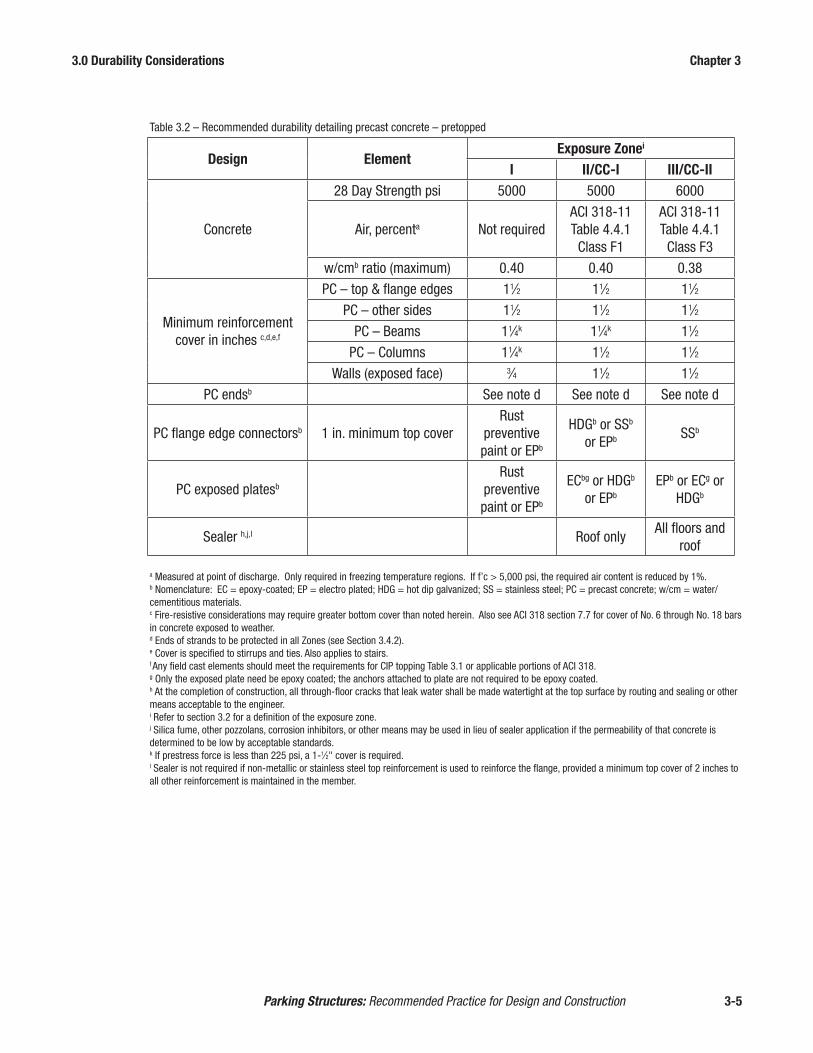
3.0 Durability Considerations Chapter 3
Parking Structures: Recommended Practice for Design and Construction 3-5
Table 3.2 – Recommended durability detailing precast concrete – pretopped
Design ElementExposure Zonei
I II/CC-I III/CC-II
Concrete
28 Day Strength psi 5000 5000 6000
Air, percenta Not requiredACI 318-11Table 4.4.1Class F1
ACI 318-11Table 4.4.1Class F3
w/cmb ratio (maximum) 0.40 0.40 0.38
Minimum reinforcement cover in inches c,d,e,f
PC – top & flange edges 11⁄2 11⁄2 11⁄2
PC – other sides 11⁄2 11⁄2 11⁄2
PC – Beams 11⁄4k 11⁄4k 11⁄2
PC – Columns 11⁄4k 11⁄2 11⁄2
Walls (exposed face) 3⁄4 11⁄2 11⁄2
PC endsb See note d See note d See note d
PC flange edge connectorsb 1 in. minimum top coverRust
preventive paint or EPb
HDGb or SSb or EPb SSb
PC exposed platesb
Rust preventive paint or EPb
ECbg or HDGb or EPb
EPb or ECg or HDGb
Sealer h,j,l Roof onlyAll floors and
roof
a Measured at point of discharge. Only required in freezing temperature regions. If f’c > 5,000 psi, the required air content is reduced by 1%.b Nomenclature: EC = epoxy-coated; EP = electro plated; HDG = hot dip galvanized; SS = stainless steel; PC = precast concrete; w/cm = water/cementitious materials.c Fire-resistive considerations may require greater bottom cover than noted herein. Also see ACI 318 section 7.7 for cover of No. 6 through No. 18 bars in concrete exposed to weather.d Ends of strands to be protected in all Zones (see Section 3.4.2).e Cover is specified to stirrups and ties. Also applies to stairs.f Any field cast elements should meet the requirements for CIP topping Table 3.1 or applicable portions of ACI 318.g Only the exposed plate need be epoxy coated; the anchors attached to plate are not required to be epoxy coated.h At the completion of construction, all through-floor cracks that leak water shall be made watertight at the top surface by routing and sealing or other means acceptable to the engineer.i Refer to section 3.2 for a definition of the exposure zone.j Silica fume, other pozzolans, corrosion inhibitors, or other means may be used in lieu of sealer application if the permeability of that concrete is determined to be low by acceptable standards. k If prestress force is less than 225 psi, a 1-1⁄2" cover is required.l Sealer is not required if non-metallic or stainless steel top reinforcement is used to reinforce the flange, provided a minimum top cover of 2 inches to all other reinforcement is maintained in the member.

3.0 Durability Considerations Chapter 3
Parking Structures: Recommended Practice for Design and Construction 3-6
3.3 The Deterioration Mechanisms The deterioration sometimes found in reinforced concrete in parking structures has
two common sources: freeze-thaw damage and reinforcement corrosion. A discus-sion of the actions of these mechanisms causing damage is useful in considering effective prevention.
When concrete is damp, freezing temperatures can cause ice to form in the paste or matrix between the coarse aggregates. Ice expands to a volume roughly 9% greater than liquid water, causing internal stresses from hydraulic pressure in the pores. Concrete in parking garage construction is specified with a low water-cementitious ratio to reduce permeability and with air entrainment for a well distributed void structure that can absorb the expansion.
Deicing chemicals with chlorides (NaCl, CaCl2 and MgCl
2) can promote the early
corrosion of embedded steel parts or reinforcement. The high alkalinity of con-crete (pH between 12 and 13) protects embedded steel by a passivating layer of the surrounding concrete. However, when moisture and oxygen are present, “the presence of water-soluble chloride ions, above threshold levels of 0.2% (0.4% cal-cium chloride) by mass of portland cement, can accelerate corrosion.”3 “Corrosion is an electro chemical process requiring an anode, a cathode and an electrolyte. A moist concrete matrix forms an acceptable electrolyte and the steel reinforcement provides the anode and cathode.”4 This process results in the formation of iron oxide (rust) that has much greater volume than the underlying base metal. The expansion creates internal pressure in the concrete that causes the concrete to crack and delam-inate. This action further exposes the steel so that the corrosion accelerates.
There are several potential sources of chloride ions in concrete. Chloride may exist in cement compounds or in aggregates. Certain concrete admixtures contain chlo-rides as can mixing water, but these sources do not normally contain significant amounts of corrosion-causing chloride. ACI 318 establishes limits for new concrete of 0.15% of water-soluble chloride ions by weight of cement for weather-exposed reinforced concrete poured in the field, but only 0.06% for prestressed concrete. In northern climates, the most common source of chlorides is deicing salts. In coastal areas, airborne salt from the ocean can also cause corrosion.
The action of freeze-thaw deterioration and reinforcement corrosion can cause se-vere damage especially in surfaces that are over-finished, covered by standing wa-ter, poorly detailed or improperly maintained. This emphasizes the importance of proper planning and detailing to minimize the effects of these potential deteriorat-ing mechanisms.
3.4 Designing for Durability Durable parking structures are developed by specifying the proper materials, de-
tails, design and construction techniques for a specific environment. Criteria to be considered in the design of any parking structure include:
• concrete quality and permeability• proper surface drainage• concrete cover over reinforcement

3.0 Durability Considerations Chapter 3
Parking Structures: Recommended Practice for Design and Construction 3-7
• surface sealers• construction joint and control-joint sealants• corrosion inhibitors• connection materials• reinforcing materials
3.4.1 Concrete Quality Concrete performance is generally defined in terms of durability. The primary solu-
tion for durability is high-quality concrete having a minimum compressive strength of 5000 psi with durable hard-rock aggregates having good abrasion resistance. In more definitive terms, high-quality concrete design must incorporate consider-ations for the following parameters: strength, permeability, durable aggregates, and air entrainment.
Concrete strength above 5,000 psi can be obtained through the proper balance of cementitious content and water/cementitious ratio. While geographical differences in material availability and performance exist, cementitious contents in the 600-700 lbs per cubic yard range and water/cementitious ratios in the 0.40-0.45 range will usually result in strengths above 5,000 psi. Higher strength, with a corresponding lower permeability, is achieved with high cementitious content and a lower water/cementitious ratio, sometimes augmented by the use of fly ash, slag, or silica fume.
To effectively limit permeability of floor-slab concrete, the water/cementitious ratio should not exceed 0.40 for concrete exposed to chlorides from deicing chemicals, salt or sea water. For even lower permeability in corrosive environments, water/cementitious ratios between 0.32 and 0.40 can be achieved readily through the use of high-range water reducing admixtures in the concrete mix. This is common prac-tice for plants that produce pretopped double tee members. Studies5,6 have shown that the concrete water cementitious ratio (w/cm) is the dominant factor in reducing chloride permeability. Lowering the w/cm ratio from a level between 0.46 to 0.51 to a level between 0.37 to 0.40 reduced the chloride content at a depth of 1 in. after severe 1-year saltwater exposure by about 80%.
Aggregates, along with proper gradation, play a major part in the determination of concrete quality. Durable aggregates possessing proper hardness, soundness, and low absorption are recommended for both compressive strength and abrasion resis-tance. Air entrainment should be in accordance with Table 3.1 and 3.2. In addition, good concreting practices as defined in ACI7 or PCI documents8 are necessary.
Alkali-silica reactivity (ASR) is caused by the reaction between hydroxyl ions in cement and reactive forms of silica in the aggregates. Aggregates should be tested to determine if they contain materials that are deleteriously active with alkalis in the ce-ment in an amount sufficient to cause excessive expansion. If reactive aggregates are found, the concrete mixture can often be modified with the addition of Class F fly ash, other supplementary materials, or admixtures to mitigate the deleterious reactions.
Another chemical mechanism that can cause expansion in the concrete matrix in the presence of water is delayed ettringite formation (DEF). Acceleration of DEF can occur in the presence of ASR. The risk of DEF can be reduced by proper cur-

3.0 Durability Considerations Chapter 3
Parking Structures: Recommended Practice for Design and Construction 3-8
ing. Heat should not be applied to the concrete until after initial set. The concrete should not be cured at a temperature exceeding 158° F unless measures are taken to mitigate potential development of DEF and ASR.
3.4.1.1 Deck Surfaces In order to provide durability, field-cast, concrete-wear surfaces should have the
qualities described above and should be placed using proper methods. Specifica-tions must be strictly adhered to. Minimum strength and cover for field placed topping should follow Table 3.1 recommendations.
Prior to placing topping concrete, the joints between the tee flanges and tee ends should be covered or sealed to prevent concrete leakage. Since a joint cover will debond the topping from the precast, the width should be kept to a minimum, typ-ically less than 2" each side of the joint and approved by the licensed design pro-fessional. Sealing the joint with a backer rod eliminates debonding of the topping at the edge of the tee, but requires proper installation to remain in place over time. Some of the details to promote bond of the topping concrete include a thorough cleaning of the precast deck unit and wetting of the precast surface prior to plac-ing the concrete. Joints in precast will almost always cause reflection cracks in the overlying topping. It is important to place tooled joints in the topping over the precast joints (Figure 3-2) to provide a defined line for shrinkage and temperature movement. Tooling of joints must occur before the topping concrete has started initial shrinkage. It is critical the joints be tooled and not saw cut because shrinkage cracks usually form before the sawing operation and joint saws often cannot com-plete cuts because of obstructions at columns, walls, and spandrels. The joints then are filled with a properly installed elastomeric joint sealant. Details of the joint seal, tooled joint and topping concrete need to be coordinated to provide a single joint in the topping concrete that is located directly above the precast joint.
Sealant in tool joint Cast in place topping slab
Potential crack location
Figure 3-2

3.0 Durability Considerations Chapter 3
Parking Structures: Recommended Practice for Design and Construction 3-9
An alternative to using field-placed topping concrete is to specify a plant-produced, pretopped precast concrete structure. Pretopped precast concrete members general-ly are air-entrained with strengths in excess of 5,000 psi and have enhanced durabil-ity associated with a low water/cementitious ratio. Since the pretopped tee surfaces become the final wearing surfaces in the parking structure, plant produced products take advantage of good concreting practices and quality control procedures that are typically more difficult to achieve with concreting operations in the field. Plant op-erations provide good control of dimensions, curing to reduce shrinkage, cracking, and crazing, and other quality processes to create durable concrete surfaces.
3.4.1.2 Finishing Finishing the concrete is also critical. The key to durability is to minimize finish
working of the concrete and to maximize curing, so as not to disrupt the matrix at the surface and drive out moisture needed to hydrate the cement at the surface. Minor roughness is desirable to improve traction. A hard-troweled finish should be avoid-ed. Precast surfaces that are field-topped are typically roughened by using a rough broom or rake on the fresh surface. Pretopped tees usually have a broom finish.
Final finishing of field-placed topping concrete should not commence until the bleed water has disappeared. Early finishing drives bleed water back into the sur-face, increasing the water/cementitious ratio in the critical top layer, and greatly increasing the probability of surface scaling later. The low water/cementitious mix used in precast plants minimizes this problem, because very little bleed water exists and finishing can proceed quite rapidly. When a finishing machine is employed, screeding and finishing are combined into a single operation.
3.4.1.3 Curing Curing methods depend on weather conditions. Enough moisture must be present to
hydrate the cement, but excess moisture must be allowed to escape prior to sealing the concrete surface. With low water/cementitious-ratio concrete, an evaporation retarder is often applied to the concrete surface during the finishing stage to reduce evaporation and prevent plastic shrinkage cracking.
Studies5 have shown the benefits of heat curing in the durability characteristics of a concrete mix compared to concrete cured in a water tank or with wet burlap. Heat-cured conventional concrete has lower water absorption, chloride absorption and less volume of permeable voids.
3.4.2 Drainage Proper drainage of the parking structure floors is mandatory, to eliminate pond-
ing water which promotes the absorption of deleterious chlorides into the concrete. Minimum slopes in two directions are necessary to achieve positive drainage to avoid ponding water.
Slopes of 11⁄2% are common with 1% being the minimum acceptable field limit after construction tolerances are considered (Figure 3-3). Pitch is necessary to help ensure positive drainage and to overcome the effects of finishing tolerance, camber, and surface irregularities. Cross-bay drainage can best be achieved by raising one end of floor members. At the low end, lateral drainage can be achieved by:

3.0 Durability Considerations Chapter 3
Parking Structures: Recommended Practice for Design and Construction 3-10
1. Pitching the supporting girder or spandrel.
2. Sloping structural topping.
3. Sloping the bearing support of the floor double tees at both ends.
4. Twisting or warping the precast floor units, provided they are sufficiently flexi-ble. 1%-1-1⁄2% can typically be achieved for pretopped members that span over 50 feet. Thin flanged, topped tees can be warped to a greater degree.
Warping of double tees will produce tensile stresses in the top of the flange at one stem and in the bottom of the flange at the adjacent stem9. The magnitude of stress is dependent on the length and stiffness of the tee along with the degree of twist. Stud-ies10 have shown the magnitude of stress created by warping can be estimated such that crack widths can be controlled. If the stiffness of a member prohibits adequate drainage with warping, additional lateral drainage can be achieved by sloping both ends of a tee, as shown in Figure 3-3B.
The camber of the main floor members, usually double tees, requires careful con-sideration regarding drainage. This is particularly true when the designer desires to minimize the number of floor drains. Designers cannot depend on camber of the prestressed members to provide drainage slopes.
When pretopped double tees are used, care must be taken to eliminate differential camber offsets at the adjoining edges of members that may trap water.
On continuous ramp parking structures, the drains and drain lines typically are kept on the interior column lines to minimize the architectural impact of the vertical drain line on the exterior. This also minimizes the cost of the drainage system.
Vertical drain lines (downspouts) should be protected from vehicle bumper damage with a bumper guard around the drain line or by locating the drain line in a protected location (Figure 3-4). In hurricane areas, edge-relief scuppers can prevent structural overloading if a floor drain is clogged. When locating drain lines, architectural ap-pearance also must be considered.
Figure 3-3
A.) Drainage plan using warped double tees B.) Drainage plan with no warping of double tee
Elev. 99.33
61 ft
0 in
.
Elev. 99.00 Elev. 99.33
36 ft 0 in. 36 ft 0 in. 36 ft 0 in. 36 ft 0 in.
Elev. 100 ft 0 in.
DrainMin. slope
Min. slope
Drain
Elev. 100.42. Elev. 100.42Elev. 99.92
Min.
slop
e
Min.
slop
e
61 ft
0 in
.
Elev. 99.00 Elev. 99.50Elev. 99.50

3.0 Durability Considerations Chapter 3
Parking Structures: Recommended Practice for Design and Construction 3-11
3.4.2.1 Drains Positive drainage slopes in the immediate vicinity of floor drains is important. Floor
drains often are set 1⁄2 in. to 1 in. lower than the surrounding floor slab to ensure the concrete finishers will slope the floor positively down into the drains rather than leaving a “bird bath” adjacent to the floor drain. Drains generally are located near columns and at the bottom of the ramps throughout the structure. Coordination is required to ensure drains and drain lines do not interfere with structural connections between the column and the floor members. Also, if lateral runs are required, they must not fall within the critical bearing area of any structural member.
Floor-drain openings provided in the double tee flanges should be totally within one member if possible. Trying to match portions of precast openings cast into ad-jacent members creates match-tolerance problems and usually is not feasible unless sufficient tolerance is provided. If located within one member, drain rims can be cast into the precast flange and the drain body can be installed in the precast plant (Figure 3-5). The slab portion of stemmed members should be reinforced locally where large drains are installed. Square or round floor-drain openings are preferred to trench drains, which cut a large structural section out of a double tee flange. Trench drains may be used at the bottom of a roof level ramp, but full-length trench drains are not recommended as they interfere with the continuity of the structural diaphragm.
3.4.3 Concrete Cover The amount of concrete cover over the reinforcing steel is primary in importance
for delaying deicing salts deteriorating effect. Horizontal deck surfaces and vertical surfaces potentially exposed to deicing salts are surfaces that should be taken into consideration. Tests have shown that concentrations of deicing salt in older parking
Figure 3-4Drain Pipe Bumper Protection
Figure 3-5Cast-in Floor Drain

3.0 Durability Considerations Chapter 3
Parking Structures: Recommended Practice for Design and Construction 3-12
structures may be above 1,000 parts per million (ppm) in the upper surfaces of the concrete but will decrease with depth into the concrete. The threshold level for the initiation of corrosion in reinforcing steel is approximately 300-400 ppm of chlo-ride ion in the concrete, so the objective is to keep the concentration below that level.
The ACI Building Code, ACI 318, recommends a cover of 2 in. for reinforcing steel in cast-in-place concrete subject to deicing salts and 1-1⁄2 in. in precast concrete. In areas where slabs are not exposed to deicing salts but are exposed to the weather, the cover recommendation is 1-1⁄4 in. For prestressed members designed to crack under full service loads, classified per ACI 318 as Class T or C, concrete cover should be increased 50% in corrosive environments. The 50% increase can be waived if the precompressed tensile zone is not in tension under sustained loads. Tables 3.1 and 3.2 provide minimum cover requirements for various exposure zones.
Double tee floor members have their primary reinforcement – the strand – located in the stems, well below the deck surface. Consequently, chloride penetration does not present a problem for this reinforcement and increasing concrete cover by 50% when net tensile stress exceeds 7.5 fc
' is not required for stem reinforcement. Top flange stresses should be checked independently to determine if increased cover is required in the flange.
3.4.4 Concrete Surface Sealers Concrete surface sealers reduce moisture and salt penetration into parking structure
floor surfaces or other concrete members being treated. While these sealers can enhance the durability characteristics of any concrete topping to which they are applied, they do not provide a substitute for basic durable concrete design. They also do not provide protection against penetration of moisture and chlorides through cracks. Use of surface sealers can enhance durability performance and should be considered when decreased concrete permeability is desirable. With current con-cerns over volatile organic compound (VOC) emissions from sealers, other meth-ods, such as water based sealers, should be evaluated to reduce concrete permeabil-ity and increase corrosion resistance if specified sealers do not conform to state and local VOC emission standards.
Research has shown the performance characteristics of concrete sealers will vary greatly depending on the particular product used, as well as other variables. Prod-ucts should be evaluated against the criteria established in NCHRP 244 Series II & IV11.
Sealers generally may be classified into two groups: penetrants and surface sealers.
3.4.4.1 Penetrating Sealers Penetrants, generally silanes or siloxanes, provide protection by penetrating the sur-
face, reacting with the cementitious materials in the concrete, and creating a thin hydrophobic layer on the surface, but they do not have crack-bridging capabilities. Silane and siloxane sealers are longer lasting and less subject to wear under traffic and from exposure than other sealer alternatives. For good wear performance forty percent solids usually is recommended. For better wear performance at a slight

3.0 Durability Considerations Chapter 3
Parking Structures: Recommended Practice for Design and Construction 3-13
increase in cost, 100% solid sealer is sometimes specified. Because both finish and appearance are generally unaffected by application of these sealers, it is difficult to monitor their performance visually. Under heavy use, the hydrophobic layer may deteriorate, requiring re-treatment. Concrete moisture absorption testing or powder samples for chloride testing at incremental depths may be taken every three or four years to monitor performance. Testing for moisture transport properties of concrete can establish the performance of the concrete with and without the sealer. Establish-ing the depth of penetration of the sealer, reduction in absorption and monitoring the wear in the concrete surface will increase the time between testing. Bridge decks with snow plows and truck traffic have sealers reapplied at 5 year intervals; however, normal wear in a parking deck is typically much less than on a bridge. Absorption testing also monitors the concrete surface capability to protect against chloride infil-tration in advance and allows corrective action before the chlorides reach high levels.
3.4.4.2 Non-penetrating Sealers Non-penetrating sealers are generally polymer resins such as urethanes, epoxies,
acrylics or other proprietary blends. Manufacturers’ recommendations should be followed so that proper traction is achieved. They protect by penetrating slightly into surface pores and/or by providing a tough continuous film over the surface to which they are applied, but they may not bridge cracks. These sealers are more likely to change the appearance and traction of the floor surface and are subject to wear under traffic. They provide an alternative for areas where traffic or sunlight exposure isn’t a factor, such as in covered parking-stall areas and secondary-traffic aisles. Because a surface film generally is in evidence, performance can be moni-tored visually and areas can be resealed on a spot basis as needed.
3.4.4.3 Geographic Considerations The decision to use a concrete sealer on a precast, prestressed concrete project typi-
cally depends on its geographic location, whether a topping is incorporated into the design, and its service environment. Sealers generally are used when the structure will be exposed to freeze-thaw conditions, deicing salts, or ocean salt water. These conditions generally diminish in severity as one moves south to warmer climates or inland from the coast. See Tables 3.1 and 3.2.
3.4.5 Crack Prevention, Control Joints and Isolation Joints Deterioration of slabs and corrosion of reinforcing steel can accelerate in areas
where cracking occurs. Cracking will allow rapid access of deicing salts to the re-inforcing steel, particularly through cracks in line with the bars. Typically, precast, prestressed concrete parking structures have exhibited a higher degree of durability than cast-in-place concrete parking structures. Precast concrete strengths of 6,000 psi are common, promoting higher durability through denser concrete. Also, it is found that these higher-strength precast slabs maintain their integrity and function as uncracked sections in the service load range, creating greater durability. A PCI funded report12, showed this to be true in a survey of existing structures.The presence of cracks does not necessarily lead to accelerated corrosion of rein-forcing13. Studies have shown that while cracks may accelerate the onset of corro-sion, such corrosion is localized, particularly where the crack is perpendicular to the reinforcement. Further, studies14 have shown that static cracks less than about 0.012 in. wide have little influence on the long term corrosion process.
3.0 Durability Considerations Chapter 3
Parking Structures: Recommended Practice for Design and Construction 3-14
3.4.5.1 Construction and Control Joints Structures often must be built with control joints and construction joints. Field
placed topping must have control joints over joints between the precast units to pro-vide a defined line for shrinkage and temperature movements. These joints should be hand tooled, and have the proper cross section to ensure proper joint action. A high quality traffic-bearing polyurethane or silicone sealant is necessary to prevent intrusion of salts into these joints and to prevent subsequent deterioration of em-bedded metals. Depending on the degree of exposure, silicone sealants may provide greater longevity. As a backup in case of sealant failure, all metal passing through the joint should be treated per the recommendations of Tables 3.1 and 3.2 based on the geographical exposure zone. Section 3.5 provides additional joint sealant con-siderations.
3.4.5.2 Isolation Joints Isolation joints (expansion joints) are provided in parking structures to relieve the
stresses associated with volume-change forces (see Section 5.4). These joints are characterized by a complete break through the full cross section of the structure, al-lowing substantial movement to occur without harmful effects. Deterioration of un-derlying structural elements and leakage can be expected when these expansion joints are not sealed properly. Connections are required between adjacent members at a joint to transfer vertical shear and limit differential deflections to provide a smooth driving surface and limit vertical movement in the joint material.
3.4.6 Additional Durability Measures Where the deteriorating effects of deicing salts and ocean salts are prevalent, addi-
tional protective measures should be considered. The optimum first line of defense, as discussed elsewhere in this chapter, is dense concrete with low permeability. In the past, lowering the water cement ratio had the greatest impact and economics of any of the alternatives. Beginning in the 1990’s, high performance concrete mix-tures began to be regularly developed for specific characteristics needed in park-ing structures. To meet these demands, there is a trend toward performance based specifications to give the local producer the ability to optimize the concrete for the materials available and the requirements of the project. Advances in modeling of concrete performance and testing allow the comparison and evaluation of materials, economics, and performance. Some of these alternatives may include:
• increased concrete cover to reinforcing steel, • epoxy-coated reinforcement in field placed concrete, • carbon fiber reinforcement, • galvanized, zinc plated or stainless steel connections, • application of traffic-bearing membranes, • corrosion inhibitors • fly ash, slag, or silica fume, as supplementary cementitious materials (SCM’s).
An increase in cover is significantly more effective when low water cementitious ratio concretes are used. This compounds the benefits offered by a precast system in several ways. The flange reinforcing in a pretopped double tee is utilized to distrib-ute the concentrated loads a relatively short distance to the vertical stems. This re-inforcement is well protected by the dense concrete in which it is contained and by

3.0 Durability Considerations Chapter 3
Parking Structures: Recommended Practice for Design and Construction 3-15
the generous cover accommodated by the small cross section of steel and the four in. thickness of concrete flange. The stems contain the primary flexural reinforcing, typically prestressing strands, which are located well below the deck surface and thus, well away from exposure to the corrosive elements. As they are cut flush to the end, strands are typically coated with a zinc-rich compound or bitumastic material for protection.
The use of each of the above is only for those members expected to be in contact with chloride laden moisture, such as the deck double tee flanges and stems of in-verted tee beams. It would not be practical to pour the same member with different mixes. For the stems and flange of a tee for example, the entire member would receive the same concrete. Concrete mixture optimization can address durability, environmental or sustainability requirements, however, the effort must be coordi-nated with the local precaster. For example, it has been demonstrated that simply specifying the use of silica fume in prestressed precast concrete products for desired structural properties has not provided the desired incremental value, and therefore is typically avoided for reasons of cost and difficulties within the fabrication process. For example, the limited structural benefits of silica fume in precast, prestressed concrete components are typically not considered sufficient to justify the added cost and production difficulty when using this material.
3.4.6.1 Epoxy-Coated Reinforcement Epoxy coating isolates the reinforcing steel and can prevent the migrating chloride
ions from coming into direct contact with steel. This prevents the development of corrosion cells and greatly reduces the possibility of rusting. When epoxy-coated reinforcement is used, tie wire and other accessories also must be epoxy-coated. Caution should be exercised in using any epoxy-coated reinforcement. Increased bond lengths are required due to the smooth surface finish that is created resulting in larger crack sizes than experienced with uncoated reinforcement. Also, due to low melting temperatures, epoxy coatings should not be used in members subject to fire. Epoxy-coated strand is not used for parking structure applications, even in severe exposure conditions, due to the distance from the surface to the strand location. Where additional protection is desired for the deck, other methods may be more beneficial than using epoxy coatings and should be considered (e.g., increasing cov-er, low water/cementitious ratio, corrosion inhibitors, and sealers).
3.4.6.2 Traffic-Bearing Membranes Elastomeric deck-coating and membrane systems (Figure 3-6) protect concrete
against deterioration from the intrusion of water-borne chloride ions and freeze-thaw action as well as against leakage. These systems have gained widespread use in protecting cast-in-place reinforced-concrete structures because of the high inci-dence of corrosion related deterioration with this type of structural design. Because precast, prestressed parking structures have high durability characteristics, using these membrane systems to protect against deterioration and leakage generally is not required. Sometimes, situations arise where occupied space exists immediately beneath the parking area and the use of an elastomeric traffic-bearing coating sys-tem is recommended. Membranes can also be used as a remedial measure if CIP topping has deteriorated to the extent that excessive moisture or chlorides are reach-ing the underlying members or connections.

3.0 Durability Considerations Chapter 3
Parking Structures: Recommended Practice for Design and Construction 3-16
Traffic-bearing membranes typically consist of a multi-layer elastomeric polyurethane or neoprene material with an integral, nonskid traffic topping. In addition to provid-ing superior waterproofing protection to concrete sealers, the elastomeric properties of these systems allow them to successfully bridge small cracks. Due to potential movement of the joints, field-topped double tees with a membrane are recommended over occupied spaces. Membranes can be used over pre-topped double tees provided proper detailing is provided for joint movement. All membranes must be inspected periodically to ensure any tears or complete wear of the membrane are repaired to prevent the seepage of water and deicing salts into the concrete being protected.
If a lower-cost alternative is desired (to reduce a greater risk of leakage), overlaying each double tee edge joint with a 6 inch wide strip of waterproofing membrane will add protection to the typical sealant-joint detail.
3.4.6.3 Corrosion Inhibitors Corrosion inhibitors offer protection to embedded reinforcement and prestressed
strands. These admixtures either act on the steel surface to inhibit chloride-induced corrosion electrochemically (anodic, cathodic, mixed-inhibitor) or chemically (chemical barrier). A corrosion inhibitor delays the initiation of corrosion, reduces the corrosion rate, and may extend the structure’s service life. Corrosion inhibitors are being used by some highway departments as an admixture to protect precast concrete structural elements for bridges and cast-in-place concrete decks against deterioration due to deicing salts. It also is a corrosion-protection method for park-ing and marine structures.
One type of corrosion inhibitor that has seen extensive use is calcium nitrite, which reacts with the steel in the concrete and creates a protective electrochemical barrier. Quantities of calcium nitrite can be varied in proportion to the level of corrosion protection desired. Higher quantities can have an adverse effect on the workability and setting characteristics of the concrete.
Figure 3-6 Application of Deck Membrane

3.0 Durability Considerations Chapter 3
Parking Structures: Recommended Practice for Design and Construction 3-17
Other compounds reported as corrosion-inhibiting additives include borates, chro-mates, molybdates, nitrites, and hypophosphates. They offer varying levels of pro-tection depending upon their application and formulation. In all instances, the man-ufacturer should be contacted to verify appropriateness of applications and level of performance.
3.4.6.4 High Performance Concrete High performance concrete is a term used to describe concrete with special per-
formance and uniformity characteristics that cannot always be achieved routinely when using conventional materials and practices. Specific characteristics will vary depending on a particular application or environment. Mixes specifically formu-lated for one or more characteristics such as high early or design strength, low shrinkage, toughness, reduced permeability, ease of placement, scaling resistance or resistance to a severe environment, are considered high performance concrete.
With high concrete strength, low water/cementitious ratios and custom aggregate proportions, the majority of precast parking structures use high performance du-rable concrete. When enhanced durability is required for severe corrosive environ-ments, precast concrete mixes can easily be adjusted with commonly used admix-tures for superior performance. Section 7.1.1 describes commonly used admixtures.
3.4.6.5 Protection for Precast Connections Depending on the degree of exposure shown in Figure 3-1, plates should be coated
with rust inhibitive paint, epoxy painted, galvanized, zinc plated based on ASTM B63315, or made from stainless steel to prevent long-term deterioration. The protec-tion should be mandatory where plates cannot be reached in the future for protective maintenance. Welding of galvanized or electrode plated material requires removal of zinc in the weld area prior to welding except if an AWS qualified welding proce-dure is specified. After welding, slag should be removed and the weld area coated with a liquid galvanizing organic zinc rich coating, after the steel has been scoured with a stiff wire brush. The coating should contain 95% metallic zinc by weight in the dried film.
3.4.6.6 Precast Stair Units Precast stair units are often used in precast parking structures and are considered a
very economical and durable solution. Structural steel supporting metal pan stairs are not recommended unless protective coatings, corrosion resistant materials, or other durability enhancement features are employed.
3.4.6.7 Electrical Accessories Electrical wiring conduits and boxes should be surface-mounted on pretopped struc-
tures. It may be advantageous to place block outs in the stems of double tees just under the flange to allow transverse-conduit runs and save conduit length. When conduit crosses an expansion joint, movement in three dimensions must be accom-modated.
In deicing-salt areas, metallic electrical conduits should not be placed in toppings. They should be surface-mounted as with a pretopped system.

3.0 Durability Considerations Chapter 3
Parking Structures: Recommended Practice for Design and Construction 3-18
In non-deicing salt areas, non-metallic conduit may be placed in the topping, how-ever it is not recommended. Proper concrete cover must be maintained to reduce shrinkage cracking over the conduit.
3.5 Joint Sealants Proper design, detailing and installation of joint sealants has a major influence on
the durability of precast parking structures. Advancements in sealant technology, connection performance, design procedures and installation techniques have sig-nificantly improved the performance of joint sealants in precast structures. The PCI Committee Report16, Joints in Precast Parking Structures, provides comprehensive information on joint design and detailing. The major points are summarized in this section.
Properly sealed joints are the result of successful contributions by many individuals including the designer, the precaster, the precast concrete erector, the welder, the concrete finisher and the sealant contractor. Coordination and quality assurance of the sealing process should be the responsibility of one team member, preferably the precaster.
Joint design begins with the design professional establishing joint configuration, location, and anticipated joint movement and project specifications.
The project specification should provide minimum requirements for sealant mate-rial, joint preparation, joint tolerances, priming and installation. Quality assurance should address issues such as material verification, inspection of joint configuration and surfaces, and adhesion tests to verify compatibility of materials and substrates.
3.5.1 Joint Sealant Material Selection The sealant chosen must be capable of adhering to clean concrete that is free of lai-
tance, grease, oil or other substances; accepting the movement experienced by the joint; and withstanding the environment and conditions to which it is subjected.
Historically, polyurethane sealants have exhibited excellent adhesion to clean con-crete. The sealants can be single or multiple component, meeting the requirements of ASTM C92017, Types S or M, Grades NS or P, Class 25. As a general rule, the multiple-component products are preferred because they combine excellent adhe-sion with a relatively quick cure and resistance to gassing or bubbling. Because of the physical demands placed on a sealant in a parking structure, especially across the drive lanes, it is not uncommon to need a primer for best performance. Even when primer is not specifically required, it can provide a measure of protection against unexpected conditions, such as ponding water or long-term snow cover, chemical exposure, and some forms of surface contamination. In all cases, the seal-ant manufacturer’s printed instructions should be followed with regard to primers, unless the specific conditions on a project dictate otherwise, and the manufacturer has been involved in any discussions related to deviating from those instructions. In such instances, it is often prudent to obtain appropriate written documentation from the manufacturer.

3.0 Durability Considerations Chapter 3
Parking Structures: Recommended Practice for Design and Construction 3-19
In recent years, greater consideration has been given to the use of low-modulus silicone sealants in parking structures, including horizontal joints subject to traffic. Silicone sealants can be successfully used in these structures, provided that close at-tention is paid to priming requirements for the individual sealants. Silicone sealants also have a higher resistance to UV damage.
Typical parking structure joints are designed for sealants capable of accepting + 25% movement. There are sealants capable of accepting more movement than this, but it is still prudent to design to the lower movement standard to leave some room for error. Standard tolerances for fabrication and erection can combine to produce a joint smaller than intended.
3.5.2 Joint Design All joints in concrete structures are dynamic, or moving, due to the physical char-
acteristics of concrete. Temperature changes will account for most joint movement, but contraction due to concrete creep and shrinkage will also contribute to joint opening in concrete structures. The procedures outlined in the PCI Design Hand-book18 can be used to estimate anticipated joint movement and sealant performance requirements.
Establishing the proper sealant shape is critical in developing long term sealant performance. Specifying proper widths and depths will result in good cohesion and adhesion performance.
The following criteria are generally recommended for most sealants:
• Sealant width should be at least four times the anticipated joint movement or ¼ in. minimum.
• Contact area on edges and center depth of sealant should be a minimum of ¼ in. It is critical to continue this minimum depth across intruding elements, such as flange connections and other connections.
• Ratio of width to minimum depth should be 2:1. Where the width of the joint exceeds 1 in., consult the sealant manufacturer for the proper depth recommen-dation.
• Top surface of sealant should be concave and recessed below the top of the deck in the range of 1⁄8 to 1⁄4 in. to avoid direct exposure to rolling loads from vehicles.
The configuration of the joint in the concrete to be filled by the sealant is also im-portant for joint performance. For pretopped double tees, the edges are formed on the double tee flanges during manufacturing. The edge-shape design should consid-er ease of manufacturing, installation, product removal from the form, and in-place conditions such as wheel, snow plow, and maintenance equipment loads. Top edges should be rounded ¼ in. to prevent sharp corners, which tend to fracture under ser-vice loads. This can be done by tooling at the time of finish. Tooling has the added benefit of compacting the edge concrete.
For field-topped double tees, joints in the topping need to be located at every joint between precast concrete members. The joint width and depth should be formed with a V-shaped groover, in accordance with ACI 362.1R. Joints are typically grooved to

3.0 Durability Considerations Chapter 3
Parking Structures: Recommended Practice for Design and Construction 3-20
a depth of ½ to ¾ in. Some designers have expressed a preference for a 1-in.-deep joint, and this is acceptable. The tool must provide a radius of ¼ in. to both edges of the joint. This will serve to eliminate ragged edges to the joint and also to prevent edge spalling. It is essential that the groove be created when the concrete topping is still fresh. Saw cutting of topping joints is not recommended because shrinkage cracks usually form before the sawing operation.
3.5.3 Surface Preparation For sealants to adhere properly, they must have a suitable surface to which to bond.
Surface preparation is distinct from priming and involves providing a suitable pro-file for adhesion and also a surface that is free of contaminants, which can interfere with the bonding of either the primer or the sealant to the concrete.
3.5.3.1 Pretopped Systems If double tees are cast with full depth flanges in the plant, then initial preparation
may be done in the plant, but final preparation should be done in the field short-ly before sealant installation to ensure the removal of residue from truck exhaust and welding operations along with weathering effects. This consists of grinding the edges to which the sealant will bond. Grinding is preferred to power wire brushing because it removes the top layer of material and exposes sound concrete below, which is devoid of loose matter, laitance, form release compounds, and other con-taminants. It is also preferred to sandblasting, which is more random and requires containment procedures for safety and health reasons. Properly tooled joints limit the extent of this operation. If the sealant is not installed immediately after grinding, then a light wire brushing followed by vacuuming or solvent cleaning is recom-mended to remove any contaminants that may have been deposited by weathering or other trades.
3.5.3.2 Field-topped systems If the double tees are to receive an additional topping in the field, then no sur-
face preparation will be required in the plant. However, once the topping has cured sufficiently, the previously tooled joints will require preparation. As in the plant, grinding is the preferred method to remove unconsolidated material, laitance, or any other contaminants prior to priming. A V-shaped grinding wheel will facilitate the proper preparation of the joint. Once the joint has been ground, loose material should be vacuumed out of the gap or blown out using dry, oil-free compressed air. Priming and sealant installation can then proceed.
3.6 Joint Connections Connections between precast concrete elements are provided to create a structurally
stable system that transfers horizontal and vertical loads while providing displace-ment compatibility between members. However, in addition to having adequate strength, connections must be properly detailed to ensure long-term performance.
Problems have occurred when connectors lack the ability to deform and separate from the concrete during welding or from service strains. Without proper detailing, cracks may form in the adjacent concrete or at the edges of the joint sealant.

3.0 Durability Considerations Chapter 3
Parking Structures: Recommended Practice for Design and Construction 3-21
Properly detailed pretopped flange-to-flange connections (Figure 3-7) have a histo-ry of successful performance due to the following characteristics, which are essen-tial for proper joint performance.
• Top of connection is located a minimum of ¾ in. below the top surface and uncoated rebar on plate anchors should follow Table 3.2 cover requirements.
• Connection rod is located between the plate anchors with a minimum size weld.• Plate anchors are sufficiently spaced to allow the body of the plate to deform
during welding and under transverse volume strains. Connections should have a deformation capacity greater than the anticipated joint movement without cracking of the adjacent concrete.
• The top edge of the embed plate is free of concrete and the bottom and side faces are isolated with a separation from the surrounding concrete. This can be achieved by adding a compressible material on the plate edges.
• Provide a bond breaker over the top surface of the welded connection to prevent the joint sealant from adhering to the connection plates.
Diaphragm chord connections which occur at the ends of pretopped tees require higher tensile capacity and stiffness than typical flange connections. Chord connec-tions should be detailed to ensure ductile performance under all loading conditions. Pretopped systems which utilize cast-in-place pour strips, and field-topped systems, have continuous rebar to resist chord forces with tooled joints at every precast mem-ber joint. The stiffness and ductility of these systems is adequate and will not jeop-ardize the durability of the deck.
3.6.1 Installation of ConnectorsConnectors should be installed so that they do not move during the casting process. Proper attachment is the key to this operation. Setting the connector into fresh con-crete is not desired. If the connectors are askew, the field welding operation cannot be done properly.
The connectors must have relief/gap around all four edges. This relief helps allow for expansion during welding.

3.0 Durability Considerations Chapter 3
Parking Structures: Recommended Practice for Design and Construction 3-22
3.6.2 Welding of Connectors Because the connections between double tees are made by welding, the welding
process has a major influence on the waterproofing of the joint. Excessive heat from the welding process can create cracking at and around the connection that will vio-late the integrity of the joint.
Welding for flexible connections should be detailed to minimize weld heat. This can be accomplished by specifying the minimum weld size, weld length, arc voltage, and current. Excessive welding is detrimental to connections that need to flex under joint expansion.
Welding procedures: As in all welding operations, the welding equipment should be maintained and checked prior to any welding. A written welding procedure should be created, reviewed, and communicated by a professional engineer, or certified welding inspector, familiar with the welding conditions for the particular project. The welder should be certified for the field conditions. Because welding tempera-ture is one of the most important facets of the welding operation, temperatures should be minimized and maintained. Stainless steel welding will be hotter than the standard carbon steel, but the lowest possible temperature should nevertheless be maintained: do not overheat.
The proper electrodes should be used to fit the material and conditions. The welding of dissimilar metal should also be avoided. Ambient temperature should be consid-ered when welding; welding in cold temperature requires special procedures, for example preheating.
Proper weld types and sizes should be designed for the connection detail. The weld types and sizes should be shown clearly on the drawings that are approved and conveyed to the field. Over welding is not always beneficial for joint performance.
A pre-welding meeting between the project manager, the erector, the welder, weld-ing inspector, and engineer prior to any welding is recommended. Welders should
Sealant
Center connection plate along faceplate length and weld along connection assembly
One piece flexible connection assembly
Bond breaker at connection only
Figure 3-7 Pretopped Flange Connector

3.0 Durability Considerations Chapter 3
Parking Structures: Recommended Practice for Design and Construction 3-23
be shown welding procedures, engineering details, and specifications for connec-tions. A sample weld should be executed and approved; this sample is the guide for the welder. Any changes in welders require a new sample and approval.
Proper field connection bars should be ordered for the field conditions. Joint sizes in the field vary. This requires various widths of field connection bars. These vari-ous-width bars should be made readily available to the welder. Inventory should be taken prior to the welding operation and any discrepancies should be reported for correction. The bar should be placed true and level in the center of the connector.
It is recommended to use one bar of the proper joint width, but no more than two bars should be welded together to make a joint connection of the proper width.
3.7 Maintenance Program A comprehensive maintenance program and budget is essential to long term du-
rability, increasing service life, and reducing life-cycle repair expenses. Properly maintained garages are cleaner, safer and user friendly which promotes repeat busi-ness and higher revenue.
A maintenance program for any garage will be a function of the durability features and materials incorporated into the initial design and construction of the structure. A specific maintenance program should include:
1. Establishment of a maintenance budget.
2. Assignment of personnel to implement the program.
5. A schedule of cleaning, inspections, painting, lubrication and other maintenance activities.
1. Recording procedure to log maintenance activity.
2. A management control system to oversee and administer the program.
Periodic assessment of the program is also essential to account for budget changes, personnel changes, age of the structure, and to review previous procedures.
The PCI Maintenance Manual for Precast Parking Structures19 provides specific guidelines for developing a proper maintenance program. The manual provides de-tailed activities, schedules, documentation forms and recommendations to properly maintain and enhance the durability of any parking structure.
3.8 Durability Considerations Summary Any or all of the protection systems discussed above are readily available to achieve
a high level of durability and protection for the structural system. A cost-benefit analysis may need to be performed to determine the appropriate level of protection.
For most durability zones, a basic protection system should include:

3.0 Durability Considerations Chapter 3
Parking Structures: Recommended Practice for Design and Construction 3-24
1. Good quality, air-entrained, high-strength concrete that is properly placed, fin-ished, and cured.
2. Adequate drainage slope of 1.5% is desired. Double tee camber will reduce the theoretical slope at the high end of a member and should be considered for the determination of the final slope.
3. Depending on the level of exposure, flange weld plate connections and other exposed plates may be epoxy-coated, galvanized, zinc coated, or they may incor-porate stainless steel. Flange reinforcement may be coated in heavy deicer-use regions, or corrosion inhibitors may be utilized in the concrete mix for flat deck elements.
4. Minimum concrete covers recommended by ACI 318, and Table 3.1 or 3.2. If for some reason the cover requirement cannot be met, other protection systems should be employed.
5. High-quality sealants at construction and control joints, pretopped double tee joints and tooled joints in topping.
6. A high-quality concrete sealer, which can be periodically reapplied, or high per-formance concrete with pozzolans or corrosion inhibitors.
7. A housekeeping, maintenance, and repair program that ensures any distress will be repaired in a timely manner and that sealers, sealants, and membranes are replaced periodically to minimize the intrusion of deicing salts into the concrete.
References
1. American Concrete Institute. 2011. Building Code Requirements for Structural Concrete (ACI 318–11) and Commentary (ACI 318R–11), American Concrete Institute, Farmington Hills, MI.
2. ACI Committee 362. 2012. Guide for the Design of Durable Parking Structures (ACI 362.1R-12), American Concrete Institute, Farmington Hills, MI.
3. ACI Committee 201. 2001. Guide to Durable Concrete (ACI 201.2R-01), Amer-ican Concrete Institute, Farmington Hills, MI.
4. Emmons, P.H. 1993. Concrete Maintenance and Repair Illustrated. Construc-tion Publishers and Consultants, Kingston, MA
5. Sherman, M.R., McDonald, D.B., Pfiefer, D.W. 1996. Durability Aspects of Pre-cast Concrete Part 2: Chloride Permeability Study”. PCI Journal, V.41, No. 4 (July-August): pp. 76-95.
6. Pfeifer, D.W., Landgren, J.R., and Zoob, A.B. 1987. Protective Systems for New Prestressed and Substructure Concrete. (FHWA/RD-86/193), Federal High-way Administration, Washington DC.

3.0 Durability Considerations Chapter 3
Parking Structures: Recommended Practice for Design and Construction 3-25
7. ACI Committee 201. 2008. Guide to Durable Concrete (ACI 201.2R-08), Amer-ican Concrete Institute, Farmington Hills, MI.
8. Precast/Prestressed Concrete Institute. 1999. Manual for Quality Control for Plants and Production of Structural Precast Concrete Products (MNL-116-99). Chicago, IL.
9. Mack, P., Force, G., Magnesio, C., Bryan, K. 2003. The Practice of Warping Double Tees. PCI Journal, Vol. 48, No. 1 (January-February): pp. 32-48.
10. Banks, G.A., Lowes, L.N., and Stanton, J.F. 2005. Analysis and Design for End Effects in Twisted Double Tees. PCI Journal, V.50, No. 2 (May-June): pp. 40-59.
11. Pfeiffer, D.W., Scali, M.J. 1981. Concrete Sealers for Protection of Bridge Struc-tures. NCHRP Report 244. Transportation Research Board.
12. D’Arcy, T.J., Korkosz, W.J., Sennour, L. 1996. Durability of Precast Prestressed Concrete Structures. Prestressed/Precast Concrete Institute, Chicago, IL.
13. Darwin, D., Manning, D.G., Hognestad, E. 1985. Debate: Crack Width, Cover and Corrosion. Concrete International. V. 7, No. 5 (May): pp. 20-25.
14. Beeby, A.W. 1983. Cracking, Cover and Corrosion of Reinforcement. Concrete International. V. 5, No. 2 (February): pp. 35-40.
15. ASTM International. 2013. Standard Specification for Electrodeposited Coat-ings of Zinc on Iron and Steel. (ASTM B633-13) West Conshohocken, PA.
16. PCI Committee Report. 2007. Joints in Precast Parking Structures. PCI Jour-nal. V. 52, No. 5 (September-October): pp. 124-139.
17. ASTM International. 2014. Standard Specification for Elastomeric Joint Seal-ers. (ASTM C920-14a) West Conshohocken, PA.
18. Precast/Prestressed Concrete Institute. 2010. PCI Design Handbook: Precast and Prestressed Concrete. (MNL-120-10). 7th Edition, Chicago, IL.
19. Precast/Prestressed Concrete Institute. 2004. Maintenance Manual for Precast Parking Structures (MNL-136-04). Chicago, IL

3.0 Durability Considerations Chapter 3
Parking Structures: Recommended Practice for Design and Construction 3-26

4.0 Sustainability Chapter 4
Parking Structures: Recommended Practice for Design and Construction 4-1
4.0 SUSTAINABILITY 4.1 Principles
4.1.1 Sustainable Parking Structures The design and construction industry is responding to the challenge and making
changes to provide sustainable construction and green building design. Current sus-tainability criteria and green building design are changing design standards and present a design challenge that requires new tools and practices. Parking garage designers currently find that design guides and building codes are only starting to provide these required tools. The green design tools that are available have been changing and evolving with prescriptive criteria and rating systems being replaced by performance criteria to apply the principals of sustainability and green design.
PCI actively develops and provides new design tools, manufacturing criteria, ma-terials data, and other references for green design and construction with precast concrete. Because of the rapid changes and development, the PCI website has been a strong source better able to hold and change with the development than printed publications. The PCI Designers Notebook Series provides articles and a complete sustainability series to help designers understand sustainable design and the benefits of precast concrete. PCI publications also include Parking Structures Case Studies which have explained the specific approach, rating systems, or other criteria used to achieve green parking structure designs.
4.1.2 Strategies for Sustainable Parking Structures One of the first strategies for implementation of sustainability is provided by the
Leadership in Energy and Environmental Design (LEED®) Rating System of the U.S. Green Building Council (USGBC). The LEED® rating system was initially designed primarily for new commercial office buildings, but has evolved to include other commercial building types and specific regional requirements based on en-vironmental priorities for that region. The LEED® rating system provides a broad framework and strategies for implementation of sustainable practices or green buildings. The LEED® Rating System requirements for occupancy of the building and other criteria exclude stand alone “open” parking structures. However, LEED® and green design criteria are important to understand when the parking structure is part of a project, multifunction building, or site that uses the LEED® Rating System.
Additional sustainability metrics, strategies, performance criteria and rating sys-tems have emerged that should be reviewed for use, as appropriate, based on the specific project requirements. Key references include the following:

4.0 Sustainability Chapter 4
Parking Structures: Recommended Practice for Design and Construction 4-2
1. Green Garage Certification Manual, published by The Green Parking Council, National Parking Association (NPA) and International Parking Institute (IPI). The handbook provides green design information specifically focused for park-ing garages.
2. Architecture 2030 has a designated time period for the development of prod-uct category benchmarks and will be working with leading organizations and professionals around the globe on this process. At this stage, it is anticipated that benchmarks will initially be developed on the basis of representative, Life Cycle Inventory data published in national databases, such as the U.S. LCI Data-base. Eventually, benchmarks will be set by generic, representative Environmen-tal Product Declarations (EPDs) for each product category. Architecture 2030 encourages product manufacturers to work with their industry associations to develop the Product Category Rules (PCR) and a generic EPD that can serve as an example and benchmark for their product. Once benchmarks have been estab-lished, Architecture 2030 will link to these benchmarks. “U.S. Life Cycle Inven-tory Database.” (2012). National Renewable Energy Laboratory, 2012. https://www.lcacommons.gov/nrel/search
3. The U.S. Environmental Protection Agency (EPA) is charged by Congress with protecting the Nation’s land, air, and water resources. EPA researchers are en-gaged in an interdisciplinary effort to develop a sufficient understanding of the interactions between ecosystems, the economy, the law, and technology to for-mulate effective long-term management strategies on a regional scale. By devel-oping sustainability metrics and related strategies, EPA is producing robust and common-sense methodologies to manage environmental issues while preserving economic prosperity and social well-being over the long term. From Life Cycle Assessment: Principles And Practice by National Risk Management Research Laboratory Office Research And Development U.S. Environmental Protection Agency Cincinnati, Ohio 2006
These references provide additional information on the development of tools ad-dressing green design, specific materials properties, and measurements to evaluate the environmental impact of products that is beyond the scope of this design guide. These and other PCI sustainability initiatives are expected to include Life Cycle Assessment (LCA). LCA is a way to analyze the inputs and outputs of materials and energy, and the environmental impacts that are directly attributable to a prod-uct, a process, or a service. It should be noted that converting the impact results to a score or value for use in a database (Life Cycle Inventory database) requires the use of value judgments, which cannot be done based solely on natural science. An LCA can help decision-makers select the product or process that results in the least impact to the environment. This LCA information needs to be used with other factors, such as cost and performance data to select a product or process. Cost and performance metrics for precast concrete systems have been well established in the construction industry.
Precast concrete has differentiated its performance and durability for the current codes and design criteria. Parking structure design for durability and extended ser-vice life are common and this approach also brings green building benefits to a proj-

4.0 Sustainability Chapter 4
Parking Structures: Recommended Practice for Design and Construction 4-3
ect. The construction of a parking structure with high performance precast concrete significantly extends the service life of the structure which minimizes maintenance, repairs, reconstruction, and materials use. Durability and service life are recognized as important elements of parking structure design and construction. This key differ-ence between parking structures and other “average” buildings should be addressed by green design and sustainability strategies and criteria.
4.1.3 Precast Concrete Systems as Sustainable Products As noted, detailed requirements for sustainable design of precast concrete are
evolving rapidly. The following are general design criteria that can be considered for parking structures:
1. Parking structures can contribute to the sustainable development of a project site by reducing use of land, providing efficient use of land, improving the func-tion of transportation modes, and increasing open and undeveloped areas.
2. Although parking structures are excluded as standalone LEED buildings, vari-ous design features of the parking structure can contribute LEED points or oth-er green benefits to the overall mixed use project. Concrete surfaces common in parking structures are light-colored, often referenced as high-albedo, that provide specific reflectivity and emissivity that can reduce the urban heat-island effect. Also, if the project is to utilize renewable energy sources, the top floor of a covered parking area can provide an ideal location for photovoltaic panels.
3. Parking structure design requirements and materials for typical precast garages, provide serviceability, safety, durability, resiliency, and robustness for the per-formance currently expected. These design requirements also bring sustainable elements to the facility throughout its service life.
4. Concrete is a great material for sustainable construction. Aggregates and water represent about 85% of the raw materials in concrete and they are generally available locally and require very little processing. The remaining 15% of con-crete is cementitious material consisting of portland cement and supplementa-ry cementitious materials (SCMs) which are recycled or reclaimed industrial wastes and also provide desirable durability properties to concrete.
5. It is well known that portland cement has a significant environmental impact. This is due to the emissions from calcination of limestone that occur during a chemical reaction in the portland-cement manufacturing process. Emissions also arise from the amount of energy needed to heat the kiln and create the chemical reaction of calcination. Replacing a portion of the cement with sup-plementary cementitious materials (SCMs) can reduce the concrete mixture’s environmental impact.
6. Advancements in the application of SCMs in the concrete mixture can also pro-vide improvements to the properties, durability, and performance including the following:

4.0 Sustainability Chapter 4
Parking Structures: Recommended Practice for Design and Construction 4-4
• Reduced shrinkage and reduced associated cracking• Reduced permeability - mitigates moisture and chloride infiltration and re-
duces corrosion.• Increased compressive strength• Mitigation of aggregate alkali reactivity - allows use of more aggregates
and previously unusable aggregates.• Increased service life which can be demonstrated through testing and mod-
eling of the new concrete properties.
7. Sustainable principals involve consideration of more than the constituent mate-rials. One must also evaluate the environmental impact of the raw materials and energy consumed to create concrete components.
8. The embodied energy in a building may be described as the sum of energy re-quired to harvest the raw materials for the building’s component products, then manufacture, transport and ultimately dispose of them. It also includes a share of the energy required to make the manufacturing equipment, trucks and other means of production of the building components.
9. The embodied energy content of a building is small compared to the energy used in operating the building over its life. However, as codes and standards drive improvements in the energy efficiency of buildings, there will be an in-crease in the significance of embodied energy. In unconditioned structures such as open parking structures, embodied energy may be a higher proportion of building life cycle energy usage and resulting environmental impact.
10. Some ways in which precast concrete can reduce embodied energy in a precast parking structure include:
a. Precast and prestressed design technology results in less concrete due to:
• Thinner structural members than cast-in-place concrete• Longer spans are common resulting in fewer columns and few-
er footings.b. Less material means using fewer natural resources and less manufac-
turing and transportation energy and avoiding emissions from mining, processing, and transporting raw and finished material.
c. Less concrete waste is created because of tight control of quantities of constituent materials.
d. Fewer trucks and less time are required for construction because pre-cast concrete is made offsite; this is also beneficial in urban areas where minimal traffic disruption is critical.
e. Precast concrete units are normally large components, so greater por-tions of the building are completed with each activity, saving time and energy.
f. Waste materials are more likely to be recycled because precast concrete is produced in a factory.
i. Gray water is often recycled into future mixtures or used for wash water.

4.0 Sustainability Chapter 4
Parking Structures: Recommended Practice for Design and Construction 4-5
ii. Hardened concrete recycled (presently about 5 to 20% of ag-gregate in precast concrete can be recycled concrete; in the future this could be higher.)
iii. Steel forms are reused hundreds of times, spreading their envi-ronmental impact over many components and projects.
11. The amount of energy required to manufacture or produce a product can be shown in units of energy, such as joules or BTUs, or as amounts of fuel or electricity. Embodied energy per unit volume of concrete is primarily a func-tion of the cement content of the mixture. For example, cement manufacturing accounts for about 80% of total energy in a 5,000 psi concrete mixture. Energy used in operations at the concrete plant contributes close to 10%, while aggre-gate processing and transportation each contribute about 5%.
12. Operational energy is the total amount of energy required to heat, cool, light, and otherwise operate a building over its useful life. In 2008 the national ener-gy codes increased the insulation requirements for commercial construction by 33%, emphasizing the importance of thermal efficiency of building envelopes in reducing operational energy. Below is a listing of ways in which precast con-crete can reduce operational energy in a parking structure:
In open and enclosed (all) precast concrete parking structures:• Reduced lighting cost - light-colored precast concrete exposed
to the interior will help reduce interior lighting requirements, and light-colored exterior walls will help reduce outdoor light-ing requirements.
• Reduced urban heat-island effect - light-colored precast re-flects solar radiation reducing the cooling load in nearby build-ings. Even aged gray cement concrete typically has an albedo of 0.29.
In enclosed precast concrete parking structures (with enclosed and conditioned spaces):
• Minimal air infiltration - precast concrete panels have no mea-surable air infiltration. When joints between panels and at floors and ceilings are properly sealed the panels provide con-ditioned spaces with low air infiltration, controlling a major cause of increased energy use and water damage in commer-cial buildings.
• Thermal efficiency - precast concrete sandwich wall panels may be designed with an R- value of up to 30 or more using an inner layer of rigid insulating foam that qualifies as contin-uous insulation as defined by ASHRAE 90. Thermal bridges through the section may be minimized through the use of fiber-glass or carbon fiber fasteners.
• Thermal mass - the storage properties of concrete and masonry reduce and shift peak energy load for many buildings in many climates. Thermal mass is recognized by the national energy codes through reduced insulation requirements when com-pared with stud wall construction.
4.0 Sustainability Chapter 4
Parking Structures: Recommended Practice for Design and Construction 4-6
13. As has been noted in Chapter 3, precast, prestressed concrete parking structures have been proven to be durable and are well suited to areas where the structure is to be resistive to corrosion, freeze-thaw degradation, fire, high winds, mois-ture or other exposure conditions. These durability features contribute to a more green building and the total carbon footprint of the structure over its life can be minimized by limiting maintenance, repair, and replacement.
14. Precast concrete provides parking structures that have a long service life which can be demonstrated by the current in-place performance of existing structures and by testing and modeling of new structures that incorporate new or high performance materials. The extended life reduces concrete and cement con-sumption by reducing replacements and allowing adaptive reuse of the durable concrete structure.
4.1.5 Definitions and Terminology Key green design and construction definitions and terminology used in this chapter
include the following:
1. Green building, n—a building that provides the specified building performance requirements while minimizing disturbance to and improving the functioning of local, regional, and global ecosystems both during and after its construction and specified service life. From ASTM E2114 Standard Terminology for Sus-tainability Relative to the Performance of Buildings, by ASTM International, West Conshohocken, PA
2. Sustainability, n—the maintenance of ecosystem components and functions for future generations. From ASTM E2114 Standard Terminology for Sustainability Relative to the Performance of Buildings, by ASTM International, West Con-shohocken, PA
3. LEED, or Leadership in Energy & Environmental Design, is a green building certification program that recognizes best-in-class building strategies and prac-tices. To receive LEED certification, building projects satisfy prerequisites and earn points to achieve different levels of certification. Prerequisites and credits differ for each rating system, and teams choose the best fit for their project.
4. The U.S. Green Building Council (USGBC) is a 501(c)(3) nonprofit organiza-tion committed to a prosperous and sustainable future for our nation through cost-efficient and energy-saving green buildings.
5. Life-cycle assessment (LCA), [also known as life-cycle analysis and cradle to grave analysis life-cycle assessment], LCA, n—a method of evaluating a prod-uct by reviewing the ecological impact over the life of the product. DISCUS-SION—At each stage, the product and its components are evaluated based upon materials and energy consumed, and the pollution and waste produced. Life stages include extraction of raw materials, processing and fabrication, trans-portation, installation, use and maintenance, and reuse/recycling/disposal. ISO 14040 defines LCA as the compilation and evaluation of the inputs, outputs and the potential environmental impacts of a product system throughout its life cy-
4.0 Sustainability Chapter 4
Parking Structures: Recommended Practice for Design and Construction 4-7
cle. From ASTM E2114 Standard Terminology for Sustainability Relative to the Performance of Buildings, by ASTM International, West Conshohocken, PA.
6. Embodied energy, n—the energy used through the life cycle of a material or product to extract, refine, process, fabricate, transport, install, commission, utilize, maintain, remove, and ultimately recycle or dispose of the substances comprising the item. From ASTM E2114 Standard Terminology for Sustain-ability Relative to the Performance of Buildings, by ASTM International, West Conshohocken, PA.
7. The two major energy codes in use, the International Energy Conservation Code (IECC) developed and published by the International Code Council (ICC), and Standard 90.1 developed by the American Society of Heating, Refrigeration, and Air Conditioning Engineers (ASHRAE).

4.0 Sustainability Chapter 4
Parking Structures: Recommended Practice for Design and Construction 4-8

5.0 Structural Design Chapter 5
Parking Structures: Recommended Practice for Design and Construction 5-1
5.0 STRUCTURAL DESIGN
5.1 Introduction This chapter will provide an overview of the structural design of a parking structure.
Discussion includes gravity and lateral loads, framing systems, and considerations for detailing of components. Connections are also discussed but are covered in more detail in Chapter 6.
5.2 Gravity and Vehicle Impact Loads Gravity loads are derived from the structure’s weight and code-specified live loads
which may include, but are not limited to, parking, areas of congregation, raised walkways, and mechanical/storage areas. Vehicle barriers are required to be de-signed for lateral loads from vehicle impact. Additionally, special loading condi-tions must be specified within the contract documents.
Gravity loads affect precast member sizes and framing systems. Load combinations specified in the ACI 3181 must be satisfied for strength and serviceability design. Alternative load combinations that account for service load conditions should be considered to maintain acceptable cracking limits for precast concrete components. Design for live loads that are significantly larger than actual loads may not be bene-ficial for prestressed concrete members and can result in detrimental behavior such as excessive camber and increased member shortening. On the other hand, members that are too slender may experience live load deflections and vibrations that might affect user comfort. Guidance on the vibration response of floors is given in the PCI Design Handbook (MNL-120)2.
5.2.1 Dead Loads Dead loads include the precast member self-weight and the weight of any other
framing members being supported. If cast-in-place (CIP) topping is used, it should be included as dead load. Additional dead loads may be specified for mechanical, electrical, or plumbing systems. These should be listed in the contract documents. Partitions for mechanical systems or storage rooms formed with concrete masonry, or other structural systems, may be included as additional dead load. The size, ex-tent, and height of these partitions should be clearly indicated on the drawings.

5.0 Structural Design Chapter 5
Parking Structures: Recommended Practice for Design and Construction 5-2
5.2.2 Live Loads
5.2.2.1 Uniform Load The live load criteria were updated in ASCE 73 based on a study surveying parking
garage utilization and evaluation of dynamic loads. Beginning with the 2003 edi-tion, IBC4 requires the design live load of a parking structure to be 40 psf for pas-senger vehicles. Live load in a parking structure is not reducible except in the design of elements that support more than one floor, such as multi-story walls or columns. When applied, live load reduction may be up to 20% but can never be more than that based on tributary area. The realistic live load in a fully occupied parking structure is in the range of 25-30 psf.
5.2.2.2 Concentrated Load In parking structures, IBC requires design for a concentrated load of 3000 pounds
acting on an area of 4.5 in. by 4.5 in. This is not a wheel load, but the maximum load that might be expected from a jack lifting a SUV. This concentrated load is not in addition to the required uniform live load, but both load conditions must be investigated individually.
5.2.2.3 Load on Vehicle Barrier Systems According to IBC, vehicle barrier systems, no less than 33 inches in height, shall be
placed at the end of drive lanes and at the end of parking spaces where the vertical distance to the surface directly below is greater than one foot. Members projecting above the riding surface that could be impacted by a vehicle should be designed to resist impact even if not required by code. Barrier systems are required to resist a single horizontally applied live load of 6000 pounds acting on an area not to exceed one square foot applied at all locations between 18 and 27 inches located vertically above the riding surface and at any point on the length of the bumper wall that cre-ates a maximum load effect (Figure 5-1).
The provision for vehicle impact in parking structures comes from long-standing recommendations by NPA5, which provided guidance in the absence of specific code provisions. Recent studies6 suggest a design method that may result in a sig-nificantly higher load. Recent consultation with engineers at the IIHS (Insurance Institute for Highway Safety) that actually tests vehicle collisions indicate that actu-al impact loads at 30 mph may exceed 100,000 lbs. Although the magnitude of this abnormal loading may be difficult to predict, it is important that the design include load paths with sufficient strength and ductility to absorb impact beyond that coun-teracted by the framing dead load eccentricity.
The lateral load may be transferred directly into the floor by use of various types of connections typical in the industry. The torsional moment induced in the spandrel beam by the eccentricity of the load above the riding surface can be transferred to the columns at each end by a connection force couple. The spandrel-to-deck con-nections are designed to resist direct tension and the spandrel-to-column connec-tions are designed to resist lateral loads that resolve the torsional moment.

5.0 Structural Design Chapter 5
Parking Structures: Recommended Practice for Design and Construction 5-3
Alternatively, the spandrel beam might be treated as a horizontal beam spanning between columns without connections to the deck. The spandrel-to-column con-nections then resist the total bumper force considering the height of the connections relative to the height of the bumper load.
5.2.2.4 Special Vehicle Loading Some parking decks require consideration of special vehicle loading. Shopping
centers or plaza parking decks surrounding a building may be serviced by special vehicles, such as garbage trucks, armored trucks or delivery trucks. These vehicles may require more substantial vehicle barrier systems. In addition, the local building department may require fire truck access on a portion of the parking structure to provide fire protection to adjacent buildings.
A Denver Building Code amendment7 adopted a design guide developed by the Colorado Prestressers Association for use in designing typical prestressed members supporting heavy vehicles. Its analysis indicates that the use of a large uniform equivalent loads, 250 psf, as recommended by some building codes, may not pro-duce the largest effects under certain conditions. It is recommended to have specific loading diagrams supplied by the fire department or manufacturer to determine the worst case loading and critical load path. Special attention should be given to mem-ber sizes and supplemental reinforcement that may be required.
Unless clearly specified on the contract documents, a deck will not be designed for special vehicle loading. Construction vehicles allowed to drive on a deck must be controlled to produce equivalent uniform loads and concentrated wheel loads no greater than the specified design and construction loadings.
5.2.2.5 Snow Load The design snow load must be added to the top level, where applicable. Load com-
binations for ultimate strength design are determined from IBC or ASCE 7 to in-clude dead load, live load, and snow load with drift calculated for roof projections and split roof levels. The features of roof level framing along with considerations
6k UnfactoredImpact Load
6k UnfactoredImpact Load
Connection Connection
6k UnfactoredImpact Load
6k UnfactoredImpact Load
1' 6
"
2' 3
"
1' 6
"
2' 3
"
Figure 5-1
5.0 Structural Design Chapter 5
Parking Structures: Recommended Practice for Design and Construction 5-4
for interior obstructions can make the determination of drift loads complex. Drifts may not occur in the same areas as parking live loads due to geometry of the span-drels and walls. The designer should also be aware of rain-on-snow surcharge as required by code. ASCE 7 requires that where the ground snow load is 20 lb/ft2 or less, roofs with low slopes must include an additional 5 lb/ft2 as a rain-on-snow surcharge. Engineering judgment should be used when determining combinations of drifts to determine the maximum loads expected for a given project.
There are incidences seen annually where, in spite of warnings to the contrary, maintenance personnel store piled snow on the top level, sometimes resulting in damage or failure. Snow collected by plowing is compacted and may weigh more than the density determined by code calculations. This must be considered in pre-scribing pile height limits if areas are permitted to be used for snow storage. A snow storage or snow removal strategy should be determined in the planning stages of the project. A snow removal strategy might include snow chutes or snow melting equip-ment. All areas of snow storage should be clearly marked and maintenance person-nel should be given clear instruction for dealing with snow on the parking deck.
5.3 Lateral Loads Lateral loads include horizontal forces from seismic events, wind, soil, and thermal
restraint. It is a requirement of IBC and ASCE 7 to include load criteria on the con-tract or permit drawings. These criteria may exceed code minimum requirements at the discretion of the licensed design professional.
5.3.1 Seismic Forces Seismic forces occur during seismic events when vertical and horizontal forces are
generated from ground motion. It is important to have a means of transferring these forces through the floor diaphragms, precast structural members, and connections to the foundation. There must be a sufficient lateral force-resisting system within the structure to provide adequate life safety.
Design spectral response acceleration parameters used to calculate seismic forces are determined from mapped spectral accelerations and site coefficients. According to IBC, where the soil properties are not known in sufficient detail to determine the site class, Site Class D shall be used unless the building official or geotechnical data determines that Site Class E or F soils are present at the site. Since site coefficients for Site Class D increase the acceleration parameters, it may be beneficial to include a site-specific seismic analysis with the geotechnical investigation. This informa-tion will be useful in determining the seismic parameters and will often reduce the magnitude of the lateral loads. The cost of this investigation may be justified with a more economical system and better long-term performance. This is a result of designing a structure in a reduced, more favorable, Seismic Design Category that requires less stringent seismic detailing requirements and may lead to savings in the overall design of foundations, connections and size of the precast members.
The type of lateral force resisting system may vary between the orthogonal direc-tions of the structure, which can result in different lateral loads in these directions. For further discussion and examples of designing and detailing of for seismic sys-tems for structures at different Seismic Design Categories, refer to PCI MNL-1408.

5.0 Structural Design Chapter 5
Parking Structures: Recommended Practice for Design and Construction 5-5
5.3.2 Wind Loads Wind loads should be considered for the main wind force-resisting system for the
overall lateral stability of the structure, and, where applicable, for components and cladding. For system wind load analysis, ASCE 7 assumes wind load is applied to a solid exterior surface that develops windward pressures and leeward suctions.
The determination of wind loads on parking structures can be complex. The calcula-tion for wind pressure for the main wind load resisting system is made for each face of the building, including windward, leeward and side walls. The calculated pres-sure includes exterior and interior pressures. When windward and leeward pressures are combined, the external pressures will be additive but the internal pressures will tend to cancel, except when an expansion joint is present. Specific wind analysis requirements and procedures can be found in IBC and ASCE 7.
An open roof, with ramp wall and spandrel beams projecting above the roof level, may contribute significantly to the wind load at the roof. ASCE 7 provides a sep-arate calculation for effect of parapets. The combined net pressure coefficient for windward and leeward effects is 2.5, which is multiplied by the velocity pressure evaluated at the top of the parapet.
Wind and seismic loads should be compared to ensure the worst case lateral loads have been accounted for. It is possible that wind would be critical in one direction and seismic effects would be critical in the orthogonal direction.
5.3.3 Earth Pressure When parking structures are built partially or totally below grade, it is important to
account for the earth pressures within the limitations and requirements of efficient precast concrete framing. It is important that the structural engineer of record clear-ly convey soil support expectations to the specialty structural engineer for precast concrete.
When precast concrete floor diaphragms are below grade, it is preferable to support the soil with cantilevered retaining walls. Cantilevered walls can be designed for active earth pressure provided that ample consideration and allowance is made for potential wall rotation and sliding that can accompany mobilization of the internal shear strength of the soil behind the wall. These walls must be backfilled prior to erection so that the initial displacement from the soil can occur without imposing unintended loads to the precast concrete system or connections. If displacement is expected to be significant, then it should be considered in setting the dimensions of the precast and the width of joints between precast concrete components and walls.
In some cases, where balanced soil depths occur across the plan of the structure, or where ample transverse walls for lateral load resistance can be provided, it may be feasible to incorporate precast concrete framing into the soil pressure resisting system.
If the precast concrete floor diaphragm provides a continuous load path to resisting elements and that load path is made sufficiently stiff with cast-in-place concrete topping or pour strips, then it may be possible to use the floor diaphragm to brace

5.0 Structural Design Chapter 5
Parking Structures: Recommended Practice for Design and Construction 5-6
the basement walls. Care must be taken to consider the effects of interruption of the load paths with ramps or other voids. IBC requires that walls with restraint from free deflection be designed using at-rest earth pressure. Earth pressures are obtained from a geotechnical investigation of site conditions or the loads specified in IBC.
In some cases, the use of at-rest soil pressures may still underestimate the forces in the diaphragm and the restrained walls. Contraction of the floor diaphragm from creep, shrinkage and temperature change may occur. Temperature expansion of the floor diaphragm can reverse the contraction and may produce large forces in the wall and in the floor diaphragm due to resistance to return to the initial position. This resistance trends toward passive soil pressures developed by restraining the expansion. When contact bearing exists between the deck and the wall, the earth pressure is applied directly to the diaphragm. As a plate, the deck is stiffened at intervals (e.g., 4, 5, or 6 ft) by the stems when the load is parallel to the span of the tee. When the load is transverse to the tee span, the magnitude of the soil pressure might even dictate that stiffeners are necessary perpendicular to the stems. In most cases, they will not be necessary. Topping at the perimeter may need to be thickened depending on the magnitude of the soil pressure.
Where restraint could cause unacceptably high forces, it may be necessary to use an expansion joint at a spacing that otherwise might not be required by the size and layout of the garage. The effect will be more pronounced when the garage roof level is at the top of wall level.
All retaining or basement walls should be provided with open-graded stone or wall drainage geotextile and an exterior perimeter drain pipe to avoid water pressure adding to the supporting wall load.
5.4 Volume Changes Volume change is defined as a change in dimension of structural elements due to
the strains associated with shrinkage, temperature change, elastic shortening, and creep. Shrinkage and creep are volume change properties of concrete. As concrete cures in ambient air, it loses some of its internal moisture and exhibits a reduced volume. This phenomenon is called shrinkage. Additionally, when a concrete mem-ber is subject to a permanent compressive stress caused by its own weight, prestress and external loads, it undergoes elastic shortening at the time of load application and a long term shortening caused by the creeping of the concrete material. In actual practice, it is not realistic to separate the volume change effects due to shrinkage and creep in a prestressed member as they occur simultaneously.
To avoid detrimental effects from restraint of volume change strains, which can cause cracking in components or failure of connections, it is recommended that detailing consider methods to relieve such restraint.
In a cast-in-place concrete structure, strain from volume change tends to induce cracking spaced along the length of a member, while in a precast structure this strain tends to accumulate at the joints and connections. Strain must be relieved in either case by designing the connections and members to resist the full value of the restraining force determined by classical methods accounting for the rigidity of

5.0 Structural Design Chapter 5
Parking Structures: Recommended Practice for Design and Construction 5-7
the structure, or by designing the connections with some degree of flexibility. The forces developed are related to the stiffness/flexi-bility of the supporting structure and the connection type.
Structures require a lateral force-resisting system to provide lateral restraint in the horizontal plane. It is important to locate the required lateral force-resist-ing elements so expansion and contraction from the center of rigidity is accommo-dated. The placement of shear walls and moment-resisting frames near the center of rigidity in each direction is one way to achieve this. Figure 5-2 illustrates schematic shear wall placement that achieves this.
It is very important that the design recognizes that rigid connections can inhibit the ability of a structure to relieve volume change restraint. The use of flexible, ductile, or slip connections for beams and spandrels is recommended wherever possible.
5.4.1 Shrinkage and Creep The magnitude of time-dependent volume
changes, such as shrinkage and creep, is less severe in precast, prestressed concrete parking structures than in other types of structural systems, such as cast-in-place and post-tensioned concrete structures. In post-tensioned structures, all of the volume change must be absorbed by the structure. In precast concrete, elastic shortening and a portion of the creep and shrinkage take place in the precast plant prior to erection of the structural members at the job site. As a result, these early volume changes prior to erection do not affect the structure. The only effects of volume change on a precast con-crete structure are the incremental volume changes that occur an extended period of time after erection (Figure 5-3).
The effect of shrinkage and creep is time-dependent shortening. Concrete columns also will creep to relieve some of the load caused by shortening of the deck. Due to this relief, the computed volume change can be divided by a factor Kℓ to obtain an equivalent volume change for design purposes. For shrinkage and creep the Kℓ reduction factor for precast, prestressed concrete structures is 2.59.
The rate of creep and shrinkage decreases over time. Approximately 30 to 50 per-cent of the creep and shrinkage that will occur in a member takes place in the first 30 days. To allow initial shrinkage and creep to take place, it is desirable that the
Figure 5-2
Building Design Length
∆C ∆T
∆C = Volume Change From Creep∆T = Volume Change From Temperature
Figure 5-3

5.0 Structural Design Chapter 5
Parking Structures: Recommended Practice for Design and Construction 5-8
precast, prestressed elements be a month old before final field connections are com-pleted. In the case of tight construction schedules where a newly cast element must be connected to the remainder of the structure, analysis for volume change effects may be considered necessary and connection details may need to be designed ac-cordingly. For time-dependent analysis, refer to the PCI Design Handbook. Appro-priate connection details may be found in Chapter 6.
It is important to recognize that creep shortening due to prestressing is somewhat directional. The greatest amount of prestressing is in the double tees because the strands are placed in every stem. In the other direction, inverted tee beams may have many strands, but they are spaced at the width of the long bays and lines of inverted tee beams are often interrupted by ramp framing that has little in-plane prestressing. This directionality causes restraint in the direction of the double tee spans to be greater, and, with fewer joints in this direction, the demands on the connections for ductility is greater.
It is also important to recognize that the prestressing in double tees is below the centroid of the section. Creep shortening usually results in increased camber be-cause the bottom of the stems shortens more than the flange. Connections should be made at the level of the flange and not at the bottom of the stems to reduce the overall creep effects on the structural system.
5.4.2 Temperature-Related Volume Changes Volume changes due to seasonal and daily temperature changes vary with geo-
graphical location. PCI has completed research on a volume-change response that surveyed four precast parking structures located in different climates across the United States.
Smaller temperature variations occur in coastal areas where the oceans have a mod-erating effect on the temperature changes, while northern plains areas have annual mean temperature changes as high as 130 °F. Roof surfaces can have seasonal tem-perature changes as high as 160 °F. Volume changes due to temperature variation can impose loads on columns in a similar manner as creep and shrinkage. The Kt reduction factor for temperature-induced dimensional change is 1.5 for precast, prestressed concrete structures.
Protected parts of a structure may behave differently than portions directly exposed to the elements. For example, the top level of a parking structure will be subjected to a larger range of temperature-related cyclical movement than the levels below. Direct sun on the top level will cause sun camber because of the thermal gradient between the top and bottom surfaces (Figure 5-4). This causes rotation at the sup-ports, so the bearings of roof members must be free to move in order to relieve any adverse stresses that might occur if this bearing were fixed (welded). If relief is not provided at the bearing point, such as with a bearing pad, and allowed by the con-nections, the designer should consider volumetric induced moments.

5.0 Structural Design Chapter 5
Parking Structures: Recommended Practice for Design and Construction 5-9
5.4.3 Volume Change Effects on the Structural System Volume change affects the length of a parking structure as a unit. The forces asso-
ciated with volume change may be controlled effectively by (1) inserting expansion joints at appropriate locations, (2) isolating a moment frame from stiff walls, or (3) reducing the rigidity of certain members or connections.
Stair and elevator towers are inherently stiff and will tend to attract large lateral and volumetric forces if rigidly connected. For this reason, towers may need to be isolated from the main structure, refer to section 5.6.7. On tall structures, the tower may be connected to the deck diaphragm for lateral support. Attachments may be omitted at the roof deck level if sun heating causing independent roof expansion is anticipated to be a problem (Figure 5-5).
The effects of volume change on columns are the most severe between the founda-tion and the first supported slab. Because of the shortening differential between the foundation and the first supported slab, higher forces may be introduced into the connection between the horizontal members and the columns at the first supported level. Figure 5-6 illustrates possible locations of connections of horizontal members to columns and to shear walls to resist the required lateral forces. Grade slabs and retaining walls may be kept free of the structure to prevent detrimental restraint.
Stair/ElevatorTower Connections
Figure 5-4
Figure 5-5

5.0 Structural Design Chapter 5
Parking Structures: Recommended Practice for Design and Construction 5-10
5.4.4 Expansion Joints Expansion joints provide a complete building separation allowing for movements
to occur without harmful effects. It is imperative that the professional responsible for the structural design convey the expected movements and expansion joint widths to the professional responsible for selecting the joint sealant assembly so that the expansion joint seal performance meets expectations.
Expansion joints are provided in parking structures to limit the magnitude of total movement that will occur due to volume changes thereby reducing the effects of restraint. Related expansion joints for earthquake design are referred to as seismic joints and are characterized by a larger joint width to accommodate seismic drift. Expansion joints must continue through the entire structure so there is complete separation. The location of expansion joints is determined by several needs. They are located near the center (or at other regular intervals on very large structures) to limit the overall length of the effective structural module. They may be needed when there is a change in the direction of the framing or where the framing forms a re-entrant corner. They may provide a separation between the parking structure and adjacent buildings or functional cores (stair or elevator) when attachment would cause unacceptable restraint.
Expansion joints should be avoided in a precast concrete parking structure unless the building length exceeds 330 feet. It has been a common practice to place ex-pansion joints at an empirical spacing of 300 ft,150 ft from the center of restraint, see Figures 5-7 and 5-8. However, many structures especially in the Southeast of the US have been constructed with spacing greater than 300 ft and have performed satisfactorily. It is worth noting that integral abutment bridges have been built with no expansion joints for lengths up to 650 ft and have performed well, even in the Midwest.
Figure 5-6
Double Tee
Non Load BearingSpandrel
Lateral ShearTransfer Connections
ColumnLoad Bearing
Spandrel
Shear Wall
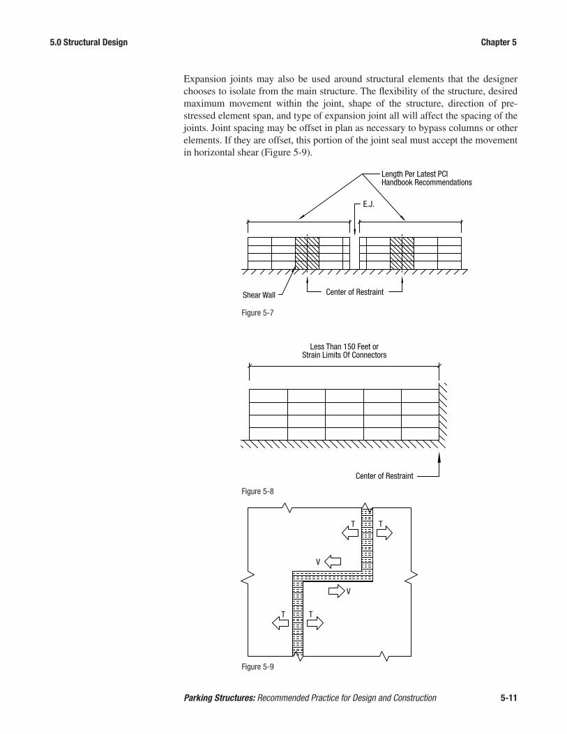
5.0 Structural Design Chapter 5
Parking Structures: Recommended Practice for Design and Construction 5-11
Expansion joints may also be used around structural elements that the designer chooses to isolate from the main structure. The flexibility of the structure, desired maximum movement within the joint, shape of the structure, direction of pre-stressed element span, and type of expansion joint all will affect the spacing of the joints. Joint spacing may be offset in plan as necessary to bypass columns or other elements. If they are offset, this portion of the joint seal must accept the movement in horizontal shear (Figure 5-9).
Figure 5-7
Figure 5-8
Figure 5-9
Length Per Latest PCIHandbook Recommendations
Center of RestraintShear Wall
E.J.
Less Than 150 Feet orStrain Limits Of Connectors
Center of Restraint
T T
V
V
T T

5.0 Structural Design Chapter 5
Parking Structures: Recommended Practice for Design and Construction 5-12
Forces due to volume change restraint in one- and two-story structures is greater than that in taller structures. Therefore, one- or two-story structures will likely re-quire more closely spaced expansion joints.
Expansion joints should be placed at high points of the drainage system wherever possible (Figure 5-10). Positioning of expansion joints should be avoided along low points or where ponding may occur.
5.4.4.1 Framing at Expansion Joints The structure must accommodate
significant movement at an expan-sion joint location. Two methods are used to separate the structure to al-low such movement; double column or slide bearing.
The ideal structural approach to ex-pansion joints is the double column (Figure 5-11). The double column joint may increase the initial proj-ect cost relative to other approaches, but it truly allows the building to be separated into independent sections without relying upon the adjacent structure for support. In addition, the solution offers simplified construc-tion and maintenance.
The sliding joint (Figure 5-12) de-pends on a slide bearing mechanism to ensure freedom of movement. The proper functioning of slide bearings depends on proper design, detailing,
Drai
ns a
tLo
w P
oint
Exp
JT a
tHi
gh P
oint
Drai
ns a
tLo
w P
oint
Figure 5-10 E.J.
Double Column Expansion Joint
E.J.
Sliding Expansion Joint
Figure 5-11
Figure 5-12

5.0 Structural Design Chapter 5
Parking Structures: Recommended Practice for Design and Construction 5-13
accurate installation, and continued maintenance. Care must be taken to properly align the slide bearings so that they operate correctly.
These slide bearing connections consist of low-friction material such as Teflon bonded to neoprene or neoprene-impregnated layered fabric, as well as a polished stainless steel plate oversized to accommodate the anticipated movement and toler-ances, attached to the top structural member. These allow movement in the direction intended (Figure 5-13). In the design of these bearings, the designer must consider the bearing stresses for the case where the bearing area would be minimized in the expansion-contraction cycle.
5.4.4.2 Expansion Joint Details The most common expansion joint system used in parking structures for vehicular
traffic is the multi-cell gland with ambient cured nosing (Figure 5-14). The multi-cell gland is comprised of an extruded thermoplastic rubber. The shape of the seal allows for a range of thermal movement while remaining water tight. The nosing material is a two-component compound comprised of elastomeric urethane resin and sand. This system is specifically suited for normal vehicular traffic. There are several manufacturers that offer various varieties of this system.
Horizontal MovementBearing Pad Length Bearing Plate In
Upper Structural Member
10 Gauge (Min.) PolishedStainless Steel Plate Fastened ToUpper Structural Element w/2B Polished Surface (Min.)Facing PTFE
Reinforced Bearing PadFastened To LowerStructural Element
PTFE Bonded ToBearing Pad
Bearing Plate in Lower Structural Member
PTFE = Polytetrafluorethylene
Figure 5-13
Expansion Joint System,Elastomeric Membrane WithAmbient Cured Urethane Nosing
Figure 5-14

5.0 Structural Design Chapter 5
Parking Structures: Recommended Practice for Design and Construction 5-14
For heavier loading conditions such as bus or service vehicle traffic, a higher capac-ity joint system is available (Figure 5-15). This system features a similar multi-cell gland adhered to the blockout. The nosing material in this system is a highly dura-ble steel reinforced rubber panel bolted rigidly to the substrate. The seal provides similar movement capacity and watertightness to be successfully used in exposed conditions. The system may be used for any vehicle expansion joint condition, but at a much higher cost. For this reason, reinforced bolt-down expansion joints are typically used only in extreme loading conditions. Consideration should be given to appropriate design of the bolt embedment capacity including possible capacity reduction due to edge distance.
Other types of expansion joints are used in pedestrian conditions such as isolation of stair and elevator towers from the parking structure. The multi-cell gland is ad-hered to the sides of the joint opening (Figure 5-16). After the gland is installed, air is pumped into the cells to force the glands into a state of compression, further ensuring a water-tight and durable seal. Another type of pedestrian-grade seal is the preformed expanding foam (Figure 5-17). The material is micro-cell self-expand-ing foam impregnated with an acrylic polymer. The gland is pre-compressed and installed into the joint with an epoxy adhesive. This type of joint is available in a variety of colors allowing it to blend in architecturally with surrounding materials. The system can be used in vertical applications as well.
Expansion joint design must also consider the movement of wheel loads from one side to the other. Vehicles in the drive lanes cause deflections. As a vehicle moves across an expansion joint, the wheel load moves from a deflected tee to one that is not yet deflected. This can cause an uncomfortable bump and premature wear on the joint seal, which could result in water leakage. The structural detail should provide for the vertical transfer of loads so that these surfaces remain aligned verti-cally while permitting horizontal movements. This is discussed in 6.11 and is often accomplished with pairs of offset plate, angles or channels, each of which is con-nected to only one side of the joint.
Metal ReinforcedRubber Anchor Block
SealantExtruded
ThermoplasticGland
Figure 5-15

5.0 Structural Design Chapter 5
Parking Structures: Recommended Practice for Design and Construction 5-15
5.5 Considerations for Fire Many precast parking decks will be required to meet some level of fire endurance.
The exception will be those that are sufficiently open and classified by the design professional as Type II-B construction. Open parking structures of Type I and Type II-A construction and those classified as enclosed parking structures will be re-quired to meet code-prescribed fire ratings. Enclosed parking structures must be equipped with an automatic sprinkler system. Mixed use parking decks with retail or other occupied space may be required to meet a higher level of fire endurance if the precast structure is used for fire separation between occupancies.
The IBC does not require the floor joints or openings of the parking levels to be fire protected. Floor joints do not need to be fire protected because the ramps and wall openings prevent the build-up of hot gasses as would otherwise occur in a confined space. As a result of this exemption, many designers and fire marshals have also excluded the requirement of minimum thickness for heat transmission through the deck surface. A code change has been accepted into IBC 2015 that specifically exempts parking garage floors from the minimum thickness for heat transmission.
Figure 5-16
Elastoprene RubberWaterproofing Seal
High StrengthEpoxy Adhesive
(Both Sides)
Figure 5-17
Factory AppliedSilicone Face Seal
Epoxy Adhesive
Self-ExpandingMicro-Cell Foam

5.0 Structural Design Chapter 5
Parking Structures: Recommended Practice for Design and Construction 5-16
This does not exclude the requirement for the deck to support realistic loads for the specified fire duration. In a double tee deck, for example, the double tee should be analyzed to ensure that the member will not fail due to gravity load for the specified fire duration. The flange reinforcing should also be checked to verify that it will likewise comply. This can be achieved by method of rational design, or by a pre-scriptive method regarding the restraint offered by the structure and minimum con-crete cover for the reinforcing, as illustrated in the PCI Handbook. The IBC exemp-tion does not apply, however, to mixed use structures in which the floor becomes a fire barrier separating a parking level from areas intended for other occupancies. In mixed use structures, full measures for fire protection of the structure in addition to allowance for firefighting equipment loads must be taken.
5.6 Structural Components There is a wide variety of products, finishes, reveals, colors and textures that are
available for use in precast concrete. Many options may be accommodated based on the member types, sizes and availability. The following is a review of details and characteristics of precast concrete products to be considered when they are incorpo-rated in a parking structure.
Most structural elements used in precast concrete parking structures are prestressed members. Adequate strength for specified loads and code prescribed load combi-nations is assumed. Control of stresses is a consideration for parking structures exposed to either coastal salt spray or deicing salts. In these more severe environ-ments, critical stresses may be limited to avoid cracking under realistic live loads as discussed in Section 5.2.2.
5.6.1 Stemmed Floor Members The most common floor deck members used in precast parking structure construc-
tion are double tees. Double tees can clear span bays that incorporate a standard parking module that consists of a drive aisle and two rows of parking, thus provid-ing unobstructed, column free space. Double tees can be provided as field-topped or pretopped. Pretopped is the term applied to double tees with flange thickness and top surface finish of the completed floor and is not intended to imply a two-stage manufacturing process where the slab is completed with a secondary casting in the plant.
Field-topped double tees are produced with a thinner flange section that will receive a cast-in-place (CIP) composite topping (Figure 5-18). This topping is considered to act as an integral structural unit with the tee section, and the surface of the tee should be finished in such a way that composite action is easily achieved. One ben-efit of field-topped double tees is that the joints between precast members are not openly exposed, but instead the composite topping is provided with tooled joints to match the precast layout below the topping. Using this system may assist in differential cambers and drainage. One point to note is that if an area of the deck is required to have a waterproofing membrane, it cannot be placed between the precast and composite topping. This would interfere with the structural performance of the system and negate the composite action.

5.0 Structural Design Chapter 5
Parking Structures: Recommended Practice for Design and Construction 5-17
Pretopped double tees can be a viable alternative to field-topped concrete (Figure 5-19). Among the advantages of this structural system is that it produces an excel-lent high strength plant-produced wearing surface instead of a lower strength, field-topped surface. In some areas, it is possible to achieve even more durable strengths of 6000-8000 psi. The top flange surface is typically provided with a light broom finish to improve traction. With this system, special considerations are critical for adjacent camber differential, joint treatments, and drainage. Also note that field-top-ping may still occur at the ends of pretopped double tee systems for connections and diaphragm chord reinforcement.
There are differing practices and views relative to durability of field-topped versus pretopped double tees. Users of this manual are advised to study local practices and the durability aspects of both concepts. Durability is covered in Chapter 3.
Double tee width has continued to evolve over the years. The most commonly sup-plied double tee at this time is 12 ft wide. There have been applications where 15 ft wide double tees have been successfully used. There has been a discussion of further extending the width to 16 ft. For applications with double tee widths greater than 12 ft, due consideration should be given to hauling limitations and the possibil-ity of hauling the product on a special frame in a tilted position.
Single tees have been used for floor elements in the past. Because of the inherent handling instability of single tees and the increased efficiency in the production of double tees, their use is typically isolated to unusual conditions or where use of double tees cannot be dimensionally accommodated.
Mesh and/or RebarIn CIP Composite Topping
Reinforcement InPrecast Tee
Figure 5-18
Mesh and/or RebarDesigned for + and -Moments
Provide ProperClear Cover
Figure 5-19

5.0 Structural Design Chapter 5
Parking Structures: Recommended Practice for Design and Construction 5-18
It is possible to have a struc-tural system which consists of a precast concrete stem and a cast-in-place deck (Figure 5-20). Such sys-tems do not have the speed of construction or initial cost effectiveness of a total-ly precast concrete system, as it requires field placed forms and cast-in-place deck. The system may in some situations be a viable alter-native as it offers wider stem spacing and the possibility of transverse post-tension-ing.
Whether field-topped or pretopped, there are a number of structural design consid-erations common to double tees.
1. The bearing area of double tees typically should be reinforced with properly anchored bearing plates. The length of bearing over a support as erected is com-monly 4-5 in. However, other bearing lengths have been used successfully as long as careful consideration is given to production and erection tolerances and anticipation of long-term movements while designing and detailing bearings.
2. The precast flange and composite topping will be subjected to the code-specified concentrated loads. The cast-in-place topping reinforcement will contribute to the resistance for these loads.
For double tee structures, the flange must be checked for flexure and shear that is perpendicular to the span of the double tee. This analysis includes consider-ing the flange plus any composite topping as a continuous span between stems. Outside the stem, the flange may be considered as a propped cantilever or as a cantilever, depending on the spacing and stiffness of the flange connections. The consideration of the slab as a cantilever outside the stem is based on the assump-tion that a through crack at the joint between double tees may occur, and that this crack could interrupt the slab continuity provided by the structural topping. For structures utilizing pretopped double tees, this slab might be considered to be a propped cantilever if there is sufficiently close spacing of the flange connections. Since the flange reinforcement is typically greater transverse to the stems, and the spacing of flange connections may be variable, the accurate determination of the design section for concentrated loads is complex. Experimental studies10 have shown actual flange strength is greater than predicted by traditional contrib-utory length assumptions or yield line analysis. Crack patterns suggest that the contributory length is more accurately predicted by an oblique angle as shown in Figure 5-21. When this length of flange is considered, even the wide spacing of connections near the ends of the tees falls within the influenced area.
The area of the flange most vulnerable to concentrated loading is at the corners. In those areas, the chord reinforcing and added handling trim steel at the ends of the flange add to overall strength for pretopped double tees with or without pour
Figure 5-20
CIP Structural Slab
Precast Joists

5.0 Structural Design Chapter 5
Parking Structures: Recommended Practice for Design and Construction 5-19
strips and for topped double tees. Reinforcement should be checked for resis-tance to corner breaks.
3. Longitudinal cracking at the juncture of stem and flange sometimes occurs. When this crack occurs on the inside of the section between the stems, it is usu-ally the result of wracking during stripping, handling, shipping, or due to exces-sive warping of the floor for drainage. If there is a warping crack at one end of the double tee, it is likely that another will be found at the opposite end of the double tee inside the other stem. Although associated with twisting or torsion in the member, these cracks are actually local bending in the flange across the stems at the ends. The history of topped precast parking structures indicates that such cracking will not deteriorate with time and will not affect the long term perfor-mance of the double tee. If the crack extends through the flange in a pretopped member, it should be evaluated and treated with joint sealant or other means only if necessary to prevent excessive moisture ingress.
Figure 5-21
13
b
Trib
utar
yLe
ngth
3000
lbPo
int
Load
3000 lb LoadDistributed EquallyAcross Joint
Flange Connections
Mesh and/or RebarDesigned for + and -Moments
P/2 P/2
Clear Cover PerACI Committee 362

5.0 Structural Design Chapter 5
Parking Structures: Recommended Practice for Design and Construction 5-20
4. Flange connectors should be investigated for strength under the application of a wheel load at the connector. Flange connectors should be spaced approximately 8 to 10 ft apart for the full length of the member when field-topping is used. For pretopped floor members, spacing should be 4 to 6 ft apart in a drive aisle, but may be spaced more widely at parking stalls or near the ends of double tees where differential movement between adjacent members from moving loads is less. Diaphragm forces may require smaller spacing.
5. Control joints must be provided in the structural topping in vertical alignment with the double tee flange joints and these joints must be sealed. If not sealed, these cracks may allow leaks and cause deterioration. Commonly, a tooled joint filled with a flexible sealant has been used effectively to prevent leakage and deicing salt-related deterioration (Figure 5-22). See Chapter 3 for additional in-formation.
6. The bearing of stemmed members should not be welded to their supports. Con-nections to support members should be made at the flanges of stemmed members (Figure 5-23). This is needed to allow the bottom of the stemmed members to deform due to volume change effects.
CIP Topping
Tee Flange
HandTooledJoint
No Connection
Figure 5-22
Figure 5-23

5.0 Structural Design Chapter 5
Parking Structures: Recommended Practice for Design and Construction 5-21
7. Double tees are commonly dapped at supports for vertical clearance. Dapped double tees are particularly sensitive to cracking in the region of the support, if not properly reinforced. The PCI Design Handbook and reference 11 are recom-mended to the designer for reference. Limits on the dap depth and reinforcing steel detailing are critical for proper performance of these end regions. Reinforc-ing steel at the bearing region should be provided to transfer the applied loads from the full-depth section to the reduced-depth section (Figure 5-24). Addition-al research is currently being undertaken through a PCI specially funded project. Its results should simplify the reinforcement details at dapped ends.
8. Differential camber between adjacent pretopped double tees must be controlled to create a reasonably smooth driving and walking surface. This can be accom-plished by minimizing the prestress force in design, proper storage in the yard, and, most importantly, by field adjustments using jacking and shimming proce-dures. A maximum 1⁄4 in. differential camber is permitted in the driving lane area which occurs near midspan. Various methods to alleviate differential camber are available to erectors. Vertical alignment measures should be taken before joint connections at the midspan are made. A maximum of 3⁄4 in. differential for field-topped double tees is generally tolerable at the ends of the span. For more infor-mation on standard tolerances refer to PCI MNL-13512.
Figure 5-24
1½" maximum
Vua + Nu(h-d)
Nu
Av
h
Vu
a
H-d
Ash
A'sh
AhAs
Center of gravity of flexurereinforcement
Critical, minimize
d maximum2 3
d
DH
Critical, minimize
Critical, minimize
Note: Flexure and shear reinforcement omitted for clarity.
H-D
H-D
DH
A'sh
Ash

5.0 Structural Design Chapter 5
Parking Structures: Recommended Practice for Design and Construction 5-22
5.6.2 Hollow Core and Flat Slabs These products do not offer the same clear span length as other options, but may be
used in smaller areas requiring more headroom. Hollow core slabs have voids that are susceptible to water intrusion and freezing and may be fabricated with multiple layers of concrete that makes them unsuitable for most parking garage applications in environments subjected to freezing and thawing cycles. Hollow core products should only be used with caution and with specific attention to location and details for protection. Flat slabs are recommended for most parking garage applications. A structural composite topping may also be used with flat slabs or hollow core.
5.6.3 Composite Topping for Stemmed and Slab Floor Members The thickness of structural concrete topping should be no less than 2 inches at all
locations, including the midspan of cambered tees provided appropriate concrete cover is achieved with the type of topping reinforcement used. Where deicing chemicals are commonly used, the thickness should be no less than 3 in. at supports to ensure ample cover. Non-composite topping acting as a diaphragm to resist earth-quake forces must be at least 2 ½ in. thick. Topping thickness also may be governed by fire ratings, floor diaphragm stresses, or flexure under large concentrated loads (e.g., fire trucks).
The topping design thickness must be considered when reinforcing bars are to be placed in the topping, such as when required for continuity or connections. All re-inforcement provided in the cast-in-place topping should meet required lap length in accordance with ACI 318.
ACI 318 discusses horizontal shear strength between composite topping and precast members. The topping and precast interface must be continuous. As previously stat-ed, any interruptions due to water-proofing or other type of membrane will render the topping as non-composite.
5.6.4 Beams and Spandrels Interior inverted tee beams and exterior spandrels are the primary supporting mem-
bers for the parking structure deck. Exterior spandrels may be provided with an architectural finish on the outside surface, but are generally heavily reinforced and considered to be structural members subject to the tolerance requirements of PCI Manual 11613.
There are a number of structural design considerations for beams and spandrels.
1. The bearing area of beams should be reinforced with properly developed bars.
2. A structural topping may be used as a composite compression flange for beam design. The requirements of ACI 318 may be used to determine the effective flange width. When the topping or pour strip over the beam is crowned for drain-age, the width of the effective flange should be based on the average thickness over the adjacent double tees. The flange of the double tee should not be included in the beam flange thickness because joints between double tees interrupt the continuity of the compression block. Tooled joints in the topping must be con-sidered when sizing transverse reinforcement in the topping across the top of the

5.0 Structural Design Chapter 5
Parking Structures: Recommended Practice for Design and Construction 5-23
beam. The reinforcing should be sufficient to mobilize the compression in the topping over the double tee flanges by shear friction.
3. Inverted tee beams may be loaded from one side only during erection (Figure 5-25). This temporary torsion needs to be considered in the beam design. Erec-tion connections, or shoring, should be provided to control beam rotation.
4. Providing a lateral support near mid-depth of a member, such as a spandrel to the diaphragm, will provide the lateral support required to satisfy ACI 318.
5. Ledges for spandrel beams should be designed in accordance with the latest rec-ommendations of the PCI Design Handbook. Designers should be aware of PCI Technical Bulletin 12-00114. Caution is warranted for heavily loaded ledges.
6. Spandrels with aspect ratios greater than 4.5 subject to eccentric gravity loads do not exhibit classical torsion behavior. The failure mechanism is primarily out-of-plane bending and closed transverse reinforcement is not required. Design for eccentric loads may be done in accordance with the recommendations provided by Lucier, et al15. It is advisable to prestress pocketed spandrels to prevent cracks around pockets due to deep beam non-linear action.
Tees on thisBay Not Yet
Erected
Figure 5-25

5.0 Structural Design Chapter 5
Parking Structures: Recommended Practice for Design and Construction 5-24
5.6.5 Columns Columns may be used in both the
exterior and interior of a parking deck to provide support for hori-zontal framing members. Columns may be pocketed to provide bear-ing for spandrels, depending on the architectural features that may be required for the project. While it is preferable that beams align with the column centerline, this often is not architecturally desirable at the exte-rior. Eccentric loading on columns resulting from offsetting spandrel beams will result in column bending (Figure 5-26). When the spandrel beam is in a notch on the outside of the column, the global eccentricity is less because the center of reaction from the double tee stems is closer to the center of the column. When the spandrel beam is in a notch on the inside of the column, the glob-al eccentricity and the applied mo-ment is greater.
5.6.6 Wall Panels Wall panels may be included in the structural framing as interior ramp walls, exte-
rior load bearing or nonbearing walls, or shear walls. The walls may be provided with architectural finishes. Reference should be the Manual for Quality Control for Plants and Production of Precast and Prestressed Concrete Products (MNL-116).
Walls most commonly are provided as multi-story vertical elements, but single story horizontal walls may be appropriate in certain situations to satisfy structural demands or to simplify erection. Walls are generally spliced above a floor line to provide better access to the joint and the connections.
In some cases, the foundation-to-floor or floor-to-floor height may exceed the ship-ping width of a horizontal wall panel and require horizontal joints between lateral supports. Some configurations may result in a mechanism that is not stable if the joints are considered pinned. These conditions require the development of sufficient out-of-plane moment capacity in the joints to ensure stability.
5.6.7 Stair/Elevator Cores An early decision in the planning process for the structural framing is whether the
stair and elevator cores will be isolated from or integral with the main structure. This decision is based on the locations of the cores and the resulting influence on accommodating volume changes and the demands for lateral stability of the struc-ture where the cores may have to contribute lateral strength and stiffness. The deci-
Note:Connections NotShown for Clarity
M
e
Figure 5-26

5.0 Structural Design Chapter 5
Parking Structures: Recommended Practice for Design and Construction 5-25
sion affects the arrangement of framing elements, the detailing of connections, and non-structural detailing for durability.
Framing of stair and elevator cores may include walls, beams, columns, and stair riser units. The precast stair riser units can expedite erection, minimize coordination with other trades and provide better durability in climates where salt is a concern. Anchorages for elevator hardware, windows, railings and similar items should be coordinated with the precast supplier during the shop drawing phase.
5.7 Lateral Force-Resisting Systems Lateral force resisting systems are considered as the combination of vertical compo-
nents and the horizontal diaphragms that distribute the loads to those vertical com-ponents. Typical lateral force-resisting systems in the precast, prestressed concrete industry are floor diaphragms, shear walls, and frames such as moment frames or truss action frames.
5.7.1 Floor Diaphragms The floors of a parking structure must serve as a diaphragm to create a structure
that will be stable when subject to lateral loads. A diaphragm is a critical link in the load path for resistance of lateral loads. A diaphragm is required to accept lateral loads from other elements, have the strength and stiffness to provide resistance to those loads, and distribute the lateral loads to the vertical systems that carry loads to the foundation. As opposed to simple, planar diaphragms in many building types, the load path through a diaphragm in a parking structure is more complex because ramping generally disconnects the bays in each floor.
The primary references for design and detailing of diaphragms are the PCI Design Handbook, Seismic Design of Precast/Prestressed Concrete Structures, and the Di-aphragm Seismic Design Methodology (DSDM) research report16.
In areas where seismic loads do not govern the design of the lateral force resist-ing system, relatively simple assumptions can be made in designing diaphragms. It might generally be assumed that the diaphragms are rigid so that forces can be distributed according to the relative stiffnesses of the vertical bracing elements. Strength can be provided using a simple horizontal beam analogy where flexural strength is provided by chord reinforcement or connections and shear strength is provided by connections along joints between members.
In seismic regions, the level of analysis and design complexity will depend on the Seismic Design Category (SDC) defined by the general building code for the loca-tion of the project. Generally, a fundamental philosophy is that inelastic action and energy dissipation should occur in the vertical lateral resisting systems. The dia-phragm design and detailing must allow that to happen. Considerations may include some or all of the following:
• Rigid versus flexible diaphragm behavior• Level of inelastic behavior to be allowed in diaphragm• Deformation characteristics required in connections• Interaction of shear and tension in connections

5.0 Structural Design Chapter 5
Parking Structures: Recommended Practice for Design and Construction 5-26
• Flow of forces into the vertical bracing elements• Diaphragm displacements
When the floors are constructed with a cast-in-place structural topping, the dia-phragm strength may be provided in the topping alone or as a composite system with the precast elements. Topping reinforcement is generally sized to provide required strength across joints between precast members. The minimum topping thickness may be dictated by the size of reinforcement required. It is still recommended that a minimum level of connection detailing be provided between the precast members for leveling and temporary bracing during erection.
There will be a tendency to develop strong, rigid connections in a diaphragm de-sign. The everyday performance of the structure is still paramount. Strong, rigid connections tend to restrain volume change displacements generating forces and undesirable cracking. A balance is required between connection performance re-quired for resistance of lateral loads and deformation capability for relief of volume change strains.
5.7.2 Shear Walls Shear walls are the most common lateral force resisting system used in precast
concrete parking structure construction. The reasons include simple connections, reliable performance and reasonable economics. Shear walls may be provided with openings to improve visibility and security for users.
Shear walls are designed as cantilevers from the foundation. As such, they are rigid for the in-plane direction and flexible for out-of-plane movement. These character-istics influence decisions on shear wall locations to control development of restraint to volume change movements. It is desirable to locate shear walls close to the center of rigidity for their in-plane direction and may be located farther from the center of rigidity for their out-of-plane direction. It is also desirable to use shear walls as load bearing elements. The additional gravity load reduces the uplift demand on base connections.
In seismic regions, shear walls may have to provide energy dissipation through inelastic behavior. Techniques are available to emulate cast-in-place concrete or to use connections that provide energy dissipation. Testing has shown precast concrete shear walls with vertical post-tensioning have excellent performance characteris-tics for seismic regions. Vertical post-tensioning reduces wall drift and creates a system that is self-centering after an earthquake event. The primary references for shear wall design are the PCI Design Handbook and Seismic Design of Precast/Prestressed Concrete Structures.
5.7.3 Moment Resisting Frames When functional design dictates that shear walls cannot be used, moment resist-
ing precast concrete frames can be provided for lateral load resistance. To create frames, precast elements may be cast with integral beam column joints to create frames from simple horizontal and vertical elements. In addition, bracing elements of various configurations may be used in some of the bays. The technology is avail-able to emulate cast-in-place frames or to provide more innovative seismic resisting

5.0 Structural Design Chapter 5
Parking Structures: Recommended Practice for Design and Construction 5-27
frames such as the hybrid frame17. To manage the economics of a rigid frame sys-tem, only the number of frames required to provide adequate strength and stiffness should be used.
In the design of moment resisting frames, the resistance to lateral loads is the prima-ry focus. However, moment resisting frames inherently provide restraint to volume change movements. A load case including volume change should be investigated to assure satisfactory performance for the durability demands of the structure.
The primary references for frame design are the PCI Design Handbook, Seismic Design of Precast/Prestressed Concrete Structures, Emulating Cast-in-Place De-tailing in Precast Concrete Structures (ACI 550.1)18, and Design Guide for Connec-tions in Precast Jointed Systems (ACI 550.2)19. These references provide direction for non-seismic frames as well as extensive coverage of the different types of seis-mic resisting frames.
5.7.4 Ramp Truss Action In a continuously ramped structure, lateral resistance might be achieved by using
the ramp as a truss member, with the floors acting as web members and the columns acting as chord members. Using the ramp floor as a diagonal brace constitutes a reinforced concrete braced frame. Proper detailing is essential to transferring loads through the load path. When this approach can be used, web members should be connected at the lowest extremity of the structure. Special consideration should be given to the chord members and also to force reversals within the load path.
References:
1. American Concrete Institute. 2011. Building Code Requirements for Structural Concrete (ACI 318–11) and Commentary (ACI 318R–11). Farmington Hills, MI.
2. Precast/Prestressed Concrete Institute. 2010. PCI Design Handbook: Precast and Prestressed Concrete. (MNL-120-10). 7th Edition, Chicago, IL.
3. American Society of Civil Engineers (ASCE). 2010. Minimum Design Loads for Buildings and Other Structures. (ASCE/SEI 7-10) Reston, VA.
4. International Code Council. 2012. International Building Code. (IBC) Country Club Hills, IL.
5. Parking Consultants Council, National Parking Association. 1987. Recommend-ed Building Code Provisions for Open Parking Facilities. Washington DC.
6. Iqbal, M. 2008. Designing Edge Barriers in Parking Structures. Structure Mag-azine. October: pp. 24-26.
7. Denver Building Code. 2012. 2011 Denver Amendments to the 2009 Interna-tional Codes. Section 1607.14. City of Denver, Denver, CO.

5.0 Structural Design Chapter 5
Parking Structures: Recommended Practice for Design and Construction 5-28
8. Cleland, N., Ghosh, S.K. 2012. Seismic Design of Precast/Prestressed Concrete Structures. (PCI MNL 140-12) Chicago, IL.
9. Klein, G., Lindenberg, R. 2009. Volume-Change Response of Precast Concrete Buildings. PCI Journal. V. 54, No. 4 (Fall): pp. 112-131.
10 Steele, S. 2006. Point Load Tests and Flange Reinforcement in Double Tees. Pennsylvania State University.
11. Mattock, A., Theryo, T. 1986. Strength of Precast Prestressed Concrete Mem-bers with Dapped Ends. PCI Journal. V. 31, No. 5 (September-October): pp. 58-75.
12. Precast/Prestressed Concrete Institute. 2000. Tolerance Manual for Precast and Prestressed Concrete Construction. (PCI MNL-135). Chicago, IL.
13. Precast/Prestressed Concrete Institute. 1999. Manual for Quality Control for Plants and Production of Precast and Prestressed Concrete Products. (MNL-116). Chicago, IL.
14. Precast/Prestressed Concrete Institute. 2012. Ledge Punching Shear Advisory. (Tech Bulletin 12-001). Chicago, IL.
15. Lucier, G., Rizkalla, S., Zia, P., Klein, G., Walter, C. 2011. Development of a Ra-tional Design Methodology for Precast Concrete Slender Spandrel Beams: Part 2, Analysis and Design Guidelines. PCI Journal. V. 56, No. 4 (March-April): pp. 106-133.
16. Fleischman, R.B. 2014. Seismic Design Methodology Document for Precast Concrete Diaphragms. University of Arizona.
17. Celik, O., Sritharan, S. 2004. An Evaluation of Seismic Design Guidelines Pro-posed for Precast Concrete Hybrid Frame Systems. Iowa State University.
18. ACI/ASCE Joint Committee 550. 2009. Guide to Emulating Cast-in-Place De-tailing for Seismic Design of Precast Concrete Structures (ACI 550.1). Ameri-can Concrete Institute, Farmington Hills, MI.
19. ACI/ASCE Joint Committee 550. 2013. Design Guide for Connections in Pre-cast Jointed Systems. (ACI 550.2). American Concrete Institute, Farmington Hills, MI.

6.0 Connections Chapter 6
Parking Structures: Recommended Practice for Design and Construction 6-1
6.0 CONNECTIONS 6.1 General Any precast/prestressed concrete structure can be considered the synthesis of three
primary aspects: the system, the components, and the connections. Other parts of this design guide discuss system analysis and design and component design with spe-cific consideration of the distinctive requirements of parking structures. It is import-ant to consider connections in the context of the requirements for parking structures. Connections are an essential part of the jointed precast assembly in establishing and defining the load path that links every component to the foundation.
Connection design is dealt with extensively in the PCI Design Handbook MNL 1201 and in the PCI Connection Manual 1382. Connections used in parking struc-tures have special requirements. Some of the connections used in precast concrete parking structures are subject to significant and cyclic movement. The exposed en-vironment with freezing and thawing and aggressive chemicals from deicing also must be accommodated. Connections must be detailed and installed to ensure that movements and environment are accommodated during the service life of the struc-ture. This is a particular challenge for the designer, but it can be accomplished with proper selection of the connection type and arrangement of connection components.
Connections can be grouped by their functions: gravity load path; lateral load path; or structural integrity. Although many connections share these functions, the primary function is generally evident. Connections are also distinguished as being either “dry” or “wet.” Dry connections make the links between components with bolts, welds, elastomeric pads, shims or a combination of these. These are often termed “mechani-cal” connections. Wet connections are those that use field-placed concrete or grout to complete the mechanical link with lapped, hooked or spliced reinforcement.
6.2 Continuity of Load Path Connections must establish a continuity of load path. The support of gravity loads or
the lateral forces for wind and seismic loads will govern the design of most of the con-nections, but the minimum requirements imposed for structural integrity will ensure at least a minimum provision for abnormal loads that are not included in the customary design load criteria. Every component must be connected so that gravity and lateral forces are linked to the foundation through a continuous path. In a parking structure, the gravity parts of that path may include corbels, dapped ends, horizontal wall joints, column splices, hangers, and component bearings. The first check of the adequacy of any system of connections in a parking structure is that the complete continuity of load path is provided. Each connection must be designed with sufficient strength to transfer the required design forces during the life of the structure.

6.0 Connections Chapter 6
Parking Structures: Recommended Practice for Design and Construction 6-2
6.3 Ductility Ductility is defined as the ability of an element to continue to sustain load and
deformation after initial yielding. The open and unheated environment of parking structures subjects the structure to movements that must be accommodated, but for connections the requirement for ductility is much more than accommodation of vol-ume change movement. Connections may experience local overloads, but this must not be permitted to result in sudden and catastrophic failures. Ductility is related to yield deformations and the absence of brittle failure modes controlling the limit to strength. One strategy for connection design often employed is to design with suf-ficient overstrength to ensure that the connection remains elastic under all possible load or deformation effect, but provisions in ACI 3183 for anchorage to concrete have become so conservative that such design without supplementary reinforce-ment is often impractical. Ductile connection strength must be controlled by steel yielding, and that strength must be sustained through the total amount of deforma-tion that the connection might be expected to experience. Ductility requirements are more pronounced in connections resisting seismic loads.
6.4 Gravity Connections Gravity load connections should be the most direct and simple connection designs
in a precast concrete parking structure. Many of these connections provide no more than bearing of concrete, but concrete-to-concrete contact in bearing is not an ac-ceptable condition in a parking garage. Production and erection tolerances and movement due to volume changes require some spacer between concrete surfaces to even the stresses of less than perfect planes, and supplemental reinforcement near those bearing surfaces to prevent crushing or spalls at the component edges. There is a natural reluctance for precast manufacturers to provide exposed steel plates for bearing because the environment of parking structures requires that all exposed steel be protected from corrosion by galvanizing, electroplating or the use of stain-less steel. On the other hand, some sensitive conditions benefit significantly from the armoring of bearing surfaces provided by plates. Double tee stem bearings are almost always armored with steel bearing plates whether the bearing is a plain end or a dapped end where the plate also provides some anchorage for reinforcement. To avoid exposed finished hardware in wider bearing surfaces, reinforcement assem-blies can be welded together and bolted to the forms.
In many parking garages, spandrel beams are provided gravity load support on col-umns with let-ins or block-outs that fit the profile of the beam. These beams rest on elastomeric bearing pads, but require additional support to take eccentric grav-ity loading from the beam to the column. The torsion connections are commonly placed near the top and bottom of the beam using rods that project through sleeves in the column. It must be recognized that these rod connections also provide a load path that braces the column through the spandrel beam connection to the floor dia-phragm. This secondary load path can add to the loading of the tie rods and must be considered in the overall design of the structure.
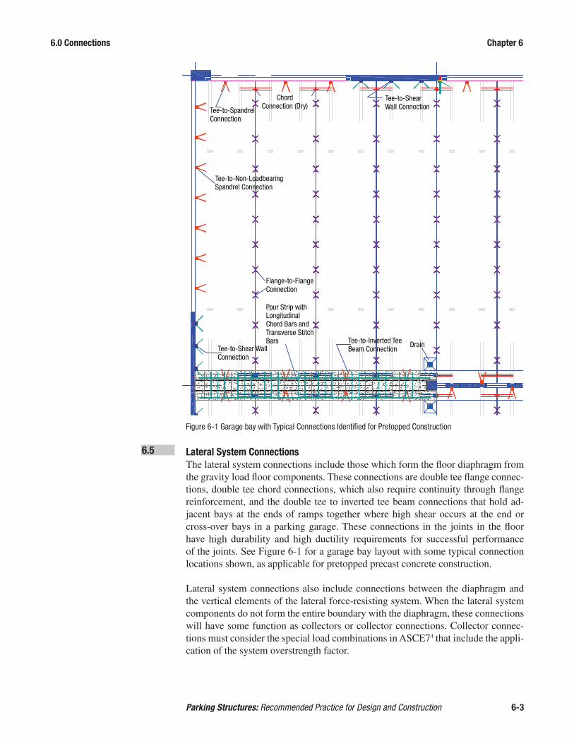
6.0 Connections Chapter 6
Parking Structures: Recommended Practice for Design and Construction 6-3
6.5 Lateral System Connections The lateral system connections include those which form the floor diaphragm from
the gravity load floor components. These connections are double tee flange connec-tions, double tee chord connections, which also require continuity through flange reinforcement, and the double tee to inverted tee beam connections that hold ad-jacent bays at the ends of ramps together where high shear occurs at the end or cross-over bays in a parking garage. These connections in the joints in the floor have high durability and high ductility requirements for successful performance of the joints. See Figure 6-1 for a garage bay layout with some typical connection locations shown, as applicable for pretopped precast concrete construction.
Lateral system connections also include connections between the diaphragm and the vertical elements of the lateral force-resisting system. When the lateral system components do not form the entire boundary with the diaphragm, these connections will have some function as collectors or collector connections. Collector connec-tions must consider the special load combinations in ASCE74 that include the appli-cation of the system overstrength factor.
Tee-to-SpandrelConnection
Chord Connection (Dry)
Tee-to-Shear Wall Connection
Tee-to-Non-Loadbearing Spandrel Connection
Tee-to-Shear Wall Connection
Pour Strip with Longitudinal Chord Bars and Transverse Stitch Bars
Flange-to-Flange Connection
Tee-to-Inverted Tee Beam Connection
Drain
Figure 6-1 Garage bay with Typical Connections Identified for Pretopped Construction

6.0 Connections Chapter 6
Parking Structures: Recommended Practice for Design and Construction 6-4
Lateral system connections may be connections which complete the assembly of the vertical elements of the lateral force-resisting system. These connections must be proportioned to transmit the required forces required by design, but there may also be additional detailing requirements that depend on the system selected and on the seismic design category, discussed below. These may be connections between beams and columns in moment resisting frames, connections in horizontal joints between walls, and connections in vertical joints between walls.
6.6 Seismic Design Considerations Connection designs for precast concrete structures assigned to Seismic Design Cat-
egories C, D, E, and F must consider the system detailing requirements for the seismic systems permitted in those categories.
Precast walls in structures assigned to SDC C must be at least intermediate precast concrete walls. This system requires that the connections between components or between the walls and the foundation must be either a Type 2 splice or must be lim-ited by steel yielding. The International Building Code (IBC)5 has adopted addition-al requirements from Chapter 14 of ASCE 7 that the connection maintain at least 80% of its design strength through the full design displacement of the wall. That means that the connection must have deformation capacity for movement in the joints being connected through the amplified lateral drift of the wall. Walls assigned to SDC D, E or F must be special structural walls, and the mechanical connections of those walls must also meet the requirements for intermediate wall connections.
Moment-resisting frames in SDC C must emulate the detailing and performance of monolithic cast-in-place intermediate frames. Moment-resisting frames in SDC D, E or F must emulate the detailing and performance of monolithic cast-in-place special frames. Typically mechanical connections placed at the face of the column where yielding is intended will not satisfy these requirements. ACI 318 makes pro-visions for strong and ductile connections for precast frames intended to emulate the monolithic cast-in-place systems. Figure 6-2 shows a frame composed of pre-cast beam and column elements cast as combined components with type 2 splices in the columns at mid-height of a level.
6.7 Structural Integrity Connections To ensure a minimum level of connectivity and redundancy in the system, ASCE
7-10 imposes requirements for connections that are not based on specific loads, but are based on member weights and assembly. For example, spandrel beams connect-ed to columns may be well balanced and not produce a positive requirement from forces parallel with the beams. ASCE 7-10, however, prescribes that the beams must be connected to the columns in their longitudinal direction for a force of at least 5% of the gravity load dead and live reaction at the column. As an alternative, it is permissible to connect the spandrel beam to the floor diaphragm for this force so long as the floor is connected to the column to transmit the force. This requirement presents an interesting detailing challenge where the spandrel beams are framed on the inside face of the columns, effectively screening the column from the floor and making direct beam-column connection difficult from a constructability viewpoint.

6.0 Connections Chapter 6
Parking Structures: Recommended Practice for Design and Construction 6-5
The requirements for anchorage of columns and walls may also be controlled by the minimum tie provisions for these elements in chapter 16 of ACI 318-11. There are integrity requirements for the lateral support of precast walls both in ACI 318 and in ASCE 7-10, and the magnitude of forces required do not agree. The larger force will govern.
Combined Bean and Column Structural Frame
Column Splice Detail
Column Reinforcing Embed
Column Reinforcing Splice Interlock Embed
Grouted Joint
Projected Reinforcing Bar (Loose Erection)
Figure 6-2

6.0 Connections Chapter 6
Parking Structures: Recommended Practice for Design and Construction 6-6
6.8 Fabrication and Erection Considerations The following should be considered when designing connections to enable fabrica-
tion and erection to be efficient:
• Standardize connection types • Avoid reinforcement and hardware congestion• Avoid penetration of forms• Reduce post-stripping work• Consider clearances and tolerances of connection materials• Avoid non-standard product and erection tolerances• Plan for the shortest-possible crane hook-up time• Provide for field adjustments• Provide accessibility• Determine if special inspection is required per the applicable code for the ma-
terial and the welding process• Provide as direct a load path as possible for the transfer of the load
For connections that are exposed to view in the final structure. The designer should incorporate a visually pleasing final product. The designer must realize that normal allowable fabrication, erection and interfacing tolerances preclude the possibility of a perfect fit in the field.
Some connections designed and detailed for final state loading may need to be con-sidered and/ or re-evaluated/ re-designed to help stabilize the structure during erec-tion. Additional connections may be necessary to help erecting some of the precast members. When inverted tee beams are loaded with all double tees on one side of the beam, the unbalanced load can cause the beam to rotate and affect final align-ment unless provisions are made to prevent this movement.
Some permanent connections rely on grouted sleeves that are not effective until the grout has cured. Supplemental welded connections might be used to establish temporary stability so the crane can release the component before that splice cure is attained.
6.9 Connection Materials A wide variety of connection hardware and devices is used in the precast concrete
industry for connections in parking structures. Some of these are as follows:
• Headed Stud Anchors are round bars with an integral head. These are typically welded to plates to provide anchorage into concrete.
• Steel Shapes including wide flanges, structural tubes, channels, plates, and angles.• Reinforcing Bars are typically welded to steel sections to provide anchorage
into concrete.• Reinforcing Bar Couplers are typically proprietary devices for connecting re-
inforcing bars at a joint. Manufacturers of these devices can provide technical information.
• Deformed Bar Anchors are similar in configuration to deformed reinforcing bars and are welded to steel shapes to provide anchorage similar to headed stud anchors.

6.0 Connections Chapter 6
Parking Structures: Recommended Practice for Design and Construction 6-7
• Bolts and Threaded Connectors are used in many precast concrete connections. Use of ASTM A366 or A3077 bolts is typical. Use of high-strength bolts is usu-ally not required.
• Coil Rods are high strength continuously threaded rods made from high car-bon, cold rolled 1045 steel. The threads are very course to engage coil inserts made with wound wire inserts.
• Specialty Inserts are available from many manufacturers of these devices. They include standard threaded inserts, coil threaded inserts, and slotted inserts that provide for tolerances and field adjustment.
• Bearing Pads are used predominantly for structural applications to support beams, double tees, and similar components. Use of random fiber oriented bearing pads (ROF) is recommended.
• Shims can be high density plastic or steel and are often used to provide adjust-ment to align a precast concrete component for elevation or horizontal align-ment.
6.10 Galvanizing-Special Precautions As noted in Chapter 3, in regions where deicer salts or coastal airborne salt are
present, the components of exposed connections sometimes are hot-dip galvanized. In order to ensure that the strength of the elements of a connection is not reduced by embrittlement during the hot-dip galvanizing process, several precautions are recommended by the American Hot Dip Galvanizers Association8. The precautions apply to welding and the potential for embrittlement of cold-worked steel. Refer to those precautions when applying galvanizing in precast parking projects.
6.11 Expansion Joint Details Expansion joints break the continuity in the structure to allow volume change
movement without restraint. As such, they generally do not require connections, but form a component-to-component relationship as connections do. In some cas-es, there is a need to transfer transverse loads across joints with connections that permit the intended free movement in only one or two directions. A discussion of expansion joint details is provided in Section 5.4.4.
To minimize the relative movement at an isolation joint between flexible members, it is desirable to provide a vertical shear transfer connection across the joint that equalizes vertical deflection while permitting the intended expansion/contraction movement (Figure 6-3).
6.12 Common Example Connection Details The following pages include schematics of details typically used on parking
projects.
Each connection must be designed for sufficient strength and ductility, as described above. In addition, the final configurations should consider the effects of volume change, durability and, at times, fire resistance. Volume changes can cause move-ment due to creep, shrinkage, and temperature change that can cause large stresses in precast concrete components and their connections of unduly restrained. It is better to design the connection to allow some movement, which will relieve the build-up of these stresses. When the connection is exposed to weather or used in a

6.0 Connections Chapter 6
Parking Structures: Recommended Practice for Design and Construction 6-8
corrosive environment, steel elements should be adequately covered by concrete, painted, epoxy-coated, or galvanized. Stainless steel may also be used. When a structure or part of it requires a fire rating, it is also important to consider protection for the connections in the rated portion Fire resistant connections, which could jeopardize the structure’s stability if weakened by high temperatures from a fire, should be protected to the same degree as the component being connected.
The designer must select and design each connection depending on the require-ments of the particular project. It is advised that the designer check with the pro-ducers in the geographical region of the project to determine if local connection preferences exist.
High Density Plastic Slide Bearing Pad Bond Upper Pad to Tee Flange and Lower Pad to Angle
High Density Plastic Slide Bearing Pad Bond Upper Pad to Tee
Flange and Lower Pad to Angle
ExpansionJoint
MaterialPlate With Nut or Threaded
Insert
All Thread With Lock Washer
and Nut
High Density Plastic Shim With Hole
Angle With Hole and Slot
Gap
Equa
l Of
fset
Equa
l Of
fset
Figure 6-3
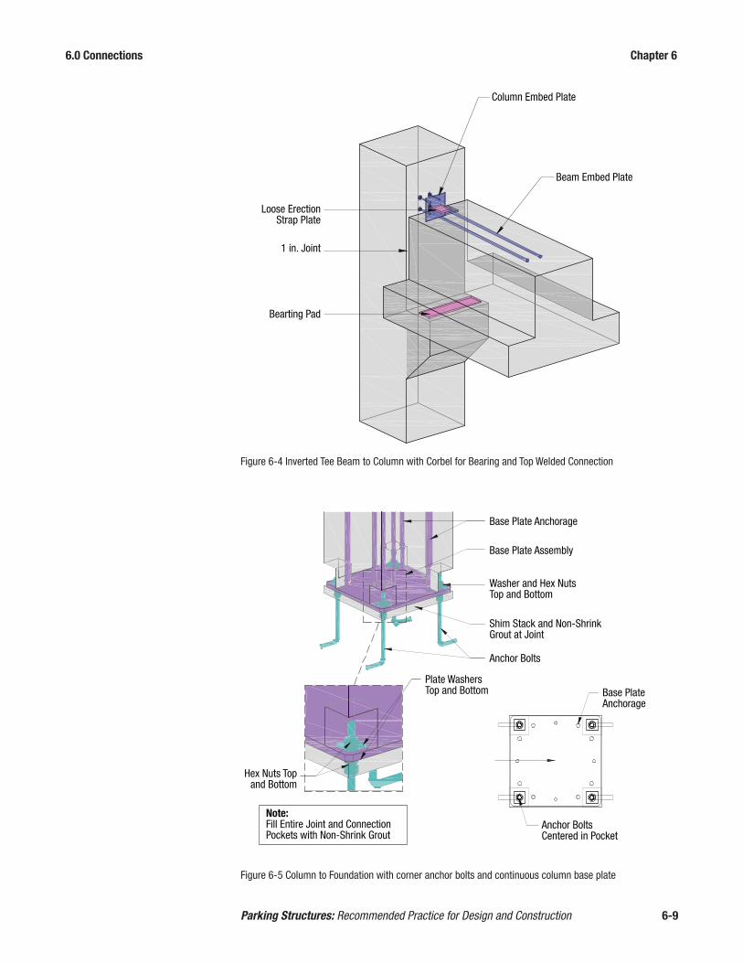
6.0 Connections Chapter 6
Parking Structures: Recommended Practice for Design and Construction 6-9
Figure 6-4 Inverted Tee Beam to Column with Corbel for Bearing and Top Welded Connection
Loose ErectionStrap Plate
Bearting Pad
1 in. Joint
Column Embed Plate
Beam Embed Plate
Weld As Required By Design
Figure 6-5 Column to Foundation with corner anchor bolts and continuous column base plate
Base Plate Anchorage
Base Plate Assembly
Washer and Hex Nuts Top and Bottom
Shim Stack and Non-Shrink Grout at Joint
Anchor Bolts
Plate WashersTop and Bottom Base Plate
Anchorage
Hex Nuts Topand Bottom
Note:Fill Entire Joint and Connection Pockets with Non-Shrink Grout
Anchor BoltsCentered in Pocket

6.0 Connections Chapter 6
Parking Structures: Recommended Practice for Design and Construction 6-10
Figure 6-6 Flange-to-Flange Relation for Sealants
Formed orGround Edge
BackerRod
Sealant
Sealant
BackerRod
BroomFinish
TooledEdge
1½ in. Min Smooth

6.0 Connections Chapter 6
Parking Structures: Recommended Practice for Design and Construction 6-11
Note 1
Continuous joint sealant recessed in. to ¼ in. Minimum depth = ½ in. for joints subjected to traffic. Proper design is 2:1 width to depth ratio
8
¼ in. radius tooled edge preferred (Ref. 2) (note 5) ¼ in. field/shop ground chamfer alternate
Note 2
Note
4
Backer Rod
Recommended DT Joint Detail Pre-Topped System
DT Flange
Notes:1. Minimum joint width = ¼ in. Maximum joint width = 1½ in.2. ¼ in. (+ ½ in., -0 in.) Joint between DT flanges typical. in. (+ ½ in., -0 in.) at ramps (Ref. 1) ½ in. (1 in. preferred) (Ref. 3 Table 8.4.1 and Table 8.2.3)3. Tolerances: Fabrication: Width of DT = +/- ¼ in. (Ref. 1) Erection: Joint width (41 ft to 60 ft) = +/- ¾ in. (Ref. 1) Total tolerance = +/- 1 in.4. Alignment Tolerances: Fabrication: Differential Camber (Same design) = ¾ in. max. (Ref.1) Differential Camber: ¼ in. in drive lanes (Ref. 2) Erection: Differential top elevation pre-topped = ¾ in. (Ref. 1)5. “For systems that require no topping, the joints must be prepared with
an edging tool in the plant during final finish to provide a rounded edge and then ground or sand-blasted in the field to remove any potentially sharp or rough edges.” (Ref. 3, p.9-65)
References:1. Tolerances for Precast and Prestressed Concrete, PCI Committee on
Tolerances2. Parking Structures: Recommended Practice for Design and
Construction (PCI MNL-129-98)3. PCI Design Handbook, 6th Edition
83
Figure 6-7 Recommended Double Tee Joints for Pre-Topped System

6.0 Connections Chapter 6
Parking Structures: Recommended Practice for Design and Construction 6-12
Figure 6-8 Recommended Double Tee Joints for Topped System
Note 2
Note
4
DT Flange
Crack
Continuous joint sealant recessed in. min., ¼ in. max.
8
Tooled Joint (see detail) (Note 1) (Note 5)
Cast-in Place Topping
Typ “V” Tooled Joint
¼ in. RadiusTooled Edge
½ in.
½ in
. m
in.
Recommended DT Joint Detail Topped SystemNotes:1. Joint width = ½ in.2. ¼ in. (+ ½ in., -0 in.) Joint between DT flanges typical. in. (+ ½ in., -0 in.) at ramps (Ref. 1) ½ in. (1 in. preferred) (Ref. 3 Table 8.4.1 and Table 8.2.3)3. Tolerances: Fabrication: Width of DT = +/- ¼ in. (Ref. 1) Erection: Joint width (41 ft to 60 ft) = +/- ¾ in. (Ref. 1) Total tolerance = +/- 1 in.4. Alignment Tolerances: Fabrication: Differential Camber (Same design) = ¾ in. max. (Ref.1) Erection: Differential top elevation topped = ¾ in. (Ref. 1)5. “For precast system taht are topped in the field, joints should be
hand-tooled, not saw-cut at a later time, so as to reflect the joints between all of the precast members under the topping. The typical tooled joint is ¾ in. deep and ½ in. wide and is filled with sealant to provide water tightness.” (Ref. 3, p.9-65)
References:1. Tolerances for Precast and Prestressed Concrete, PCI Committee on
Tolerances2. Parking Structures: Recommended Practice for Design and
Construction (PCI MNL-129-98)3. PCI Design Handbook, 6th Edition
83

6.0 Connections Chapter 6
Parking Structures: Recommended Practice for Design and Construction 6-13
Figure 6-9 Flange-to-Flange Connection
Slug
Flange Embed Plate
Slug
Tooled Joint
Weld as required by design
TOPP
II
Figure 6-10 Alternate Flange-to-Flange Welded Connections
Bond Breaker at Connection Only Sealant
One Piece Flexible Connection Assembly
Center Connection Plate AlongFaceplate Length and Weld Along Connection Assembly

6.0 Connections Chapter 6
Parking Structures: Recommended Practice for Design and Construction 6-14
Figure 6-11 Tee to Inverted Tee Beam Connection
Inverted TeeEmbed Plate
Double-Tee FlangeEmbed Plate
Strap Plate
Bearing Pad
Weld as required by design
Topping not shown for clarity
Weld as required by design
Topping not shown for clarity
Spandrel Embed Plate
Strap Plate
Double-Tee FlangeEmbed Plate
Bearing Pad
Figure 6-12 Tee to Loadbearing spandrel Beam with Ledge

6.0 Connections Chapter 6
Parking Structures: Recommended Practice for Design and Construction 6-15
Figure 6-13 Tee Flange to Wall or Non-Loadbearing Spandrel
Weld as required by design
Topping not shown for clarity
Strap Plate
Spandrel Embed Plate
Double-Tee FlangeEmbed Plate

6.0 Connections Chapter 6
Parking Structures: Recommended Practice for Design and Construction 6-16
Figure 6-14 Tee to Pocketed Loadbearing Wall or Spandrel
Double-Tee FlangeEmbed Plate
Strap Plate
Spandrel EmbedPlate
Bearing Pad
Topping not shown for clarityPlace connection between stems
Weld as required by design

6.0 Connections Chapter 6
Parking Structures: Recommended Practice for Design and Construction 6-17
Figure 6-15 Tee to Loadbearing Wall
Weld as required by design
Topping not shown for clarityPlace connection between stems
Double-Tee FlangeEmbed Plate
Bearing Pad
Strap Plate
Wall EmbedPlate
Wall PanelCorbel

6.0 Connections Chapter 6
Parking Structures: Recommended Practice for Design and Construction 6-18
Figure 6-16 Spandrel Beam to Column with Sleeves and Rods
Load Bearing or Non-Load Bearing Spandrel
SpandrelEmbed Plate
Column
Plate Washer
Threaded Rod
SpandrelConnection
Sleeve
PlateWasher
Hex Nut
Spandrel ConnectionSleeve
Threaded Rod
Second Spandrel NotShown For Clarity

6.0 Connections Chapter 6
Parking Structures: Recommended Practice for Design and Construction 6-19
Figure 6-17 Wall to Wall Vertical Tie across Horizontal Joint with Dowel grouted into sleeve. (Sleeve should be grouted immediately before setting panel and embedded tie rod.) (Provide two shims min-imum for a vertical wall panel; provide shims spaced equally but not more than 10 ft apart for a horizontal panel.)
Dowel Splice
Shims at (2) Locations
Plastic or Metal SleeveDowel In
Fill sleeve with non-shrink grout
Alternatively: Connection Can Occur Upside Down
Figure 6-18 Spliced bars at horizontal joint for wall panels
Alternatively: Connection Can Occur Upside Down
Reinforcing Bar/Hardware
Shim Packs
Reinforcing Bar (or Threaded Loose Erection Bar) Projecting from Panel
Reinforcing Bar/Hardware with Threads or Projecting into Coupler per Manufacturer
Fill coupler with grout that meets the manufacturer’s specifications
Fill joint with non-shrink grout
Grouting Ports

6.0 Connections Chapter 6
Parking Structures: Recommended Practice for Design and Construction 6-20
Figure 6-19 Angle-pocket welded connection for horizontal wall-wall joint.
Angle Embed in Wall Panel
Loose Connection Plates
Plate Cast into Foundation
Weld as required by design
Pocket at Connection
Shims at (2) Locations
6.0 Connections Chapter 6
Parking Structures: Recommended Practice for Design and Construction 6-21
References
1. Precast/Prestressed Concrete Institute. 2010. PCI Design Handbook: Precast and Prestressed Concrete. (MNL-120-10). 7th Edition, Chicago, IL.
2. Precast/Prestressed Concrete Institute. 2008. PCI Connections Manual for Pre-cast and Prestressed Concrete Construction. (MNL-138). Chicago, IL.
3. American Concrete Institute. 2011. Building Code Requirements for Structur-al Concrete (ACI 318–11) and Commentary (ACI 318R–11). Farmington Hills, MI.
4. American Society of Civil Engineers (ASCE). 2010. Minimum Design Loads for Buildings and Other Structures. (ASCE/SEI 7-10) Reston, VA.
5. International Code Council. 2012. International Building Code. (IBC) Country Club Hills, IL.
6. ASTM International. 2014. Standard Specification for Carbon Structural Steel. (ASTM A36-14). West Conshohocken, PA.
7. ASTM International. 2012. Standard Specification for Carbon Steel Bolts, Studs and Threaded Rod 60000 PSI Tensile Strength. (ASTM A307-14). West Conshohocken, PA.
8. American Galvanizers Association. 2002. Welding and Hot-Dip Galvanizing. Centennial, CO.

6.0 Connections Chapter 6
Parking Structures: Recommended Practice for Design and Construction 6-22

7.0 Production Chapter 7
Parking Structures: Recommended Practice for Design and Construction 7-1
7.0 PRODUCTION 7.1 Concrete Quality A precast, prestressed concrete parking structure provides high-quality, low-main-
tenance materials. This can best be ensured by careful consideration of all aspects of the design and construction phases and by employing products produced by a PCI Plant-Certified Manufacturer.
As a minimum, the concrete compressive strength and mix design should be in accordance with contract documents. Materials used in the manufacture of the con-crete should meet all applicable ASTM specifications. The recommendation for initial concrete compressive strength for precast, prestressed concrete is typical-ly 3,500 psi. Final concrete strengths from 5000 psi to 9000 psi are commonly achieved. Concrete cylinder samples should be taken in accordance with the PCI Quality Control Manual, MNL 1161, and ACI 3622. Cylinder breaks should be mon-itored and documented for release, stripping, and final conditions.
A summary of ASTM specifications for concrete materials and reinforcing steel is listed in Division 4 and 5 of the PCI Quality Control Manual, MNL 116.
7.1.1 Admixtures Admixtures may be incorporated to accomplish the following:
• Air entrainment• Set acceleration• Water reduction• Set retardation• Corrosion inhibition• Self Consolidating Concrete (SCC)
Air entraining admixtures should be used in climates where resistance to freezing and thawing is required (refer to Chapter 3). They also may be used in certain appli-cations to improve workability.
Superplasticizers are types of water reducers that increase workability but are more expensive than ordinary water reducers. They are ideal for parking structure ap-plications where it’s desirable to have fluidity for placing concrete around heavily reinforced connections and low water/cement ratios for improved durability.
Admixtures can have negative results if not used properly. Color differences and strength problems can occur if consistency is not maintained. Only admixture manu-

7.0 Production Chapter 7
Parking Structures: Recommended Practice for Design and Construction 7-2
facturers with successful field experience should be considered in product selection. Admixtures should be stored per manufacturer recommendations to avoid freezing or exposure to contaminants that would adversely affect the chemical ingredients. Admixtures from different manufacturers should be checked for compatibility.
The precast manufacturer should submit certificates of compliance for all materials used in the manufacturing process, if requested.
7.2 Casting Standardization
7.2.1 Products
7.2.1.1 Double Tees Double tees are cast in long line forms typically ranging from 300 ft to 500 ft long.
The forms are steel fabrications where some dimensions can be varied, but basic dimensions are fixed. The fixed dimensions include the stem spacing, the maximum flange width, the maximum stem depth, and the width of the stems at the bottom of the form and at the point where the stem meets the flange. Where the stem meets the flange, the detail is fixed as either a chamfer or, most commonly, a radius. The flange thickness is set with either edge forms built into the overall form or by edge forms that are separate and attached to the deck with either bolts or magnets.
The cross sectional dimensions that can be changed are the flange width and thick-ness and the stem depth. The flange width can be made narrower than the maximum by either sliding in the flange edge forms or adding edge forms inboard from a fixed edge form. There will be a minimum practical flange width that is established by the stem spacing plus accommodation of the chamfer or radius at the top of the stem. Flange thickness can be modified by adding to the built in edge forms or substitut-ing movable edge forms. Stems can be made shallower than the maximum depth with the use of fillers in the bottom of the stem cavities. Most producers will have a standard set of fillers that could be used so the economical options for stem depth are limited.
It is most economical to minimize the number of special double tee widths on a project. Since additional work is required to modify a form for each special width, forming costs will increase with each different width specified. The current trend is toward the use of 12'-0" wide double tees. However, depending on the region, stan-dard tee widths may vary between 10'-0" up to 16'-0" wide. Contact area producers for availability of sections that meet the project’s requirements. The same is true for stem depth. It is most economical to specify a constant stem depth for a project.
Double tee forms are generally self stressing. That is, the prestressed reinforcement is installed and stressed from end to end of the form. It then has the strength to resist the large forces generated as the prestressing strands are stressed. The form is then a structural element. Historically, one or two point depressed strands were used to extend spans or increase load capacity, but the trend is to predominantly use straight strand patterns.

7.0 Production Chapter 7
Parking Structures: Recommended Practice for Design and Construction 7-3
7.2.1.2 Beams Similar to double tees, beams are also cast in a long line steel form. These are typ-
ically 200 ft long. Beam widths are varied by moving the side rails incrementally on the flat base of the form. Typically these side rails are made of steel and have fixed ledge heights and projections. Depending on the type of form, the side rails are totally removable and/or open outward on hinges at the base. An 8 in. bearing ledge projection and 8 in. ledge height are typical in precast construction. However if a deeper ledge height is required, fillers maybe be removed to increase the ledge height to 12 in. or greater. Many forms have chamfers that soften the corners of the ledge and allow for ease of stripping from the form.
Both inverted tee beams and L-beams are poured in the same orientation as they are when placed in the final condition on the building. It is best to limit the amount of changes to the form within a single project. This allows deformed reinforcing for shear and torsion to remain consistent for the cross section and reduces the amount of labor involved.
7.2.1.3 Spandrels & Walls Depending on the project requirements, walls and spandrels and other products not
previously mentioned may be provided as prestressed or conventionally reinforced precast. Once again, contact your local precaster to determine the most economical solutions available. Different types of reinforcing are optimum for various products and aesthetic or design requirements. For example a fully prestressed ledged span-drel with closed stirrups is illustrated in Figure 7-1
Figure 7-1 Ledged spandrel in form

7.0 Production Chapter 7
Parking Structures: Recommended Practice for Design and Construction 7-4
Both systems begin with a flat steel form. Side rails may be made from wood or steel. Reveals, projections, indentations, form liner, thin set brick, blockouts and other architectural features are attached to the form surface (down in form) before steel and other reinforcing is placed. Typically the form surface will also be the exposed surface of the product when placed on the final structure. This allows for consistency in finish and a smoother surface for application of any post installed materials such as paint or sealant. Once architectural details are installed, connec-tion hardware, reinforcing, and corbels are then installed. The up in form (interior) surface may have a light broom, steel towel or similar finish applied in the plant.
PrestressedBy using long line production methods once again, spandrels and walls may be cast on a flat steel form that is anywhere from 200 ft up to 500 ft long. Having typical maximum panel widths and avoiding multiple panel widths makes this type of pro-duction desirable by providing increased production capacity and ease of repetitive construction both during production and erection.
Non-PrestressedFor atypical components with minimal repetition, producing walls on a precast form may be another viable option. Products that are highly architectural or that have specialty details may be best cast by using deformed reinforcement and may be post-tensioned. This includes, but is not limited to, walls, spandrels, coping, shear walls, and flat slabs. Many times when there is not enough production to fill a prestressed form for its entire length, precast is a more economical option.
7.2.1.4 Columns For exterior columns, straight-shaft col-
umns with blockouts for beam or span-drel support are preferred to haunches (Figure 7-2). Minimizing different col-umn sizes is desirable and ideally, all ex-terior and all interior columns will be the same size.
Increasingly, columns are prestressed or reinforced with a combination of prestressing strand and deformed rein-forcement. Prestressing makes it possi-ble to cast the columns in longer lengths and reduces the possibility of cracking during handling.
7.2.2 Daps, Blockouts and Haunches To minimize floor-to-floor height, beams
and double tees are frequently dapped. Particular care must be taken in detail-ing dapped ends to minimize congestion of reinforcement, provide proper anchorage, and insure well-consolidated concrete placement. Unless special design considerations dictate, such as the use of embed-
Figure 7-2 Column Blockouts

7.0 Production Chapter 7
Parking Structures: Recommended Practice for Design and Construction 7-5
ded steel shapes, daps should be limited to no more than one-half of the member depth. Deeper daps require hanger assemblies which must be designed for bar cov-er, fit, and interface with the prestressing or other required mild steel reinforcing.
Column haunches are cast in a variety of ways depending on their position within the form. Unless haunches are parallel with the length of a wall panel, they are usually cast on the up-in-form face. In this position, they can be adjusted to match ramp slopes.
Generally, it is preferred to use individual button haunches instead of continuous haunches. Individual corbels (also known as spot corbels), if cast up-in-form, can be pre-fabricated and hung in the form during casting with their anchor bars engaging the body of the panel. Steel shapes and plates can be used to reduce haunch height and, therefore, floor-to-floor height. Blockouts in wall panels can be used to support floor members (Figure 7-3). These pockets require substantial draft on their sides (a minimum of 1⁄4 in. for every 6 in. in depth) and should have at least 2 in. cover to the exposed face. More cover may be required if the exterior surface has an archi-tectural finish.
7.3 Non-Prestressed Reinforcing This is either ASTM A6153 or ASTM A7064 reinforcing steel typically.
7.4 Cast-In Materials This is any item that is not prestressing reinforcement or non-prestressed
reinforcement.
Figure 7-3 Wall blockout

7.0 Production Chapter 7
Parking Structures: Recommended Practice for Design and Construction 7-6
7.4.1 Standardization Standardization of cast-in materials (e.g., plates, inserts, and assemblies) improves
quality control in the plant and contributes to production efficiency for cost reduc-tion. This includes using common connections for similar conditions. Plate sizes, anchor studs, and product dimensions should be identical if possible.
7.4.2 Inserts It is recommended that when connecting other materials to precast concrete, such
as handrails or lighting fixtures, it be post installed in the field by the trade requiring the connection. This has proven to be the most economical and time-saving solution because the information required to cast in the material is seldom available to meet production schedules. In addition, proper location and jigging of small fasteners is difficult and expensive during casting. If inserts must be used, it is recommended that a thin mounting plate be used to improve dimensional control and allow attach-ment to form.
7.4.3 Sleeves It is recommended that any steel sleeve used as a grouted connection in the field
be attached to the forms as recommended by the manufacturer. It should be noted that proprietary splicing sleeves are systems with tight tolerances and generic parts should not be introduced. Appropriate hardware should be used to secure sleeves during pouring and vibration of the concrete. Jigs are often used to accurately locate and hold in place sleeves and/or reinforcing for field pours. Bar embedment and protrusion dimensions should be verified prior to the pour.
7.4.4 Plate Assembly Anchorages To prevent interference, particular care must be taken in the design and detailing
stage to properly size and locate reinforcing bars and headed stud anchors.
Large bars may be impractical due to their longer required embedment length, the difficulty in obtaining proper bend geometry to conform to the connection hard-ware, or the limited space available within a precast member to properly contain large bars. Attention also must be given to locate welds away from cold bar bends. While ASW D1.45 suggests allowing a cold bend at two bar diameters from a weld, experience shows that a minimum distance of 3 inches is prudent with the small bars commonly used in members.
When designing a connection, it is important to verify that the anchorage and re-inforcement are positioned to allow proper casting and vibrating of low to average slump concrete in and around the connection region. When large quantities of re-inforcement cross each other, the congestion may limit the distribution of concrete which results in voids and honeycomb. Such production problems can be reduced by checking the connection region for dimensions and clearances prior to casting and considering the size of aggregate to be utilized. Half-size or full-size to scale detail drawings are helpful in identifying such potential problems.
To ensure proper performance, it is essential that cast-in assemblies (plates, an-chors, steel shapes, inserts) be properly attached to the form. If they are not held securely during casting, they can become skewed, recessed or misaligned. To ac-
7.0 Production Chapter 7
Parking Structures: Recommended Practice for Design and Construction 7-7
commodate attachment to the form or jigging, it is suggested that two holes be drilled into plates, angles or steel shapes so that they can be held in place by screw-ing or nailing to the form or blockout surface. Glue, magnets and double-faced tape are three other methods of attachment. To avoid pockets or honeycombing under top-of-form assemblies, it is suggested that a 3⁄4 inch air-release hole be drilled in the top surface of elements that have a surface area larger than 16 square inches. Plates with projections outside the limits of the precast should be avoided because it requires modifications to standard form work. For plates that are installed after concrete is cast, proper care should be taken to ensure good consolidation of con-crete is achieved under the plates.
The amount of field welding may dictate a thicker plate, but in no case should an embedded plate be less than 1⁄4 in. thick. Special care should be taken not to over-heat plates when welding.
7.5 Molds/Formwork When the precaster is given more flexibility in sizing and panelizing product, stan-
dardization will result in uniformity and economy. Minimizing the number of molds and mold changes will reduce production costs. Standardizing strand designs will enable efficient long-line production. Mold materials can be tailored to the number of casts, such as opting for a concrete or steel mold to cast over 50 similar pieces rather than a wood form that would require maintenance. Two-part casts with a cold joint may be more efficient. In architectural precast, the condition of molds and tolerances of dimensions is especially critical. The precast scheduler should be thoroughly familiar with the products, design, erection requirements, etc. in order to issue the best possible casting sequence.
Attention should be given to types of lifting and connecting inserts or hardware that reduce the modification of molds or rails. For example, if a haunch is required on the face of a spandrel, the welded-on haunch plate is more attractive in order to avoid building up the mold face. Also, placing stripping inserts on the back face of the panel will preclude having to remove side rails to strip a panel.
7.6 Product, Interfacing and Erection Tolerances Three groups of tolerances should be established as part of the precast concrete
design: tolerances for manufacturing, tolerances for interfacing, and tolerances for erection. This section will deal with the first two; erection tolerances are discussed in Chapter 8. When tolerances are understood and appropriate allowances made in the design, the task of determining and specifying them becomes fairly simple. The precaster, general contractor, and erector must in turn carefully monitor toler-ances in order to construct the structure as designed. The general contractor must help identify potential coordination problems between work performed by various trades.
7.6.1 Product Tolerances The economics, ease, and speed of erection require accuracy in the dimensions
of precast units. Product-manufacturing tolerances relate to the dimensions and dimensional relationships of the individual precast concrete units. They are nor-mally determined by economical and practical production considerations, as well

7.0 Production Chapter 7
Parking Structures: Recommended Practice for Design and Construction 7-8
as functional and appearance requirements. Manufacturing tolerances are applied to physical dimensions of units such as thickness, length, width, square, camber, and opening size and location.
Production tolerances should comply with the industry tolerances published in the Tolerance Manual for Precast and Prestressed Concrete Construction. (PCI MNL 135)6. The PCI Tolerance Committee report also provides suitable industry stan-dards and ACI has a document called ACI ITG77 which also covers the tolerances for the precast industry similar to PCI MNL 135. These tolerances form a range of acceptability in common use in the industry. However, if the structural performance or appearance of the parking structure is not affected, exceeding such tolerances should not be cause for arbitrary rejection. When components are not made within tolerances, it does not mean that the fit and connection cannot be made: it means that the erector, the producer and the specialty engineer must make a determination about the resulting condition. Evaluation may lead to acceptance of the non-con-forming tolerance, or to a remedial design.
The Architect/Engineer should be responsible for coordinating the tolerances for precast work with the requirements of other trades whose work adjoins the precast construction. In all cases, the specified tolerances must be reasonable, realistic, and within industry standards. The general contractor should ensure all trades work to the tolerances and verify they are met.
7.6.1.1 Structural Conditions The consequences of accumulation of tolerances permitted on a particular project
should be investigated to determine whether a change is necessary in the design or in the tolerances applicable to the individual components. For example, there should be no possibility of minimum tolerances accumulating so that the bearing length of members is reduced below the required design minimum. The designer should specify the minimum bearing dimensions and conditions.
7.6.1.2 Connection Tolerances Ample tolerances must be provided in sizing connection materials to allow for
both production and field tolerances. For example, to connect a 4 in. plate, it is rec-ommended that the cast-in connection plates be oversized to 6 in. When detailing bolted connections, provide for oversized holes in the connection plate or angle at least twice the size of the bolt but no less than 1 in. larger than the bolt diameter. A washer plate also must be used and may need to be welded.
For corbels or plates receiving tee stems or beams, stems may be offset as much as 2 inches laterally, especially on parking structure ramps. This should be considered in designing the hardware and detailing the corbel.
7.6.1.3 Visual Effects The degree of deviation from theoretical visual requirements will be controllable.
Large deviations are objectionable, whether they occur independently or cumulatively.

7.0 Production Chapter 7
Parking Structures: Recommended Practice for Design and Construction 7-9
7.6.2 Interfacing Tolerances Performance and fit of interfacing materials (e.g., doors, louvers, and rails) require
determination of acceptability of standard precast tolerances. To avoid encroach-ing on property lines, reasonable tolerances with respect to those lines should be identified.
7.6.2.1 Door and Window Blockouts Where door openings are required in wall panels, particular attention should be
made in sizing the opening. To allow for production tolerances, at least 1⁄2 in. extra should be allowed on all sides.
7.7 Quality Control Each plant should be PCI certified and establish a Quality Control Program based
on guidelines given in the PCI Quality Control Manual, MNL 116. IBC waives in plant special inspections for PCI certified plants that are approved fabricators.
7.7.1 Inspections by the Precaster
7.7.1.1 Pre-Pour Inspection A pre-pour inspection should be performed by a qualified inspector to check mold
dimensions, plate locations, reinforcing, etc. prior to pouring concrete. At this time, any corrections may be made and interferences resolved.
7.7.1.2 Post-Pour Inspection A post-pour inspection should be performed to double check the above and ensure
that no adverse changes have taken place during the placement of the concrete. Fin-ishes can be reviewed at this time.
7.7.1.3 Miscellaneous Inspections Other checks as specified in the PCI Plant Certification Manual are required. These
include inspecting concrete cylinder breaks, checking concrete mix and placement procedures, stressing operations, and record keeping.
Quality control personnel should keep good communication with production per-sonnel and engineering so problems can be corrected promptly.
7.7.2 Observations by the Structural Engineer of Record (SER) To ensure proper quality during production, it is recommended that the SER review
the quality control program employed in the manufacturing plant if not a PCI certi-fied plant. PCI Plant Certification is preferred and should not require such a review. The SER should also observe the plant during the initial casts of each product to be satisfied that the stated procedures are being employed if the plant is not PCI certified. Periodic inspections are available to the Special Inspectors as well. It is suggested that the inspections be conducted by someone familiar with precast plant production procedures to ensure that appropriate items are inspected and to ensure that the finished product is consistent with the design intent.

7.0 Production Chapter 7
Parking Structures: Recommended Practice for Design and Construction 7-10
7.8 Finishes
7.8.1 Floor Member Finishes A double tee surface receiving composite topping should be intentionally rough-
ened per code requirements. Tie bars are required to transfer shear across the two surfaces in composite beams but usually not in double tees because the horizontal stress levels are low. Pretopped double tees will receive a light broom or other ac-ceptable finishes.
7.8.2 Exposed Surface Finishes On surfaces exposed to view (spandrels, flat walls, etc.) it is recommended that a
smooth float, or a light broom surface be used. In some cases manufacturers prefer a light wet sand-blasted finish.
Hand-troweled surfaces should be avoided since they are expensive to produce and frequently darken the surface in uneven patterns. The producer should be consulted and invited to furnish samples of a preferred treatment for approval. If a hand-trow-eled finish is selected, the precaster should take special care when covering the finished concrete before curing. Allowing insulated blankets or polyethylene covers to come in contact with the finished concrete can produce discolorations.
7.8.3 Architectural Finishes Occasionally architectural finishes, such as exposing aggregate by sandblasting or
use of a retarder, are used in parking structures. Because the members with such finishes are frequently also structural members, such surface treatments should be kept relatively simple. It should be noted that architectural product tolerances are not always possible for large structural members employing architectural finishes. Samples of architectural finishes can be found in the PCI Color and Texture Guide8.
7.8.4 Facade Samples From an aesthetic standpoint, one of the more critical steps in the construction pro-
cess is establishing an agreed-upon measure of the level of finish of a facade. This normally requires quality control samples to establish a range of acceptability re-sulting in an agreed upon facade finish. A suggested process would be as follows:
Step 1.The precast fabricator provides samples from previous projects to establish the types of finishes and colors that are readily available. If a special finish has been specified, samples will be limited to that type of finish.
Step 2.Once a finish type is selected and a color or colors (if any) is chosen, specific sam-ples about 12 in. × 12 in. are cast and finished as agreed. This process should use a minimum of two samples to establish a range. One set of approved samples should be kept in the plant and one set in the field to be used for control.
7.0 Production Chapter 7
Parking Structures: Recommended Practice for Design and Construction 7-11
Step 3. (Optional)Once the custom finish samples have been selected the next step should be to pro-duce an approximately 4 ft. long section of spandrel panel usually representing the end of the panel.
Reveals and face mixes (if any) can be better viewed, and it will present a better overview of the degree of variability that will naturally occur in concrete.
Step 4.The final step is to cast a fully prototypical panel. This panel or paired set of panels will set the standard for the rest of the precast facade panels. By the time a full-scale panel is made, all issues of color, finish, and sharpness of features should be resolved. One full-scale panel can be left at the plant and one at the site to act as the quality control for the rest. It is advisable that panel inspection be performed at the plant where, if defects are found, better tools are available to remedy the condition. Inspection in the field then is limited to damage from shipping and handling.
Traditionally, due to the cost of prototype panels, they are incorporated into the building as one of the last panels erected.
7.9 Production Summary Precast concrete offers many advantages and is the clear material of choice for park-
ing structures. The contractor performs relatively little site work in preparation for the erection of the structure, which reduces total time on site. The precaster is able to produce the product offsite, employing economies beneficial to overall project costs and at the same time greatly improving conditions for quality.
Standardization of products, hardware, designs, and repetition of products are all important factors in capitalizing on the overall economies of precast structures.
References
1. Precast/Prestressed Concrete Institute. 1999. Manual for Quality Control for Plants and Production of Precast and Prestressed Concrete Products. (MNL-116). Chicago, IL.
2. ACI Committee 362. 2012. Guide for the Design of Durable Parking Structures (ACI 362.1R-12), American Concrete Institute, Farmington Hills, MI.
3. ASTM International. 2014. Standard Specification for Deformed and Plain Car-bon-Steel Bars for Concrete Reinforcement. (ASTM A615). West Conshohock-en, PA.
4. ASTM International. 2014. Standard Specification for Deformed and Plain Low-Alloy Steel Bars for Concrete Reinforcement. (ASTM A706-14). West Conshohocken, PA.
5. American Welding Society. 2011. Structural Welding Code Reinforcing Steel. (AWS D1.4). Miami, FL.

7.0 Production Chapter 7
Parking Structures: Recommended Practice for Design and Construction 7-12
6. Precast/Prestressed Concrete Institute. 2000. Tolerance Manual for Precast and Prestressed Concrete Construction. (PCI MNL-135). Chicago, IL.
7. American Concrete Institute. 2009. Specification for Tolerances for Precast Concrete. (ITG-7-09). Farmington Hills, MI.
8. Precast/Prestressed Concrete Institute. 2010. Architectural Precast Concrete Color and Texture Selection Guide. (CTG-10). Chicago, IL.

8.0 Erection Considerations Chapter 8
Parking Structures: Recommended Practice for Design and Construction 8-1
8.0 ERECTION CONSIDERATIONS 8.1 Introduction The erection process is vital to the overall performance and appearance of the fin-
ished precast, prestressed concrete parking structure. The work of the precast con-crete erector results in one of the most visible elements of a construction project. Even though the quality of the precast concrete components delivered to the job-site may be outstanding, the success of the entire project is ultimately dependent upon the quality of workmanship by the erector. To ensure high quality, it is recom-mended that a PCI Certified Erector be used to erect the precast concrete parking structure. Certification provides customers with the assurance that the erector is in compliance with national industry standards and is committed to an internal quality control program.
The goal of minimizing the number of precast concrete members to erect, along with the desire for parking structures with open floor plans, equates to a high per-centage of long and heavy members. These members can be difficult to maneuver and stabilize until connected. Handling pieces properly and installing them correct-ly require well-trained erection personnel who understand every aspect of lifting, maneuvering, and connecting each precast concrete component regardless of its shape or size.
During erection, there is potential for the structure to be unstable until all the con-nections are complete and the floor diaphragm is engaged. Additionally, the incom-plete structural frame is exposed to lateral forces which must be considered. To ensure safe erection, the precast manufacturer, erector, and precast engineer must all work together to develop an Erection Plan and ensure complete and thorough understanding of its requirements.
Tight construction sites may also need consideration. Parking structures are often located in close proximity to existing buildings, so free and easy access to parts of the structure may be a challenge. Entry points, crane locations and material storage locations may also be restricted and must be incorporated into the Erection Plan to ensure construction goes smoothly.
This chapter highlights erection considerations as related to precast parking struc-tures. For additional guidance and details on precast concrete erection refer to PCI’s Erectors Manual — Standards and Guidelines for the Erection of Precast Concrete
8.0 Erection Considerations Chapter 8
Parking Structures: Recommended Practice for Design and Construction 8-2
Products (MNL-127-99)1. Additional safety issues related to erection are addressed in Erection Safety for Precast and Prestressed Concrete (MNL-132)2. For more information on erection tolerances refer to Tolerance Manual for Precast & Pre-stressed Concrete Construction (MNL-135)3 and Specification for Tolerances for Precast Concrete (ACI ITG-7-09)4.
8.2 Erection Considerations During Design There are many items the precast engineer should consider in the design of the park-
ing structure to provide for safe, efficient and economical erection.
When selecting the type, size and shape of a product, the designer should consider both transportation and erection. The size and shape of the piece may be limited by the transporting and erection equipment available. In most cases, manufacturers are geared to produce standard products that can be transported over the road with a minimum of special permits. Unusually large pieces can be made, but the special equipment to handle such pieces can significantly add to the cost.
The precast engineer should locate lifting devices for ease of erection and connec-tion of the precast concrete unit to the structure. Lifting points should be compatible with the method of shipping (flat or on edge) and be placed so that the rigging does not interfere with the structural frame during the precast installation operations. If possible, the locations of the lifting devices should be hidden from view in the finished structure.
The precast designer must not only consider the loading of the final structure, but also loading during erection. The sequence of erection can result in different actual load distributions and displacements from those resulting from simultaneous place-ment.
The type of connection details selected by the designer can have a significant effect on the efficiency of the erection process. If there is any level of concern as to how the erection process can affect the connections, the designer should consult with the precast engineer so that the sequences and procedures can be shown on the erection drawings. Also, the precast concrete manufacturer or erector may prefer, and be experienced with, certain details and/or procedures not anticipated by the designer.
When possible, connections should minimize hardware and be standardized with regard to hardware, configuration, dimensions, and procedures. As workers become familiar with the procedures required to make a particular connection, productivity is enhanced and the potential for error is reduced. It is also desirable to utilize con-nections that allow the erector to safely secure the member in a minimal amount of time and finalize the connection independent of crane support at a later time. This allows the hoisting device to begin placing the next unit while connections on the previously placed unit are being completed.
Connection design should also consider field adjustability. Hardware design should take into account the tolerances of both the precast concrete components and the structure. Clip angles and plates may be provided with slots or oversize holes to compensate for dimensional variations. To compensate for elevation variations, suf-

8.0 Erection Considerations Chapter 8
Parking Structures: Recommended Practice for Design and Construction 8-3
ficient shim spaces should be provided. Consideration should be given to minimum clearances between precast units and the structure to allow for product, interface, and erection tolerances.
If applicable, the design engineer should consider the impact that temperature may have on certain connections. Materials such as grout, drypack, cast-in-place con-crete, and epoxies may need protection or other special provisions when placed in hot or cold weather. Also, welding is slower when ambient temperature is low. See reference 5 for guidance on the effect of environmental conditions on welding. If the connections are designed so that these processes must be completed before erec-tion can continue, the cost of erection is increased and delays may result.
Temporary connections to stabilize the partially completed structure must be stud-ied carefully to determine their effect on the completed structure. Consideration should be given to define the temporary connection details that are acceptable and also how they are to be incorporated into the completed structure. If the connection needs to be modified or “released” in order for the permanent structure to behave correctly, this needs to be clearly communicated to the erector.
8.3 Preconstruction Planning One of the most important steps in the erection of the parking structure is pre-
construction planning. Preconstruction planning implies “building the job in your mind” and anticipating as many factors as possible that could affect the work. The typical areas of concern that should be addressed during preconstruction planning are:
1. Determining site access, erection direction and sequencing.2. Identifying hazards.3. Determining size and weight limitations.4. Storage at site.5. Erection sequence planning.6. Coordination between production delivery and erection schedule.7. Equipment selection.8. Developing an erection safety plan.9. Field layout and verification.10. Special handling requirements.11. Special lifting hardware.12. Interacting with other trades.
A preconstruction conference should be held between the general contractor and precaster as soon as possible after award of the precast concrete contract. This meeting should consider jobsite access, weight/size limitations, erection sequenc-ing, special rigging and guy/bracing scheme information. The general contractor is normally responsible for the project schedule. Additionally, the general contractor is responsible for coordinating dimensional interface between the precast concrete and the work of other trades, ensuring proper tolerances are maintained by other trades to guarantee accurate fit and conformity of the precast structure, and assuring access is maintained throughout the erection process.

8.0 Erection Considerations Chapter 8
Parking Structures: Recommended Practice for Design and Construction 8-4
In preparing the sequence of erection, the goal should be to develop a plan to keep the structure safe and stable by limiting eccentric loading as much as possible and minimizing bracing requirements by erecting laterally stable elements first. The sequence of erection is controlled by many factors. The most significant ones are crane accessibility, the structural form and type of framing system, how and when connections will be completed, and locations of walls for stability. Additionally, the erector may need to consider weather limitations and accessibility to subsequent hidden connections. For parking structures, a common erection sequence is to start at one end of the structure, build to full height, and move the crane out as the struc-ture is completed (Figure 8-1).
A pre-erection meeting between the erector and the precast engineer should be held to review the erection drawings, the proposed sequencing and guying/bracing in-formation. The percentage of completed connections necessary to tie the structure together should also be identified. If necessary, the precast engineer would then develop, in conjunction with the erector and engineer of record, a bracing sequence to maintain stability of the structure during erection. Limitations may state, for ex-ample, that no elevation be erected more than a stated number of levels ahead of the remaining elevations. Other limitations may involve rigidity of the structure, requiring that walls not be erected prior to completion of floors designed to carry the lateral loads. It should be noted that in some jurisdictions these requirements are mandated as part of the special inspections program.
From the finalized sequence, the erector should prepare a list of specific pieces in order of their installation, including any unique loading requirements. This list
Figure 8-1 Erection sequencing

8.0 Erection Considerations Chapter 8
Parking Structures: Recommended Practice for Design and Construction 8-5
should be furnished to the precast manufacturer as early as possible so that plant activities may be coordinated and scheduled in a manner that produces on-time delivery of precast units to the erection site.
Before products are shipped to the site, a field check of the project must be per-formed by the precast concrete supplier or erector. The purpose of the field check is to verify that all existing structures which will impact the erection of precast mem-bers are constructed in a manner which will allow erection of the parking structure according to plan and within specified tolerances. This may include cast-in-place structures, structural steel frames, concrete foundations and concrete stem walls. As mandated in the PCI Certified Erector program, confirmation should be obtained from the general contractor that strengths of foundation, stem walls, and cast-in-place concrete have reached required levels to accept the precast products. Anchor bolt and field embedment locations within the foundation should also be verified to ensure that members can be erected in their proper location and elevation within the structure. Access should be continually evaluated by precast erector to ensure that erection equipment and trucks will be able to access the building site and have sufficient room to maneuver members into place.
8.3.1 Erection Plan Every project involving the erection of precast concrete members should have a
project specific plan that (1) addresses the safe placement, attachment, and support of each member and (2) provides for adequate temporary stability of the structure until the entire system conforms to the erection plans that have been issued for con-struction.
The Erection Plan should, as a minimum, describe:
• Crane locations and safe setting distances with sufficient clearances.• The manner in which each element is to be safely handled, secured, braced or
otherwise tied off before unhooking from the crane.• The minimum number of bolted or welded connections required for the tem-
porary stability of the partially completed structure during the erection process and at what point all back up connections are required to be made.
• Any temporary structural system bracing (in addition to connections) necessary to ensure the stability of the partially completed structure during the erection process.
• All load path requirements for gravity loads (e.g. bearing pads, shimming, grouting) required to resist intermediate gravity loads developed during the erection process, taking into account the maximum load capacity of any vertical load-bearing element prior to grout placement and cure.
• Provisions to address project specific situations that could make compliance verification more difficult (e.g. tagging system for potentially hidden, obscured, or submerged areas).
• Sequence of erection.
The Erection Plan should be prepared with input from the producer, the erector, and a qualified precast engineer to ensure complete and thorough understanding of these provisions.

8.0 Erection Considerations Chapter 8
Parking Structures: Recommended Practice for Design and Construction 8-6
8.3.1.1 Additional Considerations Additional measures should be taken to maximize the effectiveness of the Erection
Plan, including:
Communicating the Plan to other organizations that are directly or indirectly in-volved with the erection process, including the general contractor and any third-par-ty inspection firm, to facilitate and enhance coordination and construction overall;
Providing for direct observations by the precast engineer (or other qualified person reporting to the precast engineer), particularly on more complex projects.
8.4 Transportation and Unloading Factors to be considered when delivering precast members from the plant to the
jobsite include the type, size, shape and weight of member, type of finish, weath-er, road conditions, method of transportation, type of vehicle, routing, distance to the job, and jobsite conditions. Federal, state, and local regulations may affect the size, weight and timing of transporting loads. When large units are to be moved, a thorough check of local statutes is mandatory. This is usually done by the trans-porting company. The transporting company, not necessarily the precast concrete manufacturer or erector, is responsible for safe delivery of precast members. The transporting company should take transporting restrictions into consideration when planning the route of travel and the delivery time to the site to ensure uninterrupted delivery of product to the erection crew. The precast concrete manufacturer should advise the transporting company of any special situations along the route and at the jobsite.
Precast concrete members should be properly loaded, braced, supported, and blocked on the chosen transportation equipment. Members should be securely tied down using appropriate strapping material. If possible, members should be trans-ported in the same orientation as they will be in the completed structure.
Figure 8-2 Double tee ready for shipment

8.0 Erection Considerations Chapter 8
Parking Structures: Recommended Practice for Design and Construction 8-7
A visual inspection of the units should be made prior to unloading. In the event that any irregularities are detected on the product or the structural integrity appears to be impaired, the erector should immediately notify the precast concrete manufacturer so that a decision can be made on product acceptance, repair, or rejection.
The precast concrete manufacturer’s instructions for handling should all be fol-lowed. All precast concrete units should be handled in a position consistent with their shape and design by means of approved devices which are located and identi-fied on the erection drawings.
8.5 Rigging The erector should ensure that all personnel performing rigging are properly trained
and competent to perform the operations. Properly sized rigging should be select-ed to permit the precast concrete units to be lifted and installed safely. All rigging should be properly inspected for damage and wear and repaired or replaced if nec-essary. Member weight, handling requirements, and the size of the unit to be lifted are critical factors that determine rigging requirements.
Wire rope slings are usually the major component of the rigging assembly with hooks, shackles, rolling blocks, closed links and lifting plates to complete the sys-tem. Rigging manufacturers’ published charts and information should be consulted for safe working loads associated with each component. All rigging must conform to OSHA requirements.
8.6 Stability Stability must be maintained for each member as it is erected as well as for the
overall framing system. The Erection Plans and/or Bracing Plans should provide details on how both local and global stability are to be maintained throughout erec-tion. These plans should be reviewed with the erector at the pre-erection meeting.
For local stability, the manner in which each element is to be safely handled, se-cured, braced or otherwise tied off before unhooking from the crane should be illustrated. Locations, sizes, and type of material should be detailed for all braces/guys. None of the guys or braces should be removed until all required connections are complete.
As the framing system will not be stable until the determined connections are com-plete and the floor diaphragm engaged, a plan to stabilize the partially completed structure must be developed. During construction, the members are exposed to wind, possible seismic shock, temporary torsion due to uneven erection of precast prod-ucts, and possible impact from construction equipment or adjacent members as they are being erected. Loading requirements for these temporary circumstances may be found in ASCE 37 “Design Loads on Structures During Construction.”6 Subsequent-ly, it is typical that temporary bracing and guying be used to stabilize load-bearing members and the partially erected structure during erection. Members requiring brac-ing/guying typically include long columns and wall panels.
Many options are available for guying/bracing. Conventional steel pipe, tilt-up braces are most commonly used. These devices combine strength, flexibility, and

8.0 Erection Considerations Chapter 8
Parking Structures: Recommended Practice for Design and Construction 8-8
adjustment into one unit. Braces should be used according to the manufacturer’s specifications regarding load, length, and inclined angle. Special care must be giv-en to the location and capacity of both the insert into the panel and the deadman or ground anchor. Ground anchors are particularly susceptible to displacement during rainy conditions and their stability under these conditions must be consid-ered. Temporary bracing should be arranged to not interfere with other members being erected. Cable guys are frequently required for members of greater heights, but these are slow and expensive to install and usually are more cumbersome to work around. When used, long cable guys may stretch under loading and should be adjusted as required.
It is desirable to develop an erection sequence that ties the bay or bays being erected to shear walls, exterior walls, stair/elevator shaft walls or other members that will develop lateral support to the structure during erection. It also may be possible to build erection stability into the design. Foundations and anchor bolts may be de-signed to withstand wind forces and the temporary forces caused by construction procedures. If erection stability is dependent upon foundations to take lateral forces or overturning forces that are not imposed in the final configuration, the precast engineer must coordinate with the structural engineer of record to ensure the foun-dation has been designed to accommodate these additional forces.
8.7 Field Considerations for Connections
8.7.1 General Considerations The erector should understand the function and performance of each connection
detail to ensure that the precast units are installed in keeping with the design con-cept. For example, some of the connections used in precast parking structures are subject to significant and cyclic movement. If the erector performs welding in ex-cess of that specified or bolt nuts are installed under a higher than intended torque, movement may be impeded to the point of causing structural damage.
8.7.2 Temporary Connections To ensure frame stability, the required number of temporary connections should be
determined by the number of floors or floor area that the erector wants to erect in a structure before making final connections. This is especially important for grouted connections, floor diaphragms, and hot and cold weather conditions. A minimum grout or concrete strength must be specified and attained prior to removal of tem-porary connections and bracing. For pretopped structures, it may be necessary to use temporary shear ties from the pretopped double tees to shear walls to produce erection stability if the final connections are achieved in concrete pour strips. Tem-porary connections may have to be relieved or cut loose prior to completion of the permanent connections. If this is the case, this needs to be clearly communicated to the erector to ensure these connections are not left intact.

8.0 Erection Considerations Chapter 8
Parking Structures: Recommended Practice for Design and Construction 8-9
8.7.3
8.7.3.1
Types of Connections
Bolted Connections Bolted connections simplify and speed-up the erection operation because the con-
nection is positive immediately. Final alignment and adjustment can be made later without tying up crane time. For bolted connections, 1⁄2 in., 3⁄4 in., 7⁄8 in. or 1 in. di-ameter bolts are considered standard in the precast industry.
Prior to erection, the depth of the threaded recess in the unit should be checked to assure minimum required thread engagement for the bolt. If the hole is too deep, there is a possibility that the threads of the bolt will not reach the threads of the insert cast into the unit. A bolt that is too long should be shimmed until it can be tightened without bottoming, and one too short should be replaced with a bolt of proper length.
Bolted connections should allow for industry erection tolerances. Connecting parts should have slotted or oversized holes to accommodate tolerances and allow ade-quate adjustment and movement due to expansion and contraction of the precast units and supporting members.
Following erection of a precast unit where slotted connections are used, both the bolt position and bolt tightness should be checked. For sliding connections, the bolt should be properly secured, but not tightened so that it can move within the connec-tion slot. When steel washers are used, they should be large enough to overlap the sides of the slots and allow for full movement. Such connections should be coated to prevent rusting. Low-friction washers (Teflon or nylon) may be necessary to ensure movement if rough surfaces occur between the elements of the connection.
When the connection cannot be made because the insert is out of place or missing, alternative connections should be developed and/or approved by the precast engi-neer. Post installed concrete anchors (e.g., expansion bolts or adhesive anchors) may be used as corrective measures when cast-in inserts are misplaced or omitted. The anchors are inserted into holes drilled into hardened concrete. Design and installa-tion of these anchors must conform to the PCI Design Handbook7 and ACI 318-11, Appendix D Anchorage to Concrete8. For connection reliability, the importance of correct installation and quality control when utilizing post-installed anchors cannot be overemphasized.
8.7.3.2 Welded Connections Welded connections are the most common connection used in the erection of precast
concrete. They are structurally efficient and adjust easily to varying field conditions. The connections are usually made by placing a loose plate between two structural steel plates that are embedded in either the cast-in-place or the precast concrete, and welded together. Some connections are designed to bend and yield in one direction and be rigid in another, while others are designed to be rigid in all directions. For these reasons, welded connections should be installed exactly as shown on the erec-tion drawings.

8.0 Erection Considerations Chapter 8
Parking Structures: Recommended Practice for Design and Construction 8-10
Welded connections should be clearly detailed to show the type, size, length and lo-cation of all welds. The erection drawings should identify erection welds that are for the sole purpose of stability during erection and are not required after the topping or other structural elements are in place. As the strength of a weld depends on reli-able workmanship, welding should be performed by certified welders in accordance with American Welding Society (AWS)9 requirements.
Welding should be avoided in enclosed or confined areas, especially where hard-ware is galvanized. If galvanized materials must be welded, the galvanizing needs to be removed from the weld area prior to welding to prevent contamination of the weld metal except if an AWS qualified welding procedure is specified. Upon completion and cooling, the welded area should be recoated with a zinc-rich paint. Welding of galvanized bent plates should be avoided or given special consideration due to embrittlement. Refer to Section 6.10, Galvanizing – Special Precautions for a full discussion on this issue.
When welding or cutting with a welding electrode, the ground lead should be at-tached directly to the base metal. Under no circumstances should the member be used as a conductor for the ground due to the possibility of internal arcing on the principal reinforcement.
When welding reinforcing bars or other structural components embedded in con-crete, thermal expansion of the steel and transformation of moisture in the concrete to steam may induce spalling or cracking in the surrounding concrete. The expan-sion and distortion of the steel may also destroy the bond between the embedded component and the concrete. This is particularly the case when expansion of the heated metal is restrained by concrete. If possible, a recess around the embedded plate should be provided to allow the plate to expand during welding. This is es-pecially recommended when stainless steel is used due to its higher coefficient of thermal expansion. Welding heat may also affect the modulus and subsequently the strength of structural adhesives used for anchoring purposes.
There are several methods that may be utilized to control the heat generated during welding. Heat may be reduced by selecting low heat rods of small size. The amount of weld metal may need to be controlled, as excessive continuous welds can be detri-mental to the unit and to the connection. Long welds should be made in stages or de-signed as a series of intermittent welds, allowing heat to dissipate in between welds. It may also help to use wet rags to absorb heat from the area surrounding the weld.
8.7.3.3 Grout, Mortar and Drypack Grouts and mortars are used primarily as a load-transferring material and as a patch-
ing or void-filling material. When patching or non-critical void filling is the objec-tive, job-mixed grouts or mortars are acceptable. However, when the purpose is to achieve a positive, protective, or load-transferring capability, proprietary non-shrink or factory controlled components should be used. Alternatively, job-mixed grouts may be used but they must undergo sufficient testing to assure uniform results. Pre-packaged grouts must not have an expired use date and must be stored, mixed, and installed in accordance with the manufacturer’s instructions. Strength tests must be conducted.

8.0 Erection Considerations Chapter 8
Parking Structures: Recommended Practice for Design and Construction 8-11
Dry-pack is a term associated with a method of placing rather than a description of ma-terial. Dry-packing uses only enough water in the mix to produce a stiff but damp gran-ular material that must be packed into place. Both proprietary and factory-controlled grouts and mortars used for dry-packing will yield high compressive strengths due to the selection and quality control of materials and the inclusion of special additives.
Special attention should be given to grouting in cold weather due to the possibil-ity of the grout freezing. Grouting is permitted at 40° Fahrenheit and rising. Con-crete or grout strength increases very slowly when exposed to low temperatures. Cold-weather protection and additional curing are necessary if ambient tempera-tures are below manufacturer’s recommendations. A space enclosure and heating should be used if early strength is required. Additives that increase early set and strength are advantageous, but they must be carefully controlled. Calcium chloride should not be used as an additive as it may corrode steel reinforcing.
8.8 Installation
8.8.1 General Erection procedures for the various types of precast and prestressed concrete mem-
bers vary depending on the size, shape and design of the units, the structural ele-ments which will receive and support them, and the overall complexity of the struc-ture. The following discussion gives an overview of the typical members utilized in precast, prestressed concrete parking structures and key items related to the erection of each member.
8.8.2 Loadbearing Members
8.8.2.1 Columns The precast engineer will perform an analysis to determine lifting procedures for
unloading and turning the columns. It is imperative that the erector follow these in-structions. The typical column of 40 ft in length with a 24 in. by 24 in. cross-section normally can be picked up directly from the truck with the crane load line hooked to a lifting loop in the top of the column or to a pin and lifting frame through a hole in the column (Figure 8-3). Longer columns or columns of smaller cross-section will most likely have to be turned using multiple lines and multiple pick points. If columns are unusually long they will require special handling, hauling and a roll-ing block system for maneuvering the column into the vertical position. Guying or bracing is also required for these long lengths. Long columns can be spliced when it is not practical to erect them in one piece.
Once the column is maneuvered into place, it should be plumbed using two transits placed at 90° or by utilizing lasers. To maintain the plumb condition, the column should be braced. Column plumbness should be rechecked after load is applied and periodically throughout the erection process. Spandrels frequently produce eccen-tric loads on the columns when they are used to support floor members (Figure 8-4). These eccentric loads make it difficult to keep the columns plumb. One solution is to erect the columns a measured amount out of plumb to compensate for movement as the load is applied. This procedure requires an experienced crew and sound judg-ment to ensure that the final column position meets tolerances.

8.0 Erection Considerations Chapter 8
Parking Structures: Recommended Practice for Design and Construction 8-12
The typical column connection consists of a base plate with double nuts and shims utilized in a manner consistent with column loading. If the column does not have to
take its full load at the time of erection, the lower nuts should be preset to elevation and then the column can be set and the upper nuts installed. Access should be reviewed to ensure there is sufficient space to tight-en the nuts. Dry packing and grouting of bases should then follow. The column should not be fully loaded until the grout is set and has reached its required strength. While leveling nuts may provide the simplest meth-od of erecting columns since the crane can be released and the column plumbed using the nuts, it is imperative that the erection sequence be planned so the leveling nuts are not overstressed considering all loads and eccentricities.
If the column needs to be fully loaded at the time of erection, then the anchor bolts and nuts will serve to stabilize the column, but shims will be utilized to transfer the load instead of the anchor bolts and grout. In this method, the top of the shim pack should be set to elevation, the column set, and upper nuts installed. It is imperative that the erector know the allowable loading of the shims and not exceed this limit until the grout has reached full strength. This is the preferred method when the column must take heavy loads.
Figure 8-3 Rotating a column into position.
Figure 8-4 Spandrels being erected into pocketed columns.

8.0 Erection Considerations Chapter 8
Parking Structures: Recommended Practice for Design and Construction 8-13
8.8.2.2 Beams and Spandrels Inverted T-beams and L-shaped ledger beams or spandrels are the primary support-
ing members for the parking structure deck. Beams are generally erected on or be-tween columns. If the columns have been erected in their correct locations, further layout for the beams should not be required other than to confirm their length prior to erection and keep joint widths within tolerance.
The most common method of lifting beams is by use of spreaders hooked to the top of the beam. Since it is difficult to move beams once placed, they should, if possible, hang plumb and level from the crane hook and be set in proper location initially. If a member hangs out of plumb, a levelling device should be used to rotate the beam into its required position.
Inverted T-beams and L-shaped span-drels should be checked for rotation when loaded eccentrically (Figure 8-5). Wedging between deck members and the vertical webs of the beams may help prevent rotation. Horizontal restraint in the direction opposite to ro-tation should be provided at the beam supports to prevent unintended beam displacements. If only one side of an inverted T-beam is temporarily loaded, it may be necessary to install tempo-rary shores under the loaded edge until balanced loading is accomplished, or the designer should be requested to suggest temporary connections. When possible, the loads should be kept fair-ly uniform on sides of the T-beam by placing slabs alternately on opposite sides to prevent twisting or rotation.
Beam to column connections will vary depending on design requirements and/or architectural details. Typically, beams are not rigidly fixed to columns so that flex-ure due to expansion and contraction of the deck may occur without distressing the connection. If the design calls for both the top and bottom of the beam to be welded, special procedures must be followed.
8.8.2.3 Wall Panels Walls are commonly provided as multi-story vertical elements, but single story pan-
els may be utilized to satisfy structural demands, meet transporting restrictions or to simplify erection. If possible, single story panels should be shipped on frames in an upright position to eliminate the need for extra handling at the jobsite.
Solid wall panels delivered in the flat position may be lifted off the truck in a hor-izontal position and rotated into the vertical position using one or two lines. If one line is used a protective device at the base to prevent spalling during rotation may
Figure 8-5 L-shaped spandrel being loaded with double tees.

8.0 Erection Considerations Chapter 8
Parking Structures: Recommended Practice for Design and Construction 8-14
be required. Panels delivered on edge require two-line turning. A specially designed turning device needs to be used if only one line is available. To allow the members to hang vertically during setting, lifting inserts should be installed in the top near the center of gravity instead of using loops in the back. Longer panels may require turn-ing diagrams from the precaster and additional rigging and rigging changes.
When vertical and horizontal litewalls are used in the parking structure, there are certain practices and proce-dures that should be used to help maintain stability of the structure during the erection process. The specifics will vary depending on the litewall configuration and the opposing spandrel configuration. For specific erection procedures refer to References 10, 11, 12 and 13. In all cases, an effort should be made to develop an erection sequence that allows for equal loading of the litewall and the erection of a full bay at the same level. The litewall should be continually monitored for bowing because if not checked it could encroach into the clearance for the double tee and the tee could get wedged between the lite-wall and the spandrel.
To properly locate walls, offset lines are typically marked on the foundation and elevations are established
using shim packs. Care should be taken when using steel shims, as the compressive modulus of a steel shim is six times that of the dry-pack. Consequently, the grout will compress more readily than the steel, and the principal load-transfer path will remain concentrated through the steel shim rather than along the grout bed. High load concentrations at the shims can cause spalling at panel surfaces or crack panels vertically. Plastic shim material is often used because of its compatibility in terms of stiffness with the grout. Locations and type of shim material should be provided in the plans and details.
Panels should be plumbed using transits, hand levels or lasers. While the crane is still holding most of the weight of the panel, bracing/guys should be installed (Figure 8-7). Inserts for attaching bracing/guys normally are cast into the back of the panel and drilled into the floor slabs at the required location. All bracing must remain in place until stability is achieved for that portion of the structure.
There are several options for connecting wall panels. Walls can be post-tensioned vertically using post-tensioning bars coupled in pockets at the panel base on each floor level. Additionally, mechanical splices, grouted sleeves or welded plates may also be used.
The base of the panels should be dry-packed before the next level of floor slabs is erected or the applied stresses should be checked carefully. When vertical post-ten-sioning is used, walls must be dry-packed in advance.
Figure 8-6 Story-height wall panels “Stacked.”

8.0 Erection Considerations Chapter 8
Parking Structures: Recommended Practice for Design and Construction 8-15
8.8.3 Floor Members
8.8.3.1 Double Tees The most common floor deck members used in precast, prestressed parking struc-
tures are double tees. Double tees can be provided as pretopped or topping may be applied in the field after the tees are erected.
Lifting devices are typically cast in the tees and should be placed so that the rigging does not interfere with the structural frame during the precast installation proce-dures. A single crane line with spreaders or two separate lines off the crane boom attach to the lifting loops and are used to lower the tee in place. The crane line configuration will depend on the amount of tilting required to maneuver the tee into place. There are special practices and procedures when the double tee needs to be guided through narrow openings between two vertical restrictions, such as two precast concrete walls or other structural components. Refer the Appendix of Ref-erence 10 for specific information.
After the tee has been lowered into place it may become evident that the camber in adjacent tees does not match. This may be mitigated by shimming the tee stems and jacking. Camber corrections should be done before the flange connections are weld-ed. Care must be taken to ensure the flange connectors do not become overstressed and cause serious spalling of the flanges. If connections must be cut to make final adjustments to meet tolerance requirements, it is essential to maintain local and global stability while the adjustments are made.
Double tees have plates cast in the bottom end of the stems for armoring end-bear-ing conditions. Typically, these plates should not be used to weld the tees to beams, columns, walls, or spandrels. Welding such plates could eventually cause structural
Figure 8-7 Braced litewalls during erection.

8.0 Erection Considerations Chapter 8
Parking Structures: Recommended Practice for Design and Construction 8-16
damage due to shrinkage, creep, and thermal effects.
To accommodate installation on a slope, ramp bay joints will need to be slightly wider than that shown for a flat bay. The joint spacing is especially critical on pre-topped tees, as this space forms the sealant joint and if proper spacing is not main-tained sawcutting or other measures may be required to properly install the sealant joint.
After the units are set in their final position, lifting loops should be cut off below the deck surface for pretopped tees. For a field topped deck, joints can be taped, sealed with roofing felt, or grouted prior to placing floor topping. Caution should be used in using roofing felt strips as there is the possibility that the joint sealant will even-tually fail and water will seep into the interface between the felt and concrete and freeze, eventually causing delamination.
In parking structures it is fairly common practice to warp double tees to obtain desired drainage patterns. Two primary erection concerns are flange cracking due to torsion and three point bearing due to the torsional stiffness of the double tees. Flange cracking due to warping is typically not a structural concern and can be covered with topping or sealed if necessary. Three point bearing requires the fourth bearing to be shimmed. This will likely result in some vertical offset between the edges of adjacent double tees. These offsets can be accommodated by the topping in a topped system, but in a pretopped system they should be limited to ¼ inch to avoid a tripping hazard.
Single tees, as well as unsymmetrical tees, may be used in special conditions. When utilized, single tees must always be handled in an upright position to prevent buck-ling and rolling. Saddle brackets, fastened to steel or wooden bunks, are required for transporting these units. Erection criteria for long-span single tees and unsymmetri-cal tees are the same as for long-span double tees, except single tees and unsymmet-rical tees must be stabilized to prevent tipping over from bumping or wind loading. Bracing should remain until the tees are permanently connected in the structural frame. Due to these additional requirements, the use of single tees and unsymmet-rical tees should be avoided if possible.
8.9 Erection Tolerances
8.9.1 General Final erection tolerances should be verified and agreed upon before erection com-
mences. If they are different from those originally planned, it should be stated in writing and noted on the erection drawings. Erection tolerances are less critical in structures consisting entirely of precast concrete units. In combination systems of precast and cast-in-place concrete or steel frame structures, or when precast units connect to site work, ample erection tolerances should be provided.
The general contractor is responsible for ensuring that all elements that the pre-cast building system connects to have been constructed plumb, level, and in the correct alignment. These elements can include footings, foundations, cast-in-place concrete, structural steel frames, and locations for bearing surfaces and anchorag-

8.0 Erection Considerations Chapter 8
Parking Structures: Recommended Practice for Design and Construction 8-17
es. The erector should verify the existing conditions and notify the contractor of any discrepancies. Erection should not begin until any variations in the existing construction that cannot be accommodated within acceptable and agreed upon tol-erances have been corrected.
8.9.2 Connection Tolerances If a unit is erected and is not within the tolerances assumed in the connection design,
the precast engineer should be alerted as soon as the discrepancy is apparent. The precast engineer should check the structural adequacy of the installation and design a remedial detail if necessary. No unit should remain in an unsafe support condition. Adjusting or changing the connection in the field without an analysis could result in additional stresses in the product or connection. Any adjustments affecting structur-al performance, other than adjustments within the prescribed tolerances, should not be made until approved by the precast engineer. Particular care should be taken to prevent damage to the precast members while adjustments bring the unit into final position.
8.9.3 Hardware The general contractor, steel fabricator, or any other trade casting or fastening hard-
ware to the structure should be given location dimension tolerances. Unless some other value is specified, tolerances for such locating dimensions should be 1 in. in all directions (vertical and horizontal), plus a slope deviation of no more than ¼ in. in 12 in. for the level of critical bearing surfaces. Connection details should consid-er the possibility of bearing surfaces being misaligned or warped from the desired plane. If the misalignment from horizontal plane exceeds the ¼ in., adjustments can be provided with dry-pack concrete, non-shrink grout, shims, or elastomeric pads, as approved by the precast engineer.
8.10 Post-Installation Considerations
8.10.1 Protection of Work All precast concrete should be furnished to the jobsite in a clean and acceptable
condition with embed plates cleaned and inserts free of obstruction. It should be kept in this condition until erected. The erector is normally responsible for any chipping, spalling, cracking, or other damage to the units after delivery to the job-site and until erected and connected. At the end of each working day, all necessary measures should be taken to protect the installation from damage. For example, adequate temporary protection should be provided where precast units in partially completed buildings could be damaged by weather such as by freezing water in holes, pipe sleeves, and inserts. The erector should also take necessary precautions during erection to prevent damaging work and materials of other trades.
Once a portion of precast work has been erected into its final alignment, all con-nections and joints are complete, is acceptable in appearance, and is accepted by the general contractor, then the general contractor should assume responsibility for protection of that work. It is wholly impractical for the precaster or erector to police work against damage by others after it is put in place. There should be a careful-ly established and implemented program of protection and later cleaning for each job under the responsibility of the general contractor, who alone can control all
8.0 Erection Considerations Chapter 8
Parking Structures: Recommended Practice for Design and Construction 8-18
the potential sources of damage. These responsibilities and associated transferring triggers should be clearly defined in the contract language between the general con-tractor and the precaster/erector.
8.10.2 Repairs at the Jobsite The erection supervisor or the precast manufacturer’s representative should make a
thorough inspection of the precast concrete installation and arrange for final repairs, cleaning where needed, joint treatment, and final acceptance by the architect/engi-neer. Depending on the size of the structure, this process may be done at the end of erection or it may be done in stages if mandated by the completion schedule.
A certain amount of product repair is to be expected. Responsibility for repair work is normally resolved between the precaster and the erector. Members may become superficially damaged during handling, transportation, or erection, resulting in mi-nor chipping and spalling. If a member has incurred major damage, or the extent of damage is not clear, the precast engineer should be contacted immediately. The precast engineer should perform an engineering evaluation to determine if the unit is still structurally sound. It is recommended that the precaster execute all repairs or approve the methods proposed for repairs by other qualified personnel. The decision as to the timing of repairs should be left up to the precaster.
The techniques and materials for repairing precast concrete are affected by a variety of factors. Following is a list of typical factors which should be considered in select-ing or developing the repair.
• Mix ingredients• Final finish• Size of damaged area• Location of damaged area• Temperature conditions• Age of member• Surface texture• Extent of damage• Function of the product• Availability of equipment and skilled manpower• Economic considerations• Need for speed of repair• Importance of appearance• Exposure to weather• Fire protection
Lifting and handling anchors cast into the precast concrete units should be removed if they are not protectively treated, will interfere with other work, are exposed to view, or otherwise have been designated for removal. Anchors should be removed completely and the surfaces patched. In some locations, it may be acceptable to use a plastic plug which is wedged into the hole and recessed at a standard depth. Plastic plugs are typically used where a hole is not covered, such as in a beam or column.

8.0 Erection Considerations Chapter 8
Parking Structures: Recommended Practice for Design and Construction 8-19
8.10.3 Cleaning As erection of exposed precast work progresses, all dirt, mortar, plaster, grout, fire-
proofing, or other construction debris should be removed by brushing or pressure washing where required. The precast units should be given a final cleaning only after all installation procedures, including joint treatment, are completed and at least three to seven days after patching. To ensure that no permanent damage to the precast work or adjacent materials is likely to occur, it is recommended that the precaster and/or erector review the cleaner’s procedures before execution of the final cleaning. The precaster/erector will generally be responsible for cleaning as work progresses and the general contractor will be responsible for cleaning accept-ed work and for final cleaning.
8.10.4 Acceptance Specifications should spell-out acceptance procedures. Mockups illustrating accept-
able finish variations are recommended to facilitate a smoother acceptance process.
8.11 Conclusion The erection of a precast, prestressed concrete parking structure should be per-
formed by an experienced erection crew knowledgeable in the transporting, rigging and erecting of long and heavy members. A major advantage of precast, prestressed concrete parking structures is their ability to be erected quickly and on tight con-struction sites. To maximize these advantages requires a well thought out design, a carefully planned erection sequence, and high quality execution. If proper attention is given to these items the result will be a safe, efficient, economical and aestheti-cally pleasing parking structure.
References
1. Precast/Prestressed Concrete Institute. 1999. Erectors Manual – Standards and Guidelines for the Erection of Precast Concrete Products (MNL-127-99). Chi-cago, IL.
2. Precast/Prestressed Concrete Institute. 2012. Erection Safety for Precast and Prestressed Concrete (MNL-132-12). Chicago, IL.
3. Precast/Prestressed Concrete Institute. 2000. Tolerance Manual for Precast and Prestressed Concrete Construction. (PCI MNL-135). Chicago, IL.
4. American Concrete Institute. 2009. Specification for Tolerances for Precast Concrete. (ITG-7-09). Farmington Hills, MI.
5. Naito, C., Zimpfer, J., Sause, R., Kaufman, E. 2012. Effect of Environmental Conditions on Field Welding of Precast Concrete Connections. PCI Journal, V. 57, No. 2 (Spring): pp. 142-161.
6. American Society of Civil Engineers. Structural Engineering Institute, cospon-sor. 2002. Design Loads on Structures During Construction (SEI/ASCE 37-02). Reston, VA.

8.0 Erection Considerations Chapter 8
Parking Structures: Recommended Practice for Design and Construction 8-20
7. Precast/Prestressed Concrete Institute. 2010. PCI Design Handbook: Precast and Prestressed Concrete. (MNL-120-10). 7th Edition, Chicago, IL.
8. American Concrete Institute. 2011. Building Code Requirements for Structural Concrete (ACI 318–11) and Commentary (ACI 318R–11).
9. American Welding Society. 2010. Structural Welding Code - Steel. (AWS D1.1). Miami, FL.
10. PCI Erectors Committee Litewall Fast Team. 2002. Recommended Practices and Procedures for the Erection of Vertical Litewalls with Corbels and Pock-eted Spandrels. PCI Journal. V. 47, No. 3 (May-June): pp. 14-20.
11. PCI Erectors Committee Litewall Fast Team. 2002. Recommended Prac-tices and Procedures for the Erection of Vertical Litewalls with Corbels and Haunched Spandrels. PCI Journal. V. 47, No. 3 (May-June): pp. 22-27.
12. PCI Erectors Committee Litewall Fast Team. 2002. Recommended Prac-tices and Procedures for the Erection of Vertical Litewalls with Pockets and Haunched Spandrels. PCI Journal. V. 47, No. 3 (May-June): pp. 28-33.
13. PCI Erectors Committee Litewall Fast Team. 2002. Recommended Practic-es and Procedures for the Erection of Horizontal Litewalls with Pocketed or Haunched Spandrels. PCI Journal. V. 47, No. 3 (May-June): pp. 34-36.

Manual
200 West Adams Street I Suite 2100 I Chicago, IL 60606-5230Phone: 312-786-0300 I Fax: 312-621-1114 I www.pci.org