Embed Size (px)
Citation preview

1
Precast, Modular Construction for Water Impoundment Infrastructure
Peter Drown, Cleantech Analytics LLC
Andrew Sanna, P.E., GEI Consultants
Norm Bishop, P.E., Knight Piesold and Co.
Abstract
Physical civil construction is the largest single component of new hydropower development cost, from
40%-90% of total capital cost depending on the project size (HRF/ORNL, 2014). Risk associated with
civil-related schedule and corresponding budget overruns for new projects are significant, and can be due
to weather and river flood events, contracting delays, major equipment lead-times, and other factors
caused by the lengthy civil and equipment installation construction periods. Precast concrete modular
structures offers the potential to reduce these delays and costs by moving traditional on-site construction
tasks to an off-site, controlled precasting location. The civil structure is built with modules using
reinforced precast concrete, and transported to site where the modules are joined together to form a
monolithic structure. The benefits of precast concrete have been well-proven in many other construction
industries, including commercial and residential, bridges, parking garages, hospitals and prisons. Several
U.S. hydropower facilities have utilized precast elements in powerhouse construction. French
Development Enterprises, LLC (FDE) has developed the “French Dam” – an infrastructure technology
that applies precast modules to construct powerhouses, dams, weirs and diversion structures. This paper
examines the application of precast concrete modules as an alternative to conventional construction when
applied to dams and diversion structures.
I. The Need for Alternative Methods of Dam and Hydropower Construction
After experiencing strong growth for much of the 20th century, new hydropower construction in the U.S.
has slowed dramatically over the past three decades. Between 1950 and 1970, hydropower generation
increased by 175%, peaking with nearly 6 GW of new capacity installed in the mid-1970s. Since that
peak, capacity additions have dropped, slowed by growing concern about the environmental impacts of
large hydropower facilities, new regulations impacting licensing and permitting requirements, and
declining energy cost for competing electric power sources. New installations of natural gas, wind, and
solar have all surged over this same time period due to unprecedented cost reductions, government
provided incentives, and expanding interest from institutional investors. Led by state Renewable Portfolio
Standards (RPS), rock-bottom PPAs, and the greater use of sustainability metrics in corporate evaluation,
large companies with household names – Google, Microsoft, and Walmart – are exploring new ways to
procure electricity directly from renewable power plants. Yet hydropower, the renewable with the longest
asset life, lowest O&M cost, and inherent generation flexibility continues to miss out on this surge.
Hydropower is at a disadvantage due to higher capital costs than other competing sources of energy, and
risks related to new project regulatory complexity and delays.. For hydropower to compete as a viable
energy source, new methods of design and construction are needed to significantly reduce cost and risk.
At the same time, our nation’s dam infrastructure is eroding due to aging. The average age of the existing
90,580 recorded dams in the U.S. is 58 years (ASCE, 2017). According to MIT and the U.S Society on
Dams, an average dam is engineered for a service life (without life extension) for 50 years after time of

2
construction (MIT, 2012.) This infrastructure preserves and enables critical economic functions, including
renewable power, clean drinking water, wastewater treatment, flood protection, power plant cooling,
agriculture, housing and recreational opportunities around our manmade lakes and reservoirs, and other
vital uses that support our current standard of living. The confluence of aging dam infrastructure,
inadequate safety inspections, lack of funding for repair and life extension, and more extreme weather
patterns have created a “perfect storm” for our nation’s water infrastructure, and adverse results have
started to be seen. In October 2015, South Carolina experienced 20+ inches of rainfall over a 120 hour
period. The event caused 51 dams to fail across the state, many in the Columbia suburbs area in the Gill
Creek Watershed (Fretwell, 2016). Almost exactly one year later, Hurricane Matthew swept through
South Carolina and destroyed another 25 dams. This devastation has put significant strain on the state
budget, which is now seeking approximately $1B in federal funding to assist with the reconstruction
efforts (Trump, 2016).
Figure 1 - SC Rainfall Totals
Changing precipitation patterns have also impacted the design criteria of dams, reservoir and critical
storm prediction and flood routing. Warmer air holds precipitation longer than cool air, leading to more
intense storms when they finally release1. “Very heavy precipitation events,” defined as the strongest 1%
of rain events, have increased by 67% in the Northeast United States and 31% in the Midwest, over the
past 50 years (Union of Concerned Scientists). As these floods become more frequent and intense, they
pose an increased risk to dam and levy safety. Flooding (overtopping) is the #1 cause of dam failure in the
U.S., at over 70% (Stanford). As HDR observes in its evaluation of failed dams in the Gills Creek
Watershed in SC: “It is important to note that the distribution of precipitation frequency at the time of
establishment of design criteria changes with additional hydrologic record (e.g. the statistical 100-year
precipitation event determined in 1970 based on available precipitation records would be expected to be
different compared to the current 100-year precipitation event based on frequency analysis of additional
45 years of record through 2015.)” (HDR, 2016) In other words, a structure that was designed to
withstand a 100-year event in 1970 may now be inadequately constructed to survive when such an event
occurs more frequently and with greater intensity.
Nearly all of the dams which failed in South Carolina were privately-owned, placing them under the
regulation of state dam safety offices. These agencies are chronically understaffed and underfunded. As
the number of dams exceeding their design life has increased, state dam safety budgets have not. The
1 In addition, in longer river systems, upstream ice melts earlier than usual, creating unexpected flow events.
Photo 1 - Lake Elizabeth Dam Failure, SC (October 7, 2015, credit: Jacob Haskew, WBIR News)

3
average state budget for dam-safety is less than $1M (ASDSO, 2015.) Private dam owners include
homeowner’s associations, private citizens, and lake management groups, many of whom inherited a dam
with the property and are now responsible for operation and maintenance. Without an ability to monetize
the structure, such as with hydropower generation or municipal water supply rates, the owner may not
have the revenue streams to finance the rehabilitation required. The dams are left in a state of disrepair
and requests by dam safety offices are ignored or delayed, leaving the infrastructure more vulnerable to
extreme precipitation and runoff events. The cost for reconstruction or repair is challenging to justify
without the means to monetize the benefits of the structure.
New and innovative construction methods are required that can reduce capital cost to both re-build our
nation’s water impoundment infrastructure and for new hydropower development. Fortunately, decades of
innovation and improvement in civil construction materials and processes have occurred since these
original structures were placed into service 50+ years ago. Precast concrete has emerged as a construction
method with many advantages for rapidly deployable and durable structures, including bridges, hospitals,
parking garages, prisons, etc. Building the structure in segments offsite limits dependency on external site
factors that cause unforeseen project delays and cost increases. In-house manufacturing allows for the
highest level of product quality and batch consistency, allowing optimized configurations through
multiple segments. This entire process reduces projects cost and project risks. The ability to separate the
manufacturing from installation allows for scheduling flexibility and better control of project schedule.
Segments are transported to site when conditions permit, allowing work to be completed in tighter
weather windows.
The French Modular Impoundment, or “French Dam,” is a precast concrete system that allows for offsite
manufacture and rapid assembly, and removal or connection to existing civil structures resulting in a
lower project cost, reduction in construction time and higher quality materials. The system includes basic
standardized modular precast components which constitute the majority of the dam/hydro structures
minimizing custom site-specific components. Modules such as overflow spillway, non-flow gravity,
powerhouse, and turbine are standardized. Depending on the site geometry, some elements require
customization including abutments and foundations. The multiple precast segments are interconnected
through bolt linkage, key way configurations and are designed to use underpinning rock anchors or
drilling pile support systems to link the segments to the riverbed2. The French Dam design allows for
independent replacement of any of the modular elements, or removal of the entire structure, if necessary.
Each system is based on site-specific hydrological, in-situ geology and soils, and physical conditions, and
utilizing the precast technology is customized to many different configurations, lengths, widths and
heights. The placement of the segments is accomplished by standard construction methods, utilizing
standard construction equipment.
In 2015, the French Dam was selected in a competitive solicitation from the U.S. Department of Energy
entitled: “Research and Development of Innovative Technologies for Low Impact Hydropower
Development.” The FDE team included a consortium of companies involved in civil design and
construction. This $1.6M award provided seed funding to: (1) construct a prototype dam using precast
concrete modules, and (2) conduct a full-scale design and cost analysis for a 105-foot span dam that was
previously built using cast-in-place concrete to quantify the cost and schedule impact of substituting
2 Due to expected variation in foundation soils and bedrock, geotechnical assessment and customized approach is
needed at this stage.

4
precast elements for traditional construction methods. The FDE team constructed a custom test tank in
North Billerica, MA to simulate a reservoir and test the dam for permeability over a 4-week period. Six
precast modules were fabricated in an off-site location, transported to site, and assembled in the tank. The
full-scale design and cost analysis was completed in early 2017, and results indicate significant cost and
time-savings through the application of precast modular construction to overflow and non-overflow
structures. The results of the prototype test and subsequent full-scale design effort are summarized in this
paper.
II. Prototype Design, Manufacture and Test
The design process included FDE, Oldcastle Precast, GEI Consultants, and Hydro Consulting Specialists
and resulted in multiple iterations from January – June 2016. The final design featured six prototype
modules designed as open-top cubes measuring 8 ft x 8 ft (2.4 m x 2.4 m) in plan and 7.67 ft (2.3 m) in
height (Fig. 1), with 8 in. (203 mm) thick reinforced concrete walls constructed using a 6000 psi (41.4
MPa) concrete. This decision was driven by (1) existing forms availability at the Oldcastle Precast plant,
(2) ability to transport modules efficiently given transportation load restrictions in New England, and (3)
desire to demonstrate a French Dam at an appropriate scale.
Each module weighed about 27,000 lb (12,250 kg), low enough to allow the modules to be handled and
shipped using conventional equipment and methods. After delivery to the project site on a flatbed trailer,
modules were stored on timber blocks until they were assembled in the reinforced concrete test tank. The
test tank was constructed of cast-in-place 4000 psi (27.6 MPa) concrete. The tank’s base slab measured 28
ft x 30 ft (8.5 m x 9.1 m) in plan and 18 in. (457 mm) in thickness. Three 12 in. (305 mm) thick walls
Photo 3 – Reinforcement cage for upper-tier module Photo 2 – Lower-tier module
Photo 5 – Bolts installed in couplings prior to concrete placement
Photo 4 – Welded embedments for anchoring structure to base slab

5
cantilevered from the base slab. The upstream wall was 17 ft (5.2 m) tall, and two sidewalls stepped down
from 17 ft to 14 ft (4.3 m) downstream of the dam (Fig. 3). The slab contains two embedments designed
to provide anchor points for the modules. The embedments comprised welded assemblies of anchor
plates, channels, round stock, and internally threaded couplers (Fig. 4). Modules were positioned in the
tank using a 130 ton (118 tonne) crane. Each of the three bottom blocks were anchored to the base slab
with four 1-1/4 in. (32 mm) diameter bolts threaded into the couplers on the embedments in the base slab.
At each horizontal or vertical interface, modules were interconnected using four 1 in. (25 mm) diameter
bolts to form a monolithic structure.
Joints between modules and between the tank slab and the modules were sealed using preformed rubber
and paste-type hydrophilic waterstops installed in reveals formed in the modules (Fig. 5). Adeka KM-
3030, a 30 x 30 mm (1.2 x 1.2 in.) preformed rubber strip, was used as the primary waterstop, and
Sikaflex-1a, a paste applied with a caulking gun, was used as a secondary waterstop. To complete the test
assembly, two abutments fabricated of steel angle, plywood, and rubber were placed between the end
modules of the prototype dam and the tank walls at the upstream edge of the end modules (Fig. 6).
Sikaflex quick reacting caulking was later applied to the bulkheads to provide additional waterstop
protection. The installation was completed in 3.5 hours in a heavy rainstorm—conditions that would
render conventional cast-in-place construction impossible.
To test the permeability of the French Dam prototype, the reservoir created behind the modules was filled
up to a 12 ft (3.7 m) head using 30,000 gal. (113,562 L) of water. Water elevation and leakage was
assessed over a period of 4 weeks by project staff, GEI Consultants, and an independent consultant from
Knight Piesold and Co. Measurements were obtained by painting 1 foot increments on the inside of the
Photo 8 - Tank filled with approximately 30,000 gal of water for up to 12 ft head
Photo 7 - Fully assembled French Dam #1 Photo 6 – Expansive waterstops used to seal joints
Photo 9 – Fully-assembled dam with full reservoir
6
tank, and by a manometer located outside the tank. Initial fill occurred on October 12, 2016. After some
leakage was observed at the abutment bulkhead panels that connected the segments to the tank walls, the
abutment bulkhead panels were rebuilt, reinforced and a second fill was performed on October 21, 2016.
No leakage was observed between the modules, although a drip of water every 3-4 seconds was observed
through the bulkheads. (The bulkheads panels were constructed out of wood and reinforcement to fill the
voids created by the difference between the modules length and the tank walls. In a “real world”
application, these bulkheads would be site-specific and designed to meet site requirements.) Critically, the
precast concrete modules met the desired hydraulic integrity, and successfully met the desired target. The
water pressure test successfully demonstrated that precast concrete modules met the desired structural and
hydraulic integrity and comprised a suitable dam structure for a wide variety of commercial applications.
III. Full-Scale Design
In addition to the prototype test, the FDE team completed a full-scale design and stability analysis of a
hypothetical French Dam implementation as a substitute for a previously constructed Cast-in-Place dam
built in Rhode Island in 2002. The objective of this effort was to compare the impact to cost and schedule
of substituting precast, modular construction for conventional, cast-in-place methods.
First, our team developed a matrix of the criteria necessary for collecting data and selecting appropriate
candidates, including (but not limited to): year constructed, dam dimensions, primary purpose,
type/material, project cost, schedule/cost availability, etc. Our team then identified a list of 16 dams and
collected data as available from public and private sources, including the National Inventory of Dams and
GEI’s personal records of past projects. Most projects were eliminated outright due to the height or
complexity of the dam, due to the DOE requirement that scalability is demonstrated in heads from 10-50
feet. Ultimately, the decision was made to use an unnamed dam in Rhode Island, a relatively simple CIP
spillway approximately 105 feet long and 12 feet high. The structure was reconstructed after the previous
timber-crib structure had breached in 1991. The dam as constructed included a rock-bolted foundation,
low level outlet control structure, graded filter drain at dam toe; riprap scour protection; stream diversion;
cofferdams; fish ladder considerations and abutment wall stabilization. The reconstruction of the CIP dam
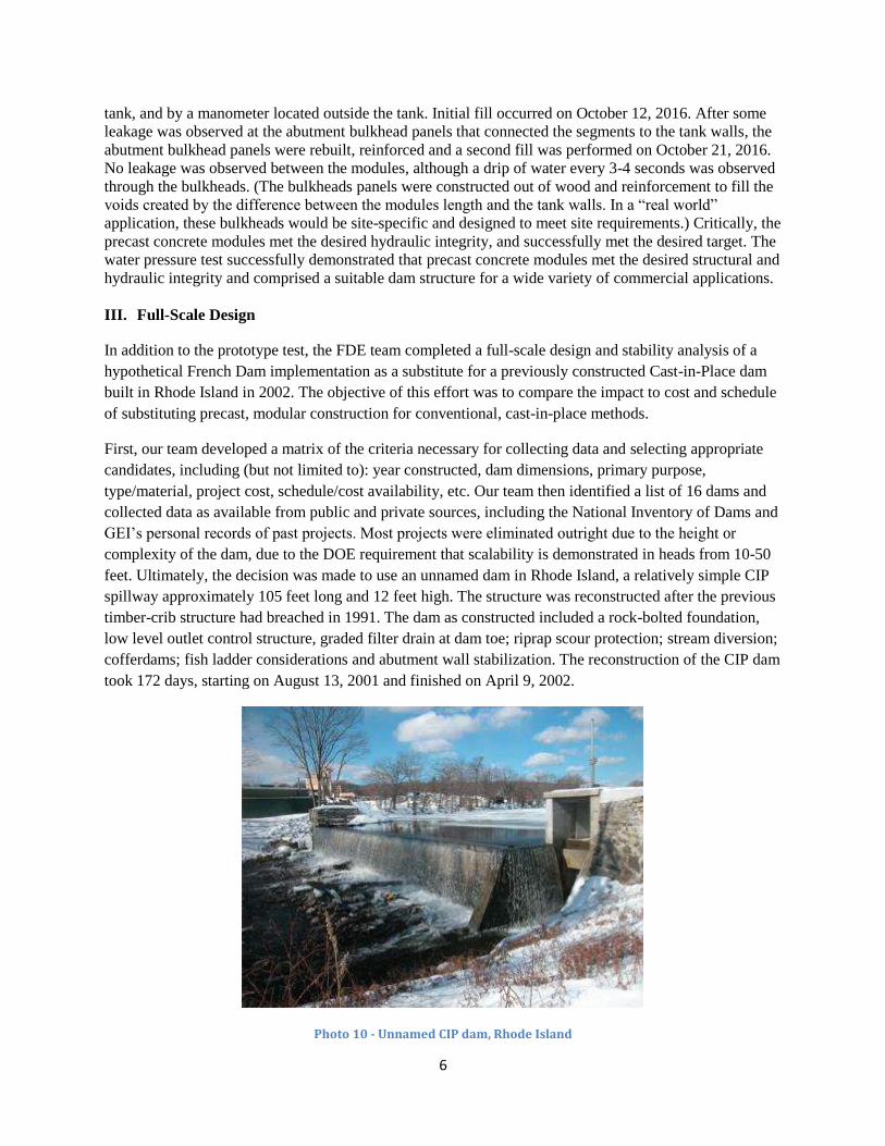
took 172 days, starting on August 13, 2001 and finished on April 9, 2002.
Photo 10 - Unnamed CIP dam, Rhode Island
7
The French Dam was modified from the original design, consistent with the goals of the project. The goal
was to substitute the Precast French Dam technology for as much of the cast-in-place dam as possible.
With a design height similar to the prototype test, GEI designed the French Dam with similar module
sizes and arrangement. The French Dam height of 15.5 feet was based on a crest elevation of 93.5 feet
and a bedrock elevation of 78 feet, slightly higher than the original constructed dam. The French Dam
design layout consisted of two rows of 13 precast concrete modules (26 modules total), and 2-inch-
diameter rock anchors spaced at 4 feet with 20 foot rock embedment. Each module was 8 ft. x 8 ft. in
plan, and 7.2 feet tall. A lean concrete mat and granite stone cap (to match the existing look) are included
to complete the dam height3.
GEI performed a stability analysis for 3 conditions (normal operating conditions, 100-year flood
discharge, and normal operation with earthquake4.) The stability analysis includes the clamping action of
the rock anchor to resist both sliding and overturning loads. Each load case was evaluated to determine
the factor of safety against sliding, eccentricity, foundation bearing pressures, and concrete stress levels.
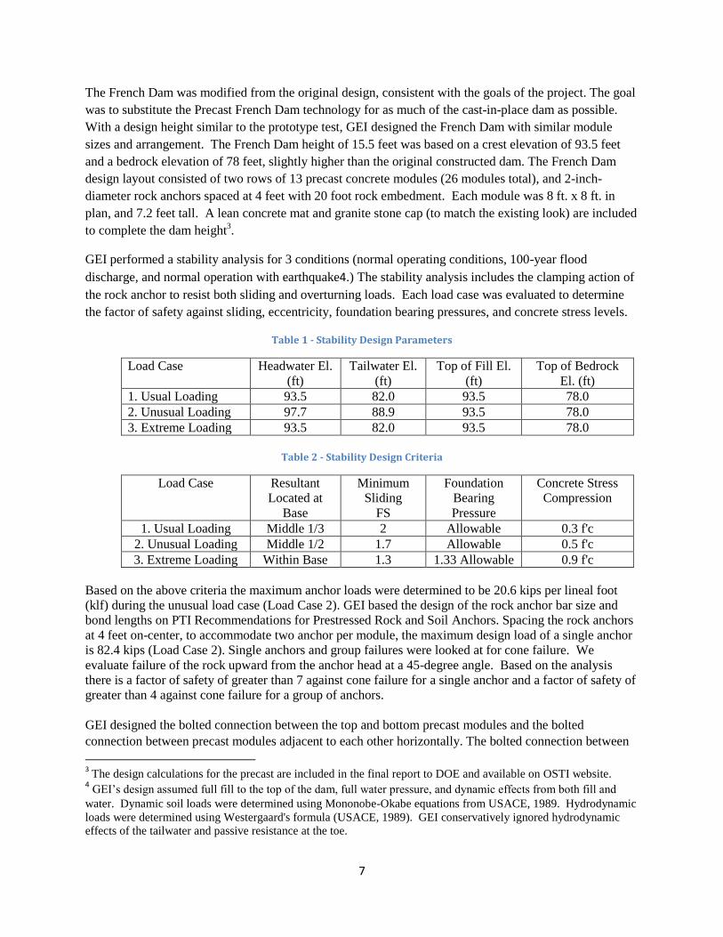
Table 1 - Stability Design Parameters
Load Case Headwater El.
(ft)
Tailwater El.
(ft)
Top of Fill El.
(ft)
Top of Bedrock
El. (ft)
1. Usual Loading 93.5 82.0 93.5 78.0
2. Unusual Loading 97.7 88.9 93.5 78.0
3. Extreme Loading 93.5 82.0 93.5 78.0
Table 2 - Stability Design Criteria
Load Case Resultant
Located at
Base
Minimum
Sliding
FS
Foundation
Bearing
Pressure
Concrete Stress
Compression
1. Usual Loading Middle 1/3 2 Allowable 0.3 f'c
2. Unusual Loading Middle 1/2 1.7 Allowable 0.5 f'c
3. Extreme Loading Within Base 1.3 1.33 Allowable 0.9 f'c
Based on the above criteria the maximum anchor loads were determined to be 20.6 kips per lineal foot
(klf) during the unusual load case (Load Case 2). GEI based the design of the rock anchor bar size and
bond lengths on PTI Recommendations for Prestressed Rock and Soil Anchors. Spacing the rock anchors
at 4 feet on-center, to accommodate two anchor per module, the maximum design load of a single anchor
is 82.4 kips (Load Case 2). Single anchors and group failures were looked at for cone failure. We
evaluate failure of the rock upward from the anchor head at a 45-degree angle. Based on the analysis
there is a factor of safety of greater than 7 against cone failure for a single anchor and a factor of safety of
greater than 4 against cone failure for a group of anchors.
GEI designed the bolted connection between the top and bottom precast modules and the bolted
connection between precast modules adjacent to each other horizontally. The bolted connection between
3 The design calculations for the precast are included in the final report to DOE and available on OSTI website.
4 GEI’s design assumed full fill to the top of the dam, full water pressure, and dynamic effects from both fill and
water. Dynamic soil loads were determined using Mononobe-Okabe equations from USACE, 1989. Hydrodynamic
loads were determined using Westergaard's formula (USACE, 1989). GEI conservatively ignored hydrodynamic
effects of the tailwater and passive resistance at the toe.

8
the top and bottom precast modules (four bolts, one at each corner 9-inches from the edge of concrete)
where designed based on the stability analysis above. GEI designed the bolts for tension, shear, and
combined tension and shear using the load factors from ASCE Strength Design for Reinforced Hydraulic
Structures. The bolted connection between the precast modules (four bolts per module) were designed to
resist the shear force created during a seismic event. The load factors from ASCE Strength Design for
Reinforced Hydraulic Structures were used.
We considered two scenarios to estimate the impact to construction schedule. For Scenario #1, the anchor
bolt and dam footing dates were fixed to the start dates used in the actual reconstruction schedule for the
unnamed Dam. Under this scenario, the French precast reconstruction of unnamed Dam is estimated to
take 118 days, starting on August 13, 2001 and finished on January 23, 2002. The Surface Water Control
and Diversion (Cofferdams) is estimated to be in place for 88 days, from September 24, 2001 until
January 23, 2002. The dam reconstruction including rock anchors, working pad, precast French Dam,
granite capstone, and downstream riprap is estimated to take 54 days, stating October 16, 2001 and
finished on January 2, 2002.
For Scenario #2, we permitted the anchor bolt and dam working pad start dates to move freely based on
predecessor construction activities. For this schedule we have increased the rock anchors duration. In
this Scenario, the French Dam reconstruction of unnamed Dam is estimated to take 88 days, starting on
August 13, 2001 and finished on December 12, 2001. The Surface Water Control and Diversion
(Cofferdams) is estimated to be in place for 58 days, from September 24, 2001 until December 12, 2001.
The dam reconstruction including rock anchors, working pad, French Dam, granite capstone, and
downstream riprap is estimated to take 34 days, stating October 16, 2001 and finished on November 28,
2001.
Under both scenarios, the precast modular installation rate is based on the rate observed during the
prototype installation, at 6 units in fewer than 4 hours or 12 units during an 8-hour shift. The French Dam
would reduce the construction duration considerably. Conservatively, by fixing the start dates of the rock
anchors and footing work of the French Dam to the CIP dam dates, the overall project schedule will be
reduced by 31%, and a readjustment of the anchor bolt and dam working pad installation dates results in a
reduction of 49%.
Table 3 - Schedule Reduction due to French Dam Application
Unnamed Dam – Construction Schedule Comparison
Activity CIP Dam FRENCH Dates Locked FRENCH Dates Free
Days Days % Reduction Days % Reduction
Cofferdams in River 142 88 40% 58 60%
Dam Reconstruction 95 54 40% 34 65%
Total Project 172 118 30% 88 50%
IV. Estimated Cost Savings of Precast vs. Cast in Place
To understand how cost savings can be achieved, GEI developed a generalized design tool to assess
potential configurations and associated costs for a variety of water levels, from 10 to 50 feet of head.
Only external forces were considered and assumed the precast units would act together rigidly so that the
resulting structure acts as an anchored gravity structure. We analyzed the different configurations for

9
stability against sliding and overturning, with a minimum factor of safety of 1.5. Starting at 16-feet high
(3-units high), the precast modular dam was configured with two units at the crest, to provide an adequate
crest width for vehicle access.
Constant exterior size was assumed for the precast units for simplicity, but variable sizes could be
incorporated for different projects. Allowances were made for increasing wall thickness as the height of
the structure increases from a minimum of 8-inches to a maximum of 18-inches. For cases where the
reservoir was within 3-feet of the dam crest, a precast parapet wall was included to maintain freeboard.
The dam was analyzed for reservoir loading with full uplift conditions, with seismic forces tied to the
project test site (Billerica, MA). The seismic force was applied on a simplified basis, with a constant
seismic coefficient applied to the entire mass of the structure. The seismic force was determined based on
the height of the structure and the estimated corresponding approximate period on the design spectra
taken from the USGS design maps website, using the 2010 ASCE 7 mapping for Billerica, MA. The
maximum seismic force applied was 0.23g, and applied for structure heights less than 31 feet.
The external forces were resisted by the weight of the precast units, anchorage forces, tailwater forces,
and mechanical connections between modules. A friction factor of 0.7 was applied, because the structure
will be constructed atop a concrete mud mat. For simplicity we assumed a single anchor size, capacity,
and cost for all configurations. This would be revised during design to fit any specific project. Our
assumptions were a bar anchor installed to approximately 20-feet, with a nominal capacity of 60-kips
each.
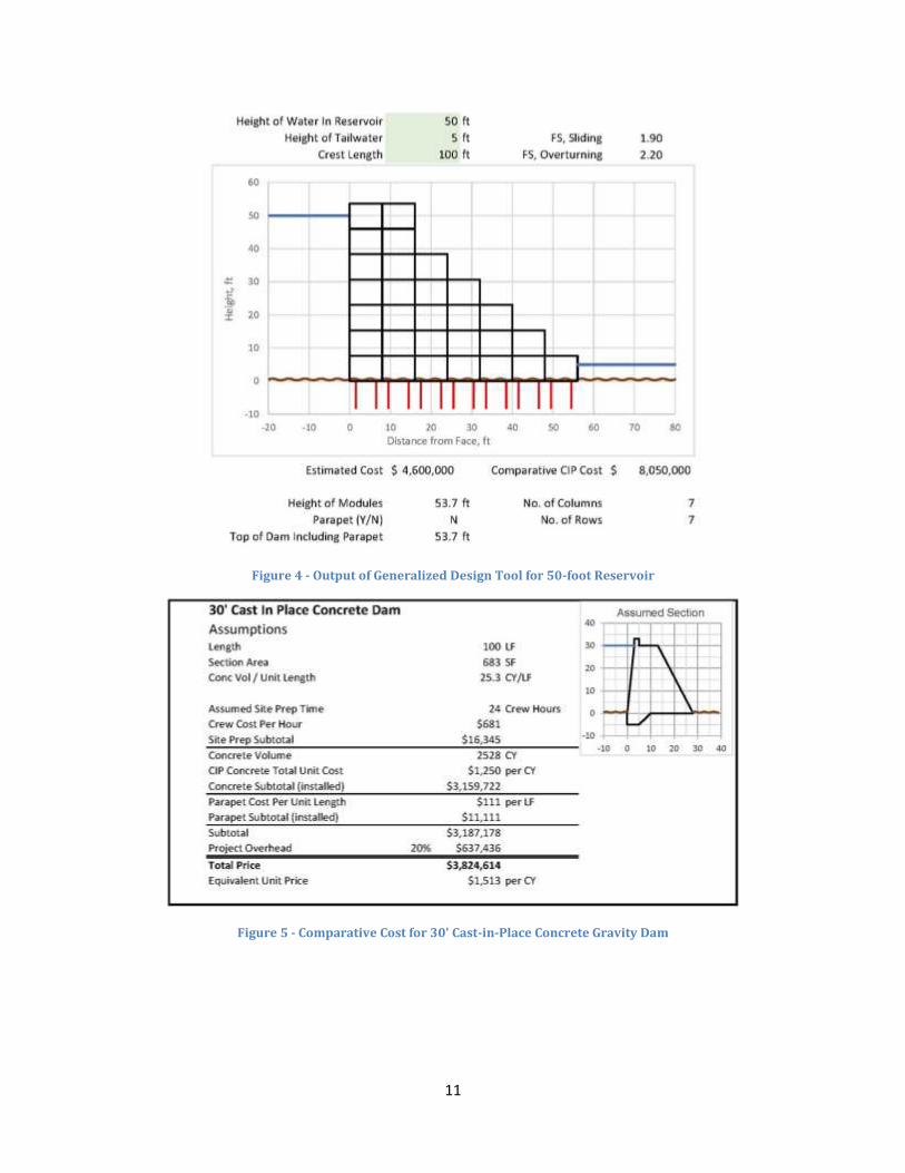
Figures 10, 11 and 12 below are snapshots of the generalized design tool output showing the
configuration and conceptual cost estimate for reservoir heights of 22, 30, and 50 feet. Potential modular
dam configurations resemble the shape of traditional cast-in-place structures. The main difference is that
the structure is less dense, which is largely offset by the use of anchors to provide additional normal force
at the base of the structure. For a given precast configuration, we estimated a comparative cost for a
traditional cast-in-place gravity dam. The cost of the modular precast structure was estimated in the same
way as described in the Unnamed Dam Rehabilitation Cost Estimate section above, with a few minor
changes to generalize the design. Specifically, we assumed more anchors would be necessary in the
generalized design, and we assumed a slightly larger standard unit size. To compare against a
cast-in-place alternative, we estimated costs for 22, 30, and 50-foot high cast-in-place concrete gravity
dams based on an assumed section geometry and unit costs. The 22-foot structure was the same as the
Unnamed Dam, except that it was made slightly larger to accommodate freeboard, because the
comparative costs are for non-overflow sections of the structure.

10
Figure 2 - Output of Generalized Design Tool for 22-foot Reservoir
Figure 3 - Output of Generalized Design Tool for 30-foot Reservoir
11
Figure 4 - Output of Generalized Design Tool for 50-foot Reservoir
Figure 5 - Comparative Cost for 30' Cast-in-Place Concrete Gravity Dam

12
Figure 6 - Comparative Cost for 50’ Cast-in-Place Concrete Gravity Dam
At larger heights, the modular precast dam is expected to become much less expensive than a comparable
cast-in-place concrete dam. This does not account for the other components of the dam such as the
spillway and outlet works which can be a significant proportion of the total project cost, and which are
traditionally incorporated into the structure of a cast-in-place dam.
Table 4 - Summary of Results (CIP vs Precast, 100' Crest Length)
Dam Head CIP Cost Precast Cost Est. Cost Savings
22’ $1,980,000 $900,000 55%
30’ $3,830,000 $1,500,000 60%
50’ $8,050,000 $4,600,000 40%
V. Conclusion
New means and methods of construction are critical to reduce cost and construction time for completion
of new dams and hydropower structures. Modular precast concrete is one approach that can be applied to
standardize and apply repetition in dam segment construction, to seek reduced risk, cost reduction and
schedule improvement goals. Although site-specific aspects will always be important, many elements of
the primary structure can be constructed from precast concrete to enable precast concrete manufacturing,
modularization and achieve economies of scale. The French Dam has precast solutions to reduce cost and
schedule for dam rebuilding and new construction. Precast concrete modules can be designed to include
hydro generation equipment, or water supply conduits, or assembled to fit unique project configurations.
Conventional dams could be replaced by sectional precast concrete modular dams which can be built off-
site and transported to multiple regional projects.
The FDE modules have broad application in both overflow and non-overflow structures, and for both new
and retrofit/rehabilitation construction. The reduced on-site construction time brings significant benefits
to the dam construction industry, by limiting schedule and cost overruns and reducing risk due to weather
delays in the construction process. The primary result of the FDE prototype construction process and

13
corresponding technical evaluation report demonstrated that this new method of construction can improve
the economics and reduce risk for this industry application.
Following the conclusion of a successful test, the FDE Team is now engaging a variety of public and
private sector clients to develop the first commercial project. This includes dam owners, water
infrastructure operators, hydroelectric plant developers and regulatory agencies responsible for dam
safety. Several Northeast dam safety regulators have indicated a willingness to include precast concrete as
an alternative in project specifications in RFIs/RFPs. The French Dam patent portfolio covers modular
precast concrete as applied to new and rehabilitation of dams and existing impoundment structures, and
this technology is currently available for licensing to engineering and construction firms and/or precast
manufacturers.
The FDE prototype precast concrete modules has wide potential for applications, and with adaptation of
its design to actual project sites, can be used not only as a non-overflow structure, but also as an overflow
(spillway), outlet and intake hydraulic structure. Further adaptation of design can be expected based on
actual application for a temporary cofferdam, repair of existing dams and hydraulic structures, and new
dam and hydraulic structures. The modularization concept has the potential of wide application and can
be customized to any low head dam site. It offers the advantage of high quality control of precast
concrete, increased design standardization, and reduces on-site construction time. It also has the flexibility
to be combined with other traditional construction and concreting means and methods.
For Further Reading: For a complete description of the French Dam prototype project, including full
design calculations and engineering drawings, please see report available on DOE Office of Scientific and
Technical Information entitled: French Modular Impoundment, Deliverable 6.4: Final Cost and
Performance Evaluation, DOE Award: DE-EE0007244, Project Period: 12/01/15 – 12/31/16. For a copy
of this report please contact: [email protected]

14
Bibliography:
Hydro Research Foundation in cooperation with Oak Ridge National Laboratory. (2014). New Pathways
for Hydropower: Getting Hydropower Built—What Does It Take? UT-BATTELLE, LLC
American Society for Civil Engineers. (2017). 2017 Infrastructure Report Card - Dams. ASCE
Massachusetts Institute of Technology. Mission 2012: Clean Water Dams. (n.d.). Retrieved May 02,
2017, from http://web.mit.edu/12.000/www/m2012/finalwebsite/problem/dams.shtml
FRETWELL, S. (2016, October 16). Dams again failing in South Carolina. Retrieved May 02, 2017,
from http://www.thestate.com/news/local/article108153527.html
American Society of Dam Safety Officials. (2015 data). Retrieved May 02, 2017, from
http://www.damsafety.org/community/states/?p=500d3792-cd4c-4888-925a-06c4117ad646
President-elect Trump. (2017). Emergency and National Security Projects.
Union of Concerned Scientists. Heavy Flooding and Global Warming: Is There a Connection? (n.d.).
Retrieved May 02, 2017, from
http://www.ucsusa.org/global_warming/science_and_impacts/impacts/heavy-flooding-and-global-
warming.html#.VsdCa_IrIhc
Stanford University, National Performance of Dam Program
HDR, Inc. Gill’s Creek Watershed: Assessment of Regulated Dams. February 15, 2016. HDR, Inc.
A. (n.d.). Top Issues Facing the Dam Community. Retrieved May 02, 2017, from
http://www.damsafety.org/news/?p=c0fdade4-ab98-4679-be22-e3d7f14e124f
15
AUTHORS
Peter Drown – Peter is President of Cleantech Analytics LLC, a clean energy and water technology
Research and Development firm focused on commercializing solutions to new clean energy and water
challenges. A major focus area for his current clients is transformative hydropower technology and
development approaches that reduce cost for new projects. Peter previously worked with the U.S.
Department of Energy where he developed investment strategy for new hydropower technology projects,
and his work led to record budget requests and innovative funding opportunities. Since that time Peter has
joined the private sector where he assists clean energy firms with project development strategy,
technology commercialization, and environmental compliance. He founded Cleantech Analytics in 2014.
Peter holds an MBA in Finance and Bachelor’s of Science in Economics from the University of Maine in
Orono.
Andrew Sanna, P.E. – Andrew Sanna is Project Manager at GEI Consultants, Inc., Woburn, MA, with a
wide range of experience in engineering analyses, design, and construction management. He has worked
on numerous electrical generation projects (solar, hydroelectric, natural gas, and coal), electrical storage
projects, electrical transmission and distribution projects, dam and levee rehabilitation projects, and
bridge design and construction projects. He received his BS in civil engineering from Clarkson
University, Potsdam, NY.
Norm Bishop, Jr., P.E. – Norm Bishop is a Senior Executive Project Engineer based in Knight Piésold’s
Denver office. He has over 40 years of experience in hydraulic, heavy civil, hydroelectric, pumped
storage, water resources, solar, wind, biomass and biofuel, energy storage, and thermal projects. His
innovative construction and engineering solutions have resulted in significant project cost and time
savings on numerous projects. His expertise includes program and project management, planning,
feasibility studies, site studies, environmental studies, permits and licensing, cost estimating, financial
studies, project financing, engineering, procurement, construction, and commissioning. He has been
involved in multiple national and international award-winning energy projects and has received the ASCE
Rickey Medal in 1999.