Embed Size (px)
Citation preview

Precast Flooring FederationCode of Practice for:
THE SAFE INSTALLATION OF PRECAST CONCRETE FLOORING AND ASSOCIATED COMPONENTS
2013
PREFACE
This Precast Flooring Federation Code of Practice for the safe installation of precast concrete flooring and associated components has now run for several editions and since the first edition in 2001 there have been many developments, not only in Health and Safety legislation, but also in best practice within the industry.
The Code gives a guide to the current best practice, but in an ever-changing situation, can only be totally up-to-date at the time of its publication.
The PFF is committed to achieving a high standard and universal approach to Health and Safety within its membership, and part of this is the provision to employees, customers and designers alike of clearly presented information about the systems of work employed and attendances required.
This edition of the Code of Practice has been some two years in preparation and the patience of the membership and of the Health and Safety Executive, who have provided invaluable assistance with its development, is much appreciated.
This edition will be published almost exclusively as a download from the PFF website, although a number of printed copies will be made available to members, training organisations and the Health and Safety Executive. This document will be updated online.
Installation of precast flooring components is acknowledged to be a potentially high-risk activity, as it involves the use of heavy plant, cranes and personnel working at height. This Code of Practice is, therefore, used as the basis for the training of Installers, Foremen and supervisors to ensure that all have the skills and competence to carry out their roles in a safe manner. This training is predominantly carried out via the training programme developed jointly between the PFF and Proskills.
The Council of the Precast Flooring Federation gratefully acknowledges the help and guidance provided by the Health and Safety Executive in the preparation of this Code and is pleased to be able to include the following Foreword from Heather Bryant of HSE. The PFF has also received support and comment from the Major Contractors Group.
Published and distributed by the Precast Flooring Federation60 Charles StreetLeicesterLE1 1PETel: 0116 253 6161Fax: 0116 251 4568 Email: [email protected]
First published 2001 ISBN 0 9536773 1 1Second edition 2007 ISBN 0 9536773 5 4This edition published 2013 ISBN 978-0-9536773-6-8A catalogue record for this book is available from the British Library
Every effort has been made to ensure that the statements made and advice given provide a safe and accurate guide; however, no liability or responsibility of any kind (including liability for negligence) can be accepted in this respect by the publishers or the authors
i
FOREWORD
HSE encourages and welcomes industry codes of practice such as this produced by the Precast Flooring Federation (PFF), which receive careful consideration and input from key players within the industry who have the health, safety and welfare of those involved in precast flooring work foremost in their mind.
Falls have always been, and remain the biggest cause of deaths and serious injuries in construction. If work at height is planned, including selecting the correct equipment and using it properly, then most accidents involving falls can be prevented. As with previous editions of this code and other similar industry codes of practice, if the guidance within it is properly followed by the industry, then the risks of death and injury from falls and other factors should be greatly reduced.
I am pleased to acknowledge the work of the PFF and those involved in revising this code of practice. It brings together best practice within the industry and has the interest of those involved in the design, specification, use and erection of precast flooring products at heart. It is only by the industry showing leadership, working in partnership, and taking ownership of the management of risk that improvements will be made, and I commend its use to all concerned.
Heather BryantChief Inspector of ConstructionHealth and Safety Executive
Message from PFF Chairman
This is the third edition of the Precast Flooring Federation Code of Practice supported by HSE. We advise you to take a detailed look at the content whenever you are involved in a precast flooring project. This new edition coincides with the launch of the PFF Charter which has been signed by all member companies. Each of them pledges to work to the Code both through their in-house construction teams and with all appointed fixing subcontractors. Conformity with the PFF Code of Practice is subject to an independent audit system which will start on 1 April 2013.
This is a further significant step in reducing the risk of accidents and injuries in the installation of floors and staircases - we anticipate increasing use of precast flooring systems in the upper floors of houses as demand for quiet and durable floors grows.
Whether you are a client, a designer or a contractor, by working with PFF members you can help to ensure safety on your sites. For details of the PFF Charter, its signatories and the audit system please visit www.precastfloors.info where you can also download this Code of Practice.

ii
Acknowledgements
The members of the Precast Flooring Federation and stakeholders have made this publication possible. Whilst many individuals have contributed, the following are amongst those who deserve particular mention:
Mark Bradley – Charcon
Nick Clarke – Hanson
John Cotton – Hanson
William Doherty – Creagh
John Duffy – Hanson
Graham Keenor – H + H
Norman Richards – Richards Associates
Paul Thomas – HSE

iii
0.1 0.1 DEFINITIONS 1
0.2 BIBLIOGRAPHY 3
1 MANAGEMENT OF HEALTH AND SAFETY 5
2 SAFE WORKING METHOD STATEMENTS AND PRE-START CHECKS 13
3 TRAINING AND CERTIFICATION 17
4 DESIGN CONSIDERATIONS 19
5 CONTRACTOR’S RESPONSIBILITIES 29
6 COMPANY REPRESENTATIVE’S ROLE 31
7 FOREMAN’S ROLE 33
8 TRANSPORTATION OF COMPONENTS AND ACCESS TO SITE 35
9 ON-SITE STORAGE OF COMPONENTS 37
10 SAFE USE OF CRANES, FORK LIFTS AND OTHER LIFTING EQUIPMENT 39
11 MOVEMENT OF UNITS BY OTHER MEANS 65
12 ADDITIONAL ON-SITE WORKS 67
13 ACCESS TO WORKING AREA , WORK AT HEIGHT ETC 71
14 PROTECTION OF THIRD PARTIES 85
15 SUPPLIER AND SUB-CONTRACTOR COMPETENCY ASSESSMENT 87
APPENDIX A HEALTH, SAFETY AND WELFARE ATTENDANCES 89
APPENDIX B CONSTRUCTION (DESIGN AND MANAGEMENT) REGULATIONS 93
APPENDIX C SAFETY 97
Code of Practice for: The safe installation of precast concrete flooring and associated components
CONTENTS See over for detailed contents

iv
DETAILED CONTENTS
0.1 DEFINITIONS 1
0.2 BIBLIOGRAPHY 3
1 MANAGEMENT OF HEALTH AND SAFETY 5
1.1 Management of Health And Safety at Work Regulations and . . . . . . . . . . . . . . . . . . . . .5Approved Code of Practice
1.2 Work at height . . . . . . . . . . . . . . . . . . . . . . . . . . . . . . . . . . . . . . . . . . . . . . . . . . . . . . . . .7 1.3 Lifting operations . . . . . . . . . . . . . . . . . . . . . . . . . . . . . . . . . . . . . . . . . . . . . . . . . . . . . . .7 1.4 Manual handling operations . . . . . . . . . . . . . . . . . . . . . . . . . . . . . . . . . . . . . . . . . . . . . .7 1.5 Noise at work . . . . . . . . . . . . . . . . . . . . . . . . . . . . . . . . . . . . . . . . . . . . . . . . . . . . . . . . .8 1.6 Vibration at work . . . . . . . . . . . . . . . . . . . . . . . . . . . . . . . . . . . . . . . . . . . . . . . . . . . . . . .8 1.7 Personal protective equipment at work . . . . . . . . . . . . . . . . . . . . . . . . . . . . . . . . . . . . .9 1.8 Provision and use of Work Equipment Regulations . . . . . . . . . . . . . . . . . . . . . . . . . . .10 1.9 Welfare facilities . . . . . . . . . . . . . . . . . . . . . . . . . . . . . . . . . . . . . . . . . . . . . . . . . . . . . .10 1.10 Control of Substances Hazardous to Health (COSHH) . . . . . . . . . . . . . . . . . . . . . . . . .10 1.11 Occupational health . . . . . . . . . . . . . . . . . . . . . . . . . . . . . . . . . . . . . . . . . . . . . . . . . . .11
2 SAFE WORKING METHOD STATEMENTS AND PRE-START CHECKS 13
2.1 Introduction . . . . . . . . . . . . . . . . . . . . . . . . . . . . . . . . . . . . . . . . . . . . . . . . . . . . . . . . . .13 2.2 Content of Safe Working Method Statement . . . . . . . . . . . . . . . . . . . . . . . . . . . . . . . . .13 2.3 Communication of the Safe Working Method Statement . . . . . . . . . . . . . . . . . . . . . . .14 2.4 Additions to the Safe Working Method Statement . . . . . . . . . . . . . . . . . . . . . . . . . . . .14 2.5 Special considerations . . . . . . . . . . . . . . . . . . . . . . . . . . . . . . . . . . . . . . . . . . . . . . . . . .15 2.6 Pre-start daily checks . . . . . . . . . . . . . . . . . . . . . . . . . . . . . . . . . . . . . . . . . . . . . . . . . . .15
3 TRAINING AND CERTIFICATION 17
3.1 Introduction . . . . . . . . . . . . . . . . . . . . . . . . . . . . . . . . . . . . . . . . . . . . . . . . . . . . . . . . . .17 3.2 Scope . . . . . . . . . . . . . . . . . . . . . . . . . . . . . . . . . . . . . . . . . . . . . . . . . . . . . . . . . . . . . . .17 3.3 Responsibility . . . . . . . . . . . . . . . . . . . . . . . . . . . . . . . . . . . . . . . . . . . . . . . . . . . . . . . . .17 3.4 General procedure . . . . . . . . . . . . . . . . . . . . . . . . . . . . . . . . . . . . . . . . . . . . . . . . . . . . .17 3.5 Training . . . . . . . . . . . . . . . . . . . . . . . . . . . . . . . . . . . . . . . . . . . . . . . . . . . . . . . . . . . . . .17 3.6 Certification/competency . . . . . . . . . . . . . . . . . . . . . . . . . . . . . . . . . . . . . . . . . . . . . . .18
4 DESIGN CONSIDERATIONS 19
4.1 The existing environment . . . . . . . . . . . . . . . . . . . . . . . . . . . . . . . . . . . . . . . . . . . . . . . .19 4.2 Design and planning . . . . . . . . . . . . . . . . . . . . . . . . . . . . . . . . . . . . . . . . . . . . . . . . . . .19 4.3 Construction phase . . . . . . . . . . . . . . . . . . . . . . . . . . . . . . . . . . . . . . . . . . . . . . . . . . . .20 4.4 Lifting, placing and safe handling of units . . . . . . . . . . . . . . . . . . . . . . . . . . . . . . . . . . .21 4.5 Installation of precast concrete floors onto steelwork . . . . . . . . . . . . . . . . . . . . . . . . . .22 4.6 Installation of precast concrete floors onto masonry . . . . . . . . . . . . . . . . . . . . . . . . . . .22 4.7 Imposed loads during the construction phase . . . . . . . . . . . . . . . . . . . . . . . . . . . . . . . .26 4.8 Stability of supporting structure during installation . . . . . . . . . . . . . . . . . . . . . . . . . . . .26 4.9 The Health and Safety File . . . . . . . . . . . . . . . . . . . . . . . . . . . . . . . . . . . . . . . . . . . . . . .27 4.10 Other construction methods . . . . . . . . . . . . . . . . . . . . . . . . . . . . . . . . . . . . . . . . . . . . .27

v
5 CONTRACTOR’S RESPONSIBILITIES 29
5.1 Attendances . . . . . . . . . . . . . . . . . . . . . . . . . . . . . . . . . . . . . . . . . . . . . . . . . . . . . . . . . .29 5.2 Management of construction works . . . . . . . . . . . . . . . . . . . . . . . . . . . . . . . . . . . . . . . .29 5.3 Prevention of damage to precast units . . . . . . . . . . . . . . . . . . . . . . . . . . . . . . . . . . . . .29 5.4 Handrailing to precast stair units . . . . . . . . . . . . . . . . . . . . . . . . . . . . . . . . . . . . . . . . . .29
6 COMPANY REPRESENTATIVE’S ROLE 31
6.1 Agreed sequence of installation . . . . . . . . . . . . . . . . . . . . . . . . . . . . . . . . . . . . . . . . . . .31 6.2 Method of lifting . . . . . . . . . . . . . . . . . . . . . . . . . . . . . . . . . . . . . . . . . . . . . . . . . . . . . . .31 6.3 Site access. . . . . . . . . . . . . . . . . . . . . . . . . . . . . . . . . . . . . . . . . . . . . . . . . . . . . . . . . . . .32 6.4 Attendances liaison . . . . . . . . . . . . . . . . . . . . . . . . . . . . . . . . . . . . . . . . . . . . . . . . . . . . .32 6.5 Supervision of installation . . . . . . . . . . . . . . . . . . . . . . . . . . . . . . . . . . . . . . . . . . . . . . . .32
7 FOREMAN’S ROLE 33
7.1 Working to sequence . . . . . . . . . . . . . . . . . . . . . . . . . . . . . . . . . . . . . . . . . . . . . . . . . . .33 7.2 Pre-start checks . . . . . . . . . . . . . . . . . . . . . . . . . . . . . . . . . . . . . . . . . . . . . . . . . . . . . . . .33 7.3 Supervision of installation . . . . . . . . . . . . . . . . . . . . . . . . . . . . . . . . . . . . . . . . . . . . . . . .33 7.4 Workmanship . . . . . . . . . . . . . . . . . . . . . . . . . . . . . . . . . . . . . . . . . . . . . . . . . . . . . . . . .34
8 TRANSPORTATION OF COMPONENTS AND ACCESS TO SITE 35
8.1 The stacking and making secure of loads . . . . . . . . . . . . . . . . . . . . . . . . . . . . . . . . . . . .35 8.2 Loading sequence . . . . . . . . . . . . . . . . . . . . . . . . . . . . . . . . . . . . . . . . . . . . . . . . . . . . .35 8.3 Site access. . . . . . . . . . . . . . . . . . . . . . . . . . . . . . . . . . . . . . . . . . . . . . . . . . . . . . . . . . . .35 8.4 Off-loading . . . . . . . . . . . . . . . . . . . . . . . . . . . . . . . . . . . . . . . . . . . . . . . . . . . . . . . . . . .35 8.5 Inspection of precast concrete flooring and other components prior to installation. . . . .36
9 ON-SITE STORAGE OF COMPONENTS 37
9.1 Stacking at ground level . . . . . . . . . . . . . . . . . . . . . . . . . . . . . . . . . . . . . . . . . . . . . . . . .37 9.2 Temporary storage on installed flooring . . . . . . . . . . . . . . . . . . . . . . . . . . . . . . . . . . . . .37
10 SAFE USE OF CRANES, FORK LIFTS AND OTHER LIFTING EQUIPMENT 39
10.1 Introduction . . . . . . . . . . . . . . . . . . . . . . . . . . . . . . . . . . . . . . . . . . . . . . . . . . . . . . . . . .39 10.2 Management of the lifting operation. . . . . . . . . . . . . . . . . . . . . . . . . . . . . . . . . . . . . . .39 10.3 Control of the lifting operation . . . . . . . . . . . . . . . . . . . . . . . . . . . . . . . . . . . . . . . . . . .40 10.4 Crane hire or contract lift . . . . . . . . . . . . . . . . . . . . . . . . . . . . . . . . . . . . . . . . . . . . . . . .41 10.5 Planning the lifting operation. . . . . . . . . . . . . . . . . . . . . . . . . . . . . . . . . . . . . . . . . . . . .42 10.6 Selection and duties of personnel . . . . . . . . . . . . . . . . . . . . . . . . . . . . . . . . . . . . . . . . .43 10.7 Selection of cranes . . . . . . . . . . . . . . . . . . . . . . . . . . . . . . . . . . . . . . . . . . . . . . . . . . . . .45 10.8 Safety . . . . . . . . . . . . . . . . . . . . . . . . . . . . . . . . . . . . . . . . . . . . . . . . . . . . . . . . . . . . . . .45 10.9 Siting of cranes. . . . . . . . . . . . . . . . . . . . . . . . . . . . . . . . . . . . . . . . . . . . . . . . . . . . . . . .48 10.10 Hardstanding preparation . . . . . . . . . . . . . . . . . . . . . . . . . . . . . . . . . . . . . . . . . . . . . . .5010.11 ̀Permit to lift' system/confirmation to process . . . . . . . . . . . . . . . . . . . . . . . . . . . . . . .5210.12 Proximity hazards . . . . . . . . . . . . . . . . . . . . . . . . . . . . . . . . . . . . . . . . . . . . . . . . . . . . . .5210.13 Types of crane . . . . . . . . . . . . . . . . . . . . . . . . . . . . . . . . . . . . . . . . . . . . . . . . . . . . . . . .5410.14 Start of the lifting operation. . . . . . . . . . . . . . . . . . . . . . . . . . . . . . . . . . . . . . . . . . . . . .5610.15 Examples of safe working practice indicated by use of typical trigonometry . . . . . . . .60

vi
11 MOVEMENT OF UNITS BY OTHER MEANS 65
11.1 Barring . . . . . . . . . . . . . . . . . . . . . . . . . . . . . . . . . . . . . . . . . . . . . . . . . . . . . . . . . . . . . .65 11.2 Jacking . . . . . . . . . . . . . . . . . . . . . . . . . . . . . . . . . . . . . . . . . . . . . . . . . . . . . . . . . . . . . .65 11.3 Other means of installing or moving components. . . . . . . . . . . . . . . . . . . . . . . . . . . . .66
12 ADDITIONAL ON-SITE WORKS 67
12.1 Temporary structural support . . . . . . . . . . . . . . . . . . . . . . . . . . . . . . . . . . . . . . . . . . . . .67 12.2 Propping. . . . . . . . . . . . . . . . . . . . . . . . . . . . . . . . . . . . . . . . . . . . . . . . . . . . . . . . . . . . .67 12.3 In-situ concrete. . . . . . . . . . . . . . . . . . . . . . . . . . . . . . . . . . . . . . . . . . . . . . . . . . . . . . . .67 12.4 Forming holes . . . . . . . . . . . . . . . . . . . . . . . . . . . . . . . . . . . . . . . . . . . . . . . . . . . . . . . .68 12.5 Cutting units on site . . . . . . . . . . . . . . . . . . . . . . . . . . . . . . . . . . . . . . . . . . . . . . . . . . .69
13 ACCESS TO WORKING AREA , WORK AT HEIGHT ETC 71
13.1 Introduction . . . . . . . . . . . . . . . . . . . . . . . . . . . . . . . . . . . . . . . . . . . . . . . . . . . . . . . . . .71 13.2 General principles for control measures . . . . . . . . . . . . . . . . . . . . . . . . . . . . . . . . . . . .71 13.3 Safe access to the working area. . . . . . . . . . . . . . . . . . . . . . . . . . . . . . . . . . . . . . . . . . .71 13.4 Working at height – control measures . . . . . . . . . . . . . . . . . . . . . . . . . . . . . . . . . . . . . .72 13.5 T-beam and block above ground floor level . . . . . . . . . . . . . . . . . . . . . . . . . . . . . . . . .78 13.6 Staircases . . . . . . . . . . . . . . . . . . . . . . . . . . . . . . . . . . . . . . . . . . . . . . . . . . . . . . . . . . . .78 13.7 Falls from delivery vehicles. . . . . . . . . . . . . . . . . . . . . . . . . . . . . . . . . . . . . . . . . . . . . . .82 13.8 Use of ladders . . . . . . . . . . . . . . . . . . . . . . . . . . . . . . . . . . . . . . . . . . . . . . . . . . . . . . . .82 13.9 Rescue procedures. . . . . . . . . . . . . . . . . . . . . . . . . . . . . . . . . . . . . . . . . . . . . . . . . . . . .83
14 PROTECTION OF THIRD PARTIES 85
14.1 Other trades or persons on site . . . . . . . . . . . . . . . . . . . . . . . . . . . . . . . . . . . . . . . . . . .85 14.2 Members of the public. . . . . . . . . . . . . . . . . . . . . . . . . . . . . . . . . . . . . . . . . . . . . . . . . .85
15 SUPPLIER AND SUB-CONTRACTOR COMPETENCY ASSESSMENT 87
15.1 Introduction . . . . . . . . . . . . . . . . . . . . . . . . . . . . . . . . . . . . . . . . . . . . . . . . . . . . . . . . . .87 15.2 Assessment criteria. . . . . . . . . . . . . . . . . . . . . . . . . . . . . . . . . . . . . . . . . . . . . . . . . . . . .87
APPENDIX A HEALTH, SAFETY AND WELFARE ATTENDANCES 89
APPENDIX B CONSTRUCTION (DESIGN AND MANAGEMENT) REGULATIONS 93
APPENDIX C SAFETY 97
C1 HSE General Guidance on Manual Handling, Parts 1, 2, and 3 . . . . . . . . . . . . . . . . . .97 C2 Example Safe Working Statement . . . . . . . . . . . . . . . . . . . . . . . . . . . . . . . . . . . . . . . . .99 C3 Example site-specific COSHH Assessment and Control Plan - Petrol . . . . . . . . . . . . .102 C4 Example site-specific COSHH Assessment and Control Plan - Wet concrete . . . . . . .104 C5 Example site-specific COSHH Assessment and Control Plan - Cured concrete . . . . .106 C6 Example guidance on minimum standards for PPE . . . . . . . . . . . . . . . . . . . . . . . . . . .108

FLO
OR
ING
CO
DE
: D
EFI
NIT
ION
S
1
0.1 0.1 DEFINITIONS
Most of the terms used in this document are in common use. However, the following definitions are intended to remove any ambiguity:
Appointed Person: The person employed by the ‘Company’ to have overall control of the lifting operation and to act on behalf of the ‘Company’. The Appointed Person must have adequate training and experience to ensure the implementation of a safe system of work.
As Installed Drawing: The layout drawings confirming actually ‘as installed’ positions of precast flooring/component positions, issued for the client’s safety file.
Attendances: The standard PFF Health, Safety and Welfare Attendances, a copy of which is included as Appendix A to this Code of Practice.
Banksman: A person who has been suitably trained in giving signals to direct and control site traffic.
Building Designer: The designer of the building or structure receiving the precast flooring components.
CDM Coordinator: The individual or organisation appointed by the client as CDM Coordinator under the Construction (Design and Management) Regulations.
Certificated: Having been trained and qualified to fulfil a particular role. Generally, holding a valid licence/certificate of training gained by attending a recognised course of instruction for the task in question.
Company: The supplier and/or installer of precast concrete components and associated items and services
Company Representative: A Supervisor/Contracts Manager (usually travelling) in the Installation Company’s employ with a responsibility for a number of contracts. A Competent Person trained to assess all health, safety and welfare arrangements in relation to company operations.
Competent Person: The person is regarded as competent if they have 'sufficient training and experience or knowledge and other qualities to properly assist the employer to meet his safety obligations'.
Components: Any member, article, or item comprised of precast concrete or ancillary metalwork.
Contractor: “The ‘Contractor’ shall mean the precast concrete sub-contractor’s client, who is responsible for coordinating all Principal Contractor requirements and attendances for the contract. Where the ‘Contractor’ has overall responsibility for the Construction Phase of the project the ‘Contractor’ shall also mean the ‘Principal Contractor’.”
Contractor’s Site Representative: The person in charge of the day-to-day running of a particular site or project, i.e. Site Manager, Site Agent, General Foreman, Project/Contracts Manager.
Crane Coordinator: The person who plans and directs the sequence of operations of cranes to ensure that they do not collide with other cranes, loads and other equipment.
Crane Operator: A competent and trained person responsible for the correct operation of the crane in accordance with the Manufacturer’s Operating Instructions, the Safe Working Method Statement and directions from the nominated Slinger/Signaller.
Crane Supervisor: The person designated by the ‘Appointed Person’ to supervise the lifting operations, where the Appointed Person has deemed the operations as basic or standard, as defined by BS 7121–3: 2000 Section 4.8.
Designer: The person or persons who produces specifications, estimates, drawings, details, designs or calculations for a particular contract.
2
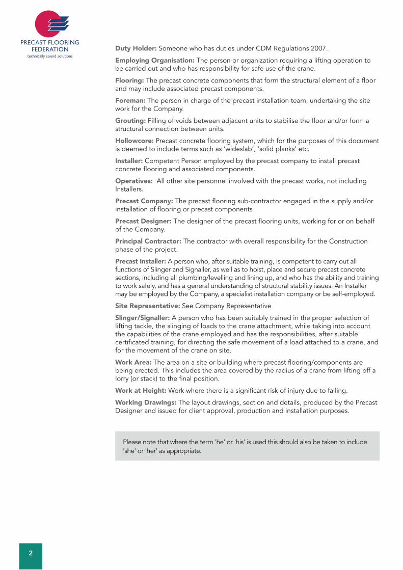
Duty Holder: Someone who has duties under CDM Regulations 2007.
Employing Organisation: The person or organization requiring a lifting operation to be carried out and who has responsibility for safe use of the crane.
Flooring: The precast concrete components that form the structural element of a floor and may include associated precast components.
Foreman: The person in charge of the precast installation team, undertaking the site work for the Company.
Grouting: Filling of voids between adjacent units to stabilise the floor and/or form a structural connection between units.
Hollowcore: Precast concrete flooring system, which for the purposes of this document is deemed to include terms such as ‘wideslab’, ‘solid planks’ etc.
Installer: Competent Person employed by the precast company to install precast concrete flooring and associated components.
Operatives: All other site personnel involved with the precast works, not including Installers.
Precast Company: The precast flooring sub-contractor engaged in the supply and/or installation of flooring or precast components
Precast Designer: The designer of the precast flooring units, working for or on behalf of the Company.
Principal Contractor: The contractor with overall responsibility for the Construction phase of the project.
Precast Installer: A person who, after suitable training, is competent to carry out all functions of Slinger and Signaller, as well as to hoist, place and secure precast concrete sections, including all plumbing/levelling and lining up, and who has the ability and training to work safely, and has a general understanding of structural stability issues. An Installer may be employed by the Company, a specialist installation company or be self-employed.
Site Representative: See Company Representative
Slinger/Signaller: A person who has been suitably trained in the proper selection of lifting tackle, the slinging of loads to the crane attachment, while taking into account the capabilities of the crane employed and has the responsibilities, after suitable certificated training, for directing the safe movement of a load attached to a crane, and for the movement of the crane on site.
Work Area: The area on a site or building where precast flooring/components are being erected. This includes the area covered by the radius of a crane from lifting off a lorry (or stack) to the final position.
Work at Height: Work where there is a significant risk of injury due to falling.
Working Drawings: The layout drawings, section and details, produced by the Precast Designer and issued for client approval, production and installation purposes.
Please note that where the term 'he' or 'his' is used this should also be taken to include 'she' or 'her' as appropriate.

3
FLO
OR
ING
CO
DE
: B
IBLI
OG
RA
PHY
0.2 0.2 BIBLIOGRAPHY
This list is not exhaustive, but provides a helpful pointer to useful publications. Note: Please ensure that you refer to the latest edition of these references.
Her Majesty's Government
Health and Safety at Work etc. Act 1974 The Management of Health and Safety at Work Regulations 1999 The Work at Height Regulations 2005The Health and Safety (First Aid) Regulations 1981 The Control of Noise at Work Regulations 2005 The Electricity at Work Regulations 1989 The Personal Protective Equipment at Work Regulations 1992 The Provision and Use of Work Equipment Regulations 1998 The Lifting Operations and Lifting Equipment Regulations 1998 The Manual Handling Operations Regulations 1992 The Control of Substances Hazardous to Health Regulations 2002 The Construction (Design and Management) Regulations 2007 The Reporting of Injuries, Diseases and Dangerous Occurrences Regulations 1995 The Control of Vibration at Work Regulations 2005The Road and Streetworks Act 1991
Health and Safety Executive
GS 6 Avoidance of danger from overhead electrical lines 1997HSG 141 Electrical safety on construction sitesHSG 144 The safe use of vehicles on construction sitesHSG 149 Backs for the future – safe manual handling in constructionHSG 150 Health and safety in constructionCIS 10 Tower scaffolds (Rev. 4, 2006)CIS 37 Handling heavy blocksCIS 36 Silica dust. (Rev.1 Nov. 2004) CIS 54 Dust control on cut-off saws used for stone or concrete cutting
(Rev. 1. Feb. 2012) Notification of conventional tower crane regulations 2010: Guidance on complying with the RegulationsInformation Sheet MISC 614 Preventing falls from boom type mobile elevating work platformsManaging health and safety in construction
British Standards Institution
British Standards and other guidance notes are issued on a continuing basis and users of this Code of Practice should acquaint themselves with the latest updates and revisions.
BS 5975 Code of Practice for falseworkBS 7121 Code of Practice for safe use of cranes – Parts 1, 2, 3 and 5.BS 5628 Code of Practice for use of masonryBS EN 1992–1–1 Design of concrete structures

4
BS EN 818–4 Guidance for the purchaser and user of mechanically assembled slings
PAS 59 2004 Filled collective fall arrest systems
Construction Industry Research and Information Association
CIRIA Special Publication SP 130 Site Safety HandbookCIRIA publication C703 Crane stability on siteCIRIA publication C654 Tower crane stability
The National Access & Scaffold Confederation
TG20:08 Guide to good practice for scaffolding with tubes and fittings, Vols 1 & 2.TG20:08 Toolbox talk pocket guide to above

FLO
OR
ING
CO
DE
: M
AN
AG
EM
EN
T O
F H
EA
LTH
AN
D S
AFE
TY
5
1 1 MANAGEMENT OF HEALTH AND SAFETY
The Health and Safety at Work etc Act 1974 places several general duties on employers, employees and others. Regulations are made under Section 16 of the Act. The Regulations referred to in the introductory notes below are a legal requirement and must be adhered to at all times. For more information, refer to the documents themselves, listed in the References, and where necessary obtain competent, professional advice and approval on safety matters.
1.1 Management of Health and Safety at Work Regulations and Approved Code of PracticeThe Management of Health and Safety at Work Regulations requires all employers and self-employed Operatives to assess the risk to the health and safety of workers and any others who may be affected by the work carried out.
Assessments will help to identify all the protective and preventative measures that need to be taken to comply with legislation to ensure that health and safety standards are maintained. Guidance on the procedures for risk assessment can be found in the Approved Code of Practice under Management of Health and Safety at Work Regulations, which includes advice on the selection of preventative and protective measures.
Before an assessment of risk can be made it is important to understand the terms used, the two most important being:
Hazard – is something with the potential to cause harm,
Risk – expresses the likelihood that the harm from a particular hazard is realised.
Most employers will be capable of undertaking the risk assessment themselves using expertise within their own organisations. Where there are complex hazards or equipment, it may be necessary to employ the help of external health and safety professionals.
The key actions to be taken can be summarised as below: These Regulations require an employer to make a suitable assessment of the risks to the health and safety of employees and others who may be exposed to those risks. This includes contractors or temporary staff engaged for specific work. Where the risk is considered to be significant, the assessment must be recorded in writing and should identify those personnel especially at risk. Risk assessments must be regularly reviewed and altered if they are no longer valid or circumstances/conditions have changed significantly. A nominated Competent Person (or persons if required) must be appointed to assist in complying with the regulations. Emergency procedures must be established, and Competent Persons nominated to implement them. Information must be provided to the employees on the risks identified, the control measures to be taken, the names of the Competent Persons and information on the risks identified where employers share work areas. Training must be given to employees in respect of the duties placed upon them by the Regulations, at induction when first employed, when transferred, or if the job changes. This training must be updated and repeated periodically to take account of any changes.
In addition employees have certain duties under the Regulations: To make full and proper use of anything provided by the employer in accordance with the training given. This includes safety equipment, machinery, substances, means of transport, etc.
6
Employees must also inform the Employer (or Nominated Persons) of any dangerous work situation or any matter relating to the employer’s health and safety arrangements.
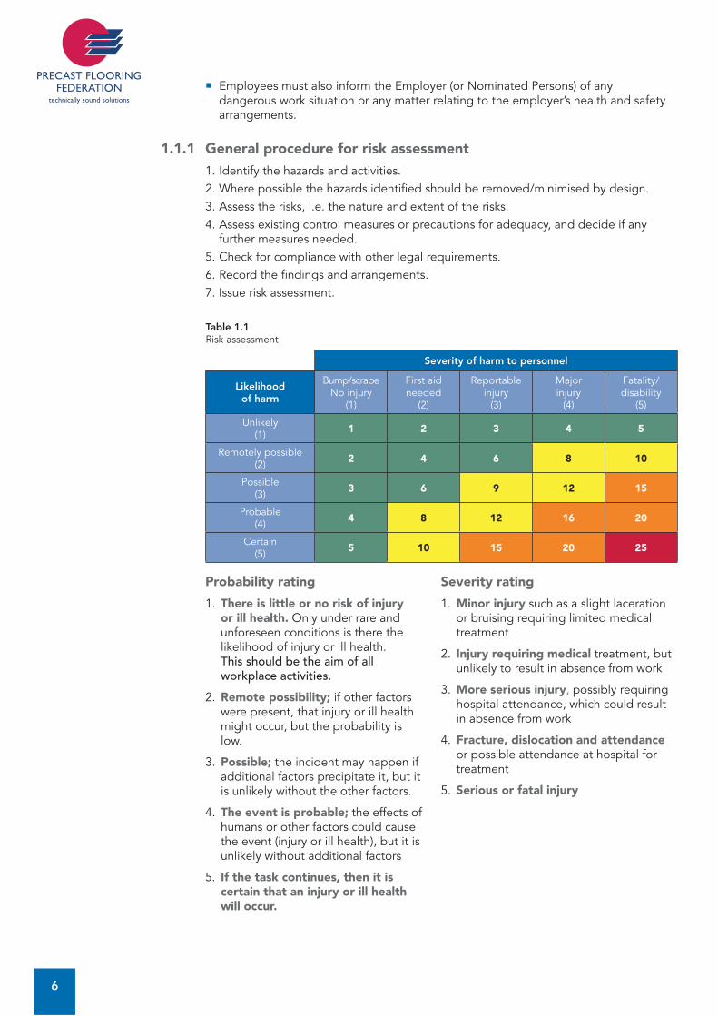
1.1.1 General procedure for risk assessment1. Identify the hazards and activities.2. Where possible the hazards identified should be removed/minimised by design.3. Assess the risks, i.e. the nature and extent of the risks.4. Assess existing control measures or precautions for adequacy, and decide if any
further measures needed.5. Check for compliance with other legal requirements.6. Record the findings and arrangements.7. Issue risk assessment.
Table 1.1Risk assessment
Severity of harm to personnel
Likelihood of harm
Bump/scrapeNo injury
(1)
First aid needed
(2)
Reportable injury
(3)
Majorinjury
(4)
Fatality/ disability
(5)
Unlikely (1) 1 2 3 4 5
Remotely possible(2) 2 4 6 8 10
Possible(3) 3 6 9 12 15
Probable(4) 4 8 12 16 20
Certain(5) 5 10 15 20 25
Probability rating
1. There is little or no risk of injury or ill health. Only under rare and unforeseen conditions is there the likelihood of injury or ill health. This should be the aim of all workplace activities.
2. Remote possibility; if other factors were present, that injury or ill health might occur, but the probability is low.
3. Possible; the incident may happen if additional factors precipitate it, but it is unlikely without the other factors.
4. The event is probable; the effects of humans or other factors could cause the event (injury or ill health), but it is unlikely without additional factors
5. If the task continues, then it is certain that an injury or ill health will occur.
Severity rating
1. Minor injury such as a slight laceration or bruising requiring limited medical treatment
2. Injury requiring medical treatment, but unlikely to result in absence from work
3. More serious injury, possibly requiring hospital attendance, which could result in absence from work
4. Fracture, dislocation and attendance or possible attendance at hospital for treatment
5. Serious or fatal injury
FLO
OR
ING
CO
DE
: M
AN
AG
EM
EN
T O
F H
EA
LTH
AN
D S
AFE
TY
7
1 1.2 Work at height The Work at Height Regulations apply to all work at height where there is a risk of a fall liable to cause personal injury.
They place duties on employers and any person that controls the work of others (for example facilities managers or building owners who may contract others to work at height).
As part of the Regulations, Duty Holders must ensure: All work at height is properly planned and organised. Those involved in work at height are competent. The risks from work at height are assessed and appropriate work equipment is selected and used. The risks from fragile surfaces are properly controlled. Equipment for work at height is properly inspected and maintained.
Work at height is covered further in Section 13.4 of this publication.
1.3 Lifting operationsLifting operations are governed by the Lifting Operations and Lifting Equipment Regulations (LOLER). The Regulations aim to reduce risks to people’s health and safety from lifting equipment provided for use at work. In addition to the requirements of LOLER, lifting equipment is also subject to the requirements of the Provision and Use of Work Equipment Regulations (PUWER).
Generally, the Regulations require that lifting equipment provided for use at work is: Strong and stable enough for the particular use and marked to indicate safe working loads. Positioned and installed to minimise any risks. Used safely, i.e. the work is planned, organised and performed by competent people. Subject to ongoing thorough examination and, where appropriate, inspection by competent people.
Further information on lifting operations can be found in Section 10.3 of this publication.
1.4 Manual handling operations
1.4.1 IntroductionThese Regulations must not be considered in isolation, but should be read in conjunction with Regulation 3 (1) of the Management of Health and Safety at Work Regulations, which requires employers to make a suitable and sufficient assessment of the risks to the health and safety of their employees while at work.
1.4.2 The working environmentThe roads and routes around the site should be prepared in advance of the delivery of the precast units. If they are not to be off-loaded into their laying position, suitable stacking areas should be prepared.
Areas where units are moved or handled should be kept clear of obstacles and tripping hazards. Uneven, slippery or unstable ground conditions increase the risk of injury.

8
1.4.3 TrainingInstallers must be given information and training on manual handling risks, their prevention and the systems of work to be used on that site to ensure safe manual handling. Suitable training will also be necessary for designers, specifiers and those managing contracts.
1.4.4 Individual capabilityParticular consideration must be given to employees who are known to have a history of back trouble, hernia or other health problems that could affect their manual handling capability.
1.4.5 Health surveillanceEmployers should conduct appropriate health surveillance in order to identify at an early stage any indications that the employee is suffering injury due to the manual handling, thereby enabling further harm to be prevented.Note: Further guidance and a manual handling assessment chart (MAC) can be found at www.hse.gov.uk/msd (search for toolkits).
1.5 Noise at workThe Noise at Work Regulations place certain duties on employers, employees and manufacturers. The noise created by any operation may be excessive and could cause a health hazard that requires assessment and control.
Action levelsFirst action level 80 dB (A)Second action level 85 dB (A)Exposure limit 87 dB (A)
Where employees are exposed to noise between the first and second action levels the employer is required to provide protectors to employees who so request, ensure that the employees have been trained in their correct use and provide correct signage where possible.
Where employees are exposed to noise above the second action level the wearing of ear protection is mandatory. The employer must provide hearing protection and ensure that the protectors are used and the employee has been trained in their correct use.
1.6 Vibration at workHand-arm vibration is vibration transmitted from work processes into workers' hands and arms. It can typically be caused by operating hand-held power tools such as portable disc cutters.
Regular or frequent exposure to high levels of vibration can lead to permanent injury. This is most likely to occur when contact with a vibrating tool or process is a regular part of a person's job. Occasional exposure is unlikely to cause injury, although it should be avoided by people with medical conditions such as Raynaud's Disease.
Health and safety law requires the company to assess the risk to the health of employees, plan for its control and manage the risk. This will include provision of suitable equipment, correct maintenance of equipment and providing employees with information and training on health risks and safe use of the equipment.
The documentation supplied by the equipment manufacturer should warn of risks from vibration. Regular use of hand-held power tools may give rise to potential risk.
The risks identified following assessment can be controlled in many ways. Advice and approval should be sought from a competent safety professional and the equipment manufacturers.
FLO
OR
ING
CO
DE
: M
AN
AG
EM
EN
T O
F H
EA
LTH
AN
D S
AFE
TY
9
1It is therefore recommended that the Company should assess the level of vibration generated by hand-held power tools and minimise exposure to this equipment in line with guidance.
1.7 Personal protective equipment at work
1.7.1 IntroductionThe Personal Protective Equipment at Work Regulations place requirements on the use of personal protective equipment (PPE) in the work place.
The Health and Safety Executive (HSE) has prepared specific guidance on the Regulations after widespread consultation with industry. Readers should refer to the guidance on the Regulations produced by the HSE.
The HSE document contains advice on the selection of PPE, considers the different types of PPE available, and identifies some of the processes and activities which may require PPE to be worn.
1.7.2 Working clothes and personal protective equipmentThe Personal Protective Equipment at Work Regulations (PPE Regs.) require the Employer to provide suitable PPE necessary for the protection of Operatives and Installers engaged in the installation of precast concrete flooring. The requirements for PPE must be identified on the General Risk Assessment.
All Operatives and Installers, irrespective of the nature of particular site conditions, must be provided with, and must wear, PPE to meet general needs, in particular safety footwear, high-visibility clothing, abrasion-resistant gloves, weatherproof clothing and suitable head protection. All PPE must be properly stored and maintained in accordance with manufacturers’ recommendations.
The distribution and quality of such equipment are matters of individual company policy. However, all protective equipment or clothing must carry the CE Mark, identifying the product as having passed certain European Standards, or be of a standard at least equal to that set by the appropriate British Standard.
Wherever possible, the Company should consider the views and comments received from their Operatives and Installers when deciding upon particular types of equipment. The physical stature of Operatives and Installers should be matched as closely as is practicable by any equipment. PPE must also be compatible with other PPE worn, e.g. hearing protection worn with head protection.
The company must ensure that all protective clothing and equipment is fit for use and should apply all necessary measures to ensure that their employees are using such items in proper manner. Operatives and Installers issued with such equipment have a duty under the Health and Safety at Work Act to use and look after it. The company must ensure that Operatives and Installers receive adequate instruction and training regarding the proper use, storage, maintenance and replacement of protective equipment and clothing.
On certain sites, the conditions, site rules or method of working will necessitate the use of special protective clothing and equipment. Certain items such as eye protection, respiratory protection, ear protection and safety harnesses should be carried by the installation team at all times and used as the need arises or should be made available to the installation team prior to the commencement of work. The use of specific protective equipment, e.g. safety harnesses, must be identified in Risk Assessment and Method Statement.
The user should conduct daily inspections prior to use of all equipment and clothing and any items found to be missing or defective should be notified to the Company for immediate replacement or repair.
10
1.8 Provision and Use of Work Equipment RegulationsThe Provision and Use of Work Equipment Regulations 1998 (PUWER) lay down important health and safety requirements regarding work equipment. The primary objective of PUWER is to ensure the provision of safe work equipment and its safe use. The PUWER Regulations make more explicit the general duties on employers, the self-employed and persons in control to provide safe plant and equipment. The PUWER Regulations must not be considered in isolation; in particular, they need to be read in conjunction with the Management of Health and Safety at Work Regulations.
Although the prime duty for ensuring health and safety rests with employers, employees also have legal duties, particularly under Sections 7 and 8 of the Health and Safety at Work etc Act. These duties have been supplemented by Regulation 14 of the Management of Health and Safety at Work Regulations, which require that employees must correctly use all work items provided by their employer in accordance with the training and instructions they received to enable them to use the items safely.
1.9 Welfare facilitiesOn the majority of sites, the provision of welfare facilities will be on a shared welfare basis, where the Contractor provides the necessary facilities that can be used by Operatives and Installers engaged in the installation of precast concrete units.
When no formal welfare arrangements exist, the Company should ensure that the necessary facilities are provided by way of an Attendance, based upon the Health, Safety and Welfare Attendances (Appendix A) issued at quotation stage, or alternatively, the Company may provide facilities for use by Operatives and Installers.
The ultimate responsibility for ensuring that the facilities are provided, and that they are of a standard equal to that required by the CDM, remains with the Company, and therefore, the Company’s Representative must satisfy himself that the facilities provided, from whatever source, are adequate.
1.10 Control of Substances Hazardous to Health (COSHH)
1.10.1 IntroductionIn order to comply with the Control of Substances Hazardous to Health Regulations, the Company must ensure the collection and issue of up-to-date information on the potential hazards and toxicity of all materials and substances used by the Company in carrying out its site activities, and the control measures to be adopted.
Materials and substances include anything used or generated, e.g. ready-mixed concrete, dust from cutting operations, etc.
1.10.2 General procedureAssessment sheets for all products used on site are to be issued to the Company Representative.
All Operatives involved in the use of these materials, e.g. cement, ready-mixed concrete, etc. should be instructed on the hazards from the particular material about to be used, will be instructed in all necessary precautions, and any PPE required will be provided and used. This equipment will be put into use before any substance is used on site.
All substances received on site should be stored in accordance with the instructions contained in the Assessment Sheets, and in the event of any spillage, appropriate action must be taken to retrieve the material, in accordance with instructions contained in the Assessment Sheet. The Company Representative should monitor these procedures.

FLO
OR
ING
CO
DE
: M
AN
AG
EM
EN
T O
F H
EA
LTH
AN
D S
AFE
TY
11
1Empty containers and waste material must be disposed of in accordance with the approved procedures, as noted on the Assessment Sheet for the product or products concerned.
The materials used in the installation of precast concrete floors are generally of low toxicity but all Operatives must be made aware of the hazards at all times by the Company. Checks that control measures are being adhered to should be made at periodic intervals by the Company Representative.
Copies of COSHH Assessment sheets may form part of the Company’s Work Method Statement.
The Company Representative should request the Contractor to supply details of any other substances on site that could affect the Company’s employees or their sub-contractors.
1.10.2 Silica dustSilica duct can be generated during all cutting activities of precast concrete units. The hierarchy of control in the COSHH Regulations must be followed to prevent silica dust affecting all persons in the vicinity. Controls and protection against the inhalation of silica dust can be found in the HSE guidance publications CIS 36 Silica dust and CIS 54 Dust control on cut-off saws used for stone or concrete cutting.
1.11 Occupational Health
1.11.1 IntroductionThe management of health is an important aspect of site practice. The health of those installing precast concrete can be affected if the work is not properly controlled. To assist in monitoring the effectiveness of the controls described in this Code of Practice, the following recommendations are made regarding pre-employment health screening and health surveillance.
1.11.2 Pre-employment health screeningPre-employment health screening is an essential requirement in establishing the fitness of a potential new employee for the tasks that he will perform. It is also necessary to record the health status of the new employee so that any changes can be measured during the course of their employment.
A person applying for a site-based position should be provided with a brief questionnaire to assist the Company in assessing any potential health problems that could affect their suitability to do the job that they are applying for. The questionnaire should include questions on the following, but is not limited to those listed below:
Noise and noisy environments.Dust and dusty environments.Skin complaints such as dermatitis.Vibration and work with vibrating tools.
In addition, where a potential employee is to work in an area where they may come into contact with, or be exposed to substances or situations that could affect their health, they will be provided with a pre-employment medical examination.
In any case, it is recommended that all new employees are assessed for the following: Audiometry (assessment of hearing where an employee is likely to work with noisy equipment). Lung function. Hand-arm vibration assessment (where the person has reported suffering from the problem and will use vibrating tools during the course of employment). Vision testing.
12
1.11.3 Health surveillanceIt is recommended that employees undergo general health surveillance, undertaken by a suitably trained, Competent Person, at a frequency to be determined by the employer’s risk assessment policy. This will allow the company to identify where a person’s health has been affected. The health surveillance should cover the following:
AudiometryWhere noise levels exceed 80 dB(A), those persons exposed should be screened for hearing loss.
VibrationWhere persons are exposed to vibration to their hands and arms, e.g. in the use of cut-off saws, etc. then they should be screened for disease related to hand-arm vibration syndrome. The initial screening can be carried out using a self-assessment questionnaire, followed up by specialist consultation where the questionnaire results indicate that this is necessary.
Skin conditionsIt is recommended that any person who is likely to be exposed to chemicals or substances that are known to be capable of causing occupational dermatitis are subject to regular skin inspections as part of the health screening arrangements and in addition are trained to recognise the symptoms related to occupational dermatitis.
Lung functionWhere a person is likely to be exposed to dust it is recommended that lung function tests are carried out.
VisionWhere a person is operating or controlling mobile plant it is recommended that vision screening is carried out.
The records of the surveillance must be kept strictly confidential in accordance with all current legislation on Data Protection. Access to these records is limited, and the person to whom the records relate must be asked for their permission in writing before any medical report can be requested from Doctors and other medical personnel. The results of the surveillance should be passed to one nominated individual within the company so that they can arrange any changes to work pattern or arrange referral to an occupational health physician or other specialist as required.
FLO
OR
ING
CO
DE
: SA
FE W
OR
KIN
G M
ETH
OD
STA
TEM
EN
TS
13
2 2 SAFE WORKING METHOD STATEMENTS AND DAILY PRE-START CHECKS BY A COMPETENT PERSON
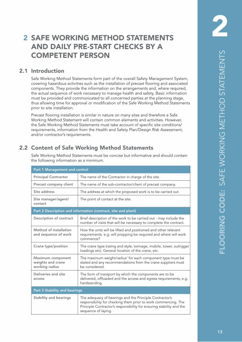
2.1 IntroductionSafe Working Method Statements form part of the overall Safety Management System, covering hazardous activities such as the installation of precast flooring and associated components. They provide the information on the arrangements and, where required, the actual sequence of work necessary to manage health and safety. Basic information must be provided and communicated to all concerned parties at the planning stage, thus allowing time for approval or modification of the Safe Working Method Statements prior to site installation.
Precast flooring installation is similar in nature on many sites and therefore a Safe Working Method Statement will contain common elements and activities. However, the Safe Working Method Statements must take account of specific site conditions/requirements, information from the Health and Safety Plan/Design Risk Assessment, and/or contractor’s requirements.
2.2 Content of Safe Working Method StatementsSafe Working Method Statements must be concise but informative and should contain the following information as a minimum.
Part 1 Management and control
Principal Contractor The name of the Contractor in charge of the site.
Precast company client The name of the sub-contractor/client of precast company.
Site address The address at which the proposed work is to be carried out.
Site manager/agent/contact
The point of contact at the site.
Part 2 Description and information (contract, site and plant)
Description of contract Brief description of the work to be carried out - may include the number of visits that will be necessary to complete the contract.
Method of installation and sequence of work
How the units will be lifted and positioned and other relevant requirements. e.g. will propping be required and where will work commence?
Crane type/position The crane type (rating and style, tonnage, mobile, tower, outrigger loadings etc). General location of the crane, etc.
Maximum component weights and crane working radius
The maximum weight/radius’ for each component type must be stated and any recommendations from the crane suppliers must be considered.
Deliveries and site access
The form of transport by which the components are to be delivered, offloaded and the access and egress requirements, e.g. hardstanding.
Part 3 Stability and bearings
Stability and bearings The adequacy of bearings and the Principle Contractor’s responsibility for checking them prior to work commencing. The Principle Contractor’s responsibility for ensuring stability and the sequence of laying.

14
Part 4 Personnel
Foreman The name if known or a statement allowing the Foreman to make himself known on arrival at site.
Slinger/Signaller, (Banksman) Installer
Statement to confirm the competence and training of Slinger/Signaller and Installers who will be involved in the installation.
Other site operations/third parties
Where co-operation and coordination with other site operations/third parties is required, this must be stated
Part 5 Health and safety management and control measures
Personal protective equipment
General statement showing that all Operatives and Installers will comply with current/site requirements.
Access to work area A of access and the Contractor’s responsibility to supply. The use of scaffolding, temporary access, etc.
Positioning of components
Standard and extraordinary methods of positioning.
Working at heights Statement regarding the provision of handrails and other means of protection.
Leading edge protection The use of fall prevention/arrest equipment, e.g. safety nets/airbags. Means of rescue from the fallen position.
Welfare facilities Provision of facilities, e.g. first aid and toilets.
Part 6 Amendments and additional information
Amendments to the Method Statement
Should any part of this Method Statement require amendment or alteration, this must be notified for agreement by all relevant parties prior to it being enforced.
2.3 Communication of the Safe Working Method StatementThe Safe Working Method Statement must be sent to the Contractor for inclusion in the Health and Safety Plan. Where changes are made these must be recorded and the appropriate amended copy sent to the Contractor. The current Safe Working Method Statement must be supplied with the Working Drawings for the installation crew to use during the installation phase. The Foreman must monitor the adequacy of the Safe Working Method Statement. Any variations are to be reviewed/approved and recorded following liaison with the Company and the Contractor.
2.4 Additions to the Safe Working Method StatementThe Safe Working Method Statement may be supplemented by attaching and/or referring to other documents, for example:
Company site safety booklets.Company procedures, for example, those regarding handling and storage.Crane Planning Schedule and Lift Plan.Company representative reports.Risk assessments.Addendums to the Safe Working Method Statement.Specifications and certification of plant and equipment, etc. Precast Flooring Federation Code of Practice, Attendances and Information Sheets. Structural Precast Association Code of Practice, Attendances and Information Sheets. The Health and Safety Plan.
This list is not exhaustive and the level of information/inclusion will vary and depends on the nature of the contract.

FLO
OR
ING
CO
DE
: SA
FE W
OR
KIN
G M
ETH
OD
STA
TEM
EN
TS
15
2 2.5 Special considerationsInformation must be supplied by the Contractor to the Precast Company following consideration of planning, delivery and access (such as schools) and environmental aspects, and of special hazards, e.g. contaminated land, proximity hazards, etc. Information must be supplied to Precast Company Representatives and others who may be affected.
2.6 Pre-start daily checks The Precast Company must ensure that prior to any work commencing a pre-start check has been completed and signed off by a Competent Person. This covers the following areas:
Crane and lifting requirements.Work at height.Structural stability.Ground conditions.Proximity hazards.Welfare facilities.
The Precast Company should ensure that the Competent Person /Site Representative is made fully aware of the need to check and sign off the above on the day of the visit to site.
Any problems found should be reported to the Company and the Contractor’s Site Representative.
2.7 Supply only In the case of a supply-only contract, guidance should be taken from the manufacturer.

16
Page left blank intentionally
FLO
OR
ING
CO
DE
: TR
AIN
ING
AN
D C
ERTI
FIC
ATI
ON
17
3 3 TRAINING AND CERTIFICATION
3.1 IntroductionThe PFF is committed to ensuring that all Installers involved in installation activities carried out by its member companies are competent. This includes ensuring a good understanding of the objectives of this PFF Code of Practice for the safe installation of precast concrete flooring and associated components. The Company should determine the level of training an individual has achieved and should provide training, instruction and refresher training as required.
3.2 ScopeThe training that applies to Trainees, Installers, Foremen, Supervisors and Precast Designers.
3.3 ResponsibilityEmployers have a responsibility under many regulations to provide appropriate training for their employees and ensure that their sub-contractors have received the appropriate training.
Section 2 of the Health and Safety at Work Act imposes a general duty on every employer to provide as much information, instruction, training and supervision as is necessary to ensure, so far as is reasonably practicable, the health and safety at work of their employees and sub-contractors.
It is the responsibility of the Company employing the individual(s) to ensure that they have appropriate experience and training in the installation of precast concrete products, for them to carry out the tasks allocated to them and for ensuring that full records of any training provided are kept securely.
3.4 General procedureAll personnel are to be trained generally in accordance with the PFF National Precast Flooring Training Scheme or similar approved precast concrete scheme. The extent of the employee’s training will depend upon the position held within the PFF member company.
3.5 TrainingThe training of personnel at all levels is to be carried out by Competent Persons or approved training organisations (e.g. CPCS/CITB/Proskills). Courses may include those in the following list, which is not exclusive.
Site safety awareness. Manual handling. Powered cut-off saw and abrasive wheel operation.Work at height/work at height equipment. This PFF Code of Practice for the safe installation of precast concrete flooring and associated components. Slinger, Signaller. Crane Supervisor (BS 7121).Appointed Person (BS 7121).MEWP (mobile elevated work platform) scissor and boom operation.

18
Forklift/tele-handler operation. Passive fall installation.CDM regulations.Tower scaffold.
In addition it is recommended that each team of Installers has either a suitably qualified person to administer emergency aid or a fully qualified First Aider. The employer’s duty to provide first aid is set out in Regulation 3(1) of the Health and Safety (First-Aid) Regulations “An employer shall provide, or ensure that there are provided, such equipment and facilities as are adequate and appropriate in the circumstances for enabling first aid to be rendered to his employees if they are injured or become ill at work”.
Note: The need for re-training must be regularly monitored; no employee can remember everything, especially if it is not an everyday part of the individual’s work. The need for re-training is an essential requirement to satisfactorily meet the requirements of the current Regulations. Re-training requirements can be monitored by expiry dates on certificates of achievement or by periodic assessment of individuals followed by refresher training.
Training is the responsibility of the company employing the Installer and other Operatives.
3.6 Certification/competencyTrained and competent Operatives should hold the following competency cards in accordance with the construction Skills Competency Scheme (CSCS) and the Construction Plant Competency Scheme (CPCS):
CSCS Precast Concrete Installer (industry accreditation A) card.CPCS Slinger Signaller card.
Operatives who have not achieved these cards should receive appropriate training and carry out the following NVQs, which will enable them to achieve the appropriate competency card:
NVQ in Precast Concrete Installation.NVQ in Slinger Signalling.
FLO
OR
ING
CO
DE
: D
ESIG
N C
ON
SID
ERA
TIO
NS
19
4 4 DESIGN CONSIDERATIONS
Installing precast concrete floors is a high-risk activity, which usually involves Operatives and Installers working at heights and the use of cranes. To assist Engineers, Designers, Contractors and CDM co-ordinator in meeting the requirements of the CDM, the following detailed information is provided to assist in co-ordinating designs to achieve safe installation. In the text that follows the Precast Designer is not the Building Designer
4.1 The existing environmentThe following aspects should be investigated; as part of the planning procedure
The sizes and weights of the components will determine the method of off-loading and placing the units. The precast units are usually delivered to site on articulated lorries; narrow roads or restricted access may necessitate the use of rigid lorries. Pedestrian and traffic management measures need to be considered, especially if the delivery lorries are off-loaded from the public highway. In this case the Contractor must ensure that any actions taken comply with the Roads and Streetworks Act. The Contractor should consider the Traffic Management Plan, other trades and deliveries, and plan adequate arrangements for offloading positions and fall protection equipment around vehicles. Access to the work area must be provided for cranes and lorries. An adequate design for hardstanding must be provided to safely support the loads imposed by the crane’s outriggers. Excavations, underground services, drains and basements are a hazard and strengthening may be required. The presence of power lines, railway tracks, trees or overhead structural obstructions may hinder the operation of cranes. On restricted sites it may be necessary for loads to be lifted over adjacent land and buildings. In these circumstances, permission must be gained to operate within the airspace of third parties in conjunction of a full risk assessment. All site restrictions and partial or full evacuations must be planned and agreed in advance.
4.2 Design and planningThe Regulations require that a designer’s competence has to be considered in the light of health and safety. Members of the PFF can demonstrate their experience and competence in the design and manufacture of precast flooring.
Particular attention must be given where units may need to be tilted or twisted into position (onto ledger angles or similar). The Building Designer and Precast Designer must assess the suitability and adequacy of supports. Careful consideration must be given to ensure that there is sufficient clearance to place the unit whilst still achieving the minimum end bearing required when the unit is in its final position.
To assist the Precast Designer, the following information should be provided at Tender Stage:
Pre-tender stage Health and Safety Plan.Design loads including finishes and imposed loads. Drawings showing the supporting structure for the precast units and direction of span.Phasing or sequencing of the works.Site and services plan.
20
4.2.1 Information following orderWhen an order is placed for the precast concrete units, the Contractor should provide the Precast Flooring Company with the following information:
Any relevant amendments to the Health and Safety Plan. Fully dimensioned ‘Construction Issue’ drawings, detailing the supporting structure for the floors and any other aspects that may affect the floor design and installation.Loadings, including type and location of partitions, types of finish, etc.Position and sizes of all holes, notches or rebates required in the flooring.Site and services plan (if not provided at tender stage).Provisional sequencing and programme dates. Where working in the vicinity of rail tracks, underground railway lines, or energy supply structures such as power cables, all permissions that are required from the owners or controllers of the relevant infrastructure are to be given in advance, along with any special instructions for the safe installation of the works.Any pertinent ground conditions e.g. access roads, crane hardstandings.
4.2.2 Stability of the structure
Designers must take into account the stability of the structure during the installation of precast components:
Consideration should be given at the planning stage to allow for the removal, prior to the installation of the components, of overhead obstructions, such as purlins, bracings or main beams (where spans change at the level above) that are likely to foul or hinder the crane boom or suspended load. Precast components are heavy. Bearings must be adequate and be robust enough to withstand normal unit fixing operations including landing and barring. Lintels or steel beams must be securely fixed and have adequate safe bearing at each end to avoid overturning, excessive deflection, or collapse when the precast units are placed. Consideration must be given to the unequal loading of unrestrained walls, lintels or steel beams when precast units are being placed. The practice of installing precast units onto temporary bearings must be avoided wherever possible. In cases where the use of temporary bearings is unavoidable they must be designed and installed by a Competent Person (provided by the Contractor).
4.3 Construction phase The installation of precast concrete units should be undertaken only by competent† Precast Installers with knowledge of the product. Members of the PFF only employ Precast Installers who are trained, competent and experienced in this work.
The Contractor must ensure that the PFF Standard Health, Safety and Welfare Attendances have been provided.
Installing precast concrete floors is a high-risk operation and should not be undertaken without the provision of a job-specific method statement and risk assessments, which should address some or all of the following activities:
Slips, trips and falls.Manual handling.Working at heights with risk of personnel/objects falling.Working with cranes.Handling or cutting concrete products. Working with wet concrete/mortar.
† Employers are required by law to ensure the competence of their employees and to provide training and instruction as necessary. CDM 2007 places duties on Contractors and Principal Contractors to ensure that workers are competent and to provide training where necessary.
FLO
OR
ING
CO
DE
: D
ESIG
N C
ON
SID
ERA
TIO
NS
21
4The Contractor must ensure that other trades and the public are kept out of the working area covered by cranes used for installing the precast units.
A major consideration for the Building Designer and Contractor should be the stability of the structure during the installation of the precast concrete units. Time must be allowed for masonry mortar to mature sufficiently to achieve adequate strength and stiffness (special consideration must be given to retarded mortar).
The Building Designer must give consideration to the provision of adequate wall thickness, particularly where shared bearings occur on lightweight masonry blocks.
The Building Designer and the Precast Designer must give consideration to the proposed sequence of construction and the effects of any temporary removal of parts of the structure to facilitate the safe installation of the precast units.
A period of curing time in accordance with the manufacturers’ recommendations should be allowed for a grouted floor to mature prior to loading out with materials, which should not exceed the load for which the floor has been designed. Advice and approval should be sought from the Company prior to the storage of unfixed materials on the floors by following trades.††
4.4 Lifting, placing and safe handling of unitsInstallation of precast flooring components is acknowledged to be a potentially high risk activity, as it involves the use of heavy plant, cranes and personnel working at height. This Code of Practice is, therefore, used as the basis for the training of Installers, Foremen and supervisors to ensure that all have the skills and competence to carry out their roles in a safe manner. This training is predominantly carried out via the training programme developed jointly between the PFF and Proskills.
As a prime consideration at the design stage, the Building Designer and the Company must pay attention to the on-site practices of handling precast units and their installation sequence.
Areas of precast units, both collectively and individually, must be so designed and detailed as to allow for adequate and safe handling, including safe means of removing lifting tackle after units have been placed.
Particular attention must be given where units may need to be tilted or twisted into position (ledger angles or similar). The Building Designer and Precast Designer must assess the suitability and adequacy of supports. Careful consideration must be given to ensure that there is sufficient clearance to place the unit whilst still achieving the minimum end bearing required when the unit is in its final position.
The Building Designer must ensure that all working drawings and specifications convey any special design requirements to the Installer, such as special fixing techniques or sequence of work, or temporary measures, e.g. braces, props. This information should be incorporated onto the Installer’s drawings by the Precast Designer.
Cantilevers do not usually present a problem as long as they are installed in accordance with the manufacturers instruction drawing. However, if units are to be installed to a cantilevered area of flooring, then the design, and working drawings, must pay attention to counterbalances, and the sequence in which these are to be installed. Any propping that may be necessary during construction must also be clearly indicated on the installation drawings (including at what stage in the installation process) and must be designed and installed by Competent Persons provided by the Contractor.
The cantilever end of any precast member must also be distinctly marked on the unit to avoid incorrect fixing.
†† In the case of conventional grouts, a minimum of 72 hours curing time should be allowed.
22
4.5 Installation of precast concrete flooring onto steelwork The following should be considered when installing onto steelwork:
All steelwork must be fully secured prior to installing any flooring units. The steelwork shall be designed to resist lateral torsional buckling during the construction phase. This can occur when only one side of the beam is loaded out. The minimum bearing lengths in accordance with the recommendations set out in the relevant design standards must be met at all times. To allow for manufacturing and construction tolerances it is recommended that the minimum bearing length provided is 75 mm. Where flooring units are to be installed on shelf angles within beams or within a slim floor system, the ends should be suitably treated to facilitate the safe installation. This can be achieved via notched ends or sloping ends. The length of the units should be designed to allow a 25 m clearance gap between the end of the unit and the supporting steelwork. Where shear studs for composite action or progressive collapse requirements are provided then the bearing length shall be adjusted accordingly. Temporary bracing to the steel frame should be considered to account for the lack of floor diaphragm action whilst the infill concrete between the units and at the bearing ends is being placed with adequate time allowed for it to cure before removing it. The bearing surfaces should be clean, level and free of debris.
4.6 Installation of precast concrete floors onto masonryThe following good practice applies to all types of masonry used in construction of cavity walls:
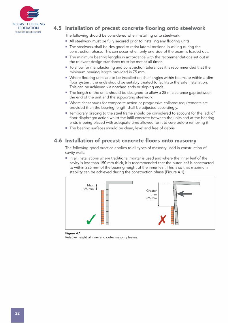
In all installations where traditional mortar is used and where the inner leaf of the cavity is less than 190 mm thick, it is recommended that the outer leaf is constructed to within 225 mm of the bearing height of the inner leaf. This is so that maximum stability can be achieved during the construction phase (Figure 4.1).
Greaterthan
225 mm
Max.225 mm
Figure 4.1Relative height of inner and outer masonry leaves.
FLO
OR
ING
CO
DE
: D
ESIG
N C
ON
SID
ERA
TIO
NS
23
4 The guidance notes covered in Figures 4.2 to 4.5 regarding lintels and steelwork should also be observed. Where the inner leaf is constructed from a minimum 140 mm thick, thin-joint masonry systems:*
The strength of the blockwork and the overall temporary stability must be checked by the Engineer who is responsible for the overall project. A maximum of 2 storeys is constructed at any one time before the outer leaf is installed, with a maximum of 4 storeys overall. The height of the blockwork is no greater than 2.7 m for each storey. Generally, unrestrained walls should be limited to a maximum length of 6 m.
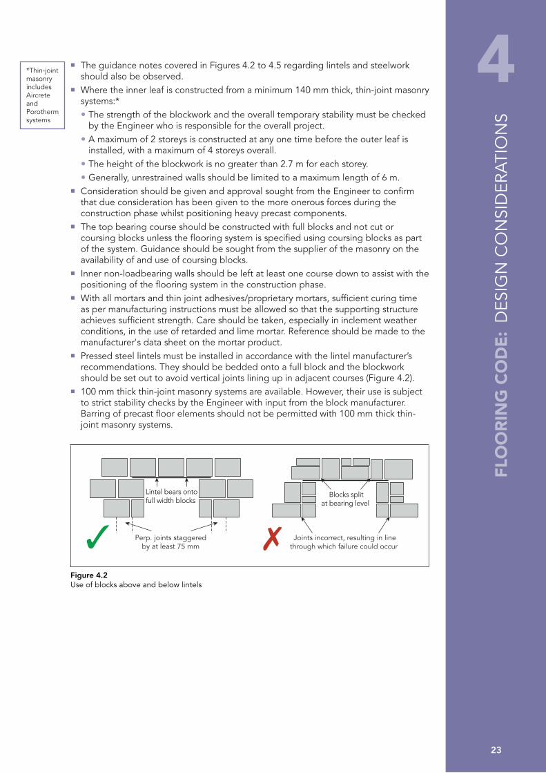
Consideration should be given and approval sought from the Engineer to confirm that due consideration has been given to the more onerous forces during the construction phase whilst positioning heavy precast components. The top bearing course should be constructed with full blocks and not cut or coursing blocks unless the flooring system is specified using coursing blocks as part of the system. Guidance should be sought from the supplier of the masonry on the availability of and use of coursing blocks. Inner non-loadbearing walls should be left at least one course down to assist with the positioning of the flooring system in the construction phase. With all mortars and thin joint adhesives/proprietary mortars, sufficient curing time as per manufacturing instructions must be allowed so that the supporting structure achieves sufficient strength. Care should be taken, especially in inclement weather conditions, in the use of retarded and lime mortar. Reference should be made to the manufacturer's data sheet on the mortar product. Pressed steel lintels must be installed in accordance with the lintel manufacturer’s recommendations. They should be bedded onto a full block and the blockwork should be set out to avoid vertical joints lining up in adjacent courses (Figure 4.2). 100 mm thick thin-joint masonry systems are available. However, their use is subject to strict stability checks by the Engineer with input from the block manufacturer. Barring of precast floor elements should not be permitted with 100 mm thick thin-joint masonry systems.
Perp. joints staggeredby at least 75 mm
Lintel bears ontofull width blocks
Joints incorrect, resulting in linethrough which failure could occur
Blocks splitat bearing level
Figure 4.2Use of blocks above and below lintels
*Thin-joint masonry includes Aircrete and Porotherm systems

24
Pressed steel lintels over openings of 900 mm or above should be pre-propped to prevent the lintel from deflecting and rotating during the construction phase (Figure 4.3). This requirement is in line with the steel lintel manufacturer’s guidelines. This propping is not necessarily required for standard concrete lintels.
Lintels should be designed with the construction phase loading in mind, as this type of lintel does not achieve full load capability until construction is complete.
Prop inner leaf
Figure 4.3Propping of steel lintels
Steel section lintels should be firmly secured by the contractor to padstones set onto the blockwork. Ties down the wall should be used in vulnerable conditions such as isolated piers. Where it will be loaded unequally, the lintel may require additional temporary support to prevent rotation during the installation of precast floor units (Figure 4.4).
Figure 4.4Fixing steel to padstones set on blockwork
Isolated steels must be fixed and temporary propping should also be incorporated where the ‘fixed’ steel beams are likely to torsionally deflect during installation of the precast floor units (Figure 4.5) . Fixings should not hinder the installation and the design should be checked for temporary loading to avoid torsional collapse during the construction phase.
Fixed and propped Rotating due to lack of torsional restraint
Figure 4.5Fixing of isolated steels

FLO
OR
ING
CO
DE
: D
ESIG
N C
ON
SID
ERA
TIO
NS
25
4 All wall ties must be in place and installed in accordance with the relevant standards or code. Narrow sections of walls (less than 900 mm) or piers should be given special consideration as these can be weak points during the construction phase. The Building Designer may need to consider additional temporary support. The bearing surface should be clean, level and free from mortar snots. Where an internal loadbearing wall intersects with other loadbearing walls, the joints must be fully bonded or tied in. Before installing floors on loadbearing walls less than190 mm wide, temporary propping or other means of bearing enhancement should be employed, designed and installed by Competent Persons (other than the flooring Installer). Timber runners should be positioned approximately 5 mm below bearing level and in tight contact with each side of the wall to provide full lateral support (Figure 4.6). The propping arrangement and timber runners should also be designed to increase bearing width and carry the floor reaction in the event of a bearing failure.
Lateral restraint to top of wall
Timber runner
Figure 4.6Support for wall less than 190 mm wide
When installing floors on loadbearing walls less than 190 mm wide (Figure 4.7): Bearing plate to be laid on a mortar bed by Main Contractor before installation of precast slabs. Blockwork to be built 20 mm lower at bearing plate locations to allow for mortar bed and bearing plate depth. Flooring units must be installed on alternate bays. When landing on a bearing plate, installer must ensure that the slab is landed on centre of bearing plate. Shorter span to be installed first.
20 mm
140 –190 mm
Blockwork to be laid 20 mm lower
Bearing plate to be laid on 20 mm mortar bed
Typical section detail Bearing plate detailwhere slabs share a 140 mm wall
2 rows of bottom lugs per plate, staggered at 150 mm
SectionPlan
150 mm
50 mm
200 mm
200 mm
150 mm
1000 mm
500 mm500 mm
500 mm500 mm
100 mm
100 mm
Figure 4.7Fixing floor to wall less than 190 mm wide
26
4.6.1 General notes for the Building DesignerCement mortars – allow 3 to 7 days for masonry mortar to cure before loading out
Lime and retarded mortars – always check curing times with manufacturer or supplier.
With all mortars and thin joint adhesives/proprietary mortars, sufficient curing time as per manufacturing instructions must be allowed so that the supporting structure achieves sufficient strength. Care should be taken, especially in inclement weather conditions, in the use of retarded and lime mortar. Reference should be made to the manufacturer's data sheet on the mortar product.
4.7 Imposed loads during the construction phaseIn addition to the self-weight of the floor units, other loads may be imposed during the installation operation. These loads must be anticipated at the design stage and be considered when selecting unit types and layouts.
With beam and block systems, the weight of blocks being loaded for installation must be assessed, and any prohibitions, or special requirements to accommodate such loads, must be clearly indicated by the Precast Designer.
When screeds or structural toppings are required, the imposed loads must be anticipated by both the Building Designer and the Precast Designer and special provisions clearly noted.
Design loadings for the floor are stated on the drawings and must not be exceeded during the construction works. Approval should be sought from the Company prior to the storage by following trades of unfixed materials on floors.
4.8 Stability of supporting structure during installationThe stability of the supporting structures must not be adversely affected by the installation of precast flooring and components, including temporary stacking on the floors.
If the removal of any structural member is necessary to facilitate the installation, structural stability must be maintained and the Building Designer must liaise with relevant Engineers, Contractors and Sub-contractors. The Contractor is responsible for the removal and replacement operations, by way of an Attendance, to ensure the safe installation of the precast units.
Where it can be anticipated that stability will not be guaranteed, as in the case of temporarily propped or jacked floors, a safe system of work must be developed to keep the structure within the safe limits allowable.
The following must also be considered: All temporary works must have been correctly designed and installed by Competent Persons provided by the Contractor, prior to the Precast Company arriving on site. When designing bearings, consideration must be given to the standard method of fixing precast concrete components, particularly the method of final alignment. Construction loading arrangements/forces may be more onerous than the final working condition. The Building Designer must take into account manufacturing and construction tolerances to ensure minimum bearings are achieved. The Building Designer must undertake an assessment of the risks likely to occur during installation of the precast flooring/component and any potential instability issues relating to the supporting structure. Advice and approval may be sought from the Precast Designer on these matters.
FLO
OR
ING
CO
DE
: D
ESIG
N C
ON
SID
ERA
TIO
NS
27
4 4.8.1 Handrails to stairs and landings It is considered good practice for the Building Designer to specify a type of handrail and the method of fixing the handrail to a stair flight and landing before the flight or landing is lifted into its final position.
The installation of the handrail will therefore be carried out from a safer position, i.e. ground level on site, avoiding the need to work at height, and the stairs can then be immediately used for safe access to different levels. However, it is recognised that this is not always achievable. Where other methods are used they must mitigate risks and achieve a safe system of work.
The Contractor should undertake careful planning at pre-contract and design stage. The Contractor should liaise with the Precast Installer/Precast Designer and consider the following points to ensure that the specified method is practical and agree arrangements with the other parties:
Can the stairs and landings be safely lowered into position with the handrails attached? Can the handrails be adequately secured for safe lifting into position? Will the handrails on the installed units clash with any subsequent fall protection required at higher levels? Contractor to arrange work so that it is carried out to the agreed sequence of installation. Contractor to coordinate other trades to be in attendance as required, i.e. Scaffolder. Position of fixing and design of fixing for handrails to be agreed with the Precast Designer. Contractor to ensure that, after filling of any holes, the concrete finish has been agreed with the appropriate Building Designer/Specifier.
4.9 The Health and Safety File The Precast Company will provide ‘as installed’ drawings at completion of the installation, showing any changes from the original floor layout. Thereafter, the Contractor will be responsible for recording departures from the as installed drawings. The flooring layout drawings will detail the loads for which the floors have been designed. Care should be exercised to ensure that during both the Construction Phase and during the life of the building, the design loads are not exceeded and that further holes or chases are not made in the flooring without reference to the Company. On demolition, advice and approval should be sought from a Competent Person, with access to the Health and Safety File.
4.10 Other construction methodsThe PFF acknowledges that there are many other Modern Methods of Construction that are not considered as part of this Code of Practice. Advice relating to any other forms of construction not covered can be obtained from the PFF Technical Committee.

28
Page left blank intentionally

FLO
OR
ING
CO
DE
: C
ON
TRA
CTO
R’S
RESP
ON
SIB
ILIT
IES
29
5 5 CONTRACTOR’S RESPONSIBILITIES
5.1 AttendancesThe flooring sub-contractor will provide the Contractor with a copy of the PFF Health, Safety and Welfare Attendances (which form Appendix A to this Code of Practice), attached to the Company’s quotation. These, together with any additional specific requirements necessitated by the nature of the site or contract works, are to be provided by the Contractor.
The Contractor must also maintain and upgrade these attendance items to compensate for deterioration through usage and weather.
5.2 Management of construction worksThe Contractor must familiarise themselves with the safety aspects of precast concrete installation works by reading this Code of Practice and taking note of issues raised by the Company Representative during the pre-start site visit.
The Contractor is responsible for ensuring that guidance within this Code of Practice is incorporated into works by other trades and, where necessary, the guidance of the Building Designer and other specialist suppliers/sub-contractors is incorporated into the works.
5.3 Prevention of damage to precast unitsThe Contractor is deemed to accept responsibility for the protection of precast units from the time when the physical installation of the sub-contract works, or any section thereof, has been completed, unless otherwise agreed.
Any grouting should be carried out in accordance with Section 12.3.2. At the time when the precast flooring installers leave the site, the grouting (where applicable) will generally be in an ‘uncured’ condition. Whilst the grout is not always structural, it is recommended that a minimum curing period of 72 hours should be allowed. During this time the floor may require weather protection, the provision of such protection being the responsibility of the Contractor.
In most cases, damage sustained to flooring units is caused by impact during the progression of following trades. Other damage that frequently occurs is caused by cutting and drilling the precast concrete units; this must not happen without first consulting the Company.
5.4 Handrailing to precast stair unitsThe Contractor is responsible for the upkeep, adaptation and final removal of the handrailing to ensure that protection is maintained for all subsequent operations.

30
Page left blank intentionally

31
FLO
OR
ING
CO
DE
: C
OM
PAN
Y RE
PRES
ENTA
TIV
E’S
ROLE
6 6 COMPANY REPRESENTATIVE’S ROLE
Prior to any installation work, the Company Representative will visit the site to identify any site-specific hazards and establish a safe system of work in agreement with the Contractor.
6.1 Agreed sequence of installationThe Company Representative will liaise with the Contractor at the site to agree the sequence in which precast flooring units are to be installed with reference to building plot numbers, floor levels, building types, grid references, etc. Should it be necessary for the installation sequence to be varied, for whatever reason, this should be implemented only after reference to the Company, Contractor and Building Designer, and after all safety requirements have been satisfied. If deemed necessary, the Safe Working Method Statement should be amended by an addendum to cover the revision agreed.
6.2 Method of liftingThe Company will provide the Appointed Person for lifting operations. Unless otherwise agreed, they will be chosen according to training, knowledge and experience. If necessary, in liaison with crane hire representatives, the Company Representative will decide upon the type of lifting plant and equipment to be employed in the installation of each specific contract, taking into account the weight of components to be lifted, the radius of lifting, and any special handling requirements.
The Contractor and the Appointed Person will discuss and advise upon the type and size of delivery lorries and craneage, in order that the Contractor will make provision for adequate access and hardstandings, or other facilities that may be required to accommodate delivery and lifting equipment.
The Appointed Person must also bring to the attention of the Contractor any factors likely to hinder the lifting operations, e.g. aerial obstructions, proximity hazards, stacked materials or earthworks, in order that a safe system of work and/or control measures can be agreed.
After reaching a decision upon the lifting arrangements, the Appointed Person should provide a record, including the agreed hardstanding positions, ground bearing pressure requirements, roadways, agreed offloading positions and any storage areas. A duplicate should be handed to the Foreman before work is commenced.
If at any time subsequent to the Company’s initial choice, the design is altered so causing component weights to vary from those originally envisaged, the Precast Designer must inform the Appointed Person who must ensure that the crane or lifting equipment is still adequate.
During the routine pre-contract visit, the Appointed Person must ensure that the site constraints observed or anticipated at the time when the crane or lifting equipment was selected, have not changed and will not change. If change has occurred, or can be anticipated, the Appointed Person must again ensure that the crane or lifting equipment is adequate. The Contractor and Building Designer must be notified of any changes.
It is the Contractor’s responsibility to ensure the provision and maintenance of suitable ground bearing conditions for the planned lifting operations.
In any instance where the crane or lifting equipment is changed from the original, the Appointed Person must be advised, and the Contractor’s Site Representative informed, of such change, in order that access, standing areas, or other measures are amended as deemed necessary. An Appointed Person will amend the lift plan accordingly and submit to the Contractor.
If the Contractor provides the craneage (i.e. tower crane) and lift planning, he must also provide an Appointed Person for the lifting operations. The company Representative
32
must provide the Contractor with all relevant information, e.g. component weights, and agree offloading positions.
6.3 Site accessThe Company must agree with the Contractor the access from the public highway onto site, including the possible need for temporary or long-term removal of any fences, walls or other obstructions. See also Appendix A, sections 1.5 and 1.6. The condition of the agreed access roads must at all times be maintained or improved by the Contractor to an acceptable standard.
Whilst making these arrangements, the locations of, and access to, stacking areas, stores, temporary buildings and lorry/trailer holding areas must be agreed.
On agreement of the provisions, a written record must be issued to the Contractor. The agreed access and other arrangements must then be incorporated into the Work Method Statement, in order that all parties will have the information readily available and to avoid misunderstandings or confusion when the floor installation commences.
Access into the building(s) as construction progresses must be agreed together with protection on and around the flooring in accordance with the requirements of the PFF Standard Health, Safety and Welfare Attendances (Appendix A), issued at tender stage. Particular attention should be paid to barriers, guardrails/handrails, toe-boards, access, lighting and similar precautions. The Company must monitor the provision of these Attendances during the period of the site works.
6.4 Attendances liaisonThe Contractor should be aware of the Company’s general requirements with regard to Attendances, having received the PFF Health, Safety and Welfare Attendances as specified in Appendix A to this Code of Practice.
The Company Representative should discuss the general requirements with the Contractor in order to agree more specific Attendances that reflect the nature of the site and the contract works.
All agreements reached between the Company Representative and the Contractor’s Site Representative must be confirmed either in writing or by inclusion on a marked-up record, copies being held by both parties to the agreement.
Prior to the precast component installation, the Contractor should ensure the suitability of bearings provided for the flooring, in accordance with the construction drawings and this Code of Practice.
6.5 Supervision of installationAn Appointed Person should attend site on the first day of installation and prior to any work being started, to carry out lift plan briefing to the Foreman and installation team, paying particular attention to any special problems or conditions relative to the Safe Working Method Statement.
Whilst on site the Company Representative should satisfy himself that the Contractor’s Attendance items have been satisfactorily provided and ensure that the Foreman is fully aware of the Contractor’s and Sub-contractor’s obligations.
On contracts of a complex nature a Company Representative should spend a greater length of time with the installation team. In certain cases, the Company Representative should oversee the complete installation.
Only where the Appointed Person has determined that the general lifting operations are basic or standard, the Appointed Person’s duties can be delegated. The person to whom those duties are delegated will then assume the duties of Crane Supervisor.
It is essential for the Company Representative to call on site at intermediate points throughout the contract, to ensure that installation is proceeding in a safe and proper manner and that all Attendances continue to be provided.

33
FLO
OR
ING
CO
DE
: FO
REM
AN
’S R
OLE
7 7 FOREMAN’S ROLE
7.1 Working to sequencePrior to the arrival of the installation team, a sequence for on-site installation must have been agreed, in the form of a Safe Working Method Statement, with records kept on site and a copy handed to the Foreman.
It is the responsibility of the Foreman to ensure adherence to the agreed sequence. In circumstances where a deviation from the sequence is unavoidable, the Foreman must seek advice and approval before altering the sequence, either by referring back to the Company, or to the Company Representative responsible for that contract.
7.2 Pre-start checksBefore commencing the installation of any precast units, the Foreman must satisfy himself that the Attendances agreed for that contract are available and of a satisfactory standard in accordance with the Safe Working Method Statement. Where possible such a pre-start check should be conducted together with the Contractor’s Site Representative.
If any item is found to be inadequate or missing, the Foreman must highlight the problem and, if necessary, delay the installation until Attendances are satisfactory. In such circumstances, the Foreman must fully acquaint his head office with the situation.
The Foreman must ensure, by inspection prior to the installation, that the bearings provided for the precast units (including those on steelwork) are visually satisfactory. It is preferable, and contractually prudent, that the Foreman should be accompanied by the Contractor’s Site Representative during these inspections. However, it is essential that the Foreman carries out these inspections, and reaches his decisions based on his inspections regardless of the presence or the absence of the Contractor’s Site Representative.
The Foreman should ensure any deviation from the provision of fall protection detailed in the Safe Working Method, is reviewed, approved and documented by the Company prior to implementation.
7.3 Supervision of installationWhere it has been determined that the general lifting operations are basic or standard, the Foreman may be delegated by the Appointed Person to assume the duties of Crane Supervisor, providing he is suitably qualified and competent. The Foreman to whom those duties are delegated will then assume the duties of Crane Supervisor.
In all cases, the Foreman is responsible for the actual installation of the precast units. On contracts where the Company Representative oversees the installation, the overall responsibility for the installation team and their actions still remains with the Foreman. The Company Representative should give instructions to the Foreman only.
The delegation of specific tasks within the team is the responsibility of the Foreman, who must be satisfied that the person to whom the task is assigned is competent to carry out that work safely.
Before placing any units the Foreman must ensure that the crane (where applicable) is operating in a safe and proper manner, and that the Crane Operator is fully aware of the nature of the work and can identify and understand the Slinger/Signaller.
Where the Foreman has concerns regarding the adequacy of the bearings and/or the structural integrity of the building, he must seek advice and instruction from the Company Representative.

34
During the course of the installation, the Foreman must check the adequacy of the bearings; any variation or deterioration, from whatever cause, must be brought to the attention of the Contractor’s Site Representative. Work must be suspended if the bearings are deemed unacceptable.
During the installation of the precast units the Foreman must ensure that correct handling and placing procedures are being adhered to, and that all aspects of the work are being executed in a safe and proper manner, in accordance with the Safe Working Method Statement and Working Drawings.
The Foreman must also check the dimensional accuracy of the individual units and the accuracy of setting out of the floor, ensuring that all units correspond with the Working Drawings.
No variations to the design or design details and no remedial works should be carried out without the prior approval of the Precast Designer and the Building Designer. No change to the construction method or sequence should occur without the prior approval of the Precast Designer, the Building Designer, the Contractor and the Company Representative.
When the installation of the floor is complete or any section of the floor which that visit covers, the Foreman together with the Contractor’s Site Representative should physically inspect the work. Should any damaged or improperly fixed components be present these should be replaced or repaired as soon as is reasonably practicable, after reference by the Foreman to his Company.
The Foreman must also coordinate and monitor other site personnel involved with the precast installation works, such as fall protection Operatives and delivery drivers.
7.4 Workmanship Units should be fixed strictly in accordance with the Working Drawings.
No ‘unspecified’ works of any type, including remedial works, should be carried out without the prior approval of the Precast Designer, the Building Designer, the Contractor and the Contractor’s Representative. If approved and carried out, it must be recorded by the Company.
The Foreman must ensure that the Work Area is kept clean and tidy, so far as this is reasonably practicable, and at the end of the working day the area should be left free of debris. Materials must be safely stacked.
After the floor is installed, the Foreman will advise the Contractor’s Site Representative that the work is completed and request an inspection prior to leaving site. During this period a checklist will be completed and a copy will be left on site.

35
8 8 TRANSPORTATION OF COMPONENTS AND ACCESS TO SITE
8.1 The stacking and making secure of loadsThe fundamental concerns when loading delivery vehicles must be to ensure an even weight distribution and load stability.
When considering the loading of precast components, it is important that the loading arrangements allow the maximum protection against damage or breaking. Cut widths or slabs that have detail, such as holes, may need to be placed at the top of the load to avoid damage during transportation.
Components must have bearers placed at correct positions along their length, in accordance with the Company’s recommendations. Where components are stacked in layers of more than one high, the bearers to each layer should line through vertically, to avoid shear planes.
When loaded, the units must be properly and adequately secured to the vehicle, to prevent movement during transit, particular attention being paid to loose items. Measures must be taken to prevent individual concrete blocks or fragments and angles or timber falling from the vehicle.
8.2 Loading sequenceFrom the point of view of safety during the installation operation, it is important that components are loaded so that unloading may be carried out in the appropriate sequence. However, this must never be at the expense of the safe transit of the complete load and therefore some double handling may be required at the point of installation.
8.3 Site accessBefore a vehicle arrives on site, the access from the highway onto and around the site should have been agreed between the Company Representative and the Contractor, taking into account the site traffic management plan. The Foreman should have checked access suitability with the Contractor’s Site Representative upon commencement of work on site.
A nominated member of the installation team should act as Signaller or Banksman to supervise and assist in the positioning of the delivery vehicle both on and off site.
Notwithstanding the above, the final acceptance of the access suitability will remain with the vehicle driver, and in these circumstances the driver must satisfy himself before entering the site that his vehicle can travel safely on the access provided.
In all cases the driver must not remove any securing ropes, chains, or tarpaulins until his vehicle is at rest in the area agreed for unloading.
8.4 Off-loadingThe Installer must ensure that the correct lifting equipment is available on site to off-load components and must also visually inspect cast-in fittings and components to ensure that no damage has occurred in transit.
Components must be unloaded in such a manner that the stability of the delivery vehicle is not adversely affected. The Installer should, when necessary, liaise with the delivery driver to ascertain the most suitable unloading sequence.
FLO
OR
ING
CO
DE
: TR
AN
SPO
RTAT
ION
OF
CO
MPO
NEN
TS A
ND
AC
CES
S TO
SIT
E

36
When components are taken straight from the vehicle to their fixing position, care must be taken to ensure that any loose packing or protective materials have been removed and that any fittings are secure.
In rare circumstances where components may have to be lifted or pass over the cab of a delivery vehicle, the Installer must ensure that the driver leaves the cab and remains in a safe position, until advised by the Foreman that the lifting operations have ended. The Company Representative should ensure that delivery drivers are equipped with necessary PPE.
Where proprietary cast-in lifting anchors are provided in the units, all anchors must be used strictly in accordance with the anchor manufacturer’s recommendations and Company procedures. Any specialist lifting equipment, e.g. grabs, must be used strictly in accordance with the manufacturer’s recommendations. Where proprietary lifting systems are not provided, choke-hitched chains or slings should be positioned between 150 mm and 300 mm in from the ends, unless specific permission has been received from the manufacturer. Lifting chains or slings should be of sufficient length so that the included angle is not greater than 900 (450 from vertical) unless otherwise agreed by the Appointed Person (Figure 8.1).
In situations where limited headroom is available the Appointed Person must ensure that the lift is planned so as to maintain a maximum of 90° at the included angle.
Special consideration may be needed for cantilever units where weight distribution is uneven. Non-standard units that do not have even weight distribution across their length require additional support whilst lifting. These should be identified by the flooring designer.
90° maximum
150 mm min. / 300 mm max.
Figure 8.1Use of slings where proprietary lifting systems are not provided
8.5 Inspection of precast concrete flooring and other components prior to offload and/or installationEvery precast floor, balcony or stair unit must be inspected before lifting from the delivery transport and/or stockpile on site for obvious signs of damage, e.g. cracking, damage around holes/notches. Where a unit is deemed to be damaged, the Foreman must telephone the Company for advice, contacting a person competent to make the decision, on what action should be taken in respect of the damaged unit.
Before removing chains, components must be measured to ensure that the correct bearing can be achieved and the Company contacted in any case when the Foreman is in doubt.
A further visual inspection must also take place after the units have been installed and before the area is handed over to the Contractor. In addition to the defects considered above, a check must also be made to ensure that all units have adequate bearing and that all areas have been sufficiently grouted. Figure 8.2
Lifting points with safety chains
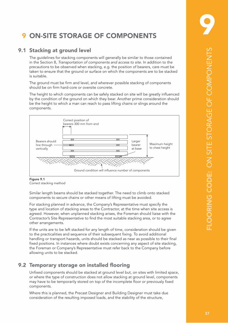
37
9 9 ON-SITE STORAGE OF COMPONENTS
9.1 Stacking at ground levelThe guidelines for stacking components will generally be similar to those contained in the Section 8, Transportation of components and access to site. In addition to the precautions to be observed when stacking, e.g. the position of bearers, care must be taken to ensure that the ground or surface on which the components are to be stacked is suitable.
The ground must be firm and level, and wherever possible stacking of components should be on firm hard-core or oversite concrete.
The height to which components can be safely stacked on site will be greatly influenced by the condition of the ground on which they bear. Another prime consideration should be the height to which a man can reach to pass lifting chains or slings around the components.
Bearers should line through vertically
Maximum heightto chest height
Correct position ofbearers 300 mm from end
Ground condition will influence number of components
Largerbearerat base
Figure 9.1Correct stacking method
Similar length beams should be stacked together. The need to climb onto stacked components to secure chains or other means of lifting must be avoided.
For stacking planned in advance, the Company’s Representative must specify the type and location of stacking areas to the Contractor, at the time when site access is agreed. However, when unplanned stacking arises, the Foreman should liaise with the Contractor’s Site Representative to find the most suitable stacking area, or to agree other arrangements.
If the units are to be left stacked for any length of time, consideration should be given to the practicalities and sequence of their subsequent fixing. To avoid additional handling or transport hazards, units should be stacked as near as possible to their final fixed positions. In instances where doubt exists concerning any aspect of site stacking, the Foreman or Company’s Representative must refer back to the Company before allowing units to be stacked.
9.2 Temporary storage on installed flooringUnfixed components should be stacked at ground level but, on sites with limited space, or where the type of construction does not allow stacking at ground level, components may have to be temporarily stored on top of the incomplete floor or previously fixed components.
Where this is planned, the Precast Designer and Building Designer must take due consideration of the resulting imposed loads, and the stability of the structure,
FLO
OR
ING
CO
DE
: O
N S
ITE
STO
RAG
E O
F C
OM
PON
ENTS
38
especially lintels over openings. This action will be the subject of a Design Risk Assessment and Safe Working Method Statement prior to the commencement on site by the Company.
When unplanned storage occurs, the Foreman will liaise with the Contractor’s Site Representative, the Building Designer and the Precast Designer to agree an acceptable method.
In most circumstances the following measures should be considered to ensure minimum risk:
All loads should be lowered gently onto the floor, avoiding sudden impact, which may cause damage. When components are being stacked, bearers should run at 90° to the span of the floor on which they bear. Wherever possible, bearers should be placed above the wall or bearing supporting the precast flooring. Where a number of components are to be stored, refer to the Engineer for specific instructions. The Foreman should liaise with the Contractor’s Site Representative to ensure that no further loads are placed on floors already carrying other stacked components, e.g. bricks, blocks, other building materials or plant. To avoid damage, cut width or components that have detail such as holes should be placed at the top of stacked components or separately. Where infill blocks are not loaded on pallets they should be stacked on sheet plywood or similar material to prevent the fracture of fixed infill blocks. Also, infill blocks should not be stacked at mid-span but should be placed above the bearing walls, or similar, to ensure good load distribution. Units must not be stacked on partially constructed steel frames or structures or in areas that allow for displacement through accidental contact with the units.

39
10 10 SAFE USE OF CRANES, FORK LIFTS AND OTHER LIFTING EQUIPMENT
10.1 IntroductionThe Lifting Operations and Lifting Equipment Regulations (LOLER) require that lifting equipment provided for use at work is:
Strong, stable and marked with safe working loads.Correctly used.Used safely. Subject to on-going review.
The Regulations also require that lifting operations are: Planned, supervised and carried out safely by people who are competent.Controlled, i.e. all documents are checked and in order.
The Lifting Operations and Lifting Equipment Regulations 1998 Approved Code of Practice (ACoP) refer to BS 7121 Code of Practice for the safe use of cranes: Part 1 General and Part 3 Mobile cranes as the standard that should be adopted. It is in the interests of all parties involved in lifting operations that they are carried out efficiently and safely. The ACoP ensures that everyone involved in a lifting operation is aware of their responsibilities. This Precast Flooring Federation Code of Practice covers all the work involved in handling and positioning concrete products.
10.2 Management of the lifting operationDuring preliminary site visit(s) a safe system of work must be established by the Appointed Person, and recorded in the form of a Safe Working Method Statement. This must be followed for every lifting operation or a group of repetitive operations. This principle applies to all lifting operations.
Lifting equipment must be positioned or installed in such a way as to reduce, to as low a level as is reasonably practicable, the risk of the equipment or load striking a person and the risk of the load drifting, falling freely or being released unintentionally.
The safe system of work for crane operations must include the following: Planning of the operation including risk assessments must be carried out by a Competent Person. This should include ensuring that the lifting operation is adequately supervised and carried out in a safe manner. Selection, provision and use of suitable crane(s) and equipment. Ground conditions must be examined, including access, working and adjacent areas. Particular attention must be paid to:
Trenches, cellars and basements.Underground services.Ramps, slopes, edges and uneven ground.
Positioning of the lifting equipment to ensure the safety of those working with the equipment and those who may be affected by its operation. This includes eliminating trapping points or preventing access to them by persons. Verifying that crane(s) and ancillary equipment are properly inspected and certificated. Provision of properly trained and Competent Personnel with the necessary authority who have been made aware of their relevant responsibilities under the Health and Safety at Work Act. BS 7121 defines roles and responsibilities.
FLO
OR
ING
CO
DE
: SA
FE U
SE O
F LI
FTIN
G E
QU
IPM
ENT
40
Effective communications between all relevant parties. Preventing unauthorised use or movement of the crane. The safety of persons not involved in the lifting operation, including eliminating the need to lift the load over people.
The lifting operation must be taken to include any necessary preparation, as well as installation and dismantling of the crane(s).
The Safe Working Method Statement must be effectively communicated to all parties concerned.
10.3 Control of the lifting operation To ensure the implementation of the safe system of work, one person must be appointed to have overall control and responsibility of the lifting operation and to act on behalf of the Company.
The appointment of this person does not remove any legal responsibility from the Employing Organisation but enables them to use his expertise to better fulfil their responsibilities. The person appointed may have other duties and need not be an employee of the Company.
The Appointed Person must have adequate training and experience to enable these duties to be carried out competently.
The duties of Appointed Persons for crane operations can vary in accordance with the complexity of the operation. The duties for a ‘basic lift’ are considerably fewer and less demanding than for a lift at a hazardous location. Hence, an Appointed Person employed for a ‘basic lift’ may not be suitably trained or experienced for a more complicated operation. Therefore, ‘complex lifts’ should be planned and supervised by a suitably competent Appointed Person in consultation with the crane hire company and the Contractor. The types of lift are defined below.
Basic liftLifting operation where the weight of the load(s) can be simply established, and there are no significant hazards within the area of the operation or on the access route to the working area. Intermediate lift (also known as a Standard lift)Lifting operation where there are significant hazards, either within the working area of the crane or on the access route to the working area. Complex liftLifting operation which includes cranes used for lifting complex loads, the lifting of persons, lifting the load with two or more cranes or when the lifting operation is at a location with exceptional hazards. Note: An example of a location with exceptional hazards is a chemical plant.
Where the Appointed Person has determined that the General Lifting Operations are basic or intermediate, the duties, but not the responsibility for the lifting operation, can be delegated to a Competent Person who will then assume the duties of the Crane Supervisor.
The Crane Supervisor, having been delegated as being in control, will have the authority to stop the lifting operation if it is considered to be unsafe to continue and refer to the Appointed Person.
Where the Contractor provides the crane and the services of an Appointed Person, they must provide details of the lifting equipment that will be used, including configuration, duty charts, location relative to installation area, etc. The Company Representative will provide details to the Contractor’s Appointed Person of the weight of the products to be installed and agree an off-loading position. The Appointed Person and Crane Supervisor must be identified in the Method Statement. Prior to commencement of the works, the Contractor’s Site Representative must demonstrate to the Installer that the lifting operation has been adequately planned.

FLO
OR
ING
CO
DE
: SA
FE U
SE O
F LI
FTIN
G E
QU
IPM
ENT
41
10 10.4 Crane hire or contract lift
10.4.1 GeneralGiven the wide variety of contractual arrangements used in the construction industry, it is important to ensure that the planning, organisation, control and management of lifting operations is not compromised. In general, any organisation requiring a load to be moved by crane, which does not have its own craneage, has two basic options: hiring a crane (Hired Crane) or employing a contractor to carry out the lifting operation (Contract Lift). The difference between the two options is summarised in Figure 10.1
Employing OrganisationThe organisation requiring the load to be moved
Hired Crane(Hired and managed)
Contracted Lift(Fully contracted)
The Employing Organisation
should:
The Crane Owner has duty to:
The EmployingOrganisation
should specify:
The Contractor is responsible
for:
� Carry out all work in accordance with BS 7121
� Supply the Appointed Person
� Plan the lift and operate a safe system of working
� Ensure that a crane hired is of suitable type and capacity
� Check the credentials of the hire company and certification supplied
� Provide a crane that is properly maintained, tested and certified
� Provide a competent driver
� That all work is to be undertaken in accordance with BS 7121
� That the Contractor is to supply the Appointed Person
� Information and/or services to be provided to the Contractor by the Employing Organisation
� Supplying the Appointed Person
� Planning the lift and operation of a safe system of work
� Organisation and control of the lifting operation
Figure 10.1Organisation of hired/contracted lifting operations
If an individual or organisation does not have the expertise in lifting operations they should not hire cranes but should opt instead for a contract lift. Before entering into a contract, Employing Organisations should satisfy themselves that the Contractor has the necessary competence to carry out the work.
Note: Responsibilities for insurance of the crane, personnel, the load and third parties may also need to be clarified.
10.4.2 Employing Organisation’s duties when hiring cranesWhen a crane is hired out together with an Operator to the Employing Organisation, the crane owner should provide a Competent Operator and a crane that is properly maintained, inspected and tested in accordance with BS 7121-2, and has a current
42
report of thorough examination. The Employing organisation retains the responsibility for nominating the Appointed Person and for following the recommendations given in the BS 7121 series. Despite any advice the Crane Owner might have offered concerning the selection of a particular crane or any other relevant matter, for example clearances or ground conditions, the responsibility for ensuring that the crane is of a suitable type, size and capacity for the task being undertaken and for planning the operation remains with the Employing Organisation. Therefore if an individual or organisation does not have expertise in lifting operations, they should not hire cranes but should opt for a contract lift.
10.4.3 Contract lifting operationsThe Employing Organisation may enter into a contract with a Contractor who undertakes work on their behalf.
The parties to the contract should ensure that:All work is carried out in accordance with BS 7121 series. The Contractor appoints a competent Appointed Person to the satisfaction of the Employing Organisation. All information or services provided by the Employing Organisation to facilitate compliance with the BS 7121 series are notified to the Contractor in writing.
The contractor should carry out lifting operations in accordance with the BS 7121 series. The Contractor should be given full authority by the Employing Organisation to work in accordance with the BS 7121 series including, where appropriate, authority to control and instruct the Employing Organisation’s personnel
Before entering into a contract, Employing Organisations should ensure that the Contractor has the necessary competence to carry out the work in accordance with the BS 7121 series.
10.5 Planning the lifting operation
10.5.1 GeneralAll lifting operations should be planned to ensure that they are carried out safely and that all foreseeable risks have been taken into account. Planning should be carried out by an Appointed Person who has the appropriate knowledge for the lift being undertaken. In cases of repetitive or routine basic lifting operations, this planning might only be necessary in the first instance, with periodic reviews to ensure that no factors have changed.
Planning of the lifting operation should take into account:The load, its characteristics and the method of lifting. The selection of a suitable crane(s) appropriate to the operation ensuring that adequate clearances are maintained between the load(s) and the crane structure. The selection of accessories for lifting/lifting attachments, their weight to be taken into account when assessing the load on the crane(s).The position of the crane(s) and of the load before, during and after the operation. The site of the operation including proximity hazards, space availability and suitability of the ground or foundations.Any necessary installation and dismantling of the crane(s). The environmental conditions that exist or might occur at the site of the operation or the effect of the load on the crane.
FLO
OR
ING
CO
DE
: SA
FE U
SE O
F LI
FTIN
G E
QU
IPM
ENT
43
10 10.5.2 Risk assessmentAs part of the planning process a risk assessment should be carried out by the Appointed Person to identify the hazards associated with the proposed lifting operation. The assessment should evaluate the risks involved and the nature and extent of any measures required to mitigate those risks. The assessment should also take into consideration hazards identified by the overall site risk assessments.
The results of the risk assessment should be recorded in writing and used in the preparation of the method statement for that site.
10.5.3 Method StatementsOnce the risk assessment has been carried out, the Appointed Person should ensure that a full Method Statement is prepared, detailing the safe system of work for the lifting operation and including the risk assessment.
When necessary, the Appointed Person should consult with others with specialized knowledge and experience.
The Method Statement should include: The tasks to be achieved, together with the configuration of the crane at the end of each day’s work. Details of the steps to be taken to eliminate danger to personnel not involved in the lifting operation, and where necessary, prevent their entry into danger zones, e.g. by organizing for road closures if necessary. The requirement for pre-use checks to be completed. A clear statement of the allocation of tasks to all parties involved in the lifting operation.
The lifting operation will be under the control of a Crane Supervisor who has the authority to stop the work if local conditions are unsatisfactory.
The Crane Supervisor should ensure that the team is inducted at the start of the job in the general site precautions and the specific features of the method statement.
A copy of the method statement and associated work instructions should be sufficient to provide the basis for a briefing or induction and should be clearly communicated to all those involved in the lifting operation.
The Crane Supervisor or Principal Contractor’s representative should normally take the opportunity during the site induction to seek the views of the team about any arrangements for health and safety that might be relevant to them.
To be effective, the method statement needs to specify clear roles for each member of the team. Arrangements for effective communication among the team (and if necessary with adjacent crane operators in case of danger) should be agreed.
10.6 Selection and duties of personnel
10.6.1 Selection of personnelSafe lifting operations depend upon the selection of suitable personnel who are competent to carry out the required duties. Records of training and experience of persons such as the Crane Operator assist in the selection of suitable personnel.
Those responsible for the selection of personnel should ensure that the personnel involved in the operation are efficiently organized in order to ensure good team-work in the working situation.
Work associated with lifting operations should not be carried out by personnel whose efficiency is impaired by alcohol, drugs or other influences. It is essential that all personnel in the team are made aware of both this fact and their other duties.
44
Where personnel are undergoing training, they should be supervised by appropriate personnel.
10.6.2 Duties of personnel
Crane Supervisor
The Crane Supervisor should direct and supervise the lifting operation, ensuring that these are carried out in accordance with the method statement. The Crane Supervisor should be competent and suitably trained and should have sufficient experience to carry out all relevant duties. The Crane Supervisor should have sufficient authority to stop the lifting operation if they consider it dangerous to proceed.
Crane Coordinator
The Crane Coordinator should plan and direct the sequence of operations of cranes to ensure that they do not collide with other cranes, loads and other equipment.
Crane Operator
The Crane Operator should be responsible for the correct operation of the crane in accordance with the manufacturer’s instructions and within the safe system of work.
The Crane Operator should at any one time only respond to the signals from one Slinger/Signaller. The Slinger/Signaller should be clearly identifiable.
In an emergency, a commonly recognized stop signal may be given by any person observing a situation leading to danger and the Crane Operator should respond to that signal.
Slinger
The Slinger should be responsible for attaching and detaching the load to and from the crane load lifting attachment and for the use of the correct accessories for lifting and other equipment in accordance with the planning of the operation.
The Slinger is responsible for initiating and directing the safe movement of the crane. If there is more than one Slinger, only one of them should have this responsibility at any one time, depending on their positions relative to the crane.
Where continuity of signalling is required and this Slinger is not visible to the Crane Operator, another Slinger or signaller may be necessary to relay signals to the Crane Operator. Alternatively, other audio or visual methods may be used.
Where audio or visual methods are used, the equipment or its means of use should be such that the Operator is immediately aware of failure of the equipment, to enable them to stop crane movements.
If, during the lifting operation, responsibility for directing the crane and load is to be transferred to another person trained and competent to act as Slinger, the first Slinger should clearly indicate to the Crane Operator that this responsibility is being transferred and to whom, and he should clearly indicate to the new person that this transfer is taking place.
Furthermore, the Operator and the new person should clearly indicate that they accept the transfer of responsibility.
Signaller
The Signaller should be responsible for relaying the signal from the Slinger to the Crane Operator. The Signaller may be given the responsibility for directing movement of the crane and load instead of the Slinger, provided that only one person has the responsibility at any one time.
FLO
OR
ING
CO
DE
: SA
FE U
SE O
F LI
FTIN
G E
QU
IPM
ENT
45
10 10.6.3 Minimum attributes of personnelAll personnel should be:
Trained and competent to perform the tasks required of them.Able to present a record of training and assessment.Physically able to carry out the work.
10.7 Selection of cranesNote: See the appropriate part of BS 7121 for details of the different types of crane and their operational characteristics.
Cranes are available in a number of forms and the characteristics of the various machines should be considered in relation to the job requirements. Having decided upon the type of crane and knowing the overall requirements involved, a crane that can carry out the planned lift safely should be selected.
Points to be taken into account when making the selection of the crane include the following:
Weights, dimensions and characteristics of loads. Operational speeds, radii, heights of lifts and areas of movement of the crane and its load. Number, frequency and types of lifting operations. Length of time for which the crane is required. Site, ground and environmental conditions, or restrictions arising from the use of existing buildings. Space available for crane access, installation, travelling, operation and dismantling. Any special operational requirements or limitations imposed.
10.8 Safety
10.8.1 GeneralThe person or organization having overall control of the place of work and the employers of personnel involved in the lifting operation have the responsibility for safety during lifting operations. In order that this responsibility can be effectively discharged, the Appointed Person should be given the necessary authority to ensure that adequate systems to achieve safety are in operation. Safety matters relating to lifting operations include the use, maintenance, repair and renewal of safety equipment and the instruction of, and allocation of responsibilities to, the various personnel in relation to the equipment.
10.8.2 Weather restrictionsIrrespective of the type of equipment used in lifting operations, inclement weather has an effect on the safety of the lifting operations. The amount of influence will vary with the contract and the type of equipment used.
The most common problem presented by inclement weather is that caused by wind, which can seriously increase the dangers involved in lifting operations.
Information on wind speed restrictions related to tower cranes is readily available and, as most tower cranes are fitted with wind speed indicators, the application of these restrictions should be enforced.
In the case of mobile cranes, wind speed indicators are not a statutory requirement. If, in the opinion of the Crane Supervisor or Crane Operator, the safety of the lifting operation is adversely affected by the wind speed, the operation must be abandoned. Reference can be made to the Manufacturer’s Operating Manual and Duty Chart or
46
to the Crane Owner for specific restrictions which allow for ‘wind sail’ area and make reference to wind speed (expressed in miles per hour, knots, metres per second, kilometres per hour, or by reference to the Beaufort scale).
10.8.3 Identification of person directing crane movementsThe person directing crane movements (Slinger or Signaller) should be easily identifiable to the Crane Operator, for example by wearing high visibility clothing or by using radio call signs. When choosing high visibility clothing, the backgrounds, type of illumination and other relevant factors should be taken into account.
10.8.4 Rated Capacity Indicators and LimitersAll cranes with a Safe Working Limit (SWL) of 1 tonne or more must be fitted with a Rated Capacity Indicator and Limiter (RCI/RCL) All RCI/RCL must give the following warnings:
Warning of approach to SWL. When the load weight on the hook approaches the SWL of the crane at that radius, a warning of approach to SWL will be displayed to the Operator. This may take the form of a visual or an audible warning within the cab. Warning of overload. When the load weight on the hook exceeds the SWL of the crane, a visual and audible warning of overload will be given to the crane operator. The audible warning will also be sufficiently loud to be heard by those persons working in the vicinity of the crane.
Most cranes are fitted with one or more override key switches. These switches are intended for use during rigging and de-rigging of the crane. They should not be used to override the RCI/RCL in order to lift loads that exceed the rated capacity of the crane.
It is important that the crane operator ensures the RCI/RCL is correctly set up for the configuration of the crane.
10.8.5 Documentation – certificates, records and registers
10.8.5.1 Crane Operators
The Appointed Person, or the Crane Supervisor in charge of the lifting operation, is responsible for checking all documentation for the Crane Operator, and crane and lifting accessories documentation before work commences.
10.8.5.2 Operator training qualifications
All Crane Operators should be able to demonstrate competence in operating the machine in use.
Within the requirements of legislation and Health and Safety guidance notes, there is a requirement for Crane Operators to be trained and competent on the cranes that they are to operate.
The Construction Plant Certification Scheme (CPCS) provides for the certification of plant Operatives and it has arranged for the Construction Industry Training Board (CITB) to manage this scheme and keep records of operator registration.
Under the CPCS, all Operatives registered are issued with a CPCS Red Card (new entrant) or CPCS Blue Card (experienced operative), an example of which can be seen in Figure 10.2.
Although a voluntary scheme, most crane hire companies have adopted the CPCS. On most sites there is a requirement for all Operatives to hold a CPCS card. However, the driver should also be able to demonstrate his competency on the crane he is operating.
The Crane Supervisor should check the Crane Operator has the correct CPCS category and also the expiry date for the machine he is operating (see Figure 10.2).

FLO
OR
ING
CO
DE
: SA
FE U
SE O
F LI
FTIN
G E
QU
IPM
ENT
47
10
Figure 10.2 Card issued by Construction Plant Certification Scheme
10.8.5.3 Documentation
LOLER and PUWER require Crane Owners to nominate a Competent Person who has appropriate practical and theoretical knowledge and experience of the lifting equipment to carry out the Thorough Examination. This will enable them to detect defects or weaknesses and to assess their importance in relation to the safety and continued use of the lifting equipment. The Competent Person should be sufficiently independent to be able to take decisions without fear or favour. Where the Competent Person is employed by the Crane Owner, measures should be in place to ensure that the person is not involved in any maintenance activity with the crane or in examining his own work.
All cranes must carry documentation that provides: A record of Daily and Weekly Inspections – All cranes must be inspected by the Crane Operator on a daily and weekly basis and the results must be properly recorded on an inspection sheet. A record of Thorough Examinations – All cranes must be thoroughly examined by a Competent Person every 12 months (six months if crane is for lifting persons).
Information (Prescribed Particulars) to be contained in a report of Thorough Examination is listed below:
The name and address of the Employer for whom the Thorough Examination was made. The address of the premises at which the Thorough Examination was made. Particulars sufficient to identify the equipment including, where known, its date of manufacture. The date of the last Thorough Examination. The safe working load of the lifting equipment or, where its safe working load depends on the configuration of the lifting equipment, its safe working load for the last configuration in which it was thoroughly examined.
The Thorough Examination must take place: For lifting equipment for lifting persons or an accessory for lifting persons or equipment, at least every 6 months. For lifting equipment, at least every 6 months. For cranes, every 12 months or every 6 months if used for lifting persons.
Every Thorough Examination of Lifting Equipment Report should include: Identification of any part found to have a defect which is, or could become, a danger to persons, and a description of the defect. Particulars of any repair, renewal or alteration required to remedy a defect found to be a danger to persons.In the case of a defect which is not yet, but could become, a danger to persons:
The time which it could become such a danger.
48
Particulars of any repair, renewal or alteration required to remedy it. The latest date by which the next Thorough Examination must be carried out.
Where the Thorough Examination included testing, particulars of any test: The date of the Thorough Examination. The name, address and qualifications of the person making the report, if he is self-employed or, if employed, the name and address of his employer. The name and address of a person signing or authenticating the report on behalf of its author. The date of the report.
The above list is an extract from Regulation 10(1) from LOLER.
10.8.5.4 Lifting accessory test records
When purchased, lifting accessories should be supplied with a Declaration of Conformity (DOC) to the Machinery Directive and be accompanied by a Test Certificate. The DOC may be used in lieu of a Report of Thorough Examination for the first six months after purchase.
There may be times when more than one item of lifting accessory is displayed on the record, particularly when accessories are purchased in batch order quantities.
10.8.5.5 Lifting accessory examination records
The following key points should be identified:Record number or letter.Description of accessory.Identification number on item.Examination date.Owner of accessory.Condition of accessory, e.g. ‘In good order and safe to use’.Signature of examiner.Last examination date.Latest date of next examination.
When examinations have been carried out by an independent organisation, the examination report should be made on that organisation’s headed record.
10.9 Siting of cranes
10.9.1 GeneralSiting of the crane should take account of all the factors that could affect its safe operation, particularly the following:
The crane standing and support conditions.The presence and proximity of other hazards. The effect of wind during in-service and out-of-service conditions, the adequacy of access to allow the placing or installation of the crane in its working position and for dismantling and removing the crane following completion of lifting operations.
Note: Further details regarding the siting of mobile and tower cranes are given in CIRIA publication C703 which may also provide information on other types of cranes.
10.9.2 Stability of cranesThe suitability of ground conditions is the responsibility of the Contractor, who must ensure that the crane standing position(s) is prepared in accordance with the loading provided by the Appointed Person.

FLO
OR
ING
CO
DE
: SA
FE U
SE O
F LI
FTIN
G E
QU
IPM
ENT
49
10The stability of mobile cranes relies on the following factors: That the ground is suitably compacted and levelled. Underground services or constructions may suffer damage or collapse due to a crane passing over or nearby, which in turn may lead to the crane overturning. Arrangements must be made to avoid underground services and constructions, and basements. That the outrigger beams on the crane are extended to the required lengths or positions in accordance with the crane manufacturer’s specified duties and dimensions. That the outrigger jacks are extended to raise the crane wheels off the ground and free of weight. That adequate support material has been positioned under the outrigger jacks to prevent them sinking into the ground whilst lifting loads. That the crane carries out lifting strictly in accordance with the manufacturer’s tables of Safe Working Loads, i.e. Duty Charts. Specific outrigger loadings are available from the Crane Owner. The Crane Supervisor and Crane Operator must monitor ground conditions during the course of installation, paying attention to deterioration as a result of usage and adverse weather. If there is doubt about the ground condition, the Crane Operator should be instructed to fully retract the main boom derrick to minimise radius and then slew the counterweight over for each outrigger in turn for two minutes to simulate actual lift. This should give an indication of any possible problems.
10.9.2.1 Guidance on crane outrigger loadings
Having decided on the location, minimum size and type of crane to be used for the lifting operation, the outrigger loads need to be obtained. Most reputable crane suppliers should be able to provide this information. The crane supplier will need the following information concerning the crane configuration and intended loads to be lifted:
Crane size and type. Boom extension.Outrigger spread.Length and offset of any fly jib.Hook block.Quantity of counter weight fitted to the crane. Maximum radius the load will be taken to during the lift together with the pick-up and lay-down radii.Slew arc for the lifting operations.
This information should be provided to the crane supplier in a written format, generally as a drawing with tabular data. The crane supplier should likewise respond in a written format. Typically the information provided will include maximum and minimum point loadings in tonnes or kN for each individual outrigger.
If information is not available from the crane supplier, it can be obtained from the crane manufacturer. Care must be taken, however, to ensure that the manufacturer is provided with the serial number, exact model and configuration of the crane to be used. This information can also be obtained from proprietary software packages, but again, extreme care must be taken to ensure that the correct make, model and configuration of crane has been selected.
10.9.2.2 Access and hardstanding
Examination of ground conditions should be thorough, including the condition of ground adjacent to the access and the working area of the crane. Special attention must be paid to:
50
Trenches may require additional shoring to prevent collapse when a crane stands or passes nearby. Cellars and basements must also be considered to present the same risk as trenches. Inadequately compacted fill to trenches or excavations can lead to the overturning of a crane passing over or standing on such ground. Underground services or constructions may suffer damage or collapse due to a crane passing over or nearby, which in turn may lead to the crane itself overturning. Ramps, slopes or uneven ground can seriously affect the stability of a crane and must, therefore, be avoided, made safe or approached with extreme caution.
Following the visit of the Appointed Person, the Contractor must have considered any conditions on site which could have a detrimental effect upon the safe passage and working of a crane. If there is any doubt as to the suitability of any aspect of the site, it must be brought to the attention of the Contractor’s Site Representative in order that remedial measures may be implemented. The Crane Supervisor and Crane Operator must continue to monitor ground conditions during the whole operation, paying particular attention to deterioration as a result of usage and adverse weather.
The crane must operate only from the position(s) formally agreed between the Appointed Person and the Contractor’s Site Representative or such other position as may be agreed at the time by the Crane Supervisor after consultation with the Appointed Person and the Contractor’s Site Representative, provided that the level of safety is not reduced as a result and the Appointed Person has reviewed and approved the method statement amendment.
The crane standing should be constructed by the Contractor to take the outrigger loadings or, where a specific type of crane does not utilise outriggers, the ground loading pressure provided by the Appointed Person. The crane standing should be a minimum of 8 m x 8 m unless otherwise specified by the Appointed Person. The entire pad should be level and constructed to take the outrigger loadings to allow for the final positioning of the crane.
The adequacy of each crane standing position must be confirmed in writing by the Contractor’s Site Representative, or other Competent Person on their behalf, prior to the crane working in that position.
10.10 Hardstanding preparation
10.10.1 Principal Contractor confirmation of hardstanding bearing capacityBefore a crane arrives on site, existing information on the nature of the soils should have been studied, any additional site investigations required should have been carried out and warnings of specific hazards should have been incorporated in the Health and Safety plan. The CDM coordinator and/or temporary works coordinator should be of assistance to the Principal Contractors’ site manager in ensuring adequate provision of such an assessment.
The Principal Contractor must provide adequate information to the Appointed Person regarding the hardstanding capability. In order to achieve this they should ensure an assessment of the proposed crane hardstanding is undertaken by a Competent Person and confirm the bearing capacity in tonnes/m2 to the Appointed Person. Whether using ultimate or maximum allowable/permissible bearing capacities these should be stated within the assessment. The detail and timing of investigative works/assessment (relative to the lifting operations) will help to determine the safety factor applied to the crane planning operations. Care should be taken to ensure that construction activity and ground water content have not undermined the hardstanding capability since initial assessment. Further investigation and/or additional safety factors may need to be considered by the Principal Contractor’s Competent Person and the Appointed Person. The assessment may require input from a geotechnical engineer.
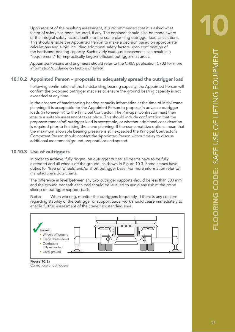
FLO
OR
ING
CO
DE
: SA
FE U
SE O
F LI
FTIN
G E
QU
IPM
ENT
51
10Upon receipt of the resulting assessment, it is recommended that it is asked what factor of safety has been included, if any. The engineer should also be made aware of the integral safety factors built into the crane planning outrigger load calculations. This should enable the Appointed Person to make a decision based on appropriate calculations and avoid including additional safety factors upon confirmation of the hardstand bearing capacity. Such overly cautious assessments can result in a “requirement” for impractically large/inefficient outrigger mat areas.
Appointed Persons and engineers should refer to the CIRIA publication C703 for more information/guidance on factors of safety.
10.10.2 Appointed Person – proposals to adequately spread the outrigger loadFollowing confirmation of the hardstanding bearing capacity, the Appointed Person will confirm the proposed outrigger mat size to ensure the ground bearing capacity is not exceeded at any time.
In the absence of hardstanding bearing capacity information at the time of initial crane planning, it is acceptable for the Appointed Person to propose in advance outrigger loads (in tonnes/m²) to the Principal Contractor. The Principal Contractor must then ensure a suitable assessment takes place. This should include confirmation that the proposed tonnes/m² outrigger load is acceptable, or whether additional consideration is required prior to finalising the crane planning. If the crane mat size options mean that the maximum allowable bearing pressure is still exceeded the Principal Contractor’s Competent Person should contact the Appointed Person without delay to discuss additional assessment/ground preparation/load spread.
10.10.3 Use of outriggersIn order to achieve ‘fully rigged, on outrigger duties’ all beams have to be fully extended and all wheels off the ground, as shown in Figure 10.3. Some cranes have duties for ‘free on wheels’ and/or short outrigger base. For more information refer to manufacturer’s duty charts.
The difference in level between any two outrigger supports should be less than 300 mm and the ground beneath each pad should be levelled to avoid any risk of the crane sliding off outrigger support pads.
Note: When working, monitor the outriggers frequently. If there is any concern regarding stability of the outrigger or support pads, work should cease immediately to enable further assessment of the crane hardstanding area.
Correct � Wheels off ground� Crane chassis level� Outriggers fully extended� Level ground
Figure 10.3aCorrect use of outriggers
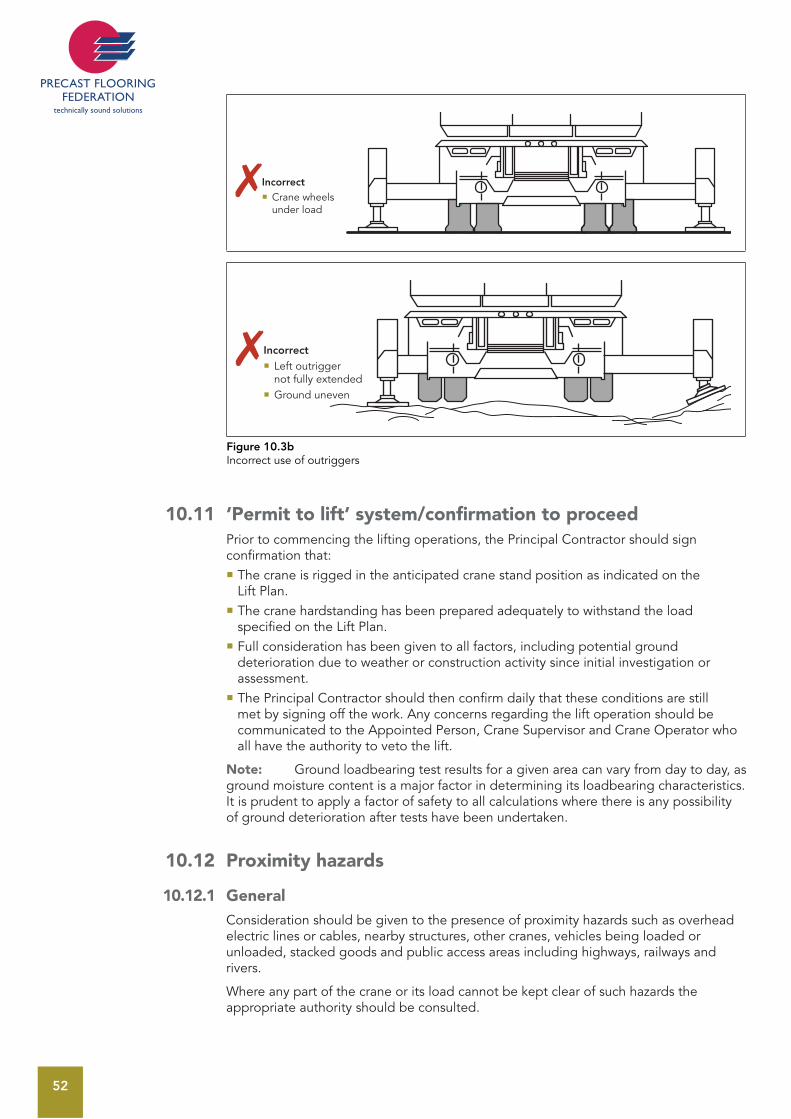
52
Incorrect � Crane wheels under load
Incorrect � Left outrigger not fully extended � Ground uneven
Figure 10.3bIncorrect use of outriggers
10.11 ‘Permit to lift’ system/confirmation to proceed Prior to commencing the lifting operations, the Principal Contractor should sign confirmation that:
The crane is rigged in the anticipated crane stand position as indicated on the Lift Plan. The crane hardstanding has been prepared adequately to withstand the load specified on the Lift Plan. Full consideration has been given to all factors, including potential ground deterioration due to weather or construction activity since initial investigation or assessment. The Principal Contractor should then confirm daily that these conditions are still met by signing off the work. Any concerns regarding the lift operation should be communicated to the Appointed Person, Crane Supervisor and Crane Operator who all have the authority to veto the lift.
Note: Ground loadbearing test results for a given area can vary from day to day, as ground moisture content is a major factor in determining its loadbearing characteristics. It is prudent to apply a factor of safety to all calculations where there is any possibility of ground deterioration after tests have been undertaken.
10.12 Proximity hazards
10.12.1 GeneralConsideration should be given to the presence of proximity hazards such as overhead electric lines or cables, nearby structures, other cranes, vehicles being loaded or unloaded, stacked goods and public access areas including highways, railways and rivers.
Where any part of the crane or its load cannot be kept clear of such hazards the appropriate authority should be consulted.
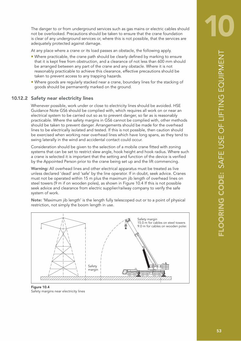
FLO
OR
ING
CO
DE
: SA
FE U
SE O
F LI
FTIN
G E
QU
IPM
ENT
53
10The danger to or from underground services such as gas mains or electric cables should not be overlooked. Precautions should be taken to ensure that the crane foundation is clear of any underground services or, where this is not possible, that the services are adequately protected against damage.
At any place where a crane or its load passes an obstacle, the following apply. Where practicable, the crane path should be clearly defined by marking to ensure that it is kept free from obstruction, and a clearance of not less than 600 mm should be arranged between any part of the crane and any obstacle. Where it is not reasonably practicable to achieve this clearance, effective precautions should be taken to prevent access to any trapping hazards. Where goods are regularly stacked near a crane, boundary lines for the stacking of goods should be permanently marked on the ground.
10.12.2 Safety near electricity lines Whenever possible, work under or close to electricity lines should be avoided. HSE Guidance Note GS6 should be complied with, which requires all work on or near an electrical system to be carried out so as to prevent danger, so far as is reasonably practicable. Where the safety margins in GS6 cannot be complied with, other methods should be taken to prevent danger. Arrangements should be made for the overhead lines to be electrically isolated and tested. If this is not possible, then caution should be exercised when working near overhead lines which have long spans, as they tend to swing laterally in the wind and accidental contact could occur.
Consideration should be given to the selection of a mobile crane fitted with zoning systems that can be set to restrict slew angle, hook height and hook radius. Where such a crane is selected it is important that the setting and function of the device is verified by the Appointed Person prior to the crane being set up and the lift commencing.
Warning: All overhead lines and other electrical apparatus must be treated as live unless declared ‘dead’ and ‘safe’ by the line operator. If in doubt, seek advice. Cranes must not be operated within 15 m plus the maximum jib length of overhead lines on steel towers (9 m if on wooden poles), as shown in Figure 10.4 If this is not possible seek advice and clearance from electric supplier/railway company to verify the safe system of work.
Note: ‘Maximum jib length’ is the length fully telescoped out or to a point of physical restriction, not simply the boom length in use.
Safetymargin
Safety margin15.0 m for cables on steel towers9.0 m for cables on wooden poles
Figure 10.4 Safety margins near electricity lines
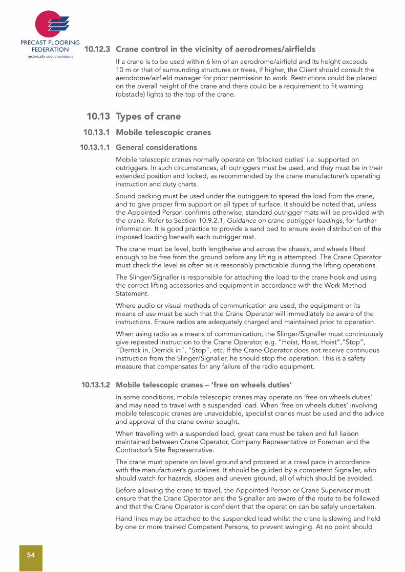
54
10.12.3 Crane control in the vicinity of aerodromes/airfieldsIf a crane is to be used within 6 km of an aerodrome/airfield and its height exceeds 10 m or that of surrounding structures or trees, if higher, the Client should consult the aerodrome/airfield manager for prior permission to work. Restrictions could be placed on the overall height of the crane and there could be a requirement to fit warning (obstacle) lights to the top of the crane.
10.13 Types of crane
10.13.1 Mobile telescopic cranes
10.13.1.1 General considerations
Mobile telescopic cranes normally operate on ‘blocked duties’ i.e. supported on outriggers. In such circumstances, all outriggers must be used, and they must be in their extended position and locked, as recommended by the crane manufacturer’s operating instruction and duty charts.
Sound packing must be used under the outriggers to spread the load from the crane, and to give proper firm support on all types of surface. It should be noted that, unless the Appointed Person confirms otherwise, standard outrigger mats will be provided with the crane. Refer to Section 10.9.2.1, Guidance on crane outrigger loadings, for further information. It is good practice to provide a sand bed to ensure even distribution of the imposed loading beneath each outrigger mat.
The crane must be level, both lengthwise and across the chassis, and wheels lifted enough to be free from the ground before any lifting is attempted. The Crane Operator must check the level as often as is reasonably practicable during the lifting operations.
The Slinger/Signaller is responsible for attaching the load to the crane hook and using the correct lifting accessories and equipment in accordance with the Work Method Statement.
Where audio or visual methods of communication are used, the equipment or its means of use must be such that the Crane Operator will immediately be aware of the instructions. Ensure radios are adequately charged and maintained prior to operation.
When using radio as a means of communication, the Slinger/Signaller must continuously give repeated instruction to the Crane Operator, e.g. “Hoist, Hoist, Hoist”,“Stop”, “Derrick in, Derrick in”, “Stop”, etc. If the Crane Operator does not receive continuous instruction from the Slinger/Signaller, he should stop the operation. This is a safety measure that compensates for any failure of the radio equipment.
10.13.1.2 Mobile telescopic cranes – ‘free on wheels duties’
In some conditions, mobile telescopic cranes may operate on ‘free on wheels duties’ and may need to travel with a suspended load. When ‘free on wheels duties’ involving mobile telescopic cranes are unavoidable, specialist cranes must be used and the advice and approval of the crane owner sought.
When travelling with a suspended load, great care must be taken and full liaison maintained between Crane Operator, Company Representative or Foreman and the Contractor’s Site Representative.
The crane must operate on level ground and proceed at a crawl pace in accordance with the manufacturer’s guidelines. It should be guided by a competent Signaller, who should watch for hazards, slopes and uneven ground, all of which should be avoided.
Before allowing the crane to travel, the Appointed Person or Crane Supervisor must ensure that the Crane Operator and the Signaller are aware of the route to be followed and that the Crane Operator is confident that the operation can be safely undertaken.
Hand lines may be attached to the suspended load whilst the crane is slewing and held by one or more trained Competent Persons, to prevent swinging. At no point should
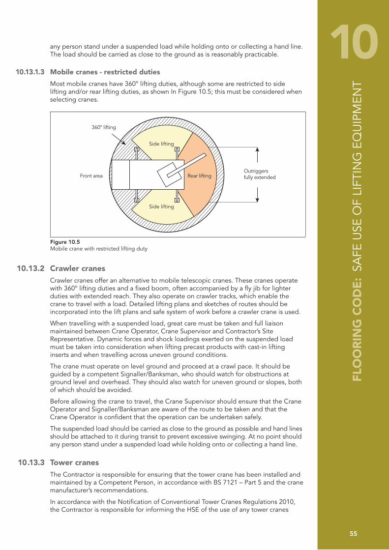
FLO
OR
ING
CO
DE
: SA
FE U
SE O
F LI
FTIN
G E
QU
IPM
ENT
55
10any person stand under a suspended load while holding onto or collecting a hand line. The load should be carried as close to the ground as is reasonably practicable.
10.13.1.3 Mobile cranes - restricted duties
Most mobile cranes have 360° lifting duties, although some are restricted to side lifting and/or rear lifting duties, as shown In Figure 10.5; this must be considered when selecting cranes.
Side lifting
Side lifting
Rear liftingFront areaOutriggersfully extended
360° lifting
Figure 10.5 Mobile crane with restricted lifting duty
10.13.2 Crawler cranesCrawler cranes offer an alternative to mobile telescopic cranes. These cranes operate with 360° lifting duties and a fixed boom, often accompanied by a fly jib for lighter duties with extended reach. They also operate on crawler tracks, which enable the crane to travel with a load. Detailed lifting plans and sketches of routes should be incorporated into the lift plans and safe system of work before a crawler crane is used.
When travelling with a suspended load, great care must be taken and full liaison maintained between Crane Operator, Crane Supervisor and Contractor’s Site Representative. Dynamic forces and shock loadings exerted on the suspended load must be taken into consideration when lifting precast products with cast-in lifting inserts and when travelling across uneven ground conditions.
The crane must operate on level ground and proceed at a crawl pace. It should be guided by a competent Signaller/Banksman, who should watch for obstructions at ground level and overhead. They should also watch for uneven ground or slopes, both of which should be avoided.
Before allowing the crane to travel, the Crane Supervisor should ensure that the Crane Operator and Signaller/Banksman are aware of the route to be taken and that the Crane Operator is confident that the operation can be undertaken safely.
The suspended load should be carried as close to the ground as possible and hand lines should be attached to it during transit to prevent excessive swinging. At no point should any person stand under a suspended load while holding onto or collecting a hand line.
10.13.3 Tower cranesThe Contractor is responsible for ensuring that the tower crane has been installed and maintained by a Competent Person, in accordance with BS 7121 – Part 5 and the crane manufacturer’s recommendations.
In accordance with the Notification of Conventional Tower Cranes Regulations 2010, the Contractor is responsible for informing the HSE of the use of any tower cranes

56
The Contractor is also responsible for ensuring that the lifting operation carried out by the tower crane is properly planned by a Competent Person in accordance with BS 7121 – Part 5. The person planning the lifting operation should have sufficient knowledge and experience of such operations. The plan must address risks identified during risk assessment and must show the resources required, in addition to procedures and responsibilities, so that the lifting operation can be carried out safely. The plan must also ensure that the lifting equipment remains safe for the different lifting operations/load configurations for which it will be used.
The Contractor is responsible for ensuring that the tower crane is capable of the duties required for lifting and installing the precast concrete units.
The Company is responsible for ensuring that the Contractor is provided with the weights and positions of the precast concrete units to allow the Contractor to fulfil his duties and adequately plan the lifting operation.
The Contractor must provide the Company with details of dedicated offloading points for delivery vehicles.
As with other cranes, tower cranes must be properly tested and certificated. They must be operated by trained Certificated persons, unless under the direct supervision of a Certificated person for the purpose of training. The only other persons who should be allowed access to a tower crane are those people authorised by the Crane Owner/hirer, in order that they can carry out their legitimate business, e.g. maintenance workers, inspectors. This should only be done only after work is suspended and the area is cordoned off.
The Contractor should give special consideration when two or more cranes are being operated in close proximity, to avoid jibs coming into contact with other crane equipment, e.g. lifting ropes.
10.14 Start of the lifting operation
10.4.1 General After carrying out the documentation check and having established that all is in order, the Appointed Person or Crane Supervisor can proceed as follows:
Obtain confirmation in writing from the Contractor’s Site Representative (or other Competent Person on their behalf) that the hardstanding has been adequately prepared to receive the outrigger loadings previously notified and indicated on the Lift Plan. Ensure that all personnel involved are familiar with the Safe Working Method Statement/Safe System of Work and are fully briefed on their roles and responsibilities. Discuss with all personnel involved the intended lifting operation and weight of loads being lifted, including information on the heaviest load and maximum radius of operation. Signed acknowledgement of this briefing must be obtained from each person involved. Before allowing the crane to enter the work area, the Crane Supervisor and the Crane Operator must ensure, by joint inspection, that the access, working and adjacent areas are safe and suitable. Particular attention should be paid to overhead obstructions, e.g. cables, trees, arches, scaffolding, etc. and underground hazards, e.g. trenches, cellars, basements, ramps and slopes, and these should be clearly identified in the Method Statement. Trenches or excavations that have recently been filled and not compacted sufficiently must be avoided. All proximity hazards must be identified and appropriate action taken as detailed in the Safe Working Method Statement. Supervise the manoeuvring of the crane onto and across site and into the required set up position as indicated on the lift plan, ensuring that the public and other site personnel are not being put at risk. Ensure that, before lifting, site personnel have been warned of the lifting operation and have vacated the working radius of the crane.
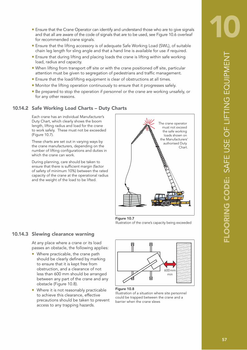
FLO
OR
ING
CO
DE
: SA
FE U
SE O
F LI
FTIN
G E
QU
IPM
ENT
57
10 Ensure that the Crane Operator can identify and understand those who are to give signals and that all are aware of the code of signals that are to be used, see Figure 10.6 overleaf for recommended crane signals. Ensure that the lifting accessory is of adequate Safe Working Load (SWL), of suitable chain leg length for sling angle and that a hand line is available for use if required. Ensure that during lifting and placing loads the crane is lifting within safe working load, radius and capacity. When lifting from transport off site or with the crane positioned off site, particular attention must be given to segregation of pedestrians and traffic management. Ensure that the load/lifting equipment is clear of obstructions at all times. Monitor the lifting operation continuously to ensure that it progresses safely. Be prepared to stop the operation if personnel or the crane are working unsafely, or for any other reasons.
10.14.2 Safe Working Load Charts – Duty Charts
Each crane has an individual Manufacturer’s Duty Chart, which clearly shows the boom length, lifting radius and load for the crane to work safely. These must not be exceeded (Figure 10.7).
These charts are set out in varying ways by the crane manufacturers, depending on the number of lifting configurations and duties in which the crane can work.
During planning, care should be taken to ensure that there is sufficient margin (factor of safety of minimum 10%) between the rated capacity of the crane at the operational radius and the weight of the load to be lifted.
The crane operator must not exceed the safe working loads shown on
the Manufacturers’authorised Duty
Chart.
Figure 10.7Illustration of the crane’s capacity being exceeded
10.14.3 Slewing clearance warning
At any place where a crane or its load passes an obstacle, the following applies:
Where practicable, the crane path should be clearly defined by marking to ensure that it is kept free from obstruction, and a clearance of not less than 600 mm should be arranged between any part of the crane and any obstacle (Figure 10.8).Where it is not reasonably practicable
to achieve this clearance, effective precautions should be taken to prevent access to any trapping hazards.
600 mmmin
Figure 10.8Illustration of a situation where site personnel could be trapped between the crane and a barrier when the crane slews
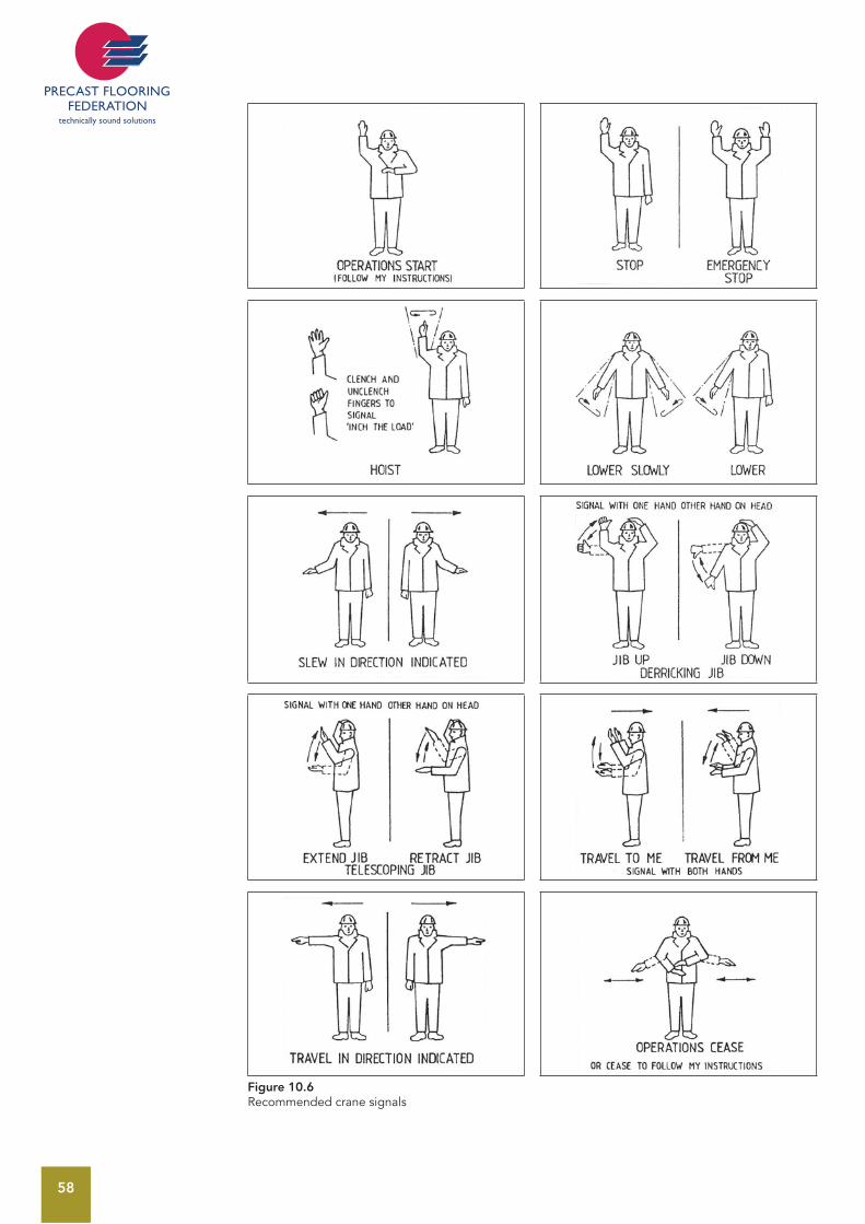
58
Figure 10.6 Recommended crane signals
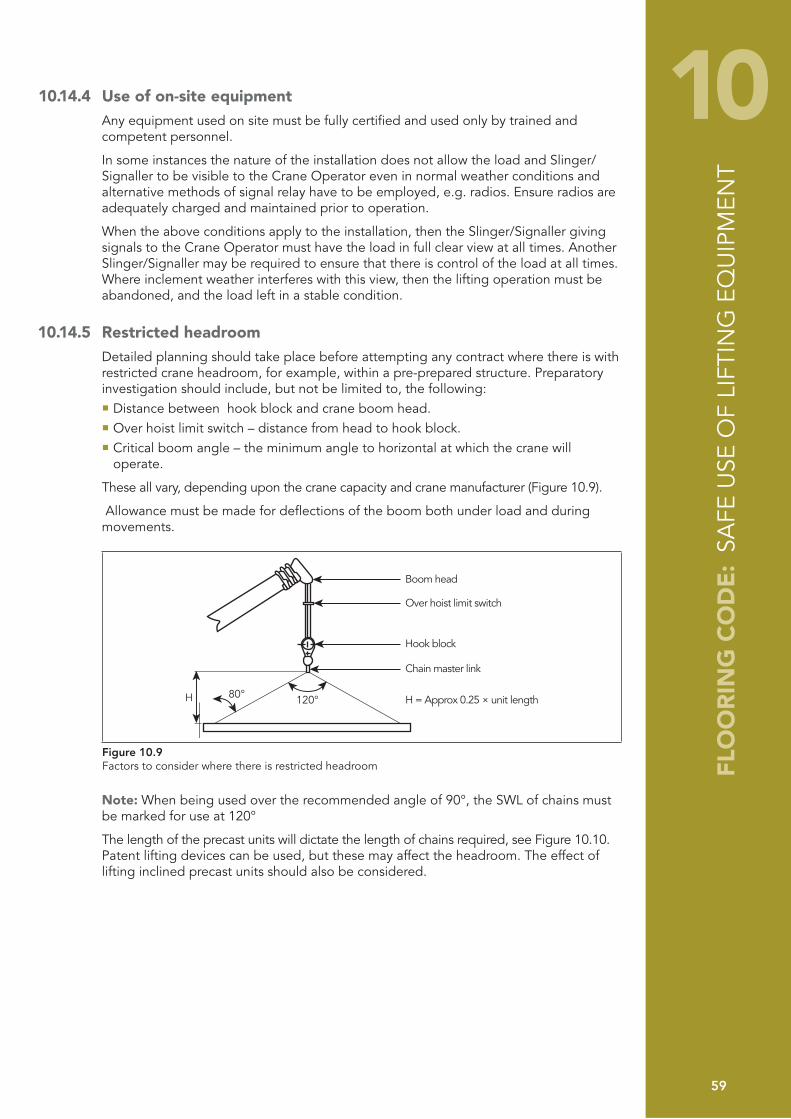
FLO
OR
ING
CO
DE
: SA
FE U
SE O
F LI
FTIN
G E
QU
IPM
ENT
59
10 10.14.4 Use of on-site equipmentAny equipment used on site must be fully certified and used only by trained and competent personnel.
In some instances the nature of the installation does not allow the load and Slinger/Signaller to be visible to the Crane Operator even in normal weather conditions and alternative methods of signal relay have to be employed, e.g. radios. Ensure radios are adequately charged and maintained prior to operation.
When the above conditions apply to the installation, then the Slinger/Signaller giving signals to the Crane Operator must have the load in full clear view at all times. Another Slinger/Signaller may be required to ensure that there is control of the load at all times. Where inclement weather interferes with this view, then the lifting operation must be abandoned, and the load left in a stable condition.
10.14.5 Restricted headroom Detailed planning should take place before attempting any contract where there is with restricted crane headroom, for example, within a pre-prepared structure. Preparatory investigation should include, but not be limited to, the following:
Distance between hook block and crane boom head. Over hoist limit switch – distance from head to hook block. Critical boom angle – the minimum angle to horizontal at which the crane will operate.
These all vary, depending upon the crane capacity and crane manufacturer (Figure 10.9).
Allowance must be made for deflections of the boom both under load and during movements.
120°
Boom head
Over hoist limit switch
Hook block
Chain master link
H = Approx 0.25 × unit length80°H
Figure 10.9Factors to consider where there is restricted headroom
Note: When being used over the recommended angle of 90°, the SWL of chains must be marked for use at 120°
The length of the precast units will dictate the length of chains required, see Figure 10.10. Patent lifting devices can be used, but these may affect the headroom. The effect of lifting inclined precast units should also be considered.
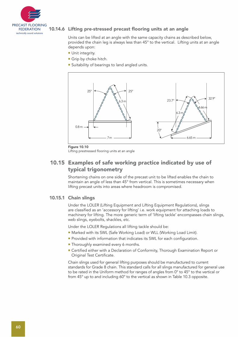
60
10.14.6 Lifting pre-stressed precast flooring units at an angle
Units can be lifted at an angle with the same capacity chains as described below, provided the chain leg is always less than 45° to the vertical. Lifting units at an angle depends upon:
Unit integrity.Grip by choke hitch.Suitability of bearings to land angled units.
6.3 m
6.3 m
4.66 m
25°
20°
23.7°32.9°
25°
0.8 m
7 m 6.65 m
Figure 10.10Lifting prestressed flooring units at an angle
10.15 Examples of safe working practice indicated by use of typical trigonometry Shortening chains on one side of the precast unit to be lifted enables the chain to maintain an angle of less than 45° from vertical. This is sometimes necessary when lifting precast units into areas where headroom is compromised.
10.15.1 Chain slingsUnder the LOLER (Lifting Equipment and Lifting Equipment Regulations), slings are classified as an ‘accessory for lifting’ i.e. work equipment for attaching loads to machinery for lifting. The more generic term of ‘lifting tackle’ encompasses chain slings, web slings, eyebolts, shackles, etc.
Under the LOLER Regulations all lifting tackle should be: Marked with its SWL (Safe Working Load) or WLL (Working Load Limit).Provided with information that indicates its SWL for each configuration.Thoroughly examined every 6 months. Certified either with a Declaration of Conformity, Thorough Examination Report or Original Test Certificate.
Chain slings used for general lifting purposes should be manufactured to current standards for Grade 8 chain. This standard calls for all slings manufactured for general use to be rated in the Uniform method for ranges of angles from 0° to 45° to the vertical or from 45° up to and including 60° to the vertical as shown in Table 10.3 opposite.
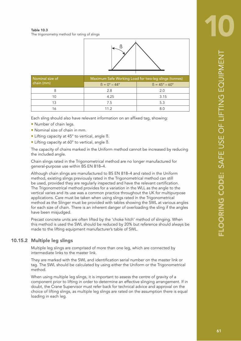
FLO
OR
ING
CO
DE
: SA
FE U
SE O
F LI
FTIN
G E
QU
IPM
ENT
61
10Table 10.3The trigonometry method for rating of slings
ß
Nominal size ofchain (mm)
Maximum Safe Working Load for two-leg slings (tonnes)
ß = 0° – 44° ß = 45° – 60°
8 2.8 2.0
10 4.25 3.15
13 7.5 5.3
16 11.2 8.0
Each sling should also have relevant information on an affixed tag, showing:Number of chain legs.Nominal size of chain in mm.Lifting capacity at 45° to vertical, angle ß.Lifting capacity at 60° to vertical, angle ß.
The capacity of chains marked in the Uniform method cannot be increased by reducing the included angle.
Chain slings rated in the Trigonometrical method are no longer manufactured for general-purpose use within BS EN 818–4.
Although chain slings are manufactured to BS EN 818–4 and rated in the Uniform method, existing slings previously rated in the Trigonometrical method can still be used, provided they are regularly inspected and have the relevant certification. The Trigonometrical method provides for a variation in the WLL as the angle to the vertical varies and its use was a common practice throughout the UK for multipurpose applications. Care must be taken when using slings rated in the Trigonometrical method as the Slinger must be provided with tables showing the SWL at various angles for each size of chain. There is an inherent danger of overloading the sling if the angles have been misjudged.
Precast concrete units are often lifted by the ‘choke hitch’ method of slinging. When this method is used the SWL should be reduced by 20% but reference should always be made to the lifting equipment manufacturer’s table of SWL.
10.15.2 Multiple leg slingsMultiple leg slings are comprised of more than one leg, which are connected by intermediate links to the master link.
They are marked with the SWL and identification serial number on the master link or tag. The SWL should be calculated by using either the Uniform or the Trigonometrical method.
When using multiple leg slings, it is important to assess the centre of gravity of a component prior to lifting in order to determine an effective slinging arrangement. If in doubt, the Crane Supervisor must refer back for technical advice and approval on the choice of lifting slings, as multiple leg slings are rated on the assumption there is equal loading in each leg.
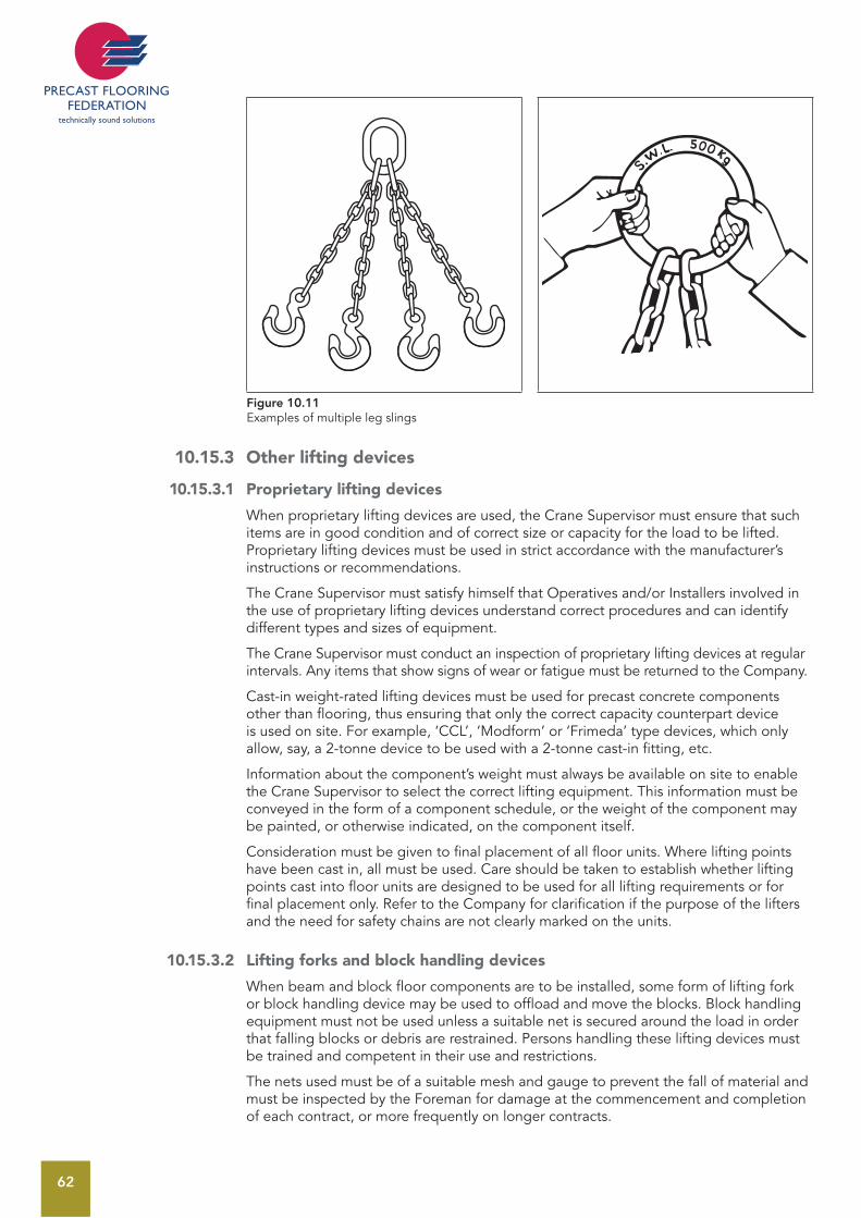
62
Figure 10.11 Examples of multiple leg slings
10.15.3 Other lifting devices
10.15.3.1 Proprietary lifting devices
When proprietary lifting devices are used, the Crane Supervisor must ensure that such items are in good condition and of correct size or capacity for the load to be lifted. Proprietary lifting devices must be used in strict accordance with the manufacturer’s instructions or recommendations.
The Crane Supervisor must satisfy himself that Operatives and/or Installers involved in the use of proprietary lifting devices understand correct procedures and can identify different types and sizes of equipment.
The Crane Supervisor must conduct an inspection of proprietary lifting devices at regular intervals. Any items that show signs of wear or fatigue must be returned to the Company.
Cast-in weight-rated lifting devices must be used for precast concrete components other than flooring, thus ensuring that only the correct capacity counterpart device is used on site. For example, ‘CCL’, ‘Modform’ or ‘Frimeda’ type devices, which only allow, say, a 2-tonne device to be used with a 2-tonne cast-in fitting, etc.
Information about the component’s weight must always be available on site to enable the Crane Supervisor to select the correct lifting equipment. This information must be conveyed in the form of a component schedule, or the weight of the component may be painted, or otherwise indicated, on the component itself.
Consideration must be given to final placement of all floor units. Where lifting points have been cast in, all must be used. Care should be taken to establish whether lifting points cast into floor units are designed to be used for all lifting requirements or for final placement only. Refer to the Company for clarification if the purpose of the lifters and the need for safety chains are not clearly marked on the units.
10.15.3.2 Lifting forks and block handling devices
When beam and block floor components are to be installed, some form of lifting fork or block handling device may be used to offload and move the blocks. Block handling equipment must not be used unless a suitable net is secured around the load in order that falling blocks or debris are restrained. Persons handling these lifting devices must be trained and competent in their use and restrictions.
The nets used must be of a suitable mesh and gauge to prevent the fall of material and must be inspected by the Foreman for damage at the commencement and completion of each contract, or more frequently on longer contracts.
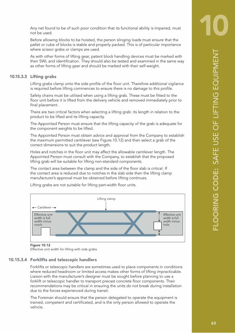
FLO
OR
ING
CO
DE
: SA
FE U
SE O
F LI
FTIN
G E
QU
IPM
ENT
63
10Any net found to be of such poor condition that its functional ability is impaired, must not be used.
Before allowing blocks to be hoisted, the person slinging loads must ensure that the pallet or cube of blocks is stable and properly packed. This is of particular importance where scissor grabs or clamps are used.
As with other forms of lifting gear, patent block handling devices must be marked with their SWL and identification. They should also be tested and examined in the same way as other forms of lifting gear and should be marked with their self-weight.
10.15.3.3 Lifting grabs
Lifting grabs clamp onto the side profile of the floor unit. Therefore additional vigilance is required before lifting commences to ensure there is no damage to this profile.
Safety chains must be utilised when using a lifting grab. These must be fitted to the floor unit before it is lifted from the delivery vehicle and removed immediately prior to final placement.
There are two critical factors when selecting a lifting grab: its length in relation to the product to be lifted and its lifting capacity.
The Appointed Person must ensure that the lifting capacity of the grab is adequate for the component weights to be lifted.
The Appointed Person must obtain advice and approval from the Company to establish the maximum permitted cantilever (see Figure.10.12) and then select a grab of the correct dimensions to suit the product length.
Holes and notches in the floor unit may affect the allowable cantilever length. The Appointed Person must consult with the Company, to establish that the proposed lifting grab will be suitable for lifting non-standard components.
The contact area between the clamp and the side of the floor slab is critical. If the contact area is reduced due to notches in the slab side then the lifting clamp manufacturer’s approval must be obtained before lifting continues.
Lifting grabs are not suitable for lifting part-width floor units.
Lifting clamp
Cantilever
Effective unitwidth is full width minus notch
Effective unitwidth is full width minus hole
Figure 10.12 Effective unit width for lifting with side grabs
10.15.3.4 Forklifts and telescopic handlers
Forklifts or telescopic handlers are sometimes used to place components in conditions where reduced headroom or limited access makes other forms of lifting impracticable. Liaison with the manufacturer’s designer must be sought before planning to use a forklift or telescopic handler to transport precast concrete floor components. Their recommendations may be critical in ensuring the units do not break during installation due to the forces experienced during transit.
The Foreman should ensure that the person delegated to operate the equipment is trained, competent and certificated, and is the only person allowed to operate the vehicle.

64
When a forklift or telescopic handler is to be used, the Appointed Person should ensure that adequate access and working areas are provided, in the same way as crane access and standing areas are agreed. Likewise, account should be taken of the terrain, height restrictions, noise, working environment, etc.
Should any attachment be used in conjunction with a forklift or telescopic handler, the selection and installation of the attachment should be carried out in consultation with the manufacturer or hirer of the equipment and the rated SWL altered accordingly. Additional training may be required for the operator where special attachments are to be used.
If it is necessary for the forklift or telescopic handler to travel with units, the route across site should be chosen with care, avoiding adverse gradients and obstructions. Wherever necessary the use of additional hard-core or similar measures should be implemented to minimise the unevenness of the site. Loads must be kept as low as possible to the ground to prevent the equipment becoming unstable.
At all times the operation of a forklift or telescopic handler should be carried out in full conformity with the instructions or recommendations of the hire company and/or the manufacturer, with particular attention being paid to the SWL and weight/height restrictions.
When handling precast components on the forks of a forklift truck or telescopic handler, it will be necessary to ensure that the forks of the vehicle are spaced such that the load is maintained in a stable condition and padded so that no damage is caused to the component being handled.

65
11 11 MOVEMENT OF UNITS BY OTHER MEANS
11.1 BarringComponents should be positioned as near as possible to their final position to minimise barring; however, the use of pinch or crowbars to move components is common to all types of floor unit and all categories of contract. The bar is used to move individual units into their final position, and to tighten up a floor after laying.
In whatever situation barring is carried out, there are basic precautions that must be observed:
Only competent Operatives should carry out barring operations. Only authorised personnel should be allowed within the working area and whilst barring is taking place, no person should be allowed within the exclusion zone(s), as set out in the Safe Working Method Statement. The ability of the structure to withstand this type of movement must be considered at the design stage and the Installers must satisfy themselves as to the robustness of the bearings before carrying out this operation and seek professional advice if unsure. If barring cannot be avoided and the bearings are not considered robust enough, the units must not be positioned until the bearing is improved, or some temporary measures taken, such as properly designed temporary support to the components or bracing of the bearings. Barring should be carried out by two Operatives, moving the unit simultaneously at each end of the unit. The bar itself must be of sound construction and of adequate strength, and should be long enough to enable the person barring the component to stand upright. The end of the bar should be shaped such that it can gain maximum purchase onto the unit to be moved, and the heel of the bar must be able to fully bear onto the units or structure being barred against. Where a possibility of damage to other surfaces exists, protective measures should be employed to prevent spalling or fracture. Components should not be moved by this method unless there are sufficient units or other elements of structure to provide a suitable platform on which the person(s) carrying out the operation can stand. Such a platform must be of sufficient size to enable the person(s) to properly brace himself and to ensure that, in the event of bar slippage, the person will not fall through a void, or over an edge. Section 13.4.1 of this Code of Practice deals with the question of edge protection. When moving components by this means, care must be taken to ensure that the units are not damaged to an extent that will impair their structural integrity. Components must be positioned or moved by a succession of small movements. No attempt should be made to slide or lift units for distances that would cause the operatives involved in the operation to lose their balance, or to hold excessive weight on a bar.
11.2 Jacking The use of jacks to raise precast units is not common and should be avoided wherever possible. In instances where there may be particular requirements to use jacking it should only be implemented after a full risk/design assessment has been undertaken. These jacking works should be short-term, for the purpose of removing chocks or chains and should not be used for temporary support. The points below should be considered:
Whenever jacks are used, they must be of adequate strength and capacity to safely raise and hold the load. Steel or hardwood wedges should be used to provide an
FLO
OR
ING
CO
DE
: M
OVE
MEN
T O
F U
NIT
S B
Y O
THER
MEA
NS
66
additional safeguard when a component is required to remain raised for some time; whenever practicable, adjustable steel props should be used. When jacking up a component, the Foreman must ensure that the jack is sited on a firm level base. If jacking from a floor, the Foreman must ensure by reference to the Company that the floor is capable of safely supporting the jack and the weight of any load being raised. The Precast Designer, in consultation with the Contractor, should determine whether back-propping of units is required and this should be set out in the Safe Working Method Statement. Care must be taken to ensure that the operation does not make the bearings unstable by introducing additional load or lateral forces to one end or leave the component in an unstable condition such that it could move whilst supported on the jack(s). Only authorised personnel should be allowed within the working area and, whilst jacking is taking place, no person should be allowed within the exclusion zone(s), as set out in the Safe Working Method Statement,. Jacks are often used in conjunction with adjustable steel props to raise components to a required level. In such circumstances, the Foreman must ensure that the adjustable prop is held vertically and will adequately carry the load. Components must be raised by only a few millimetres by this means; greater lifts or movement must be undertaken by lifting appliances. In all cases, jacks must be used in compliance with the instructions and recommendations of the manufacturer. The Foreman should conduct regular visual examinations of jacking equipment. Any defective items must not be used.
11.3 Other means of installing or moving componentsWhere, for practical reasons, cranes may not be employed, other methods may be devised and used, subject to a full design and installation risk assessment in agreement between the Contractor and the Company. Whenever possible such situations should be designed out.

67
12 12 ADDITIONAL ON-SITE WORKS
12.1 Temporary structural supportThe practice of installing precast units onto temporary bearings must be avoided wherever possible. In cases where such measures are unavoidable, the requirement to fix on temporary bearings must be notified to the Company at the design stage of the contract, and fixing must not progress until written confirmation has been obtained by the Contractor’s Site Representative from a competent technical authority that the temporary structure has been suitably designed.
12.2 ProppingShould propping be required as bearing enhancement during the construction phase, this will be indicated on the construction drawings and/or Safe Working Method Statement. Where required, mid-span propping, or back-propping, should also be indicated on the drawings/Safe Working Method Statement. All props should be designed and installed by Competent Persons employed by the Contractor.
12.3 In-situ concreteWet concrete, mould oil and timber treatments are skin irritants and the requirements of the COSHH Assessment and the Personal Protective Equipment at Work Regulations must be complied with.
In-situ concrete work must be executed in accordance with Working Drawings, Risk Assessments and Safe Working Method Statement.
No in-situ works should be carried out without reference to the Company so that any design implications can be assessed and the work recorded.
In-situ concrete can be supported either on permanent shutters, or on formwork. In the case of permanent shutters, these should be tight fitting to one another and their size should be such that the total area of concrete is supported. Permanent shutter units must be examined for cracking or other damage before any wet concrete is placed on them. These may need propping until the concrete is adequately cured. Where props are used, these must be designed by a Competent Person with due regard to number and position, and installed as directed by the Building Designer.
When temporary or permanent formwork is used, this must be of sufficient strength to support its own weight, and that of the concrete, together with reinforcement and the weight of any Operatives or plant engaged in the work. Formwork and steel reinforcement must be designed, constructed and installed by Competent Persons and should be closely examined before, during and after the placing of concrete, in accordance with the requirements of current Standards and Codes.
The Contractor must ensure that adequate scaffold for safe access to the work place is made available.
When using a mobile concrete mixing plant and equipment, care must be taken that these are operated in accordance with the manufacturer’s instructions.
Before commencing any in-situ concrete placement, the Foreman should ensure that the weather conditions are satisfactory so far as could be reasonably foreseen (as shown in Figure 12.1). Concreting should not commence in conditions likely to cause its failure or displacement, unless adequate measures are implemented to protect it. In all cases where work is not commenced, or doubt exists as to the suitability of weather conditions, the Company’s Representative must advise the Company of the situation.
FLO
OR
ING
CO
DE
: A
DD
ITIO
NA
L O
N-S
ITE
WO
RKS
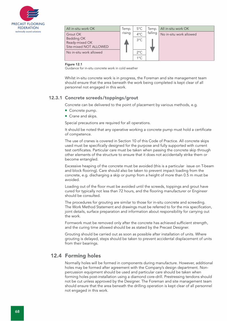
68
All in-situ work OK Temp. rising
5°C Temp. falling
All in-situ work OK
Grout OKBedding OKReady-mixed OKSite-mixed NOT ALLOWED
4°C No in-situ work allowed
3°C
No in-situ work allowed 2°C
1°C
Figure 12.1Guidance for in-situ concrete work in cold weather
Whilst in-situ concrete work is in progress, the Foreman and site management team should ensure that the area beneath the work being completed is kept clear of all personnel not engaged in this work.
12.3.1 Concrete screeds/toppings/groutConcrete can be delivered to the point of placement by various methods, e.g.
Concrete pump.Crane and skips.
Special precautions are required for all operations.
It should be noted that any operative working a concrete pump must hold a certificate of competence.
The use of cranes is covered in Section 10 of this Code of Practice. All concrete skips used must be specifically designed for the purpose and fully supported with current test certificates. Particular care must be taken when passing the concrete skip through other elements of the structure to ensure that it does not accidentally strike them or become entangled.
Excessive heaping of the concrete must be avoided (this is a particular issue on T-beam and block flooring). Care should also be taken to prevent impact loading from the concrete, e.g. discharging a skip or pump from a height of more than 0.5 m must be avoided.
Loading out of the floor must be avoided until the screeds, toppings and grout have cured for typically not less than 72 hours, and the flooring manufacturer or Engineer should be consulted.
The procedures for grouting are similar to those for in-situ concrete and screeding. The Work Method Statement and drawings must be referred to for the mix specification, joint details, surface preparation and information about responsibility for carrying out the work.
Formwork must be removed only after the concrete has achieved sufficient strength, and the curing time allowed should be as stated by the Precast Designer.
Grouting should be carried out as soon as possible after installation of units. Where grouting is delayed, steps should be taken to prevent accidental displacement of units from their bearings.
12.4 Forming holesNormally holes will be formed in components during manufacture. However, additional holes may be formed after agreement with the Company’s design department. Non-percussion equipment should be used and particular care should be taken when forming holes post-installation using a diamond core-drill. Prestressing tendons should not be cut unless approved by the Designer. The Foreman and site management team should ensure that the area beneath the drilling operation is kept clear of all personnel not engaged in this work.

FLO
OR
ING
CO
DE
: A
DD
ITIO
NA
L O
N-S
ITE
WO
RKS
69
12 12.5 Cutting units on siteWhere cutting is required on site, modifications to the unit may be made after agreement with the Company’s design department. Cuts should be made using the appropriate equipment in accordance with the Safe Working Method Statement and risk assessments. The Foreman and site management team should ensure that all cutting operations are carried out in a safe manner and the area is kept clear of all personnel not engaged in this work.
Any waste materials should be disposed of in accordance with the Site Waste Management Plan.

70
Page left blank intentionally
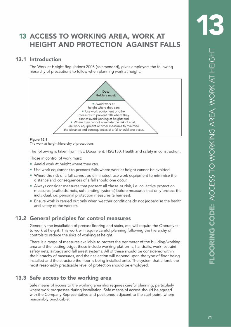
71
13 13 ACCESS TO WORKING AREA, WORK AT HEIGHT AND PROTECTION AGAINST FALLS
13.1 IntroductionThe Work at Height Regulations 2005 (as amended), gives employers the following hierarchy of precautions to follow when planning work at height:
DutyHolders must:
� Avoid work at height where they can;
� Use work equipment or othermeasures to prevent falls where theycannot avoid working at height; and
� Where they cannot eliminate the risk of a fall, use work equipment or other measures to minimise
the distance and consequences of a fall should one occur.
Figure 12.1The work at height hierarchy of precautions
The following is taken from HSE Document: HSG150: Health and safety in construction.
Those in control of work must:Avoid work at height where they can.Use work equipment to prevent falls where work at height cannot be avoided. Where the risk of a fall cannot be eliminated, use work equipment to minimise the distance and consequences of a fall should one occur. Always consider measures that protect all those at risk, i.e. collective protection measures (scaffolds, nets, soft landing systems) before measures that only protect the individual, i.e. personal protection measures (a harness). Ensure work is carried out only when weather conditions do not jeopardise the health and safety of the workers.
13.2 General principles for control measures Generally the installation of precast flooring and stairs, etc. will require the Operatives to work at height. This work will require careful planning following the hierarchy of controls to reduce the risks of working at height.
There is a range of measures available to protect the perimeter of the building/working area and the leading edge; these include working platforms, handrails, work restraint, safety nets, airbags and fall arrest systems. All of these should be considered within the hierarchy of measures, and their selection will depend upon the type of floor being installed and the structure the floor is being installed onto. The system that affords the most reasonably practicable level of protection should be employed.
13.3 Safe access to the working areaSafe means of access to the working area also requires careful planning, particularly where work progresses during installation. Safe means of access should be agreed with the Company Representative and positioned adjacent to the start point, where reasonably practicable.
FLO
OR
ING
CO
DE
: A
CC
ESS
TO W
ORK
ING
ARE
A, W
ORK
AT
HEI
GH
T
72
Typical methods include:Independent scaffolds.Suitably protected stairs and ramps.Fixed or mobile scaffold towers.Mobile access equipment.Secured ladders.
More detailed advice on the selection and use of access equipment is given in HSE guidance listed below:
CIS No 10 (rev. 4) Tower scaffolds. HSE Information Sheet MISC 614 Preventing falls from boom-type mobile elevating work platforms.HSG 150 Health and safety in construction (pages 14 to 37).
13.4 Working at height – control measuresThe hierarchy of precautions to be used has been outlined in Sections 13.1.
In practice, the perimeter of the building should be protected by the Contractor, by means of scaffold/guardrails/working platforms that prevent a fall.
The leading edge should be protected using the following hierarchy:
Active work restraint systems
This system prevents a fall. However, it limits access to the leading edge and relies on the operative to act and is therefore active and personal. In the precast flooring industry experience has shown that passive and collective systems are far more effective in preventing injury and are thus preferred (see Section 13.4.2.3 Work restraint systems).
Passive and collective systems
Systems that do not rely on the installer to operate them and are in place prior to the first unit being installed. Passive and collective systems include nets, airbags, decking and many other systems. They minimise the distance and consequence of a fall should one occur.
Active fall arrest systems
Systems for fall arrest rely on the Precast Installer to use them and are therefore active and personal. These systems require the calculation of the maximum drop an installer could suffer to ensure that the arrested drop is sufficiently short to prevent the fallen person coming into contact with the floor. Rescue of the fallen person must also be considered when designing such a system.
Note: All systems mentioned must comply with appropriate schedules given in the Work at Height Regulations.
13.4.1 Scaffold and edge protectionTo provide safe access to bearing level and access around the edge of the installation area, a scaffold with the required handrails must be in position prior to units being installed. The Contractor and the Company Representative should agree exactly what is necessary and what will be provided by the Contractor. The Contractor should ensure that all scaffolds are erected by a Competent Person, and are suitable and safe prior to work commencing. They must comply with the appropriate schedule in the Work at Height Regulations, i.e. the handrail should have a minimum height of 950 mm, the gap between rails is to be a maximum of 470 mm, and there is to be suitable protection against falling materials.
All scaffolds need to be constructed so as not to adversely affect the installation operation or the operation of the crane. The following recommendations are made for the different circumstances where scaffold edge protection systems could be used and must be installed to recognised standards such as The National Access & Scaffold Confederation (NASC) Guidance TG20:08
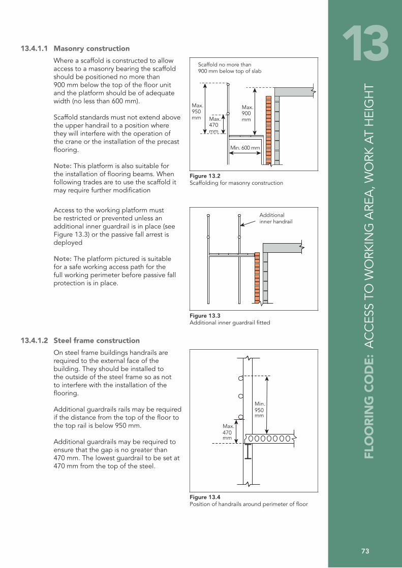
FLO
OR
ING
CO
DE
: A
CC
ESS
TO W
ORK
ING
ARE
A, W
ORK
AT
HEI
GH
T
73
13 13.4.1.1 Masonry construction
Where a scaffold is constructed to allow access to a masonry bearing the scaffold should be positioned no more than 900 mm below the top of the floor unit and the platform should be of adequate width (no less than 600 mm).
Scaffold standards must not extend above the upper handrail to a position where they will interfere with the operation of the crane or the installation of the precast flooring.
Note: This platform is also suitable for the installation of flooring beams. When following trades are to use the scaffold it may require further modification
Max.900mmMax.
470mm
Min. 600 mm
Scaffold no more than900 mm below top of slab
Max.950mm
Figure 13.2Scaffolding for masonry construction
Access to the working platform must be restricted or prevented unless an additional inner guardrail is in place (see Figure 13.3) or the passive fall arrest is deployed
Note: The platform pictured is suitable for a safe working access path for the full working perimeter before passive fall protection is in place.
Additionalinner handrail
Figure 13.3Additional inner guardrail fitted
13.4.1.2 Steel frame construction
On steel frame buildings handrails are required to the external face of the building. They should be installed to the outside of the steel frame so as not to interfere with the installation of the flooring.
Additional guardrails rails may be required if the distance from the top of the floor to the top rail is below 950 mm.
Additional guardrails may be required to ensure that the gap is no greater than 470 mm. The lowest guardrail to be set at 470 mm from the top of the steel.
Min.950mm
Max.470mm
Figure 13.4Position of handrails around perimeter of floor
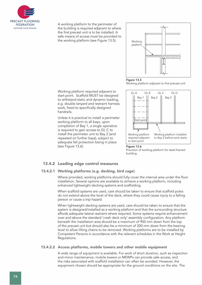
74
A working platform to the perimeter of the building is required adjacent to where the first precast unit is to be installed. A safe means of access must be provided to the working platform (see Figure 13.5). Working
platform
Figure 13.5Working platform adjacent to first precast unit
Working platform required adjacent to start point. Scaffold MUST be designed to withstand static and dynamic loading, e.g. double lanyard and restraint harness work, fixed to specifically designed handrails.
Unless it is practical to install a perimeter working platform to all bays, upon completion of Bay 1, a single operative is required to gain access to GL C to install the perimeter unit to Bay 2 (and repeated on further bays), subject to adequate fall protection being in place (see Figure 13.6).
Working platform required adjacent to start point
Working platform installed to Bay 2 before work starts
GL A GL B GL C GL D
Bay 1 Bay 2 Bay 3
Start point
Figure 13.6Provision of working platform for steel-framed building
13.4.2 Leading edge control measures
13.4.2.1 Working platforms (e.g. decking, bird cage)
Where provided, working platforms should fully cover the internal area under the floor installation. Several options are available to achieve a working platform, including enhanced lightweight decking systems and scaffolding.
When scaffold systems are used, care should be taken to ensure that scaffold poles do not extend above the level of the deck, where they could cause injury to a falling person or cause a trip hazard.
When lightweight decking systems are used, care should be taken to ensure that the system is designed/installed as a working platform and that the surrounding structure affords adequate lateral restraint where required. Some systems require enhancement over and above the standard ‘crash deck only’ assembly configuration. Any platform beneath the installation area should be a maximum of 900 mm down from the top of the precast unit but should also be a minimum of 200 mm down from the bearing level to allow lifting chains to be removed. Working platforms are to be installed by Competent Persons in accordance with the relevant schedules in the Work at Height Regulations.
13.4.2.2 Access platforms, mobile towers and other mobile equipment
A wide range of equipment is available. For work of short duration, such as inspection and minor maintenance, mobile towers or MEWPs can provide safe access, and the risks associated with scaffold installation can often be avoided. However, the equipment chosen should be appropriate for the ground conditions on the site. The
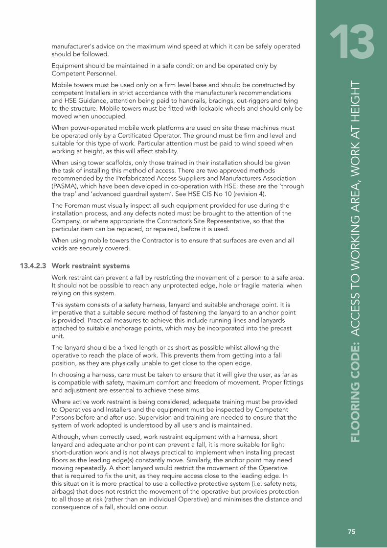
FLO
OR
ING
CO
DE
: A
CC
ESS
TO W
ORK
ING
ARE
A, W
ORK
AT
HEI
GH
T
75
13manufacturer's advice on the maximum wind speed at which it can be safely operated should be followed.
Equipment should be maintained in a safe condition and be operated only by Competent Personnel.
Mobile towers must be used only on a firm level base and should be constructed by competent Installers in strict accordance with the manufacturer’s recommendations and HSE Guidance, attention being paid to handrails, bracings, out-riggers and tying to the structure. Mobile towers must be fitted with lockable wheels and should only be moved when unoccupied.
When power-operated mobile work platforms are used on site these machines must be operated only by a Certificated Operator. The ground must be firm and level and suitable for this type of work. Particular attention must be paid to wind speed when working at height, as this will affect stability.
When using tower scaffolds, only those trained in their installation should be given the task of installing this method of access. There are two approved methods recommended by the Prefabricated Access Suppliers and Manufacturers Association (PASMA), which have been developed in co-operation with HSE: these are the ‘through the trap’ and ‘advanced guardrail system’. See HSE CIS No 10 (revision 4).
The Foreman must visually inspect all such equipment provided for use during the installation process, and any defects noted must be brought to the attention of the Company, or where appropriate the Contractor’s Site Representative, so that the particular item can be replaced, or repaired, before it is used.
When using mobile towers the Contractor is to ensure that surfaces are even and all voids are securely covered.
13.4.2.3 Work restraint systems
Work restraint can prevent a fall by restricting the movement of a person to a safe area. It should not be possible to reach any unprotected edge, hole or fragile material when relying on this system.
This system consists of a safety harness, lanyard and suitable anchorage point. It is imperative that a suitable secure method of fastening the lanyard to an anchor point is provided. Practical measures to achieve this include running lines and lanyards attached to suitable anchorage points, which may be incorporated into the precast unit.
The lanyard should be a fixed length or as short as possible whilst allowing the operative to reach the place of work. This prevents them from getting into a fall position, as they are physically unable to get close to the open edge.
In choosing a harness, care must be taken to ensure that it will give the user, as far as is compatible with safety, maximum comfort and freedom of movement. Proper fittings and adjustment are essential to achieve these aims.
Where active work restraint is being considered, adequate training must be provided to Operatives and Installers and the equipment must be inspected by Competent Persons before and after use. Supervision and training are needed to ensure that the system of work adopted is understood by all users and is maintained.
Although, when correctly used, work restraint equipment with a harness, short lanyard and adequate anchor point can prevent a fall, it is more suitable for light short-duration work and is not always practical to implement when installing precast floors as the leading edge(s) constantly move. Similarly, the anchor point may need moving repeatedly. A short lanyard would restrict the movement of the Operative that is required to fix the unit, as they require access close to the leading edge. In this situation it is more practical to use a collective protective system (i.e. safety nets, airbags) that does not restrict the movement of the operative but provides protection to all those at risk (rather than an individual Operative) and minimises the distance and consequence of a fall, should one occur.
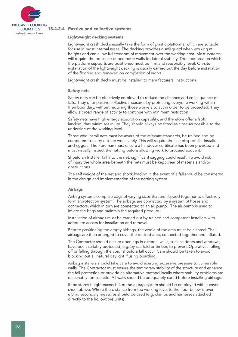
76
13.4.2.4 Passive and collective systems
Lightweight decking systems
Lightweight crash decks usually take the form of plastic platforms, which are suitable for use in most internal areas. The decking provides a safeguard when working at heights and can allow full freedom of movement over the working area. Most systems will require the presence of perimeter walls for lateral stability. The floor area on which the platform supports are positioned must be firm and reasonably level. On-site installation of the lightweight decking is usually carried out the day before installation of the flooring and removed on completion of works.
Lightweight crash decks must be installed to manufacturers’ instructions.
Safety nets
Safety nets can be effectively employed to reduce the distance and consequence of falls. They offer passive collective measures by protecting everyone working within their boundary, without requiring those workers to act in order to be protected. They allow a broad range of activity to continue with minimum restriction.
Safety nets have high energy absorption capability, and therefore offer a 'soft landing' that minimises injury. They should always be fitted as close as possible to the underside of the working level.
Those who install nets must be aware of the relevant standards, be trained and be competent to carry out the work safely. This will require the use of specialist Installers and riggers. The Foreman must ensure a handover certificate has been provided and must visually inspect the netting before allowing work to proceed above it.
Should an Installer fall into the net, significant sagging could result. To avoid risk of injury the whole area beneath the nets must be kept clear of materials and/or obstructions.
The self weight of the net and shock loading in the event of a fall should be considered in the design and implementation of the netting system.
Airbags
Airbag systems comprise bags of varying sizes that are clipped together to effectively form a protection system. The airbags are connected by a system of hoses and connectors, which in turn are connected to an air pump. The air pump is used to inflate the bags and maintain the required pressure.
Installation of airbags must be carried out by trained and competent Installers with adequate access for installation and removal.
Prior to positioning the empty airbags, the whole of the area must be cleared. The airbags are then arranged to cover the desired area, connected together and inflated.
The Contractor should ensure openings in external walls, such as doors and windows, have been suitably protected, e.g. by scaffold or timber, to prevent Operatives rolling off or falling through the void, should a fall occur. Care should be taken to avoid blocking out all natural daylight if using boarding.
Airbag installers should take care to avoid exerting excessive pressure to vulnerable walls. The Contractor must ensure the temporary stability of the structure and enhance the fall protection or provide an alternative method locally where stability problems are reasonably foreseeable. All walls should be adequately cured before installing airbags.
If the storey height exceeds 4 m the airbag system should be employed with a cover sheet above. Where the distance from the working level to the floor below is over 6.0 m, secondary measures should be used (e.g. clamps and harnesses attached directly to the hollowcore units)
FLO
OR
ING
CO
DE
: A
CC
ESS
TO W
ORK
ING
ARE
A, W
ORK
AT
HEI
GH
T
77
13There should be no overhead work in progress above the airbag installation area at any time while airbag modules are being set-up, moved/adjusted or de-rigged.
The absolute minimum airbag coverage should be 4.8 m ahead of the leading edge (direction of installation sequence), 2.4 m behind the leading edge and 2.4 m to each side (these to be increased to 4.8 m if the storey height exceeds 4 m).
This is the absolute minimum area permitted and should not be regarded as target coverage. Bagging installers should whole fill rooms, where practicable, to avoid the need for repeated access to the airbag area to move or adjust the modules. Flooring Operatives or Installers should ensure adequate time is allowed for airbag installers to provide adequate fall protection and fixing must not commence until this is in place.
The system must be continually monitored during its operation, i.e. to ensure airbags are fully inflated, and work suspended immediately in situations of non-compliance.
Other proprietary systems
Other systems not listed above may be utilized subject to risk assessment, taking into account fall distance onto the product, and its ability to mitigate the consequences of any fall (by reducing the severity of injury).
13.4.2.5 Fall arrest systems
Fall arrest systems do not prevent a fall, are not a collective protection measure and are therefore regarded as a personal protection measure and an active system. They are therefore lower down the hierarchy than the passive systems described at the start of Section 13.4.
These systems consist of a safety harness, lanyard and adequate anchorage point and aim to arrest a fall and minimise injury once a fall has occurred. Specialist advice and approval should be sought from the supplier of the equipment on the provision and location of suitable anchorage points.
A suitable system of rescuing the fallen person in less than 10 minutes must be present before work starts; serious injury or death can occur if the person remains suspended for prolonged periods following an arrested fall (Section 13.9).
Fall arrest systems can provide valuable protection, but they are not a substitute for effective fall prevention measures or collective protection measures. It must be clearly understood that, where practicable, proper working platforms, handrails, safety nets and airbags must be used in preference to fall arrest systems .
It is imperative that a suitable secure method of fastening the lanyard to an anchor point is provided, and that the lanyard length will prevent injury by arresting the fall before any part of the body hits the floor or any other part of the structure.
Practical measures to achieve this include running lines and lanyards attached to suitable anchorage points, which may be incorporated into the precast unit
Inertia reels may be used in fall arrest systems but assessments must be based on their design limitations and manufacturers’ recommendations.
In choosing a harness, care must be taken to ensure that it will give the user, as far as is compatible with safety, maximum comfort, freedom of movement and, in the event of a fall, every possible protection to the body from the shock of sudden arrest. Proper fittings and adjustment are essential to achieve these aims. The use of lanyards fitted with shock absorbers is recommended where the potential drop height permits the full lanyard deployment.
Where fall arrest devices are being considered, adequate training must be provided to Operatives and Installers and the equipment must be inspected by Competent Persons before and after use. Supervision and training are needed to ensure that the system of work adopted is understood by all users and the equipment is maintained.
78
13.4.2.6 Use of active and personal work restraint/fall arrest equipment
All persons who will use fall arrest/work restraint equipment must be fully trained in the understanding, inspection and use of that equipment and, in the case of fall arrest, the rescue procedures involved. The training must be provided by a suitably qualified instructor.
The user’s life may depend upon the good working order of the fall arrest/work restraint equipment provided and therefore the equipment must be subject to routine inspection, maintenance and, where required, replacement.
The following criteria must be taken into account before using work restraint systems:Adequate anchorage points.Means of adjustment of lanyard.Correct type of body harness.
The following criteria must be taken into account before using active fall arrest systems: Anchorage points and position require an adequate margin of strength and stability to withstand the dynamic and static forces.Type of lanyard.Free fall distance.Correct body harness.Time taken for rescue procedure.
In practice it is unlikely that active fall arrest systems will be capable of providing a safe system of work when installing precast concrete flooring products. Before it is used, a thorough risk assessment and method statement must be produced, taking into account all of the foregoing.
13.5 T-beam and block above ground floor levelsWhere practicable, a working platform will be required beneath the floor installation area when installing beam-and-block at upper floor levels. This is required to control the risk of falling between the beams and also the risks associated with manual handling of blocks.
13.6 Staircases Layout of flights and landings and the supporting structure differ on all stairwells. Each staircase should be assessed on its own merits and a risk assessment carried out to determine the most adequate and effective way of controlling the hazards.
13.6.1 Planning and co-ordinationWhen installing precast stairs and landings, it is often a requirement for associated trades to carry out works during the same day of installation, i.e. rigging and de-rigging of safety nets, installation and dismantling of scaffold or other passive fall arrest systems. Full consideration must be given to the planning and co-ordination of all trades, ensuring that all associated trades are fully aware of their requirements and sequence of attendance.
It is the Contractor’s duty, under the requirements of the CDM Regulations, to co-ordinate the requirements of scaffold protection to the stairwell during the construction phase. This will often necessitate a scaffolder being in attendance during the installation of a staircase.
13.6.2 HazardsThe main hazards associated with staircases/stairwells are:
Work at height whilst installing the flooring product around/close to the stairwell.
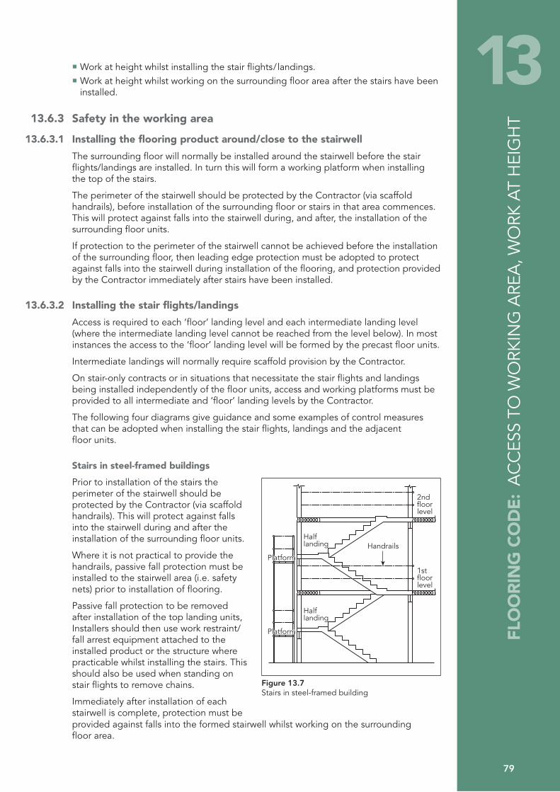
FLO
OR
ING
CO
DE
: A
CC
ESS
TO W
ORK
ING
ARE
A, W
ORK
AT
HEI
GH
T
79
13Work at height whilst installing the stair flights/landings. Work at height whilst working on the surrounding floor area after the stairs have been installed.
13.6.3 Safety in the working area
13.6.3.1 Installing the flooring product around/close to the stairwell
The surrounding floor will normally be installed around the stairwell before the stair flights/landings are installed. In turn this will form a working platform when installing the top of the stairs.
The perimeter of the stairwell should be protected by the Contractor (via scaffold handrails), before installation of the surrounding floor or stairs in that area commences. This will protect against falls into the stairwell during, and after, the installation of the surrounding floor units.
If protection to the perimeter of the stairwell cannot be achieved before the installation of the surrounding floor, then leading edge protection must be adopted to protect against falls into the stairwell during installation of the flooring, and protection provided by the Contractor immediately after stairs have been installed.
13.6.3.2 Installing the stair flights/landings
Access is required to each ‘floor’ landing level and each intermediate landing level (where the intermediate landing level cannot be reached from the level below). In most instances the access to the ‘floor’ landing level will be formed by the precast floor units.
Intermediate landings will normally require scaffold provision by the Contractor.
On stair-only contracts or in situations that necessitate the stair flights and landings being installed independently of the floor units, access and working platforms must be provided to all intermediate and ‘floor’ landing levels by the Contractor.
The following four diagrams give guidance and some examples of control measures that can be adopted when installing the stair flights, landings and the adjacent floor units.
Stairs in steel-framed buildings
Prior to installation of the stairs the perimeter of the stairwell should be protected by the Contractor (via scaffold handrails). This will protect against falls into the stairwell during and after the installation of the surrounding floor units.
Where it is not practical to provide the handrails, passive fall protection must be installed to the stairwell area (i.e. safety nets) prior to installation of flooring.
Passive fall protection to be removed after installation of the top landing units, Installers should then use work restraint/fall arrest equipment attached to the installed product or the structure where practicable whilst installing the stairs. This should also be used when standing on stair flights to remove chains.
Immediately after installation of each stairwell is complete, protection must be
PlatformPlatform
PlatformPlatform
Half landing
Half landing
2ndfloorlevel
Handrails
1stfloorlevel
Figure 13.7Stairs in steel-framed building
provided against falls into the formed stairwell whilst working on the surrounding floor area.

80
On steel frame structures access/platforms will be required to all bearing positions. Working platforms provide safe access to install intermediate landing and stair flight.
The surrounding floor will normally be installed around the stairwell before the stair flights / landings are installed. In turn this will form a working platform when installing at floor level.
Stairs in a masonry structure (first floor level)
The perimeter of the stairwell should be protected by the Contractor (by installing scaffold handrails), before installation of the surrounding floor or stairs.
This will protect against falls into the stairwell during and after the installation of the surrounding floor units. The protection may need to be adapted by the scaffolder in attendance to enable stair placement and reinstated immediately following stair installation.
Grouting operations cannot be undertaken without such protection.
1stfloorlevel
Figure 13.8Stairs in a masonry structure (first floor level)
The surrounding floor will normally be installed around the stairwell before the stair flights/landings are installed. In turn this will form a working platform when installing the top of the stairs.
After installation of the stairs is complete protection must be provided against falls into the formed stairwell whilst working on the surrounding floor area. In addition, the stairs must not be considered safe for access until handrails and edge protection have been provided by the Contractor.
Stairs in a masonry structure (2nd floor level and above). Example A, where stairwell can be protected
The perimeter of the stairwell should be protected by the Contractor (via scaffold handrails), before installation of the surrounding floor or stairs. This will protect against falls into the stairwell during and after the installation of the surrounding floor units.
The protection may need to be adapted by the scaffolder in attendance to enable stair placement and reinstated immediately following stair installation.
Grouting operations cannot be undertaken without such protection.
The surrounding floor will normally be installed around the stairwell before the stair flights/landings are installed. In turn this will form a working platform when installing the top of the stairs.
2ndfloorlevel
1stfloorlevel
Figure 13.9Stairs in a masonry structure (2nd floor level and above). Example A
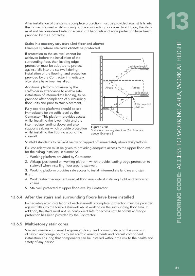
FLO
OR
ING
CO
DE
: A
CC
ESS
TO W
ORK
ING
ARE
A, W
ORK
AT
HEI
GH
T
81
13After installation of the stairs is complete protection must be provided against falls into the formed stairwell whilst working on the surrounding floor area. In addition, the stairs must not be considered safe for access until handrails and edge protection have been provided by the Contractor.
Stairs in a masonry structure (2nd floor and above) Example B, where stairwell cannot be protected
If protection to the stairwell cannot be achieved before the installation of the surrounding floor, then leading edge protection must be adopted to protect against falls into the stairwell during installation of the flooring, and protection provided by the Contractor immediately after stairs have been installed.
Additional platform provision by the scaffolder in attendance to enable safe installation of intermediate landing, to be provided after completion of surrounding floor units and prior to stair placement.
Fully boarded platforms should be set immediately below soffit level by the Contractor. This platform provides access whilst installing the lower flight and the intermediate landing above and also supports airbags which provide protection whilst installing the flooring around the stairwell.
AirbagAirbag
1st floor level
Fully boarded platform
2nd floor level
Figure 13.10Stairs in a masonry structure (2nd floor and above) Example B
Scaffold standards to be kept below or capped off immediately above this platform.
Full consideration must be given to providing adequate access to the upper floor level for the airbag installers. In summary: 1. Working platform provided by Contractor.2. Airbags positioned on working platform which provide leading edge protection to
stairwell when installing floor around stairwell.3. Working platform provides safe access to install intermediate landing and stair flight.4. Work restraint equipment used at floor levels whilst installing flight and removing
chains.5. Stairwell protected at upper floor level by Contractor.
13.6.4 After the stairs and surrounding floors have been installedImmediately after installation of each stairwell is complete, protection must be provided against falls into the formed stairwell whilst working on the surrounding floor area. In addition, the stairs must not be considered safe for access until handrails and edge protection has been provided by the Contractor.
13.6.5 Multi-storey stair coresSpecial consideration must be given at design and planning stage to the provision of cast-in anchorage points to aid scaffold arrangements and precast component installation ensuring that components can be installed without the risk to the health and safety of any person.
82
13.7 Falls from delivery vehiclesThe Contractor has a duty to ensure that all delivery vehicles are offloaded safely.
Where an Operative is required to access the trailer to unload the product there is a significant risk of injury from falls. Work at height on the trailer, and on the load, should therefore be avoided where reasonably practical.
Where work at height on the trailer and load cannot be avoided, then the Contractor should liaise with the Precast Installer and carry out an assessment of the site conditions. The hierarchy of control outlined in the Work at Height Regulations should be applied to reduce the risks of injury due to falls, as far as is reasonably practicable.
Control measures range from working platform gantries, handrail systems, airbag systems, safety net systems, personal work restraint systems and personal fall arrest systems. Such systems should be adopted where reasonably practicable. The most effective system to be used will largely depend upon the site conditions, the vehicle and the size, height and type of loads being delivered, the location of site and site condition.
All such safety systems will require careful planning. The Contractor should liaise with the Precast Installer and plan the offloading positions. The Contractor should also consider the Site Traffic Management Plan, other trades and deliveries, and ensure that adequate arrangements have been made to accommodate the system being used. Such planning must ensure that the offloading position is within reach of the specified crane, has adequate space for the installation and has adequate ground bearing capacity.
All systems must be examined/inspected by a Competent Person and used in accordance with the manufacturer’s recommendations and should be visually inspected before use.
Wherever possible, work at height on the trailer should be avoided. Where it cannot be avoided, safe access to and from the trailer is essential, and suitable in-built steps or secured ladders/handholds should be used.
13.8 Use of laddersLadders should be used only as access or for light work of short duration, lasting no more than 15 to 30 minutes where other safer means, such as scaffold towers or Mobile Elevating Work Platforms (MEWPs) have been considered and found not to be reasonably practicable.
Properly constructed and secured ladders, combined with the use of safety harnesses, static lines or anchorage points, may also be practicable in certain conditions where the working height precludes the use of mobile towers.
When ladders are used, they need to be of the correct type, i.e. a suitable grade of industrial ladder. They should be in good condition and effectively secured to prevent movement (Figure. 13.11). Permanent means of securing ladders at identified access points can improve ladder safety. This avoids the need for footing when ladders are tied and untied. Those who use, inspect and secure ladders should be competent to do so.
Ladders may provide safe access, but their use is not always appropriate. Factors to be considered include:
The length of the ladder required. Very long ladders are heavy to handle and may need staying to reduce flexing in use.Correct angle of ladder – for every four up go one out (Figure 13.12). There must be an extension of at least 1 m above landing point to provide a secure handhold. Ensure the ladder is adequately secured at foot and landing point. The need to carry tools, equipment, materials, small components, etc. Both hands should be free when climbing a ladder.

83
13
FLO
OR
ING
CO
DE
: A
CC
ESS
TO W
ORK
ING
ARE
A, W
ORK
AT
HEI
GH
T
The Operative must have a secure handhold and at least three points of contact when using the ladder. The Operative must not overreach. The requirement for records of formal periodic inspections by the Contractor in accordance with the manufacturer’s recommendations.
The Foreman must visually inspect all ladders provided for use during the installation process, and any defects noted must be brought to the attention of the Company, or where appropriate, the Contractor’s Site Representative, so that the particular item can be replaced or repaired before it is used.
For every four up, go one out
4
1
Figure 13.11Secure ladder fixing
Figure 13.12Correct ladder angle
13.9 Rescue proceduresA rescue procedure must be in place on all occasions where passive fall arrest or active fall arrest are utilised and where, therefore, a fall is still possible, e.g. fall into airbag, safety net, use of fall arrest safety harness. Any potential rescue procedure must be evaluated at the planning stage of the job and recorded accordingly. When planning for rescue, consideration should be given to the type of situation from which the casualty may need to be recovered, and the type of fall protection equipment that the casualty would be using. It is essential that individuals undertaking work at height are competent in appropriate rescue techniques and emergency procedures. These should form part of their initial and ongoing training. In addition to this, rescue techniques should be practiced at regular intervals, and at the start of any work situation that is unfamiliar to any of the work team.
It must be stressed that reliance upon the Emergency Services to assist with a rescue should not be part of the rescue plan. This is because there is a possible lack of appropriate equipment for the rescue, as well as the likelihood of an extended time period between the onset of the fall and the arrival of the Emergency Services.
It is also important to consider what equipment is going to be suitable for a rescue and whether it will be available on site. Equipment that could be utilised could include:
A MEWP.A proprietary rescue system.A system provided by the Contractor.A crane with a person riding cage.
84
Note: Manufacturers provide various types of suspension trauma relief equipment for use by a suspended person. These can delay the effects of suspension trauma, but they only work on conscious and able casualties; they are not an alternative to rescue.
All rescue planning and operations should address the following issues:The safety of the persons carrying out or assisting with the rescue.The anchor points to be used for the rescue equipment. The suitability of equipment (anchors, harnesses, attachments and connectors) that has already arrested the fall of the casualty for use during the rescue. The method that will be used to attach the casualty to the rescue system. The direction that the casualty needs to be moved to get them to the point of safety, (raising, lowering or lateral).The first aid needs the casualty may have with respect to injury or suspension trauma.The possible needs of the casualty following the rescue.
13.9.1 Suspension intoleranceSuspension Intolerance is a condition in which a person suspended in a harness can experience pallor, cold sweats, nausea, ringing in the ears, blurred vision, dizziness, feeling faint, loss of consciousness and eventually death.
All users of personal fall protection systems, and others involved with work at a height, should be aware of the following precautions that might need to be taken in the event of a casualty being held in a suspended position.
The longer the casualty is suspended without moving, the greater the chances are of suspension intolerance developing and the more serious it is likely to be. Therefore, if an injured person is suspended in a harness, the aim should be to carry out the rescue within 10 minutes. This is particularly important for a casualty who is motionless. Unless the suspended person can be immediately retrieved, call 999 for assistance. A conscious casualty should be encouraged to mobilise their four limbs, to stimulate circulation of the blood. Frequent ‘pumping,’ of the legs against a firm surface will also activate the muscles and improve blood circulation. After rescue, providing there are no injuries, there was no medical reason for the fall and the casualty is conscious, they should be checked by a competent first aider who may advise them to avoid standing and to sit down until satisfied they have fully recovered (maximum 30 minutes). After rescue, if the casualty is unconscious or semi-conscious, they must be attended to by a competent first aider who must have also contacted the emergency services. They must ensure that the patient’s airway is open, the patient is breathing and only then place the patient in the traditional recovery position until the emergency services are in attendance. The ambulance service should be advised that the patient needs to be treated for orthostatic shock or intolerance.
Important!
Only move the casualty to a fully horizontal position on the advice of qualified medical personnel. Laying the casualty down horizontally could be life threatening, as the blood that has accumulated in the legs flows abruptly into the heart creating a risk of heart failure due to overstrain.

85
14 14 PROTECTION OF THIRD PARTIES
14.1 Other trades or persons on siteThe Work Area associated with the flooring installation must be designated a ‘prohibited area’ to all persons, other than those engaged in the installation of the floor. The Contractor must actively enforce this prohibition, and the Foreman must co-operate with the Contractor to ensure that fencing, gates and barriers remain secure and that notices are not removed or obscured.
The Contractor and Foreman must ensure that components are not hoisted over areas where other persons are working. This may include several levels in multi-storey work.
Operatives and Installers engaged in the installation of the flooring must at all times execute their work with a due regard for the health and safety of other workers or persons. They must observe and comply with the Safe Working Method Statement in force on any particular contract insofar as such rules or requirements affect their operations, and they must also comply with any rules or requirements imposed by the Contractor.
The Foreman must ensure that the work area is kept clean and tidy so far as this is reasonably practicable and at the end of the working day the area should be left free of debris. Materials must be safely stacked.
14.2 Members of the publicThe lifting of components and materials may present a hazard to the public, especially where the delivery vehicle is unloaded from the public highway.
When unloading from the public highway, the Contractor must obtain the necessary statutory permissions and the area used for off loading must be designated a ‘prohibited area’ to all persons other than those engaged in the installation of the floor.
The Contractor must provide all necessary cones, warning barriers, notices, traffic signs and lighting to allow the safe passage of pedestrians and roads traffic. If deemed necessary, the prohibited area may have to be policed.
On sites where the building operations are in close proximity to public places or highways, additional care must be taken to prevent materials or debris falling from the works. Where the Contractor has provided measures to prevent such falls, or to protect the public, the Operatives and Installers engaged in the installation of the flooring must not remove or interfere with these measures in any way.
Any debris or material that falls from delivery vehicles must be removed from the public highway or public area and the area left clean and hazard free.
When the installation involves the operation of a crane in a third party’s air space, the Contractor must obtain the necessary permissions and ensure that the appropriate steps are taken to protect third parties and the public in these areas. Where practicable, loads should not be hoisted over occupied buildings. Due consideration should be given when lifting close to any adjacent occupied building.
During the course of the lifting operation the Contractor must ensure that members of the public are not in the vicinity of the suspended load or lifting equipment.
The Foreman must liaise and co-operate in all respects with the Contractor’s Site Representative to ensure compliance with any measures, provisions or rules previously agreed with the Contractor or with any statutory provisions for the protection of the public.
In the event that any of the foregoing requirements are not met, lifting should cease immediately.
FLO
OR
ING
CO
DE
: PR
OTE
CTI
ON
OF
THIR
D P
ART
IES

86
Page left blank intentionally

87
15 15 SUPPLIER AND SUB-CONTRACTOR COMPETENCY ASSESSMENT
15.1 IntroductionEmploying companies must assess suppliers and Installers and satisfy themselves that they are competent to carry out the proposed work safely, in accordance with the CDM Regulations 2007 and its approved Code of Practice. This is to include suppliers and Installers of safety equipment and installation companies.
15.2 Assessment criteriaGuidance on how to assess individuals and organisations is given in the CDM Regulations 2007 approved Code of Practice in the section entitled Competence and training and also in Appendix B of this Code of Practice.
FLO
OR
ING
CO
DE:
SU
PPLI
ER A
ND
SU
B-C
ON
TRA
CTO
R C
OM
PETE
NC
Y A
SSES
SMEN
T

88
Page left blank intentionally
89
A APPENDIX A: Precast Flooring Federation standard health, safety and welfare attendances Required on sub-contracts for the supply and fixing of precast concrete flooring and components.
This document forms part of and should be read in conjunction with the PFF Code of Practice for safe installation of precast concrete flooring, available from the Precast Flooring Federation, 60 Charles Street, Leicester LE1 1FB or www.precastfloors.info
The Attendances contained herein shall be provided on site by the Contractor for the Precast Flooring Sub-contractor’s use, free of charge, and shall comply with the requirements of the Health and Safety at Work Act and supporting Regulations (Where no Contractor exists all references to the Contractor shall mean the Precast Flooring Sub-contractor’s client).
1 Crane and vehicle access and hardstanding 1.1 The Contractor shall provide and maintain hard roads, hardstanding and stacking
areas, entirely suitable for the operations and for safe passage and working of personnel and plant; this will include levelling if necessary. Maintenance of the same should take into account deterioration due to adverse weather, continued use, etc. The hardstanding for the crane must be maintained as indicated on the lifting plan, for the duration of the contract.
1.2 For the guidance of the Contractor, the Precast Flooring Sub-contractor shall provide information regarding the delivery vehicles and cranes on which his quotations are based.
1.3 Parking and/or offloading facilities for Installers/Operatives must be provided by the Contractor.
1.4 Where practicable, fall protection systems will be used around delivery vehicles. Planning is required by the Contractor to ensure that adequate space is made available to accommodate the system and to minimise disruption.
1.5 The Contractor shall provide and maintain any access on to site from the public highway, entirely suitable for the safe passage of lorries and cranes. Should road signs, bollards, etc, or police permission be required in connection with such access, then the provision of, or application for them shall be the responsibility of the Contractor.
1.6 Where erection operations are to be carried out from the public highway, all road signs, traffic and pedestrians control, all necessary permissions, etc, shall be the responsibility of the Contractor.
1.7 Where craneage or any other type of lifting appliance is to be provided by the Contractor, he must provide an Appointed Person (BS 7121) to plan the lift unless agreed otherwise. Craneage must be adequate for the purpose and the Precast Flooring Subcontractor shall be afforded its unrestricted use whenever required, including the use of a trained operator and signaller where applicable.
1.8 Where craneage is working the Contractor must prevent access by any other persons to the crane’s operating area.
FLO
OR
ING
CO
DE
: A
PPEN
DIX
A: A
TTEN
DA
NC
ES
90
2 Structural obstructions 2.1 The Contractor shall be responsible for the re-routing, removal and/or making safe
of any obstructions (including parts of the structure such as purlins, cross-bracing and scaffold standards) which will foul or hinder a crane boom or suspended load. This must be carried out before the arrival on site of the Precast Flooring Subcontractor. The Contractor shall also be responsible for any subsequent replacement of such items.
3 Proximity hazards 3.1 The Contractor must inform the Precast Flooring Subcontractor at tender stage of
any proximity hazards. Such hazards may include overhead electric cables, electricity substations, railway lines, airfields, waterways, environmentally protected areas, restrictions to third party air-space, basements, underground services, etc. The Contractor shall be responsible for obtaining any necessary approvals/permission from relevant authorities/owners.
4 Safe access and protection against falls 4.1 Safe access to all working levels shall be provided by the Contractor.
Scaffolding to the perimeter of working areas, together with handrails, guardrails, platforms or staging required for access and/or to prevent Operatives falling, shall be provided and installed by the Contractor. Perimeter working platforms shall be no more than 900 mm below the top of the precast floor.
4.2 When working at heights, where there is a risk of significant injury due to falling (e.g. from upper floors and/or floors over basements), the hierarchy of fall protection must be followed. Therefore passive fall protection must be provided wherever reasonably practicable before installation of all precast concrete floors. The Precast Flooring Subcontractor may at his discretion offer this service.
4.3 Protection can be achieved by using working platforms, staging, lightweight decking systems, safety nets or airbags and the chosen measure should protect the whole of the upper-level work area.
4.4 The Contractor shall be responsible for ensuring that all voids and external openings, such as doors and windows, have been suitably protected to prevent Operatives or equipment from falling through or rolling off .
5 Welfare 5.1 All welfare facilities shall be afforded to the Precast Flooring Supplier/Installer by way of
an Attendance by the Contractor.
6 Structural stability 6.1 Prior to the Precast Flooring Supplier/Installer commencing work on site, adequate
hard, level bearings designed to take account of the construction loadings/processes shall be provided by the Contractor. In addition, the Contractor shall be responsible for ensuring that:
All brickwork, blockwork or concrete is cured, stable and fit to receive precast concrete units, and that steelwork is secure and stable. Isolated piers or toothed walls are made stable and adequate by the application of temporary measures as necessary. Lintels, steel angles and RSJs etc. are bedded as necessary, securely fixed to the
FLO
OR
ING
CO
DE
: A
PPEN
DIX
A: A
TTEN
DA
NC
ES
91
Awall and have adequate safe bearing at each end to avoid collapse, displacement or similar movement. Propping maybe necessary to achieve this required stability, in accordance with the lintel manufacturer’s/building designer’s recommendations. All walls and partitions not providing bearing to units should be left one course down from the soffit level to allow the units to be safely positioned.If weep holes are provided, they are kept clear. The practice of installing precast units onto temporary bearings should be avoided wherever possible. In cases where such measures are unavoidable, fixing must not commence until written confirmation has been obtained by the Contractor from a competent technical authority that the temporary structure has been suitably designed, taking into account the more onerous forces during the construction phase. Permission must also be obtained from the Precast Flooring Subcontractor’s Technical Department.
7 General 7.1 If the Contractor shall fail to make available any of the facilities above stipulated to be
provided by him, the Precast Flooring Subcontractor may at his sole option suspend work on the contract until the required facility has been made available.
7.2 Any delay in the performance of the works arising from such suspension shall not be deemed a failure on the Precast Flooring Subcontractor’s part to proceed with the works in accordance with provisions of his subcontract, and he shall be entitled to claim against the Contractor in respect of any loss, damage or expense he may have suffered by reason of the Contractor’s default or the delay caused thereby.

92
Page left blank intentionally
93
B APPENDIX B: Precast Flooring Federation Construction (Design and Management) Regulations 2007
Installing precast concrete floors is a high risk activity that usually involves the use of cranes and Operatives working at heights.
The purpose of the following information is to highlight some of the points covered in this Code of Practice, to assist Engineers, Designers, Contractors and CDM Coordinators in meeting the requirements of the CDM Regulations. More detailed information is provided in the Code of Practice, in particular Section 4 – Design Stage Considerations. In the text which follows the Precast Designer is not the Building Designer.
1 The existing environment 1.1 The sizes and weights of the components will determine the method of off-loading and
placing the units. The precast units are usually delivered to site on articulated lorries; narrow roads or restricted access may necessitate the use of rigid lorries.
1.2 Pedestrian and traffic management measures should be considered, especially if the delivery lorries are off-loaded from the public highway.
1.3 Excavations, underground services, drains and basements are a hazard and strengthening may be required to safely support the loads imposed by the crane’s outriggers. Adequate access to these areas must be provided and maintained.
1.4 The presence of power lines, railway tracks, trees or overhead structural obstructions may hinder the operation of cranes. On restricted sites it may be necessary for loads to be lifted over adjacent land and buildings. In these circumstances, permission should be obtained to operate within the airspace of third parties.
2 Design and planning 2.1 The Regulations require that a designer’s competence has to be considered in the
light of health and safety. Members of the Precast Flooring Federation should be able to demonstrate their experience and competence in the design and manufacture of precast flooring.
2.2 To assist the Precast Designer, the following information should be provided at Tender Stage:
Pre-construction information / Construction Phase Health and Safety Plan.Design loads including finishes and imposed loads. Drawings showing the supporting structure for the precast units and direction of span.Phasing or sequencing of the works.Site and services plan.
2.3 Building Designers must take into account stability of the structure during the installation of precast units:
The design should allow for the removal, prior to the installation of the units, of overhead obstructions such as purlins or bracing, that are likely to foul or hinder the crane boom or suspended load. Precast units can be heavy. Bearings must be adequate and be robust enough to withstand normal unit fixing operations including landing and barring.
FLO
OR
ING
CO
DE
: A
PPEN
DIX
B: C
DM
REG
ULA
TIO
NS
94
Lintels or steel beams must be securely fixed and have adequate safe bearing at each end to avoid overturning, excessive deflection, or collapse when the precast units are placed. Consideration must be given to the unequal loading of unrestrained walls, steel beams or lintels when precast units are being placed. Similarly, consideration must be given to the fixing of passive fall arrest systems e.g. safety nets, airbags, etc. The practice of installing precast units onto temporary bearings should be avoided wherever possible. In cases where such measures are unavoidable, the temporary structure must be designed and installed by a Competent Person provided by the Contractor.
2.4 When an order is placed for the precast concrete units, the Contractor should provide the Precast Flooring Sub-Contractor with the following information:
Any relevant amendments to the Health and Safety Plan. Fully dimensioned ‘Construction Issue’ drawings, detailing the supporting structure for the floors and any other aspects which may affect the floor design. Loadings, including type and location of partitions, types of finish, etc. Positions and sizes of all holes, notches or rebates required in the flooring. Provisional sequencing and programme dates. Where working in the vicinity of rail tracks, underground railway lines, or energy supply structures such as power cables, all permissions that are required from owners or controllers are to be given in advance, along with any instructions for the safe working of the installer.
3 Construction phase 3.1 The installation of precast concrete units should only be undertaken by specialists.
Members of the Precast Flooring Federation employ Installers who are trained, competent and experienced in this work.
3.2 The Contractor must ensure that the Precast Flooring Federation Standard Health, Safety and Welfare Attendances have been provided.
3.3 Installing precast floors is a high-risk operation and should not be undertaken without the provision of a job-specific method statement and risk assessments, which may address some or all of the following activities:
Manual handlingWorking at heights with risk of personnel/objects fallingWorking with cranesHandling or cutting concrete products, working with wet concrete or mortar
3.4 The Principal Contractor must ensure that other trades and the public are kept out of the working area covered by cranes used for installing the precast units.
3.5 A major consideration for the Building Designer and Contractor should be the stability of the structure during the installation of the precast concrete units:
Sufficient time must be allowed for masonry mortar to mature sufficiently to achieve adequate strength and stiffness. The designer should give consideration to the provision of adequate wall thickness, particularly where shared bearings occur on lightweight masonry blocks. Consideration should be given to the proposed sequence of construction and the effects of any temporary removal of parts of the structure to facilitate the safe installation of the precast units. Sufficient time must be allowed for a grouted floor to mature prior to loading out with materials, which should not exceed the load for which the floor has been designed. Advice should be sought prior to the storage of unfixed materials on the floors by following trades.

FLO
OR
ING
CO
DE
: A
PPEN
DIX
B: C
DM
REG
ULA
TIO
NS
95
B 4 The Health and Safety file 4.1 The Precast Flooring Sub-Contractor will provide ‘as installed’ drawings at completion
of the installation, showing any changes from the original floor layout. Thereafter, the Contractor will be responsible for recording departures from the as installed drawings.
4.2 The flooring layout drawings will detail the loads for which the floors have been designed.
4.3 Care should be exercised to ensure that both during the construction phase and during the life of the building, the design loads are not exceeded and that further holes or chases are not made in the flooring without reference to the flooring manufacturer or a Competent Person.
4.4 Most precast floors are constructed from prestressed units and advice on demolition should be sought from a Competent Person, with access to the Health and Safety File.

96
Page left blank intentionally
97
C1 APPENDIX C1: HSE general guidance on manual handling
1 Manual handling assessmentsHollowcore flooring is too heavy to lift manually and therefore an assessment covering manoeuvring and placement should be carried out.
Handling of T-beams (as used in beam and block flooring) concrete floor elements and infill blocks can give rise to a wide range of injuries, including serious injuries where damage may be gradual and progressive over a substantial period of time.
To reduce the risk of an injury, floor design, site conditions and the way the work is organised must be properly planned. This guidance contains practical advice on these matters and will help designers and specifiers, those managing work on site and those who handle beams and blocks on site.
Individual companies must make their own assessment in respect of the requirements for their own products and employees in compliance with these Regulations. Where assessments indicate a possibility of risks to employees from the manual handling of loads, the following requirements of the Regulations must be followed.
Avoid hazardous manual handling operations so far as is reasonably practicable. This may be done by redesigning the task to avoid moving the load or by automating or mechanising the process. Make a suitable and sufficient assessment of any hazardous manual handling operations that cannot be avoided. Reduce the risk of injury from those operations so far as is reasonably practicable. Particular consideration should be given to the provision of mechanical assistance. Where this is not reasonably practical, other improvements to the task, the load and the working environment should be explored. Risk assessments have been carried out on typical contracts including ground floor and upper floor applications. The assessments revealed that the main risks are:
Heavy loads and poor posture leading to excessive stress and strain causing injury to muscles and tendons, particularly when the handling involves bending, twisting, stooping or other difficult postures. Slips, trips and falls, particularly when carrying loads across floor beams that have been laid out to receive infill blocks and which necessarily have gaps between them.; Falls from upper floor levels where insufficient edge protection is provided. Sharp edges causing cuts and abrasions to the skin.
When handling T-beam and infill concrete blocks, the risk of injury is largely determined by the weight of individual items and the posture of the handler - the longer the T-beam, the heavier its weight; the heavier the concrete block, the higher the risk of injury. Poor posture can lead to injury.
Where, because of site conditions, T-beams cannot be positioned by crane or other mechanical handling equipment, manual handling and carrying risks are greatly increased. In such cases, the team lifting process as well as the route between the delivery position of the beams and the installation location, must be carefully planned and prepared to minimise the risks created by the lifting operation, obstacles or tripping hazards.
The final positioning of T-beams on the ground floor usually permits the installer to stand below the level of the floor beam. Although the movement required is not excessive, if considerable stooping outside the floor area is required to grasp the load, the risk of injury is high.
FLO
OR
ING
CO
DE
: A
PPEN
DIX
C1:
MA
NU
AL
HA
ND
LIN
G
98
The final positioning of T-beams in upper floors typically requires the installer to stand on the same level as that on which the floor beam is resting. In this situation, if the installer is required to grasp the load at or below foot level and the risk of injury is high.
When ‘blocking-out’, packs of blocks are placed onto pre-positioned T-beams. The blocks are then carried from the packs and laid into the floor beam recess below foot level. Care should be taken to minimise risk.
2 Precautions Where possible designers and specifiers should minimise the length of floor beams in order to keep their weight as low as reasonably practicable. Typically, 150 mm floor T-beams weigh 32 kg/metre and 225 mm floor T-beams weigh 60 kg/metre. Infill blocks should be of the lightest type available within the specification required for the properties of the finished floor. Project Planners, Designers and Contractors should ensure that the items listed below are taken into account when planning the work and when devising safe systems of work. Contractors should also give instruction and exercise supervision to ensure that workers follow these plans and systems of work.
3 T-beam and block systems – safe working method considerations
The following should be considered when writing the company procedures for the handling and installing of T-beams and infill blocks: Plan to off-load floor beams from the delivery lorry directly onto the walls on which they will be finally positioned using a crane or other suitable mechanical handling equipment. Wherever reasonably practicable provide craneage of sufficient capacity to cover the whole of the floor area being laid. Where positioning of T-beams and blocks cannot be achieved using a crane or other mechanical handling device, trolleys or bogies should be used to convey the items. The route must be prepared and be clear of obstacles or tripping hazards. Installers should adjust their work rate to permit short breaks to be taken at regular intervals and should rotate their duties. Ensure sufficient time is allowed for the completion of the work allocation. Packs of infill blocks should be positioned as close as possible to the laying positions. Blocks should never be thrown from one person to another. HSE Guidance CIS 37 Handling heavy blocks.
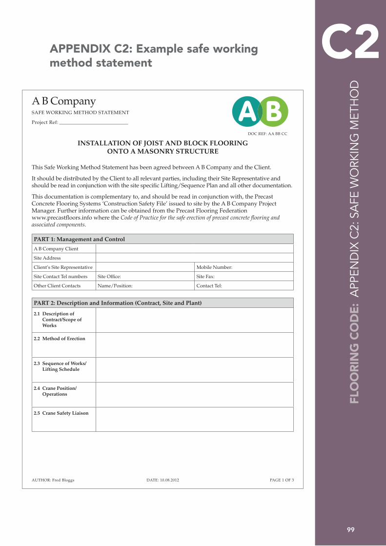
99
FLO
OR
ING
CO
DE
: A
PPEN
DIX
C2:
SA
FE W
ORK
ING
MET
HO
D
C2 APPENDIX C2: Example safe working method statement
A B CompanySAFE WORKING METHOD STATEMENT
Project Ref:
DOC REF: AA BB CC
PAGE 1 OF 3AUTHOR: Fred Bloggs DATE: 10.08.2012
INSTALLATION OF JOIST AND BLOCK FLOORING ONTO A MASONRY STRUCTURE
This Safe Working Method Statement has been agreed between A B Company and the Client.
It should be distributed by the Client to all relevant parties, including their Site Representative and should be read in conjunction with the site specific Lifting/Sequence Plan and all other documentation.
This documentation is complementary to, and should be read in conjunction with, the Precast Concrete Flooring Systems ‘Construction Safety File’ issued to site by the A B Company Project Manager. Further information can be obtained from the Precast Flooring Federation www.precastfloors.info where the Code of Practice for the safe erection of precast concrete flooring and associated components.
PART 1: Management and Control
A B Company Client
Site Address
Client’s Site Representative Mobile Number:
Site Contact Tel numbers Site Office: Site Fax:
Other Client Contacts Name/Position: Contact Tel:
PART 2: Description and Information (Contract, Site and Plant)
2.1 Description of Contract/Scope of Works
2.2 Method of Erection
2.3 Sequence of Works/Lifting Schedule
2.4 Crane Position/Operations
2.5 Crane Safety Liaison

100
A B CompanySAFE WORKING METHOD STATEMENT
Project Ref:
DOC REF: AA BB CC
PAGE 2 OF 3AUTHOR: Fred Bloggs DATE: 10.08.2012
2.6 Refusal to Sign off Crane Stands
2.7 Deliveries and Site Access
PART 3: Stability and Bearings
3.1 Stability and Bearings
PART 4: Personnel
4.1 Site Induction/ Method Statement Review
4.2 Training/Competence
4.3 Other Site Operations/ 3rd Parties
4.4 Use of Mobile Phones
PART 5: Health and Safety Management and Control Measures
5.1 Personal Protective Equipment
5.2 Access to Work Area
5.3 Positioning of Units

101
FLO
OR
ING
CO
DE
: A
PPEN
DIX
C2:
SA
FE W
ORK
ING
MET
HO
D
C2A B CompanySAFE WORKING METHOD STATEMENT
Project Ref:
DOC REF: AA BB CC
PAGE 3 OF 3AUTHOR: Fred Bloggs DATE: 10.08.2012
A B CompanySAFE WORKING METHOD STATEMENT
Project Ref: A B5.4 Working at Height
5.5 Leading Edge Protection
5.6 Accidents and incidents
5.7 Welfare Facilities
5.8 Recovery From Falls/First Aid
5.9 Site Management
5.10 Amendments to the Method Statement
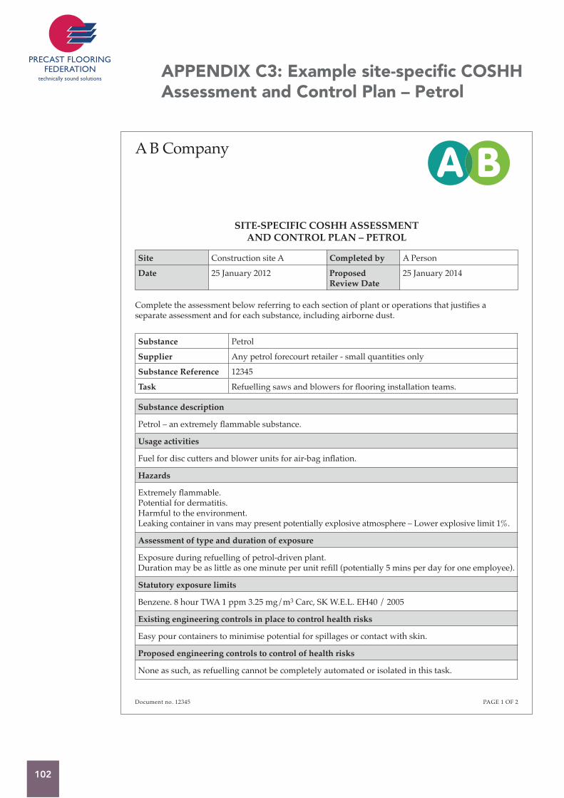
102
APPENDIX C3: Example site-specific COSHH Assessment and Control Plan – Petrol

103
FLO
OR
ING
CO
DE
: A
PPEN
DIX
C3:
CO
SHH
C3

104
APPENDIX C4: Example site-specific COSHH Assessment and Control Plan – Wet concrete
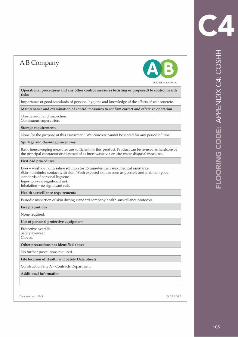
105
FLO
OR
ING
CO
DE
: A
PPEN
DIX
C4:
CO
SHH
C4
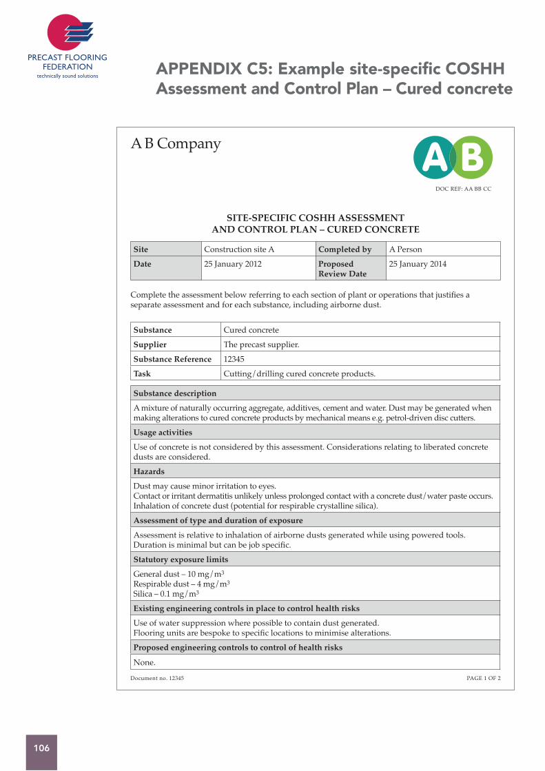
106
APPENDIX C5: Example site-specific COSHH Assessment and Control Plan – Cured concrete
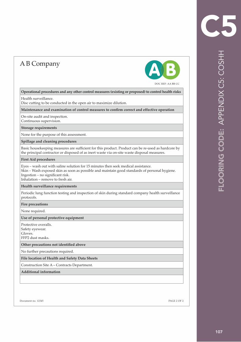
107
FLO
OR
ING
CO
DE
: A
PPEN
DIX
C5:
CO
SHH
C5

108
APPENDIX C6: Example guidance on minimum standards for PPE

Page left blank intentionally

60 Charles StreetLeicesterLE1 1PETel: 0116 253 6161Fax: 0116 251 4568 Email: [email protected]