Embed Size (px)
Citation preview
PRECAST CONCRETE
TRAFFIC BARRIERS
OUTLINE
• Purpose of Traffic Barrier• Specifications• NCHRP 350 & Requirements• Types of Precast Concrete Barriers• Precast Advantage & Cost Savings • Quality Considerations
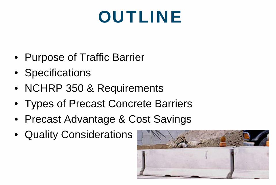
PURPOSE of TRAFFIC BARRIER• Reduce the risk of an out-of-control vehicle crossing the
median and colliding with opposing traffic or roadway workers.
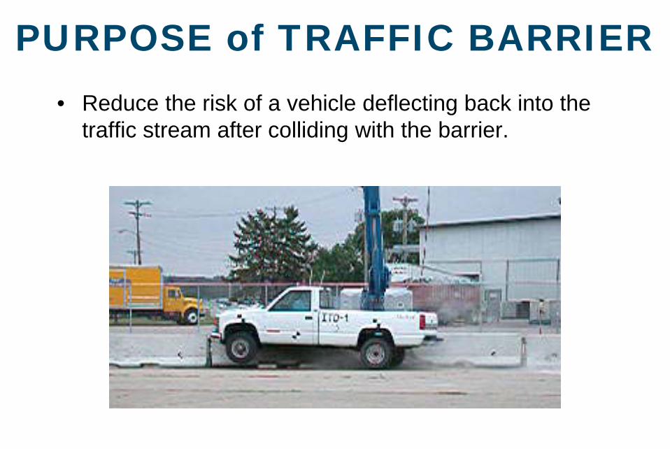
PURPOSE of TRAFFIC BARRIER• Reduce the risk of a vehicle deflecting back into the
traffic stream after colliding with the barrier.
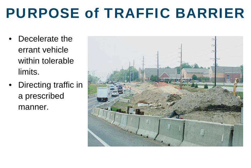
PURPOSE of TRAFFIC BARRIER• Decelerate the
errant vehicle within tolerable limits.
• Directing traffic in a prescribed manner.
PURPOSE of TRAFFIC BARRIER
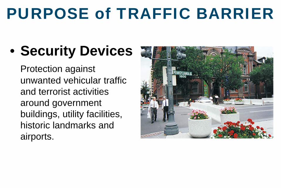
• Security DevicesProtection against unwanted vehicular traffic and terrorist activities around government buildings, utility facilities, historic landmarks and airports.
APPLICABLE STANDARDS
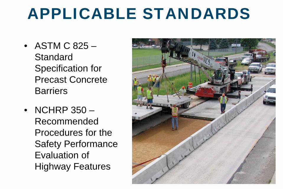
• ASTM C 825 –Standard Specification for Precast Concrete Barriers
• NCHRP 350 –Recommended Procedures for the Safety Performance Evaluation of Highway Features
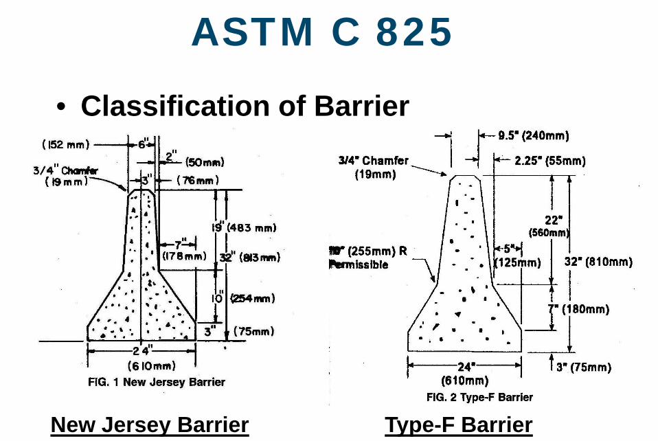
ASTM C 825
• Classification of Barrier
New Jersey Barrier Type-F Barrier
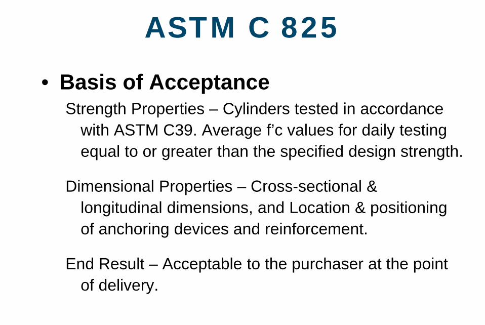
ASTM C 825
• Basis of AcceptanceStrength Properties – Cylinders tested in accordance
with ASTM C39. Average f’c values for daily testing equal to or greater than the specified design strength.
Dimensional Properties – Cross-sectional & longitudinal dimensions, and Location & positioning of anchoring devices and reinforcement.
End Result – Acceptable to the purchaser at the point of delivery.
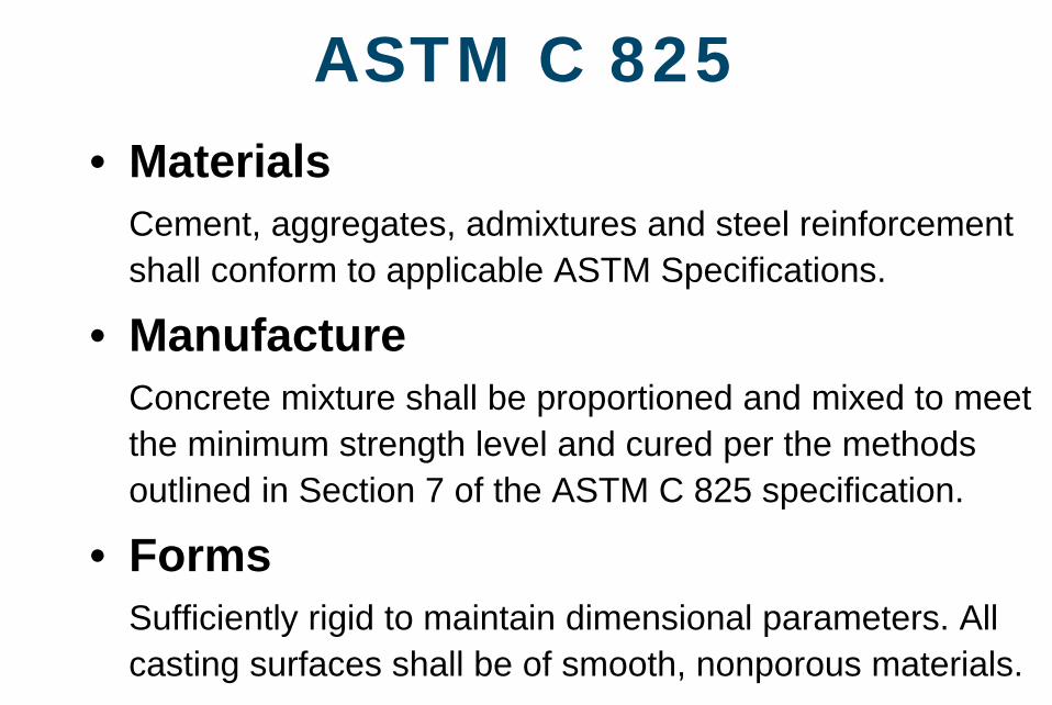
ASTM C 825• Materials
Cement, aggregates, admixtures and steel reinforcement shall conform to applicable ASTM Specifications.
• ManufactureConcrete mixture shall be proportioned and mixed to meet the minimum strength level and cured per the methods outlined in Section 7 of the ASTM C 825 specification.
• FormsSufficiently rigid to maintain dimensional parameters. All casting surfaces shall be of smooth, nonporous materials.
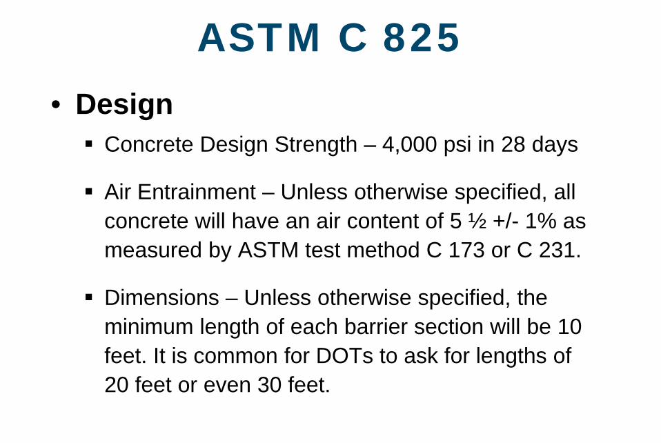
ASTM C 825• Design
Concrete Design Strength – 4,000 psi in 28 days
Air Entrainment – Unless otherwise specified, all concrete will have an air content of 5 ½ +/- 1% as measured by ASTM test method C 173 or C 231.
Dimensions – Unless otherwise specified, the minimum length of each barrier section will be 10 feet. It is common for DOTs to ask for lengths of 20 feet or even 30 feet.
ASTM C 825• Design
Steel Reinforcement – Unless designated by the purchaser, reinforcement shall be designed by the producer and be sufficient to permit handling, delivery and placement of sections without damage.
• Minimum concrete cover is 2.0 inches, except for end sections where cover may be less. See applicable project or ASTM specifications for specific details.
• Shall be assembled as a cage with sufficient mat and bar to maintain shape during casting.
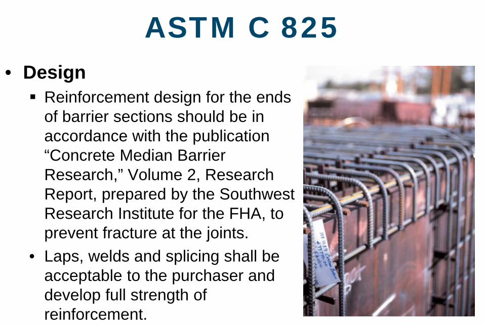
ASTM C 825• Design
Reinforcement design for the ends of barrier sections should be in accordance with the publication “Concrete Median Barrier Research,” Volume 2, Research Report, prepared by the Southwest Research Institute for the FHA, to prevent fracture at the joints.
• Laps, welds and splicing shall be acceptable to the purchaser and develop full strength of reinforcement.
ASTM C 825• Design
Concrete Finishing – Shall be at the option of the producer, produce a finish comparable to the steel form finish and be uniform for all sections in the contract lot.
Lifting Devices – Shall not be cast into the side surfaces of the barrier product.
Anchorage to prevent lateral movement of the barrier shall consist of dowels, keyway joints or interlocking devices as may be specified by the purchaser.
ASTM C 825• Physical Requirements
Compression Testing – Identified with Barrier Sections
• 2 cylinders for each 25 yd3, or a minimum of 2 cylinders per day’s production in accordance with ASTM C31, “Standard Practice for Making and Curing Concrete Test Specimens in the Field,” except when otherwise specified.
• Compressive Strength per ASTM C39, “Compressive Strength of Cylindrical Specimens.”
ASTM C 825• Permissible Dimensional Tolerances
Cross-sectional dimensions shall not vary from design by more than ¼ inch. Vertical centerline shall not be out of plumb by more than ¼ inch.
Longitudinal dimensions shall not vary from design by more than ¼ inch in 10 feet of barrier section and not exceed ¾ inch per section.
Location of anchoring is specified by purchaser.
NCHRP 350
• Summary• Federal Highway Administration (FHWA) issued a
guidance memo in July 1997 requiring crash testing of all work zone devices on the National Highway System. This crash testing is outlined in NCHRP 350 (National Cooperative of Highway Research Programs).
• Visit the Web site at http://safety.fhwa.dot.gov/roadway_dept/road_hardware/nchrp_350.htm
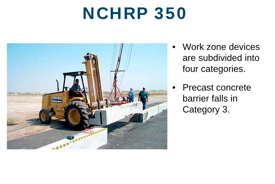
NCHRP 350
• Work zone devices are subdivided into four categories.
• Precast concrete barrier falls in Category 3.
NCHRP 350
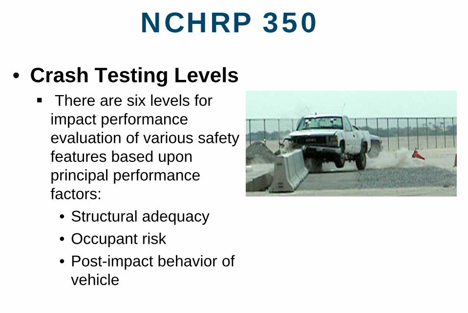
• Crash Testing LevelsThere are six levels for impact performance evaluation of various safety features based upon principal performance factors:
• Structural adequacy• Occupant risk• Post-impact behavior of
vehicle
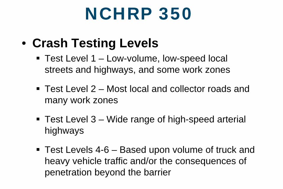
NCHRP 350• Crash Testing Levels
Test Level 1 – Low-volume, low-speed local streets and highways, and some work zones
Test Level 2 – Most local and collector roads and many work zones
Test Level 3 – Wide range of high-speed arterial highways
Test Levels 4-6 – Based upon volume of truck and heavy vehicle traffic and/or the consequences of penetration beyond the barrier
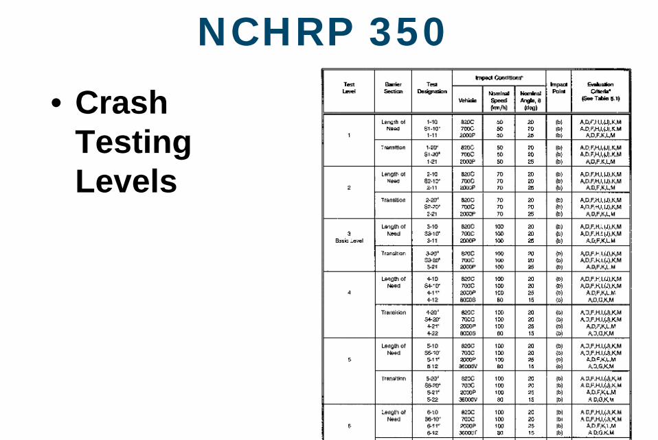
NCHRP 350• Crash
Testing Levels
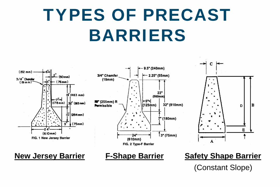
TYPES OF PRECAST BARRIERS
New Jersey Barrier Safety Shape BarrierF-Shape Barrier(Constant Slope)
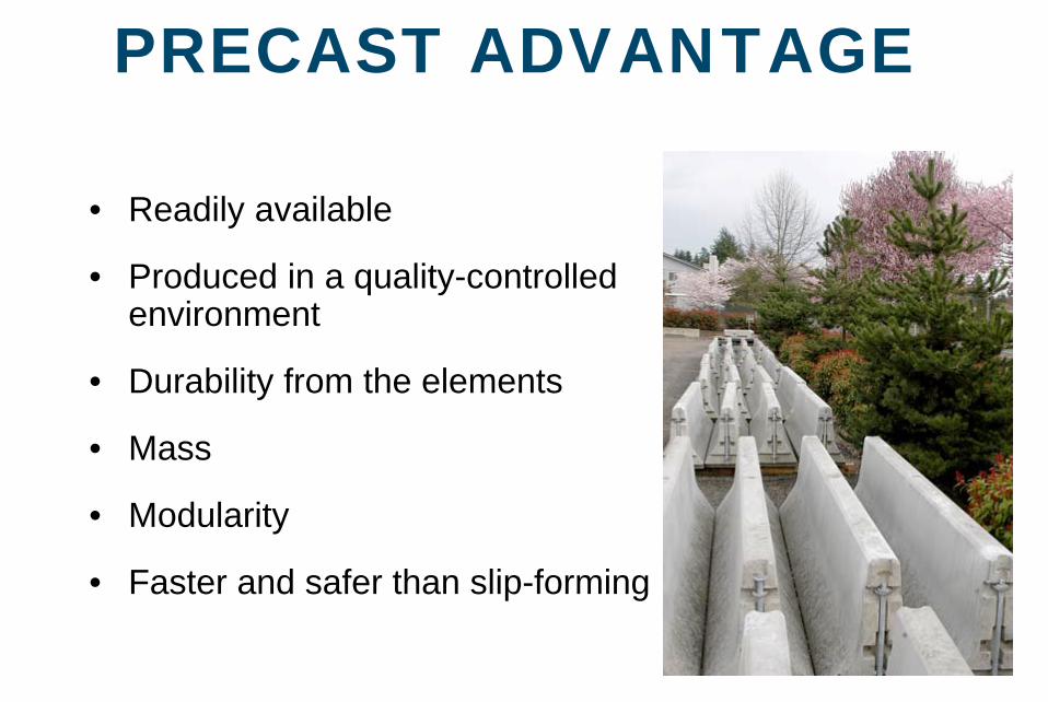
PRECAST ADVANTAGE
• Readily available
• Produced in a quality-controlled environment
• Durability from the elements
• Mass
• Modularity
• Faster and safer than slip-forming
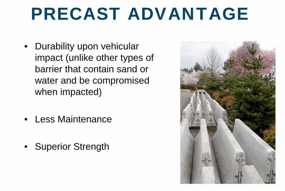
PRECAST ADVANTAGE• Durability upon vehicular
impact (unlike other types of barrier that contain sand or water and be compromised when impacted)
• Less Maintenance
• Superior Strength
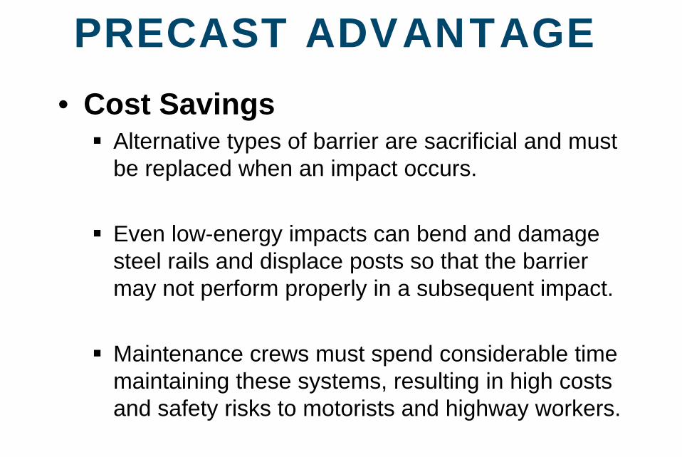
PRECAST ADVANTAGE• Cost Savings
Alternative types of barrier are sacrificial and must be replaced when an impact occurs.
Even low-energy impacts can bend and damage steel rails and displace posts so that the barrier may not perform properly in a subsequent impact.
Maintenance crews must spend considerable time maintaining these systems, resulting in high costs and safety risks to motorists and highway workers.
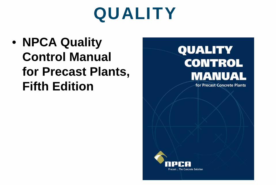
QUALITY• NPCA Quality
Control Manual for Precast Plants, Fifth Edition
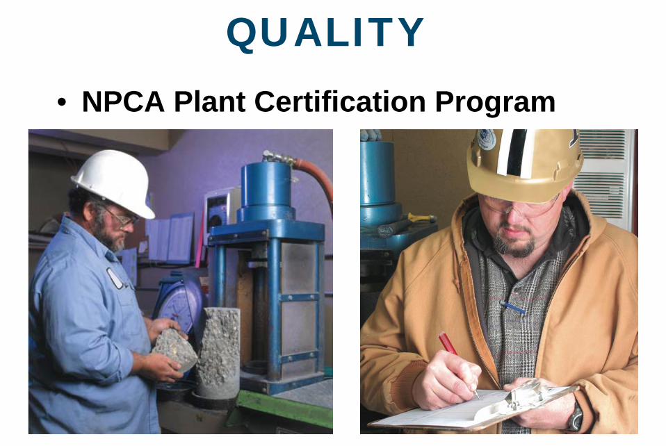
QUALITY• NPCA Plant Certification Program