Embed Size (px)
Citation preview
Nov 2
018
4.0
1 - E
xa
mple
Wyo. Proj.
Sheet of Sheets
0433022 &
P533034 Comb
BRIDGE PROGRAM
WYOMING DEPARTMENT OF TRANSPORTATION
DESIGN
DETAIL
REVISIONS
ofQTY'S
Design Section
Drwg No. Sheet 1 4
REVIEW
APPROVAL
HHH PPPQ R Stuv
0433022_pl1.dgn
0433022
SINGLE BARREL 8'-0" X 8'-0"
PRECAST CONCRETE BOX CULVERTS
VARIOUS LOCATIONS
GILLETTE - MONTANA STATE LINE
CORRAL CREEK SECTION
CAMPBELL COUNTY
DESIGN DATA
ITEM NO. ITEM UNITQUANTITY
TOTALESTIMATE
202.03250
212.03900 CY
LS
513.00005 CLASS A CONCRETE LS LUMP SUM
514.00015 LS LUMP SUM
PERVIOUS BACKFILL MATERIAL
REINFORCING STEEL
X
502.01808 FT
900.60000 LS LUMP SUMCONTRACTOR QUALITY CONTROL (CONCRETE)
INDEX OF STRUCTURES
STATION ROUTE RMNUMBER
STRUCTURE
INTERSECTED
FEATURELOCATION
ESTIMATED QUANTITIES
REMOVAL OF RC BOX CULVERTS
PRECAST BOX CULVERTS 8 X 8 ft
LUMP SUM X EA
X
LUMP SUM
STA 438+50CODE 11-CHC
STA 674+27
X EA
X
P-0007
X CY X CY
X LB X LB
X X
Sectio
n 4.0
1 - Prelim
inary
PRELIMINARY
LOADING:
REINFORCED CONCRETE: Load and Resistance Factor Design -
f'
ADT: 940 (Year 2020)
Dead Load:
Live Load:
APPROACH ROADWAY WIDTH: 36'-0"
8th Edition.
SPECIFICATIONS: AASHTO LRFD Bridge Design Specifications,
fy
c
= 60,000 psi (Grade 60)
= 4000 psi
Reinforcing Steel
Class A Concrete
Lateral earth pressure:
Vertical earth pressure:
Design fill:
Lateral live load surcharge: 2 ft earth or 72 psf
HL93
72 pcf
120 pcf
3.6 ft at Sta 674+27
2.6 ft at Sta 438+50
f'
fy
c
Reinforcing Steel
Class A Concrete
PRECAST CONCRETE: Load and Resistance Factor Design -
= 60,000 psi (Grade 60)
= 5000 psi
438+50
674+27
M-LUW-C
M-LTW-C132.79
128.32ML43B
ML43B
Unnamed Draw
Cedar Creek
Sec 25, T52N, R72W
Sec 1, T52N, R72W
Nov 2
018
4.0
1 - E
xa
mple
Wyo. Proj.
Sheet of Sheets
0433022 &
P533034 Comb
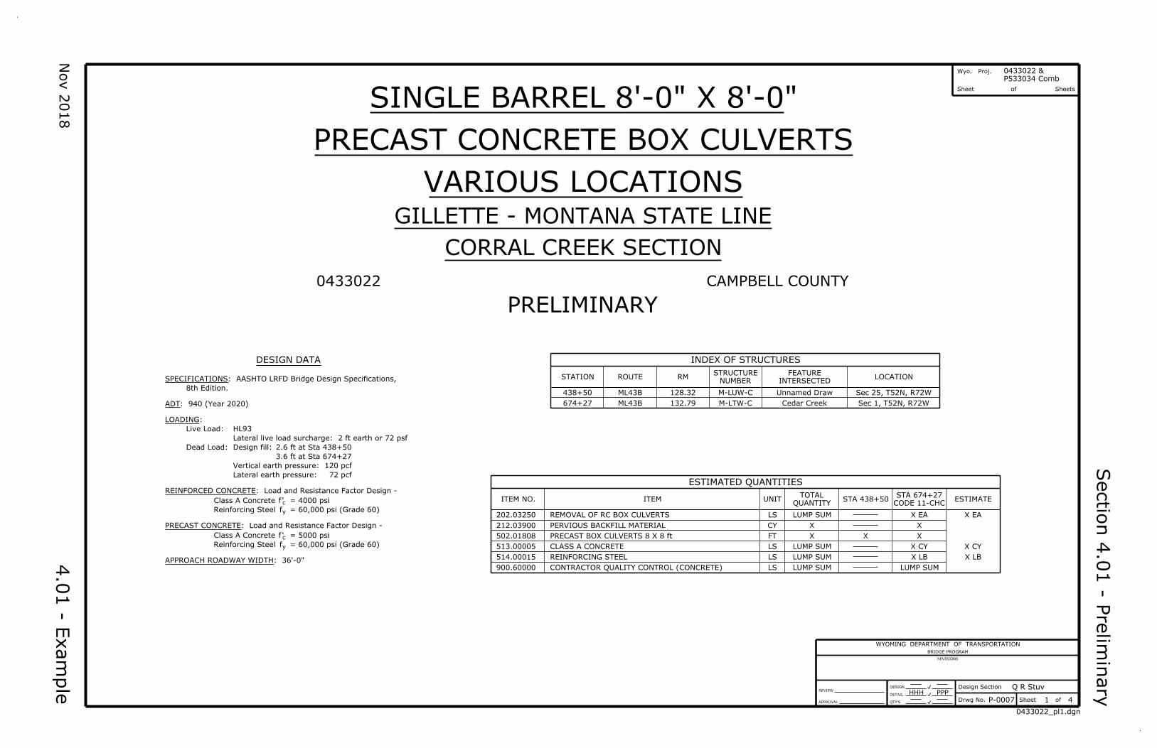
GENERAL NOTES
BAR MARKS
Straight Bars Bent Bars
Size Length Designation
508-3 4A2
Size
DESIGN
DETAIL
Design Section
ofSheetDrwg No.QTY'S
REVIEW
APPROVAL
REVISIONS
WYOMING DEPARTMENT OF TRANSPORTATION
BRIDGE PROGRAM
Q R Stuv
2
HHH
4
PPP
SINGLE BARREL 8'-0" X 8'-0"
PRECAST CONCRETE BOX CULVERTS
VARIOUS LOCATIONS
Gillette - Montana State Line
Corral Creek Section
0433022 Cl
REFERENCES
STREAM DATA - STA 674+27
Sectio
n 4.0
1 - Prelim
inary
PRELIMINARY GENERAL NOTES
P-0007
0433022_pl2.dgn
Construction, 2010 Edition.
SPECIFICATIONS: WYDOT Standard Specifications for Road and Bridge
are out to out. Ensure bars marked with an asterisk (*) are coated.
face of reinforcing steel is 2" unless noted. Dimensions for bent bars
(Grade 60) for all bars, including ties and stirrups. Concrete cover to
REINFORCING STEEL: Ensure reinforcing steel conforms to ASTM A 615
Drainage Area
Description of Channel Material
Drift Potential
Method of Analysis
Flood of Record
Q
Q
Design Frequency
Design Discharge
Ordinary High Water Elevation
Headwater Elevation
Source of Discharge
Q
QReview Discharge
Supplementary Specifications:
SS-100K Adjustment for Structural Steel
SS-500G
WYDOT Plans:
Control and Quality Acceptance
Structural Concrete with Quality
Sheet No.
Standard Plans:
Sta 674+27
1 of 1
206-1A Culvert and Trench Excavation
3.4 Sq Mi
0.30%Structure Slope
Sand, clay, and scoria
Insignificant
3981.5 ft
3990.7 ft25
100
Outlet Velocity 12.5 fps
250 Year
25
100
655 cfs
1290 cfs
Floodflow Characteristics of Wyoming Streams
CDS
Unknown
3992.5 ft
vertical : horizontal.
DIMENSIONS: Longitudinal dimensions are along flow line. Slopes areConcrete.
necessary for the eyebolts is incidental to the contract pay item Class A
EYEBOLTS: Use galvanized bar conforming to ASTM A 709 (Grade 36). Work
incidental to the contract pay item Class A Concrete.
WEEP HOLE ASSEMBLIES: Work necessary for the weep hole assemblies is
expansion joint filler is incidental to the contract pay item Class A Concrete.
PREFORMED EXPANSION JOINT FILLER: Work necessary for the preformed
Precast Box Culverts 8 x 8 ft.
necessary for the joint sealant is incidental to the contract pay item
JOINT SEALANT: Use joint sealant conforming to AASHTO M 198. Work
1 ½" and 1" to other reinforcing steel unless noted.
The minimum concrete cover to the face of the main reinforcing steel is
the seal and signature of a professional engineer.
Ensure the title pages of the design computations and shop plans bear
PRECAST BOX CULVERTS: Design precast boxes for the loading specified.
to the contract pay item Precast Box Culverts 8 x 8 ft.
Work necessary for the precast parapets and cutoff walls is incidental
the contract pay item Precast Box Culverts 8 x 8 ft.
precast sloped end sections is included in the estimated quantity for
SLOPED END SECTIONS, PARAPETS, AND CUTOFF WALLS: The length of
Structure No. CHC.
double barrel 10'-0" x 10'-0" x 41'-0" reinforced concrete box culvert,
REMOVAL OF RC BOX CULVERTS: At Sta 674+27, remove the existing
Culverts.
520 CY and is incidental to the contract pay item Removal of RC Box
removal of the existing culvert and excavation for the new culvert, is
The estimated quantity of culvert excavation at Sta 674+27, including
Box Culverts 8 x 8 ft.
Sta 438+15 is 240 CY and is incidental to the contract pay item Precast
CULVERT EXCAVATION: The estimated quantity of culvert excavation at
bonding compound is incidental to the contract pay item Class A Concrete.
manufacturer's recommendations. Work necessary for the epoxy resin
to Subsection 810.6, Epoxy Resin. Mix and apply in accordance with the
remove by sandblasting and reapply. Use bonding compound conforming
compound. If the bonding compound gels before concrete placement,
of the precast culvert end sections and coat with epoxy resin bonding
EPOXY RESIN BONDING COMPOUND: At Sta 674+27, Clean the exposed ends
has been removed.
Engineer in writing within 14 calendar days after the existing culvert
BRIDGE OFFICE NOTIFICATION: The engineer will notify the State Bridge
Bridge Drwg No. 2208
DESIGN
DETAIL
Design Section
ofSheetDrwg No.QTY'S
REVIEW
APPROVAL
REVISIONS
WYOMING DEPARTMENT OF TRANSPORTATION
BRIDGE PROGRAM
Q R Stuv
VARIOUS LOCATIONS
Sectio
n 4.0
1 - Prelim
inary
Wyo. Proj.
Sheet of Sheets
Nov 2
018
4.0
1 - E
xa
mple
PRELIMINARY LAYOUT
3
P433034 Comb
0433022 &
SINGLE BARREL 8'-0" X 8'-0"
PRECAST CONCRETE BOX CULVERTS
Gillette - Montana State Line
Corral Creek Section
P-0007 4
04330220_1pl3.dgn
HHH PPP
0433022 Cl
N
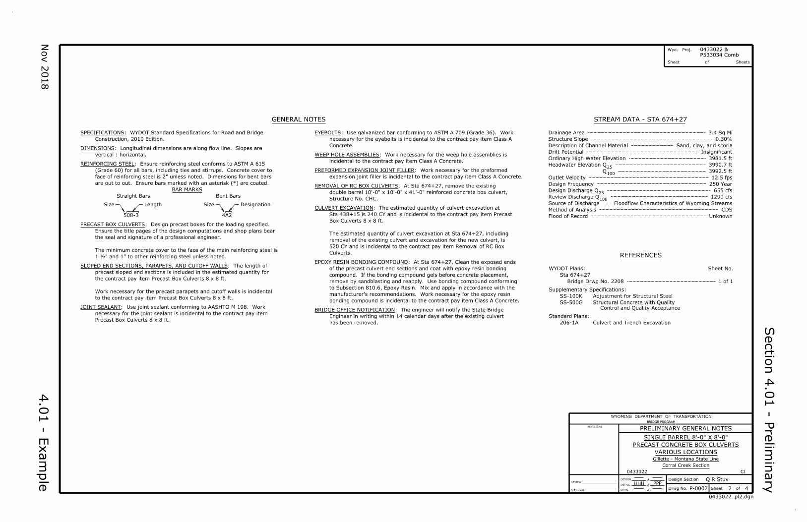
110'-0"
57'-0" 53'-0"
100'-0" to Existing Highway R/W Line 100'-0" to Existing Highway R/W Line
UNNAMED
DRAW
Ë C
ulv
ert
Ë Survey
439+00
438+00
N 2
0°09'3
0.7
" W
90°
Sta 438+50.00
Ë CulvertT
O G
ILLE
TT
E
TO M
ON
TA
NA
ST
AT
E LIN
E
A
A B
B
LOCATION PLAN
Precast Parapet (Typ)
Elev 4068.75
Wall (Typ)
Precast Cutoff
16'-0" 78'-0" 16'-0"
Precast Sloped End Sections Precast Culvert Sections Precast Sloped End Sections
Flow Line Slope 1.36% Elev 4070.25
LONGITUDINAL SECTION
8'-0"
Varies8'-0"
8'-0"
Jt (Typ)
Opt Const
Wall
Cutoff
Precast
SECTION A-A
SECTION B-B
25'-0" Clear Zone
12'-0" 12'-0" 6'-0"
25'-0" Clear Zone
6'-0"
1:81:8
ShoulderTraveled WayTraveled WayShoulder
Ë Survey
Slope 2% Slope 2%
Profile GradeCover Coat Material
16"± Crushed Base
Biaxial Geogrid (Typ)
4 ½"± Hot Plant Mix
STA 438+50.00
TYPICAL ROADWAY SECTION
Nov 2
018
Wyo. Proj.
Sheet of Sheets
P433034 Comb
0433022 &
DESIGN
DETAIL
Design Section
ofSheetDrwg No.QTY'S
REVIEW
APPROVAL
REVISIONS
WYOMING DEPARTMENT OF TRANSPORTATION
BRIDGE PROGRAM
Q R Stuv
VARIOUS LOCATIONS
Sectio
n 4.0
1 - Prelim
inary
PRELIMINARY LAYOUT
SINGLE BARREL 8'-0" X 8'-0"
PRECAST CONCRETE BOX CULVERTS
Gillette - Montana State Line
Corral Creek Section
P-0007 4
04330220_1pl4.dgn
HHH PPP
0433022 Cl
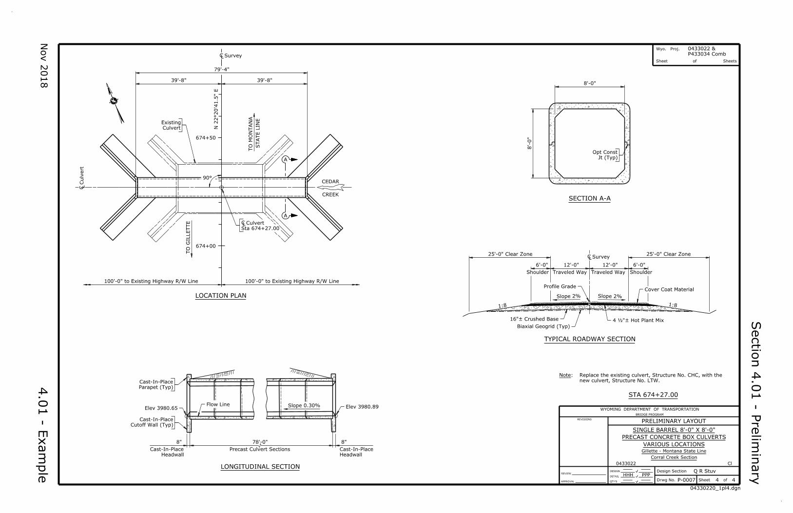
STA 674+27.00
4.0
1 - E
xa
mple
25'-0" Clear Zone
12'-0" 12'-0" 6'-0"
25'-0" Clear Zone
6'-0"
1:81:8
ShoulderTraveled WayTraveled WayShoulder
Ë Survey
Slope 2% Slope 2%
Profile GradeCover Coat Material
16"± Crushed Base
Biaxial Geogrid (Typ)
4 ½"± Hot Plant Mix
TYPICAL ROADWAY SECTION
8'-0"
8'-0"
Jt (Typ)
Opt Const
SECTION A-A
4
N
39'-8"
79'-4"
39'-8"
100'-0" to Existing Highway R/W Line 100'-0" to Existing Highway R/W Line
674+00
674+50
90°CEDAR
CREEK
A
AN 2
2°20'4
1.5
" E
TO M
ON
TA
NA
ST
AT
E LIN
E
TO G
ILLE
TT
E
Sta 674+27.00
Ë Culvert
Culvert
Existing
Ë Survey
Ë C
ulv
ert
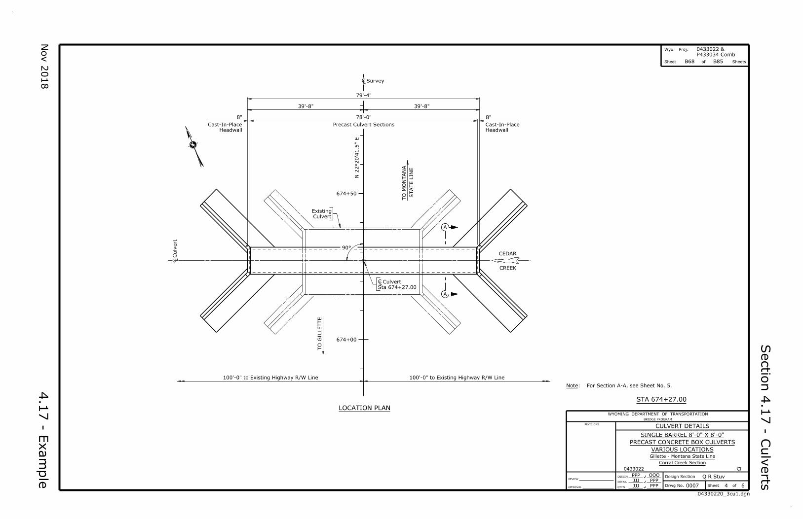
LOCATION PLAN
78'-0"
Precast Culvert Sections
8"
Headwall
Cast-In-Place
8"
Headwall
Cast-In-Place
Slope 0.30%
Parapet (Typ)
Cast-In-Place
Elev 3980.65
Cutoff Wall (Typ)
Cast-In-Place
Flow LineElev 3980.89
LONGITUDINAL SECTION
Note:
new culvert, Structure No. LTW.
Replace the existing culvert, Structure No. CHC, with the
Nov 2
018
Sectio
n 4.0
2 - G
eneral N
ote
s
4.0
2 - E
xa
mple
Wyo. Proj.
Sheet of Sheets
0433022 &
B65 B85
P533034 Comb
BRIDGE PROGRAM
WYOMING DEPARTMENT OF TRANSPORTATION
DESIGN
DETAIL
REVISIONS
ofQTY'S
Design Section
Drwg No. Sheet 1 6
REVIEW
APPROVAL
HHH PPPQ R Stuv
0007
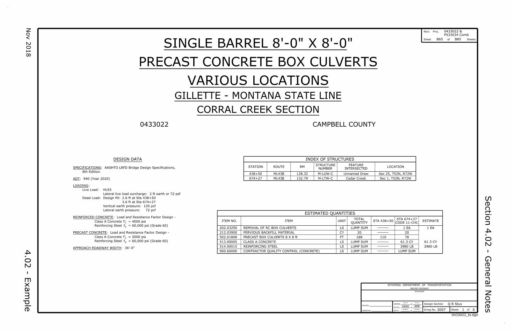
0433022
SINGLE BARREL 8'-0" X 8'-0"
PRECAST CONCRETE BOX CULVERTS
VARIOUS LOCATIONS
GILLETTE - MONTANA STATE LINE
CORRAL CREEK SECTION
CAMPBELL COUNTY
DESIGN DATA
ITEM NO. ITEM UNITQUANTITY
TOTALESTIMATE
202.03250
212.03900 CY
LS
513.00005 CLASS A CONCRETE LS LUMP SUM
514.00015 LS LUMP SUM
PERVIOUS BACKFILL MATERIAL
REINFORCING STEEL
20
61.3 CY
502.01808 FT
900.60000 LS LUMP SUMCONTRACTOR QUALITY CONTROL (CONCRETE)
188
INDEX OF STRUCTURES
STATION ROUTE RMNUMBER
STRUCTURE
INTERSECTED
FEATURELOCATION
ESTIMATED QUANTITIES
REMOVAL OF RC BOX CULVERTS
PRECAST BOX CULVERTS 8 X 8 ft
LUMP SUM 1 EA
3980 LB
110
20
61.3 CY
3980 LB
LUMP SUM
STA 438+50CODE 11-CHC
STA 674+27
1 EA
78
0433022_ts.dgn
LOADING:
REINFORCED CONCRETE: Load and Resistance Factor Design -
f'
ADT: 940 (Year 2020)
Dead Load:
Live Load:
APPROACH ROADWAY WIDTH: 36'-0"
8th Edition.
SPECIFICATIONS: AASHTO LRFD Bridge Design Specifications,
fy
c
= 60,000 psi (Grade 60)
= 4000 psi
Reinforcing Steel
Class A Concrete
Lateral earth pressure:
Vertical earth pressure:
Design fill:
Lateral live load surcharge: 2 ft earth or 72 psf
HL93
72 pcf
120 pcf
3.6 ft at Sta 674+27
2.6 ft at Sta 438+50
f'
fy
c
Reinforcing Steel
Class A Concrete
PRECAST CONCRETE: Load and Resistance Factor Design -
= 60,000 psi (Grade 60)
= 5000 psi
438+50
674+27
M-LUW-C
M-LTW-C132.79
128.32ML43B
ML43B
Unnamed Draw
Cedar Creek
Sec 25, T52N, R72W
Sec 1, T52N, R72W
Nov 2
018
Sectio
n 4.0
2 - G
eneral N
ote
s
4.0
2 - E
xa
mple
Wyo. Proj.
Sheet of Sheets
0433022 &
B65 B85
P533034 Comb
0433022_gn.dgn
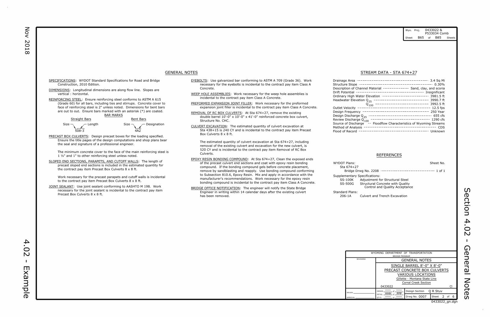
GENERAL NOTES
BAR MARKS
Straight Bars Bent Bars
Size Length Designation
508-3 4A2
Size
DESIGN
DETAIL
Design Section
ofSheetDrwg No.QTY'S
REVIEW
APPROVAL
REVISIONS
WYOMING DEPARTMENT OF TRANSPORTATION
BRIDGE PROGRAM
Q R Stuv
2
GENERAL NOTES
HHH
6
PPP
0007
SINGLE BARREL 8'-0" X 8'-0"
PRECAST CONCRETE BOX CULVERTS
VARIOUS LOCATIONS
Gillette - Montana State Line
Corral Creek Section
0433022 Cl
REFERENCES
STREAM DATA - STA 674+27
Construction, 2010 Edition.
SPECIFICATIONS: WYDOT Standard Specifications for Road and Bridge
are out to out. Ensure bars marked with an asterisk (*) are coated.
face of reinforcing steel is 2" unless noted. Dimensions for bent bars
(Grade 60) for all bars, including ties and stirrups. Concrete cover to
REINFORCING STEEL: Ensure reinforcing steel conforms to ASTM A 615
Drainage Area
Description of Channel Material
Drift Potential
Method of Analysis
Flood of Record
Q
Q
Design Frequency
Design Discharge
Ordinary High Water Elevation
Headwater Elevation
Source of Discharge
Q
QReview Discharge
Supplementary Specifications:
SS-100K Adjustment for Structural Steel
SS-500G
WYDOT Plans:
Control and Quality Acceptance
Structural Concrete with Quality
Sheet No.
Standard Plans:
Sta 674+27
1 of 1
206-1A Culvert and Trench Excavation
3.4 Sq Mi
0.30%Structure Slope
Sand, clay, and scoria
Insignificant
3981.5 ft
3990.7 ft25
100
Outlet Velocity 12.5 fps
250 Year
25
100
655 cfs
1290 cfs
Floodflow Characteristics of Wyoming Streams
CDS
Unknown
3992.5 ft
vertical : horizontal.
DIMENSIONS: Longitudinal dimensions are along flow line. Slopes areConcrete.
necessary for the eyebolts is incidental to the contract pay item Class A
EYEBOLTS: Use galvanized bar conforming to ASTM A 709 (Grade 36). Work
incidental to the contract pay item Class A Concrete.
WEEP HOLE ASSEMBLIES: Work necessary for the weep hole assemblies is
expansion joint filler is incidental to the contract pay item Class A Concrete.
PREFORMED EXPANSION JOINT FILLER: Work necessary for the preformed
Precast Box Culverts 8 x 8 ft.
necessary for the joint sealant is incidental to the contract pay item
JOINT SEALANT: Use joint sealant conforming to AASHTO M 198. Work
1 ½" and 1" to other reinforcing steel unless noted.
The minimum concrete cover to the face of the main reinforcing steel is
the seal and signature of a professional engineer.
Ensure the title pages of the design computations and shop plans bear
PRECAST BOX CULVERTS: Design precast boxes for the loading specified.
to the contract pay item Precast Box Culverts 8 x 8 ft.
Work necessary for the precast parapets and cutoff walls is incidental
the contract pay item Precast Box Culverts 8 x 8 ft.
precast sloped end sections is included in the estimated quantity for
SLOPED END SECTIONS, PARAPETS, AND CUTOFF WALLS: The length of
Structure No. CHC.
double barrel 10'-0" x 10'-0" x 41'-0" reinforced concrete box culvert,
REMOVAL OF RC BOX CULVERTS: At Sta 674+27, remove the existing
Culverts.
520 CY and is incidental to the contract pay item Removal of RC Box
removal of the existing culvert and excavation for the new culvert, is
The estimated quantity of culvert excavation at Sta 674+27, including
Box Culverts 8 x 8 ft.
Sta 438+15 is 240 CY and is incidental to the contract pay item Precast
CULVERT EXCAVATION: The estimated quantity of culvert excavation at
bonding compound is incidental to the contract pay item Class A Concrete.
manufacturer's recommendations. Work necessary for the epoxy resin
to Subsection 810.6, Epoxy Resin. Mix and apply in accordance with the
remove by sandblasting and reapply. Use bonding compound conforming
compound. If the bonding compound gels before concrete placement,
of the precast culvert end sections and coat with epoxy resin bonding
EPOXY RESIN BONDING COMPOUND: At Sta 674+27, Clean the exposed ends
has been removed.
Engineer in writing within 14 calendar days after the existing culvert
BRIDGE OFFICE NOTIFICATION: The engineer will notify the State Bridge
Bridge Drwg No. 2208
Nov 2
018
Wyo. Proj.
Sheet of Sheets
P433034 Comb
0433022 &
DESIGN
DETAIL
Design Section
ofSheetDrwg No.QTY'S
REVIEW
APPROVAL
REVISIONS
WYOMING DEPARTMENT OF TRANSPORTATION
BRIDGE PROGRAM
Q R Stuv
VARIOUS LOCATIONS
3
SINGLE BARREL 8'-0" X 8'-0"
PRECAST CONCRETE BOX CULVERTS
Gillette - Montana State Line
Corral Creek Section
6
JJJ PPP
0433022 Cl
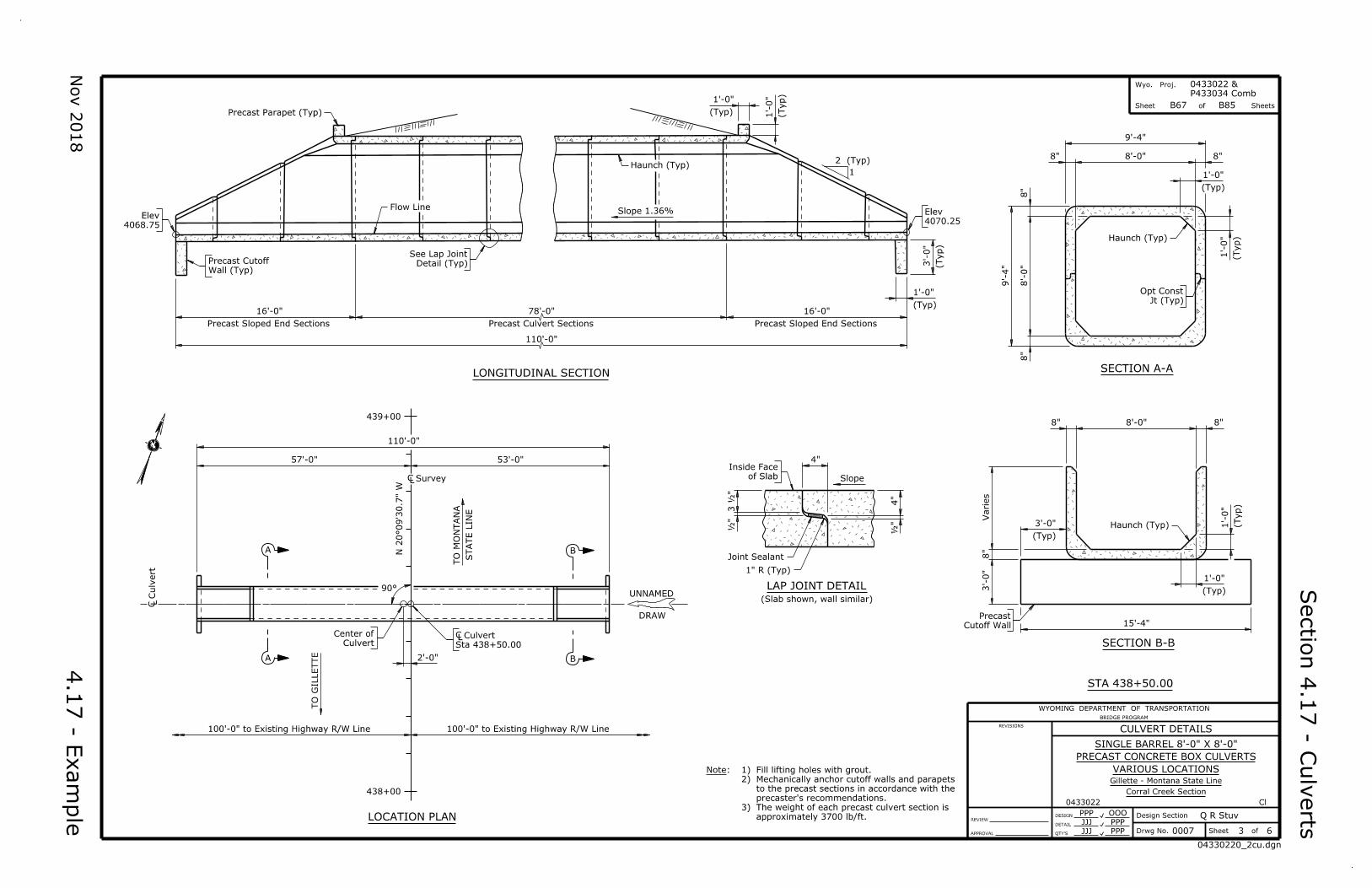
STA 438+50.00
PPP OOO
JJJ PPP 0007
04330220_2cu.dgn
16'-0" 78'-0"
110'-0"
16'-0"
1'-0"
(Typ) 1'-0"
(Typ)
1
2 (Typ)
3'-0"
(Typ)
1'-0"
(Typ)
Precast Sloped End SectionsPrecast Culvert SectionsPrecast Sloped End Sections
Slope 1.36%
Precast Parapet (Typ)
Haunch (Typ)
Flow Line
4068.75
Elev
Wall (Typ)
Precast Cutoff Detail (Typ)
See Lap Joint
4070.25
Elev
LONGITUDINAL SECTION
8'-0"
9'-4"
9'-4"
8'-0"
8"
8"
1'-0"
(Typ)
8"
1'-0"
8" (Typ)
Haunch (Typ)
Jt (Typ)
Opt Const
SECTION A-A
110'-0"
57'-0" 53'-0"
100'-0" to Existing Highway R/W Line100'-0" to Existing Highway R/W Line
UNNAMED
DRAW
N 2
0°09'3
0.7
" W
TO M
ON
TA
NA
ST
AT
E LIN
E
TO G
ILLE
TT
E
90°
A
A B
B2'-0"
439+00
438+00
Culvert
Center of
Sta 438+50.00
Ë Culvert
Ë Survey
Ë C
ulv
ert
N
LOCATION PLAN
4"
4"
Slope
LAP JOINT DETAIL
(Slab shown, wall similar)
1" R (Typ)
Joint Sealant
of Slab
Inside Face
"½
"½
3 ½
"
8'-0"
Varies
3'-0"
8"
3'-0"
15'-4"
(Typ)
1'-0"
1'-0"
(Typ)
(Typ)
8" 8"
Haunch (Typ)
Cutoff Wall
Precast
SECTION B-B
4.1
7 - E
xa
mple
Sectio
n 4.1
7 - C
ulv
erts
Note:
3)
2)
1)
approximately 3700 lb/ft.
The weight of each precast culvert section is
precaster's recommendations.
to the precast sections in accordance with the
Mechanically anchor cutoff walls and parapets
Fill lifting holes with grout.
B67 B85
CULVERT DETAILS
Wyo. Proj.
Sheet of Sheets
Nov 2
018
DESIGN
DETAIL
Design Section
ofSheetDrwg No.QTY'S
REVIEW
APPROVAL
REVISIONS
WYOMING DEPARTMENT OF TRANSPORTATION
BRIDGE PROGRAM
Q R Stuv
P433034 Comb
0433022 &
B85
4.1
7 - E
xa
mple
VARIOUS LOCATIONS
SINGLE BARREL 8'-0" X 8'-0"
PRECAST CONCRETE BOX CULVERTS
Gillette - Montana State Line
Corral Creek Section
6
JJJ PPP
0433022 Cl
PPP OOO
JJJ PPP 0007
Sectio
n 4.1
7 - C
ulv
erts
STA 674+27.00
4
04330220_3cu1.dgn
B68
Culvert
Existing
39'-8"
79'-4"
78'-0"
39'-8"
100'-0" to Existing Highway R/W Line 100'-0" to Existing Highway R/W Line
CEDAR
CREEK
Precast Culvert Sections
8"
Headwall
Cast-In-Place
8"
Headwall
Cast-In-Place
N 2
2°20'4
1.5
" E
674+50
674+00
A
A
TO M
ON
TA
NA
ST
AT
E LIN
E
TO G
ILLE
TT
E
90°
Sta 674+27.00
Ë Culvert
Ë Survey
Ë C
ulv
ert
LOCATION PLAN
N
Note: For Section A-A, see Sheet No. 5.
CULVERT DETAILS
Sectio
n 4.1
7 - C
ulv
erts
DESIGN
DETAIL
Design Section
ofSheetDrwg No.QTY'S
REVIEW
APPROVAL
REVISIONS
WYOMING DEPARTMENT OF TRANSPORTATION
BRIDGE PROGRAM
Q R Stuv
VARIOUS LOCATIONS
SINGLE BARREL 8'-0" X 8'-0"
PRECAST CONCRETE BOX CULVERTS
Gillette - Montana State Line
Corral Creek Section
6
JJJ PPP
0433022 Cl
PPP OOO
JJJ PPP 0007
4.1
7 - E
xa
mple
Wyo. Proj.
Sheet of Sheets
P433034 Comb
0433022 &
B85
Nov 2
018
STA 674+27.00
04330220_3cu2.dgn
5
B69
4"
4"
Slope
LAP JOINT DETAIL
(Slab shown, wall similar)
1" R (Typ)
Joint Sealant
of Slab
Inside Face
"½
"½
3 ½
"
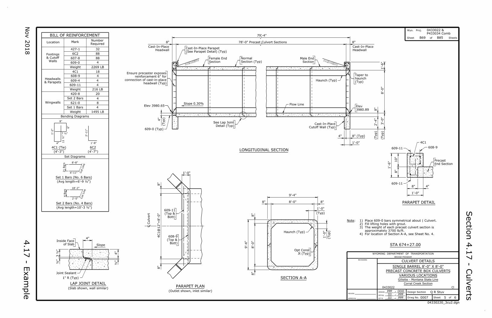
BILL OF REINFORCEMENT
~
~
~
~
Location MarkRequired
Number
32
88
4
88
2269 LBWeight
609-0
607-8
6C2
427-1
Walls
& Cutoff
Footings
& Parapets
Headwalls
4C1
608-9
609-4
609-11
Weight 216 LB
4
4
4
18
20
4
8
1495 LB
Bending Diagrams
Weight
Set 1 Bars
621-0
420-8
Wingwalls
Set Diagrams
4C1 (Tie) 6C2
Set 1 Bars (No. 6 Bars)
Set 2 Bars (No. 4 Bars)
(4'-3") (4'-7")
") ½(Avg length=6'-9
") ½(Avg length=10'-3
4
Set 2 Bars
8"
1'-2"
2'-11"
18'-2"
8'-8"
21 B
ars
4 B
ars
4"
6"
" ½7
" ½
11
1'-8"
4'-11"
2'-5"
Cut
Lin
eCut
Lin
e
79'-4"
78'-0" Precast Culvert Sections
8'-0"
1'-6"
2'-4"
3'-0"
8"
8"
8" (Typ)
1'-0"
Headwall
Cast-In-Place
(Typ)
(Typ)
4"
4"
8"
Headwall
Cast-In-Place
(Typ)
(See Parapet Detail) (Typ)
Cast-In-Place Parapet
Section
Female End
Section (Typ)
Normal
Section
Male End
(Typ)
haunch
Taper to
Haunch (Typ)
3980.89
Elev Flow Line
Cutoff Wall (Typ)
Cast-In-PlaceDetail (Typ)
See Lap Joint
Slope 0.30%Elev 3980.65
609-0 (Typ)
headwall (Typ)
connection of cast-in-place
reinforcement 6" for
Ensure precaster exposes
LONGITUDINAL SECTION
1'-6" 1
0"
8"
8"
1'-0"
4"
609-11
4C1
608-9
End Section
Precast
609-11
PARAPET DETAIL
Haunch (Typ)
Jt (Typ)
Opt Const
9'-4"
8'-0"
9'-4"
8'-0"
8"
8"
1'-0"
(Typ)
8"
1'-0"
8" (Typ)
SECTION A-A
1'-0"
4C1
@12"=
8'-0"
8"
8"
Ë C
ulv
ert
Bott)
(Top &
609-11
Bott)
(Top &
608-9
PARAPET PLAN
(Outlet shown, inlet similar)
Note:
4)
3)
2)
1)
For location of Section A-A, see Sheet No. 4.
approximately 3700 lb/ft.
The weight of each precast culvert section is
Fill lifting holes with grout.
Place 609-0 bars symmetrical about | Culvert.
CULVERT DETAILS
Sectio
n 4.1
7 - C
ulv
erts
DESIGN
DETAIL
Design Section
ofSheetDrwg No.QTY'S
REVIEW
APPROVAL
REVISIONS
WYOMING DEPARTMENT OF TRANSPORTATION
BRIDGE PROGRAM
Q R Stuv
VARIOUS LOCATIONS
SINGLE BARREL 8'-0" X 8'-0"
PRECAST CONCRETE BOX CULVERTS
Gillette - Montana State Line
Corral Creek Section
6
JJJ PPP
0433022 Cl
PPP OOO
JJJ PPP 0007
STA 674+27.00
Wyo. Proj.
Sheet of Sheets
P433034 Comb
0433022 &
B85
Nov 2
018
4.1
7 - E
xa
mple
CULVERT DETAILS
B70
6
04330220_3cu3.dgn
Close joint
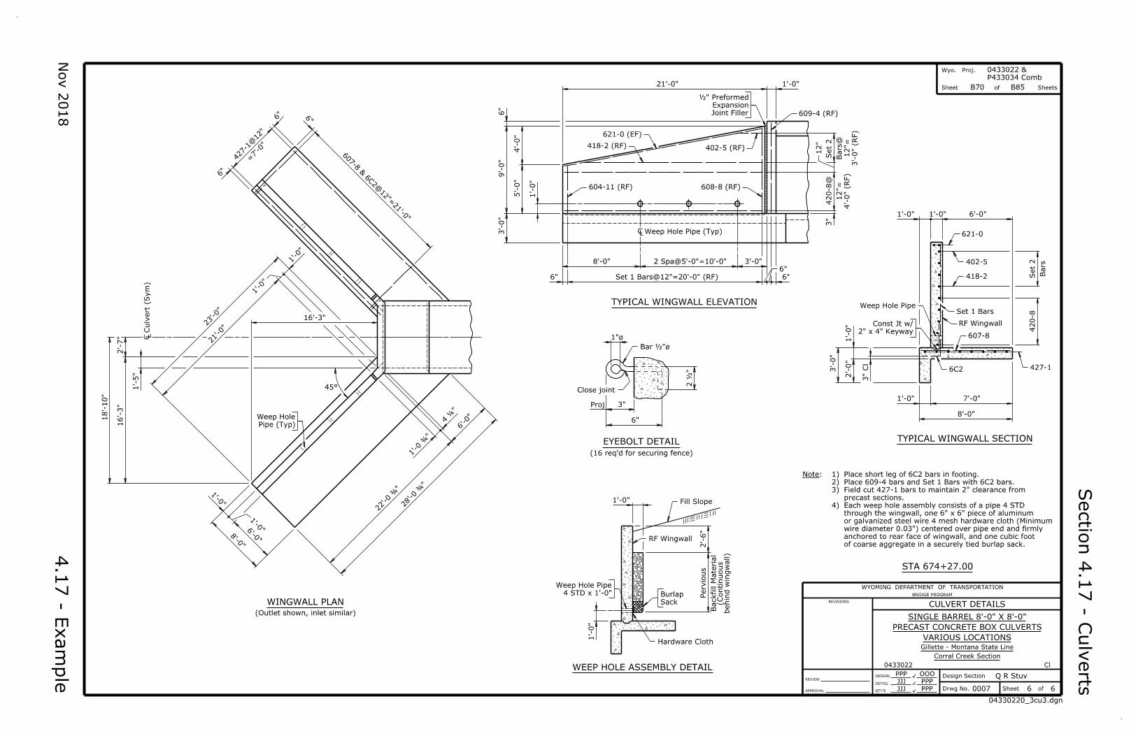
EYEBOLT DETAIL
Proj
(16 req'd for securing fence)
6"
3"
1"ø
½"øBar
2 ½
"
1'-0"
1'-0"
Hardware Cloth
WEEP HOLE ASSEMBLY DETAIL
RF Wingwall
Fill Slope
2'-6"
behin
d win
gwall)
(Continuous
Backfill M
aterial
Pervio
us
Sack
Burlap 4 STD x 1'-0"
Weep Hole Pipe
427-1
@12"
607-8 & 6
C2
@12"=
21'-0
"
23'-0"
21'-0"
16'-3"
6'-0"
6'-0
"8'-0
"
18'-10"
16'-3"
2'-7"
" ¾
22'-0
" ¾
28'-0
=7'-0"
6"
6" 6
"
1'-5"
1'-0"
1'-0"
45°
¾"
1'-0
" ¼
4
1'-0
"
Pipe (Typ)
Weep Hole
1'-0
"
Ë C
ulv
ert (Sy
m)
WINGWALL PLAN
(Outlet shown, inlet similar)
21'-0"
9'-0"
4'-0"
5'-0"
3'-0"
8'-0" 2 Spa@5'-0"=10'-0"
Set 1 Bars@12"=20'-0" (RF)
3'-0"
420-8
@Set
2
4'-0" (
RF)
12"=
3'-0" (
RF)
12"=
Bars
@
1'-0"
6"
6"6"
6"
3"
12"
609-4 (RF)Joint Filler
Expansion
½" Preformed
418-2 (RF)
621-0 (EF)
1'-0"
604-11 (RF)
402-5 (RF)
608-8 (RF)
Ë Weep Hole Pipe (Typ)
TYPICAL WINGWALL ELEVATION
6'-0"1'-0"1'-0"
Set
2420-8
2'-0"
3'-0"
7'-0"
8'-0"
Bars
1'-0"
3" Cl
1'-0"
6C2 427-1
621-0
402-5
418-2
Set 1 Bars
RF Wingwall
607-82" x 4" Keyway
Const Jt w/
Weep Hole Pipe
TYPICAL WINGWALL SECTION
Note:
4)
3)
2)
1)
of coarse aggregate in a securely tied burlap sack.
anchored to rear face of wingwall, and one cubic foot
wire diameter 0.03") centered over pipe end and firmly
or galvanized steel wire 4 mesh hardware cloth (Minimum
through the wingwall, one 6" x 6" piece of aluminum
Each weep hole assembly consists of a pipe 4 STD
precast sections.
Field cut 427-1 bars to maintain 2" clearance from
Place 609-4 bars and Set 1 Bars with 6C2 bars.
Place short leg of 6C2 bars in footing.