Embed Size (px)
Citation preview

Precast Bent System for Precast Bent System for Rapid Construction in Rapid Construction in
Seismic RegionsSeismic Regions
John Stanton ,Marc Eberhard John Stanton ,Marc Eberhard Olafur Haraldsson, Todd Janes, Hung Viet Tran Olafur Haraldsson, Todd Janes, Hung Viet Tran
University of WashingtonUniversity of Washington
WSDOT/ACEC meeting,Seattle, Washington
15 October 2010

Rapid ConstructionRapid ConstructionReduce Traffic Congestion:
– Time = $$ wasted
– Fuel consumed
– Air and noise pollution
Minimize Environmental Impact
Improve Public and Worker Safety

Solutions
OrganizationalOrganizational–– Involve contractor earlyInvolve contractor early
–– Partner with ownerPartner with owner
–– Encourage contractor to innovateEncourage contractor to innovate
FinancialFinancial–– Incentives (A and B contracting)Incentives (A and B contracting)
–– Capital investment by contractorsCapital investment by contractors
PhysicalPhysical–– Prefabricate to reduce onPrefabricate to reduce on--site timesite time

Prefabrication
Existing use of Existing use of precastingprecasting
–– Deck unitsDeck units (some)(some)
–– GirdersGirders (common)(common)
–– BentsBents (some non(some non--seismic)seismic)
–– Foundations and abutmentsFoundations and abutments (rare(rare))
Courtesy of Concrete Technology Corp.Courtesy of Concrete Technology Corp.

Goals of Present Research
Develop a precast bent system that:Develop a precast bent system that:
•• Accelerates constructionAccelerates construction
•• Is easy to constructIs easy to construct
•• Is seismically resistantIs seismically resistant
•• Avoids untried technologies Avoids untried technologies
•• Is economicalIs economical

Construction Procedure
1) Excavate footing.

2) Position and brace precast column.
Construction Procedure

3) Place reinforcement and cast footing.
Construction Procedure

4) Set cap-beam, grout bars into ducts.
Construction Procedure

5) Place girders, diaphragms and deck.
Construction Procedure
Critical connections

Application in Seismic ZonesApplication in Seismic Zones
Fabrication/Transportation: make straight elements.
Site connections: then occur at member intersections.
But: that is where potential plastic hinges occur.

Family of modular connectionsFamily of modular connections
• Different conditions at top and bottom of column.
• Footing type: Spread footing vs. drilled shaft.
• Need for elastic re-centering after an earthquake.
Mix and match connections to make a complete system.
Choice depends on:

Precast Precast
PrestressedPrestressed
CIPCIP
RC (ref) RC (ref)
Precast Precast
RCRC
CapCap--Beam Beam
to Column to Column
Column toColumn to
Spread FootingSpread Footing
Column toColumn to
Drilled ShaftDrilled Shaft
ConnectionsConnections

ColumnColumn--toto--CapCap--BeamBeamConnectionConnection

Cap Beam Connection:Many small bars and ducts
Courtesy: BERGER/ABAM Engineers
Tight tolerances.

Precast columnPrecast column
Precast cap Precast cap beambeam
6 # 18 rebar6 # 18 rebar
8.5” corrugated 8.5” corrugated steel ductssteel ducts
High strength High strength groutgrout
Cap-Beam Connection: Large bars

Key Research QuestionsKey Research Questions
Can #18 bars be anchored in the capCan #18 bars be anchored in the cap--beam for construction and seismic loadsbeam for construction and seismic loads??
How will the system perform seismicallyHow will the system perform seismically??

Question 1 Question 1 –– Anchorage ? Anchorage ?

FullFull--Scale Scale Anchorage TestsAnchorage Tests
Short embedment – bond fails
Long embedment – bar yields and fractures

FullFull--Scale Scale Anchorage TestsAnchorage TestsB
ar
Tests results vs. ACI/AASHTO requirements

Ba
r
FullFull--Scale Scale Anchorage TestsAnchorage Tests
ffyy
ffuu
Tests results vs. FE model

Question Question 22
Seismic Performance? Seismic Performance?


Seismic PerformanceSeismic Performance

-8 -6 -4 -2 0 2 4 6 8-6000
-4000
-2000
0
2000
4000
6000LB-FB
Drift (%)
Equiv
ale
nt
Mom
ent
(kip
-in)
-8 -6 -4 -2 0 2 4 6 8-6000
-4000
-2000
0
2000
4000
6000LB-D1
Drift (%)
Equ
ivale
nt
Mom
ent
(kip
-in
)
-8 -6 -4 -2 0 2 4 6 8-6000
-4000
-2000
0
2000
4000
6000LB-D2
Drift (%)
Equ
ivale
nt
Mo
men
t (k
ip-in
)
-8 -6 -4 -2 0 2 4 6 8-6000
-4000
-2000
0
2000
4000
6000REF
Drift (%)
Eq
uiv
ale
nt
Mom
ent
(kip
-in)
Equivalent Moment vs. DriftEquivalent Moment vs. Drift

LBLB--FB: Bar buckling and spiral fracture at 6.5% driftFB: Bar buckling and spiral fracture at 6.5% drift
Failure Mechanisms Failure Mechanisms

0
1
2
3
4
5
6
7
8
9
Dri
ft L
evel
%
Onset of
Column
Flaking
Onset of
Cap-Beam
Spalling
Onset of
Column
Spalling
Onset of
Bar
Buckling
First Spiral
Fracture
First Bar
Fracture
Damage
Observed Damage
LB-FBLB-D1LB-D2REF

Conclusions: CapConclusions: Cap--Beam ConnectionBeam Connection
Constructability:Constructability:
Construction is fast and easy.Construction is fast and easy.
Potential time savings from avoiding:Potential time savings from avoiding:
•• Cap beam formwork, steel, concrete curing.Cap beam formwork, steel, concrete curing.
Failure occurs in column, not connection.Failure occurs in column, not connection.
Seismic response is same as c.i.p.Seismic response is same as c.i.p.
Seismic Performance:Seismic Performance:

ColumnColumn--toto--FootingFootingConnectionConnection

Footing Connection: Construction
Headed barsHeaded bars

Footing Connection: Headed BarsHeaded BarsStrut and Tie Model.Strut and Tie Model.
Top steel and ties Top steel and ties appear to be appear to be unnecessaryunnecessary

Footing Connection - Conventional
Hooked bars facing outHooked bars facing out(Conventional (Conventional cipcip))
Load transfer is Load transfer is tangential to hook.tangential to hook.
Ineffective!Ineffective!
Strut and Tie Model.Strut and Tie Model.

Spread Footing Connection - Tests:
•• Use footing steel identical to that required for castUse footing steel identical to that required for cast--inin--place.place.
•• Verify vertical punching shearVerify vertical punching shear
•• Verify cyclic lateral load resistance.Verify cyclic lateral load resistance.
Specimen #1Specimen #1
•• Reduce tie steel and “shear friction” steel in footing.Reduce tie steel and “shear friction” steel in footing.
Specimen #2Specimen #2

Spread Footing Connection:Construction

Spread Footing Connection - Test
Vertical Vertical (gravity) load.(gravity) load.
Lateral Lateral (seismic) (seismic) load.load.

Spread Footing Connection - Test
After seismic testing. Foundation undamaged.After seismic testing. Foundation undamaged.
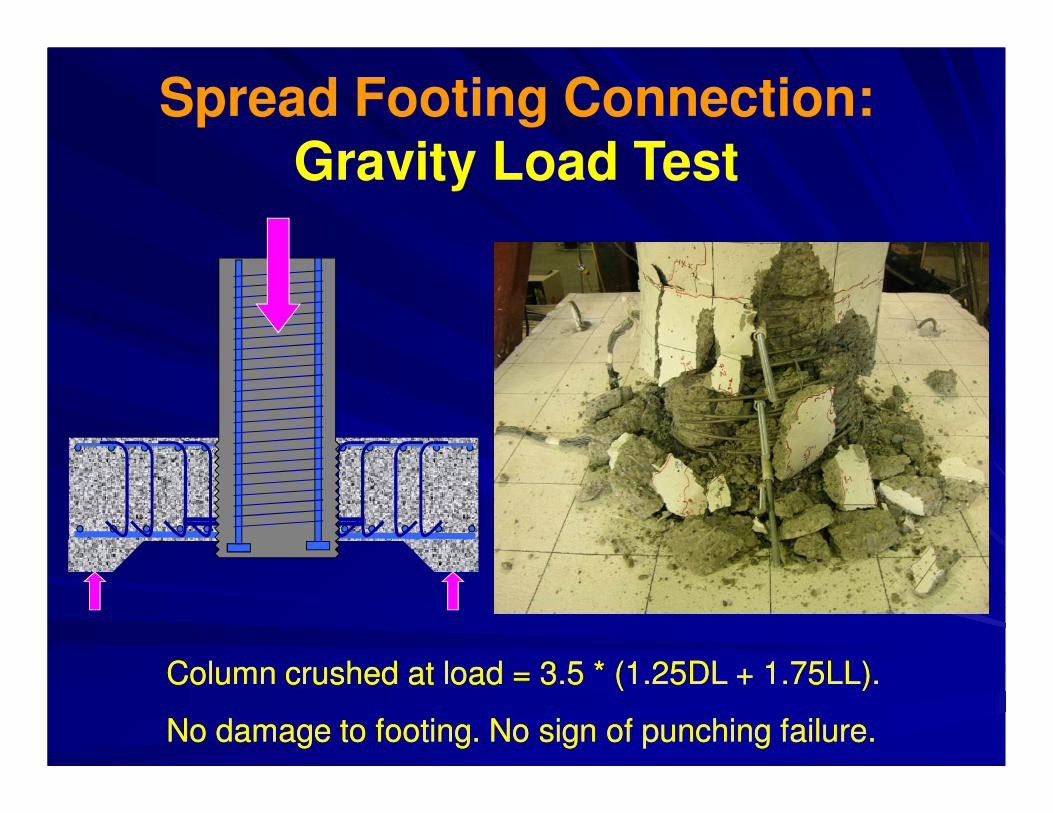
Spread Footing Connection: Gravity Load Test
Column crushed at load = 3.5 * (1.25DL + 1.75LL).Column crushed at load = 3.5 * (1.25DL + 1.75LL).
No damage to footing. No sign of punching failure.No damage to footing. No sign of punching failure.

Spread Footing Connection: Specimen 2 (reduced steel)
Results essentially identical Results essentially identical
to those for Specimen #1.to those for Specimen #1.

Spread Footing ConnectionSpread Footing Connection
Constructability: Easy to fabricate, transport Constructability: Easy to fabricate, transport and erectand erect
-- Column has no projecting bars.Column has no projecting bars.
-- No “formNo “form--saver” bars.saver” bars.
-- No connection alignment.No connection alignment.
-- Reduce or eliminate footing ties & top steel.Reduce or eliminate footing ties & top steel.

Spread Footing ConnectionSpread Footing Connection
Structural Performance:Structural Performance:
•• Headed bars provide better anchorage than Headed bars provide better anchorage than hooked bars facing outwards.hooked bars facing outwards.
•• Failure in column. Footing undamaged in Failure in column. Footing undamaged in lateral load and vertical load tests.lateral load and vertical load tests.
•• Seismic performance as good as, or better Seismic performance as good as, or better than, conventional c.i.p. construction.than, conventional c.i.p. construction.

Implementation
Bid Opening:Bid Opening:
October 14October 14thth

Drilled shaft connectionDrilled shaft connection
CastCast--inin--placeplace PrecastPrecast

Drilled shaft connectionDrilled shaft connectionMoment transfer in Moment transfer in
transition regiontransition region
Horizontal force coupleHorizontal force couple
Big shear on annular region.Big shear on annular region.
Large forces in spiralLarge forces in spiral
Vertical force coupleVertical force couple
Moment transfer by vertical bars.Moment transfer by vertical bars.
Low forces in spiralLow forces in spiral

Drilled shaft connectionDrilled shaft connectionHorizontal or Vertical force couple?Horizontal or Vertical force couple?
Probably depends on L/D ratio of transition region.Probably depends on L/D ratio of transition region.
Large L/D Large L/D ––
horizontal forceshorizontal forces
L
D
Small L/D Small L/D ––
vertical forcesvertical forces
L
D

Drilled shaft connectionDrilled shaft connection
Study variable: Strength of spiral in shaft.Study variable: Strength of spiral in shaft.
�� Specimen #1: same as c.i.p. shaft.Specimen #1: same as c.i.p. shaft.
�� Specimen #2: reduced spiral.Specimen #2: reduced spiral.
Length of Transition region:Length of Transition region:
�� Controlled by vertical bar development.Controlled by vertical bar development.
Specimens being built nowSpecimens being built now

PrePre--Tensioned SystemTensioned System

Pre-Tensioned System -
ComponentsPC capPC cap--beambeam
Sleeved Sleeved strandstrand
Bonded Bonded strandstrandc.i.pc.i.p. .
footingfooting
Bonded Bonded rebarrebar
Cracking Cracking planeplane

Pre-Tensioned System

Pre-Tensioned System

Pre-Tensioned System

Pre-Tensioned System

Pre-Tensioned System

Pre-Tensioned System
1.1.Unbonded prestressing:Unbonded prestressing:
• remains elastic, • re-centers column,• reduces residual displacements.
2.2.PrePre--tensioning solves corrosion problems tensioning solves corrosion problems perceived to exist in postperceived to exist in post--tensioning.tensioning.
3.Pre-tensioning in a plant:• Allows good QC• Eliminates need for special equipment on site (e.g. PT)
4.4.Rebars can be added for energy dissipation.Rebars can be added for energy dissipation.

AcknowledgmentsFunding fromFunding from
•• WSDOTWSDOT
•• TRANSNOWTRANSNOW
•• Valle FoundationValle Foundation
�� FHWA, Highways for Life ProgramFHWA, Highways for Life Program
�� PEERPEER
Ideas (and criticism) fromIdeas (and criticism) from
•• Many, many people, but especiallyMany, many people, but especially
•• Charlie McCoy, Greg Ritke.Charlie McCoy, Greg Ritke.

Thank YouThank You