Embed Size (px)
Citation preview
Proceedings of ICAPP ‘08 Anaheim, CA USA, June 8-12, 2008
Paper 8065
Pre-Test Calculational Support for the QUENCH-13 Experiment
T Haste1, J Birchley1, J-S Lamy2, B Maliverney2, H Austregesilo3, C Bals3, K Trambauer3, M Steinbrück4 and J Stuckert4
1Paul Scherrer Institute (PSI) CH-5232 Villigen PSI, Switzerland 2Electricité de France (EdF) R&D
1 Avenue Général de Gaulle, F-92141, Clamart, France 3Gesellschaft für Anlagen und Reaktorsicherheit (GRS)
Forschungsinstitute, D-85748 Garching bei München, Germany 4Forschungszentrum Karlsruhe (FZK)
Hermann-von-Helmholtz-Platz 1, D-76344 Eggenstein-Leopoldshafen, Germany Tel: (+41) 56-310-2764, Fax: (+41) 56-310-4481, Email: [email protected]
Abstract – The QUENCH experimental programme at FZ Karlsruhe investigates phenomena associated with reflood of a degrading core under postulated severe accident conditions, in the early phase where the geometry is still mainly rod-like. The latest large-scale bundle test, QUENCH-13, is the first in this programme to include a silver/indium/cadmium (SIC) control rod of prototypic PWR design. The effects of the presence of the control rod on early-phase degradation and on reflood behaviour are examined under integral conditions, while the opportunity is taken to measure, in realistic geometry, release of SIC aerosols following control rod rupture. These materials can affect the chemistry of fission products in the reactor circuit, and hence the radioactive source term to the environment in the event of containment failure. In particular, the sharp release of cadmium on control rod failure, which can involve some tens of percent of the inventory, is ill-defined experimentally. Pre-test calculations were performed to determine the test boundary conditions, such as the electrical power history to the bundle, the coolant flow, and the reflood timing and rate. The aim was to stabilise the bundle at maximum temperature of 1250 K, then ramped at about 0.25 K/s to give the best chance to measure the control rod aerosol release under controlled conditions, then to reflood, without provoking an oxidation excursion, at maximum bundle temperature of 1800-1850 K. A further aim was to check thermal conditions in the offgas pipe, where the aerosol instrumentation was situated. The calculational support was organised through the Source Term area of the EU 6th Framework Network of Excellence SARNET, linking the experimental team at FZK with modellers at PSI, GRS and EdF. Following agreement of the target test conditions, the modelling teams used SCDAP-based codes, ATHLET-CD and MAAP4 respectively to help the definition of the test boundary conditions, and in the latter two cases to estimate the control rod aerosol release. The facility models used were benchmarked against data from previous QUENCH tests, while also the ATHLET-CD release modelling was checked against Phebus FP data. The experimental protocol took account of the recommendations from the pre-test studies. Benefit was gained in the cooperation through the use of independent codes by different organisations, in lending confidence to the test predictions, and in obtaining different perspectives on the test conduct. The experiment was successfully performed according to the agreed specification on 7 November 2007, and the results are to be analysed on a collaborative basis. Post-test calculations are planned following release of the definitive results.
to tsi
on se
ct
I. INTRODUCTION An important accident management measure
terminate a severe accident in a light water reactor isinject water to cool the uncovered degraded core. Analy
1182
o s
of the TMI-2 accident1 and results of integral experiments2 showed that before core cooling is established, this actimay provoke enhanced oxidation, causing a sharp increain temperature, hydrogen production and fission produ
Proceedings of ICAPP ‘08 Anaheim, CA USA, June 8-12, 2008
Paper 8065
n
ria Isisto
aod
aterly
ndtoo
d ras tnt tia
e
ntaK
ha
ionestesta
asriaeredngis d
er s i
dleicaed
iste onionion tn
e n a
ud es e
re t
tes tor. ass test on
H
d
le at
lled on n in d
ing rier e the ate
le of ce nd has ery
release, which may threaten containment integrity aincrease the probability of release to the environment.
The QUENCH programme3 at ForschungszentrumKarlsruhe (FZK) investigates hydrogen generation, matebehaviour, and bundle degradation during reflood.provides experimental and analytical data to asdevelopment and validation of models used in reacaccident analysis codes. Integral bundle experimentssupported by separate-effects tests (SET) and canalyses. The latest experiment, QUENCH-13, investigthe effects of the presence of a PWR control rod on eaphase bundle degradation and on reflood behaviour uintegral conditions. The opportunity is also taken measure, in a realistic geometry, release silver/indium/cadmium aerosols following control rorupture. Such data are required for modelling structumaterial release in postulated PWR severe accidents, aAg, In and Cd can react with radiologically importafission products such as iodine and affect their potenrelease to the environment4.
Analytic support is provided cooperatively in thSource Term area of the EU 6th Framework Network ofExcellence SARNET4, by PSI (Switzerland), GRS(Germany) and EdF (France), as well as experimesupport for aerosol measurements by PSI and AE(Hungary). This cooperative support extended tprovided by PSI for the three previous tests5.
The paper concentrates on how judicious applicatof code models, typically two or more independent codby different organisations, has enabled definition of the protocol to promote the achievement of experimenobjectives in a safe and reliable manner.
II. QUENCH FACILITY AND TESTS The QUENCH programme at FZK started in 1996
the successor of the CORA programme in which mateinteractions under the conditions of a hypothetical sevnuclear accident were investigated, with increasemphasis on quantifying hydrogen production durireflood. The main component of the QUENCH facility the bundle, which comprises typically 21 fuel rosimulators about 2.5 m long, of which 20 are heated ovlength of 1024 mm by 6 mm diameter tungsten heaterthe rod centres, surrounded by annular ZrO2 pellets to simulate fuel. The geometry and most other buncomponents (Zry-4 cladding, grid spacers) are prototypfor Western-type PWRs, except for QUENCH-12, that usVVER-typical materials and geometry. The central rodunheated and is used for instrumentation or to simulacontrol rod. The heated rods are filled with argon-kryptor helium at about 0.22 MPa to allow rod failure detectby the mass spectrometer. The pressure in the test sectaround 0.2 MPa. Four Zircaloy corner rods are installedimprove the thermal hydraulic conditions and to mou
1183
d
l t t r re e s -er f
l he
l
l I t
, t l
l e
a n
l a is
o t
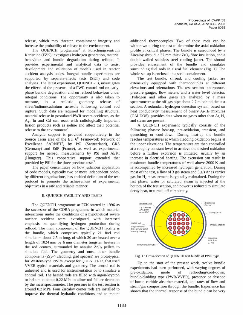
additional thermocouples. Two of these rods can bwithdrawn during the test to determine the axial oxidatioprofile at critical phases. The bundle is surrounded byZircaloy shroud, a 37 mm thick ZrO2 fibre insulation, and a double-walled stainless steel cooling jacket. The shroprovides encasement of the bundle and simulatsurrounding fuel rods in a real fuel element (Fig. 1). Thwhole set-up is enclosed in a steel containment.
The test bundle, shroud, and cooling jacket aextensively equipped with thermocouples at differenelevations and orientations. The test section incorporapressure gauges, flow meters, and a water level detecHydrogen and other gases are analyzed by a mspectrometer at the off-gas pipe about 2.7 m behind the section. A redundant hydrogen detection system, basedheat conductivity measurement of binary Ar-H2 mixtures (CALDOS), provides data when no gases other than Ar, 2 and steam are present.
A QUENCH experiment typically consists of thefollowing phases: heat-up, pre-oxidation, transient, anquenching or cool-down. During heat-up the bundreaches temperatures at which cladding oxidation beginsthe upper elevations. The temperatures are then controat a roughly constant level to achieve the desired oxidatibefore a further excursion is initiated, usually by aincrease in electrical heating. The excursion can resultmaximum bundle temperatures of well above 2000 K anis accompanied by increased hydrogen generation. Durmost of the test, a flow of 3 g/s steam and 3 g/s Ar as cargas for H2 measurement is typically maintained. During thlast phase, water or saturated steam is injected at bottom of the test section, and power is reduced to simuldecay heat, or turned off completely.
unheated rod
Zry claddingZrO pelletcentral TC
2
insulationZrO fiber37 mm
2
Zircaloy rod 6 mm
instrumentation tube
shroud, Zircaloy
cooling jacket
Fig. 1 : Cross-section of QUENCH test bundle of PWR type.
Up to the start of the present work, twelve bundexperiments had been performed, with varying degreespre-oxidation, mode of reflooding/cool-down,bundle/cladding type (PWR/VVER), presence or absenof boron carbide absorber material, and rates of flow asteam/gas composition through the bundle. Experience shown that the thermal response of the bundle can be v
Proceedings of ICAPP ‘08 Anaheim, CA USA, June 8-12, 2008
Paper 8065
f thm
na
d angle
orm
e
S,06veuo
3 g/earoe eore1
ras ofete
ble
trooronrin, tinianres
. Aod
an
s
he nd s
in ge st . re all
d ts, lts. of , 2 d
the the ed the n or
el e nd e ,
difficult to control, particularly during transition phases othe tests such from heat-up to pre-oxidation and reflooding/cool-down. Indeed, the challenges arise frothe very reason that the tests are needed, namelyeliminate limitations in current knowledge of phenomethat pose safety concerns to nuclear plants.
In QUENCH-13, the single unheated fuel rosimulator in the centre of the normal 21-rod bundle wreplaced by the PWR control rod. On-line particle countiequipment was installed in the offgas pipe to enabmeasurement of aerosol flow rates, while the provisionimpactors enables data on the physical and chemical foof the aerosols to be obtained.
III. PRE-TEST CALCULATIONAL SUPPORT
III.A. Planning of test conduct Definition of the experiment involved intensive
discussion within a specialist technical circle within thSource Term area of SARNET, involving FZK, EdF, GRIRSN and PSI. It was decided to use the QUENCH-sequence as the basis for the test conduct; this involpre-conditioning the bundle at about 1473 K for abo4600 s to build up a maximum oxide layer thickness about 210 µm, before ramping the bundle to about 197and reflooding with room temperature water at about 40 to terminate the test. In the present case, the plattemperature was reduced to precondition the control prior to the final thermal transient within which its failurwould occur and the absorber material would be releasThis procedure helped to optimize the conditions fmeasurement of the control rod aerosols releasExperience from bundle experiments, e.g. Phebus FPTsummarised for example in an earlier review7, indicates a rapid release of Cd following control rod rupture, of sevetens of percent of the initial inventory in a few second‘burst release’, followed by release at much lower ratesthe In and Ag components, e.g. a few percent over a thousand seconds. The aerosol measurement straneeded to cope with these very different conditions.
The planning analysis focussed on defining a suitatemperature during the pre-conditioning phase, a powramp rate to provide an adequate time window after conrod failure during which to measure the aerosol transpand a reflood initiation temperature to avoid an oxidatiexcursion and hence prevent damage to the bundle duquench. Off-gas pipe conditions were also investigatedensure temperatures would remain within the operatenvelope of the aerosol measurement system. Varstudies were performed to evaluate the effect of differereflood criteria taking into account timing and temperatuuncertainties, different Zircaloy/steam oxidation kineticand uncertainties in the control rod failure temperaturecontingency action was identified in case the control r
1184
e to
s
f s
d
t f K s u
d
d.
d. as
l , f w gy
e r l
t, g
o g nt t
failure was not apparent until a higher temperature thexpected.
The determination of the QUENCH-13 protocol wabased on numerous calculations with SCDAP/RELAP58, SCDAPSIM9, ATHLET-CD and MAAP4, performed by PSI (SCDAP-based codes), GRS and EdF respectively. TSCDAP-based codes have been extensively asuccessfully used for defining the protocol of previouQUENCH tests, while ATHLET-CD and MAAP could estimate the control rod aerosol release rates, valuablethe test planning. The combined approach took advantaof the relative strengths of the codes. The final pre-tecalculations were performed by PSI with SCDAP/RELAP5The calculations performed by each organization asummarised in the following three sub-sections; an oversummary is given after.
III.B. PSI calculations
The PSI models for QUENCH-13 were develope
from those used in analyses of previous QUENCH teswhich had been benchmarked against experimental resuThe models use 16 SCDAP axial nodes for the bundle, which 10 represent the middle tungsten heated sectioneach for the neighbouring molybdenum conductors, anone each for the top and bottom copper electrodes. In radial direction, separate SCDAP components represent control rod, the inner heated ring of 8 rods, the outer heatring of 12 rods, the 4 unheated corner rods, the shroud, outer cooling jacket and the containment respectively. Aexample of the agreement obtained is shown in Fig. 2, fthe steam pre-oxidation phase of PWR test QUENCH-1010.
Fig. 2 : SCDAPSIM calculation of QUENCH-10 centre rod temperature evolution
A feature of the SCDAP codes is a mechanistic modfor control rod failure, based on a kinetic treatment of theutectic interaction between the stainless steel cladding aZircaloy control rod guide tube, and on the Fe-Zr phasdiagram. As part of preliminary studies for QUENCH-13
Proceedings of ICAPP ‘08 Anaheim, CA USA, June 8-12, 2008
Paper 8065
thate
there
l tethoisiivthdha
it
gauA
30neodfueesA io
tho
e K of nd rol
ate e
ed,
st
nce K on l re to m he s -s ata
en ay e e ce
of f
at t /s g
the implementation of this model was checked and kinetic part found to be faulty, giving predicted failure too low a temperature. The SCDAP codes used here wcorrected using data from the original report11 on which the model was based.
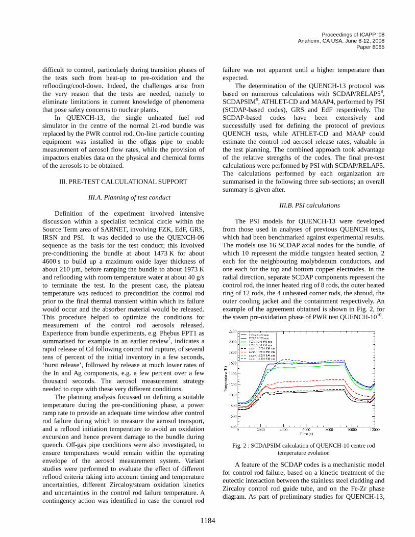
In the present work, particular attention was paid to model of the offgas pipe, for which 30 nodes were usReliable simulations of the pipe wall and gas temperatuwere needed to assist in the planning of the installationthe on-line aerosol measuring equipment. The modethis part of the facility was therefore improved taking betaccount of thermal capacities and heat transfer in region of the facility, and benchmarked against results frQUENCH-1212 for both bundle and offgas line, since thexperiment had a similar offgas pipe configuration. Thtest also involved a power ramp and hold, this time to ga maximum bundle temperature of about 1473 K in hold period, followed by a further ramp and reflooTypical results for the offgas line are shown in Fig. 3. Tmodel could therefore be used to predict temperature fluid conditions where instrumentation was lacking.
Fig. 3 : Comparison of QUENCH-12 offgas pipe temperatures wSCDAPSIM calculation
First, attention was paid to the pre-conditionintemperature. Initial calculations aimed at platetemperatures of 1250 K and 1350 K, seeing that SCDpredicted control rod failure temperatures of about 141450 K for typical QUENCH test conditions. It was thedecided by the calculational partnership to adopt a vconservative approach, avoiding any possibility of rfailure before the final ramp (which would prevent useaerosol data from being obtained) by keeping the plattemperature down to 1250 K, i.e. at the minimum stainlsteel liquefaction temperature as defined in the SCDstainless steel / Zircaloy dissolution model on the basisthe Fe/Zr phase diagram, and all subsequent calculatwere performed with this condition.
The next step was to define the power ramp rate would lead to a long enough period for aeros
1185
e re
e d. s
of of r is m s e e . e nd
h
P - ry
l au s P of ns
at l
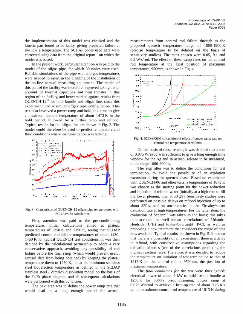
measurements from control rod failure through to thproposed quench temperature range of 1800-1900(precise temperature to be defined on the basis sensitivity studies). The rates chosen were 0.05, 0.1 a0.2 W/s/rod. The effect of these ramp rates on the controd temperature at the axial position of maximumtemperature, 950mm, is shown in Fig. 4.
Fig. 4: SCDAPSIM calculation of effect of power ramp rate on control rod temperature at 950mm
On the basis of these results, it was decided that a rof 0.075 W/s/rod was sufficient to give a long enough timwindow for the Ag and In aerosol release to be measurin the range 1000-2000 s.
The step after was to define the conditions for tetermination, to avoid the possibility of an oxidationexcursion during the quench phase. Based on experiewith QUENCH-06 and other tests, a temperature of 1873was chosen as the starting point for the power reductiand injection of reflood water (initially at a high rate to filthe lower plenum, then at 50 g/s). Sensitivity studies weperformed on possible delays on reflood injection of up about 350 s, and on uncertainties in the Zircaloy/steaoxidation rate at high temperatures. For the latter item, tevaluation of Schanz13 was taken as the basis; this takeinto account the well-known correlations of UrbanicHeidrick (U/H) and Prater-Courtright (P/C), as well aproposing a new treatment that considers the range of dnow available. Typical results are shown in Fig. 5. It is sethat there is a possibility of an excursion if there is a delin reflood, with conservative assumptions regarding thoxidation kinetics (use of the correlations predicting thhighest reaction rate). Therefore, it was decided to reduthe temperature on initiation of test termination to that 1813 K on the control rod at 950 mm, the position omaximum temperature.
The final conditions for the test were thus agreed: electrical power of about 9 kW to stabilise the bundle 1250 K for 5000 s preconditioning, power ramp a0.075 W/s/rod to achieve a heat-up rate of about 0.25 Kup to a maximum control rod temperature of 1813 K durin
Proceedings of ICAPP ‘08 Anaheim, CA USA, June 8-12, 2008
Paper 8065
toamarana
by
isin in
e cs00teed, de
tic ue
ed
n
n
re te-
e d
if . e
ng s s
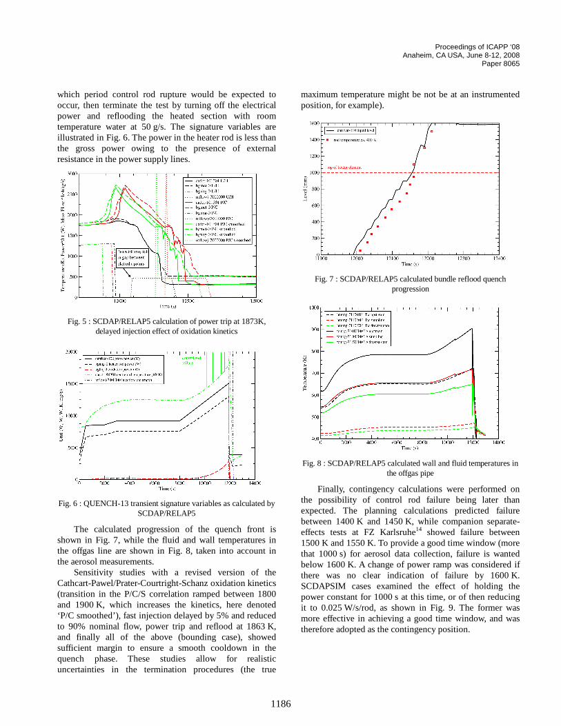
which period control rod rupture would be expected occur, then terminate the test by turning off the electricpower and reflooding the heated section with rootemperature water at 50 g/s. The signature variables illustrated in Fig. 6. The power in the heater rod is less ththe gross power owing to the presence of externresistance in the power supply lines.
Fig. 5 : SCDAP/RELAP5 calculation of power trip at 1873K, delayed injection effect of oxidation kinetics
Fig. 6 : QUENCH-13 transient signature variables as calculatedSCDAP/RELAP5
The calculated progression of the quench front shown in Fig. 7, while the fluid and wall temperatures the offgas line are shown in Fig. 8, taken into accountthe aerosol measurements.
Sensitivity studies with a revised version of thCathcart-Pawel/Prater-Courtright-Schanz oxidation kineti(transition in the P/C/S correlation ramped between 18and 1900 K, which increases the kinetics, here deno‘P/C smoothed’), fast injection delayed by 5% and reducto 90% nominal flow, power trip and reflood at 1863 Kand finally all of the above (bounding case), showesufficient margin to ensure a smooth cooldown in thquench phase. These studies allow for realisuncertainties in the termination procedures (the tr
1186
l e
l
d
maximum temperature might be not be at an instrumentposition, for example).
Fig. 7 : SCDAP/RELAP5 calculated bundle reflood quench progression
Fig. 8 : SCDAP/RELAP5 calculated wall and fluid temperatures ithe offgas pipe
Finally, contingency calculations were performed othe possibility of control rod failure being later thanexpected. The planning calculations predicted failubetween 1400 K and 1450 K, while companion separaeffects tests at FZ Karlsruhe14 showed failure between 1500 K and 1550 K. To provide a good time window (morthat 1000 s) for aerosol data collection, failure is wantebelow 1600 K. A change of power ramp was consideredthere was no clear indication of failure by 1600 KSCDAPSIM cases examined the effect of holding thpower constant for 1000 s at this time, or of then reduciit to 0.025 W/s/rod, as shown in Fig. 9. The former wamore effective in achieving a good time window, and watherefore adopted as the contingency position.
Proceedings of ICAPP ‘08 Anaheim, CA USA, June 8-12, 2008
Paper 8065
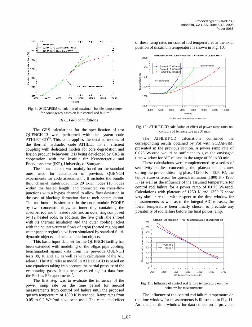
Fig. 9 : SCDAPSIM calculation of maximum bundle temperature for contingency cases on late control rod failure
III.C. GRS calculations
The GRS calculations for the specification of test QUENCH-13 were performed with the system code ATHLET-CD15. This code applies the detailed models of the thermal hydraulic code ATHLET in an efficient coupling with dedicated models for core degradation and fission product behaviour. It is being developed by GRS in cooperation with the Institut für Kernenergetik und Energiesysteme (IKE), University of Stuttgart.
The input data set was mainly based on the standard ones used for calculation of previous QUENCH experiments for code assessment16. It includes the bundle fluid channel, subdivided into 20 axial nodes (10 nodes within the heated length) and connected via cross-flow junctions with a bypass channel to allow flow deviation in the case of blockage formation due to melt accumulation. The rod bundle is simulated in the code module ECORE by two concentric rings, an inner ring containing the absorber rod and 8 heated rods, and an outer ring composed by 12 heated rods. In addition, the five grids, the shroud with its thermal insulation and the outer cooling jacket with the counter-current flows of argon (heated region) and water (upper region) have been simulated by standard fluid-dynamic objects and heat conduction objects.
This basic input data set for the QUENCH facility has been extended with modelling of the offgas pipe cooling, benchmarked against data from the previous QUENCH tests 08, 10 and 11, as well as with calculation of the AIC release. The AIC release model in ATHLET-CD is based on rate equations taking into account the partial pressure of the evaporating gases. It has been assessed against data from the Phebus FP experiments17.
The first step was to evaluate the influence of the power ramp rate on the time period for aerosol measurements from control rod failure until the proposed quench temperature of 1800 K is reached. Ramp rates from 0.05 to 0.2 W/s/rod have been used. The calculated effect
1187
of these ramp rates on control rod temperatures at the axial position of maximum temperature is shown in Fig. 10.
Fig. 10 : ATHLET-CD calculation of effect of power ramp rates on control rod temperature at 950 mm
The ATHLET-CD calculations confirmed the corresponding results obtained by PSI with SCDAPSIM, presented in the previous section. A power ramp rate of 0.075 W/s/rod would be sufficient to give the envisaged time window for AIC release in the range of 20 to 30 min.
These calculations were complemented by a series of sensitivity studies concerning the plateau temperatures during the pre-conditioning phase (1250 K - 1350 K), the temperature criterion for quench initiation (1800 K - 1900 K) as well as the influence of the assumed temperature for control rod failure for a power ramp of 0.075 W/s/rod. Calculations with plateaus of 1250 K and 1350 K show very similar results with respect to the time window for measurements as well as to the integral AIC releases, the lower temperature been finally chosen to preclude any possibility of rod failure before the final power ramp.
ATHLET−CD Mod 2.1A − Pre−Test Calculation of QUENCH−13
1400 1450 1500 1550 1600 1650 1700
CR Failure Temperature (K)
0
200
400
600
800
1000
1200
1400
1600
1800
Tim
e w
indo
w fo
r m
easu
rem
ents
(s)
T=1250 KT=1350 K
Fig. 11 : Influence of control rod failure temperature on time window for measurements
The influence of the control rod failure temperature on the time window for measurements is illustrated in Fig. 11. An adequate time window for data collection is provided
ATHLET−CD Mod 2.1A − Pre−Test Calculation of QUENCH−13
Guide tube temperature at 950 mm
4000 5000 6000 7000 8000 9000 10000 11000
Time (s)
1000
1200
1400
1600
1800
2000
Tem
pera
ture
(K
)
Ramp 0.20 W/s/rodRamp 0.10 W/s/rodRamp 0.05 W/s/rod
quench criterion
CR failure temp.
Proceedings of ICAPP ‘08 Anaheim, CA USA, June 8-12, 2008
Paper 8065
thees
ll forse
ionsteerreonion
ns theresto s
on b it oth
he d ie og
g la
th
r to ile
:
e
for temperatures below 1550 K, the upper bound of failure temperatures observed in the separate-effect tperformed at FZ Karlsruhe14.
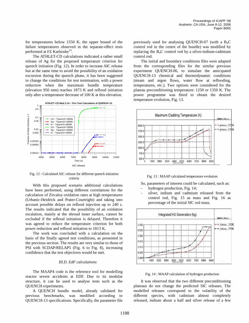
The ATHLET-CD calculations indicated a rather smarelease of Ag for the proposed temperature criterion quench initiation (Fig. 12). In order to increase AIC releabut at the same time to avoid the possibility of an oxidatexcursion during the quench phase, it has been suggeto change the conditions for test termination, with a powreduction when the maximum bundle temperatu(elevation 950 mm) reaches 1873 K and reflood initiationly after a temperature decrease of 100 K at this elevat
Fig. 12 : Calculated AIC release for different quench initiation criteria
With this proposed scenario additional calculatiohave been performed, using different correlations for calculation of Zircaloy oxidation rates at high temperatu(Urbanic-Heidrick and Prater-Courtright) and taking inaccount possible delays on reflood injection up to 240The results indicated that the possibility of an oxidatiescalation, mainly at the shroud inner surface, cannotexcluded if the reflood initiation is delayed. Thereforewas agreed to reduce the temperature criterion for bpower reduction and reflood initiation to 1813 K.
The work was concluded with a calculation on tbasis of the finally agreed test conditions, as presentethe previous section. The results are very similar to thosPSI with SCDAP/RELAP5 (Fig. 6 to Fig. 8), increasinconfidence that the test objectives would be met.
III.D. EdF calculations
The MAAP4 code is the reference tool for modellin
reactor severe accidents at EDF. Due to its modustructure, it can be used to analyse tests such asQUENCH experiments.
A QUENCH bundle model, already validated foprevious benchmarks, was modified according QUENCH-13 specifications. Specifically, the parameter f
ATHLET−CD Mod 2.1A − Pre−Test Calculation of QUENCH−13
AIC release
4000 5000 6000 7000 8000 9000 10000 11000
Time (s)
0.00010
0.00050
0.00100
0.005
0.01
0.05
0.1
0.5
1
Fra
ctio
n of
initi
al in
vent
ory
(−)
Cd − Tquench=1800KAg − Tquench=1800KIn − Tquench=1800KCd − Tquench=1900KAg − Tquench=1900KIn − Tquench=1900K
1188
ts
d
.
.
e
n f
r e
previously used for analysing QUENCH-07 (with a B4C control rod in the centre of the bundle) was modified by replacing the B4C control rod by a silver-indium-cadmium control rod.
The initial and boundary conditions files were adaptedfrom the corresponding files for the similar previous experiment QUENCH-06, to simulate the anticipated QUENCH-13 chemical and thermodynamic conditions (steam and argon flows, water flow at reflooding, temperatures, etc.). Two options were considered for theplateau preconditioning temperature: 1250 or 1350 K. Thepower programme was fitted to obtain the desiredtemperature evolution, Fig. 13.
Fig. 13 : MAAP calculated temperature evolution
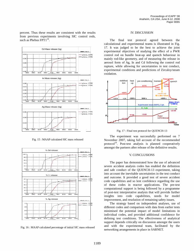
So, parameters of interest could be calculated, such as- hydrogen production, Fig. 14; - silver, indium and cadmium released from the
control rod, Fig. 15 as mass and Fig. 16 as percentage of the initial SIC rod mass.
Fig. 14 : MAAP calculation of hydrogen production
It was observed that the two different preconditioning plateaus do not change the predicted SIC releases. Thmodelled releases correspond to the volatility of thedifferent species, with cadmium almost completely released, indium about a half and silver release of a few
Proceedings of ICAPP ‘08 Anaheim, CA USA, June 8-12, 2008
Paper 8065
us,
ed
. t
in in ,
7 d y .
ed ion g ct nt se st e r l
of ts r l rs
percent. Thus these results are consistent with the resfrom previous experiments involving SIC control rodsuch as Phebus FPT118.
Fig. 15 : MAAP calculated SIC mass released
Fig. 16 : MAAP calculated percentage of initial SIC mass releas
1189
lts
IV. DISCUSSION The final test protocol agreed between the
calculational and experimental teams is illustrated in Fig17. It was judged to be the best to achieve the joinexperimental objectives of studying the effect of a PWRcontrol rod on bundle heat-up and quench behaviour mainly rod-like geometry, and of measuring the release aerosol form of Ag, In and Cd following the control rodrupture, while allowing for uncertainties in test conductexperimental conditions and predictions of Zircaloy/steamoxidation.
corner rod 60 s after failure
~1.5 h ~1 h
~600°C
5000 s ~3000 s
Ar, 3 g/s
Superheated steam (530°C), 3 g/s
Tmax=1540°C
Water, 50 g/s(~250 s)
~4.5 kW
~9 kW
0 kW
T
Pel
m .
~8 kW
977°C
~16 kW
~4000 s
stabilisa-tion
heat-up
pre-conditioning transient quench
Trate= 0.1 K/s
Prate= 0.075 W/s/rod
Trate= 0.2 K/s
Time
Fig. 17 : Final test protocol for QUENCH-13
The experiment was successfully performed on November 2007, taking full account of the recommendeprotocol19. Post-test analysis is planned cooperativelamongst the partners after release of the definitive results
V. CONCLUSIONS
The paper has demonstrated how the use of advanc
severe accident analysis codes has enabled the definitand safe conduct of the QUENCH-13 experiment, takininto account the inevitable uncertainties in the test conduand outcome. It provided a good test of severe accidecode capabilities and so lent confidence regarding the uof these codes in reactor applications. The pre-tecomputational support is being followed by a programmof post-test interpretative analysis that will provide furtheinsights into code capabilities, needs for modeimprovement, and resolution of remaining safety issues.
The strategy based on independent analyses, usedifferent codes and comparison with data from earlier tesminimised the potential impact of model limitations inindividual codes, and provided additional confidence fodefining test conditions. The effectiveness of analyticasupport depends critically on discussion amongst the useand with the experimental team, facilitated by thenetworking arrangements in place in SARNET.
Proceedings of ICAPP ‘08 Anaheim, CA USA, June 8-12, 2008
Paper 8065
n
n
-
fo
,
. e
rm r
,
l ,
rt
)
Several of the questions to be answered in the presecontext are analogous to those arising in reactor analysefor example in the definition of criteria for water injection as an accident management measure. The experienceperforming analytical support for experiments of this kindprovides a spin-off benefit to reactor application, helping tomake the most effective use of the available tools iaddressing plant safety issues.
ACKNOWLEDGMENTS The SARNET Network of Excellence is partly
financed by the European Commission through FP6EURATOM Contract FI6O-CT-2004-509065. The FZK work is sponsored by the HGF Programme NUKLEAR.The development and validation of the code ATHLET-CDare sponsored by the German Federal Ministry oEconomics and Technology (BMWi). The PSI authors alsthank Swissnuclear for significant financial support toconduct these research activities.
NOMENCLATURE
EdF Electricité de France EU European Union FZK Forschungszentrum Karlsruhe GRS Gesellschaft für Anlagen und
Reaktorsicherheit IKE Institut für Kernenergetik und
Energiesysteme P/C Prater/Courtright PSI Paul Scherrer Institute PWR Pressurised Water Reactor SET Separate-Effects Tests SIC Silver/Indium/Cadmium U/H Urbanic/Heidrick VVER Vodo-Vodyanoi Energetichesky Reactor
(PWR of Russian type)
REFERENCES 1. Committee on the Safety of Nuclear Installations
“Progress Made in the Last Fifteen Years throughAnalyses of the TMI-2 Accident Performed in MemberCountries”, OECD/NEA/CSNI/R(2005)1 (2005).
2. T. HASTE et al., “Degraded Core Quench: A StatusReport - November 1995”, NEA/CSNI/R(96)14, OCDE/GD(97)5 (1996).
3. L. SEPOLD, W. Hering, G. Schanz, W. Scholtyssek, MSteinbrück and J. Stuckert, “Severe Fuel DamagExperiments performed in the QUENCH Facility with 21-rod Bundles of LWR-Type”, Nucl. Eng. Des. 237, 2157-2164 (2007).
4. T. HASTE, P. Giordano, L. Herranz and J.-C.-Micaelli, “SARNET: Integrating Severe Accident
1190
t s,
of
Research in Europe – Safety Issues in the Source TeArea”, Proc. Int. Conf. on Advances in Nuclear PowePlants (ICAPP’06), Reno, USA (2006).
5. J. BIRCHLEY, T. Haste, W. Hering and Ch. Homann“Pre-Test Analytical Support for ExperimentsQUENCH-10, -11 and -12”, Proc. Int. Conf. on Nucl. Energy in New Europe, Portorož, Slovenia (2006).
6. L. SEPOLD et al., “Experimental and ComputationaResults of the QUENCH-06 Test (OECD ISP-45)”FZKA 6664 (2004).
7. T. HASTE and W. Plumecocq, “Control Rod andStructural Material Release Modelling in ELSA2”, 9th Int. QUENCH Workshop, FZ Karlsruhe, Germany (2003).
8. L. SIEFKEN et al., “SCDAP/RELAP5/MOD3.2 Code Manual”, NUREG/CR-6150 Rev. 1 (1997).
9. Innovative Systems Software, “RELAP5/SCDAPSIM/MOD3.4 Code Manual” (2003).
10. G. SCHANZ et al., “Results of the QUENCH-10Experiment on Air Ingress”, FZKA 7087 (2006).
11. P. HOFMANN and M. Markiewicz, “Chemical Behaviour of (Ag,In,Cd) Absorber Rods in SevereLWR Accidents”, KfK 4670 (1990).
12. J. STUCKERT et al., “Results of the QUENCH-12Experiment with a Russian VVER-type Bundle”,FZKA 7307 (2008).
13. G. SCHANZ, B. Adroguer and A. Volchek, “AdvancedTreatment of Zircaloy Cladding High-TemperatureOxidation in Severe Accident Code Calculations – Pa1: Experimental Database and Basic Modelling”, Nucl. Eng. Des. 232, 75-84 (2004).
14. M. STEINBRÜCK et al., “Single Rod Experiments onFailure of SIC Control Rods”, 13th Int. QUENCH Workshop, FZ Karlsruhe, Germany (2007).
15. V. TESCHENDORFF and K. Trambauer, “Simulationof Severe Accidents with Detailed Thermal-HydraulicModels”, Kerntechnik, 63, 18-24 (1998).
16. H. AUSTREGESILO et al., “Post-Test Calculation andUncertainty Analysis of the Experiment QUENCH-07with the System Code ATHLET-CD”, Proc. 11th International Topical Meeting on Nuclear ReactorThermal-Hydraulics (NURETH-11), Avignon, France (2005).
17. K. TRAMBAUER et al., “Weiterentwicklung des Rechenprogrammsystems ATHLET / ATHLET-CD”,Gesellschaft für Anlagen- und Reaktorsicherheit (GRSmbH, GRS-A-3215 (2004).
18. D. JACQUEMAIN et al., “FPT1 Final Report”, IRSN report IP/00/479 (2000).
19. J. STUCKERT et al., “First Results of the QUENCH-13 Bundle Experiment with a Silver-Indium-CadmiumControl Rod”, 13th Int. QUENCH Workshop, FZ Karlsruhe, Germany (2007).

![MuCool Superconducting Solenoid Quench …...Index Terms— Superconducting solenoid, Magnetic field, Quench, 3D simulations, Test Stand. I. INTRODUCTION HE MUCOOL experiment [1] magnet](https://img.pdfslide.us/doc/110x75/5e92b2bd1d72c02008514bd1/mucool-superconducting-solenoid-quench-index-termsa-superconducting-solenoid.jpg)