Embed Size (px)
Citation preview
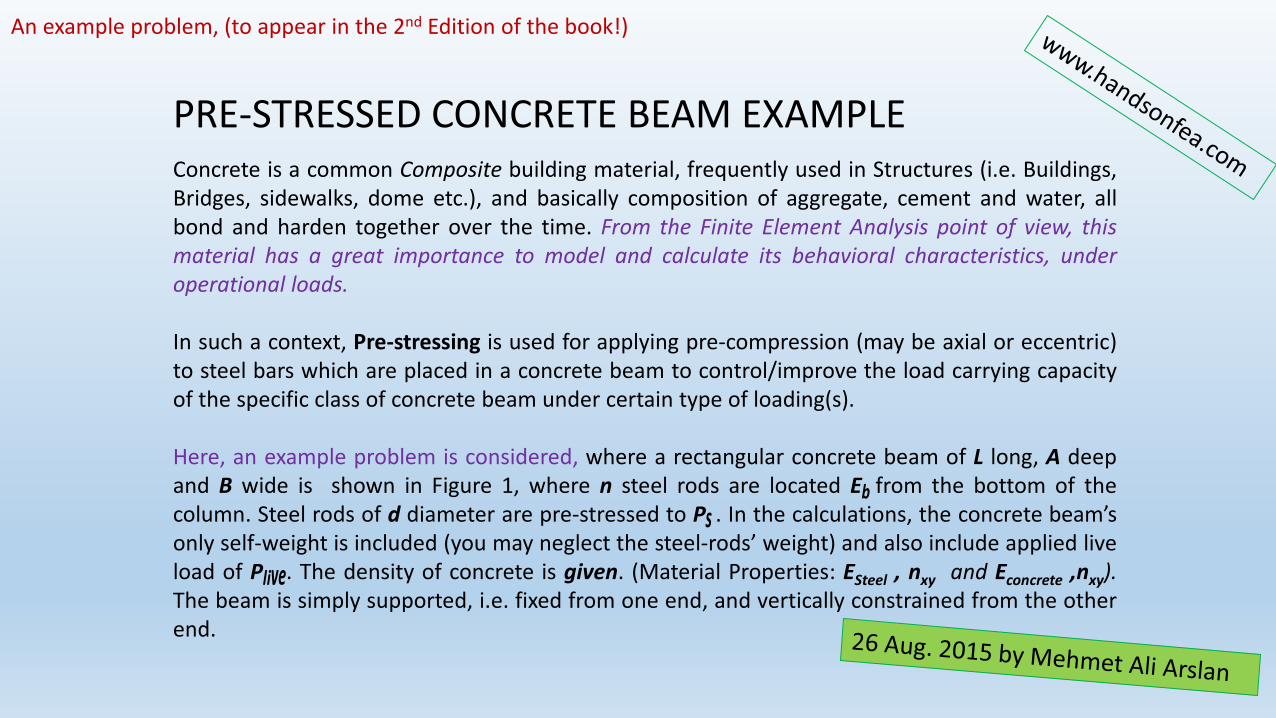
PRE-STRESSED CONCRETE BEAM EXAMPLEConcrete is a common Composite building material, frequently used in Structures (i.e. Buildings,Bridges, sidewalks, dome etc.), and basically composition of aggregate, cement and water, allbond and harden together over the time. From the Finite Element Analysis point of view, thismaterial has a great importance to model and calculate its behavioral characteristics, underoperational loads.
In such a context, Pre-stressing is used for applying pre-compression (may be axial or eccentric)to steel bars which are placed in a concrete beam to control/improve the load carrying capacityof the specific class of concrete beam under certain type of loading(s).
Here, an example problem is considered, where a rectangular concrete beam of L long, A deepand B wide is shown in Figure 1, where n steel rods are located E from the bottom of thecolumn. Steel rods of d diameter are pre-stressed to P . In the calculations, the concrete beam’sonly self-weight is included (you may neglect the steel-rods’ weight) and also include applied liveload of P . The density of concrete is given. (Material Properties: ESteel , nxy and Econcrete ,nxy).The beam is simply supported, i.e. fixed from one end, and vertically constrained from the otherend.
An example problem, (to appear in the 2nd Edition of the book!)
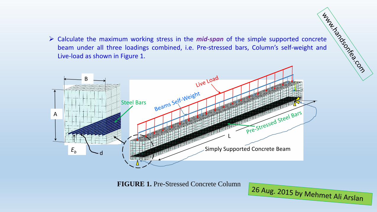
Calculate the maximum working stress in the mid-span of the simple supported concretebeam under all three loadings combined, i.e. Pre-stressed bars, Column’s self-weight andLive-load as shown in Figure 1.
B
d
L
A
Simply Supported Concrete Beam
Steel Bars
Eb
FIGURE 1. Pre-Stressed Concrete Column
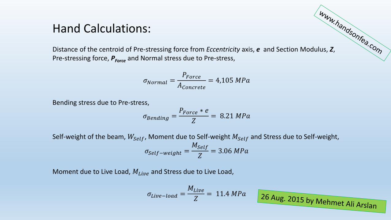
Hand Calculations:
Distance of the centroid of Pre-stressing force from Eccentricity axis, e and Section Modulus, Z, Pre-stressing force, PForce and Normal stress due to Pre-stress,
𝜎𝑁𝑜𝑟𝑚𝑎𝑙 =𝑃𝐹𝑜𝑟𝑐𝑒
𝐴𝐶𝑜𝑛𝑐𝑟𝑒𝑡𝑒= 4,105 𝑀𝑃𝑎
Bending stress due to Pre-stress,
𝜎𝐵𝑒𝑛𝑑𝑖𝑛𝑔 =𝑃𝐹𝑜𝑟𝑐𝑒 ∗ 𝑒
𝑍= 8.21 𝑀𝑃𝑎
Self-weight of the beam, 𝑊𝑆𝑒𝑙𝑓, Moment due to Self-weight 𝑀𝑆𝑒𝑙𝑓 and Stress due to Self-weight,
𝜎𝑆𝑒𝑙𝑓−𝑤𝑒𝑖𝑔ℎ𝑡 =𝑀𝑆𝑒𝑙𝑓
𝑍= 3.06 𝑀𝑃𝑎
Moment due to Live Load, 𝑀𝐿𝑖𝑣𝑒 and Stress due to Live Load,
𝜎𝐿𝑖𝑣𝑒−𝑙𝑜𝑎𝑑 =𝑀𝐿𝑖𝑣𝑒
𝑍= 11.4 𝑀𝑃𝑎
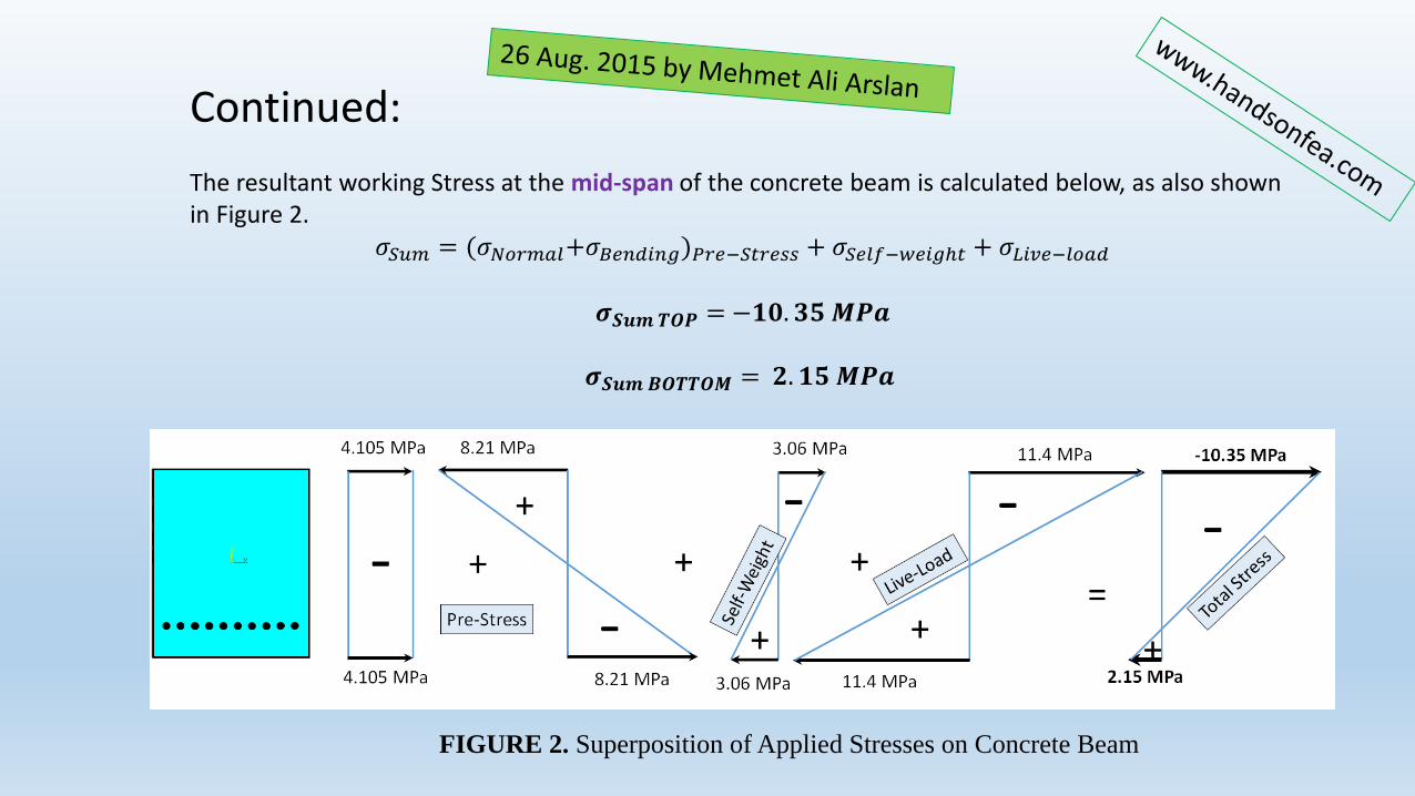
Continued:
The resultant working Stress at the mid-span of the concrete beam is calculated below, as also shown in Figure 2.
𝜎𝑆𝑢𝑚 = (𝜎𝑁𝑜𝑟𝑚𝑎𝑙+𝜎𝐵𝑒𝑛𝑑𝑖𝑛𝑔)𝑃𝑟𝑒−𝑆𝑡𝑟𝑒𝑠𝑠 + 𝜎𝑆𝑒𝑙𝑓−𝑤𝑒𝑖𝑔ℎ𝑡 + 𝜎𝐿𝑖𝑣𝑒−𝑙𝑜𝑎𝑑
𝝈𝑺𝒖𝒎 𝑻𝑶𝑷 = −𝟏𝟎. 𝟑𝟓 𝑴𝑷𝒂
𝝈𝑺𝒖𝒎𝑩𝑶𝑻𝑻𝑶𝑴 = 𝟐. 𝟏𝟓 𝑴𝑷𝒂
FIGURE 2. Superposition of Applied Stresses on Concrete Beam
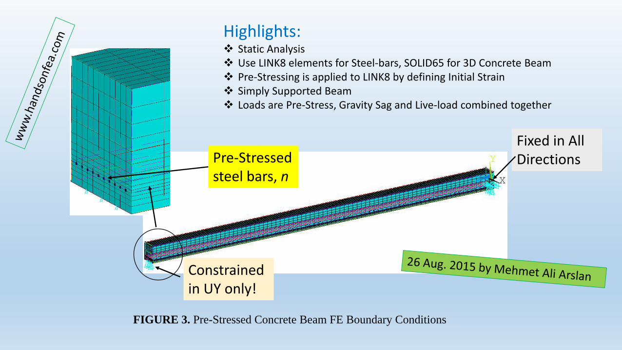
Fixed in AllDirections
Constrainedin UY only!
Pre-Stressedsteel bars, n
FIGURE 3. Pre-Stressed Concrete Beam FE Boundary Conditions
Highlights: Static Analysis Use LINK8 elements for Steel-bars, SOLID65 for 3D Concrete Beam Pre-Stressing is applied to LINK8 by defining Initial Strain Simply Supported Beam Loads are Pre-Stress, Gravity Sag and Live-load combined together
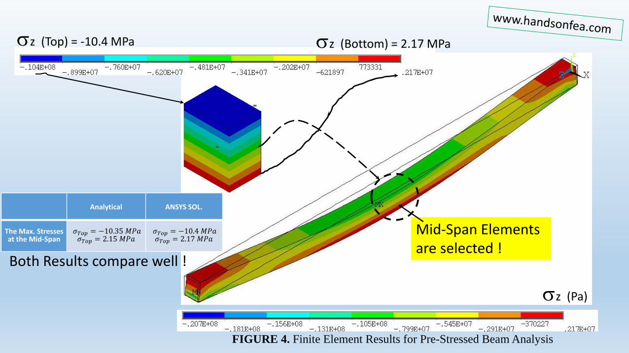
sz (Pa)
Mid-Span Elementsare selected !
sz (Top) = -10.4 MPa sz (Bottom) = 2.17 MPa
Analytical ANSYS SOL.
The Max. Stressesat the Mid-Span
𝜎𝑇𝑜𝑝 = −10.35 𝑀𝑃𝑎𝜎𝑇𝑜𝑝 = 2.15 𝑀𝑃𝑎
𝜎𝑇𝑜𝑝 = −10.4 𝑀𝑃𝑎𝜎𝑇𝑜𝑝 = 2.17 𝑀𝑃𝑎
Both Results compare well !
FIGURE 4. Finite Element Results for Pre-Stressed Beam Analysis