Embed Size (px)
Citation preview

ML513 | v13 28-June-2021
Pre-Start Ventilation System Manual
ML 513
Important Note:It is essential for safety that the installer and user of the Expo system follow these instructions.Please refer to the applicable standards for principles and definition.These instructions apply only to the ventilation system. It is the responsibility of the manufacturer of the machine to provide instructions for the enclosure.


ML513 | v13 i
Section 1: Pre-Start Ventilation System - General Specification ..................................................1Ventilation Control Unit Data ......................................................................................................................................... 2Outlet Valve with Integral Spark Arrestor (contains overpressure Relief Valve). .................................... 3
Section 2: Quick User Guide ...............................................................................................................4Operation of the System .................................................................................................................................................. 4
Section 3: Application Suitability ......................................................................................................5Section 4: Description and Principle of Operation ..........................................................................6
Local Operation..................................................................................................................................................................... 6Remote control operation (Optional) ........................................................................................................................... 7..................................................................................................................................................................................................... 8
Section 5: Main Components ..............................................................................................................8Air Supply Filter .................................................................................................................................................................... 8Ventilation Flow Regulator.............................................................................................................................................. 8Ventilation Control Pilot Operated Regulator.......................................................................................................... 8Logic Air Supply Regulator............................................................................................................................................... 8Visual indicators ................................................................................................................................................................... 9/PA Terminal Box ............................................................................................................................................................... 9/IS Intrinsically Safe (Ex i)................................................................................................................................................. 9/PO Pneumatic Output Signals....................................................................................................................................... 9Outlet Valve ........................................................................................................................................................................... 9
Section 6: Installation of the System ............................................................................................ 10Air Supply Quality ............................................................................................................................................................. 10Pipe Work ............................................................................................................................................................................. 11Multiple Enclosures .......................................................................................................................................................... 11Power Supplies and their Isolation............................................................................................................................ 11
Section 7: Commissioning ............................................................................................................... 11Commissioning the System .......................................................................................................................................... 11Procedure for increasing air flow............................................................................................................................... 12
Section 8: Maintenance of the System .......................................................................................... 14General maintenance ...................................................................................................................................................... 14Maintenance of Electronic Timer................................................................................................................................ 14
Section 9: Fault Finding ................................................................................................................... 15General Information......................................................................................................................................................... 15Pre-Start Ventilation System has sufficient flow but no “System Ventilating” signal. ....................... 15Ventilation does not start or fails to complete .................................................................................................... 16Ventilation Time Insufficient....................................................................................................................................... 16Flow Sensor Calibration.................................................................................................................................................. 17
Section 10: Recommended Spares List ......................................................................................... 17Section 11: Glossary ........................................................................................................................ 17Section 12: Drawings and Diagrams .............................................................................................. 18Section 13: Certification .................................................................................................................. 18

Section 1: Pre-Start Ventilation System - General Specification
PV Sizes - Capacity Tolerance3PV 500 to 1500 NI/min -0 +20%5PV 2000 to 6000 NI/min -0 +20%7PV 7000 to 14000 NI/min -0 +20%
Construction Materialss 316 Stainless Steel
Timing MethodET Electronic Timer
ES Electronic Timer with EPPS
Output Signals
ISSwitch contacts in Exe Junction Box for IS circuit connection.
PASwitch contacts in Exe Junction Box for non-IS connection.
PO Pneumatic Output signals
Options Codes (Added if applicable)CV Continuous Ventilation
HSHigh Supply Pressure Up to 16 barg (Size 5 & Size 7 only)
OV Pneumatically Oper-ated Outlet Valve
HP High Pressure
Starting ModeLS Local Start Via internal Push ButtonRS Remote Start Via internal EX rated solenoid valve
24 VDC 115 VAC 230 VAC24 VDC (IS)
RS options include a local start
Air Inlet ConnectionAir Supply Air Outlet to Motor
3PV 5PV 7PV 3PV 5PV 7PVN = NPT (F) 3/4” 1” 2” 3/4” 1” 2”A = ANSI 1” 1” N/A 1” 1” N/AG = BSPP 3/4” 1” 2” 3/4” 1” 2”D = DIN DN 20 DN 25 N/A DN 20 DN 25 N/A
Reference points and signals: 1/8” NPT(F)
Hazardous Area Classification
FOR ALL OPTIONS COVERED IN THIS MANUAL, (Except Pneumatic Output /PO and LT options)
ExVeritas 20ATEX0717XEN 60079-0, EN 60079-7<ex> ll 2 G Ex e ia IIC T5 Gb Tamb -20°C to +59°Cor ll 2 G Ex e ia IIC T4 Gb Tamb -20°C to +60°Cor ll 2 G Ex db e ia IIC T3 or T4* Gb Tamb -60°C to +60°C * dependent on heater used.
IECEx EXV 20.0050EN 60079-0, EN 60079-7 Ex e ia IIC T5 Gb Tamb -20°C to +59°Cor Ex e ia IIC T4 Gb Tamb -20°C to +60°Cor Ex db e ia IIC T3 or T4* Gb Tamb -60°C to +60°C * dependent on heater used.
FOR ALL OPTIONS (Including Pneumatic Output /PO)
EUROPE – EXPO 13MDOC1314Suitable for use with Ex e & Ex n electrical rotating machines
IECEx – EXPO 13MDOC1313Suitable for use with Ex E & Ex n electrical rotating machines
#PV ss LS N ET PA Other OptionsModel Number:
Page1
ML513 | v13Expo Technologies UK
T: +44 (0) 20 8398 8011E: [email protected]
Expo Technologies UST: +1 (440) 247 5314
Expo Technologies ChinaT: +86 532 8906 9858

SPECIAL CONDITIONS FOR SAFE USE / CONDITIONS OF CERTIFICATE
(applicable to the options covered by this manual – Do not include Low temperature option).
•This system is intended for use as a Pre-Start Ventilation system, to be used with motors separately approved (by others). It is not a purge & pressurization system for hazardous area motors.
•When the apparatus incorporates a remote start function via an intrinsically-safe solenoid, the installer and user must ensure that the I.S. parameters of the associated apparatus and wiring (by others) meet the certification parameters of that solenoid valve.
Ventilation Control Unit Data
Ventilated Machine Enclosure: Ex e, Ex n Rotating Electrical Machines.
Enclosure Test Pressure: Maximum working = Outlet Valve opening pressure x 1.5.
Ventilation Time: User selectable up to 99 minutes (Tolerance: -0 + 3s).
Ventilation Initiation: Local Switch (LS): Internal Push Button Operator.
Remote Start (RS) Optional:
Internal EX-rated solenoid valve: 24V DC,110V AC or 230V AC.
Indicators: Black / Flashing Yellow :
Stand By / System Ventilating.
Red / Green : Not Ventilated / Ventilation Complete.
Pneumatic Signals: System Ventilating 4.0 barg (60 psig) 1/8” NPT (F), plug fitted.
Ventilation Complete: 4.0 barg (60 psig) 1/8” NPT (F), plug fitted.
System Ventilating & VentilationComplete Contacts:
SPCO electrical switch, certified Ex db IIC T6,Contact ratings 250 Vac 4 Amps, AC15.
Temperature Limits: -20ºC to +60ºC (T4). -20ºC to +59ºC (T5).
Ventilation Flow Sensors: Factory set to match ventilation flow rate required.
Supply Pressure: 4 to 10 barg (60 to 145 psig).
High Supply Pressure (Optional): 4 - 16 barg (60 - 232 psig) for 5PV and 7PV system.
Compressed Air Supply: Clean, Dry Oil Free Air or inert Gas. Refer to Air Supply Quality sectionin Installation of the System.
Logic Regulator & Gauge: Factory set to 4 barg (60 psig).
Air Consumption: <10Nl/min when not in Ventilation mode.
Mounting Method Wall mounting straps & spacers. Fix holes as per drawing.
/PA Terminal Box: Stainless Steel, Ex e IIC T5 Gb / Ex tb IIIC T100ºC Db IP66 Tamb : -20ºCto +55ºC with Ex e terminals, front access cover & lower removablegland plate. Stainless Steel, Ex e IIC T4 Gb Tamb : -20ºC to +60ºC withEx e terminals, front access cover & lower removable gland plate.
Switch Details: SPCO switch, contact ratings 250 Vac 4 Amps (AC-15) / 24V DC 4A,Ex d IIC T6 Gb / Ex tb IIIC T80ºC Db.
ML513 | v13 Page2
Expo Technologies UKT: +44 (0) 20 8398 8011E: [email protected]
Expo Technologies UST: +1 (440) 247 5314E:[email protected]
Expo Technologies ChinaT: +86 532 8906 9858E: [email protected]

Outlet Valve with Integral Spark Arrestor (contains overpressure Relief Valve).
NOTE: A Solenoid Valve (Optional) may be fitted to allow remote start. Please ensure that one of the solenoid valve options is selected when ordering. See General Specification for Remote Start Options, and Section 10 for the Recommended Spares.
/IS Terminal Box: Stainless Steel, IP66, fitted with blue terminals, front access cover &lower removable gland plate, and marked "Intrinsically Safe CircuitsOnly"
Switch Details: SPCO switch, contact ratings 24V DC 4A, considered to be 'simple ap-paratus' in intrinsically safe circuit (by others)
Weight (unpacked): 3PV: 16.5kg (36.3lb)
5PV: 20.6kg (45.4lb)
7PV: 43kg (154lb)
3PV: 5PV: 7PV:
Default type: RLV052/ss/PV RLV104/ss/PV RLV200/ss/PV/OV
Outlet Valve lift off pressure: 15 mbarg (6”wg) 15 mbarg (6”wg) Pneumatically Operated
Tolerance: +0,-20% +0,-20%
Overpressure Relief
Valve Lift-Off Pressure: Min: 20 mbarg (8.0”wg) 20 mbarg (8.0”wg) 20 mbarg (8.0”wg)
Max: 50 mbarg (20”wg) 50 mbarg (20”wg) 50 mbarg (20”wg)
Default: 30 mbarg (12”wg) 30 mbarg (12”wg) 30 mbarg (12”wg)
Tolerance: +0, - 20% +0, - 20% +0, - 20%
Weight: 4kg (8.8lb) 7kg (15.4lb) 25kg (50.6lb)
Available Ventilation Flow Rate 500 NI/min1000 NI/min
2000 NI/min3000 NI/min
7000 NI/min8000 NI/min
1500 NI/min 4000 NI/min 10000 NI/min
5000 NI/min 12000 NI/min
6000 NI/min 14000 NI/min
Default: 1000 NI/min 2000 NI/min 7000 NI/min
Tolerance: -0, + 20% -0, +20% -0, +20%
Page3
ML513 | v13Expo Technologies UK
T: +44 (0) 20 8398 8011E: [email protected]
Expo Technologies UST: +1 (440) 247 5314
Expo Technologies ChinaT: +86 532 8906 9858

Section 2: Quick User Guide
Operation of the System
Once the system is installed correctly, turn on the air supply. Refer to the “Commissioning” on section 7 for commissioning instructions.
Note: User must start the system ventilation cycle by either, pressing the Local Start Push Button or energizing the Solenoid Valve for Remote Start (optional). Ventilation cycle will NOT start just by turn-ing on the air supply. Note that operation of the Push Button or Remote Start Solenoid Valve for more than 1 sec will cause system reset. Actuate start for less than 1 second.
Please refer to relevant drawing number for illustration:
**Local Start: To start the ventilation cycle
• Push and hold the Local Start Push Button until flow is achieved. The “System Ventilating” LED’s will start to flash once air flow is achieved through the machine enclosure system.
**Remote Start (Optional)
The remote start option will require an Expo approved Solenoid Valve which can be purchased with the PV.
• Energize the Remote Start Solenoid Valve until flow is achieved in the PV. The “System Ventilating” LED’s will start to flash once air flow is achieved through the machine enclosure system.
• Ventilation cycle will start for the selected ventilation time.
• During the ventilation cycle the ventilation gas will exit the enclosure through the spark arrestor in the Outlet Valve.
• Once the sufficient number of volume changes have completed (defined by the length of the ventilation time period) the system will cease to supply ventilation gas to the enclosure.
• The system will show “Ventilation Complete” signal when the ventilation cycle is completed.
Note the running time of the ventilation cycle.
NOTE: If ventilation cycle fails to start, Open the Ventilation Flow Restrictor until the “System Ventilating” indicator start to flash.
Indicator Colour StatusSystem Ventilating Black Not in VentilationVentilation Complete Red Power Off
3PV 5PV 7PV
XBR-1TD0-015 XBR-1TD0-014 XBR-1TD0-016
Indicator Colour Status
System Ventilating Yellow Ventilation in progress (Flashing)
Ventilation Complete Red Power Off (power to the electrical machine shouldbe off)
Indicator Colour Status
System Ventilating Black Not in Ventilation
ML513 | v13 Page4
Expo Technologies UKT: +44 (0) 20 8398 8011E: [email protected]
Expo Technologies UST: +1 (440) 247 5314E:[email protected]
Expo Technologies ChinaT: +86 532 8906 9858E: [email protected]

• Check that the ventilation time noted is greater or equal to the required ventilation time.
• The Pre-Start Ventilation will remain in “Ventilation Complete” mode until either the air supply falls below the minimum supply pressure or the ventilation cycle is reset or re-started either locally or remotely.
• To reset the “Ventilation Complete” signal, push the Local Start Push Button or energize the Remote Start Solenoid Valve for one second.
If the Local Start Push Button is pushed or the Remote Start Solenoid Valve is energized for more than one sec-ond, the PV system will start a new ventilation cycle after resetting.
If the system fails to work as expected, refer back to the “Installation of the System” in section 6.
If the problem continues, Refer to the “Fault Finding” in section 9.
If all checks have been done and the system still fails to operate as expected, please contact your local distributor or Expo Technologies.
Section 3: Application Suitability
The Pre-Start Ventilation systems designed to protect rotating electrical machines, are certified for use in hazardous locations, where the hazardous location is non-mining (above ground) and the hazard is caused by flammable gases, or vapours. The rotating electrical machines must be rated for use in (with the respective markings clearly displayed):
• Ex e rated rotating electrical machines - ATEX & IECEx Zone 1 or Zone 2 environment.
• Ex n rated rotating electrical machines - ATEX & IECEx Zone 2 environment.
Some High Voltage Ex e and Non Incendive Ex n machines, although certified to “Non-Incendive” methods of pro-tection can create incendive sparking. These sparks and “hot spots” are more likely to occur during machine start-up due to the increased loading. The additional hazard that flammable gas may have entered the machine casingis the principle reason for fitting the Pre-Start Ventilation system. See applicable standards such as IEC /EN60079-15 and IEC / EN60079-7.
Pre-Start Ventilation systems may be used for hazards of any gas group. Apparatus associated with the Pre-Start Ventilation system, such as intrinsically safe signalling circuits and flameproof enclosures containingswitching devices may be limited in their gas group. The certification documentation supplied with any of suchdevices must be checked to ensure their suitability.
This system is primarily designed for use with compressed air. Where other inert compressed gases are used (Ni-trogen, for example) the user must take suitable precautions so that the build up of the inert gas does not presenta health hazard. Consult the Control of Substances Hazardous to Health (COSHH) data sheet for the gas used.Where a risk of asphyxiation exists, a warning label must be fitted to the ventilated enclosure.
The following materials are used in the construction of Pre-Start Ventilation Systems. If substances that may ad-versely affect any of these materials are present in the surrounding environment, please consultExpo Technologies for further guidance.
Ventilation Complete Green Ventilation Cycle Successful (safe to apply power tothe electrical machine)
Materials of Construction
Stainless Steel Aluminium Acrylic
Indicator Colour Status
Page5
ML513 | v13Expo Technologies UK
T: +44 (0) 20 8398 8011E: [email protected]
Expo Technologies UST: +1 (440) 247 5314
Expo Technologies ChinaT: +86 532 8906 9858

Section 4: Description and Principle of Operation
The Pre-Start Ventilation System applies specifically to electrical machines e.g motors and generators that arealready (or in the process of) being certified/approved as increased Safety (Ex e) or Non Incendive Ex n.
Prior to switching on the power (either Locally or Remotely) to the electrical equipment, the machine must beventilated to remove any flammable gas that might have entered the enclosure machine. Pre-Start Ventilation isthe process of removal of contaminated air and replacement with air (or inert gas) known to be free from flam-mable gas prior to machine start-up. The duration of the ventilation cycle process is normally ascertained by performing a ventilation test.
The air supply can be turned off after the Ventilation Cycle has been completed. The PV system does not provideleakage compensation or maintain pressurization after the ventilation cycle.
The principle of Pre-Start Ventilation is as follows:
• Clean compressed air or inert gas is drawn from a non-hazardous location.
• The interior of the machine is pre-ventilated to remove any hazardous gas.
• Measure the flow of “ventilation air” at a defined outlet.
• Positive pressure in the enclosure of the electrical machine prevents the hazardous gas from the environment entering the machine enclosure during the ventilation cycle and presents the machine ready to start once the ventilation cycle is complete..
Local Operation
Local operation is selected when the remote operation option is either not available, or is de-energized. Turningon the air supply alone will not activate a ventilation cycle. The PV system will not start until the ventilation cycleis activated by operating the Local Start Push Button.
• To start ventilation cycle, push and hold the Local Start Push Button until flow is achieved. The flow in the enclosure will be indicated by the flashing Yellow indicator “System Ventilating” LED’s. The ventilation cycle will then start.
• When the required ventilation flow from the outlet valve level has been attained, visual indicator, visual indi-cator and volt free (dry) contact will indicate “System Ventilating”.
• The ventilation will continue for the selected ventilation time. At the end of the ventilation time the system will show Green indicator “Ventilation Complete”, pneumatic signal and or another set of volt free (dry) contacts.
• To reset the “Ventilation Complete” signal, push the Local Start Push Button for one second.
If held for longer than one second, the system will start a new ventilation cycle after resetting.
Mild (Carbon) Steel Nylon Silicone
Brass Polyurethane Neoprene
ABS Polycarbonate Polyester (glass filled)
Materials of Construction
ML513 | v13 Page6
Expo Technologies UKT: +44 (0) 20 8398 8011E: [email protected]
Expo Technologies UST: +1 (440) 247 5314E:[email protected]
Expo Technologies ChinaT: +86 532 8906 9858E: [email protected]

Remote control operation (Optional)
The PV system can be operated remotely to ventilate the rotating electrical machine before use. Note that thePV system will not start the ventilation cycle automatically when the air supply is turned on. User must activatethe ventilation cycle by energizing the Remote Start Solenoid Valve.
The appropriate remote control option if selected must be factory fitted to the PV system. For remote controloperation:
• Start the ventilation cycle by energizing the Remote Start Solenoid Valve until flow is achieved in the PV sys-tem. The flow in the enclosure will be indicated by the flashing Yellow indicator “System Ventilating”.
• When the required ventilation flow from the outlet valve level has been attained, visual indicator, pneumatic signal or a volt free (dry) contact will indicate “System Ventilating”.
• The ventilation will continue for the selected ventilation time. At the end of the ventilation time the system will show Green indicator “Ventilation Complete”, pneumatic signal and or another set of volt free (dry) contacts.
• To reset the “Ventilation Complete” signal, energize the Remote Solenoid Valve for one second.
• If held for longer than one second, the system will start a new ventilation cycle after resetting.
For Local Start or Remote Start operation; when the pressure in the enclosure reaches the liftoff pressure of theOutlet Valve, this automatically opens and allows airflow through the machine casing.
Note: For 7PV Pneumatically Operated Valve, the valve will open as flow enters the machine casing.
The Overpressure Relief Valve can also open during fault conditions if the pressure rises inside the machine to orabove the opening pressure.
Two pipes connects the Outlet Valve to a Ventilation Flow Sensor in the PV system to measure the differentialpressure across the orifice plate. When the pressure rises above the factory set value, the ventilation Flow Sensorwill activate the timing circuit. The timer will operate for the specified ventilation time to ventilate the machineif the air flow rate does not fall below the required flow rate.
When the required ventilation flow level is attained, the visual indicator “System Ventilating” will start flashingYellow , and the pneumatic output or volt-free contact will be activated.
At the end of the timed ventilation cycle, the air flow to the machine will be turned off by the PV system. Thepressure within the machine falls to atmospheric, and the Outlet Valve closes. Within the PV system, the Green
“Ventilation Complete” indicator, pneumatic signal & a volt free (dry) contact will close giving permission tostart the machine switchgear.
Provided that the air supply to the system is not interrupted, the system will remain in this condition unless theLocal Start or Remote Start Solenoid Valve is activated for one second causing the system to reset.
Page7
ML513 | v13Expo Technologies UK
T: +44 (0) 20 8398 8011E: [email protected]
Expo Technologies UST: +1 (440) 247 5314
Expo Technologies ChinaT: +86 532 8906 9858
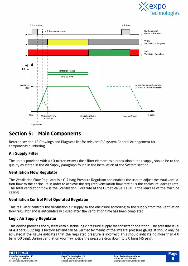
Section 5: Main Components
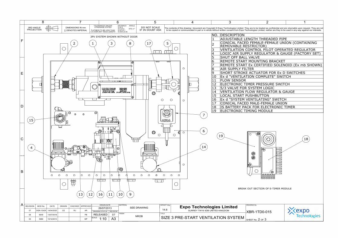
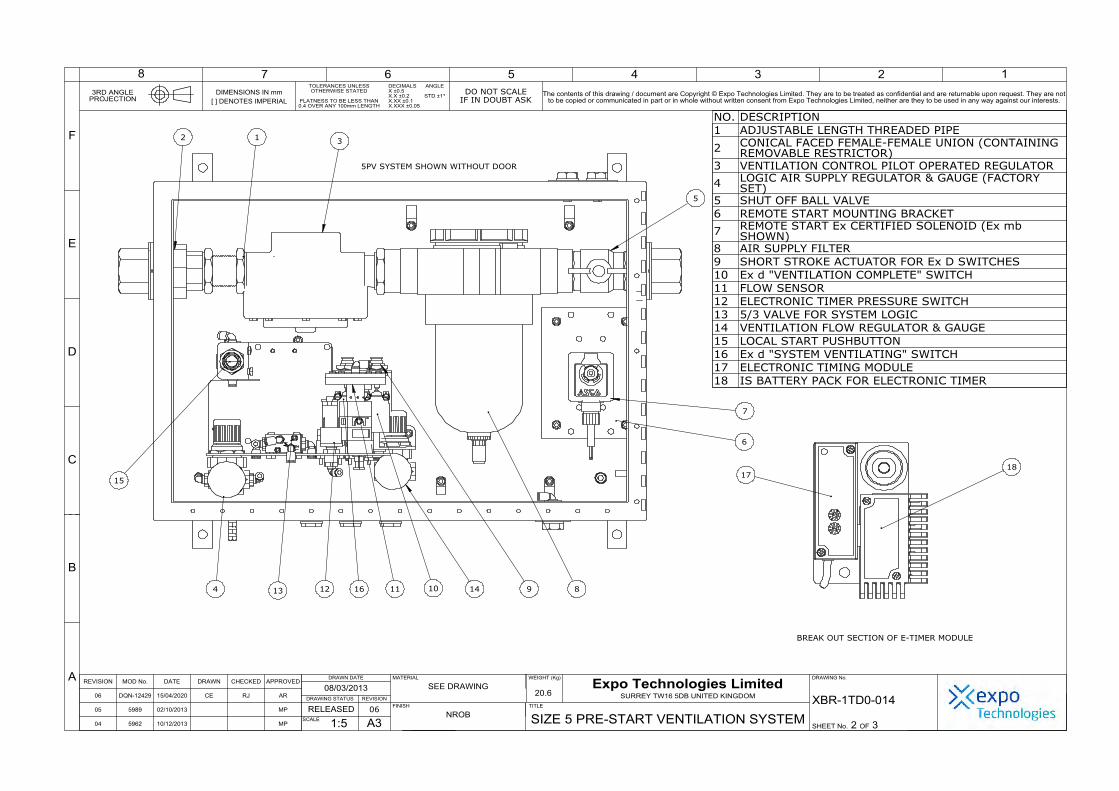
Refer to section 12 Drawings and Diagrams list for relevant PV system General Arrangement for components numbering.
Air Supply Filter
The unit is provided with a 40-micron water / dust filter element as a precaution but air supply should be to thequality as stated in the Air Supply paragraph found in the Installation of the System section.
Ventilation Flow Regulator
The Ventilation Flow Regulator is a 0-7 barg Pressure Regulator and enables the user to adjust the total ventila-tion flow to the enclosure in order to achieve the required ventilation flow rate plus the enclosure leakage rate.The total ventilation flow is the (Ventilation Flow rate at the Outlet Valve +10%) + the leakage of the machinecasing.
Ventilation Control Pilot Operated Regulator
This regulator controls the ventilation air supply to the enclosure according to the supply from the ventilationflow regulator and is automatically closed after the ventilation time has been completed.
Logic Air Supply Regulator
This device provides the system with a stable logic pressure supply for consistent operation. The pressure levelof 4.0 barg (60 psig) is factory set and can be verified by means of the integral pressure gauge. It should only beadjusted if the gauge indicates that the regulated pressure is incorrect. This should indicate no more than 4.0barg (60 psig). During ventilation you may notice the pressure drop down to 3.0 barg (45 psig).
ML513 | v13 Page8
Expo Technologies UKT: +44 (0) 20 8398 8011E: [email protected]
Expo Technologies UST: +1 (440) 247 5314E:[email protected]
Expo Technologies ChinaT: +86 532 8906 9858E: [email protected]
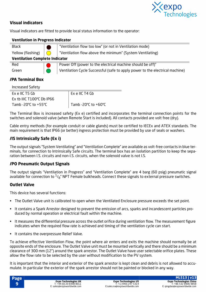
Visual indicators
Visual indicators are fitted to provide local status information to the operator:
/PA Terminal Box
The Terminal Box is increased safety (Ex e) certified and incorporates the terminal connection points for theswitches and solenoid valve (when Remote Start is included). All contacts provided are volt free (dry).
Cable entry methods (for example conduit or cable glands) must be certified to IECEx and ATEX standards. Themain requirement is that IP66 (or better) ingress protection must be provided by use of seals or washers.
/IS Intrinsically Safe (Ex i)
The output signals “System Ventilating” and “Ventilation Complete” are available as volt-free contacts in blue ter-minals, for connection to Intrinsically Safe circuits. The terminal box has an isolation partition to keep the sepa-ration between I.S. circuits and non-I.S. circuits, when the solenoid valve is not I.S.
/PO Pneumatic Output Signals
The output signals “Ventilation in Progress” and “Ventilation Complete” are 4 barg (60 psig) pneumatic signalavailable for connection to 1/8” NPT Female bulkheads. Connect these signals to external pressure switches.
Outlet Valve
This device has several functions:
• The Outlet Valve unit is calibrated to open when the Ventilated Enclosure pressure exceeds the set point.
• It contains a Spark Arrestor designed to prevent the emission of arcs, sparks and incandescent particles pro-duced by normal operation or electrical fault within the machine.
• It measures the differential pressure across the outlet orifice during ventilation flow. The measurement figure indicates when the required flow rate is achieved and timing of the ventilation cycle can start.
• It contains the overpressure Relief Valve.
To achieve effective Ventilation Flow, the point where air enters and exits the machine should normally be atopposite ends of the enclosure. The Outlet Valve unit must be mounted vertically and there should be a minimumclearance of 300 mm (12”) around the spark arrestor. The Outlet Valve have user selectable orifice plates. Theseallow the flow rate to be selected by the user without modification to the PV system.
It is important that the interior and exterior of the spark arrestor is kept clean and debris is not allowed to accu-mulate. In particular the exterior of the spark arrestor should not be painted or blocked in any way.
Ventilation in Progress Indicator
Black “Ventilation flow too low” (or not in Ventilation mode)
Yellow (flashing) “Ventilation flow above the minimum” (System Ventilating)
Ventilation Complete Indicator
Red Power Off (power to the electrical machine should be off)”
Green Ventilation Cycle Successful (safe to apply power to the electrical machine)
Increased Safety
Ex e IIC T5 Gb Ex tb IIIC T100ºC Db IP66Tamb -20ºC to +55ºC
Ex e IIC T4 Gb
Tamb -20ºC to +60ºC
Page9
ML513 | v13Expo Technologies UK
T: +44 (0) 20 8398 8011E: [email protected]
Expo Technologies UST: +1 (440) 247 5314
Expo Technologies ChinaT: +86 532 8906 9858

Section 6: Installation of the System
The Pre-Start Ventilation System must be installed by a competent person in accordance with relevant standards,such as IEC/EN 60079-14 and 60079-19. The installation must strictly adhere to the current standards that ap-plies to the installation of Intrinsically Safe, Increased Safety and Type “n” apparatus. Copies of the CurrentStandard can be purchased from Expo Technologies or B.S.I or relevant local code / Standard.
The Pre-Start Ventilation system should be installed either directly on, or close to the machine. It should be installed such that the system indicators and certification labels are in view.
All parts of the system carry a common serial number. If installing more than one system, ensure that this commonality is maintained within each system installed.
Air Supply Quality
The Pre-Start Ventilation System should be connected to a protective gas supply, which is suitable for ventila-tion.
The supply pipe connections to the Pre-Start Ventilation System are:
The size of the input pipe should be appropriate for the maximum input ventilation flow rate for the application.
The air supply must be regulated at a pressure less than the maximum stated inlet pressure.
The air supply must be: clean, non-flammable and from a non-hazardous location. It must comply with BS ISO8573-1: 2001 Class 2.2.1 or equivalent local standards. This is typically referred to as Instrument Air Quality. Al-though equipment will operate with lower air quality, the operational life of the system will be adversely affect-ed. The equipment that is being protected by the Pre-Start Ventilation may also suffer because of poor air quality.
* For applications where Tamb 0oC, the air supply should be Class 2.1.1 with humidity of -70oC pressure dewpoint.
When an inert gas is being used to supply the ventilation system, risk of asphyxiation exists. Refer to ApplicationSuitability section.
Before connecting the air supply to the Pre-Start Ventilation System, the supply pipe work should be flushedthrough with instrument quality air to remove any debris that may remain in the pipes. This must be carried outfor at least 10 seconds for every metre of supply pipe.
The ventilation air from the Pre-Started Ventilation system should be piped within the machine to ensure venti-lation of potential dead air spots.
Warning: The system is fitted with an internal regulator factory set to 4 barg (60 psig) feeding the logicair supply regulator. The correct logic supply pressure is vital to the reliability and calibration of the Pre-Start Ventilation System, therefore should NOT be adjusted.
3PV 5PV 7PV
1/2” NPT (F) 1” NPT (F) 2” NPT (F)
Instrument Air Quality
Solid Particles 0.5 mm < particle size £ 1 mm, maximum 1000 particles / m3
Residual Water 1mm maximum density, +3oC* pressure dewpoint
Oil Content 0.01 mg / m3 concentration total oil
ML513 | v13 Page10
Expo Technologies UKT: +44 (0) 20 8398 8011E: [email protected]
Expo Technologies UST: +1 (440) 247 5314E:[email protected]
Expo Technologies ChinaT: +86 532 8906 9858E: [email protected]

Pipe Work
If the Pre-Start Ventilation is not connected directly to the machine enclosure, pipe work and fittings used to con-nect the PV system to the machine enclosure should be either metallic or appropriate to the environment intowhich the system is installed. No valve may be fitted in any signal pipe connecting the PV system to the machineenclosure. This pipe work must be fitted in accordance with local codes of practice where relevant.
Multiple Enclosures
This system is suitable for the ventilation of the primary enclosure and its associated terminal boxes.
Power Supplies and their Isolation
All power entering the rotating electrical machine must have a means of isolation. This requirement also appliesto any external power sources that are connected to the equipment such as volt-free (dry) contacts within therotating electrical machine. The electrical installation must conform to the local codes of practice.
Exception
Power to Intrinsically Safe apparatus, or apparatus that is already suitable for use in hazardous locations neednot be isolated by the Pre-Start Ventilation System.
In all cases the user must control the application and the isolation of power to the rotating electrical machine af-ter the Pre-Start Ventilation System shows the “Ventilation Complete” Green signal.
Section 7: Commissioning
Commissioning the System
Refer to the General Arrangement (GA) drawing for the Pre-Start Ventilation system option.
If, after commissioning, the system does not perform as expected, refer to the Fault Finding Section.
Follow these steps:
1. Disconnect the air supply pipe from the inlet to the PV System.
2. Flush the pipe through with instrument quality air to remove any debris. This must be carried out for at least 10 seconds for every metre of supply pipe.
3. Check all connections between the PV system and the Outlet Valve. The Outlet Valve Unit must be fitted cor-rectly with clear path to the ventilation exhaust.
4. Close and re-open the internal shut off valve. See No. 5 in the GA drawing.
5. Check that the internal logic pressure gauge reads 4.0 barg (60 psig). See No. 4 in the GA drawing.
6. Start the ventilation cycle by pushing the Local Start Push Button momentarily until flow is achieved. Or use the Remote Start facility where fitted.
7. The ventilation timer will start as soon as the “System Ventilating” indicator turn from Black to flashing Yellow .
8. Check the time delay between the “System Ventilating” indicator start flashing Yellow , and the “Ventilation Complete” indicator turning from Red to Green . Ventilation time should not be less than the minimum required. Times in excess of the minimum are permitted.
Page11
ML513 | v13Expo Technologies UK
T: +44 (0) 20 8398 8011E: [email protected]
Expo Technologies UST: +1 (440) 247 5314
Expo Technologies ChinaT: +86 532 8906 9858

9. If the “System Ventilating” indicator does not flash Yellow , this indicates low ventilation flow. This can happen with a machine housing with greater than expected leakage.
Increase the ventilation pressure.
10.To correct this, push and hold the Local Start Push Button.
11.Very slowly, open (clockwise) the Ventilation Flow Regulator (See GA drawing for item number), until the indi-cator flashes Yellow .
DO NOT open too quickly as this can allow too much air and over pressurize the enclosure.
12.If after the flow regulator is fully open (the pressure gauge read 4 mbar), and the “System Ventilating” indica-tor does not flash Yellow , refer to next page on “Procedure for increasing air flow”.
When a full ventilation cycle is successfully completed, the “System Ventilating” indicator will turn from flashingYellow to Black .
At the same time the “Ventilation Complete” indicator will turn from Red to Green . The appropriate pneu-matic or electrical signals will coincide with the changes of indicator status.
Once the ventilation time is completed, the ventilation air flow to the machine will stop and the “Ventilation Com-plete” signal will activate.
The system will remain in this mode until the system is either reset or re-started, or the air supply to the systemis isolated.
To reset the “Ventilation Complete” signal, push the Local Start Push Button or energise the Remote Start Sole-noid Valve for one second.
To re-start a ventilation cycle again, push and hold the Local Start Push Button or the Remote Start facility untilthe “System Ventilating” LED’s begin to flash.
Procedure for increasing air flow
It is possible for the enclosure of the rotating electrical machine to have a higher leakage rate than expected,which may affect the PV system’s ability to achieve sufficient air flow to start the ventilation cycle.
See table below to identify if the PV system require the below procedure for removing the fitted restrictor to increase air flow through the system.
Note: This procedure should be carried out by a competent engineer.
Necessary spanner (wrench) sizes
System Orifice in system OutletValve (required flow)
Remove Restrictor (Yes/No)
3PV 1500 NI/min Yes (If unable to achieve sufficient flow to startelectronic timer).
5PV 6000 NI/min Yes
7PV N/A N/A
Components 3PV 5PV
Locknut 32mm 42mm
ML513 | v13 Page12
Expo Technologies UKT: +44 (0) 20 8398 8011E: [email protected]
Expo Technologies UST: +1 (440) 247 5314E:[email protected]
Expo Technologies ChinaT: +86 532 8906 9858E: [email protected]

Union Nut 40mm 54mm
Union 26mm 39mm
Use the spanner (wrench) to loosen the locknut. It should go back 15 - 20mm.
Loosen the union nut and move it back towardsthe locknut as shown
Pull back the right hand half of the union 5 -10mm. The orifice restrictor is in the middle.
Remove the restrictor.
Wind back the right hand union half towards theleft union half.
Note: It is very important to fit the two halves together tightly to avoid leakage.
Lock the two union halves together with the unionnut. Wind back the locknut to it former position.
Components 3PV 5PV
Page13
ML513 | v13Expo Technologies UK
T: +44 (0) 20 8398 8011E: [email protected]
Expo Technologies UST: +1 (440) 247 5314
Expo Technologies ChinaT: +86 532 8906 9858

Section 8: Maintenance of the SystemGeneral maintenance
The maintenance of the system outlined in this manual should be supplemented with any additional require-ments set out in appropriate local codes of practice.
The following checks should be carried out every 6 – 36 months dependent on environment according to IEC / EN 60079-17
• Tests outlined in the Detailed Commissioning section.
• Ensure that the Outlet Valve Unit is free from contamination prior to making any adjustment. To do this:
• Remove large cover plate using a 10 mm spanner (wrench).
• Check that the interior and all components are clean and free from contamination.
• Replace large cover plate.
• Check the condition of the air supply filter element. Clean or replace as necessary.
The following additional checks are recommended at least every 3 years:
Check that:
• Apparatus is suitable for use in the hazardous location.
• There are no unauthorised modifications.
• The air supply is not contaminated.
• The “System Ventilating” and “System Ventilation Complete” signals function correctly.
• Approval labels are legible and not damaged.
• Adequate spares are carried.
• The action on pressure failure is correct.
Maintenance of Electronic Timer
This must be carried out every 3 years.
• The intrinsically safe battery pack associated with the electronic timer should be replaced and the commis-sioning tests repeated.
• After the timing phase has elapsed, the battery may be hot-swapped in the hazardous location without affecting the operation of the Pre-Start Ventilation System
ML513 | v13 Page14
Expo Technologies UKT: +44 (0) 20 8398 8011E: [email protected]
Expo Technologies UST: +1 (440) 247 5314E:[email protected]
Expo Technologies ChinaT: +86 532 8906 9858E: [email protected]

Section 9: Fault Finding
General Information
If there are any problems that cannot be corrected using one of the methods described, please call Expo or yoursupplier for further assistance. If the system is less than 12 months old, parts under warranty should be returnedto Expo for investigation. A full report of the fault and the system serial number should accompany the parts.
It is common for problems with the Pre-Start Ventilation System to be caused by contamination of the air supplywith oil, water or dirt. To prevent these problems, the air supply must contain a dust filter and a water filter. Thiswill ensure that the air is instrument quality and protect both the ventilation system and the equipment beingventilated. This filtration system is not provided by Expo and must be sourced separately.
Contamination can enter the system from a number of sources. To prevent this, it is essential that the proceduresdescribed in the Installation section are carried out prior to first use of the system. These procedures should alsobe carried out following any disconnection and re-connection of the pipe work. Failure to perform these proce-dures may cause damage to the system that will not be covered by the warranty.
The system has been designed for ease of fault finding and the many of the components fitted are plug-in orchassis mounted. Check components by substitution only after establishing that such action is necessary.
Before carrying out the fault finding procedures, ensure that:
• Both the main air pressure to the system and the regulated pressure to the logic manifold are as specified on the settings sheet.
• Air pressure does not drop below the minimum supply pressure during ventilation; the majority of faults reported are due to insufficient air supply during the ventilation cycle.
Pre-Start Ventilation System has sufficient flow but no “System Ventilating” signal.
Fault Location Cause Solution
Battery Pack. The battery pack is discharged. • Battery needs replacement.Consult Expo Technologies.
“System Ventilating” switch.
• Stroke actuator faulty.
• Ex d system ventilating switch is faulty.
• Check the actuation of switch by the “Short Stroke Actuator for Ex d Switch”. Refer to relevant General Arrangement (GA) drawing.
• If Stroke Actuator is not moving while the system is ventilating, the actuator may require replacement. Consult Expo Technologies.
• If Stroke Actuator is working, check that the switch is closing.
• If it is not closing, it needs to be replaced.
• If it is closing but no signal is present, the switch needs replacement. Consult Expo Technologies
Electronic Timer The Electronic Timer is faulty • Needs replacement. Consult Expo.
This should be done by a competent Ser-vice Engineer.
Page15
ML513 | v13Expo Technologies UK
T: +44 (0) 20 8398 8011E: [email protected]
Expo Technologies UST: +1 (440) 247 5314
Expo Technologies ChinaT: +86 532 8906 9858

Ventilation does not start or fails to complete
This is common due to the smaller pipe diameter or smaller compressor.
Ventilation Time Insufficient
This can occur if the Electronic Timer Selector Switches have not been set correctly.
Fault Location Cause Solution
Air Supply Pressure Air supply pressure fall below4 barg (60 psig).
• Check that the air supply pressure is not below the specified minimum pressure during ventilation.
• Increase air pressure. The pressure gauge should be above 4 barg (60 psig) during ventilation.
• or replace main air filter. Consult Expo Technologies.
Machine could have agreater leakage rate thanexpected
Insufficient air supply to rotating electrical machineenclosure.
• Slowly turn the Ventilation Flow Regu-lator to increase the air flow.
• Do this until the “Ventilation in Progress” indicator is activated. Indicator should turn from “Black ” to “Flashing Yellow ”
• This indicates correct Ventilation Flow.
• If the problem is not solved, refer to the “Procedure for increasing air flow” in the Commissioning section.
Remote Solenoid Valve Not functioning • Check all connections from the PV sys-tem to the Remote Start control, conti-nuity and supply voltage where possible.
• Make sure all connections are secure and terminated correctly.
• If all these appear to be correct, then check the operation of the system by using the Local Start Push Button.
• If the Local Start Push Button successfully starts a ventilation cycle, the Solenoid Valve needs replacement.
Fault Location Cause Solution
Electronic Timer SelectorSwitch
Not set correctly • Make sure the Electronic Timer Selector Switch is correct to the required setting.
Electronic Timer is faulty
• Replacement necessary
• This should be fitted by a competent Service Engineer.
ML513 | v13 Page16
Expo Technologies UKT: +44 (0) 20 8398 8011E: [email protected]
Expo Technologies UST: +1 (440) 247 5314E:[email protected]
Expo Technologies ChinaT: +86 532 8906 9858E: [email protected]

Flow Sensor Calibration
Contact Expo Technologies for new Ventilation Flow Sensor if the sensor is out of calibration.
Section 10: Recommended Spares List
Section 11: Glossary
Part Number Description
HF1-A03N-008 Filter kit for HF1-A03N-009 filter - size 3
HF1-A03N-007 Filter kit for HF1-A03N-006 filter - size 5
HF1-A03N-002 Filter kit for HF1-A03N-001 filter - size 7
S0191/025 Ex d II switch SPCO
AGE-SW0Z-035 IS switch SPCO
S0030/606 Ventilation Flow sensor, must be factory set to the value as stated on theCustomer Test and Inspection Sheet
ETM-IS31-001 IS battery pack for Electronic Timer
(only applicable to systems with battery powered timer)
KPV-RS01 24VDC Remote Start Solenoid Kit
KPV-RS02 110VAC Remote Start Solenoid Kit
KPV-RS03 230VAC Remote Start Solenoid Kit
KPV-RS10 12VDC (IS) Remote Start Solenoid Kit
KPV-RS11 24VDC (IS) Remote Start Solenoid Kit
Acronym Definition
PV Pre-Start Ventilation system
ET Electronic Timer
LS Local Start Pushbutton
RS Remote Start (Solenoid valve)
IS Intrinsically Safe
PA Permissive Alarm
OV Pneumatically Operated Outlet Valve
PO Pneumatic Output
Page17
ML513 | v13Expo Technologies UK
T: +44 (0) 20 8398 8011E: [email protected]
Expo Technologies UST: +1 (440) 247 5314
Expo Technologies ChinaT: +86 532 8906 9858
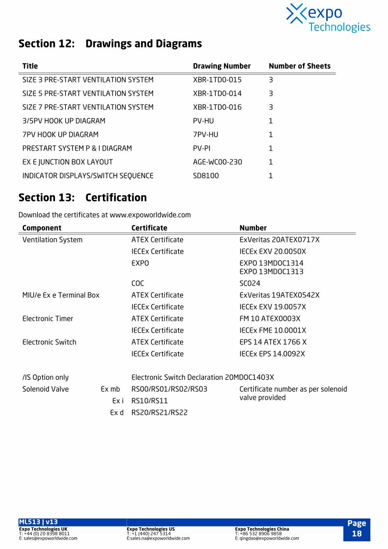
Section 12: Drawings and Diagrams
Section 13: Certification
Download the certificates at www.expoworldwide.com
Title Drawing Number Number of Sheets
SIZE 3 PRE-START VENTILATION SYSTEM XBR-1TD0-015 3
SIZE 5 PRE-START VENTILATION SYSTEM XBR-1TD0-014 3
SIZE 7 PRE-START VENTILATION SYSTEM XBR-1TD0-016 3
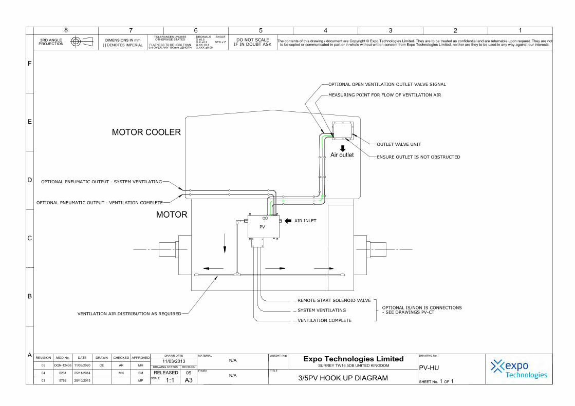
3/5PV HOOK UP DIAGRAM PV-HU 1
7PV HOOK UP DIAGRAM 7PV-HU 1
PRESTART SYSTEM P & I DIAGRAM PV-PI 1
EX E JUNCTION BOX LAYOUT AGE-WC00-230 1
INDICATOR DISPLAYS/SWITCH SEQUENCE SD8100 1
Component Certificate Number
Ventilation System ATEX Certificate ExVeritas 20ATEX0717X
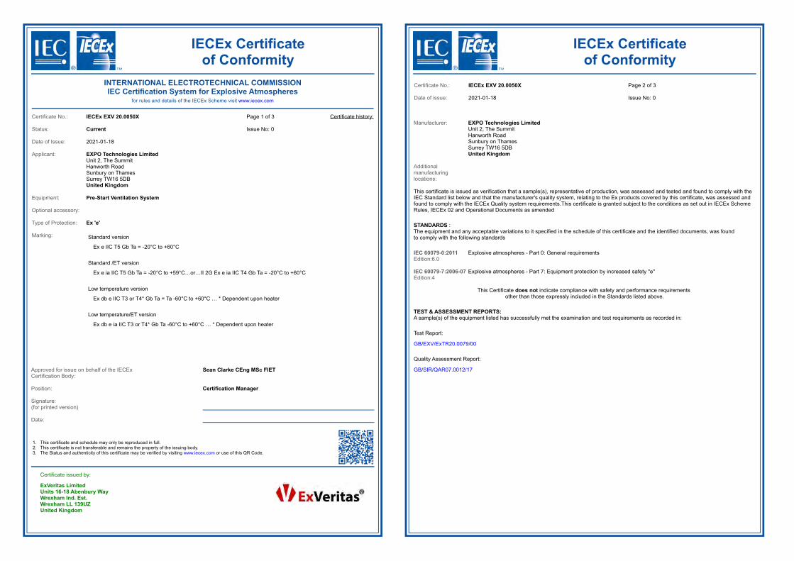
IECEx Certificate IECEx EXV 20.0050X
EXPO EXPO 13MDOC1314EXPO 13MDOC1313
COC SC024
MIU/e Ex e Terminal Box ATEX Certificate ExVeritas 19ATEX0542X
IECEx Certificate IECEx EXV 19.0057X
Electronic Timer ATEX Certificate FM 10 ATEX0003X
IECEx Certificate IECEx FME 10.0001X
Electronic Switch ATEX Certificate EPS 14 ATEX 1766 X
IECEx Certificate IECEx EPS 14.0092X
/IS Option only Electronic Switch Declaration 20MDOC1403X
Solenoid Valve Ex mb RS00/RS01/RS02/RS03 Certificate number as per solenoid valve providedEx i RS10/RS11
Ex d RS20/RS21/RS22
ML513 | v13 Page18
Expo Technologies UKT: +44 (0) 20 8398 8011E: [email protected]
Expo Technologies UST: +1 (440) 247 5314E:[email protected]
Expo Technologies ChinaT: +86 532 8906 9858E: [email protected]


DU
RIN
GVEN
TIL
ATIO
N
YELLO
W
(FLASH
ING
)REDIN
DIC
ATO
RS
VEN
TIL
ATIO
N
CO
MPLETE
-N
ORM
AL
OPERATIO
N
BLACK
GREEN
IND
ICATO
RS
REM
OTE
START
SO
LEN
OID
VALVE
REM
OTE
START
SO
LEN
OID
VALVE
TERM
INAL
BO
X
TERM
INAL
BO
X
TERM
INAL
BO
X
TERM
INAL
BO
X
TERM
INAL
BO
X
GREY
IND
ICATO
RS
BLACK
AIR
ON
(NO
VEN
TIL
ATIN
G)
GREY
RED
BLACK
BROWN
87
64-5
(CLO
SED
)
REM
OTE
START
SO
LEN
OID
VALVE
BROWN
BROWN
BLACK
54
3
BLUE
21
TERM
INAL
BO
X
1-3
(OPEN
)
1-2
(CLO
SED
)
4-6
(OPEN
)
SW
ITCH
-IND
ICATO
RSEQ
UEN
CE
DIA
GRAM
FO
R
PRESTART
VEN
TIL
ATIO
NSYSTEM
S
GREY
GREY
BLACK
BROWN
87
6
BROWN
BROWN
BLACK
54
3
BLUE
21
GREY
GREY
BLACK
BROWN
87
6
BROWN
BROWN
BLACK
54
3
BLUE
21
4-5
(CLO
SED
)
1-3
(CLO
SED
)
1-2
(OPEN
)
4-6
(OPEN
)
4-5
(OPEN
)
1-3
(OPEN
)
1-2
(CLO
SED
)
4-6
(CLO
SED
)
B
C
D
E
F
8 57 6 4 3 12
3RD ANGLEPROJECTION
The contents of this drawing / document are Copyright © Expo Technologies Limited. They are to be treated as confidential and are returnable upon request. They are notto be copied or communicated in part or in whole without written consent from Expo Technologies Limited, neither are they to be used in any way against our interests.
DIMENSIONS IN mm
[ ] DENOTES IMPERIAL
WEIGHT (Kg)
TITLE
DO NOT SCALE
IF IN DOUBT ASK
FINISH
MATERIAL
A3SCALE
DRAWING STATUS
A
TOLERANCES UNLESSOTHERWISE STATED
FLATNESS TO BE LESS THAN0.4 OVER ANY 100mm LENGTH
ANGLE
STD ±1°
MOD #REVISION DRAWN CHECKED APPROVEDDATEDRAWN DATE
SURREY TW16 5DB UNITED KINGDOM
Expo Technologies LimitedDRAWING No.
REVISION
DECIMALSX ±0.5X.X ±0.2X.XX ±0.1X.XXx ±0.05
SHEET No. OF 11
SD8100
INDICATOR DISPLAYS/SWITCH SEQUENCE03CERT REL
N.T.S
DQN-12436
5962
DRAWN
CE AR MH
MLC
CB MN MP
03
02
01
05/06/201311/05/20
24/10/13
05/06/13

xVeritas 20 ATEX 0717 X Issue 0
ced in its entirety and without any change, schedule included. ting to this certificate, contact [email protected].
verinsmindevej 6, 4420 Regstrup, Denmark. trademark, unauthorised use will lead to prosecution.
Page 2 of 5
FO-CB-37 V1
+60°C
to +59°C…or…II 2G Ex e ia IIC T4 Gb Ta = -20°C to +60°C
Ta -60°C to +60°C … * Dependent upon heater
a -60°C to +60°C … * Dependent upon heater
ntilation System designation table after the DXXX option:
tive System
System is intended to provide pre-start ventilation for motors in a a control unit and a relief valve, which contains various electrical, he control of ventilation gas to an associated motor (not included in edetermined time. Alternative arrangements include the provision of e option for extended or continuous ventilation. A low temperature heater and thermostat.
ndicates the order of the model number. This disambiguation ing the characteristic letters which are defined in the table overleaf.
art Number: a b c d e
On behalf of ExVeritas Peter Lauritzen Managing Director
This certificate may only be reproduced in its entirety and without any change, schedule included. The certificate is only valid when it carries an original signature.
For help or assistance relating to this certificate, contact [email protected]. ExVeritas ApS, Severinsmindevej 6, 4420 Regstrup, Denmark.
ExVeritas® is a registered trademark, unauthorised use will lead to prosecution.
Page 1 of 5 FO-CB-37 V1
1 EU - Type Examination Certificate 2 Equipment intended for use in Potentially Explosive Atmospheres Directive 2014/34/EU 3 Certificate Number: ExVeritas 20 ATEX 0717 X Issue: 0 4 Equipment: Pre-Start Ventilation System 5 Manufacturer: EXPO Technologies Limited 6 Address: Unit 2, The Summit, Hanworth Road, Sunbury on Thames, Surrey,
TW16 5DB, United Kingdom
7 This equipment and any acceptable variation thereto are specified in the schedule to this certificate and the documents therein referred to.
8 ExVeritas, Notified Body number 2804 in accordance with Article 17 of the Council Directive 2014/34/EU
of 26 February 2014, certifies that this equipment or protective system has been found to comply with the Essential Health and Safety Requirements relating to design and construction of equipment and protective systems for use in potentially explosive atmospheres given in Annex II to the Directive
9 Compliance with the applicable Essential Health and Safety Requirements has been assured by
compliance with the following Standards and section 16 of this certificate:
EN 60079-0: 2012+A11:2013 EN 60079-7: 2007
10 If the sign “X” is placed after the certificate number, it indicates that the equipment is subject to special conditions for safe use specified in the schedule to this certificate.
11 This EU-Type Examination Certificate relates only to the design, construction, examination and tests of
the specified equipment or protective system in accordance to the Directive 2014/34/EU. Further requirements of the Directive apply to the manufacturing process and supply of this equipment or protective system. These are not covered by this certificate.
12 The marking of the equipment shall be in consonance with the prescribed marking in the description (section 12.1, overleaf)
Schedule
Certificate: E
This certificate may only be reproduFor help or assistance rela
ExVeritas ApS, SeExVeritas® is a registered
12.1 Marking Standard version
II 2G Ex e IIC T5 Gb Ta = -20°C to
Standard version with /ET or /ES
II 2G Ex e ia IIC T5 Gb Ta = -20°C
Low temperature version
II 2G Ex db e IIC T3 or T4* Gb Ta =
Low temperature version with /ET or /ES
II 2G Ex db e ia IIC T3 or T4* Gb T
The following line is added to the Pre-start Ve LT = Low Temperature option 13 Description of Equipment or Protec
The Expo Technologies Pre-Start Ventilationhazardous area. The equipment consists of mechanical, and pneumatic components for tthis certificate), at a set flow rate and for a pran electronic timer, a solenoid valve, and thversion is available which includes a certified The following representative placeholder icomprehensively defines the part numbers us
P

xVeritas 20 ATEX 0717 X Issue 0
ced in its entirety and without any change, schedule included. ting to this certificate, contact [email protected].
verinsmindevej 6, 4420 Regstrup, Denmark. trademark, unauthorised use will lead to prosecution.
Page 4 of 5
FO-CB-37 V1
istory:
sue Comment Issue of EXV prime certificate. Certificate transfer from
Sira 13ATEX1083X Issue 1. See previous certificate for full revision history. This revision includes the code for the part number “/ES”.
Drawing No. Rev. Level Rev. Date
ystem. SD8036 03 11/11/2020
SD8038 06 11/11/2020
SD8043 04 25/11/2020
SD8044 06 11/11/2020
SD8049 03 11/11/2020
SD8066 06 11/11/2020
SD8076 02 25/11/2020
. SD8312 02 11/11/2020
SD8313 02 11/11/2020
is as a pre-start ventilation system. It is the user’s responsibility to equipment when in use.
in RTDs or simple resistive switches. It is the user’s responsibility to suitably certified intrinsically safe circuits.
temperature version, shall be protected by a safety related system ised if the temperature of the air inlet or controller unit falls below -Ds that are fitted to the control unit to provide the appropriate level
ational safety of Cat 3 according to EN 954-1 for ATEX Category 2 se RTDs have not been assessed as a safety related device in ve 94/9/EC.
an intrinsically safe solenoid valve, the user must ensure that any he parameters of the solenoid valve certificate.
Schedule
Certificate: ExVeritas 20 ATEX 0717 X Issue 0
This certificate may only be reproduced in its entirety and without any change, schedule included. For help or assistance relating to this certificate, contact [email protected].
ExVeritas ApS, Severinsmindevej 6, 4420 Regstrup, Denmark. ExVeritas® is a registered trademark, unauthorised use will lead to prosecution.
Page 3 of 5
FO-CB-37 V1
Characteristic letter Definition
a - Size or Capacity 1 = Flow rate up to 225 l/min 2 = Flow rate up to 450 l/min 3 = Flow rate up to 1500 l/min 4 = Flow rate up to 3000 l/min 5 = Flow rate up to 6000 l/min 6 = Flow rate up to 9000 l/min 7 = Flow rate up to 14000 l/min
b - Pre-start Ventilation Type PV = Pre-start Ventilation PP = Pre-start Ventilation (alternative)
c - Control Unit Enclosure Material/Mounting Configuration
al = Aluminium alloy cs = Mild steel, painted ss = Stainless steel bp = Back Plate only co = Chassis only pm = Panel mounting nm = Non-Metallic
d - Start Option LS = Local start using start switch on PV/PP system RS## = Remote start using Ex rated solenoid kit
e - Fitting Option A = ANSI flange connection fittings used D = DIN flange connection fittings used B = BSP Pipe connection fittings used N = NPT Pipe connection fittings used # = letter showing non-certified pipe fitting
Option codes (Added only if used) FM Flow Meter(s) fitted on enclosure to indicate ventilation flow IS Internal Switches suitable for Ex i circuits. MR Mechanically Resets ventilation reset signal. ER Electronically Resets ventilation reset signal. PR Pneumatically Resets ventilation reset signal. MT Mechanical Timing used to time pre-start ventilation cycle PT Pneumatic Timing used to time pre-start ventilation cycle ET Electronic Timing used to time pre-start ventilation cycle HP High Pressure sensor fitted to prevent over pressure. OV Outlet valve, pneumatically operated. PA "Ex" switch(es) built-in, with/without "Ex" junction box. SP Secondary Pre-Ventilation supply options. SS Separate Supply for Protective gas and Logic air. TW Twin (or more) outputs for two or more separate ventilated enclosures ventilated in parallel. HS High Supply Pressure up to 16 Bar. CV Ventilation sustained indefinitely after completion of ventilation cycle EV Ventilation extended for predefined period of time after completion of ventilation cycle DXXX Special design, no certification related options LT Low Temperature option /ES Electronic timer with EPPS /ET Electronic timer with the battery
Schedule
Certificate: E
This certificate may only be reproduFor help or assistance rela
ExVeritas ApS, SeExVeritas® is a registered
14 Descriptive Documents
14.1 Associated Report and Certificate H
Report Number Cert Issue Date IsR2909/A/1 19/10/2020 0
14.2 Compliance Drawings:
Issue 0 Title
Ventilation Complete Reset Options for PV s
Pre-start Ventilation Housing.
Pre-start Ventilation Model Numbers.
Circuit Diagram for PV/PP System.
High Pressure Option ‘HP’.
Timing Options for PV System.
Certification Label.
PV & PP System Low Temp. Wiring (Typical)
PV & PP Low Temperature Housing.
15 Conditions of Certification
15.1 Special Conditions for Safe Use
1. The intended use of this equipment ensure the correct functionality of the
2. The equipment enclosure may conta
ensure that these are connected into
3. The Pre-Start Ventilation System, lowthat ensures that it cannot be energ20°C. This system shall utilise the RTof safety integrity, i.e. a level of oper(Zone 1) applications; note that theaccordance with EHSR 1.5 of Directi
4. When the equipment is provided with
associated line inductance is within t

Schedule
Certificate: ExVeritas 20 ATEX 0717 X Issue 0
This certificate may only be reproduced in its entirety and without any change, schedule included. For help or assistance relating to this certificate, contact [email protected].
ExVeritas ApS, Severinsmindevej 6, 4420 Regstrup, Denmark. ExVeritas® is a registered trademark, unauthorised use will lead to prosecution.
Page 5 of 5
FO-CB-37 V1
15.2 Conditions for Use (Routine Tests) 16 Essential Health and Safety Requirements
Essential Health and Safety Requirements are addressed by the standards listed in section 9 and where required the report listed in section 14.1
The manufacturer shall inform the Notified Body of any modifications to the design of the product described by this schedule.
IECEx Certificateof Conformity
Page 2 of 3
Issue No: 0
resentative of production, was assessed and tested and found to comply with the system, relating to the Ex products covered by this certificate, was assessed and ts.This certificate is granted subject to the conditions as set out in IECEx Scheme
in the schedule of this certificate and the identified documents, was found
eral requirements
ipment protection by increased safety "e"
e compliance with safety and performance requirements essly included in the Standards listed above.
e examination and test requirements as recorded in:
IECEx Certificateof Conformity
INTERNATIONAL ELECTROTECHNICAL COMMISSIONIEC Certification System for Explosive Atmospheres
for rules and details of the IECEx Scheme visit www.iecex.com
Certificate No.: IECEx EXV 20.0050X
Status: Current
Date of Issue: 2021-01-18
Applicant: EXPO Technologies LimitedUnit 2, The Summit Hanworth Road Sunbury on Thames Surrey TW16 5DB United Kingdom
Equipment: Pre-Start Ventilation System
Optional accessory:
Type of Protection: Ex 'e'
Marking:
Page 1 of 3
Issue No: 0
Certificate history:
Standard version
Ex e IIC T5 Gb Ta = -20°C to +60°C
Standard /ET version
Low temperature version
Low temperature/ET version
1.2.3.
Approved for issue on behalf of the IECEx Certification Body:
Position:
Signature:(for printed version)
Date:
This certificate and schedule may only be reproduced in full.This certificate is not transferable and remains the property of the issuing body.The Status and authenticity of this certificate may be verified by visiting www.iecex.com or use of this QR Code.
Certificate issued by:
ExVeritas LimitedUnits 16-18 Abenbury Way Wrexham Ind. Est. Wrexham LL 139UZ United Kingdom
Sean Clarke CEng MSc FIET
Certification Manager
Certificate No.: IECEx EXV 20.0050X
Date of issue: 2021-01-18
Manufacturer: EXPO Technologies LimitedUnit 2, The Summit Hanworth Road Sunbury on Thames Surrey TW16 5DB United Kingdom
Additional manufacturing locations:
This certificate is issued as verification that a sample(s), repIEC Standard list below and that the manufacturer's qualityfound to comply with the IECEx Quality system requiremenRules, IECEx 02 and Operational Documents as amended
STANDARDS :The equipment and any acceptable variations to it specifiedto comply with the following standards
IEC 60079-0:2011 Edition:6.0
Explosive atmospheres - Part 0: Gen
IEC 60079-7:2006-07 Edition:4
Explosive atmospheres - Part 7: Equ
This Certificate does not indicatother than those expr
TEST & ASSESSMENT REPORTS:A sample(s) of the equipment listed has successfully met th
Test Report:
Quality Assessment Report:
GB/EXV/ExTR20.0079/00
GB/SIR/QAR07.0012/17

e 0
8, Abenbury Way, Wrexham Industrial Estate, FO-CB-34 V1 am, United Kingdom LL13 9UZ.
System is intended to provide pre-start ventilation for motors in a a control unit and a relief valve, which contains various electrical, the control of ventilation gas to an associated motor (not included predetermined time. Alternative arrangements include the provision he option for extended or continuous ventilation. A low temperature heater and thermostat.
indicates the order of the model number. This disambiguation sing the characteristic letters which are defined in the table overleaf.
Part Number: a b c d e
Definition
1 = Flow rate up to 225 l/min 2 = Flow rate up to 450 l/min 3 = Flow rate up to 1500 l/min 4 = Flow rate up to 3000 l/min 5 = Flow rate up to 6000 l/min 6 = Flow rate up to 9000 l/min 7 = Flow rate up to 14000 l/min
PV = Pre-start Ventilation PP = Pre-start Ventilation (alternative)
al = Aluminium alloy cs = Mild steel, painted ss = Stainless steel bp = Back Plate only co = Chassis only pm = Panel mounting nm = Non-Metallic
LS = Local start using start switch on PV/PP system RS## = Remote start using Ex rated solenoid kit
A = ANSI flange connection fittings used D = DIN flange connection fittings used B = BSP Pipe connection fittings used N = NPT Pipe connection fittings used # = letter showing non-certified pipe fitting
indicate ventilation flow ircuits. et signal. et signal. set signal. -start ventilation cycle
-start ventilation cycle start ventilation cycle ent over pressure. d. t "Ex" junction box. ptions. and Logic air. ore separate ventilated enclosures ventilated in parallel. . ter completion of ventilation cycle period of time after completion of ventilation cycle ted options
IECEx Certificateof Conformity
Certificate No.: IECEx EXV 20.0050X
Date of issue: 2021-01-18
Page 3 of 3
Issue No: 0
EQUIPMENT: Equipment and systems covered by this Certificate are as follows:
SPECIFIC CONDITIONS OF USE: YES as shown below:
Annex:
IECEx Certificate Annex_1.pdf
The Expo Technologies Pre-Start Ventilation System is intended to provide pre-start ventilation for motors in a hazardous area. The equipment consists of a control unit and a relief valve, which contains various electrical, mechanical, and pneumatic components for the control of ventilation gas to an associated motor (not included in this certificate), at a set flow rate and for a predetermined time. Alternative arrangements include the provision of an electronic timer, a solenoid valve, and the option for extended or continuous ventilation. A low temperature version is available which includes a certified heater and thermostat
Please see Annex for part number disambiguation.
1.
2.
3.
4.
the equipment when in use.
into suitably certified intrinsically safe circuits.The Pre-Start Ventilation System, low temperature version, shall be protected by a safety related system that ensures that it cannot be energised if the temperature of the air inlet or controller unit falls below -20°C. This system shall utilise the RTDs that are fitted to the control unit to provide the appropriate level of safety integrity, i.e. a level of operational safety of Cat 3 according to EN 954-1 for ATEX Category 2 (Zone 1) applications; note that these RTDs have not been assessed as a safety related device in accordance with EHSR 1.5 of Directive 94/9/EC.When the equipment is provided with an intrinsically safe solenoid valve, the user must ensure that any associated line inductance is within the parameters of the solenoid valve certificate.
Annex to: IECEx EXV 20.0050X Issu
Page 1 of 2 ExVeritas, Units 16-1Wrexh
Description Continued: The Expo Technologies Pre-Start Ventilationhazardous area. The equipment consists ofmechanical, and pneumatic components forin this certificate), at a set flow rate and for a of an electronic timer, a solenoid valve, and tversion is available which includes a certified The following representative placeholder comprehensively defines the part numbers u
Characteristic letter
a - Size or Capacity
b - Pre-start Ventilation Type
c - Control Unit Enclosure Material/Mounting Configuration
d - Start Option
e - Fitting Option
Option codes (Added only if used) FM Flow Meter(s) fitted on enclosure toIS Internal Switches suitable for Ex i cMR Mechanically Resets ventilation resER Electronically Resets ventilation resPR Pneumatically Resets ventilation reMT Mechanical Timing used to time prePT Pneumatic Timing used to time preET Electronic Timing used to time pre-HP High Pressure sensor fitted to prevOV Outlet valve, pneumatically operatePA "Ex" switch(es) built-in, with/withouSP Secondary Pre-Ventilation supply oSS Separate Supply for Protective gasTW Twin (or more) outputs for two or mHS High Supply Pressure up to 16 BarCV Ventilation sustained indefinitely afEV Ventilation extended for predefinedDXXX Special design, no certification relaLT Low Temperature option /ES Electronic timer with EPPS /ET Electronic timer with the battery
Annex to: IECEx EXV 20.0050X Issue 0
Page 2 of 2 ExVeritas, Units 16-18, Abenbury Way, Wrexham Industrial Estate, FO-CB-34 V1 Wrexham, United Kingdom LL13 9UZ.
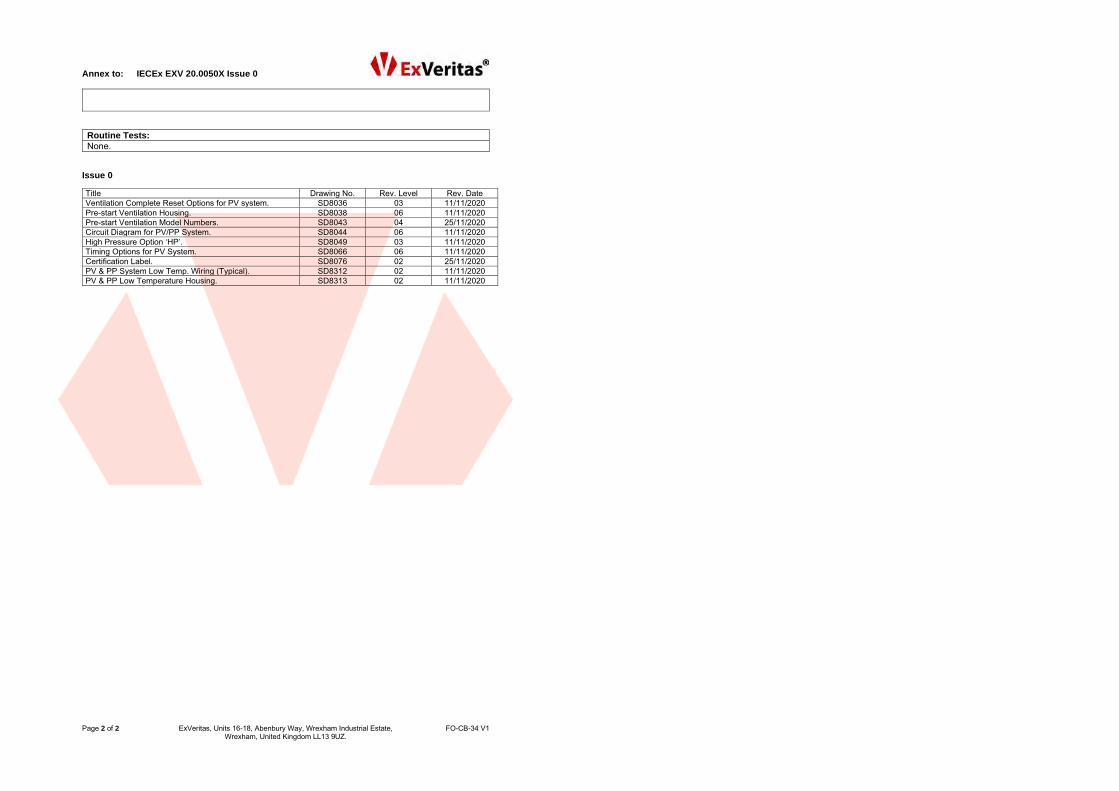
Routine Tests: None.
Issue 0
Title Drawing No. Rev. Level Rev. Date
Ventilation Complete Reset Options for PV system. SD8036 03 11/11/2020
Pre-start Ventilation Housing. SD8038 06 11/11/2020
Pre-start Ventilation Model Numbers. SD8043 04 25/11/2020
Circuit Diagram for PV/PP System. SD8044 06 11/11/2020
High Pressure Option ‘HP’. SD8049 03 11/11/2020
Timing Options for PV System. SD8066 06 11/11/2020
Certification Label. SD8076 02 25/11/2020
PV & PP System Low Temp. Wiring (Typical). SD8312 02 11/11/2020
PV & PP Low Temperature Housing. SD8313 02 11/11/2020

Page 1 of 2 Expo Technologies Ltd Unit 2, The Summit, Hanworth Road, Sunbury on Thames, TW16 5DB, UK T +44 (0)20 8398 8011 F +44 (0)20 8398 8014 E [email protected]
Expo Technologies Ltd. Registered in England No2854600 www.expoworldwide.com
(1) Declaration of Conformity (2) Expo Technologies Document Number EXPO 13MDOC1314 Issue 1 (3) This declaration is issued for the Pre-Start Ventilation Systems
Types 4PP, 6PP, 7PP, 3PV, 5PV & 7PV
(4) Manufacturer: Expo Technologies Ltd Unit 2, The Summit Hanworth Road Sunbury on Thames TW16 5DB U.K.
(5) Pre-Start Ventilation Systems, types 4PP, 6PP, 7PP, 3PV, 5PV or 7PV, including all option
models, are designed to protect rotating electrical machines, by removing any explosive gases which may ignite during the start-up cycle.
(6) The system is suitable for use with Ex e rotating electrical machines in accordance with
EN 60079-7:2015.
(7) Expo Technologies declares that the Pre-Start Ventilation System is fully constructed of pneumatic and mechanical parts, which fulfil all the requirements for Group II Category 2 equipment in accordance with European Directive 2014/34/EU. The construction of the Pre-Start Ventilation System is inherently safe to be used in Zone 1 Hazardous Areas
(8) Depending on the model, the Expo Pre-Start Ventilation System may contain one or more
of the following ATEX certified apparatus, suitable for use in Zone 1 without further assessment: Apparatus ATEX Certificate Marking T amb Indication Limit Switch EPS 14ATEX1766X II 2 G Ex db IIC T6 -20ºC to +60ºC Electronic Timer FM 10ATEX0003X II 1 G Ex ia IIC T5 -20ºC to +59ºC MIU/e Terminal Box ITS 10ATEX37092X II 2 G Ex e IIC T5 -20ºC to +60ºC Ex m Solenoid Valve SIRA BAS98ATEX2168X II 2 G Ex mb IIC Tx Gb* -40ºC to +yyºC* Ex i Solenoid Valve INERIS 03ATEX0249X II 1 G Ex ia IIC T* -40ºC to +yyºC* Ex d Solenoid Valve LCIE 00ATEX6008X II 1 G Ex d IIC T* -40ºC to +100ºC * Refer to installed apparatus for full marking.
(9) The design has been assessed under SIRA Report R29083B/00 and R70087523A and is documented in Expo Technologies Technical Construction File numbers 45054 & 51080. Manufacture is controlled under Sira Quality Assurance Notification Sira 99 ATEX M043
M L Carrillo J P de Beer Certification Manager Technical Director For and on behalf of Expo Technologies Ltd. Sunbury on Thames, UK
MMMMMMMMMMMMMMMMMMMMMM L CarrilloC tifi ti M
Page 2 of 2 Expo Technologies Ltd Unit 2, The Summit, Hanworth Road, Sunbury on Thames, TW16 5DB, UK T +44 (0)20 8398 8011 F +44 (0)20 8398 8014 E [email protected]
Expo Technologies Ltd. Registered in England No2854600 www.expoworldwide.com
Annex to Declaration of Conformity EXPO 13MDOC1314 Issue 1
(10) Expo Technologies declares that the Pre-Start Ventilation Systems are suitable for use with Ex e rotating electrical machines in accordance with: EN 60079-7:2015 Clause 5.2.7.3 requires that the rotating electrical machines shall be assessed for possible air gap sparking. This Clause specifies that an alternative for mitigating the risk of ignition during start up is that “the machine shall allow special measures to be applied during starting, to ensure that its enclosure does not contain an explosive gas atmosphere at the time of starting.” Note 1 to the above Clause on the standard states “Special measures include pre-start ventilation to remove any ignitable accumulation of flammable gases (for example by applying the purging, but not pressurization aspects of IEC 60079-2 in respect of Level of Protection ‘pzc’).”
(11) Given that the standard only refers to special measures, a Pre-start Ventilation System cannot be certified as apparatus for this purpose.
(12) Outlet Valve
The Pre-Start Ventilation System is supplied with an outlet valve, fitted with a spark arrestor and overpressure relief valve. The Outlet Valve shall be fitted to the protected Ex e or Ex n rotating electrical machine, to prevent an internal overpressure above the maximum overpressure rating of the apparatus.
(13) Remote Start The Pre-Start Ventilation System may be remotely started by means of an Ex certified Solenoid Valve. When a Solenoid Valve is used, the following electrical data may be afforded to the system: Power supply 5, 12-24, 50, 110 or 230V dc / ac 50-60 Hz Current Consumption 8 – 16 mA according to valve type and supply voltage
(14) Low Temperature Option - Ambient temperature range Ta -60ºC to +60ºC The Pre-Start Ventilation System may be supplied with an additional, heated, stainless steel enclosure to permit it to be used within an ambient temperature down to -50ºC. This enclosure is fitted with an Ex d heater and an Ex e terminal box for connection of the heater leads. T Class and Gas Group may vary according to the Ex d heater and Ex e or Ex d terminal box classifications, refer to installed apparatus.
(15) Declaration of Conformity History
Issue Date Comment
0 29 October 2013 The release of the initial Declaration of Conformity
1 19 October 2017 This issue covers the following changes:
� IEC 60079-7:2015 has superseded standards IEC 60079-7:2007 and IEC 60079-15:2010
� Update to certificates referenced on item (8)
� Update to ambient temperature range for the Low Temperature Option.
� European Directive updated to 201/34/EU

Page 1 of 2 Expo Technologies Ltd Unit 2, The Summit, Hanworth Road, Sunbury on Thames, TW16 5DB, UK T +44 (0)20 8398 8011 F +44 (0)20 8398 8014 E [email protected]
Expo Technologies Ltd. Registered in England No2854600 www.expoworldwide.com
(1) Declaration of Conformity (2) Expo Technologies Document Number EXPO 13MDOC1313 Issue 1 (3) This declaration is issued for the Pre-Start Ventilation Systems
Types 4PP, 6PP, 7PP, 3PV, 5PV & 7PV
(4) Manufacturer: Expo Technologies Ltd Unit 2, The Summit Hanworth Road Sunbury on Thames TW16 5DB U.K.
(5) Pre-Start Ventilation Systems, types 4PP, 6PP, 7PP, 3PV, 5PV or 7PV, including all option
models, are designed to protect rotating electrical machines, by removing any explosive gases which may ignite during the start-up cycle.
(6) The system is suitable for use with Ex e rotating electrical machines in accordance with
IEC 60079-7:2015.
(7) Expo Technologies declares that the Pre-Start Ventilation System is fully constructed of pneumatic and mechanical parts, which fulfil all the requirements for Zone 1 equipment in accordance with the IECEx regulations. The construction of the Pre-Start Ventilation System is inherently safe to be used in Zone 1 Hazardous Areas
(8) Depending on the model, the Expo Pre-Start Ventilation Systems may contain one or more
of the following IECEx certified apparatus, suitable for use in Zone 1 without further assessment: Apparatus IECEx Certificate Marking T amb Indication Limit Switch IECEx EPS 14.0092X Ex db IIC T6 -20ºC to +60ºC Electronic Timer IECEx FME 10.0001X Ex ia IIC T5 -20ºC to +59ºC MIU/e Terminal Box IECEx ITS 10.0003X Ex e IIC T5 -20ºC to +60ºC Ex m Solenoid Valve IECEx SIR 06.0109X Ex mb IIC Tx Gb* -40ºC to +yyºC* Ex i Solenoid Valve IECEx INE 10.0002X Ex ia IIC T* -40ºC to +yyºC* Ex d Solenoid Valve IECEx LCI 07.0015X Ex d IIC T* -40ºC to +100ºC * Refer to installed apparatus for full marking.
(9) The design has been assessed under SIRA ExTR GB/SIR/ExTR13.0267/00 and GB/SIR/ExTR17.0181/00 and is documented in Expo Technologies Technical Construction File numbers 45054 & 51080.
M L Carrillo J P de Beer Certification Manager Technical Director For and on behalf of Expo Technologies Ltd. Sunbury on Thames, UK
MMMMMMMMMMMMMMMMMMMM L CarrilloC tifi ti M
Page 2 of 2 Expo Technologies Ltd Unit 2, The Summit, Hanworth Road, Sunbury on Thames, TW16 5DB, UK T +44 (0)20 8398 8011 F +44 (0)20 8398 8014 E [email protected]
Expo Technologies Ltd. Registered in England No2854600 www.expoworldwide.com
Annex to Declaration of Conformity EXPO 13MDOC1313 Issue 1
(10) Expo Technologies declares that the Pre-Start Ventilation Systems are suitable for use with Ex e rotating electrical machines in accordance with: IEC 60079-7:2015 Clause 5.2.7.3 requires that the rotating electrical machines shall be assessed for possible air gap sparking. This Clause specifies that an alternative for mitigating the risk of ignition during start up is that “the machine shall allow special measures to be applied during starting, to ensure that its enclosure does not contain an explosive gas atmosphere at the time of starting.” Note 1 to the above Clause on the standard states “Special measures include pre-start ventilation to remove any ignitable accumulation of flammable gases (for example by applying the purging, but not pressurization aspects of IEC 60079-2 in respect of Level of Protection ‘pzc’).”
(11) Given that the standard only refers to special measures, a Pre-start Ventilation System cannot be certified as apparatus for this purpose.
(12) Outlet Valve
The Expo Pre-Start Ventilation System is supplied with an outlet valve, fitted with a spark arrestor and overpressure relief valve. The Outlet Valve shall be fitted to the protected Ex e or Ex n rotating electrical machine, to prevent an internal overpressure above the maximum overpressure rating of the apparatus.
(13) Remote Start The Pre-Start Ventilation System may be remotely started by means of an Ex certified Solenoid Valve. When a Solenoid Valve is used, the following electrical data may be afforded to the system: Power supply 5, 12-24, 50, 110 or 230V dc / ac 50-60 Hz Current Consumption 8 – 16 mA according to valve type and supply voltage
(14) Low Temperature Option - Ambient temperature range Ta -60ºC to +60ºC The Pre-Start Ventilation System may be supplied with an additional, heated, stainless steel enclosure to permit it to be used within an ambient temperature down to -50ºC. This enclosure is fitted with an Ex d heater and an Ex e or Ex d terminal box for connection of the heater leads. T Class and Gas Group may vary according to the Ex d heater and Ex e or Ex d terminal box classifications, refer to installed apparatus.
(15) Declaration of Conformity History
Issue Date Comment
0 29 October 2013 The release of the initial Declaration of Conformity
1 19 October 2017 This issue covers the following changes:
� IEC 60079-7:2015 has superseded standards IEC 60079-7:2007 and IEC 60079-15:2010
� Update to certificates referenced on item (8)
� Update to ambient temperature range for the Low Temperature Option.
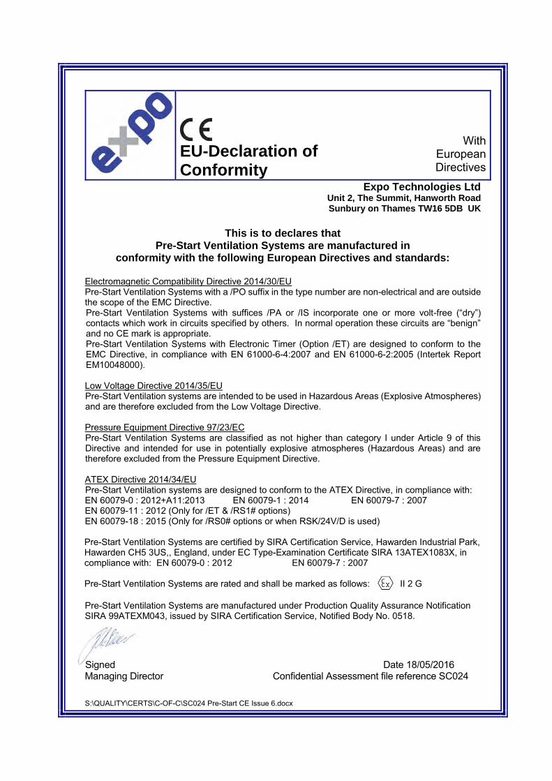
S:\QUALITY\CERTS\C-OF-C\SC024 Pre-Start CE Issue 6.docx
EU-Declaration of Conformity
With
European Directives
Expo Technologies Ltd Unit 2, The Summit, Hanworth Road Sunbury on Thames TW16 5DB UK
This is to declares that
Pre-Start Ventilation Systems are manufactured in conformity with the following European Directives and standards:
Electromagnetic Compatibility Directive 2014/30/EU Pre-Start Ventilation Systems with a /PO suffix in the type number are non-electrical and are outside the scope of the EMC Directive. Pre-Start Ventilation Systems with suffices /PA or /IS incorporate one or more volt-free (“dry”) contacts which work in circuits specified by others. In normal operation these circuits are “benign” and no CE mark is appropriate. Pre-Start Ventilation Systems with Electronic Timer (Option /ET) are designed to conform to the EMC Directive, in compliance with EN 61000-6-4:2007 and EN 61000-6-2:2005 (Intertek Report EM10048000). Low Voltage Directive 2014/35/EU Pre-Start Ventilation systems are intended to be used in Hazardous Areas (Explosive Atmospheres) and are therefore excluded from the Low Voltage Directive. Pressure Equipment Directive 97/23/EC Pre-Start Ventilation Systems are classified as not higher than category I under Article 9 of this Directive and intended for use in potentially explosive atmospheres (Hazardous Areas) and are therefore excluded from the Pressure Equipment Directive. ATEX Directive 2014/34/EU Pre-Start Ventilation systems are designed to conform to the ATEX Directive, in compliance with: EN 60079-0 : 2012+A11:2013 EN 60079-1 : 2014 EN 60079-7 : 2007 EN 60079-11 : 2012 (Only for /ET & /RS1# options) EN 60079-18 : 2015 (Only for /RS0# options or when RSK/24V/D is used) Pre-Start Ventilation Systems are certified by SIRA Certification Service, Hawarden Industrial Park, Hawarden CH5 3US,, England, under EC Type-Examination Certificate SIRA 13ATEX1083X, in compliance with: EN 60079-0 : 2012 EN 60079-7 : 2007 Pre-Start Ventilation Systems are rated and shall be marked as follows: II 2 G
Pre-Start Ventilation Systems are manufactured under Production Quality Assurance Notification SIRA 99ATEXM043, issued by SIRA Certification Service, Notified Body No. 0518.
Signed Date 18/05/2016 Managing Director Confidential Assessment file reference SC024 SiSS gned

On behalf of ExVeritas
Peter Lauritzen
Managing Director
This certificate may only be reproduced in its entirety and without any change, schedule included.
The status of this certificate can be verified at www.exveritas.com For help or assistance relating to this certificate, contact [email protected].
ExVeritas ApS, Severinsmindevej 6, 4420 Regstrup, Denmark. ExVeritas® is a registered trademark, unauthorised use will lead to prosecution.
Page 1 of 2 FO-CB-DK-37-1 V1
1 EU - Type Examination Certificate
2 Equipment intended for use in Potentially Explosive Atmospheres Directive 2014/34/EU
3 Certificate Number: ExVeritas 19ATEX0542X Issue: 1
4 Equipment: MiniPurge Interface Units MIUe
5 Manufacturer: Expo Technologies Ltd
6 Address: Unit 2, The Summit, Hanworth Road, Sunbury on Thames,
Surrey, TW16 5DB, UK
7 This equipment and any acceptable variation thereto are specified in the schedule to this certificate and the documents
therein referred to.
8 ExVeritas, Notified Body number 2804 in accordance with Article 17 of the Council Directive 2014/34/EU of 26 February
2014, certifies that this equipment or protective system has been found to comply with the Essential Health and Safety
Requirements relating to design and construction of equipment and protective systems for use in potentially explosive
atmospheres given in Annex II to the Directive
9 Compliance with the applicable Essential Health and Safety Requirements has been assured by compliance with the
following Standards and section 16 of this certificate:
EN IEC 60079-0: 2018 EN 60079-7: 2015+A1: 2018 EN 60079-31: 2014
10 If the sign “X” is placed after the certificate number, it indicates that the equipment is subject to special conditions for
safe use specified in the schedule to this certificate.
11 This EU-Type Examination Certificate relates only to the design, construction, examination and tests of the specified
equipment or protective system in accordance to the Directive 2014/34/EU. Further requirements of the Directive apply
to the manufacturing process and supply of this equipment or protective system. These are not covered by this certificate.
12 The marking of the equipment shall include the following:
II 2 G Ex eb IIC T5/4* Gb Tamb -20°C to +55/60* °C
II 2 D Ex tb IIIC T100°C Db Tamb -20°C to +55°C
Certificate: ExVeritas 19ATEX0542X Issue 1
This certificate may only be reproduced in its entirety and without any change, schedule included. For help or assistance relating to this certificate, contact [email protected].
ExVeritas ApS, Severinsmindevej 6, 4420 Regstrup, Denmark. ExVeritas® is a registered trademark, unauthorised use will lead to prosecution.
Page 2 of 2
FO-CB-DK-37-1 V1
13 Description of Equipment or Protective System
The Minipurge Interface Units are part of a series of IP66 rated enclosures that are used as Junction Boxes. The construction of
the boxes has been assessed under the component certificate ExV19ATEX0454U. A permitted content of the boxes is specified
on drawing SD7623. The current rating and maximum voltage for each terminal box is specified on the label and the general
assembly drawings. Three types of boxes have been covered by this certificate:
MIU/e1 – 7A, 400V, IP66 assembly drawing SD7851
MIU/e2 – 7A, 400V, IP66 assembly drawing SD7850
MIU/e1/MO – 2A, 400V, IP66 assembly drawing SD7861
13.1 Details of change:
The following changes are introduced in issue 1 of the certificate:
� Transfer of the certificate from ExVeritas UK, Notified Body number 2585 to ExVeritas Denmark, Notified Body number
2804. Certificate number remains unchanged.
14 Descriptive Documents
14.1 Associated Report and Certificate History:
Report Number Cert Issue Date Issue Comment R2328/A/1 17th Oct 2019 0 Initial issue of the Prime Certificate
EXV3094A 12th Jan 2021 1 Issue of the first variation, see section 13.1.
14.2 Compliance Drawings:
Issue 0
Title: Drawing No.: Rev. Level: Date: MIU/e Permitted Contents SD7623 2 02/10/19
MIU IECEX & ATEX Certificate label SD7624 4 02/10/19
MIU User Instructions SD7644 3 02/10/19
Minipurge Interface Unit SD7850 3 02/10/19
Minipurge Interface Unit SD7851 3 02/10/19
MIU with manual override SD7861 3 02/10/19
15 Conditions of Certification
15.1 Special Conditions for Safe Use
� Cable glands, breathers, drains and plugs shall be appropriately ATEX certified types, suitable for the cable and
conditions for use and installed in accordance with their manufacturers’ instructions. They shall maintain the IP66 rating
of the enclosure.
15.2 Conditions for Use (Routine tests)
� None
16 Essential Health and Safety Requirements
Essential Health and Safety Requirements are addressed by the standards listed in section 9 and where required the report listed
in section 14.1
The manufacturer shall inform the Notified Body of any modifications to the design of the product
described by this schedule.

IECEx Certificateof Conformity
Page 2 of 3
Issue No: 0
epresentative of production, was assessed and tested and found to comply with uality system, relating to the Ex products covered by this certificate, was tem requirements.This certificate is granted subject to the conditions as set out in nts as amended
d in the schedule of this certificate and the identified documents, was found
uipment - General requirements
quipment dust ignition protection by enclosure "t"
e compliance with safety and performance requirements essly included in the Standards listed above.
the examination and test requirements as recorded in:
IECEx Certificateof Conformity
INTERNATIONAL ELECTROTECHNICAL COMMISSIONIEC Certification System for Explosive Atmospheres
for rules and details of the IECEx Scheme visit www.iecex.com
Certificate No.: IECEx EXV 19.0057X
Status: Current
Date of Issue: 2019-11-12
Applicant: EXPO Technologies LimitedUnit 2, The Summit Hanworth Road Sunbury on Thames Surrey TW16 5DB United Kingdom
Equipment: Minipurge Interface Units MIUe
Optional accessory:
Type of Protection: Increased Safety Ex 'eb' Protection by Enclosure Ex 'tb'
Marking:
Page 1 of 3
Issue No: 0
Certificate history:
*Manual override (MO) models exempt
1.2.3.
Approved for issue on behalf of the IECEx Certification Body:
Position:
Signature:(for printed version)
Date:
This certificate and schedule may only be reproduced in full.This certificate is not transferable and remains the property of the issuing body.The Status and authenticity of this certificate may be verified by visiting www.iecex.com or use of this QR Code.
Certificate issued by:
ExVeritas LimitedUnits 16-18 Abenbury Way Wrexham Ind. Est. Wrexham LL 139UZ United Kingdom
Sean Clarke CEng MSc FIET
Certification Manager
Certificate No.: IECEx EXV 19.0057X
Date of issue: 2019-11-12
Manufacturer: EXPO Technologies LimitedUnit 2, The Summit Hanworth Road Sunbury on Thames Surrey TW16 5DB United Kingdom
Additional manufacturing locations:
This certificate is issued as verification that a sample(s), rthe IEC Standard list below and that the manufacturer's qassessed and found to comply with the IECEx Quality sysIECEx Scheme Rules, IECEx 02 and Operational Docume
STANDARDS :The equipment and any acceptable variations to it specifieto comply with the following standards
IEC 60079-0:2017 Edition:7.0
Explosive atmospheres - Part 0: Eq
IEC 60079-31:2013 Edition:2
Explosive atmospheres - Part 31: E
IEC 60079-7:2015 Edition:5.0
This Certificate does not indicatother than those expr
TEST & ASSESSMENT REPORTS:A sample(s) of the equipment listed has successfully met
Test Report:
Quality Assessment Report:
GB/EXV/ExTR19.0059/00
GB/SIR/QAR07.0012/15

e 0
8, Abenbury Way, Wrexham Industrial Estate, FO-CB-34 V1 am, United Kingdom LL13 9UZ.
Drawing No.: Rev Sheets Date: SD7623 2 1 of 1 02/10/19 SD7624 4 2 of 2 02/10/19 SD7644 3 3 of 3 02/10/19 SD7850 3 1 of 1 02/10/19 SD7851 3 1 of 1 02/10/19 SD7861 3 1 of 1 02/10/19
IECEx Certificateof Conformity
Certificate No.: IECEx EXV 19.0057X
Date of issue: 2019-11-12
Page 3 of 3
Issue No: 0
EQUIPMENT: Equipment and systems covered by this Certificate are as follows:
SPECIFIC CONDITIONS OF USE: YES as shown below:
Annex:
ExV 19.0057X IECEx Annex.pdf
The Minipurge Interface Units are part of a series of IP66 rated enclosures that are used as Junction Boxes. The construction of the boxes has been assessed under the component certificate IECEx EXV 19.0010U. A permitted content of the boxes is specified on drawing SD7623. The current rating and maximum voltage for each terminal box is specified on the label and the general assembly drawings. Three types of boxes have been covered by this certificate:
Cable glands, breathers, drains and plugs shall be appropriately IECEx certified types, suitable for the cable and conditions for use and
Annex to: IECEx EXV 19.0057X Issu
Page 1 of 1 ExVeritas, Units 16-1Wrexh
Manufacturer’s documents: Title: MIU/e Permitted Contents MIU IECEX & ATEX Certificate label MIU User Instructions Minipurge Interface Unit Minipurge Interface Unit MIU with manual override

HEDULE
n Certificate No. FM10ATEX0003X
RODUCED IN ITS ENTIRETY AND WITHOUT CHANGE
UK. SL4 1RS il: [email protected] www.fmapprovals.com
Page 2 of 3
ive System:
imer module. The Timer module is designed to be supplied k or an IS certified Power Supply. The battery pack contains
ith current limiting resistors. The timer settings are controlled ain part of the timer. Connections from the timer to a solenoid e solenoid is supplied as part of the timer circuit. Four LED’s mer circuit.
are designed to be installed within another enclosure. de ule powered by Expo Battery Pack ule powered by IS power supply
attery Pack mote Battery Pack ule powered by E.P.P.S.
nted nted imer surface
lying leads Value 1 to 9 digit 1, 2, 3 or 4
pply option are; .613 W (non linear) Ci = 363 nF Li = 0
option are; .46 W Ci = 363 nF Li = 0
n the ambient temperature;
Temperature Class
Group III
T101 °C
T100 °C
T85 °C
be used where UV light or radiation may impinge the Electronic Timer
nstalled within an enclosure which provides protection against impact. c providing a minimum IP20. rials shall not contain, by mass, more than 7.5% in total of magnesium,
re more than 10% in total of aluminium, magnesium, titanium andpecial precautions to avoid ignition hazard due to impact or friction.
ments:
en addressed by the standards listed in this certificate have been tial report identified in item 8.
Mick Gower Certification Manager, FM Approvals Ltd. Issue Date: 24th July 2017
THIS CERTIFICATE MAY ONLY BE REPRODUCED IN ITS ENTIRETY AND WITHOUT CHANGE
FM Approvals Ltd. 1 Windsor Dials, Windsor, Berkshire, UK. SL4 1RS T: +44 (0) 1753 750 000 F: +44 (0) 1753 868 700 E-mail: [email protected] www.fmapprovals.com
F ATEX 020 (Apr/16) Page 1 of 3
1 EU-TYPE EXAMINATION CERTIFICATE
2 Equipment or Protective systems intended for use in Potentially
Explosive Atmospheres - Directive 2014/34/EU
3 EU-Type Examination Certificate No: FM10ATEX0003X
4 Equipment or protective system:(Type Reference and Name)
Electronic Timer Module ETM-IS**-***
5 Name of Applicant:
Expo Technologies Ltd
6 Address of Applicant:
Unit 2, The Summit Hanworth Road Sunbury on Thames TW16 5DB
7 This equipment or protective system and any acceptable variation thereto is specified in the schedule to this certificate and documents therein referred to.
8 FM Approvals Ltd, notified body number 1725 in accordance with Article 17 of Directive 2014/34/EU of 26 February 2014, certifies that this equipment has been found to comply with the Essential Health and Safety Requirements relating to the design and construction of equipment intended for use in potentially explosive atmospheres given in Annex II to the Directive. The examination and test results are recorded in confidential report number:
3036907EC dated 12th November 2010
9 Compliance with the Essential Health and Safety Requirements, with the exception of those identified in item 15 of the schedule to this certificate, has been assessed by compliance with the following documents:
EN60079-0:2012+A11:2013, and EN 60079-11:2012
10 If the sign ‘X’ is placed after the certificate number, it indicates that the equipment is subject to specific conditions of use specified in the schedule to this certificate.
11 This EU-Type Examination certificate relates only to the design, examination and tests of the specified equipment or protective system in accordance to the directive 2014/34/EU. Further requirements of the Directive apply to the manufacturing process and supply of this equipment or protective system. These are not covered by this certificate.
12 The marking of the equipment or protective system shall include:
II 1 G Ex ia IIC T* Ga II 1 D Ex ia IIIC T* Da * See Description
���������� ��������� ������
��
�������������� ������ �����
��������
���!��!��$��$%'!%���;��<��<
SC
to EU-Type Examinatio
THIS CERTIFICATE MAY ONLY BE REP
FM Approvals Ltd. 1 Windsor Dials, Windsor, Berkshire, T: +44 (0) 1753 750 000 F: +44 (0) 1753 868 700 E-ma
F ATEX 020 (Apr/16)
13 Description of Equipment or Protect
The ETM-IS is a powered electronic tfrom either a self contained battery paca non-rechargeable battery together wby two BCD switches located on the mvalve and switch are also provided. Thare used to indicate the status of the ti The Timer module and Solenoid ValveElectronic Timer Module ETM-ISab-ca = sub module 1 = Timer Mod 2 = Timer mod 3 = Expo IS B 4 = Expo IS re 5 = Timer mod b = Mounting Style 1 = Plate mou 2 = Panel mouc = LED connection 1 = LED’s on T 2 = LED’s on fde = Maximum Time d = Reference e = Multiplying The input parameters for the power suUi = 11.1V Ii = 340 mA Pi = 2 The input parameters for the E.P.P.S. Ui = 10.8V Ii = 3.28 A Pi = 1 The temperature class is dependednt o
Ambinent Tamb = Group II
-20 °C to +60 °C T4
-20 °C to +59 °C T5
-20 °C to +44 °C T6
14 Specific Conditions of Use:
1. The Electronic Timer shall notSystem.
2. The Electronic Timer shall be i3. The Enclosure shall be metalli4. For light alloy enclosures, mate
titanium and zirconium. Whezirconium the user shall take s
15 Essential Health and Safety Require
The relevant EHSRs that have not beidentified and assessed in the confiden
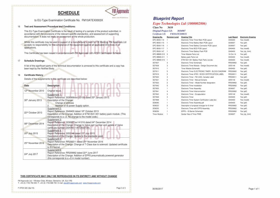
02806)
Last Report Electronic Drawing
er Main PCB Layout 3049400 Yes (msw8)
ttery Main PCB Layout 3036907 Yes (pdf)
ttery Connector PCB Layout 3036907 Yes (pdf)
D PCB Layout 3049400 Yes (msw8)
ttery Pack PCB 3049400 Yes (zip_html)
List 16-Oct-14 Yes (pdf)
ist 3049400 Yes (msw8)
ery Pack Parts List.doc 3049400 Yes (msw8)
hematic RR209962 Yes (pdf)
dule - Design Document.doc 3055146 Yes (msw8)
matic 3049400 Yes (pdf)
ECTRONIC TIMER - BLOCK DIAGRAM RR209962 Yes (pdf)
EX / IECEX CERTIFICATION LABEL RR206511 Yes (pdf)
M (USA, Canada) Label RR206511 Yes (pdf)
anual Extracts 3055146 Yes (msw8)
odel Number designation RR209962 Yes (pdf)
tallation RR209962 Yes (pdf)
sembly 3036907 Yes (pdf)
erconnection RR209962 Yes (pdf)
ncapsulation 3055146 Yes (msw8)
3049400 Yes (pdf)
stem Certification Label.doc 3049400 Yes (msw8)
sembly.pdf 3049400 Yes (pdf)
sal changes for E-timer RR209962 Yes (pdf)
h EPPS Assembly RR209962 Yes (pdf)
chematic RR209962 Yes (pdf)
r PWB 3036907 Yes (zip_html)
Page 1 of 1
SCHEDULE
to EU-Type Examination Certificate No. FM10ATEX0003X
THIS CERTIFICATE MAY ONLY BE REPRODUCED IN ITS ENTIRETY AND WITHOUT CHANGE
FM Approvals Ltd. 1 Windsor Dials, Windsor, Berkshire, UK. SL4 1RS T: +44 (0) 1753 750 000 F: +44 (0) 1753 868 700 E-mail: [email protected] www.fmapprovals.com
F ATEX 020 (Apr/16) Page 3 of 3
16 Test and Assessment Procedure and Conditions:
This EU-Type Examination Certificate is the result of testing of a sample of the product submitted, in accordance with the provisions of the relevant specific standard(s), and assessment of supporting documentation. It does not imply an assessment of the whole production. Whilst this certificate may be used in support of a manufacturer’s claim for CE Marking, FM Approvals Ltd accepts no responsibility for the compliance of the equipment against all applicable Directives in all applications. This Certificate has been issued in accordance with FM Approvals Ltd’s ATEX Certification Scheme.
17 Schedule Drawings
A list of the significant parts of the technical documentation is annexed to this certificate and a copy has been kept by the Notified Body.
18 Certificate History
Details of the supplements to this certificate are described below:
Date Description
12th November 2010 Original Issue.
30th January 2013
Supplement 1: Report Reference: 3036906rev130109 dated 25th January 2013. Description of the Change: 1. Change of address 2. Addition of IS power Supply option.
22nd October 2013
Supplement 2: Report Reference: 3049400 dated 18th October 2013 Description of the Change: Addition of ETM-IS31-001 battery pack module. (This corresponds to a =3. No change to the model code.)
08th December 2014
Supplement 3: Report Reference: 3036907rev141016 dated 04th December 2014 Description of the Change: Change to Valve part number and update of Valve certificate number (DEKRA 11ATEX0273X).
20th July 2015 Supplement 4: Report Reference: 3055146 dated 15th July 2015 Description of the Change: Update to the standards used.
25th November 2016
Supplement 5: Report Reference: RR206511 dated 23rd November 2016 Description of the Change: Change of T-Class due to solenoid. Updated certificate to EU format.
24th July 2017
Supplement 6: Report Reference: RR209962 dated 22nd June 2017 Description of the Change: Addition of EPPS pneumatically powered generator (this corresponds to a =5 in model number).
Blueprint ReportExpo Technologies Ltd (10000Class No 3610
Original Project I.D. 3036907
Certificate I.D. FM10ATEX0003X
Drawing No. Revision Level Drawing Title
EPC-B000-114 1 Electronic Timer Tim
EPC-B000-115 1 Electronic Timer Ba
EPC-B000-116 1 Electronic Timer Ba
EPC-B000-117 1 Electronic Timer BC
EPC-B000-147 1 Electronic Timer Ba
EPC-BBM0-010 3 Timer Module Parts
EPC-BBM0-011 1 Battery pack Parts L
EPC-BBM0-015 1 ETM-IS31-001 Batt
SD7607 3 Electronic Timer Sc
SD7608 3 Electronic Timer Mo
SD7610 1 Timer Module Sche
SD7611 5 Electronic Timer EL
SD7616 5 Electronic Timer AT
SD7620 4 Electronic Timer - F
SD7621 5 Electronic Timer - M
SD7622 2 Electronic Timer – M
SD7642 5 Electronic Timer Ins
SD7835 1 Electronic Timer As
SD7841 4 Electronic Timer Int
SD7842 3 Electronic Timer - E
SD7848 3 Electronic Timer
SD7898 1 Electronic Timer Sy
SD8085 1 Electronic Timer As
SD8222 2 Description of propo
SD8255 1 Electronic Timer wit
SD8256 1 EPPS – IS Barrier S
Timer Module 1 Gerber files of Time
30/06/2017


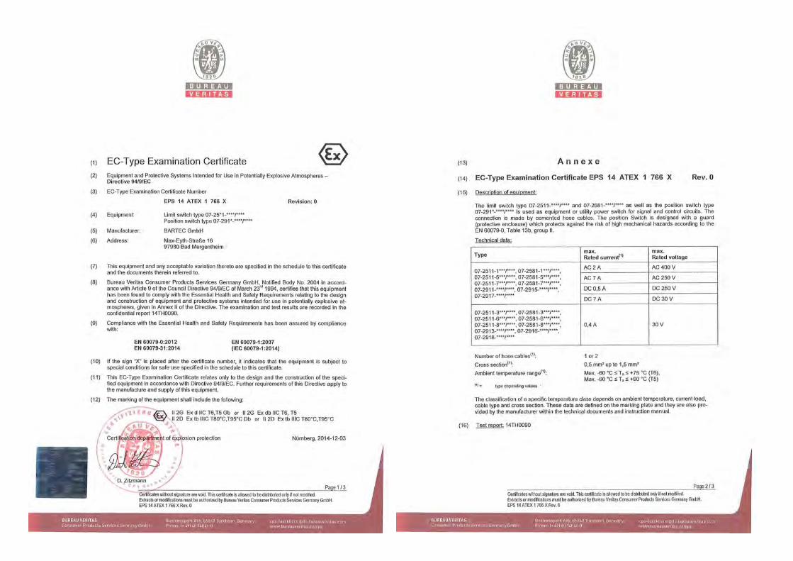
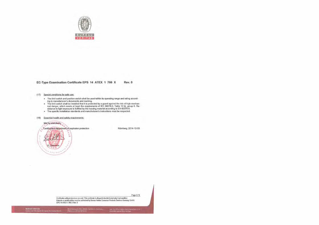


Expo Technologies USA
Expo Technologies Inc.9140 Ravenna Road Unit #3
Twinsburg,OH 440878, USA
T: +1 440 247 5314F: +1 330 487 0611
Expo Technologies UK
Expo Technologies Ltd.Unit 2 The Summit, Hanworth Road
Sunbury-On-Thames,TW16 5DB, UK
T: +44 20 8398 8011F: +44 20 8398 8014
Expo Technologies China
Qingdao Expo M. & E. Technologies Co. Ltd617 Shillin Er Road
Jimo District, Qingdao,266200 China
T: +86 532 8906 9858F: +86 532 8906 9858
www.expoworldwide.com