Embed Size (px)
Citation preview

Pre-scheduled Handoff for Service-aware and Seamless
Internet Access
Kun Xie1,2, Jiannong Cao3, Xin Wang2, Jigang Wen4
1 College of Computer Science and Electronics Engineering, Hunan University,Changsha, 410082, China
2 Department of Electrical and Computer Engineering, State University of New York atStony Brook, USA
3 Department of computing, The Hong Kong Polytechnic University, Hong Kong4 Institute of Computing Technology, Chinese Academy of Science, [email protected], [email protected], [email protected],
Abstract
Existing handoff techniques connect a user to a nearby access point wheneverit is available along the user’s moving path. If the path is not fully Wi-Ficovered, the user may suffer from frequent disconnections. In this work, wepropose a pre-scheduled handoff scheme, which determines a quality-awarepath so a mobile user can move across an Urban Wi-Fi Mesh network withuninterrupted Internet access at a required data rate. This scheme has sev-eral novel techniques. Firstly, by concurrently considering the received signalstrength at mobile users and the load of mesh routers (MRs), we design twopath finding metrics, contact weight and handoff count, according to the cov-erage information. Secondly, to measure the path metric in a practical meshnetwork with irregular and dynamic MR coverage, we propose a light-weightBloom-filter-based polling algorithm to discover the mobile stations (calledSTAs) covered in MR, and a Bloom-filter-based probabilistic algorithm toestimate the degree of coverage overlapping among MRs. Thirdly, based onthe path metrics, our proposed scheme supports flexible rate requirementsfrom mobile users through a fully distributed multi-service-class path findingalgorithm. Our pre-scheduled scheme considers both mobility and connec-tion requirement, so that the mobile user can continuously access the Internetwith the expected data rate. To our best knowledge, this is the first workto ensure seamless Internet access with rate consideration by finding a Wi-
Preprint submitted to Elsevier January 12, 2017

Fi covered geographic path in a practical wireless mesh network. We havecarried out extensive simulations, and the simulation results show that thepre-scheduled handoff scheme can provide appealing high data rate to mobileuser with minimum handoff delay.
Keywords: Seamless Internet Access, Handoff, Mobility Schedule.
1. INTRODUCTION
Wireless mesh networks (WMNs) have attracted significant attentions inrecent years as an avenue to provide cost-effective last-mile network accessand wireless Internet services to a large coverage area with a low infrastruc-ture cost [1, 2, 3]. Meanwhile, the bloom of the advanced wireless applicationsdrives the increasing requirements on providing high performance continuousInternet access for mobile users.
In a WMN, a user could access the MRs through a local area networksuch as 802.11 network, while MRs can communicate with each other throughthe backbone links such as WiMAX. Similar to wireless local area net-works (WLANs), mobile devices in WMNs may experience more frequenthandoffs than those in cellular networks because of the shorter transmis-sion range of mesh routers (MR), which makes the performance degradation(e.g.,interrupted connection, packet loss and delay) a more serious problem.To address problems associated with the handoff, many efforts have beenmade to improve the handoff process. The solutions include shorteningthe time of L2 channel scanning [4, 5, 6], optimizing Mobile IP for a bet-ter L3 handoff support [7, 8, 9], improving multi-hop routing to facilitatehandoff [10, 11, 12, 13, 14, 15, 16], and other methods from various aspect-s [17, 18, 19, 20, 21, 22, 23, 24, 25, 26]. These studies generally attemptto increase the Internet access in a best effort and opportunistic manner:providing a best connection whenever it is available along a given path.
However, these opportunistic solutions can hardly provide the mobileusers with continuous and high-performance Internet access in WMNs be-cause mobile users may suffer from frequent coverage loss or low qualityconnection. Based on the experimental studies on vehicular access of ex-isting WiFi networks in urban areas, the authors in [27] observe that themedian of the duration of an AP connection is about 13 seconds, while theaverage inter-arrival time for ”associable” APs is about 75 seconds, whichimplies the long period of disconnections. Several other experimental studies
2

[28, 29, 30] also demonstrate the connectivity intermittence is hardly avoid-able in current WiFi networks.
To provide mobile users with a better WiFi-covered path for Internetaccess, this paper studies a novel problem to guide a mobile user to walk alonga good Wi-Fi covered geographic path with well designed handoff strategy.Fig.1 shows a motivation example of our work. Assume a city area is coveredby a WMN with several MRs, and a user who is watching an online videoshowing the stock changes or attending a critical teleconference wants tomove from the location MR1 to MR4. If the mobile user moves along theshortest geographic path without good Wi-Fi coverage, he would be annoyedby the constant connection interruptions. Alternatively, the mobile user maychoose to move along the path MR1− > MR2− > MR3− > MR4 which isfully covered by Wi-Fi and provides him with high quality and continuousvideo services.
5
2
1
3
4
Figure 1: A motivation example.
Obviously, solving the above problem requires the concurrent considera-tion of geographic path finding and handoff strategy. The geographic pathis formed with physical road segments that a human user could walk along.This is totally different from an WMN routing whose goal is to search fora transmission path to deliver packets from the source to the destinationwithout considering the physical road condition, the wireless coverage, andthe stability of the connection in the remaining communication time. Themajor challenge we consider in this paper is to ensure the users to have the
3

Internet access through the MRs on the road over local area networks, notthe finding of backbone paths over wide-area links between MRs to transmitthe aggregate traffic.
To facilitate the finding of a Wi-Fi covered geographic path, we first definea coverage link by considering both the Wi-Fi coverage and the geographicreachability for the user, and then propose a quality-aware pre-scheduledhandoff scheme to determine a path that a mobile user can move across anUrban Wi-Fi Mesh network with uninterrupted Internet access at a requireddata rate with higher probability. Similar to the path finding service providedby the google map, our scheme provides an option for a user that needscontinuous Internet access and certain data rate to find a geographic paththat is well covered by the urban WMN. Our pre-scheduled handoff schemeincludes the following novel techniques.
First, we propose two novel metrics to facilitate the finding of a roadpath for a mobile user, contact weight and handoff count, according to thecoverage information about the WMNs. By taking into account both thepossible signal strength and the load of an MR in the metric design, theproposed metrics intend to provide an estimate on the quality of data servicethat a mobile user might experience when moving through the network.
Second, to calculate the contact weight metric in practical WMNs, wefirst propose a light-weight Bloom-filter-based polling algorithm to discoverthe STAs covered by an MR, and then propose a Bloom-filter-based proba-bilistic algorithm to estimate the degree of coverage overlapping among MRsto guide the movement of mobile users. Our proposed contact weight canreflect the strength of received signals and thus the data rate of the networkconnection. More importantly, our contact weight can be simply estimatedwithout assuming regular domain geometry and can better capture the cov-erage condition in a complex wireless environment. Our proposed schemeonly needs simple Bloom-filter messages to be exchanged among MRs.
Third, to find the path that better meets the quality expectation of amobile user and to design the strategy of mobility scheduling, we formulatethe path finding problem as a link-constrained path optimization problem toselect the path that minimizes the handoff frequency while considering therequired data rate. The minimization of the number of handoffs also helpsa user to find a path with shorter traveling distance under his performanceconstraints. Moreover, to provide users with flexible service support, wepropose a distributed multi-service-class path finding algorithm.
Finally, based on the knowledge of each next MR on the path, we propose
4

a cross-layer connection scheduling strategy, in which both the L2 and L3
handoffs are well pre-scheduled which largely reduces the handoff delay.We have carried out extensive simulations. The simulation results demon-
strate that our pre-scheduled handoff scheme can provide appealing high datarate to mobile users with the low handoff delay, which cannot be providedby any other existing work.
It is worth pointing out that the proposed pre-scheduled handoff schememay be implemented on mobile terminals to supplement the conventionalopportunistic handoff scheme [22, 4, 5, 6]. When moving in an area coveredby a WMN, a user can choose the handoff mode (pre-scheduled handoff oropportunistic handoff) based on the user’s application requirement. A usercan choose the pre-scheduled handoff to meet the requirements of criticalapplications and confirm the path when it is convenient. A mobile terminalequipped with multi-mode handoff schemes is similar to a vehicle equippedwith powerful GPS terminal, where a driver could decide if he would followthe GPS guidance based on his need.
The rest of this paper is organized as follows. The related work is present-ed in Section 2. The system model and problem description is presented inSection 3. The path finding metric is described in Section 4. The path findingalgorithm, the mobility scheduling strategy, and the connection schedulingstrategy are described in Section 6. We evaluate the performance of theproposed scheme through simulations in Section 7. Finally, we conclude thework in Section 9.
2. RELATED WORK
A complete handoff procedure in WMNs requires the mobility supportfrom both L2 and L3 [22]. The L2 handoff process in IEEE 802.11-basedwireless networks can be divided into three steps: scanning, authentication,and reassociation [6]. In L2 handoff, the delay is mainly resulted from thescanning process which is proportional to the number of channels scanned,and occupies the largest proportion of the entire L2 handoff delay (morethan 90 percent [31]). Extensive studies have been conducted to reduce oreliminate the channel scanning delay during the WMN handoff processes[4, 5, 6].
The L3 handoff process includes the IP address and routing path updates.As IEEE 802.11 WMNs do not provide sufficient mobility and handoff sup-port, a number of attempts have been made to enable the L3 handoff in
5

WMNs. MIPv4 and MIPv6 are the main mobility solutions at the L3 lay-er [7, 8]. Although MIP-based handoff schemes have good performance insupporting mobility related traffic delivery in the wired backhaul networks,the performance degrades in multi-hop WMNs. The authors in [9] proposea mobile agent(MA)-based handoff architecture for WMN, assuming eachmobile user has an MA residing on his registered mesh router to facilitatethe handoff signaling process. Besides above MIP and agent-based L3 hand-off approaches, several L3 approaches are proposed in WMNs to managenode address change [10, 11] and to modify the multi-hop routing protocolto facilitate the handoff [12, 13, 14, 15, 16].
Our pre-scheduled handoff scheme includes a cross-layer scheduling ofL2 and L3 connection setup to reduce both handoff delays. In contrast toexisting studies, in our scheme, a mobile user is able to make the handoffdecision in advance based on the knowledge of each next MR on the path.Therefore, the STA only needs to check one working channel of the nextMR and the scanning delay can be largely reduced. Moreover, with early L2
handoff event triggers, the handoff delay in L3 can also largely decrease bypreparing the L3 handoff in advance.
There are many other handoff solutions in WMNs. The work in [17] findsthat the rayleigh fading and teletraffic parameters play significant roles in e-valuating the handoff performance, based on which researchers can study theinteraction between physical link layer parameters and higher layer protocoldesigns. Some recent work in [23, 24] predicts the next AP to connect withand prepares for the handoff in advance to reduce the handoff delay. The workin [18] studies the evolutions of WMN handoff approaches for public safetyand disaster recovery networks. Yang et. al in [19] propose a joint handoffand energy management solution for WMNs, in which two distributed hand-off schemes are proposed for WMNs with adaptive transmission power andrate. Observing the large handoff delay as a result of the queueing delayand medium access delay at each MR due to the multi-hop transmissions ofsignaling messages for handoff, the authors in [20, 21] propose channel al-location and channel splitting strategies to reduce the channel access delay.Previous solutions on handoff management in infrastructure-based WMNsmainly assume there exist a single gateway in WMNs. Some recent studies[22, 32, 33] consider inter-gateway handoff and propose new architecturessuch as IMex [22] to facilitate the inter-gateway handoff management.
In summary, existing handoff solutions only consider the issue of connec-tion scheduling and attempt to maintain network connections in an oppor-
6

tunistic manner: providing a best connection whenever it is available along agiven path. There is little consideration on the throughput improvement andthe reduction of network disconnection as a result of terminal movement.
In contrast, this paper studies a novel problem with the goal of facilitatinga mobile user to find a Wi-Fi covered geographic path that provides seamlessInternet access while at the same time supporting a higher data rate. Inaddition, this paper concurrently considers the geographic path finding andhandoff and proposes a pre-scheduled handoff scheme in which both the mo-bility and the connection are well scheduled. To the best of our knowledge,this is the first work that proposes a pro-active and pre-scheduled handoffscheme to ensure higher-quality and seamless Internet access.
3. SYSTEM MODEL AND PROBLEM DESCRIPTION
3.1. System Model
We consider a widely accepted architecture for urban WMNs, which hastwo tiers as illustrated in Fig.2. The access tier connects the client wirelessdevices (e.g., a wireless laptop in a home, or handheld devices carried bya user on the move) to an MR. The backhaul tier interconnects the MRsto forward traffic to and from the wireline Internet entry points or gatewayMRs. Like imesh [34], in this paper, we use OLSR (Optimized Link StateRouting) as the routing protocol for backhaul network to route the packets.The term ”path” is used in this paper to indicate the path a user movesalong, while the term ”route” indicates the set of MRs along which packetswill be forwarded to reach the destination.
Internet
Gateway
MR
MR
MR
MR
MR
MR STA
Access link
Backhaul link
Figure 2: A two-tier WMN.
7

Each MR is equipped with two types of radio, a radio such as 802.11 toserve as an access point for local area network transmissions from mobileusers, and a radio such as WiMAX which has a larger capacity and range torelay the traffic in the backbone. Regardless of the actual radio techniquesused, access networks in a neighborhood will use orthogonal channels to avoidinterference.
Each MR has a limited local coverage area, which is determined by thetransmission range and the environment, and can serve only those STAsthat reside within its coverage area. A mobile user has to perform handoffto associate with another MR to obtain Internet access when it moves out ofthe coverage of its current MR and enters the coverage area of another MR.
In this work, any MR in the wireless network can serve as a coordinatorto facilitate its associated mobile users to find the optimal moving path. TheMR informs a user the path found based on which the mobility of the userand the connection with the network can be pre-scheduled. A user can walkalong the path given on the map towards his destination. If a user is willingto change the path, in case of the large rate change, he can be updated withthe information on the remaining path by an MR he associates with on theroad.
3.2. Problem Description
The problem of this paper: given the starting point and destination pointand the required data rate, find out a Wi-Fi covered path with the minimumhandoff frequency for the mobile user, so that it can obtain service-awareand seamless Internet access.
The main function of a navigation system is to find a feasible path basedon the map of the region of interest. In a general navigation system, differentmap features are extracted to generate a feasible path and instructions aboutthe surrounding to the user during the actual navigation process. To find afeasible Wi-Fi covered path in this paper, all the map-related data for pathfinding could be obtained as done in the conventional navigation systems.In order to take advantage of the proposed service to guide users to movealong the path, an MR and an STA can determine their positions throughlocalization hardware such as GPS.
In this paper, path, mobility and connection are well scheduled for themobile users to continuously obtain the required data rate. To facilitate auser to seamlessly access the Internet with a rate expectation, this paper
8

proposes an efficient fully distributed pre-scheduled handoff scheme by an-swering the following three questions:
1) How to define a path metric related to the quality of data service amobile user might experience?
2) How to design the mobility scheduling strategy and how can an MRdetermine an optimal Wi-Fi covered path for the associated mobile user?
3) What connection scheduling strategies and handoff procedures shouldbe adopted to schedule the mobile user on the path?
In the following sections, we will describe the key techniques in our pre-scheduled handoff scheme.
4. PATH FINDING METRIC
Our study focuses on the handoff scenario, where the major concern is thewireless coverage of the APs or MRs deployed. Our goal is to find a Wi-Ficovered geographic road path for a moving human user to walk towards hisdestination with well designed handoff strategy. Our problem is thus totallydifferent from a conventional routing problem whose goal is to search for aroute to deliver packets along links between routers.
We don’t consider backbone transmission links between routers, but in-stead introduce a virtual link, called coverage link, along with two metrics toreflect the quality of network access through an MR at the local area. Thecoverage link is defined by considering both the wireless coverage and theexistence of the road path between two MRs.
Although various routing metrics [35] are proposed in wireless mesh net-works to present the quality of a link connecting two routers, such as ETT,ETX [36], WCETT[37], MIC[38], CCM[39], CACU[40], and CMetric [41],they can not be directly applied to our handoff problem. These metrics donot consider the physical road conditions. Also, the quality of the virtuallink cannot be easily measured.
4.1. Coverage Link
Definition 1. A coverage link between two MRs (MRa and MRb) isdefined as the shortest feasible link that connectsMRa andMRb and satisfiesthe following two conditions.
• Condition 1 From the coverage perspectives, MRa and MRb areneighbors. An MR is called a neighbor of the reference MR if its cov-erage overlaps with that of the latter’s.
9

• Condition 2 From the geographic perspectives, a user can go fromMRa to MRb physically without obstacles on the road. According tothe map-related information, we can easily identify that whether thereexists a geographic route or not.
Therefore, a coverage link is defined by considering both the Wi-Fi cov-erage and the physical reach-ability for a moving user. A user moving alonga coverage link has a high probability of accessing the Internet without com-munication interruption. In the remaining of the paper, we simply call thecoverage link as a link, and we mainly care about the performance along thecoverage link. As far as we know, this paper is the first that introduces thenotions of coverage neighbor and coverage link and takes them into accountin the handoff schedule design.
Based on the coverage information, in this section, we introduce two per-formance metrics (Contact Weight and Handoff Count) to effectively capturethe quality of data service that a mobile user might experience when movingthrough the network.
4.2. Contact Weight
The data rate a mobile user can obtain is based on the strength of thereceived signal. Generally, according to the wireless channel fading model,the signal strength decreases if the transmission distance increases. A mobileuser that is far away from its associated MR and on the boundary of thecoverage area will have a lower rate.
MR1MR2
(a) light degree
MR1 MR2
(b) heavy degree
Figure 3: The degree of coverage overlapping.
As shown in Fig.3, the degree of coverage overlapping of two neighboringMRs (MRa and MRb) can reflect the strength of the received signal on thelink (a − b). If two adjacent MRs has a higher degree of coverage overlap-ping, it implies either the distance between these two MRs is smaller or thetransmission channel is good, and a mobile user moving along the link be-tween these two MRs can associate with an MR with a better signal during
10
the handoff to receive a higher average data rate with a higher probability.Although the channel condition of a link can vary over time, before a mo-bile is associated with a MR, there is no physical wireless link to measure.Therefore, we only estimate the signal strength based on the estimation ofthe coverage overlapping between two MRs.
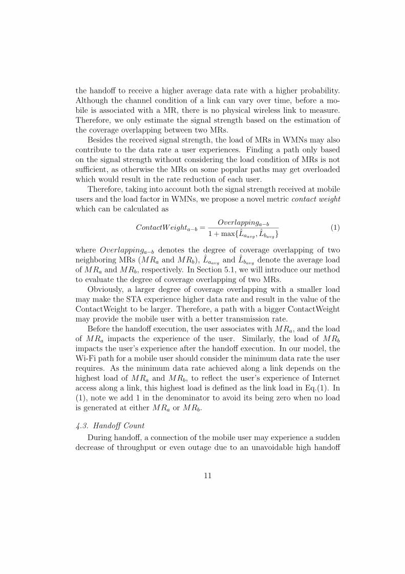
Besides the received signal strength, the load of MRs in WMNs may alsocontribute to the data rate a user experiences. Finding a path only basedon the signal strength without considering the load condition of MRs is notsufficient, as otherwise the MRs on some popular paths may get overloadedwhich would result in the rate reduction of each user.
Therefore, taking into account both the signal strength received at mobileusers and the load factor in WMNs, we propose a novel metric contact weightwhich can be calculated as
ContactWeighta−b =Overlappinga−b
1 + max{Laavg , Lbavg}(1)
where Overlappinga−b denotes the degree of coverage overlapping of twoneighboring MRs (MRa and MRb), Laavg and Lbavg denote the average loadof MRa and MRb, respectively. In Section 5.1, we will introduce our methodto evaluate the degree of coverage overlapping of two MRs.
Obviously, a larger degree of coverage overlapping with a smaller loadmay make the STA experience higher data rate and result in the value of theContactWeight to be larger. Therefore, a path with a bigger ContactWeightmay provide the mobile user with a better transmission rate.
Before the handoff execution, the user associates with MRa, and the loadof MRa impacts the experience of the user. Similarly, the load of MRb
impacts the user’s experience after the handoff execution. In our model, theWi-Fi path for a mobile user should consider the minimum data rate the userrequires. As the minimum data rate achieved along a link depends on thehighest load of MRa and MRb, to reflect the user’s experience of Internetaccess along a link, this highest load is defined as the link load in Eq.(1). In(1), note we add 1 in the denominator to avoid its being zero when no loadis generated at either MRa or MRb.
4.3. Handoff Count
During handoff, a connection of the mobile user may experience a suddendecrease of throughput or even outage due to an unavoidable high handoff
11

delay as a result of channel scanning, authentication and re-association pro-cedures. In addition, a handoff process may involve other message overheadto maintain the connection between an MR and its STAs. To minimize theperformance degradation and message overhead, an optimal path selectionscheme should minimize the handoff frequency on the path. Extending theconcept in [17], we define the handoff count as the number of handoff oper-ations along the moving path of a mobile user. As a handoff happens whena user changes its association from one MR to another MR with the twoforming a coverage link, the handoff count of a path is equal to the numberof links on the path and also the hop count of the backbone meshed network.
To better meet the user’s rate requirement, our algorithm will look for apath with good Wi-Fi coverage and light load. We will present our algorithmbased on the proposed metrics, contact weight and handoff count, in Section6. Our algorithm is also designed to achieve low handoff frequency.
5. Metric calculation
According to (1), given two adjacent MRs (MRa and MRb), to calculatethe contact weight of the link (a − b), we should first evaluate the degreeof coverage overlapping of these two MRs, and then the average load ofMRa and MRb. In this section, we present our method of calculating theserequired parameters.
5.1. Calculating the degree of coverage overlapping
In an urban WMNs, terrain, foliage, weather, obstacles, node movemen-t, and the presence of emitters of electromagnetic radiation all affect thetransmission range of MRs, so the coverage of an MR follows an irregulargeometric shape. We can not design a geometry-related solution to discovercoverage information by assuming that the wireless coverage area is con-tiguous and with a regular shape such as circular, sector, etc. Therefore,accurately discovering an MR’s coverage and evaluating how much the cov-erage is overlapped with that of a close-by MR are challenging. In this paper,we use a trick to estimate the coverage of an MR. More precisely, we use theset of STAs covered by an MR to denote the MR’s coverage.
Let Sa and Sb be the STA sets covered by MRa and MRb. The size of Sa
and Sb are denoted as na and nb respectively. The size of Sa ∪ Sb is denotedas na∪b. Therefore, the degree of coverage overlapping of this pair of MRs
12

can be calculated and normalized as follows.
Overlappinga−b =
{(na+nb−na∪b)
(na+nb)na + nb = 0
0 otherwise(2)
where Overlappinga−b is bounded between 0 and 1. Such a normalization canprovide a better estimate of the degree of coverage overlapping, and avoidthe bias when the number of STAs associated with an MR is too low or toohigh.
To calculate the degree of coverage overlapping of two adjacent MRs inpractical WMNs, we need to address the following key issues:
1) How does an MR discover its coverage and transmit the coverage in-formation to the MRs close-by?
2) How does the MR quantitatively estimate the degree of coverage over-lapping among MRs?
In the following subsection, we propose two algorithms to address theseissues.
5.1.1. Light-weight Bloom Filter Based Polling Algorithm
• Coverage Representation
T1T5
T2
T3
T4
T6
T7MR1
!1 2 3 4 5 6 7, , , , , ,STASet T T T T T T T
0 0 0 1 0 0 1 0 0 1 0 0 0 1 0 0 1 0 0 1 1 0 0 1 0 0 1 1 0 0 1 1
m=32
Coverage represented
by STA set
STA Set represented by
Bloom filter
Figure 4: MR coverage representation.
In wireless networks, the bandwidth is limited, especially when the net-work has a large number of users competing in channel access. To reduce thesignaling overhead, the coverage representation should be efficient.
A Bloom filter[42], which is known to be a space-efficient data structure,has a great potential for use in a distributed system to share informationabout available data. A Bloom filter uses an m-length string to representa data set with a size of n. To represent an element by a Bloom filter, theelement is hashed by k functions, and the corresponding bit from each hash
13

is set to 1 in the Bloom filter [42]. The source element cannot be discoveredfrom the Bloom filter and the privacy of the element is protected. Therefore,we apply Bloom filter to represent the coverage information and exchange thesimple Bloom filter strings among neighboring MRs. In the example shownin Fig.4, the size of the STA set is n = 7, the number of hash functions isk = 2, and the length of the Bloom filter string is m = 32.
• Coverage Discovery
Although an MR is aware of its associated set of STAs, it is hard forthe MR to find out the STAs that are also within its coverage area but arecurrently associated with other MRs and thus turn their radios to channelstaken by their individual associated MRs. Fig.5 illustrates the challenge ofthe coverage discovery problem. As an example, MRA needs to discover theSTA set comprising of T1, T2, T3, T4, T5, T6, T7. Although T6 and T7 are inthe coverage of MRA, they are associated with MRB and transmit packetsthrough Ch2. Thus these two STAs can hardly be discovered by MRA.
MRAMRB
T1T4
T2
T3
T6
T5T7
T9
T10
T8
Ch1
Ch2
Figure 5: Coverage discovery problem.
Under the standard Wi-Fi protocol, an STA can scan all channels to findthe best MR to associate with during its handoff. Requesting all STAs toscan different channels actively and send messages to each MR within thecoverage would consume a lot of bandwidth.
Alternatively, to get the statistics on the coverage condition, an MR canperiodically poll the channels of the close-by MRs, and an STA receiving thepolling with a good signal strength can return its ID. An MR could suspendits communications with the associated STAs using a NAV window. To avoidthe communication suspension, the MR can use another radio to send thepolling message and wait for the responses of the STAs. Although STAs mayrespond directly to the query of an MR, this again, could potentially lead tohigher overhead and consume lots of bandwidth.
14

Instead, we propose a light-weight Bloom-filter-based polling for MR todiscover the STAs associated with other MRs, as shown in Algorithm 1. Tosolve the coverage discovery problem as shown in Fig.5, when MRA wants tocollect the information on STAs which are covered by MRA but associatedwith MRB, it will send out a query message on the working channel Ch2 ofthe neighbor MRB to learn the number of STAs, as shown in Fig.6(a).
The channels of neighboring MRs are generally orthogonal to avoid in-terference. If the channel can change over time, the change at an MR will beannounced to its neighbors. The polling can be done when there is a needto look for the path and there is a time duration from the last update ofthe STA knowledge. It will not be performed frequently. This needs a smallprotocol support at the MAC layer along with the association part for usersto respond. To avoid interfering with existing transmissions, a request canbe first sent to the neighboring MR, which will reserve a time duration usingNAV window for the querying MR.
Along the polling message, the MRA also sends out a schedule with mslots for responses where m is the length of the Bloom filter, and initializesthe Bloom filter SBFCh2 to zero. To apply the Bloom filter to representan STA set in the coverage of an MR, we let STAs to fill the Bloom filterintelligently through the analog tone transmission in successive m time slots.The STA transmissions in a sequence of slots can be similar done by a TDMAkind of procedure in general. An STA receiving the query selects the timeslots for responding based on the hash results of its ID, as shown in Fig.6(b)in the paper. The STA will broadcast a simple tone signal during the timeslot l if one of the hash values hp[ID](1 ≤ p ≤ k) is l. MRA sets thebit of SBFCh2 to one if it receives the tone signal in a corresponding slot.The slot level synchronization has been considered in current 802.11. Thequery messages will further facilitate different STAs to coordinate in sendingresponses in different slots. The implementation of polling and response issimple. Compared to complete message feedbacks from each covered STA,the simple beacons have much lower signaling overhead.
A Bloom filter is a bit string often utilized to represent a data set. Thelength of bloom filter, m, is usually determined by the number of elements inthe data set to control the probability of bit setting as a result of the hashingoperation. From literature studies, a Bloom filter can best represent a dataset when the probability of bit setting is 0.5. To apply the Bloom filter torepresent an STA set in the coverage of an MR, we can first estimate the sizeof STA set based on the past traffic and then determine the m accordingly.
15

Figure 6: Bloom filter based polling for STA discovery.
The complete procedure for an MRA to discover its covered STA set canbe described in Algorithm 1. The MRA first takes a Bloom filter stringSBFA to represent the STAs associated with it. It then polls the otherMRs’ working channels one by one exploiting use of the light-weight Bloomfilter. During the query process, the STAs located in its coverage area butassociated with other MRs can be discovered and the STAs working on thechannel ch(j) are represented by SBFch(j).
From [42], we know that the union of two sets can be directly representedby employing the OR operation on the Bloom filter strings that respectivelyrepresent the two sets. Therefore, MRA can merge SBFA with all the otherSBFch(j) through the ”OR” operation to form the SBFA to represent allSTAs in its coverage area.
From Fig.6, the MR will spend a time period of 1/2RTT +mTslot to dis-cover the number of STAs associated with a neighboring MR. To obtain thecoverage information in a dynamic wireless environment, MR can executethe light-weight Bloom-filter-based polling algorithm periodically. Becausethe algorithm is designed based on Bloom filter, the time and message over-heads of our coverage discovery procedure are very low, which makes it lightweight and easy to implement over the off-the-shelf WiFi products, followingthe signal diagram in Fig.6.
To calculate the ContactWeighta−b of linka−b based on Eq(2), after anMR obtains SBFa and SBFb corresponding to MRa and MRb, it needs tofind the sizes of the STA set of MRa, MRb, and their union set, which aredenoted as na, nb, and na∪b respectively. In the next subsection, we proposea probabilistic algorithm to estimate the size of STA set based on the bitstrings of Bloom filter exchanged among MRs.
16

Algorithm 1 Bloom filter based polling algorithmInput: MRA and its neighboring MRs.Output: SBFA which represents all the STAs covered by MRA.
Part 1: Represent the STAs associated with MRA
1: for each STAi associated with MRA do2: The k hash functions are applied to STAi
′s ID(i) to compute the correspondingk locations of the SBFA, and the corresponding k bits are all set to 1.That is, for1 ≤ y ≤ k, let SBFA[hy(ID(i))] = 1.
3: end forPart 2:Represent the STAs associated with other neighboring MRs
4: for each MRj in the neighborhood of MRA, and its working channel is ch(j) do5: MRA sends out a poll(ch(j)) message and a schedule with m time slots for response6: An STA receiving the poll locally hashes its ID by using the k hash functions, and
broadcasts a simple signal tone during the time slot l hashed by its ID.7: MRA sets the bit of SBFch(j)[l] to 1 if it receives the tone signal in time slot l.8: end for
Part 3: Merge Bloom filters9: SBFA = SBFA ∪
∪ch(j) of all neighbor MRj
SBFch(j)
5.1.2. Bloom Filter Based Probabilistic Algorithm
From Algorithm 1, SBF represents STA sets by utilizing k hash functionsto set the k bits of SBF to 1. Even though some STAs may share thesame bits, the number of bits set to 1 in the Bloom filter with the increaseof the number of STAs. Therefore, we propose a probabilistic algorithm toestimate the size of STA set as shown in Theorem 1 by utilizing the occupancyinformation of the Bloom filter.
Theorem 1 Suppose SBFS1 represent the STA set S1 of MR1 usinga Bloom filter of length m and k hash functions, and the number of bit-s set to 1 in the SBFS1 is s. Then the number of STAs in S1 is n =log
(1− s
m
)/(k × log
(1− 1
m
)).
Proof. We assume that there are totally n STAs in S1. After beinghashed into the SBFS1 , the probability that a specific bit is still 0 is p(n) =(1− 1
m
)kn ≈ e−kn/m. The probability that a specific bit is set to 1 can beexpressed as 1 − p. After representing n STAs, the total expected number
of bits set to 1 is S (n) = (1− p) × m =(1− (1− 1/m)kn
)× m. And we
17

further have
S (n) = (1− p)×m =(1− (1− 1/m)kn
)×m
⇒ 1− (1− 1/m)kn = S (n) /m
⇒ n = log(1− S (n) /m
)/ (k log ((1− 1/m)))
(3)
Let s = S (n), the proof completes. �Thus, to calculate the degree of coverage overlapping of a pair of MRs as
shown in Eq(2), we first employ the OR operation on the Bloom filters toestimate the cardinality of the set union. Then, we can use the estimated setsizes of |S1|, |S2|, and |S1 ∪ S2| to obtain the degree of coverage overlapping
of |S1|+|S2|−|S1∪S2||S1|+|S2| , where |S1|+ |S2| − |S1 ∪ S2| = |S1 ∩ S2|.
The cost on calculating the degree of coverage overlapping is low. Given aBloom filter, to estimate the size of STA set represented by the Bloom filter,the cost for counting the number of ”1” in a Bloom filter of length m is O(m).Also, our proposed probabilistic estimation is performed based on simplebinary operations of Bloom filter strings, which can be easily implementedon well-designed hardware at the low complexity.
Following we will analyze the accuracy of our proposed probabilistic es-timation algorithm. The error margins can be calculated for given intervalsof set sizes following Theorem 3.
Theorem 2 Suppose SBFS1 represent the STA set of MR1, which isdenoted as S1 and includes n STAs. SBFS1 is a Bloom-filter of length m,which is formed with k hash functions. After representing n STAs, the ex-pected number of bits that are set to 1 in SBFS1 is denoted by S (n). Thenthe probability for the number of ”1” bits to be more than (1 + δ) S (n)
is p(TotalBit > (1 + δ) S (n)
)≤ e−S(n)δ2/3, (0 < δ < 1). The probabil-
ity of number of bits which are set to 1 to be less than (1− δ) S (n) is
p(TotalBit < (1− δ) S (n)
)≤ e−S(n)δ2/2, (0 < δ < 1).
Proof. We assume that n STAs are hashed into the SBF. The prob-ability that t bits are set to 1 is a binomial random variable, and can beexpressed as p (TotalBit = t|n) = Ct
m
((1− p (n))tp(n)m−t) . Using Chernoff
bound [43], we can obtain the upper bound and lower bound of the prob-
abilities, that is, p(TotalBit > (1 + δ) S (n)
)≤ e−S(n)δ2/3, 0 < δ < 1 and
p(TotalBit < (1− δ) S (n)
)≤ e−S(n)δ2/2, 0 < δ < 1. The proof completes.
�
18

Theorem 3 Suppose a Bloom filter SBFS1 represent STA set S1 of MR1
with the filter length m and k hash functions, and the number of bits setto 1 is s. For any nl and nu, the number of STAs hashed into SBFS1 isdenoted by n and lies in the range (nl, nu) with a probability of at least
1− e−S(nu)δ2u/2 − e−S(nl)δ2l /3, where (1 + δl) S (nl) < s and (1− δu) S (nu) > s.
Proof. We prove the theorem in the following two steps.If the number of STAs n ≤ nl, then we have p (TotalBit ≥ s|n) ≤
p (TotalBit ≥ s|nl) =m∑t=s
(Ct
m
((1− p (n))tp(n)m−t)), which shows that the
probability of p (TotalBit ≥ s|n) decreases when s increases. We choosenl and δl which make (1 + δl) S (nl) < s. Following Theorem 2, we ob-
tain p (TotalBit ≥ s|nl) < p(TotalBit > (1 + δl) S (nl) |nl
)≤ e−S(nl)δ
2l /3.
Therefore, we can obtain p (TotalBit ≥ s|n) < e−S(nl)δ2l /3.
If n ≥ nu, we can obtain p (TotalBit ≤ s|n) ≤ p (TotalBit ≤ s|nu) =
1−m∑t=s
(Ct
m
((1− p (n))tp(n)m−t)), which shows p (TotalBit < s |n) increases
as s increases. Similarly to the above proof for (n ≤ nl), we choose nu and δuto make (1− δu) S (nu) > s, and we can obtain that p (TotalBit ≤ s|nu) <
p(TotalBit < (1− δu) S (nu) |nu
)≤ e−S(nu)δ2u/2.
Therefore, we obtain p (TotalBit ≤ s|n) < e−S(nu)δ2u/2.Combining (n ≤ nl) and (n ≥ nu), we can conclude that the number of
STAs (denoted by n) hashed into the SBFS1 lies in the range (nl, nu) with a
probability of at least 1− e−S(nu)δ2u/2 − e−S(nl)δ2l /3. The proof completes. �
5.2. Calculating the average load of an MR
In a WMN, the load of an MR is not only impacted by the users it serves,but also the load incurred for it to forward the traffic for other MRs in thebackhaul network. However, as introduced in the system model in Section3, the traffic from MRs is relayed with the radio of large capacity and rangesuch as WiMAX in the backhaul network. In this work, we focus on thehandoff in local area networks, and assume that the backhaul network hasenough bandwidth. Therefore, to determine the load impact on the MNs’rate, we only consider the traffic transmitted using the local-area networkresources.
We define the load La of MRa to be the total load generated by all usersassociated with MRa, expressed as La =
∑u∈Ua
(tu), where Ua denotes the
19

STA set associated with MRa and tu represents the rate of the total datatransmitted to and from the mobile user u. To obtain the load La, an MRcan track the total traffic generated by its associated users.
User data traffic is often bursty which makes the load on the MRs dy-namic. To better estimate the load of an MR, we take EWMA (exponentiallyweighted moving average) to calculate the average load:
Laavg = (1− α) Laavg + αLa (4)
where α is the weight in EWMA.The average load of an MR will be applied to facilitate the path finding
of a user and balance the network load. Each MR periodically calculatesand updates the average load by using (4). If the load change of an MRexceeds certain level, the MR will broadcast the updated load with a smallTTL through the backhaul mesh link to its neighboring nodes. If the loadof an MR changes dramatically and cannot serve a mobile user at the user’sexpected data rate, the mobile user can inform its current associated MR toinitiate an new path search to avoid large performance degradation.
6. PATH FINDING ALGORITHM AND MOBILITY SCHEDUL-ING
6.1. Path Finding Problem Formulation
The aim of our work is to facilitate a mobile user to find a moving paththat allows for seamless Internet access while supporting higher transmissionquality. A user may inform his closest MR the required data rate accordingto the desired application quality. MR will return a path that satisfies therate requirement. For example, a streaming application generally has somerate expectation. On the other hand, streaming sources normally supportgraceful rate adaptation which is very useful when the allowable transmissionbandwidth changes.
Instead of meeting the rate requirement of each user, for the simplicity ofsystem implementation, we consider supporting CoS (class of services) map-ping between the available data rate and the quality-level for transmission.Specifically, if an application with the desired quality level Ai requires thedata rate to be larger than Oi, this requirement can be mapped to a serviceclass Ci, as expressed in (5).
Ai → Ci → Oi, (5)
20

where Oi is the minimum data rate of the service class Ci. Based on theCoS mapping, an MR can construct a path table with different paths corre-sponding to different CoS classes. A mobile user will select the path whichsatisfies the rate requirement according to application’s quality expectationof this user.
Based on the proposed path finding metrics including the contact weightand the handoff count of path, the path finding problem can be formulatedas a link-constrained path optimization problem, expressed as
Minimize handoff count (path(s, d)Ci , path(s, d)Ci ∈ P (s, d))s.t. ContactWeight(link(x, z)Ci) > wthi
∀x, zlink(x, z)Ci ∈ path(s, d)Ci
(6)
where s and d denote the beginning MR and end MR that cover the startingpoint and destination point of the mobile user, P (s, d) is the set of availableWi-Fi covered paths. path(s, d)Ci is a path from s to d belonging to theclass Ci. wthi
is the minimum contact weight requirement of class Ci. wthi
can be determined based on Oi corresponding to the class Ci. In practice,we can use statistics results from experiments as a reference to determinethe required contact weight for a given data rate requirement. In Section 7,we will show a way to utilize cumulative distribution function (CDF) as thestatistic tool to obtain the relationship of the value of contact weight anddata rate, based on which, the wth is set according to the user’s requirement.
The handoff count on a path depends on the number of links on the path.Thus, the path finding problem is to find a path with the minimum numberof links with each link satisfying the user’s rate requirement. Therefore, thepath found may not be long and the mobile user may prefer to move on.
6.2. Problem Transformation
The link constraint ContactWeight(link(x, z)Ci) > wthiconsiderably
complicates the problem in (6), which makes it difficult to directly solvethe problem. To simplify the problem and look for the solution, we updatethe link cost of link(x, z)Ci according to different class’s rate requirement asfollows:
Linkcost(link(x, z)
Ci
)=
{1 ContactWeight
(link(x, z)
Ci
)≥ wthi
+∞ otherwise(7)
where the cost Linkcost(link(x, z)Ci
)between two MRs x and z is set to 1
if the link’s contact weight is not less than the contact weight threshold wthi;
21

otherwise, it is set to +∞. By updating the link cost in (7), the problemin (6) can be translated to the one of finding a path with the minimumaccumulated cost of all links as
Minimize path cos t(path(s, d)Ci , path(s, d)Ci ∈ P (s, d))
s.t. path cos t(s, d)Ci =∑
link(x,z)Ci∈path(s,d)Ci
Linkcost(link(x, z)Ci
)(8)
6.3. Multi-Service-Class Path Finding Algorithm
To find a well Wi-Fi covered path to provide user with seamless and highperformance communications and Internet access, the path finding algorithmshould meet the following requirements: 1) To flexibly support requirementsfrom different mobile users, the path finding algorithm should be able to findmultiple well covered Wi-Fi paths for multiple service classes. 2) In a wirelessnetwork, sometimes it may not be possible to guarantee a rate absolutely. Auser may choose to accept the highest available rate when his desired ratecannot be ensured. The path finding algorithm should find an alternate pathfor the user to seamlessly access the Internet at a lower quality level.
According to the requirements, we propose a Multi-Service-Class PathFinding algorithm (MSCPF) to support diverse quality requirements frommobile users, as shown in Algorithm 2. MSCPF can be distributively exe-cuted and includes two parts as follows.
In part one, an MR constructs its path table for different service classes.Firstly, each MR calculates the cost of its outgoing coverage links by using(1). Secondly, MR updates the link cost according to different class’s raterequirement in (7). Finally, the distributed Bellman-Ford shortest path al-gorithm [44] is implemented at each MR using these newly updated costs.Each MRk (k ∈ 1, ..., N) updates its cost towards the destination as
PCik = min
j∈N(k)
(link cos t(link(k, j)Ci) + PCi
j
)(9)
where PCik denotes the cost from node k to the destination, N(k) denotes
the set of neighboring nodes of MRk, and link cos t(link(k, j)Ci) denotes theupdated cost between node k and node j calculated in Step 3.
In part two, the mobile user informs its closest MR the required qualitylevel, and the MR will determine the class Ci accordingly. If MSCPF algo-rithm cannot find a path that meets the user’s required quality, to make thepath finding process more robust, MSCPF can provide the user an alternatepath corresponding to a lower class of service at a lower expected rate.
22

The worst-case computational complexity of calculating the costs at eachnode in path calculation step is O(N2) since it requires two nested loops, andeach has a maximum length of N − 1 to calculate all the nodes.
Algorithm 2 Multi-Service-Class Path Finding algorithm (MSCPF)Part one: QoS Path construction
1. Link cost calculation:Each MRx (x ∈ 1, ..., N) calculates the degree of coverageoverlapping oxz of its outgoing link (x, z) by using (2) and the average load onthe MRx (denoted as Lx)by using (4) where z ∈ N(x) and N(x) denotes theset of neighboring nodes of MRx. After MRx obtains Lx, it exchanges the loadinformation with its neighboring nodes. The cost of the (x, z)-th link is calculatedas ContactWeight(link(x, z)) = oxz
1+max{Lx,Lz}by using (1).
2. Update the link cost: Let link cos t(link(x, z)Ci) denote the updated cost of link(x, z) for class Ci, and wthi be the contact weight threshold of this class. After wehave ContactWeight(link(x, z)Ci), the updated cost link cos t(link(x, z)Ci) can beobtained according to (7).
3. CoS Path calculation: Apply distributed Bellman-Ford algorithm to build thepath table with different paths corresponding to different classes based on theupdated link costs. Each MRk (k ∈ 1, ..., N) executes the iteration PCi
k =
minj∈N(k)(link cos t(link(k, j)Ci) + PCi
j ), where N(k) denotes the set of neighbor-
ing nodes of MRk, PCij represents the latest estimate of the minimum accumulated
cost of the Ci-class-path from MRj to the destination, and link cos t(link(k, j)Ci)is the updated cost from MRk to MRj calculated in Step 2.
Part two: Path selection
1. CoS class identification: The closest MR determines the class Ci according tothe quality requirement of the user.
2. Path finding: MR looks for the path table and checks if there exist one path forthis class Ci. If yes, return this path; otherwise go to Step 3.
3. Update the CoS class: If Ci is the lowest level class supported, return ”No path”;otherwise Ci = Ci−1 and go to Step 2.
6.4. Mobility and Connection Scheduling Strategies
When a user needs to move from a starting point to a destination point,the user first informs the MR closest about his quality requirement. Afterrunning the MSCPF algorithm, the MR informs the user the path foundbased on which the mobility of the user and the connection with the networkcan be pre-scheduled. After selecting the Wi-Fi covered path for a mobile
23

user, the moving direction of the user is scheduled according to the directionof the sequence of links on the path.
To achieve a small handoff delay and packet loss, we concurrently considerL2 and L3 handoffs with the support of a well-scheduled handoff strategy. Inour design, with the knowledge of the links thus each next MR in advance, theconnection schedule for each link can be implemented in a simple way. Whenmoving from MRA to MRB, an STA only needs to check the signal strengthof the channel of MRB when the signal received from the MRA is not good,and the handoff is triggered and the association is changed from MRA toMRB when the signal strength from MRB is higher than a threshold. Inour mechanism, an STA knows its next MR, MRB, in advance. It thus onlyneeds to check the working channel of MRB, which helps to significantlyreduce the scanning delay of L2. We call such a connection strategy in thispaper a scheduled channel check.
With our pre-scheduled handoff, the L2 scanning delay is significantlyreduced and a handoff is triggered at L2 when the signal strength experiencesa significant change between two MRs. We also use the signal strengthchange to trigger the L3 handoff. When the signal strength indicator, whichalso functions as the L3 handoff trigger, exceeds a certain threshold, the L2
handoff will be triggered, and consequently an L3 handoff will be triggered.The cross-layer design by using L2 information benefits the overall handoffperformance.
7. SIMULATION
7.1. Simulation Setup
We implement our pre-scheduled handoff scheme by using the simulatorNCTUns [45]. Our channel follows the Rayleigh fading model. The maxi-mum transmission range of the access radio and the backhaul radio of eachMR are set to 250 meters and 500 meters respectively. The access radios ofthe close-by MRs are tuned to orthogonal channels. All the MRs connectto a gateway through wireless backhaul links, and the gateway connects toan external server through a wired connection. As described in the systemmodel in Section 3, in urban WMNs, we can use the radio with large capac-ity and range such as WiMAX to form the backhaul network. We assumethat the backhaul network between an MR and the gateway and the wiredlink between the gateway and the external server can always provide enough
24

bandwidth for all the traffic, whereas the wireless access network is the bot-tleneck in terms of the data rate. A mobile node (MN) receives packetsonly from the MR it is associated with. The received data rate is used as aperformance metric to evaluate different handoff schemes and measured atthe MN. In all simulations, we use UDP traffic instead of the TCP trafficto decouple the transmission behavior from the effect of congestion control.To evaluate the impact of various factors on the rate of an MN, we let theserver transmit data at the maximum transmission rate allowed by the cur-rent wireless medium. To achieve this, we set the traffic mode of the serverto be ”ttcp” in NCTUns. Under this mode, the external server can transmitUDP packets to the MN as fast as it can. For all the other STAs associatedwith MRs, however, we configure their traffic mode to be ”stg” instead of”ttcp”. The stg mode would ensure the external server to transmit UDPpackets to an STA at a constant transmission rate, which would allow us tobetter control the background traffic load. To vary the total traffic load ofan MR, we change the packet length thus the data rate from the server toeach STA. The simulation includes two parts.
Part 1: Data collecting and training. In this part, we examine howthe degree of coverage overlapping, the load of MRs, and handoff strate-gy impact the received rate of MN in a linear network. We vary networkconditions to get different contact weights, and obtain simulation results ofdifferent data rates under various contact weights. Then, according to theprobability theory and statistics, we build the benchmark which describesthe relationship of data rate and the value of contact weight.
Part 2: Guiding user movement with the training data. Weperform simulations with MRs randomly deployed in an area of 4000 m ×4000 m. We use the benchmark built in the first part as the base to guidethe mobile user movement in the network to obtain its desired rate.
7.2. Simulation Results (Part 1)
In this part, we carry out the simulations in a linear network to obtain alarge number of simulation results to train the benchmark. In the linear net-work, some MRs are deployed along a line of 2000 m with the same distancebetween MRs, and these MRs connect with the gateway over one or a fewhops. In the linear network, the STAs are uniformly distributed in the net-work. By changing the location of MRs and the STA density, we can changethe value of the degree of coverage overlapping of each pair of neighboring
25

MRs and the total load generated by STAs, and thus change the value ofweight contact.
0 500 1000 1500 2000
0
100
200
300
400
500
600
700
800
900
Rec
ieve
rate
(KB/
Sec)
Distance from the starting point(m)
degree=0.094
(a)
0 500 1000 1500 20000
100
200
300
400
500
600
700
800
Rec
ieve
rate
(KB/
Sec)
Distance from the starting point(m)
degree=0.142
(b)
0 500 1000 1500 2000
300
400
500
600
700
800
Rec
ieve
rate
(KB/
Sec)
Distance from the starting point(m)
degree=0.196
(c)
0 500 1000 1500 2000
400
450
500
550
600
650
700
750
800
Rec
ieve
rate
(KB/
Sec)
Distance from the starting point(m)
degree=0.252
(d)
0 500 1000 1500 2000560580600620640660680700720740760
Rec
ieve
rate
(KB/
Sec)
Distance from the starting point(m)
degree=0.312
(e)
0 500 1000 1500 2000620
640
660
680
700
720
740
760
Rec
ieve
rate
(KB/
Sec)
Distance from the starting point(m)
degree=0.37
(f)
Figure 7: Received rate at MN with different degree of coverage overlapping.
7.2.1. Impact of Coverage Overlapping
We change the location of MRs in the linear network while keeping theload of MR (by fixing the number of STAs associated with the MR and alsofixing the load generated by each STA) to be the same to investigate how thedegree of coverage overlapping affects the mobile user’s received rate. Fig.7shows the received rate at the mobile user under our pre-scheduled handoffscheme with different degree of coverage overlapping whose values increasefrom Fig.7(a) to Fig.7(f). As this simulation is done in a linear network of2000 m, the maximum distance from the starting point of the x-axis is 2000m. Note the y-axis ranges in different Figure (7(a))-(7(f)) are different. Forexample, when the degree equals to 0.094 in Fig. 7(a), the data rate is within[0, 750], while in Fig. 7(f), the data rate is within [620, 750]. It is clearlyshown that the mobile user moving along the path with a larger overlappingdegree obtains a larger minimum received rate. In Fig.7, we observe thatthe received rate changes periodically and degrades in the middle of the pathbetween two MRs. This is mainly because the strength of the received signalbecomes weak when the mobile user is in the central area of the link and
26

thus farther away from the MRs. Also, the received rate reduces as a resultof the handoff.
7.2.2. Impact of MR’s Load
To investigate how MR’s load affects the received rate, we vary the MRload by changing the data rate of the STAs associated with the MR whilekeeping the coverage overlapping at the same degree. We have evaluatedthe performance by varying MR’s load under different degree of coverageoverlapping, and due to the page limit, we only show results for degree d =0.252 in Fig.8. All STAs associating with the same MR share and competeto access the wireless media. The actual rate of an individual mobile userdepends on how the wireless channel capacity is allocated[46]. From Fig.8,we can see the higher the MR’s average load is (average rate measured atMR before MN’s association in Fig.8 ), the lower the received rate the mobilenode can obtain.
scenario
1
scenario
2
scenario
3
scenario
4
scenario
5
scenario
6
scenario
7
scenario
8
scenario
9
scenario
10
scenario
11
scenario
12
scenario
130
100
200
300
400
500
Rat
e (K
B/S
ec)
MR's load before MN's association average rate measured at MN after association
Figure 8: Received rate at MN with different MR load.
7.2.3. Impact of Handoff Strategy
To further investigate how the handoff strategy impacts the received rate,we simulate five handoff scheduling schemes with different handoff strategies.The first scheme is our pre-scheduled scheme, and the second scheme hasthe handoff triggered in the middle of each coverage link with the handoffprocedure following the standard Wi-Fi protocol. The third scheme has
27

its connection procedure follow the standard Wi-Fi protocol, that is, bothhandoff triggering and handoff procedures (including the channel scanningand access point association) follow the standard Wi-Fi protocol. The fourthscheme is based on neighbor graph in [4, 5], where an MN only scans theworking channels of its neighbor APs based on the history record. The fifthscheme follows the concept in [24] in which the next AP for the mobile useris predicted and handoff can be prepared in advance. From Fig.9, there isonly a slight rate degradation in our pre-scheduled scheme, while there is alarge rate degradation in other three handoff schemes due to more frequenthandoffs or higher handoff delay. It is well known that the scanning delay ismuch larger than the association delay [6]. The received rates of the secondand third schemes even reach 0 sometimes as a result of the long scanningdelay. Compared to the second and third scheme, in the fourth and the fifthscheme, neighbor graph and prediction technique can be utilized for reducingthe scanning delay and thus to improve the received rate.
0 500 1000 1500 2000-100
0100200300400500600700800900
1000
Pre-schedueld (Degree=0.37 ) Standard scan with optimal handoff trigger (Degree=0.37) Standard Wi-Fi protocol (Degree=0.37) Neighbor graph (Degree=0.37) Handoff with prediction (Degree=0.37)
Rec
eive
d ra
te (K
B/S
ec)
The distance from the starting point (m)
Figure 9: Received rate at MN under different handoff strategy.
A Wi-Fi covered path consists of multiple coverage links. In the currentmethod, STA moves along a path without the knowledge of the WiFi coverageconditions, and the handoff is triggered when the signal strength is below athreshold. In our scheme, the path selection also takes into account the WiFicoverage conditions. Thus an STA can move along the links with better datarate and the next MR (say MRB) to move to is known in advance. When thesignal fromMRB is higher than a threshold, the STA is controlled to perform
28

handoff and change its association to MRB. Therefore, mobile users canachieve higher transmission data rate. The simulation results confirm thatthe connection strategy proposed in our pre-scheduled handoff scheme caneffectively reduce the scanning delay and improve the network performanceduring handoff.
7.2.4. Statistic Method to Set wth
Based on numerous simulation results, we apply some statistics tech-niques to find the relationship between the value of contact weight and thereceived data rate. Contact weight is a link metric defined in Eq(1), whichis calculated based on the value of the degree of coverage overlapping amongMRs and the traffic load of MRs. As a mobile user may receive differen-t rates according to his location, it makes the mapping from the contactweight to the received rate difficult. From the probability theory and statis-tics, the cumulative distribution function (CDF) describes the probability fora real-valued random variable X to have a value less than or equal to x, andF (x) = p (X ≤ x). Therefore, to better reflect the relationship between thevalue of contact weight and the data rate, we use CDF as the statistic toolto capture the simulation results.
Fig.10 shows the CDF results of the received rate under different con-tact weights. As there are many ContactWeight values, to illustrate ourmethod, we take 7 ContactWeight values a = 0.0002, b = 0.0003, c = 0.0004,d = 0.0005, e = 0.0006, f = 0.0007, g = 0.0008 as examples to show the rela-tionship. For example, if a user’s requirement is that the received rate shouldbe larger than 250KB/Sec, the wth should be set to the contact weight=d; Ifa user’s rate requirement is that the received rate should be larger than 400KB/Sec with the probability larger than 0.8, the wth should be set to thecontact weight=b.
7.3. Simulation Results (Part 2)
7.3.1. Performance Comparison
As the literature routing algorithms and routing metrics are designed forfinding a packet transmission route not a physical road path that a humanuser could walk along, there is no base for us to compare with these schemes.
In the following, five different scheduling schemes are simulated for per-formance comparison in the random network. The mobile users are scheduledto move along different paths under different scheduling schemes. Differentmobility and connection scheduling strategies are used in the schemes.
29

-100 0 100 200 300 400 500 600 700 800
0.0
0.2
0.4
0.6
0.8
1.0
CD
F
Recieved rate(KB/Sec)
ContactWeight g ContactWeight f ContactWeight e ContactWeight d ContactWeight c ContactWeight b ContactWeight a
Figure 10: CDF of received rate at MN with different contact weight.
The first is our Pre-scheduled scheme with a QoS enforcement, denoted as”Pre-scheduled path1”. It runs as follows. Assuming a mobile user requiresthe class Ci wireless service with the required rate larger than 350KB/Sec,according to Fig.10, the wthi
is set to the contact weight=e for this class.Then, the optimal path of class Ci (denoted as path 1) is selected for themobile user, and both the mobility and connection are scheduled on the path.
The second is a mobility scheduling scheme on the path 1, denoted as”M-scheduled path1”, in which only the mobility is scheduled, while theconnection procedure follows the standard Wi-Fi protocol.
The third is the pre-scheduled scheme with the minimum handoff frequen-cy but without considering the QoS requirement, denoted as ”M-C-scheduledpath2”, in which the path with the minimum handoff count is selected (path2), and both the mobility and connection are scheduled for the mobile useron the path.
The fourth is the mobility scheduling scheme on the path 2, denoted as”M-scheduled path2”, in which only the mobility is scheduled on the path.
The final one is the mobility scheduling scheme with the minimum lengthof path, denoted as ”M-scheduled path3”, in which the path with the mini-mum physical distance is selected (path 3), and only the mobility is scheduledon the path.
The CDF curves of the received rates at MN under different schedulingschemes are shown in Fig.11. More statistical results, including the mean
30
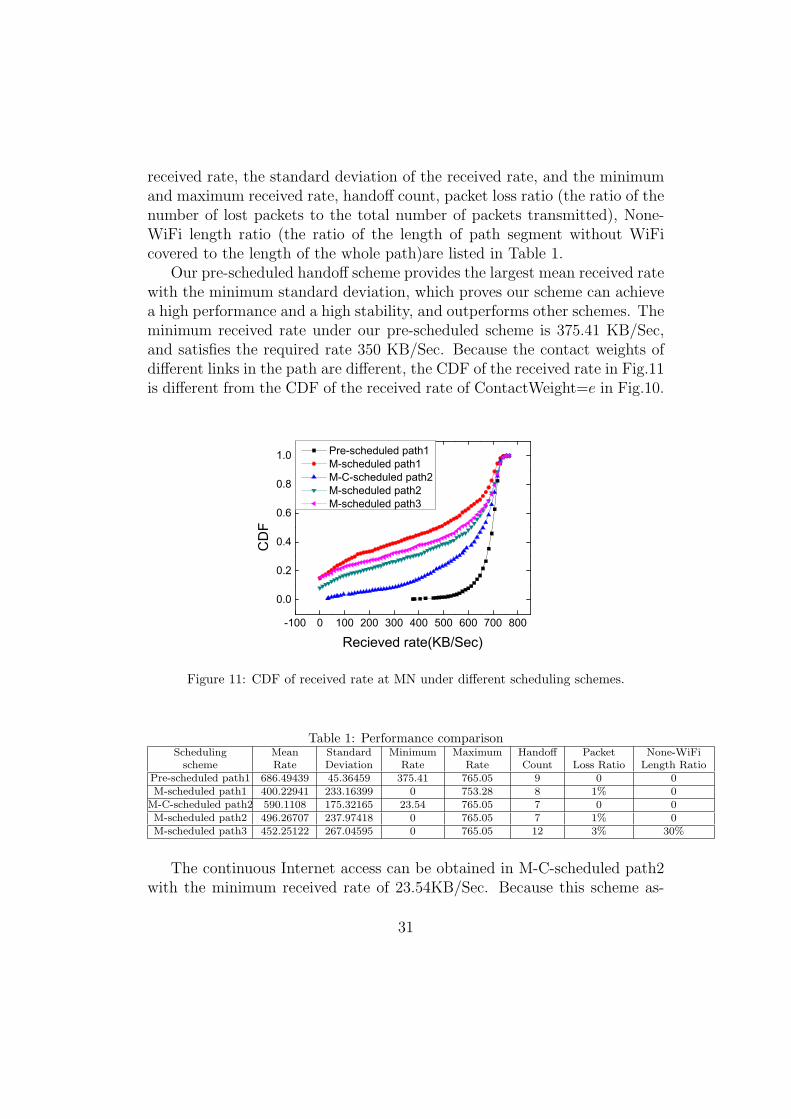
received rate, the standard deviation of the received rate, and the minimumand maximum received rate, handoff count, packet loss ratio (the ratio of thenumber of lost packets to the total number of packets transmitted), None-WiFi length ratio (the ratio of the length of path segment without WiFicovered to the length of the whole path)are listed in Table 1.
Our pre-scheduled handoff scheme provides the largest mean received ratewith the minimum standard deviation, which proves our scheme can achievea high performance and a high stability, and outperforms other schemes. Theminimum received rate under our pre-scheduled scheme is 375.41 KB/Sec,and satisfies the required rate 350 KB/Sec. Because the contact weights ofdifferent links in the path are different, the CDF of the received rate in Fig.11is different from the CDF of the received rate of ContactWeight=e in Fig.10.
-100 0 100 200 300 400 500 600 700 800
0.0
0.2
0.4
0.6
0.8
1.0
CD
F
Recieved rate(KB/Sec)
Pre-scheduled path1 M-scheduled path1 M-C-scheduled path2 M-scheduled path2 M-scheduled path3
Figure 11: CDF of received rate at MN under different scheduling schemes.
Table 1: Performance comparisonSchedulingscheme
MeanRate
StandardDeviation
MinimumRate
MaximumRate
HandoffCount
PacketLoss Ratio
None-WiFiLength Ratio
Pre-scheduled path1 686.49439 45.36459 375.41 765.05 9 0 0M-scheduled path1 400.22941 233.16399 0 753.28 8 1% 0
M-C-scheduled path2 590.1108 175.32165 23.54 765.05 7 0 0M-scheduled path2 496.26707 237.97418 0 765.05 7 1% 0M-scheduled path3 452.25122 267.04595 0 765.05 12 3% 30%
The continuous Internet access can be obtained in M-C-scheduled path2with the minimum received rate of 23.54KB/Sec. Because this scheme as-
31

sumes the optimal scheduling strategies for mobility and connection andselects the path 2 based on the coverage connection considered in this paper,the intermittent Wi-Fi coverage is avoided. However, there is no minimumrate guarantee. The minimum received rate in M-C-scheduled path 2 is onlyabout 6 percent of the minimum received rate in Pre-scheduled path 1.
Although a mobile user moves on a fully Wi-Fi covered path, the mobileuser cannot obtain the continuous Seamless Internet access in M-scheduledpath1 and M-scheduled path2. Similar to the results of the linear network inFig.9, as the connection procedure is not optimized in these two schemes, alarge handoff delay leads to the outage of transmission and thus the packetloss.
In Pre-scheduled path1 and M-C-scheduled path2, the connection is wellscheduled to significantly reduce the scanning delay, so there is no packetloss in these two schemes. Although M-scheduled path3, M-scheduled path1,and M-scheduled path2 adopt the same connection procedure, the packetloss ratio in M-scheduled path3 is the largest, as it simply takes the shortestpath without any Wi-Fi covered guarantee. When mobile users move to thecoverage boundary of MRs, the weak signal leads to higher communicationoutage rate and thus large packet loss ratio.
Among all the five schemes, M-C-scheduled path2 and M-scheduled path2have the lowest handoff count as path2 is chosen with the minimum handofffrequency. However, path2 is chosen without considering the QoS require-ment. Although in M-C-scheduled path2 a user moves along the path withthe minimum handoff count, its received rate is much worse than that underPre-scheduled path1.
7.3.2. Performance Comparison With Different STA Distribution
To study the performance of a network with non-uniform STA distribu-tion, Fig.12 shows the performance result under two non-uniform STA dis-tribution scenarios. We observe that, although our proposed contact weightdefinition may either overestimate or underestimate the coverage overlap oftwo neighboring MRs, the minimum received rate achieved under our schemeis still much better than that achieved under M-scheduled path3 in which themobile user moves along the shortest path. These results prove the effective-ness of our scheme in finding a good WiFi covered path.
In summary, all the results show that our pre-scheduled handoff schemecan provide appealing high data rates with the minimum handoff delay formobile users.
32

-100 0 100 200 300 400 500 600 700 800
0.0
0.2
0.4
0.6
0.8
1.0
CD
F
Recieved rate(KB/Sec)
M-scheduled path3(scenario1) Pre-scheduled path1(scenario1) M-scheduled path3(scenario2) Pre-scheduled path1(scenario2)
Figure 12: Performance Comparison With Different STA Distribution.
8. Algorithm Overhead
To enable the proposed routing scheme, it is important to obtain themetric ContactWeight. We analyze the message cost to obtain the necessaryparameters and the cost for calculating the metric.
The Bloom filter vector that represents the STA set covered by MRs needsto be exchanged among MRs. As discussed earlier, one major reason for usto choose the Bloom filter is that it is a succinct data structure and is widelyapplied in the distributed system to enable low-cost message exchanges.
Given SBF1 and SBF2 which represent the two STA sets covered byMR1
and MR2 respectively, to calculate the degree of coverage overlapping of apair of MRs as shown in Eq(2), we first make use of the union property ofBloom filter in Theorem 1 to estimate the cardinality of the set union usingthe Theorem 2. We then find the degree of coverage overlapping based onthe estimated set sizes of S1, S2, S1 ∪ S2, and S1 ∩ S2.
The cost on calculating the degree of coverage overlapping is low. Given aBloom filter, to estimate the size of STA set represented by the Bloom filter,the cost for counting the number of ”1” in a Bloom filter of length m is O(m).Also, our proposed probabilistic estimation is performed based on simplebinary operations of Bloom filter strings, which can be easily implementedon well-designed hardware at the low complexity.
The load of an MR can be estimated based on the total traffic of itsassociated users, which can be easily obtained from the existing 802.11 MR
33

products. After each MR estimates its load information, the information willbe exchanged among its neighboring MRs to facilitate the calculation of theContactWeight of a link. The message exchange cost is low.
For the message cost in path finding procedure, by defining the link cost in(7), the original path finding problem in (6) is transformed into the problemin (8) to look for a path with the minimum accumulated cost of all links.To solve problem, only the information of link cost (defined in (7)) needs tobe exchanged among nodes to calculate the path table. The communicationcost is not high. Moreover, although the handoff count is considered in thepath finding, this can be automatically taken care when minimizing the pathcost (8) without incurring extra cost.
Therefore, our pre-handoff scheme introduces simple calculation to mea-sure the proposed metric. The communciation cost and calculation costintroduced by our pre-handoff scheme is low.
9. CONCLUSION
In this paper, we study a novel service-aware and seamless Internet accessproblem, and propose a fully distributed and pre-scheduled handoff schemeto solve the problem. In our scheme, mobility and connection are well sched-uled for the mobile users to continuously access Internet with his expecteddata rate. Several novel techniques are proposed. First, we propose two nov-el path finding metrics (contact weight and handoff count) which are closelyrelated to the quality of data service that a mobile user might experiencewhen moving through the network. Second, to measure the path metric ina practical mesh network with irregular and dynamic MR coverage, we firstpropose a light-weight polling algorithm which exploits Bloom filter to quick-ly discover the STAs covered in MR, and then further apply the Bloom filterto estimate the degree of coverage overlapping among MRs. Third, based onthe metrics, to flexibly support performance requirements of mobile users,we propose a fully distributed multi-service-class path finding algorithm. Fi-nally, we propose a cross-layer pre-scheduled connection strategy where bothL2 and L3 handoffs are pre-scheduled on the path for the mobile users. Theperformance results demonstrate that our pre-scheduled handoff scheme caneffectively support network connectivity and with a much higher data rate,as compared with the reference schemes.
Instead of relying on the current opportunistic handoff schemes, provid-ing a better-covered path may allow the support of some advanced wireless
34

applications which have higher requirements on network connectivity andtransmission quality. For example, a user may hold a wireless terminal tomonitor a remote site. With the support of the pre-scheduled handoff, theuser can obtain a seamless network access and high quality surveillance video.This application can be used by policeman on the move to better monitor apublic space for security.
In this paper, we focus on finding a Wi-Fi covered path to provide themobile user seamless and high received date rate. To provide the mobileusers with flexible QoS support, in our future work, we will take account thedelay and jitter into path finding procedure.
Acknowledgment
The work is supported by the National Natural Science Foundation ofChina under Grant No. 61572184, U.S. National Science Foundation underGrant Nos. ECCS-1231800 and CNS 1247924.
[1] S. Vural, D. Wei, K. Moessner, Survey of experimental evaluation studiesfor wireless mesh network deployments in urban areas towards ubiqui-tous internet, IEEE Communications Surveys Tutorials 15 (1) (2013)223–239. doi:10.1109/SURV.2012.021312.00018.
[2] P. Guo, J. Wang, X. H. Geng, C. S. Kim, J.-U. Kim, A variablethreshold-value authentication architecture for wireless mesh networks,Journal of Internet Technology 15 (6) (2014) 929–935.
[3] J. Cao, K. Xie, W. Wu, C. Liu, G. Yao, W. Feng, Y. Zou, J. Wen,C. Zhang, X. Xiao, et al., Hawk: Real-world implementation of high-performance heterogeneous wireless network for internet access, in: ICD-CS Workshop on Distributed Computing Systems, IEEE, 2009.
[4] A. Mishra, M. Shin, W. A. Arbaush, Context caching using neighborgraphs for fast handoffs in a wireless network, in: INFOCOM 2004.
[5] S. Pack, H. Jung, T. Kwon, Y. Choi, SNC: a selective neighbor cachingscheme for fast handoff in IEEE 802.11 wireless networks, ACM SIG-MOBILE Mobile Computing and Communications Review 9 (4) (2005)39–49.
35

[6] S. Pack, J. Choi, T. Kwon, Y. Choi, Fast-handoff support in IEEE802.11 wireless networks, IEEE Communications Surveys & Tutorials9 (1) (2007) 2–12.
[7] H. Soliman, L. Bellier, K. E. Malki, Hierarchical mobile IPv6 mobilitymanagement (HMIPv6).
[8] R. Koodli, Fast handovers for mobile IPv6, IETF RFC 4068.
[9] B. Rong, Y. Qian, K. Lu, R. Hu, M. Kadoch, Mobile-agent-based hand-off in wireless mesh networks: Architecture and call admission control,IEEE Transactions on Vehicular Technology 58 (8) (2009) 4565–4575.doi:10.1109/TVT.2009.2021062.
[10] M. Buddhikot, A. Hari, K. Singh, S. Miller, Mobilenat: A new techniquefor mobility across heterogeneous address spaces, Mobile Networks andApplications 10 (3) (2005) 289–302.
[11] K. Ramachandran, M. Buddhikot, G. Chandranmenon, S. Miller,E. Belding-Royer, K. Almeroth, On the design and implementation ofinfrastructure mesh networks, in: WiMesh 2005.
[12] S. Speicher, C. H. Cap, Fast layer 3 handoffs in AODV-based IEEE802.11 wireless mesh networks, in: ISWCS 2006.
[13] S. Speicher, OLSR-FastSync: fast post-handoff route discovery in wire-less mesh networks, in: VTC 2006.
[14] R. Huang, C. Zhang, Y. Fang, A mobility management scheme for wire-less mesh networks, in: GLOBECOM 2007.
[15] V. Navda, A. Kashyap, S. R. Das, Design and evaluation of imesh: aninfrastructure-mode wireless mesh network, in: WoWMoM 2005.
[16] Y. Amir, C. Danilov, M. Hilsdale, R. Musloiu-Elefteri, N. Rivera, Fasthandoff for seamless wireless mesh networks, in: Proceedings of the 4thinternational conference on Mobile systems, applications and services,ACM, 2006.
[17] Y. Zhang, Handoff performance in wireless mobile networks with unre-liable fading channel, IEEE Transactions on Mobile Computing 9 (2)(2010) 188–200.
36

[18] R. Wishart, M. Portmann, J. Indulska, Evaluation of wireless mesh net-work handoff approaches for public safety and disaster recovery network-s, in: ATNAC 2008.
[19] Y. Yang, D. Zhao, Joint handoff and energy management for a wirelessmesh network, in: ICC 2011.
[20] H. Li, J. Xie, An adaptive channel scheduling design for multi-hophandoff delay reduction in internet-based wireless mesh networks, IEEETransactions on Wireless Communications 12 (10) (2013) 5258–5270.
[21] H. Li, J. Xie, X. Wang, A channel splitting strategy for reduc-ing handoff delay in internet-based wireless mesh networks, IEEETransactions on Vehicular Technology 61 (6) (2012) 2740–2752.doi:10.1109/TVT.2012.2195512.
[22] W. Zhao, J. Xie, IMeX: Intergateway cross-layer handoffs in internet-based infrastructure wireless mesh networks, IEEE Transactions on Mo-bile Computing 11 (10) (2012) 1585–1600. doi:10.1109/TMC.2011.192.
[23] P. Deshpande, A. Kashyap, C. Sung, S. R. Das, Predictive methods forimproved vehicular WiFi access, in: MobiSys 2009.
[24] Y. Chon, H. Shin, E. Talipov, H. Cha, Evaluating mobility models fortemporal prediction with high-granularity mobility data, in: PerCom2012.
[25] N. Vishnu, S. Anand Prabhu, D. Kannan, T.-G. Andreas, D. Samir, Mo-biSteer: using steerable beam directional antenna for vehicular networkaccess, in: MobiSys 2007.
[26] A. P. Subramanian, P. Deshpande, G. Jie, S. R. Das, Drive-by localiza-tion of roadside WiFi networks, in: INFOCOM 2008.
[27] V. Bychkovsky, B. Hull, A. Miu, H. Balakrishnan, S. Madden, A mea-surement study of vehicular internet access using in situ wi-fi networks,in: MobiCom 2006.
[28] J. Ott, D. Kutscher, A disconnection-tolerant transport for drive-thruinternet environments, in: INFOCOM 2005.
37

[29] J. Ott, D. Kutscher, Drive-thru internet: Ieee 802.11 b for” automobile”users, in: INFOCOM 2004.
[30] V. Navda, A. P. Subramanian, K. Dhanasekaran, A. Timm-Giel, S. Das,Mobisteer: using steerable beam directional antenna for vehicular net-work access, in: Proceedings of the 5th international conference on Mo-bile systems, applications and services, ACM, 2007, pp. 192–205.
[31] A. Mishra, M. Shin, W. Arbaugh, An empirical analysis of the IEEE802.11 MAC layer handoff process, ACM SIGCOMM Computer Com-munication Review 33 (2) (2003) 93–102.
[32] H. Li, J. Xie, GaS: A gateway scheduling-based handoff scheme in single-radio infrastructure wireless mesh networks, in: INFOCOM, 2013.
[33] W. Zhao, J. Xie, A novel xcast-based caching architecture for inter-gateway handoffs in infrastructure wireless mesh networks, in: INFO-COM, 2010.
[34] V. Navda, S. R. Das, Design and evaluation of iMesh: An infrastructure-mode wireless mesh network, in: WoWMoM 2005.
[35] R. K. Sheshadri, D. Koutsonikolas, An experimental study of routingmetrics in 802.11 n wireless mesh networks, IEEE Transactions on Mo-bile Computing 13 (12) (2014) 2719–2733.
[36] D. Couto, D. Aguayo, J. Bicket, R. Morris, a high-throughput pathmetric for multi-hop wireless routing, Wireless Networks 11 (2005) 419–434. doi:10.1007/s11276-005-1766-z.URL http://dx.doi.org/10.1007/s11276-005-1766-z
[37] R. Draves, J. Padhye, B. Zill, Routing in multi-radio, multi-hop wirelessmesh networks, in: MobiCom, 2004.
[38] Y. Yang, J. Wang, R. Kravets, Load-balanced routing for mesh network-s, ACM SIGMOBILE Mobile Computing and Communications Review10 (4) (2006) 3–5.
[39] H. Wu, F. Yang, K. Tan, J. Chen, Q. Zhang, Z. Zhang, Distributedchannel assignment and routing in multiradio multichannel multihopwireless networks, IEEE Journal on Selected Areas in Communications24 (11) (2006) 1972 –1983. doi:10.1109/JSAC.2006.881638.
38

[40] K. Xie, X. Wang, X. Liu, J. Wen, J. Cao, Interference-aware cooperativecommunication in multi-radio multi-channel wireless networks, IEEETransactions on Computers 65 (5) (2016) 1528–1542.
[41] K. Xie, X. Wang, J. Wen, J. Cao, Cooperative routing with relay as-signment in multiradio multihop wireless networks, IEEE/ACM Trans-actions on Networking 24 (2) (2016) 859–872.
[42] A. Broder, M. Mitzenmacher, Network applications of bloom filters: Asurvey, Internet Mathematics (2002) 636–646.
[43] T. Hagerup, C. Rub, A guided tour of chernoff bounds, Informationprocessing letters 33 (6) (1990) 305–308.
[44] D. Bertsekas, R. Gallager, Data networks. 2nd ed., in: Prentice Hall1991.
[45] S.-Y. Wang, C.-C. Lin, NCTUns 6.0: A simulator for advanced wirelessvehicular network research, in: VTC 2010, 2010.
[46] G. Tan, J. Guttag, Time-based fairness improves performance in multi-rate Wlans, in: USENIX Annual Technical Conference, 2004.
39