Embed Size (px)
Citation preview

An Information Report of the Joint Committee on the NTCIP
Pre-Publication DRAFT by AASHTO, ITE, and NEMA
NTCIP 9001 v02.05 (Draft)
The NTCIP GuideNational Transportation Communications for ITS Protocol
September 1999
This is a draft document, which is distributed for review and comment purposes only. You may reproduce and distribute thisdocument to facilitate review and comment to the NTCIP Guide Project Manager through the NTCIP Coordinator. Please ensurethat all copies reproduced or distributed bear this legend. This document contains information that is subject to change.
Published by
American Association of State Highway and Transportation Officials (AASHTO)444 North Capitol St., N.W., Suite 249Washington, D.C. 20001
Institute of Transportation Engineers (ITE)525 School St., S.W., Suite 410Washington, D.C. 20024-2797
National Electrical Manufacturers Association (NEMA)1300 N. 17th Street, Suite 1847Rosslyn, Virginia 22209-3801
Copyright 1999 by the American Association of State Highway and Transportation Officials (AASHTO), the Institute ofTransportation Engineers (ITE), and the National Electrical Manufacturers Association (NEMA). All intellectual property rights arereserved, except as described as follows, by the copyright owners under the laws of the United States of America, the UniversalCopyright Convention, the Berne Convention, and the International and Pan American Copyright Conventions. Permission to freelyreproduce, distribute, and/or translate into other languages is granted provided that (1) this copyright notice appears on the front ofthe document, (2) “© 1999 AASHTO, ITE, NEMA” appears on every page of the text, and (3) the text is not edited or used out ofcontext.
NTCIP is a trademark of AASHTO/ITE/NEMA.

NTCIP 9001 v02.05Page ii
© 1999 AASHTO, ITE, NEMA
Acknowledgements
The NTCIP development effort is guided by the NTCIP Joint Committee, which consists of sixrepresentatives each from the American Association of State Highway and TransportationOfficials (AASHTO), the Institute of Transportation Engineers (ITE), and the National ElectricalManufacturers Association (NEMA). This NTCIP Guide is one of the many NTCIP documentsdeveloped under a cooperative agreement among these organizations.
Members of the NTCIP Joint Committee include:• Craig Anderson• Paul Bell• Jack Bailey• Jack Brown• David Cordone• Gary Duncan• Curt Gobeli• Michael Forbis• Alex Lopez
• Phil Nicholes• Raman Patel• Colin Rayman• Dave Russo• Ed Seymour• Issac Takyi• Warren Tighe• Ken Vaughn
The previous edition of the NTCIP Guide was prepared in February 1997. Realizing that it hadbecome outdated, the NTCIP Joint Committee initiated a project to develop an updated guidedocument. The NTCIP Guide Update Team has prepared this document as part of that project,with direction from the NTCIP Joint Committee and input from a peer review team selected forthis effort.
At the time that this document was prepared, the following individuals were members of theNTCIP Guide Update Team:
• G. Curtis Herrick, Project Manager and Principal Author• Gary Duncan, Principal Author• Craig C. Gardner, Principal Author• Robert de Roche, Principal Author• Kenneth L. Vaughn, Principal Author• Paul Bell, Principal Author• Warren A. Tighe, Principal Author• Joe Stapleton, Peer Review Team Leader
NTCIP 9001 v02.05Page iii
© 1999 AASHTO, ITE, NEMA
Other individuals providing Peer Review and input to the document, include:• Jack Brown• Randy Bundy• Joseph Crabtree• Mike Crow• Steve Dellenback• Wayne Henley• Les Jacobson• Al Kosik• James Mona
• Paul Olson• Raman Patel• Jim Pursell• Colin Rayman• J. R. Robinson• Mike Robinson• Ed Seymour• David Spinney• James Wright
In addition to the many volunteer efforts, recognition is also given to those organizations whosupported the efforts of the NTCIP Guide Update by providing guidance, comments and fundingfor the effort:
• ARINC, Inc.• California Department of Transportation• City of Atlanta• Connecticut Department of Transportation• Eagle Traffic Control Systems, Inc.• Econolite Control Products, Inc.• Florida Department of Transportation• Federal Highway Administration• Gardner Transportation Systems, Inc.• Georgia Department of Transportation• Houston Metropolitan Transit Authority• Image Sensing Systems, Inc.• Kansas Department of Transportation• Kentucky Transportation Center• Minnesota Department of Transportation• New York City Transit Authority• New York Department of Transportation• Odetics ITS, Inc.• Ontario Ministry of Transportation• P. B. Farradyne, Inc.• PEEK Traffic Systems, Inc.• Southwest Research Institute• Texas Department of Transportation• Texas Transportation Institute• Virginia Department of Transportation• Washington State Department of Transportation

NTCIP 9001 v02.05Page iv
© 1999 AASHTO, ITE, NEMA
CONTENTS
1 Foreword 11.1 Disclaimer ...................................................................................................................................11.2 Purpose of the NTCIP Guide .......................................................................................................11.3 Organization of the NTCIP Guide ................................................................................................21.4 Additional Information..................................................................................................................3
2 Executive Summary 42.1 Introduction .................................................................................................................................42.2 Overview of NTCIP......................................................................................................................42.3 What is NTCIP? ..........................................................................................................................62.4 Why Do We Need NTCIP? ..........................................................................................................62.5 Lessons Learned.........................................................................................................................72.6 Resources...................................................................................................................................8
2.6.1 Training ...............................................................................................................................82.6.2 Technical Abilities ................................................................................................................92.6.3 Projects ...............................................................................................................................92.6.4 Compliance Testing .............................................................................................................9
3 Understanding NTCIP 103.1 Introduction ............................................................................................................................... 103.2 Benefits of NTCIP ..................................................................................................................... 10
3.2.1 Avoid Early Obsolescence ................................................................................................. 113.2.2 Provide Choice of Vendor .................................................................................................. 113.2.3 Enable Interagency Coordination ....................................................................................... 113.2.4 Use One Communications Network for All Purposes .......................................................... 12
3.3 Types of Systems and Devices Supported by NTCIP................................................................. 123.4 Applications Not Addressed by NTCIP....................................................................................... 143.5 The Levels or Modules Involved in NTCIP Communications ...................................................... 153.6 The NTCIP Framework.............................................................................................................. 163.7 NTCIP Standards and Protocol Stacks ...................................................................................... 193.8 Options and Conformance Levels.............................................................................................. 203.9 Center-to-Center Protocols........................................................................................................ 203.10 Center-to-Field Protocols ........................................................................................................ 223.11 Communications Infrastructure for Center-to-Field .................................................................. 233.12 Retrofitting Existing Center-to-Field Systems with NTCIP........................................................ 24
4 Procuring NTCIP 264.1 Introduction ............................................................................................................................... 264.2 Procurement Roadmap ............................................................................................................. 27
4.2.1 Procurement Request ........................................................................................................ 284.2.2 Proposal Initiation .............................................................................................................. 284.2.3 Investigate Issues .............................................................................................................. 29
4.2.3.1 Requirements ............................................................................................................... 294.2.3.1.1 How NTCIP Standards Fit Together ......................................................................... 304.2.3.1.2 Selecting Standards and Conformance Statements.................................................. 324.2.3.1.3 Manufacturer Extensions.......................................................................................... 32
4.2.3.2 Implementation Alternatives .......................................................................................... 324.2.3.3 Other Factors................................................................................................................ 33
4.2.3.3.1 Stability of the Standard ........................................................................................... 344.2.3.3.2 Support of Amendments........................................................................................... 344.2.3.3.3 Agency / Developer Understanding .......................................................................... 344.2.3.3.4 Certification Process ................................................................................................ 344.2.3.3.5 Performance Issues ................................................................................................. 34
4.2.4 Proposal Submission ......................................................................................................... 354.2.5 Delivery / Acceptance Testing............................................................................................ 35
4.2.5.1 Unit Testing .................................................................................................................. 35
NTCIP 9001 v02.05Page v
© 1999 AASHTO, ITE, NEMA
4.2.5.2 Integration Testing ........................................................................................................ 364.2.5.3 System Testing............................................................................................................. 36
4.2.6 Maintenance...................................................................................................................... 364.2.7 Design Requirements ........................................................................................................ 374.2.8 Testing Requirements........................................................................................................ 38
4.3 Center-to-Field .......................................................................................................................... 384.3.1 NTCIP Stack Options......................................................................................................... 404.3.2 Available Resources for Additional Information................................................................... 43
4.3.2.1 NTCIP Specification Development Examples ................................................................ 444.3.2.1.1 NTCIP Stack for Center-to-Field Traffic Signal Controller ......................................... 444.3.2.1.2 Conformance Group and Data Object Selection for Traffic Signal Controllers ........... 464.3.2.1.3 Object Range Values for an Actuated Traffic Signal Controller ................................. 53
4.4 Center-to-Center ....................................................................................................................... 555 Designing NTCIP 59
5.1 Introduction ............................................................................................................................... 595.2 Calculate Bandwidth Requirements ........................................................................................... 59
5.2.1 Center-to-Center Bandwidth Requirements ........................................................................ 605.2.2 Center-to-Field Bandwidth Requirements........................................................................... 615.2.3 Center-to-Field Bandwidth Analysis.................................................................................... 62
5.2.3.1 Estimate Message Exchanges and Frequency .............................................................. 635.2.3.2 Estimate Application Message Size............................................................................... 66
5.2.3.2.1 SNMP Application Message Bits and Bytes.............................................................. 665.2.3.2.2 STMP Application Message Bits and Bytes .............................................................. 68
5.2.3.3 Estimate Application Message Exchanges .................................................................... 695.2.3.3.1 SNMP Application Message Exchange Sizes ........................................................... 705.2.3.3.2 STMP Application Message Exchange Sizes ........................................................... 70
5.2.3.4 Estimate Transport and Subnetwork Protocol Size ........................................................ 715.2.3.5 Estimate Timing Factors ............................................................................................... 745.2.3.6 Modems ....................................................................................................................... 77
5.2.3.6.1 Electrical Limitations ................................................................................................ 775.2.3.6.2 Communications Limitations..................................................................................... 79
5.2.3.7 SNMP Timing ............................................................................................................... 805.2.3.8 STMP Timing................................................................................................................ 82
5.2.4 Center-to-Field Bandwidth Alternate Analysis..................................................................... 845.2.4.1 Estimate Message Exchanges and Frequency .............................................................. 84
5.2.4.1.1 SNMP Application Message Exchange Sizes ........................................................... 855.2.4.1.2 STMP Application Message Exchange Sizes ........................................................... 85
5.2.4.2 Other Estimates............................................................................................................ 865.2.4.3 Number and Size of Slots per Channel ......................................................................... 865.2.4.4 Communications Drops (Drops per Channel) ................................................................ 875.2.4.5 SNMP Timing ............................................................................................................... 885.2.4.6 STMP Timing................................................................................................................ 91
6 Implementing NTCIP 946.1 Introduction ............................................................................................................................... 946.2 Implementation Roadmap ......................................................................................................... 95
6.2.1 Initial Request.................................................................................................................... 966.2.2 Investigate Issues .............................................................................................................. 96
6.2.2.1 Device and/or System Requirements ............................................................................ 976.2.2.1.1 How NTCIP Standards Fit Together ......................................................................... 976.2.2.1.2 Selecting Standards for an Implementation .............................................................. 996.2.2.1.3 Selecting Manufacturer Extensions ........................................................................ 100
6.2.2.2 Implementation Alternatives ........................................................................................ 1006.2.2.3 Other Factors.............................................................................................................. 101
6.2.2.3.1 Stability of the Standard ......................................................................................... 1016.2.2.3.2 Support of Amendments......................................................................................... 1016.2.2.3.3 Interpretation Resolution ........................................................................................ 101

NTCIP 9001 v02.05Page vi
© 1999 AASHTO, ITE, NEMA
6.2.2.3.4 Client/Developer Understanding............................................................................. 1026.2.2.3.5 Certification Process .............................................................................................. 1026.2.2.3.6 Integration with other components.......................................................................... 1026.2.2.3.7 Performance Issues ............................................................................................... 1026.2.2.3.8 Maintenance / Future Upgrades ............................................................................. 103
6.2.3 Development ................................................................................................................... 1036.2.4 Delivery / Acceptance Testing.......................................................................................... 103
6.2.4.1 Unit Testing ................................................................................................................ 1036.2.4.2 Integration Testing ...................................................................................................... 1036.2.4.3 System Testing........................................................................................................... 104
6.2.5 Maintenance.................................................................................................................... 1046.3 Example Implementation Process............................................................................................ 104
6.3.1 The Request .................................................................................................................... 1046.3.2 The Investigation ............................................................................................................. 106
6.3.2.1 Requirements ............................................................................................................. 1066.3.2.1.1 Interpretation ......................................................................................................... 1066.3.2.1.2 Questions Arising from Requirements Review ........................................................ 108
6.3.2.2 Implementation Alternatives ........................................................................................ 1096.3.2.3 Other Factors.............................................................................................................. 109
6.3.2.3.1 Stability of the Standard ......................................................................................... 1096.3.2.3.2 Support of Amendments......................................................................................... 1106.3.2.3.3 Interpretation Resolution ........................................................................................ 1106.3.2.3.4 Client / Developer Understanding........................................................................... 1106.3.2.3.5 Certification Process .............................................................................................. 1116.3.2.3.6 Integration with Other Components ........................................................................ 1116.3.2.3.7 Performance Issues ............................................................................................... 1116.3.2.3.8 Maintenance / Upgrades ........................................................................................ 111
6.3.3 Proposal .......................................................................................................................... 1116.4 Example Byte Streams ............................................................................................................ 115
6.4.1 The NTCIP Database....................................................................................................... 1156.4.2 Encoding the NTCIP Database for Transmission.............................................................. 120
6.4.2.1 Encoding an Object with Its Value............................................................................... 1206.4.2.2 Encoding the SNMP Data Packet................................................................................ 1226.4.2.3 The Transport Profile .................................................................................................. 1246.4.2.4 The Subnetwork Profile............................................................................................... 125
6.5 Defining New Objects.............................................................................................................. 1256.6 Examples of Implementation Problems.................................................................................... 125
6.6.1 Protocol-Related Issues ................................................................................................... 1256.6.1.1 Bit and Byte Order ...................................................................................................... 1266.6.1.2 Extended Addresses................................................................................................... 1266.6.1.3 Maximum Duration Between Successive Bytes ........................................................... 1266.6.1.4 Response Time .......................................................................................................... 1266.6.1.5 Control Byte................................................................................................................ 1276.6.1.6 Frame Handling .......................................................................................................... 1276.6.1.7 CRC Algorithm............................................................................................................ 1286.6.1.8 Invalid Frame.............................................................................................................. 1286.6.1.9 STMP Message Type Byte ......................................................................................... 1286.6.1.10 Length Values for Variable Message Fields.............................................................. 129
6.6.2 Systems Integration Issues .............................................................................................. 1296.6.2.1 Carriers ...................................................................................................................... 1296.6.2.2 Number of Devices on a Channel................................................................................ 1296.6.2.3 MIB Issues.................................................................................................................. 129
6.7 Development Resources ......................................................................................................... 1306.7.1 Web Sites ........................................................................................................................ 1306.7.2 Sources of Public Domain Software ................................................................................. 131
6.7.2.1 NTCIP Exerciser ......................................................................................................... 131

NTCIP 9001 v02.05Page vii
© 1999 AASHTO, ITE, NEMA
6.7.2.2 Field Device Simulator ................................................................................................ 1316.7.3 Books .............................................................................................................................. 1316.7.4 Other Resources.............................................................................................................. 132
6.8 Summary ................................................................................................................................ 1327 Glossary 133
7.1 Acronyms................................................................................................................................ 1337.2 Definitions ............................................................................................................................... 135
8 Bibliography 1398.1 Selected Reading List ............................................................................................................. 139
9 Example NTICP Implementations 1409.1 Center-to-Field ........................................................................................................................ 140
9.1.1 Example Center-to-Field Implementation Without Routing................................................ 1409.1.2 Example Center-to-Field Implementation With Routing..................................................... 141
9.2 Center-to-Center ..................................................................................................................... 1439.2.1 Example Center-to-Center Implementation using DATEX................................................. 1439.2.2 Example Center-to-Center Implementation using CORBA................................................ 144
10 NTICP Documents 14610.1 Listing of NTCIP Documents ................................................................................................. 146

NTCIP 9001 v02.05Page viii
© 1999 AASHTO, ITE, NEMA
This Page Left Intentionally Blank

NTCIP 9001 v02.05Page 1
© 1999 AASHTO, ITE, NEMA
NTCIP Guide
1 FOREWORD
The National Transportation Communications for ITS Protocol (NTCIP) is receivingconsiderable attention these days. The transportation community has long needed a mechanismwhereby interchangeability and interoperability amongst the various components oftransportation systems could be achieved. It is for this reason that NTCIP is being widelyembraced and is being specified in many new system deployments.
Interchangeability is defined as the capability to exchange devices of the same type (e.g., a signalcontroller from different vendors) without changing the software. Interoperability is defined asthe capability to operate devices from different manufacturers, or different device types (e.g.,signal controllers and dynamic message signs) on the same communications channel.
1.1 Disclaimer
It is well understood that, because of the need for technical precision, accuracy, andcompleteness in standards documents, these documents are often very difficult to read. Thus thisNTCIP Guide is an educational tool that has been created to assist decision makers, planners,specification writers, and implementers understand the various NTCIP standards documents andhow to use them, as well as the overall motivations behind the use of NTCIP. This document isan NTCIP standards document, but it is not an NTCIP standard and must therefore not beconsidered a binding specification. The NTCIP suite of standards documents is comprised ofnumerous stand alone documents, some of which have been fully approved, some of which are inthe approval process, and some of which are still being drafted. Further, as the NTCIP conceptcontinues to grow in transportation community acceptance, the need will no doubt arise foradditional NTCIP standards documents, the subject of which has not yet been established. As aresult, there is a strong likelihood that at any given point in time this document may be out ofsync in some respects with the actual standards documents. While every reasonable effort willbe made to keep this document current, the reader should understand that, in writingspecifications or implementing systems, only the actual NTCIP standards documents govern, notthis NTCIP Guide.
1.2 Purpose of the NTCIP Guide
The subject of communications protocols and standards is a challenging one, even for engineersexperienced in these issues. In the case of NTCIP, the level of difficulty is heightened by thefact that NTCIP is a whole suite of documents and protocols aimed at meeting thecommunications needs of the various fixed-point communications components of the NationalITS Architecture, not just a single one. This NTCIP Guide is an educational tool that has beencreated to assist decision makers, planners, specification writers, and implementers understand

NTCIP 9001 v02.05Page 2
© 1999 AASHTO, ITE, NEMA
the various NTCIP standards documents and how to use them, as well as the overall motivationsbehind the use of NTCIP.
1.3 Organization of the NTCIP Guide
The Executive Summary of this NTCIP Guide is intended principally for decision makers. Thissection provides a brief overview of the NTCIP as well as a discussion of the motivations behindthe use of these approaches, cast largely in the context of the National ITS Architecture. It alsodiscusses the issues associated with NTCIP use, as well as required resources, testing, andconfiguration management issues.
The Understanding NTCIP section of this guide is intended principally for systems planners,though it is also intended to be a general purpose technical overview of the issues associated withthe use of NTCIP, and is a good starting point for anyone wishing to become better informed onthe various technical aspects of the approach.
The Procuring NTCIP section is intended principally for specification writers. As the NTCIPstandards suite consists of many documents, and many have numerous optional requirements, itis very important that specification writers have a good grasp of the decision process by whichthese various options will be deemed necessary or unnecessary for any given planneddeployment. Satisfying the user agency in an NTCIP deployment requires a careful analysis ofthe agency’s requirements up front, then a careful mapping of the various NTCIP options tothose requirements by way of a well written procurement specification. Further, this sectiondescribes the need for and a means by which the technical requirements of the communicationsinfrastructure can be determined.
The Designing NTCIP section is intended principally for those faced with the task of designingthe communications element of transportation systems that utilize NTCIP protocols. Thissection includes a detailed discussion on bandwidth analysis and system timing.
The Implementing NTCIP section is intended principally for the various systems implementers,i.e., field equipment software and hardware developers, traffic management center software andhardware developers, and systems integrators. Inasmuch as the principal authors of this NTCIPGuide document consisted of field equipment and central traffic management center softwareand hardware developers and integrators involved in actual NTCIP deployments, it is hoped thatthis section will provide the necessary “read between the lines” type of insight often required toachieve successful deployments. In particular, some of the lessons learned and common pitfallsencountered during actual deployments will be discussed, with suggested solutions given.
The remaining sections provide a listing of terms, abbreviations, acronyms, and definitions. Adocument listing of NTCIP standards and the status each document is also provided. Lastly,example NTCIP stack selections are shown for center-to-field communications using routing andnon-routing protocols.

NTCIP 9001 v02.05Page 3
© 1999 AASHTO, ITE, NEMA
1.4 Additional Information
For more information about NTCIP standards, visit the NTCIP Web Site at http://www.ntcip.org.For a hardcopy summary of NTCIP information, contact the NTCIP Coordinator at the followingaddress.
NTCIP CoordinatorNational Electrical Manufacturers Association1300 N.17th Street, Suite 1847Rosslyn, Virginia 22209-3801fax: (703) 841-3331e-mail: [email protected]
In preparation of this NTCIP document, input of users and other interested parties was soughtand evaluated. Written inquires, comments, and proposed or recommended revisions should besubmitted to the NTCIP Coordinator, at the above address, in the following form:
Document Name:Version Number:Section Number:Paragraph:Comment:
Please include your name, address, and organization in your correspondence.

NTCIP 9001 v02.05Page 4
© 1999 AASHTO, ITE, NEMA
2 EXECUTIVE SUMMARY
2.1 Introduction
A communications protocol is a set of rules for how messages are coded and transmitted betweenelectronic devices. The equipment at each end of a data transmission must use the same protocolto successfully communicate. It is a bit like human languages that have an alphabet, vocabulary,and grammar rules used by everyone speaking that language.
Historically, each vendor of microcomputer control devices and software used in managementsystems adopted a different, proprietary protocol for data communications. This requiredextensive integration projects to mix equipment and software from different vendors in the samesystem and to communicate between systems operated by adjacent agencies. The NationalTransportation Communications for ITS Protocol (NTCIP) provides common protocol standardsthat can be used by all vendors and system developers to help overcome these differences.
NTCIP is a family of communications standards for transmitting primarily data and messagesbetween microcomputer control devices used in Intelligent Transportation Systems (ITS). Anexample of such a system is a computer at city hall monitoring and controlling the operation ofmicroprocessor-based roadside controllers at traffic signals within a city. The computer maysend instructions to the traffic signal controllers to change signal timings as traffic conditionschange and the controllers send status and traffic flow information to the computer.
In another example, two transit management systems (computers) may need to exchange real-time information about the location of transit vehicles bound for a shared timed-transfer center.This allows each system to know instantly when one vehicle is running significantly behindschedule and is unable to make the scheduled transfer time. Passengers can be notifiedautomatically, and the local traffic management center can be automatically requested to providepriority at traffic signals for the delayed transit vehicle.
NTCIP is intended for use in all types of management systems dealing with the transportationenvironment, including those for freeways, traffic signals, transit, emergency management,traveler information, and data archiving. NTCIP is intended for use between computers indifferent systems or different management centers, and between a computer and devices at theroadside. The current NTCIP standards are not intended for use in devices owned by individualtravelers; other standards either currently exist or are in development for that purpose.
2.2 Overview of NTCIP
NTCIP provides communications standards for two fundamentally different types of ITScommunications. The first type is between a management system or center and multiple controlor monitoring devices managed by that system or center. Examples of this type ofcommunications include:

NTCIP 9001 v02.05Page 5
© 1999 AASHTO, ITE, NEMA
• A traffic signal management system communicating with traffic signal controllers atintersections.
• A transit management system communicating with monitoring devices and passengerinformation signs on transit vehicles and at transit stations and stops.
• A freeway management system communicating with detectors and ramp meters onfreeways.
• A traffic management system controlling CCTV cameras, dynamic message signs,advisory radio transmitters, environmental sensors, and traffic count stations onroadways.
Since most applications of this type involve a computer at a management center communicatingwith various devices at the roadside or on agency vehicles, this type is referred to as “center-to-field”. The NTCIP protocols intended for this communications application are often used in anenvironment in which a central management station routinely polls each field device, as in themost common case of multiple field devices sharing a communications channel. This is calledan unbalanced, one-to-many network.
The second type of communication involves messages sent between two or more managementsystems. Examples of this type of communication include:
• Two or more traffic signal management systems exchanging information (includingsecond-by-second status changes) to achieve coordinated operation of traffic signalsmanaged by the different systems and to enable personnel at one center to monitor thestatus of signals operated from another center.
• A transit system reporting schedule adherence exceptions to kiosks, to a transit customerinformation system, and to a regional traveler information system, while also asking atraffic signal management system to instruct its signals to give priority to a behind-schedule transit vehicle.
• An emergency management system reporting an incident to a freeway managementsystem, to a traffic signal management system, to two transit management systems, and toa traveler information system.
• A freeway management system informing an emergency management system of awarning message just posted on a dynamic message sign on the freeway in response to itsnotification of an incident.
This type of communication is referred to as “center-to-center”. It involves peer-to-peercommunications between any number of systems (computers) in what is called a balanced,many-to-many network. This type of communication is similar to the Internet, in that any centercan request information from, or provide information to, any number of other centers. It is

NTCIP 9001 v02.05Page 6
© 1999 AASHTO, ITE, NEMA
possible, though not yet common, to use such protocols for communication to and between fielddevices as well as between computers.
Although both center-to-field and center-to-center communications can involve a humanoperator making requests or issuing instructions, one of the features of the NTCIP protocols istheir support for continuous, automated data transmissions with no human in the loop.
2.3 What is NTCIP?
NTCIP is a suite of communications protocols and data definitions that have been designed toaccommodate the diverse needs of various subsystems and user services of the National ITSArchitecture. It is intended principally to handle these needs in two areas: communicationsbetween a management center and field devices, and communications between two or moremanagement centers. Examples of the first application include transfer of command andconfiguration data between a transportation management center and field devices such as trafficsignal controllers, dynamic message signs, environmental sensor stations, ramp meters, etc.Examples of the second application include transfer of data between multiple managementcenters within one agency, as well as transfer of data between management centers operated bydifferent agencies.
NTCIP differs from past practice in defining communications protocols for management systemsin that it is not a single communications protocol designed for one purpose. Rather it consists ofa whole suite of protocols covering the spectrum from simple point-to-point command/responseprotocols to quite sophisticated object oriented techniques. This is because of the diversity of theapplications into which NTCIP will be deployed, and the resulting diversity of applicationspecific characteristics such as type and quantity of data to be transferred, criticality of datatransfer times, acceptable cost of communications infrastructure, criticality of data security andintegrity issues, to name a few. Insofar as data definitions are concerned, NTCIP does notcompletely define the functionality of the central or field devices to which it applies. It onlyspecifies the data objects to be transferred and limited functionality directly related to theseobjects. For example, NTCIP does not define the details of how a traffic controller operates,e.g., it does not define that a green must be terminated by a yellow and that a red must bedisplayed after a yellow. However, it precisely defines the data that may be communicatedbetween traffic controllers and traffic management centers, and thereby defines the aspects offunctionality (e.g., it requires that the length of the yellow clearance interval must be as indicatedby the phaseYellowChange object).
2.4 Why Do We Need NTCIP?
There have been numerous problems historically associated with the deployments ofmanagement systems. Before describing some of these issues we will first define two terms.The term interchangeability reflects the ability to use multiple brands of a device on the samecommunications channel, along with the ability to swap them out. For example, the ability to putany brand of NTCIP compliant traffic signal controller in the same system at the same time

NTCIP 9001 v02.05Page 7
© 1999 AASHTO, ITE, NEMA
reflects interchangeability. The term interoperability reflects the ability to use many differenttypes of devices on the same communications channel. For example, using the samecommunications channel to interconnect a management system with traffic signal controllers,dynamic message signs, video surveillance controls, and other devices, reflects interoperability.
One common problem historically encountered results from the use of proprietarycommunications protocols in management systems. These protocols are often proprietary to thespecific project, as well as to the specific manufacturers involved in the project. As a result,expansion of the system after initial deployment can generally only be done using equipment ofthe same type and brand as in the initial deployment. There is no opportunity for realisticcompetitive bidding as additional field devices are added to the system (due to the lack ofinterchangeability), nor is there any opportunity to add additional types of field devices to thesystem (due to the lack of interoperability).
The proper use of NTCIP in a management system will allow the future expansion of the systemto benefit from true competitive bidding, as well as allow other types of field devices to beadded.
The Transportation Equity Act for the 21st Century (known as "TEA-21") requires that federallyfunded ITS projects "conform" with the National ITS Architecture. As defined in TEA-21, theterm "intelligent transportation system" means “electronics, communications, or informationprocessing used singly or in combination to improve the efficiency or safety of a surfacetransportation system”. The National ITS Architecture defines both the functions performed inimplementing ITS, and the information flows between transportation subsystems. In its October2, 1998 report entitled “Interim Guidance on Conformity with the National lTS Architecture andStandards”, the US DOT stated “Highway Trust Fund recipients shall take the appropriateactions to ensure that development of the project(s): (a) engages a wide range of stakeholders, (b)enables the appropriate electronic information sharing between shareholders, (c) facilitates futureITS expansion, and (d) considers the use of applicable ITS standards.”
The terms interchangeability and interoperability are used throughout the TEA-21 legislation, butinteroperability is used extensively. While the simple view of NTCIP often focuses oninterchangeability, interoperability is actually far more important, for two reasons. First, sincethe communications infrastructure is usually the most costly element in a new system, using thisinfrastructure for multiple purposes lowers the overall cost of the system. Second, and moreimportant in terms of the TEA-21 legislation, interoperability suggests the sharing of data,thereby enhancing the operators ability to efficiently manage these transportation systems, evento the extent of sharing data across jurisdictional boundaries.
2.5 Lessons Learned
The principal issue associated with the use of NTCIP is that it is an emerging technology intransportation. As is the case with most new or emerging technologies, the early implementerswere on the leading edge of specifying NTCIP. These early implementers often lackedappropriate educational material on the best way to specify, procure, deploy, integrate, and test

NTCIP 9001 v02.05Page 8
© 1999 AASHTO, ITE, NEMA
these systems. This NTCIP Guide document has been created largely in recognition of theseissues, and to assist future implementers in avoiding the problems associated with thedeployment of any new technology.
The authors of this document include suppliers and integrators in early NTCIP deployments, andthis document reflects the lessons learned in these deployments. Further, this document has beenreviewed by a team of public sector reviewers to ensure it meets the needs of futureimplementers.
The NTCIP has been designed based upon existing and widely supported industry standardInternet communications protocol standards to the greatest extent possible, thus minimizing therisk associated with the use of these protocols.
Agencies considering deployment of NTCIP should carefully consider their functionalrequirements, and then determine which objects are mandatory and which objects are optional.For example, some agencies may only be concerned with strict interchangeability of fielddevices, and not with using the various proprietary features and functions specific to certainmanufacturer’s devices, while others may desire a reduced level of interchangeability in order tobenefit from these various proprietary features. A desire to mix various devices in thecommunication infrastructure must also be considered. All of these issues will have significantimpact on the procurement specification and agencies should consider their overall objectiveearly in the system design and procurement phases.
Furthermore, it may not be practical to retrofit NTCIP center-to-field protocol onto some oldertraffic control equipment due to a lack of processing power and memory capacity. Agenciesshould consider these issues when considering a system upgrade.
2.6 Resources
Agencies are often concerned with what resources they should bring to an NTCIPimplementation. This section of the NTCIP Guide offers some discussion on some of theresources available for additional information on NTCIP.
2.6.1 Training
An understanding of the technical issues surrounding NTCIP will benefit agencies consideringdeployment. Various training opportunities are available. Training seminars on NTCIP areavailable from AASHTO, ITE, and NEMA. Further, numerous consulting firms offer in-depthtraining services on this topic. General information on the subject of NTCIP is also available atwww.ntcip.org. Because the NTCIP suite of communications protocols draws heavily on theInternet based protocols, books and other descriptive information are readily available frompublic libraries, bookstores, and the World Wide Web to assist in the planning of trainingprograms.

NTCIP 9001 v02.05Page 9
© 1999 AASHTO, ITE, NEMA
2.6.2 Technical Abilities
While users of management systems need not understand the intricacies of the NTCIP protocols.Others should have a basic understanding of the relevant NTCIP standards documents, thisNTCIP Guide document, and the referenced Internet protocols that are applicable to theirproject. Those who need to have a basic understanding of NTCIP include specification writers,system designers, integrators, suppliers, and persons responsible for testing.
2.6.3 Projects
It is highly recommended that projects using NTCIP include in their deliverables certain itemsrelating to NTCIP training and documentation. General NTCIP training for system operators andadministrators throughout the project would assist with an understanding of the benefitsassociated with the use of NTCIP, as well as the opportunities and procedures for futureexpansion and/or improvement of the system. It is further recommended that a project-specificNTCIP manual should be included in the list of deliverables that thoroughly documents thedetails associated with the various NTCIP options and features in the system. This documentwill greatly facilitate any future work on the system, including improvements or expansions.The lack of such a document in older proprietary systems has been a great deterrent to futureimprovements.
2.6.4 Compliance Testing
Compliance testing of NTCIP devices can best be accomplished by independent laboratories orconsulting firms specializing in these services.

NTCIP 9001 v02.05Page 10
© 1999 AASHTO, ITE, NEMA
3 UNDERSTANDING NTCIP
3.1 Introduction
This chapter is intended for those with interest in exploring NTCIP beyond the ExecutiveSummary, and particularly for those involved in planning ITS systems. It is assumed that thereader has already read the Executive Summary which provides much of the basic informationabout NTCIP that is not repeated here.
This chapter contains the following sections:
• Benefits of NTCIP- Avoid Early Obsolescence- Provide Choice of Vendor- Enable Interagency Coordination- Use One Communications Network for All Purposes
• Types of Systems and Devices Supported by NTCIP• Applications Not Addressed by NTCIP• The Levels or Modules Involved in Communications
- Information- Application- Transport- Subnetwork- Plant
• The NTCIP Framework• NTCIP Standards and Protocol Stacks• Options and Conformance Levels• Center-to-Center Protocols
- Data Exchange Between Systems (DATEX)- Common Object Request Broker Architecture (CORBA)
• Center-to-Field Protocols- Simple Network Management Protocol- Simple Transportation Management Protocol
• Communications Infrastructure for Center-to-Field• Retrofitting Existing Center-to-Field Systems with NTCIP
3.2 Benefits of NTCIP
NTCIP offers increased flexibility and choices for agencies operating transportation managementsystems. It removes barriers to interagency coordination and allows equipment of different typesand manufacturers to be mixed on the same communications line. For these reasons, operatingagencies will benefit from specifying that NTCIP be included in all future purchases andupgrades, even if NTCIP is not planned to be used initially.

NTCIP 9001 v02.05Page 11
© 1999 AASHTO, ITE, NEMA
3.2.1 Avoid Early Obsolescence
Even though it may not be practical to retrofit NTCIP support in some old equipment, mostvendors will offer NTCIP support in current and future products. It is possible to operate amixture of NTCIP and non-NTCIP devices in the same system, although not on the samecommunications line. Alternatively, equipment may continue to use a current protocol eventhough it also supports NTCIP. In either case, an operating agency can ensure that its equipmentremains useful and compatible long into the future by requiring NTCIP support in all futurepurchases and upgrades of transportation management systems, including purchases of computersoftware, field masters, and controllers for any type of traffic or transit control or monitoringdevice.
Buying a field device or central control system that has no software available to support NTCIP,is like buying an incompatible computer that has no software available to access the Internet.Even if purchasers do not use the Internet now, they surely will during the lifetime of thecomputer.
3.2.2 Provide Choice of Vendor
Once an agency has a computer system that includes support for NTCIP, it can purchase othersystems, field devices, or software from any vendor offering NTCIP-compliant products, andthey will communicate with that system. Only products from the same vendor will be able tofully use the features within the software or controller that are manufacturer specific, but basicfunctionality will be available regardless of the manufacturer, provided the procurementdocuments adequately specify the mandatory and optional conformance requirements thatsupport the agency’s functional requirements. However, NTCIP will make it easier for such anagency to gradually change its software, controllers and other field devices from one vendor toanother in the future as part of a switch to a new vendor for the entire system.
3.2.3 Enable Interagency Coordination
NTCIP allows agencies to exchange information and (with authorization) basic commands thatenable any agency to monitor conditions in other agencies’ systems, and to implementcoordinated responses to incidents and other changes in field conditions when needed. Such dataexchange and coordinated response can be implemented either manually or automatically. Oneagency can monitor, and issue basic commands to (if authorized), field devices operated byanother agency, even though those devices may be from a different vendor than those used bythe monitoring agency. Potential applications of interagency coordination include coordinatingtimed transfers at a shared transit center, coordinating traffic signals across jurisdictionalboundaries, providing traffic signal priority for selected (e.g., behind schedule) transit vehicles,providing real-time information to a shared traveler information center, monitoring trafficvolumes on another agency’s roadway, coordinating the operation of a freeway ramp meter with

NTCIP 9001 v02.05Page 12
© 1999 AASHTO, ITE, NEMA
an adjacent traffic signal, or posting a warning message on another agency’s dynamic messagesign.
3.2.4 Use One Communications Network for All Purposes
NTCIP allows a management system to communicate with a mixture of device types on the samecommunications channel. For example, with the addition of appropriate application software inthe system computer, a dynamic message sign could be installed near a signalized intersection,and the computer could communicate with the sign controller using the communications channelalready in place for the traffic signal controller. Similarly, a wide area network interfaceinstalled for communications with a system operated by another agency can be used forcommunications with any number of other systems, of any type, if NTCIP is used. Thecommunications network is usually one of the most expensive components of a transportationmanagement system. NTCIP ensures maximum flexibility in future use of that majorinvestment.
3.3 Types of Systems and Devices Supported by NTCIP
NTCIP defines a family of general-purpose protocols that support all types of computer systemsand field devices used in transportation management. Applications for NTCIP are generallydivided into two categories – center-to-field and center-to-center. The former, normally involvedevices at the roadside or on agency-owned vehicles, communicating with management softwareon a central computer. Center-to-center applications usually involve computer-to-computercommunications where the computers can be in the same room, in management centers operatedby adjacent agencies, or across the country. The role of NTCIP in the National ITS Architectureis illustrated in Figure 3.1.
For both center-to-field and center-to-center applications, NTCIP supports systems and devicesused in both traffic, transit, emergency management, traveler information, and planning (dataarchiving) systems. Figure 3.2 illustrates how various transportation management systems anddevices can be integrated using NTCIP.
Note that some computers involved in center-to-center communications may be located in thefield (e.g., kiosks, field masters, advanced controllers). NTCIP’s center-to-field and center-to-center protocols have options to support dial-up communications links.

NTCIP 9001 v02.05Page 13
© 1999 AASHTO, ITE, NEMA
The following are examples of systems and devices that can take advantage of NTCIP:
• Center-to-Field- Dynamic message signs- Traffic signals- On-board sensors and controllers- Environmental sensors- Ramp meters- Vehicle detectors- Closed circuit television cameras- Audio message transmitters- Any mix of the above
• Center-to-Center- Traffic management (freeway/surface street, urban/rural)- Transit management (bus/rail/other)- Emergency management- Parking management- Traveler information (all modes)
RemoteTravelerSupport
Transit Management
EmergencyManagement
Vehicle
TransitVehicle
CommercialVehicle
EmergencyVehicle
Roadway/Railway
Toll Collection
ParkingManagement
CommercialVehicle Check
TollAdministration
EmissionsManagement
TrafficManagement
Freight and FleetManagement
Planning
CommercialVehicle
Administration
Traveler Subsystems
Center Subsystems
Wide Area Wireless
Vehicle Subsystems Wayside Subsystems
PersonalInformation
Access
Veh
icle
- to
- V
ehic
le
Com
mun
icat
ions
Ded
icat
ed S
hort
Ran
geC
omm
unic
atio
ns
Way
side
- to
- W
aysi
de
InformationServiceProvider
NTCIP Center - to - Field Protocols
Figure 3.1 - NTCIP and the ITS National Architecture
NTCIP Center - to - Center Protocols

NTCIP 9001 v02.05Page 14
© 1999 AASHTO, ITE, NEMA
- Commercial vehicle operations regulation- Any mix of the above
Many applications of NTCIP are related to near real-time communications and involvecontinuous, automated transmissions of data or commands. NTCIP also supports human-to-remote-machine/system transmissions. Historical data can also be sent using NTCIP, but othercommunication standards, especially electronic mail and file transfer protocols developed for theInternet, are also suitable for this purpose. Human-to-human communications are generallybetter served by fax/telephone and Internet protocols (e.g., e-mail, chat) but basic support is alsoprovided in the NTCIP center-to-center protocols.
3.4 Applications Not Addressed by NTCIP
Some of the data transfers involved in ITS have special needs that are the subject of otherstandards development efforts. The NTCIP effort is coordinating with the activities of theseother groups to the extent practical. These other standards efforts include:
Figure 3.2 - Example of ITS Integration Using NTCIP
Communications Links/Systems not shown include Toll/fare collection, commercialvehicle regulation, on-vehicle, video, vehicle-to-vehicle, automated highway.
Legend: C2F=NTCIP Center-to-Field Protocol
C2C=NTCIP Center-to-Center Protocol
C2F

NTCIP 9001 v02.05Page 15
© 1999 AASHTO, ITE, NEMA
• A roadside device reading and/or writing to an electronic tag on a vehicle. This involvesvery fast and compact wireless data transfers over short distances (a few meters) duringthe few milliseconds that a passing vehicle’s tag is within reception range. However,NTCIP is suited to communications between the roadside tag reader and a centralcomputer.
• Full motion video transmitted from a camera or recorded media. This involvesspecialized protocols able to accommodate the large volume of continuous streaminginformation making up a video signal, and several such standards already exist.However, NTCIP is suited to transmission of video camera and switch control data usinga separate communications channel.
• Transmission of traveler information data to privately-owned vehicles. This involvesspecial protocols such as those that work in conjunction with the FM radio standards orcellular radio. However, NTCIP is suited to sending the information from various datasources to the traveler information service provider.
• Communications for financial transactions. This involves special security measures notcurrently supported in NTCIP.
• In-vehicle communications for operation monitoring, and advanced vehicle control andsafety. This involves specialized protocols for very high speed and fail-safetransmissions between devices housed on the same vehicle.
• In-cabinet communications between a controller and other electronic devices in aroadside cabinet. This involves specialized protocols for very fast high-volume datatransmissions over short distances.
Other communications standards are available or under development to serve each of thesespecialized needs.
3.5 The Levels or Modules Involved in NTCIP Communications
NTCIP uses a layered or modular approach to communications standards, similar to the layeringapproach adopted by the Internet and the International Standards Organization (ISO). In general,data communications between two computers or other electronic devices can be considered toinvolve the following primary layers, called “levels” in NTCIP to distinguish them from thosedefined by ISO and the Internet:
• Information Level – This level provides standards for the data elements, objects, andmessages to be transmitted (e.g., TCIP, TS3.5, MS/ETMCC, etc.).
• Application Level – This level provides standards for the data packet structure andsession management. (e.g., SNMP, STMP, DATEX, CORBA, FTP, etc.).

NTCIP 9001 v02.05Page 16
© 1999 AASHTO, ITE, NEMA
• Transport Level – This level provides standards for data packet subdivision, packetreassembly, and routing when needed (e.g., TCP, UDP, IP).
• Subnetwork Level – This level provides standards for the physical interface (e.g.,modem, network interface card, CSU/DSU, etc.), and the data packet transmissionmethod (e.g., HDLC, PPP, Ethernet, ATM, etc.).
• Plant Level – This level consists of the physical transmission media used forcommunications (e.g., copper wire, coaxial cable, fiber optic cable, wireless)
The information level standards used in Intelligent Transportation Systems (ITS) are unique tothe transportation industry. The National ITS Architecture and much of the on-going standardsdevelopment effort for ITS involve identification of required data elements and their compilationinto standard objects or message sets for all the different domains and functions within ITS (e.g.,traffic, transit, traveler information, emergency management, etc.). For the subnetwork andtransport levels, ITS can generally use existing standards used by the broader computer andtelecommunications industries. NTCIP has not had to develop significantly new standards inthese areas, but has merely chosen which existing standards are to be used in ITS (the Internetstandards have been adopted where possible), and has specified which options to use wherealternatives are available in some standards.
The application level, is the primary focus of NTCIP. Although some existing standards areuseful here, ITS has special requirements that have necessitated the extension of existingstandards, or development of entirely new protocols for specific applications within ITS. Someof the special communications requirements of ITS are:
• Continuous, automated, secure, real-time exchange of large volumes of small datapackets in a many-to-many multi-agency network.
• Continuous high volumes of real-time data sent to and from embedded processors inroadside or on-vehicle equipment sharing the same, often low-speed, data channel andrequiring low latency.
Through a layered combination of existing communications standards and a few new standardsdeveloped specifically for ITS, NTCIP provides a family of communications protocols that servemost of the common needs in ITS.
3.6 The NTCIP Framework
Figure 3.3 illustrates the framework for NTCIP. The diagram shows the different standards thatcan be chosen at each level (boxes) and which ones are compatible (lines connecting boxes). SeeSection 7.2 for an explanation of the acronyms used in this diagram.

NTCIP 9001 v02.05Page 17
© 1999 AASHTO, ITE, NEMA
As discussed above, a particular message transmission can use, at most, one standard at eachlevel or sublevel of the NTCIP framework. The series of standards used in the messagetransmission is called a “stack” of standards, or a “protocol stack”. It is possible for a pair ofelectronic devices to exchange some messages using one stack and other messages using adifferent stack, though usually, such stacks will differ only at one or two levels or sublevels. InFigure 3.3, optional standards at each level are shown by the lines connecting standards atdifferent levels. If there is a continuous line (without reversal of direction) from one standard toanother, then they are compatible and can be used together as part of a protocol stack.
The levels shown in the framework are somewhat different from communication stack layersdefined by the International Standards Organization (Open Systems Interconnect seven-layerreference model) and other standards making organizations. This document describes theNTCIP stack as extending beyond the communications stack to include informational data andinterfaces to the physical communications infrastructure. The levels and terminology used inNTCIP were chosen for simplicity and ease of understanding by lay readers, and relevance totypical applications in the transportation industry. The OSI layers and terminology are oftenreferenced in later technical sections of this guide and in many of the standards defined byNTCIP.
Center-to-FieldCenter-to-Center
Plant LevelPlant Level
Figure 3.3 NTCIP Standards Framework
SLIP PPP PMPPFDDI Ethernet
Twisted Pair Telco Line Wireless
V Series Modem FSK Modem
Fiber Coax
UDPTCP
IP
NULL
DATEX TFTP SNMP STMPFTPCORBA
Transport Level
Subnetwork Level
Application Level
Information Level
Transport Level
Application Level
Information Level
Subnetwork Level
Dynamic Objects
ITS Data Model
Files
Data Objects
ATM
SONET
ITS Data Dictionary
ITS Message SetsReference Model
* Not all combinations between the Subnetwork and Plant Levels are feasible
NTCIP 9001 v02.05Page 18
© 1999 AASHTO, ITE, NEMA
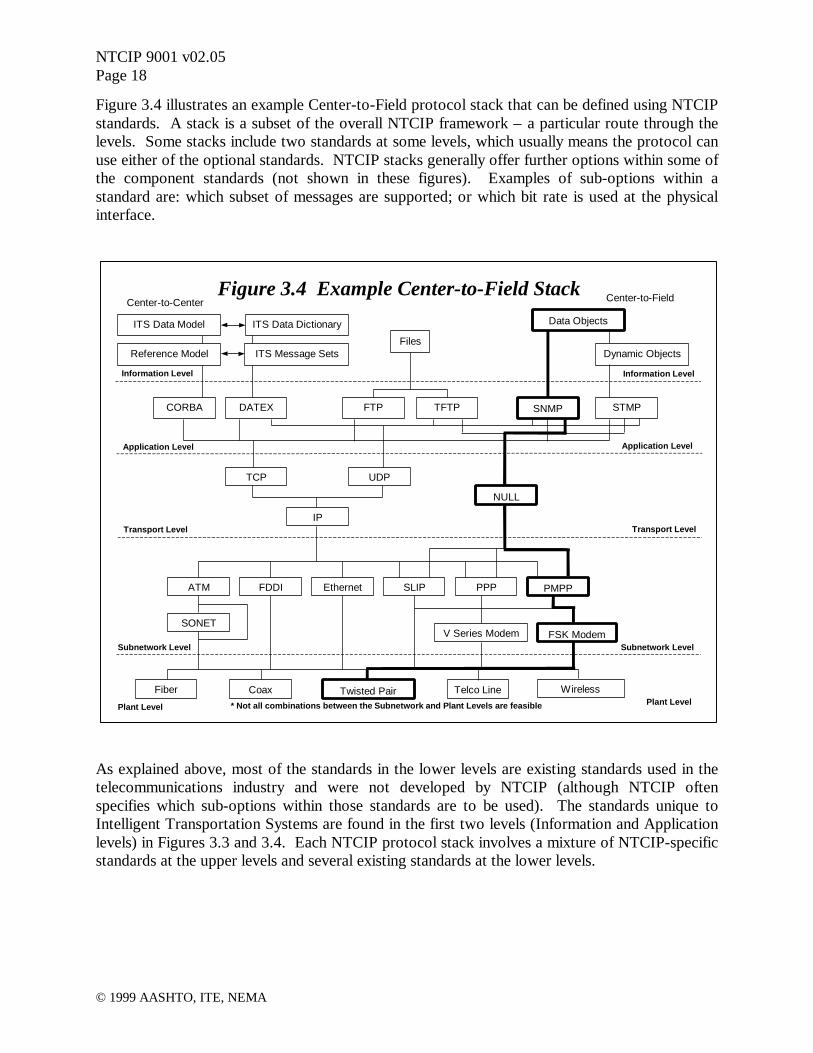
Figure 3.4 illustrates an example Center-to-Field protocol stack that can be defined using NTCIPstandards. A stack is a subset of the overall NTCIP framework – a particular route through thelevels. Some stacks include two standards at some levels, which usually means the protocol canuse either of the optional standards. NTCIP stacks generally offer further options within some ofthe component standards (not shown in these figures). Examples of sub-options within astandard are: which subset of messages are supported; or which bit rate is used at the physicalinterface.
As explained above, most of the standards in the lower levels are existing standards used in thetelecommunications industry and were not developed by NTCIP (although NTCIP oftenspecifies which sub-options within those standards are to be used). The standards unique toIntelligent Transportation Systems are found in the first two levels (Information and Applicationlevels) in Figures 3.3 and 3.4. Each NTCIP protocol stack involves a mixture of NTCIP-specificstandards at the upper levels and several existing standards at the lower levels.
Center-to-Center
Plant LevelPlant Level
Figure 3.4 Example Center-to-Field Stack
SLIP PPP PMPPFDDI Ethernet
Twisted Pair Telco Line Wireless
V Series Modem FSK Modem
Fiber Coax
UDPTCP
IP
NULL
DATEX TFTP SNMP STMPFTPCORBA
Transport Level
Subnetwork Level
Application Level
Information Level
Transport Level
Application Level
Information Level
Subnetwork Level
Dynamic Objects
ITS Data Model
Files
Data Objects
ATM
SONET
ITS Data Dictionary
ITS Message SetsReference Model
Center-to-Field
* Not all combinations between the Subnetwork and Plant Levels are feasible

NTCIP 9001 v02.05Page 19
© 1999 AASHTO, ITE, NEMA
3.7 NTCIP Standards and Protocol Stacks
The first NTCIP standards developed were those intended for center-to-field applications. Thisinvolved a new application level standard called Simple Transportation Management Protocol(STMP), and several sets of new standard data elements called “objects” at the information level.The initial NTCIP center-to-field protocol development also involved specifications for usingtwo existing standards – the Simple Network Management Protocol (SNMP) standard at theapplication level, and the High-level Data Link Control (HDLC) standard at the subnetworklevel.
In 1999, the approach for documenting NTCIP standards and protocol stacks has changed.NTCIP currently defines the options at each level of a protocol stack using “profile” documents.Each profile document specifies one or more standards to be used at a level, and the sub-optionsallowed or required within each of those standards. A profile document typically references oneor more “base standard” documents – documents that contain the specifications for thestandard(s) being called out in the profile. A base standard may be an NTCIP document (if thestandard was developed by NTCIP) or a document developed by any other standardsdevelopment organization. The numbering scheme for NTCIP documents also changed, asshown in the appended list of NTCIP documents.
There are different types of profile documents for the different levels of the stack, as follows:
• Information profiles• Application profiles• Transport profiles• Subnetwork profiles
For a particular application of NTCIP, the user must select (in the procurement specifications)which element(s) are desired at each level – i.e., select from the options called out in one or moreprofile documents for each level. The set of selections for all levels is referred to here as a“protocol stack”. Each NTCIP protocol stack will have different characteristics, and a stack thatworks well for one application or communications environment may not suit another.
Standards that NTCIP has defined, or is in the process of defining, enable protocol stacks thatcan be categorized as follows:
Simple Network Management Protocol (SNMP) – Stacks based on SNMP provide a simple, butbandwidth inefficient, protocol for center-to-field applications, based on the Internet protocol ofthe same name (SNMP). It is suitable only for networks with high bandwidth or low volumes ofmessages. Options are available at the Transport level for routing messages using the InternetProtocol if desired.
Simple Transportation Management Protocol (STMP) – STMP is an extension of SNMP thatallows center-to-field messages to be sent more efficiently using dynamic composite objects.Stacks based on this protocol are suitable for networks with low bandwidth and high volumes of

NTCIP 9001 v02.05Page 20
© 1999 AASHTO, ITE, NEMA
messages, including traffic signal systems. Options are available at the Transport level forrouting messages using the Internet Protocol if desired.
Data Exchange Between Systems (DATEX) – DATEX provides a general purpose center-to-center data exchange protocol stack. It uses pre-defined messages transmitted by the baseInternet protocols (TCP/IP and UDP/IP) in a peer-to-peer network. The base standard at theapplication level is an ISO standard (developed by an NTCIP working group) called DATEX-ASN.
Common Object Request Broker Architecture (CORBA) – A general purpose center-to-centercommunications protocol based on the computing industry standard of the same name. Forobject-oriented systems, it enables a higher degree of integration and some services not providedby DATEX, but may not be suitable for near real-time applications and loosely coupled systems.
The standards that can be used in each of these categories of protocol stacks are highlighted inFigure 3.3.
Two electronic devices will be able to communicate with each other if they use the sameprotocol stack and implement the needed options within that stack.
Section 10.1 contains a complete listing of NTCIP related documents.
3.8 Options and Conformance Levels
In addition to specifying a protocol stack, the system designer must also choose between variousoptions and alternatives available in the selected stack. These options exist in both center-to-center and center-to-field protocol stacks. Major options, such as which protocol(s) to support ateach level in the stack, are sometimes grouped according to conformance levels. Others areindividually selectable. [Most manufacturers and system suppliers typically offer features thatgo beyond the standard. To make use of such features, it is necessary to specify the inclusion ofmanufacturer specific objects or messages when procuring a system.]
Details on options and conformance levels, and how to specify your selection, are presented inlater sections of this Guide.
3.9 Center-to-Center Protocols
NTCIP provides two alternative protocol choices for center-to-center communications, asdiscussed above. One is called DATEX and the other is called CORBA. Two differentprotocols were found necessary to meet the variety of requirements for inter-system dataexchanges. It is feasible to use both protocols in the same network, with some centers acting as abridge, or translator, between the two. The key is in determining where to deploy each protocol.

NTCIP 9001 v02.05Page 21
© 1999 AASHTO, ITE, NEMA
DATEX was designed to provide simple, cost-effective solutions for basic needs. It is especiallywell suited for:
• Systems requiring real-time, fast data transfer (e.g. traffic signal status data)• Systems with limited communications bandwidth but high data transfer load• Systems with infrequent event driven exchanges over dial-up links• Non-object oriented systems
Conversely, CORBA provides several features to support networks connecting object orientedsystems, and assuming sufficient processing power and communications bandwidth are provided,it could be used for all applications between such systems. Object oriented software can take fulladvantage of CORBA and implement it easily, traditional procedural software cannot.
It is expected that most systems will support DATEX, and may initially use it solely. Even ifsome systems in the network are object oriented and use CORBA, they will likely also supportDATEX to allow interfaces with DATEX-only systems and to assist in real-time data exchangeneeds. Over time, as a standardized reference model emerges, new object-oriented systems comeon line, and processing and communications resources are upgraded, more and more systemsmay migrate to CORBA. Non-object-oriented systems that reside in large regions ofinterconnected ITS systems may choose to wrap their interface and provide a CORBA interfaceto leverage CORBA capabilities. These and other implementation issues are discussed in latersections of this Guide.
Center-to-center networks allow each system to request any available information from any or allother systems. Each system can be configured to either accept or reject any request. The “data”sent can be informational or can constitute a “command” to take some action. Consider amessage sent from one traffic signal system to another and containing a signal timing patternnumber. In DATEX for example, depending on the message type, it could represent a commandto implement that timing pattern at a particular traffic signal or group of signals, or it couldrepresent a status report indicating that this timing pattern was just implemented at a particulartraffic signal or group of signals.
In either case, the user can establish standing subscriptions for data if it wants the same data sentrepeatedly. In DATEX, subscriptions can specify that data be sent one-time-only, periodically,or repeatedly on occurrence of some event defined in the subscription. Each subscriptionmessage has a corresponding publication message. Unless the subscription is a one-time request,the data will continue to be automatically “published” repeatedly until the subscription iscancelled, or until a predefined end date specified in the subscription. Using CORBA, a systemcan automatically and dynamically “discover” data available from other systems.
Center-to-center communications require a peer-to-peer network connection between theinvolved computers. This is typically a local area network, a wide area network, or a dial-upconnection. Local area networks typically use agency-owned twisted pair cable or fiber opticcable. Wide area networks typically use commercial telecommunications links such as frame-relay, partial T1 leased lines, packet radio, or leased “virtual private networks”. Dial-upconnections typically use ISDN, V.90 or similar modems over plain-old telephone lines. Any

NTCIP 9001 v02.05Page 22
© 1999 AASHTO, ITE, NEMA
type of communication link can be used, as long as it enables use of the Internet transport androuting protocols (TCP/IP and UDP/IP) and has sufficient bandwidth for the plannedcommunications load (frequency and size of messages to be transmitted).
3.10 Center-to-Field Protocols
NTCIP provides two closely related protocols choices for center-to-field communications. Theseare based on the Simple Network Management Protocol (SNMP) and the Simple TransportationManagement Protocol (STMP). Both of these base protocols use the get/set messaging paradigmused in the Internet’s Simple Network Management Protocol. Both choices use the same basedata objects, as defined in the NEMA TS 3.x series of documents. They differ in the level ofcomplexity to implement and the types of services offered. Table 3.1 summarizes the servicesoffered and implementation requirements.
Table 3.1 SNMP and STMP Comparisons
SNMP STMP
Can send any base object? Yes Yes
Bandwidth Efficiency – inverse of packet overhead Worst Best(uses dynamic composite objects)
Supports routing & dial-up Options Options
Message Set Supported Limited to 13
Ease of implementation Easiest Hardest
The Simple Transportation Management Protocol (STMP) is the most bandwidth efficient optionand includes full support of SNMP for infrequent messaging demands. It includes SNMP as asubset, so that any management system that implements STMP can also communicate with adevice that supports only SNMP. Occasional messages requiring additional security can be sentusing SNMP. The greatest advantage of STMP is its support for dynamic composite objectswhich, combined with a more efficient encoding scheme, dramatically reduce the packetoverhead (relative to SNMP). Dynamic composite objects also enable users to define custommessages that are composed of any number of individual data objects. It is the most flexible andbandwidth efficient option.
Devices that use either the PMPP or Ethernet Subnetwork Level can share the samecommunications line with other devices using the same subnetwork. It doesn’t matter if suchdevices are from different manufacturers or are totally different devices (e.g., a traffic signal anda dynamic message sign). Each device is assigned an address that is unique on that line orchannel. The management system can communicate with any of the devices at any time bysending a message addressed to that device. However, it can communicate with only one of thedevices on the line or channel at a time. Devices can send a message to the management system
NTCIP 9001 v02.05Page 23
© 1999 AASHTO, ITE, NEMA
only when requested to do so by the management system. The NTCIP protocols enablebroadcast messages intended for all devices (e.g., a time clock update). No devices can reply toa broadcast message.
The NTCIP center-to-field protocol stacks can be used in management systems of anyconfiguration or complexity. There are options within each stack to add support for messagerouting via intermediate communications hubs or field masters if needed. However, a particularimplementation of a center-to-field protocol stack may not provide support for such optionsunless specifically requested at the time of procurement.
The communications link can use any medium, such as twisted wire pairs, coaxial cable, opticalfibers, or radio (e.g., narrow band, spread spectrum, microwave). It does not matter whether thecommunications media is agency owned, leased, or dial-up. Multiplexers can be used tocombine multiple channels on one trunk link. Theoretically, any data transmission rate can beused with NTCIP. However, field devices typically support transmission rates in the range of1200 to 19,200 bits per second. The only requirement is that the time for transmission (includingany delay in intermediate relay devices) and the response time in the end device, be reasonableand within the tolerances needed to allow all devices to communicate within the required timeframe. These requirements, together with the bit rate and quantity of information to betransmitted, determine the maximum feasible number of devices on each communicationschannel, as discussed below.
3.11 Communications Infrastructure for Center-to-Field
In planning a center-to-field communications network using NTCIP that involves continuouspolling of field devices (e.g., a traffic signal system or transit fleet AVL system), it is importantto consider the relationship between the following key variables:
• Transmission rate (bit rate)• Transmission method (e.g., full or half duplex, sequential or overlapping)• Transmission delay (including any modem/radio set-up/turn-around time)• Response delay in the field device (time from receipt of request to sending response)• Time between devices or between polling cycles (if needed)• Length of message(s) to be sent (dynamic composite object definitions)• Frequency of each type of message (per second, per minute, per day)• Number of devices sharing the same line or channel• Frequency of communication (e.g., polling period)
The first seven of these variables will determine the total time needed to communicate once witheach device. If this time is then treated as fixed (say T), the number of devices sharing the sameline or channel (say N) and the frequency of communication with each device (say P for pollingperiod, the inverse of frequency) are related by the equation; P = N x T. This is a very simplifiedexplanation of what can be a quite complex design issue that should be addressed early in projectplanning.

NTCIP 9001 v02.05Page 24
© 1999 AASHTO, ITE, NEMA
Although the NTCIP Simple Transportation Management Protocol is designed for use withcommunications channels that use a slow transmission rate (as low as 1200 bits per second), it isnot as bandwidth efficient as most proprietary protocols used in the past. With existingcommunications infrastructure, it may not be possible to maintain the same polling period withthe same number of devices per channel. This is due to the fact that proprietary protocols areoptimized for each manufacturer’s equipment and one or two fixed short messages, whilestandard protocols are designed to accommodate all needs and a wide variety of information andmessages in a multi-vendor environment. However, careful design can usually find a reasonablecompromise between the principal variables. The higher the bandwidth available (bit rate), thefewer the compromises or tradeoffs required. If new communications infrastructure can beprovided, it should allow for additional channels and/or higher transmission rates.
Such implementation issues are discussed in more detail in later sections of this guide.
3.12 Retrofitting Existing Center-to-Field Systems with NTCIP
It may not be feasible to modify old versions of controllers or controller software to make themNTCIP compatible. Constraints such as computing power, memory available, cost ofmodification may well preclude such modifications. If such controllers or software cannot beupgraded or replaced, traffic control systems that continue to make use of older equipment orolder software versions will likely have to continue using the protocols unique tocommunications with those devices. However, current version controllers and software withinthe system may be capable of modification to use NTCIP, and all future versions should beNTCIP compatible. If in doubt, the equipment manufacturer should be contacted and asked ifupgrades for NTCIP compliance are available.
In general, NTCIP and non-NTCIP devices cannot be mixed on the same communicationschannel. Therefore all devices sharing a channel must be upgraded simultaneously. A computeror master that communicates with both NTCIP and non-NTCIP devices will need to use adifferent communications port for NTCIP devices and for non-NTCIP devices, and will need tosupport both protocols. In traditional closed-loop traffic signal systems, the most likely andsimplest solution is to limit each field master to one protocol. Only field masters with NTCIP-compatible controllers would be upgraded to support NTCIP. This avoids the need for fieldmasters to simultaneously support two protocols on two separate ports.
In closed-loop traffic signal systems, the central computer could communicate with field mastersusing a different protocol than that used by the field master to communicate with controllers. Aswith the controller and the field master, the central computer software will need to be modifiedto add support for an NTCIP protocol if NTCIP is to be used for communications with fieldmasters.
Any upgrade of an existing system to add support for NTCIP is probably best designed inconsultation with the system vendor. Each vendor will likely adopt an upgrade strategy that ismost efficient for the majority of its customers. If a particular customer wants a unique

NTCIP 9001 v02.05Page 25
© 1999 AASHTO, ITE, NEMA
arrangement, that customer will probably have to pay the full cost of the software modifications,whereas the cost of the general solution can be spread among many customers.
One approach to the introduction of NTCIP in a center-to-field system is to operate two totallyseparate systems - one NTCIP and one non-NTCIP - during a transition period. Field devicescan gradually be switched over from one to the other as they are replaced or their software isupgraded. This may be the only choice if the current system is quite old and upgrading it forNTCIP is not practical. Such a transition would logically be done as part of a general systemupgrade.
Even if a system continues to use a proprietary protocol, new controllers and masters, or newsoftware packages should include the appropriate NTCIP protocol stack as an option. Somevendors will support both their existing protocols and NTCIP in the same software package.Others will require a change of software to switch from one protocol to the other. Regardless ofhow it is done, the owning agency should ensure that an appropriate NTCIP protocol stack isavailable for future use even if it is not needed immediately. This will maximize the useful lifeof the new equipment and enable introduction of NTCIP at any time in the future without furtherupgrades. It also maximizes options and competition when choosing new equipment, sincedifferent vendors' equipment can be mixed if needed (assuming support is available formanufacturer-specific information).

NTCIP 9001 v02.05Page 26
© 1999 AASHTO, ITE, NEMA
4 PROCURING NTCIP
4.1 Introduction
The purpose of this section is to provide guidance to those who are responsible for developingspecifications for and procuring NTCIP compliant devices and systems. This section is writtenspecifically to target the systems planner/specification writer, or that person responsible forpreparing procurement and system design and specifications for NTCIP systems.
This chapter contains the following sections:
• Procurement Roadmap- Procurement Request- Proposal Initiation- Investigate Issues
- Requirements- How NTCIP Standards Fit Together- Selecting Standards and Conformance Statements- Manufacturer Extensions
- Implementation Alternatives- Other Factors
- Stability of the Standard- Support of Amendments- Agency / Developer Understanding- Certification Process- Performance Issues
- Proposal Submission- Delivery / Acceptance Testing
- Unit Testing- Integration Testing- System Testing
- Maintenance- Design Requirements- Testing Requirements
• Center-to-Field- NTCIP Stack Options- Available Resources for Additional Information- NTCIP Specification Development Examples
- NTCIP Stack for Center-to-Field Traffic Signal Controller- Conformance Group and Data Object Selection for Traffic Signal Controllers- Object Range Values for an Actuated Traffic Signal Controller
• Center-to-Center

NTCIP 9001 v02.05Page 27
© 1999 AASHTO, ITE, NEMA
The NTCIP effort represents a family of open communication standards for ITS deployments.Standardized communication protocols enable Interoperability and Interchangeability and withthis comes an eagerness to implement these standards. Too often, we have seen the desire toimplement these standards overshadow our knowledge of which standards are really needed andhow those standards should be specified.
Systems and equipment procurement specifications sometimes include simply a sentence such as“All components shall be NTCIP compliant,” or “The system shall use NTCIP as thecommunications protocol.” These single statements provide no information to manufacturers orsystems integrators on the type, scope, and functionality of the system or hardware to beimplemented. Specifying detailed requirements for NTCIP is not a trivial task and requires agreat deal of study to develop a set of detailed specifications that will ultimately meet theintended needs. This section is intended to guide the systems planner/specification writerthrough the specification development process, pointing out key considerations along the way,and provide additional understanding of NTCIP when coupled with the information provided inprevious sections.
It has been said on many occasions that there is no exact specification wording that can simplybe copied into procurement documents. The reason for this is that there is no single systemdesign that is standard across the country. Available resources and functionality needs vary fromagency to agency and as a result, system designs vary from agency to agency. Obviously,defining a system that encompasses all the functionality and options that are available would be acostly burden for smaller agencies to bear. And, defining a system with minimal functionalitywould not meet the needs of many larger agencies. Therefore, this section will focus on thepresentation of a process to follow when developing procurement specifications for systems andequipment using NTCIP.
4.2 Procurement Roadmap
There are certain steps that should be taken in any systems procurement project to successfullymeet the intended goals. It is especially critical to follow an orderly procedure when procuringsystems that are intended to meet standards. Figure 4.1 summarizes some of the more importantsteps that should be followed by any organization considering the procurement of NTCIPdevices/software.

NTCIP 9001 v02.05Page 28
© 1999 AASHTO, ITE, NEMA
4.2.1 Procurement Request
The procurement request can take many forms. Devices are often purchased through a low-bidprocess administered by the agency. Software is routinely procured through service orientedcontracts. As such, the specifications and requirements that are made part of the procurementpackage can range from detailed specifications to more general requirements documents. Theprocurement of NTCIP compliant devices and software does not change the normal procurementmethods that most agencies use. Additional steps, however, may need to be added to traditionalprocurement processes for NTCIP related procurements to ensure an adequate understanding ofthe intended requirements and assurance of adherence to the standards and specifications.
4.2.2 Proposal Initiation
There are two alternative approaches that can be used when considering the preparation ofprocurement documents for NTCIP systems and devices. One approach might be for the agencyto solicit a proposal during the procurement process that allows the manufacturer, vendor,developer, or systems integrator to present detailed information on how the intended system or
SelectManufacturer
Extensions
Figure 4.1 Roadmap for Procuring NTCIP
MaintenanceProposal
SubmissionStudy
ImplementationAlternatives
SystemTest
IntegrationTest
Delivery andAcceptance
UnitTest
ProposalInitiation
InvestigateIssues
StudyRequirements
ConsiderOther Factors
Stabilityof Standard
Support ofAmendments
Agency/DeveloperUnderstanding
CertificationProcess
PerformanceRequirements
ProcurementRequest
SelectStandards andConformance
Statements
NTCIP 9001 v02.05Page 29
© 1999 AASHTO, ITE, NEMA
device compliance with NTCIP standards are to be achieved. This method of procurement relieson the preparation of general requirements documents during the initial stages of theprocurement process. At some point thereafter, either during selection or after award, the agencysolicits for approval a detailed proposal from the systems developer or integrator that presentsdetailed information as to which specific standards, conformance groups, data objects, and rangevalues can be provided to meet the procurement requirements. Additionally, any other pertinentinformation should be included. The proposal submission and approval process described heremight be an iterative process, depending on the specific requirements of the agency.
Another method of preparing procurement specifications is the development of detailed NTCIPsystem or device specifications, in addition of any detailed functional specifications. This routerequires extensive knowledge both NTCIP standards and the device or system functionalityneeded to meet the intended needs. Pursuit of this alternative would require the agency to makethe necessary selections at all levels within the NTCIP Framework to determine an NTCIP stackthat will meet their needs. Specific NTCIP standards, conformance groups, data objects, andrange values will need to be identified as well. It should be stressed that this method ofpreparing procurement documents will require expertise in both communications and systemsdesign, in addition to extensive knowledge of the intended device or system functionality.
4.2.3 Investigate Issues
Both the agency and the systems developer or integrator must ensure that there is an adequateunderstanding of the requirements set forth in the procurement request. Some requests to-datehave been very ambiguous, like "The device shall be NTCIP compliant.", others have been verydetailed and precise, and some have even had precise statements that conflicted with each other.Thus, the agency should expect that a systems developer or integrator would first perform aninvestigation to ensure a proper understanding of project needs. This should then be followed byan investigation of how the system may be implemented while recognizing the developmentrisks that may be encountered.
It should be realized that this process often works best in an iterative fashion. This allows theagency and the system developer or integrator to work together in developing a list ofrequirements and a proposal that best matches everyone's needs. However, this is not alwayspossible due to the procurement regulations of some organizations.
4.2.3.1 Requirements
The first aspect of the investigation should be to determine the exact requirements for the system.This will often require expanding the original request. For example, if the procurement requestis simply for an "NTCIP compliant device", the developer must determine what functionality thedevice is supposed to support and then determine what NTCIP options might be appropriate.
An agency should understand that the developer might also need to modify or limit the originalprocurement request in order to meet safety, schedule, or other concerns. For example, the

NTCIP 9001 v02.05Page 30
© 1999 AASHTO, ITE, NEMA
request may be for a signal controller and require "support for the full range of all objects."However, for safety and liability reasons, the developer may want to develop his software tolimit the valid values for the yellow clearance interval to 3.0 to 5.0 seconds. It is important toidentify any such variances from the request as early as possible so that the expectations for theresulting product are properly managed.
The result of this effort should be a detailed requirements document with which both the clientand developer can be satisfied. Additional details of this investigation are given below. As aminimum, the document should address those issues identified throughout this section.
4.2.3.1.1 How NTCIP Standards Fit Together
Ideally, there would only be one NTCIP standard that met everyone's needs. However, realityrequires a large number of options to meet the unique needs of specific sites. For example, someagencies have a large amount of twisted pair copper that they want to continue to use. Otheragencies are installing new systems and want to take advantage of fiber optic cable and othertechnologies. Likewise, some agencies have fairly simple data exchange needs with fielddevices, whereas other centers need to exchange large amounts of information with other centers.The NTCIP accommodates these various needs by providing a suite of standards, each providingunique features.
Figure 4.2 depicts the NTCIP Standards Framework. The framework is based upon five levelsincluding Information, Application, Transport, Subnetwork, and Plant Levels. The middle threeof these five levels loosely relate to the various layers of the seven-layer OSI model. The PlantLevel is included as a reference to show the relationship to field infrastructure. The figure showsall the various standards that reside on each level and represents the various choices that must bemade during the specification development process. The connecting lines represent thecompatibility linkages between the various standards.
• Information Level – Information Profiles define the meaning of data and messages andgenerally deal with ITS information (rather than information about the communicationsnetwork). This is similar to defining a dictionary and phrase list within a language.These standards are above the traditional ISO seven layer stack.
• Application Level – Application Profiles define the rules and procedures for exchanginginformation data. The rules may include definitions of proper grammar and syntax of asingle statement as well as the sequence of allowed statements. This is similar tocombining words and phrases to form a sentence or a complete thought and defining therules for greeting each other and exchanging information. These standards are equivalentto the Session, Presentation and Application Layers of the ISO seven layer stack.
• Transport Level – Transport Profiles define the rules and procedures for exchanging theApplication data between point 'A' and point 'X' on a network. This includes anynecessary routing, message disassembly/re-assembly and network management functions.
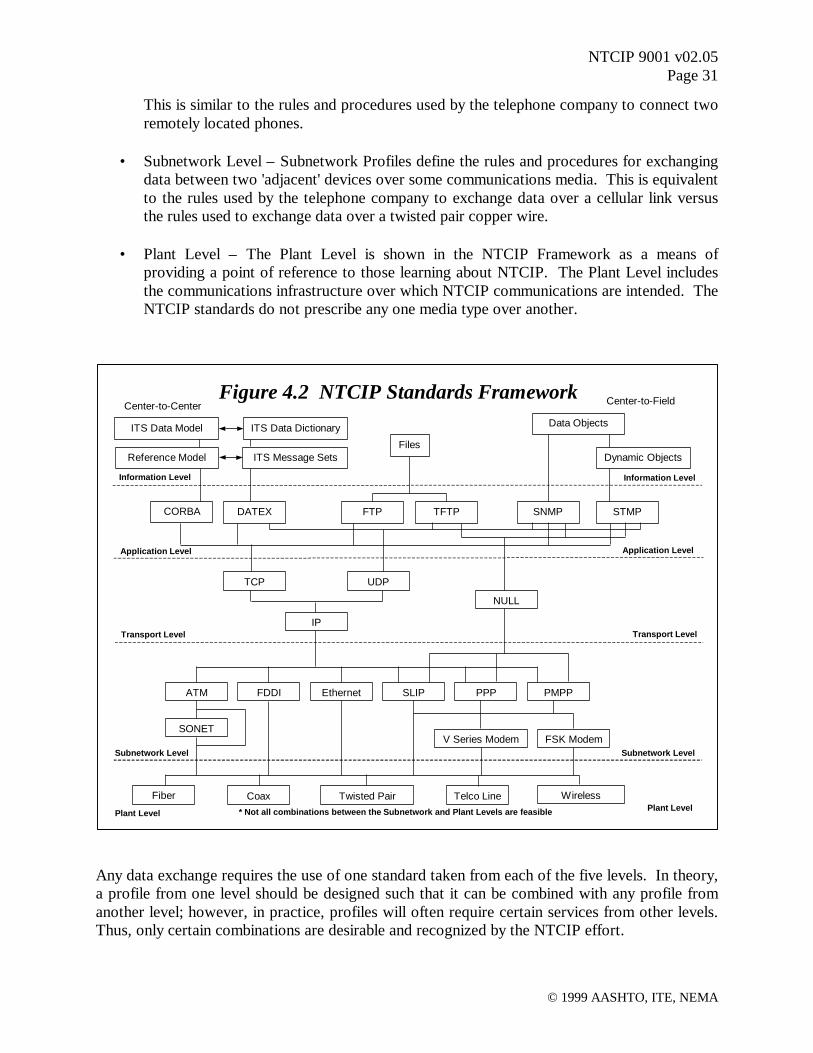
NTCIP 9001 v02.05Page 31
© 1999 AASHTO, ITE, NEMA
This is similar to the rules and procedures used by the telephone company to connect tworemotely located phones.
• Subnetwork Level – Subnetwork Profiles define the rules and procedures for exchangingdata between two 'adjacent' devices over some communications media. This is equivalentto the rules used by the telephone company to exchange data over a cellular link versusthe rules used to exchange data over a twisted pair copper wire.
• Plant Level – The Plant Level is shown in the NTCIP Framework as a means ofproviding a point of reference to those learning about NTCIP. The Plant Level includesthe communications infrastructure over which NTCIP communications are intended. TheNTCIP standards do not prescribe any one media type over another.
Any data exchange requires the use of one standard taken from each of the five levels. In theory,a profile from one level should be designed such that it can be combined with any profile fromanother level; however, in practice, profiles will often require certain services from other levels.Thus, only certain combinations are desirable and recognized by the NTCIP effort.
Center-to-FieldCenter-to-Center
Plant LevelPlant Level
Figure 4.2 NTCIP Standards Framework
SLIP PPP PMPPFDDI Ethernet
Twisted Pair Telco Line Wireless
V Series Modem FSK Modem
Fiber Coax
UDPTCP
IP
NULL
DATEX TFTP SNMP STMPFTPCORBA
Transport Level
Subnetwork Level
Application Level
Information Level
Transport Level
Application Level
Information Level
Subnetwork Level
Dynamic Objects
ITS Data Model
Files
Data Objects
ATM
SONET
ITS Data Dictionary
ITS Message SetsReference Model
* Not all combinations between the Subnetwork and Plant Levels are feasible

NTCIP 9001 v02.05Page 32
© 1999 AASHTO, ITE, NEMA
4.2.3.1.2 Selecting Standards and Conformance Statements
The selection of standards for implementation is largely dependent on the specific requirementsand design of each system. Subsequent sections in this chapter will provide some additionalinsight as to how to select the applicable standards for implementation. As a matter or course,agencies should work closely with systems developers and integrators to determine detailsspecific to particular implementations. One method for doing this is through the use of aproposal response that is part of the procurement process. Essentially, an early deliverable in theprocurement process should be a proposal from the systems developer or integrator showingapplicable details specific to the procurement. The proposal topics should cover the specificstandards to be implemented, applicable conformance groups, applicable data objects and theirassociated range values, and any other information pertinent to the procurement orimplementation. The agency should provide an approval of the proposal prior to proceedingwith device or software development and delivery.
4.2.3.1.3 Manufacturer Extensions
Users, manufacturers, and systems integrators have traditionally implemented functionalitybased upon the needs of the system being implemented. Often, these features and enhancedfunctionality have been implemented in a different manner, depending on the manufacturer, user,or system. As such, there are a variety of alternative methods of performing some functions andproviding some enhanced features.
In many cases the standard may not support all of the features supported by a manufacturer'sdevice or software. The NTCIP has been explicitly designed to allow for innovations and it isrecognized that the NTCIP standards do not currently define standardized objects for everyfeature of every device. Thus, there could be special features or requirements in the procurementthat are not standardized by the NTCIP. If such features are present, then the systems developeror integrator will need to determine precisely how these features will be supported withoutconflicting with the standardized implementations. Usually, this is accomplished by simplydefining additional objects under a developer specific node for the manufacturer specific MIBextensions. It is important that the agency be aware of the use of manufacturer extensions andrequest that the systems developers or integrators clearly identify these in their proposal.
4.2.3.2 Implementation Alternatives
The agency should be aware that systems developers and integrators have a variety of resourcesavailable to implement desired features and the proposal should address these alternatives. Forexample, the developer may be able to acquire off-the-shelf software to minimize the effortrequired to implement the features. A layered design will minimize the effort required tomaintain the code and to implement different profiles in the future. However, these benefits mayimpose other constraints on the system.

NTCIP 9001 v02.05Page 33
© 1999 AASHTO, ITE, NEMA
The NTCIP has used widely recognized standards whenever possible. For example, the NTCIPstandards reference the Transmission Control Protocol (TCP), Internet Protocol (IP), SimpleNetwork Management Protocol (SNMP), Common Object Request Broker Architecture(CORBA), and High Level Data Link Control Protocol (HDLC) standards to name just a few.
In many cases, the private industry has developed off-the-shelf tools to aid system developers inimplementing these protocols. Being aware of what products are available and for what costswill allow the developer to provide a more realistic estimate of development costs. For example,most developers use an off-the-shelf implementation of TCP/IP rather than creating their own.Standards for which there are known products include:
• File Transfer Protocol (FTP)• Trivial File Transfer Protocol (TFTP)• SNMP• CORBA• Data Exchange in ASN.1 (DATEX-ASN)• TCP/IP and UDP/IP• Point-to-Point Protocol (PPP)• Ethernet
While off-the-shelf software can save a considerable amount of development time and greatlysimplify maintenance of the software, it may not always provide the most efficientimplementation. Off-the-shelf software has generally been designed in a very layered fashion foreasy maintenance and fully generic use; however, real-time system performance can frequentlybe improved by violating the rules of a true layered design and by embedding customized codefor a specific purpose. The agency should be aware of the benefits and detriments of eachapproach before determining the development approach and cost estimate.
It should also be recognized that the availability of off-the-shelf tools might affect the selectionof features to be included in the requirements document.
4.2.3.3 Other Factors
There may be a variety of other factors that may need to be considered in order to finalize aproposal. Each of these issues may impact the proposed budget, schedule, and/or scope.Therefore, they should be explicitly addressed in the proposal in order to manage expectations.Without the management of expectations early in the process, a product, which the developerbelieves is compliant, may be perceived to be lacking by the client. A sample of these issues isprovided in the following subsections.

NTCIP 9001 v02.05Page 34
© 1999 AASHTO, ITE, NEMA
4.2.3.3.1 Stability of the Standard
The NTCIP standards are still relatively new and all standards are subject to amendments.Amendments typically result from developers attempting to implement the subject standard andrecognizing either a technical problem with the specification or ambiguous wording. Thus, newstandards are frequently amended to solve these problems and the standards become more andmore stable over time. Requiring the use of unproved standards can be risky and agenciesshould work closely with systems integrators and developers if they intend to pursue earlyimplementation of standards.
4.2.3.3.2 Support of Amendments
Because the standards are relatively new, the agency must consider what will happen if anamendment to the standard is approved during the life of the project. As a general rule, it may bedifficult to require developers to support amendments that are made late in the procurement lifecycle. However, many times, a draft amendment may be present during the initial procurementstages and the agency should expect developer proposals to address the existence of anyamendments or proposed amendments.
4.2.3.3.3 Agency / Developer Understanding
Another factor to consider is whether or not the procurement documents provide realisticexpectations. While the NTCIP provides a standardized interface that is flexible enough to meetvarious needs, it may be more bandwidth intensive than previous systems and/or it may use aslightly different database design. It is important to make sure that there are realisticexpectations at the start of the project in order to ensure that the project will be perceived as asuccess.
4.2.3.3.4 Certification Process
The agency must also consider how the procured devices and software are to be tested andcertified as being NTCIP compliant. While a rigid certification process will undoubtedly providea greater assurance to the client, it will also increase costs. Many agencies perform in-housetesting, or the certification of NTCIP compliance may be outsourced as part of the procurement(e.g., through hiring an independent testing lab).
4.2.3.3.5 Performance Issues
The agency should also realize that the flexibility of NTCIP also comes at the price of a morecomplex system than the industry has traditionally used. Therefore, the system may requiremore sophisticated processors or better communication facilities than traditional systems in orderto achieve the same performance level (e.g., response times, etc.). If the agency overlooks these
NTCIP 9001 v02.05Page 35
© 1999 AASHTO, ITE, NEMA
issues during the early stages of the procurement process, there could be significantimplementation problems or setbacks late in the project in order to provide the necessaryperformance.
4.2.4 Proposal Submission
In order to ensure a thorough understanding of the procurement requirements, the agency shouldrequest that the systems developer or integrator submit a proposal for approval thatacknowledges the various issues addressed in this procurement roadmap. This proposal shouldalso specifically address issues such as conformance statements and range values as appropriate.Additionally, any requirements that are unique to the specific procurement or implementationshould also be addressed in the proposal. The proposal provides an opportunity for both theagency and the systems developer or integrator to form a better understanding of the NTCIPimplementation and reach consensus on issues that might be unique to the specific procurement.
4.2.5 Delivery / Acceptance Testing
Another important aspect of the procurement process is deliver and acceptance testing. Theagency should be aware of any time constraints that might be required for the development ofnew software as a result of implementing a new standard.
Upon delivery, the agency should conduct acceptance testing to ensure that the device orsoftware conforms to the procurement requirements and is compliant with the applicablestandards. The agency should require that acceptance testing be covered in the systemdeveloper’s or integrator’s proposal. It should be realized that the NTCIP is a very complex setof standards and it is impractical to perform comprehensive testing. However, well designed testplans can be produced to provide a high level of confidence for a reasonable cost. In some cases,the agency may want to include any applicable test plans as part of the procurement documents.
In general, there are three levels of testing: unit testing, integration testing, and system testing.
4.2.5.1 Unit Testing
Unit testing focuses on comparing an implementation against the standard. This may beperformed by inspecting the code or with the use of "proven" software to send test messages tothe device. This process should be formalized by documenting a specific test procedure that willbe followed and during the test, the result of each step of the procedure should be recorded.
Unit testing provides a basic level of assurance that a product is compliant to a standard. Manytimes, the test plan will be designed such that the failure of one procedure will provide a clearindication of what problem resides within the implementation; thereby minimizing the cost offinding the 'bug'. A device that fails such a test plan would almost certainly not be able to

NTCIP 9001 v02.05Page 36
© 1999 AASHTO, ITE, NEMA
interoperate with other systems. A device that passes such a test has a reasonable probability ofinteroperating.
4.2.5.2 Integration Testing
Integration testing consists of connecting two or more devices together and having themexchange data. Assuming the individual devices have previously passed a sufficiently designedunit test plan and the two devices support the same features, the devices should integrate togetherfairly easily. However, there are a few problems that may arise during this phase. Examplesinclude two different interpretations of a specific requirement (typically a problem of newerstandards) and problems related to system timing between the two implementations.
In theory, the unit test should be thorough enough to prevent any problems in integration testing;however, the integration testing provides a higher level of confidence that nothing has beenoverlooked.
4.2.5.3 System Testing
A final level of testing is system testing. At this level, each device on the system is integratedtogether to form the final system. This level of testing could identify global problems such asmodem carriers being left on (i.e., preventing other devices from talking) or system timing issues(e.g., too many signals on a channel to maintain a desired once-per-second poll rate).
Once again, in theory, devices that successfully pass unit testing and integration testing shouldpass this system level testing as well, given that the system was properly designed. However, thefinal check is only provided when this system test is performed and it is not infrequent thatproblems arise at this stage.
4.2.6 Maintenance
Agencies should be aware of the fact that procurement requirements may need to addressmaintenance and subsequent device and/or software upgrades. In general, it should berecognized that the NTCIP standards are still relatively new and thus changes may occur to thestandards. Further, as there are relatively few implementations available, ambiguities may stillbe discovered in the standard and the standards may be modified in order to correct theseproblems. Any such change may require a modification to deployed equipment if the equipmentis to maintain compatibility with the new version of the standard. A basic understanding ofrequirements for maintenance and subsequent upgrades should be addressed early during theprocurement process with the systems developer or integrator.

NTCIP 9001 v02.05Page 37
© 1999 AASHTO, ITE, NEMA
4.2.7 Design Requirements
The systems planner/specification writer should consider the various levels of the NTCIPFramework when preparing procurement specifications. Appropriate choices from each of thefive levels that make up the NTCIP Framework will need to be made sometime during either thespecification development process or the procurement process. One alternative that has beenpresented in this section, places much of the burden on the systems developer or integrator toassist in making the appropriate standards selections and presents a mechanism for agencyapproval. Another alternative puts the burden for detailed specification development on theagency.
It is important to understand that if the agency is planning to prepare detailed procurementspecifications for NTCIP compliant systems, there are several issues that must be addressed inorder to satisfy basic specification requirements. These basic requirements consist of making theappropriate choice of standards for each level within the NTCIP Framework. To effectivelymake these selections, there needs to be a good understanding of what resources, like existingcommunications infrastructure and equipment, might be available from an existing system.Additionally, there needs to be a good understanding of what functionality is needed from theNTCIP compliant system. Table 4.1 presents overview of a basic check-list for use in preparingdetailed specifications for NTCIP systems. Detailed procurement specifications will first requireknowledge that is specific to the system implementation, such as infrastructure media;communication, processing, and data needs; and, intended system functionality.
Table 4.1 Procurement Check-List Overview
o Consider specific communications needso Analyze available resourceso Define an entire NTCIP Stack for intended system(s)o Gather appropriate standards for each level within the NTCIP Stacko Determine required Conformance Groupso Determine required Data Elements (objects)o Define realistic Range Values for implementationo Tailor specifications to meet intended needs
The systems planner/specification writer should consider the communication needs and availableresources specific to the system being deployed in order to effectively provide detailedspecifications for an NTCIP compliant system. Important considerations for determiningspecific communications needs include communications data and timing, channel loading, anddevice latency issues. An entire NTCIP Stack should be defined, along with an identification ofstandards required at each level.
The next step in the process would then be to determine the required optional and mandatoryConformance Groups within each standard that are needed to ensure that the intendedfunctionality needs are met. Additionally, realistic Range Values need to be defined for each ofthe data elements (or objects) within each of the Management Information Bases (MIBs), based

NTCIP 9001 v02.05Page 38
© 1999 AASHTO, ITE, NEMA
upon the functional requirements of specific device specifications. Essentially, detailed NTCIPspecifications should be tailored to meet the intended needs of the system implementation.
Procurement specifications should also include information related to hardware and/or devices,systems integration, testing, and device configuration.
4.2.8 Testing Requirements
Testing for NTCIP compliance is a subject that has been on the minds of many of those goingthrough the process of implementing NTCIP. The biggest question that often arises is, How do Iknow that my device is NTCIP compliant? Other concerns include, how to do testing and whattools are available for testing. Testing is an important part of any procurement and should not beoverlooked.
Essentially, testing for NTCIP compliance can take several forms, from the simple perspective ofdetermining if a device will accept objects transmitted using NTCIP to the more complex notionof ensuring that the device provides the appropriate functional response for the message that wasreceived. While it is not the purpose of this document to define functionality or specific testingprocedures, the authors feel that it is important for procuring agencies to rigorously test devicesand systems to ensure NTCIP compliance. Early testing will avoid future heartache when theneed for interoperability or interchangeability arises. Testing for NTCIP compliance will likelyneed to address message structure and content, as well as the appropriate functionality responsesto the messages transmitted.
One tool that is available for use in NTCIP testing is the NTCIP Exerciser. This software toolwas developed for the purpose of testing the ability to transmit and receive NTCIP objects. Thetool is designed to verify the communications process by allowing the user to determine if themessages are in an NTCIP format and are transportable. Functionality testing to determine if theappropriate operations occur as a result of the transmitted message is left to the user and is not afunction of the Exerciser. It should be stressed that the NTCIP Exerciser is simply one tool atthe disposal of testing agencies for use in a comprehensive testing program.
4.3 Center-to-Field
Table 4.2 builds on the previous discussion by expanding on the considerations that should beaddressed during the initial planning and development stages for procurement documents. Theseare items that the systems developer or integrator should provide as part of their proposalsubmission, or in the case of an agency pursuing the detailed specification route these should beaddressed in the procurement documents. The table also points to additional resources that areavailable in further refining detailed specifications.

NTCIP 9001 v02.05Page 39
© 1999 AASHTO, ITE, NEMA
Table 4.2 Procurement Check-List Overview
q Consider specific communications needsq Communications data and timingq Channel loadingq Device latency
q Analyze available resourcesq New system with no existing resourcesq Existing system with available resources
q Define an entire NTCIP Stack for intended system(s)q See Table 4.3
q Gather appropriate standards for each level within the NTCIP Stackq See Table 4.4
q Determine required Conformance Groupsq Mandatoryq Optionalq See specific standards that relate to needed functionality
q Determine required Data Elements (objects)q Mandatoryq Optionalq See specific standards that relate to needed functionality
q Define realistic Range Values for system implementationq See functionality requirementsq See specific standards that relate to needed functionality
q Tailor specifications to meet intended needs
Example 4.1 Example of a Center-to-Field Stack using SNMP
This example shows one possible path through the NTCIP Framework for thecommonly referred to and published Class B Profile. It should be noted that thepreferred terminology for this path is STACK, rather than profile.
Figure 4.3 depicts an example center-to-field NTCIP Stack and is one variation of what waspublished as the Class B Profile. The Stack is shown as it relates to the NTCIP StandardsFramework. The Stack is created by combining appropriate selections from each of theInformation, Application, Transport, Subnetwork, and Plant Levels. The figure shows thechoices at each NTCIP Framework level that are required to create one variation of Class B, as itis now published. For example, the SNMP protocol selection is made at the Application Levelwithin the NTCIP Stack. It should be noted that the trend is moving away from denoting thevarious stacks with alphanumeric characters and is moving towards the designation of specificstandards at each level within the NTCIP Framework. As a result, Class B should be regarded asa legacy term that will ultimately be abandoned in-lieu of an array of specific NTCIP Frameworklevel standards.
The Class B stack that was originally published includes only the Application, Transport, andSubnetwork Levels of the NTCIP Framework. The choices that are offered at the ApplicationLevel include SNMP and STMP. The only choice that is defined for the Transport Level isNULL. The Subnetwork Level option includes Point to Multi-Point, using either EIA 232 orFSK-1200bps modems. The Plant Level is assumed to be agency owned twisted pair wire.

NTCIP 9001 v02.05Page 40
© 1999 AASHTO, ITE, NEMA
In working through this example it is easy to see that these options are quite limited.Extrapolating for all the various system configurations, one can easily see that publishing distinctdocuments for all possible system configurations could be quite exhausting. As a result, thepresentation of NTCIP standards have moved away from the Class Profile presentation andtoward a presentation of standards specific to each Stack layer. This enables the user to betterspecify choices specific to the system being deployed.
4.3.1 NTCIP Stack Options
The Information, Application, Transport, Subnetwork, and Plant Levels of the NTCIPFramework present a variety of options that can be selected to form an NTCIP stack. Table 4.3presents an expanded view of the available center-to-field options that are available at the timethis Guide was prepared.
Center-to-Center
Plant LevelPlant Level
Figure 4.3 Example Center-to-Field Stack
SLIP PPP PMPPFDDI Ethernet
Twisted Pair Telco Line Wireless
V Series Modem FSK Modem
Fiber Coax
UDPTCP
IP
NULL
DATEX TFTP SNMP STMPFTPCORBA
Transport Level
Subnetwork Level
Application Level
Information Level
Transport Level
Application Level
Information Level
Subnetwork Level
Dynamic Objects
ITS Data Model
Files
Data Objects
ATM
SONET
ITS Data Dictionary
ITS Message SetsReference Model
Center-to-Field
* Not all combinations between the Subnetwork and Plant Levels are feasible
NTCIP 9001 v02.05Page 41
© 1999 AASHTO, ITE, NEMA
The Information Level of the NTCIP Framework specifically focuses on the informationalrequirements of the NTCIP device or system to achieve its desired functionality. A thoroughdiscussion of the available Information Level options will be presented later in this section.
In the case of center-to-field, the selection of an appropriate Application Level protocol is animportant consideration. There are two choices for center-to-field protocols, Simple NetworkManagement Protocol (SNMP) that is commonly used in Internet and computer industryapplications. The other choice is the Simple Transportation Management Protocol (STMP)which is a more efficient protocol (in that it reduces the amount of overhead required forcommunications) that allows a user to access multiple objects using a single request.
At the Transport Level the options are essentially comprised of a choice between the use ofrouting protocols or not. A Null Transport Level is used with non-routing protocols. In the caseof routing protocols and additional choice is required between connection-oriented andconnectionless. The Transmission Control Protocol (TCP) is connection-oriented protocol that isused in conjunction with the internetworking protocol simply know as Internet Protocol (IP).The User Datagram Protocol (UDP) is a connectionless protocol that is also used in conjunctionwith the Internet Protocol (IP).
The Subnetwork Level presents a series of networking, point-to-point, and point-to-multi-pointprotocols. ATM, SONET, FDDI, and Ethernet are all examples of broadband networkingprotocol options. SLIP, PPP, and PMPP are also available options at the Subnetwork Level.
The Plant Level of the NTCIP Framework are not specific NTCIP communications standards,but offers a complete relationship to the physical infrastructure that would typically be deployedin modern systems. The Plant Level includes fiber, coax, twisted pair wire, telco lines, andwireless options.
In the cases of protocol selection, it would be advisable to consult equipment and systemmanufacturers for assistance in the selection of the most appropriate supported Protocol(s) thatmeet the overall requirements of the applicable system. STMP should be considered essentialfor traffic signal systems operating over traditional media, but other devices may not need it.
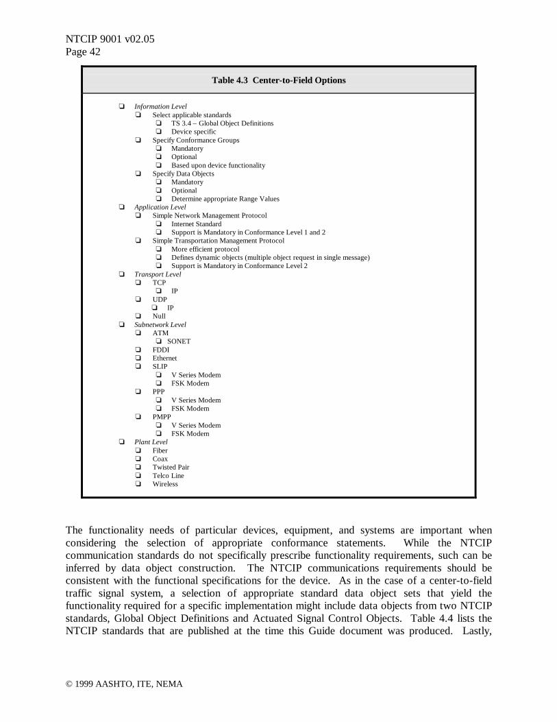
NTCIP 9001 v02.05Page 42
© 1999 AASHTO, ITE, NEMA
Table 4.3 Center-to-Field Options
o Information Levelo Select applicable standards
o TS 3.4 – Global Object Definitionso Device specific
o Specify Conformance Groupso Mandatoryo Optionalo Based upon device functionality
o Specify Data Objectso Mandatoryo Optionalo Determine appropriate Range Values
o Application Levelo Simple Network Management Protocol
o Internet Standardo Support is Mandatory in Conformance Level 1 and 2
o Simple Transportation Management Protocolo More efficient protocolo Defines dynamic objects (multiple object request in single message)o Support is Mandatory in Conformance Level 2
o Transport Levelo TCP
o IPo UDP
o IPo Null
o Subnetwork Levelo ATM
o SONETo FDDIo Etherneto SLIP
o V Series Modemo FSK Modem
o PPPo V Series Modemo FSK Modem
o PMPPo V Series Modemo FSK Modem
o Plant Levelo Fibero Coaxo Twisted Pairo Telco Lineo Wireless
The functionality needs of particular devices, equipment, and systems are important whenconsidering the selection of appropriate conformance statements. While the NTCIPcommunication standards do not specifically prescribe functionality requirements, such can beinferred by data object construction. The NTCIP communications requirements should beconsistent with the functional specifications for the device. As in the case of a center-to-fieldtraffic signal system, a selection of appropriate standard data object sets that yield thefunctionality required for a specific implementation might include data objects from two NTCIPstandards, Global Object Definitions and Actuated Signal Control Objects. Table 4.4 lists theNTCIP standards that are published at the time this Guide document was produced. Lastly,

NTCIP 9001 v02.05Page 43
© 1999 AASHTO, ITE, NEMA
specific range values associated with these data objects would also need to be consistent with thefunctional requirements of the device.
Table 4.4 Currently Published NTCIP Standards
o TS 3.2 – Simple Transportation Management Frameworko TS 3.3 – Class B Profileo TS 3.4 – Global Object Definitionso TS 3.5 – Object Definitions for Actuated Traffic Signal Controller Unitso TS 3.6 – Object Definitions for Dynamic Message Signs*o TS 3.7 – Environmental Sensor Stations*
* publication in progress
Please note that the above Standard number designations refer to those documents that have been published to-date. The numbering scheme for NTCIP documents has been revised and the new designations are shown inSection 9 of this NTCIP Guide.
Upon reviewing standards that might be applicable to a specific implementation, attention shouldbe drawn to the Conformance Statement section of the document. Data objects are arranged ingroupings based upon the data associated with various levels of functionality. Some groups aremandatory and some are optional. Specific data objects within each group may also bemandatory or optional. The specific implementation and functionality requirements will dictatethe selection of appropriate conformance groups and data objects. Once the Data Objects areidentified, a determination of appropriate range values can be assigned to each to represent thedesired level of functionality.
It would be advisable to consult equipment and system manufacturers for assistance in theselection of the most appropriate supported Conformance Groups and Data Objects that meet theoverall requirements of the specific procurement or implementation.
4.3.2 Available Resources for Additional Information
Ultimately, specifying NTCIP does not make life easier for the systems planner and specificationwriter. Detailed specifications must be carefully thought out and a more thorough knowledge ofoperation and functionality is needed early on (in the specification preparation stage) in order toadequately specify equipment and systems that meet the required needs. For these reasons, apreferred method of procurement might be the issuance of a more generalized requirementsdocument that outlines the desired functionality as part of the procurement package and solicit aproposal from the manufacturer, vendor, developer, or integrator addressing the specificimplementation details.
There are a variety of resources available for the user when preparing NTCIP specification. TheNTCIP web site is a valuable tool for reviewing what standards are now available and anyamendments that might be associated with those standards. The various sections of this Guide

NTCIP 9001 v02.05Page 44
© 1999 AASHTO, ITE, NEMA
can provide additional detailed information. In addition, the Standards themselves represent avaluable resource for learning about NTCIP.
Ongoing NTCIP deployments are a valuable resource for learning what works and what doesn’t.There is an ongoing effort to capture some of this information specific to deployments usingNTCIP, in the form of Case Studies. These Case Studies will focus on lessons learned fromrecent deployments.
There are also a variety of companies, groups, and individuals involved in the development ofNTCIP standards that can provide additional information.
4.3.2.1 NTCIP Specification Development Examples
This section is devoted to examples of how the system planner/specification writer would stepthrough a process to develop detailed procurement specifications for NTCIP systems. Examplesare provided for determining an appropriate NTCIP Stack based upon the NTCIP Framework,determining appropriate optional and mandatory conformance groups and objects needed toachieve a desired functionality, and determining the range values that might be needed for aspecific implementation.
4.3.2.1.1 NTCIP Stack for Center-to-Field Traffic Signal Controller
Example 4.1 An appropriate NTCIP Stack is needed for a typical traffic signalcontroller application. In this example, the controller is to be located in a fieldcabinet and is one device on a multi-drop communication channel. The centraltransportation management system constantly communicates directly to the trafficsignal controller(s) over agency owned twisted wire pair cable.
The system planner/specification writer can start by determining the appropriate selections foreach level using the NTCIP Framework, as shown in Table 4.5. It is a given that an agencyowned twisted wire pair communications plant will provide the physical infrastructure forCenter-to-Field communications. The selection at the Plant Level should reflect the selection oftwisted wire pair cable.
The selections made at the Transport and Subnetwork Levels can now be made based upon thetype of communications desired between the central transportation management system and thefield traffic signal controller(s). In this example, a dedicated point-to-multipointcommunications link without routing through higher level devices is the desired alternative. Assuch, the selections of PMPP and FSK Modem can be made at the Subnetwork Level. And, theselection of Null can be made at the Transport Level.
For the appropriate selections at the Application Level the system planner/specification writer isreferred to the NTCIP documents describing the Simple Transportation Management Framework(STMF). The Simple Transportation Management Framework document describes two

NTCIP 9001 v02.05Page 45
© 1999 AASHTO, ITE, NEMA
conformance levels. The original document has been amended to reflect the use of the followingprotocols:
• Conformance Level 1- Simple Network Management Protocol (SNMP)
• Conformance Level 2- Simple Network Management Protocol (SNMP)- Simple Transportation Management Protocol (STMP)
SNMP is a commonly used Internet Standard that is very well supported. STMP is a moreefficient protocol for use by the transportation industry that allows the use of dynamic objects.The preferred selection at the Application Level for traffic signal systems is STMP because ofthe low data rates that are common to most traffic systems.
The selection of Information Level standards, conformance groups, and data objects is basedupon the desired functionality of the system being implemented. In the case of this examplewhere a traffic signal system is being implemented, the system planner/specification writer willneed to look specifically at the requirements of TS 3.5 – Object Definitions for Actuated TrafficSignal Controller Units standard for specific conformance criteria and data objects.Additionally, the TS 3.4 – Global Object Definitions standard defines a series of cross-cuttingdata objects for configuration, database management, time management, timebase eventschedules, reports, STMP, and PMPP. As a result, standards for both Global Object Definitionsand Actuated Signal Control will be needed to achieve the desired level of functionality. Thesestandards define a series of optional and mandatory conformance groups and data objects. Theappropriate selection criteria for these optional and mandatory conformance groups and dataobjects will be the subject of subsequent examples.

NTCIP 9001 v02.05Page 46
© 1999 AASHTO, ITE, NEMA
Table 4.5 NTCIP Framework Example for a Center-to-Field Traffic Signal Controller
o Information Levelo Select applicable standards
o TS 3.4 – Global Object Definitionso Device specific
o TS 3.5 – Object Definitions for Actuated Traffic Signal Controller Units (ASC)o Specify Conformance Groups
o Mandatoryo Optionalo Based upon device functionality
o Specify Data Objectso Mandatoryo Optional
o Determine appropriate Range Valueso Application Level
o Simple Network Management Protocolo Simple Transportation Management Protocol
o Transport Levelo TCP
o IPo UDP
o IPo Null
o Subnetwork Levelo ATM
o SONETo FDDIo Etherneto SLIP
o V Series Modemo FSK Modem
o PPPo V Series Modemo FSK Modem
o PMPPo V Series Modemo FSK Modem
o Plant Levelo Fibero Coaxo Twisted Pairo Telco Lineo Wireless
4.3.2.1.2 Conformance Group and Data Object Selection for Traffic SignalControllers
Example 4.2 An appropriate selection of conformance groups and data objectsare needed for a typical traffic signal controller application. In this example, thecontroller will be based upon the NEMA TS-2-Type2 Actuated Traffic Controllerstandards. The Type2 NEMA controller is one that is backwards compatible tothe NEMA TS-1 Traffic Controller Cabinets with the MS A, B, and C connectors.
The NEMA TS 2 – 1998 Standard for Traffic Controller Assemblies describes a functionalspecification for traffic controller assemblies, including the controller unit, malfunctionmanagement unit, terminals and facilities, auxiliary devices, cabinet, and bus interface unit. The

NTCIP 9001 v02.05Page 47
© 1999 AASHTO, ITE, NEMA
NEMA TS 2-1998 also incorporates the NTCIP standards that relate to traffic signal controllers.The notable NTCIP standards that are referenced are the TS 3.4 – Global Object Definitions andTS 3.5 – Object Definitions for Actuated Traffic Signal Controller Units.
NEMA TS 2 – 1998 describes traffic signal controllers in terms of being either Actuated orPretimed. Also, there are two interface options cited as Type 1 and Type 2. The Type 1interface is a new performance based standard using serial communications and the Type 2interface utilizes the MS A, B, and C connectors to provide backwards compatibility to TS – 1style cabinets.
Table 4.6 Global Object Definitions Conformance Table
NEMATS 2 (A2N)
M – MandatoryO – Optional
Conformance Group/Object Reference ConformanceRequirement
Level 1 Level 2Configuration
globalSetIDParameterglobalMaxModulesglobalModuleTable
moduleNumbermoduleDeviceNodemoduleMakemoduleModelmoduleVersionmoduleType
TS 3.4TS 3.4TS 3.4TS 3.4TS 3.4TS 3.4TS 3.4TS 3.4TS 3.4TS 3.4
Mandatory GroupOptional
MandatoryMandatoryMandatoryMandatoryMandatoryMandatoryMandatoryMandatory
MOMMMMMMMM
MMMMMMMMMM
Database ManagementdBCreationTransactiondBErrorTypedBErrorIDdBTransactionIDdBMakeID
TS 3.4TS 3.4TS 3.4TS 3.4TS 3.4TS 3.4
Optional GroupMandatoryMandatoryMandatoryMandatoryOptional
OOOOOO
MMMMMM
Time ManagementglobalTimeglobalDaylightSaving
TS 3.4TS 3.4TS 3.4
Optional GroupMandatoryMandatory
OOO
MMM
Timebase Event SchedulemaxTimeBaseScheduleEntriestimeBaseScheduleTable
timeBaseScheduleNumbertimeBaseScheduleMonthtimeBaseScheduleDaytimeBaseScheduleDatetimeBaseScheduleDayPlan
maxDayPlansmaxDayPlanEventstimeBaseDay PlanTable
dayPlanNumberdayPlanEventNumberdayPlanHourdayPlanMinutedayPlanActionNumberOIDdayPlanStatus
TS 3.4TS 3.4TS 3.4TS 3.4TS 3.4TS 3.4TS 3.4TS 3.4TS 3.4TS 3.4TS 3.4TS 3.4TS 3.4TS 3.4TS 3.4TS 3.4TS 3.4
Optional GroupMandatoryMandatoryMandatoryMandatoryMandatoryMandatoryMandatoryMandatoryMandatoryMandatoryMandatoryMandatoryMandatoryMandatoryMandatoryMandatory
OOOOOOOOOOOOOOOOO
MMMMMMMMMMMMMMMMM

NTCIP 9001 v02.05Page 48
© 1999 AASHTO, ITE, NEMA
Table 4.6 Global Object Definitions Conformance Table
NEMATS 2 (A2N)
M – MandatoryO – Optional
Conformance Group/Object Reference ConformanceRequirement
Level 1 Level 2Report
maxEventLogConfigseventLogConfigTable
eventConfigIDeventConfigClasseventConfigModeeventConfigCompareValueeventConfigCompareValue2eventConfigCompareOIDeventConfigLogOIDeventConfigAction
maxEventLogSizeeventLogTable
eventLogClasseventLogNumbereventLogIDeventLogTimeeventLogValue
maxEventClasseseventClassTable
eventClassNumbereventClassLimiteventClassClearTimeEventClassDescriptioneventClassNumRowsInLog
TS 3.4TS 3.4TS 3.4TS 3.4TS 3.4TS 3.4TS 3.4TS 3.4TS 3.4TS 3.4TS 3.4TS 3.4TS 3.4TS 3.4TS 3.4TS 3.4TS 3.4TS 3.4TS 3.4TS 3.4TS 3.4TS 3.4TS 3.4TS 3.4TS 3.4
Optional GroupMandatoryMandatoryMandatoryMandatoryMandatoryMandatoryMandatoryMandatoryOptionalOptional
MandatoryMandatoryMandatoryMandatoryMandatoryMandatoryMandatoryMandatoryMandatoryMandatoryMandatoryMandatoryOptional
Mandatory
OOOOOOOOOOOOOOOOOOOOOOOOO
MMMMMMMMMMMMMMMMMMMMMMMMM
STMPdynamicObjectPersistence
TS 3.4TS 3.4
Optional GroupMandatory
OO
MM
PMPPmaxGroupAddresseshdlcGroupAddressTable
hdlcGroupAddressIndexhdlcGroupAddress
TS 3.4TS 3.4TS 3.4TS 3.4TS 3.4
Optional GroupMandatoryMandatoryMandatoryMandatory
OOOOO
MMMMM
Tables 4.6 and 4.7 show how the NTCIP group and data object conformance statements relate tothe NEMA TS 2 – 1998 Standard for Traffic Controller Assemblies. The Level 1 actuated TS 2traffic controller is intended to support only the mandatory NTCIP objects from TS 3.4 – GlobalObject Definitions and TS 3.5 – Actuated Signal Control. The mandatory objects of these twoNTCIP standards to not address the advanced functions relative to coordination, time base,preemption, system control, overlaps, or the TS 2 port 1. A user requesting Level 1 conformanceshould not expect these features unless the user specification includes a definition of additionalconformance groups from the standard, or defines and lists specific alternates. A user specifyingLevel 2 conformance is requesting that all of the mandatory and most of the optional data objectswithin the NTCIP standards TS 3.4 – Global Object Definitions and TS 3.5 – Actuated SignalControl be supported.

NTCIP 9001 v02.05Page 49
© 1999 AASHTO, ITE, NEMA
Table 4.7 Actuated Traffic Signal Controller Unit Object Definitions Conformance Table
NEMATS 2 (A2N)
M – MandatoryO – OptionalConformance Group/Object Reference Conformance
Requirement
Level 1 Level 2
Configuration TS 3.4 Mandatory Group M M
Database Management TS 3.4 Optional Group O M
Time Management TS 3.4 Optional Group O M
Timebase Event Schedule TS 3.4 Optional Group O M
Report TS 3.4 Optional Group O M
STMP TS 3.4 Optional Group O M
PMPP TS 3.4 Optional Group O MPhase
maxPhasesphaseTable
phaseNumberphaseWalkphasePedestrianClearphaseMinimumGreenphasePassagephaseMaximum1phaseMaximum2phaseYellowChagephaseRedClearphaseRedRevertphaseAddedInitialphaseMaximumInitialphaseTimeBeforeReductionphaseCarsBeforeReductionphaseTimeToReducephaseReduceByphaseMinimumGapphaseDynamicMaxLimitphaseDynamicMaxStepphaseStartupphaseOptionsphaseRingphaseConcurrency
maxPhaseGroupsphaseStatusGroupTable
phaseStatusGroupNumberphaseStatusGroupRedsphaseStatusGroupYellowsphaseStatusGroupGreensphaseStatusGroupDontWalksphaseStatusGroupPedClearsphaseStatusGroupWalksphaseStatusGroupVehCallsphaseStatusGroupPedCallsphaseStatusGroupPhaseOnsphaseStatusGroupPhaseNexts
phaseControlGroupTablephaseControlGroupNumberphaseControlGroupPhaseOmitphaseControlGroupPedOmitphaseControlGroupHoldphaseControlGroupForceOffphaseControlGroupVehCallphaseControlGroupPedCall
TS 3.5TS 3.5TS 3.5TS 3.5TS 3.5TS 3.5TS 3.5TS 3.5TS 3.5TS 3.5TS 3.5TS 3.5TS 3.5TS 3.5TS 3.5TS 3.5TS 3.5TS 3.5TS 3.5TS 3.5TS 3.5TS 3.5TS 3.5TS 3.5TS 3.5TS 3.5TS 3.5TS 3.5TS 3.5TS 3.5TS 3.5TS 3.5TS 3.5TS 3.5TS 3.5TS 3.5TS 3.5TS 3.5TS 3.5TS 3.5TS 3.5TS 3.5TS 3.5TS 3.5TS 3.5TS 3.5TS 3.5
Mandatory GroupMandatoryMandatoryMandatoryMandatoryMandatoryMandatoryMandatoryMandatoryMandatoryMandatoryMandatoryOptional
MandatoryMandatoryMandatoryOptional
MandatoryMandatoryMandatoryOptionalOptional
MandatoryMandatoryMandatoryMandatoryMandatoryMandatoryMandatoryMandatoryMandatoryMandatoryMandatoryMandatoryMandatoryMandatoryMandatoryMandatoryMandatoryOptional
MandatoryMandatoryMandatoryMandatoryOptional
MandatoryMandatory
MMMMMMMMMMMMOMMMOMMMOOMMMMMMMMMMMMMMMMMOOOOOOOO
MMMMMMMMMMMMOMMMOMOMOOMMMMMMMMMMMMMMMMMMMMMMOMM

NTCIP 9001 v02.05Page 50
© 1999 AASHTO, ITE, NEMA
Table 4.7 Actuated Traffic Signal Controller Unit Object Definitions Conformance Table
NEMATS 2 (A2N)
M – MandatoryO – OptionalConformance Group/Object Reference Conformance
Requirement
Level 1 Level 2
DetectormaxVehicleDetectorsvehicleDetectorTable
vehicleDetectorNumbervehicleDetectorOptionsvehicleDetectorCallPhasevehicleDetectorSwitchPhasevehicleDetectorDelayvehicleDetectorExtendvehicleDetectorQueueLimitvehicleDetectorNoActivityvehicleDetectorMaxPresencevehicleDetectorErraticCountsvehicleDetectorFailTimevehicleDetectorAlarmsvehicleDetectorReportedAlarmsvehicleDetectorReset
maxVehicleDetectorStatusGroupsvehicleDetectorStatusGroupTablevehicleDetectorStatusGroupNumbervehicleDetectorStatusGroupActivevehicleDetectorStatusGroupAlarmsmaxPedestrianDetectorspedestrianDetectorTable
pedestrianDetectorNumberpedestrianDetectorCallPhasepedestrianDetectorNoActivitypedestrianDetectorMaxPresencepedestrianDetectorErraticCountspedestrianDetectorAlarms
TS 3.5TS 3.5TS 3.5TS 3.5TS 3.5TS 3.5TS 3.5TS 3.5TS 3.5TS 3.5TS 3.5TS 3.5TS 3.5TS 3.5TS 3.5TS 3.5TS 3.5TS 3.5TS 3.5TS 3.5TS 3.5TS 3.5TS 3.5TS 3.5TS 3.5TS 3.5TS 3.5TS 3.5TS 3.5TS 3.5
Mandatory GroupMandatoryMandatoryMandatoryMandatoryMandatoryMandatoryMandatoryMandatoryOptional
MandatoryMandatoryMandatoryOptional
MandatoryOptional
MandatoryMandatoryMandatoryMandatoryMandatoryMandatoryMandatoryMandatoryMandatoryMandatoryMandatoryMandatoryMandatoryMandatory
MMMMMMMMMOMMMOMOMMMMMMMMMMMMMM
MMMMMMMMMMMMMMMMMMMMMMMMMMMMMM
Volume Occupancy ReportvolumeOccupancySequencevolumeOccupancyPeriodactiveVolumeOccupancyDetectorsvolumeOccupancyTable
detectorVolumedetectorOccupancy
TS 3.5TS 3.5TS 3.5TS 3.5TS 3.5TS 3.5TS 3.5
Optional GroupMandatoryMandatoryMandatoryMandatoryMandatoryMandatory
OOOOOOO
MMMMMMM
UnitunitStartUpFlashunitAutoPedestrianClearunitBackupTimeunitRedRevertunitControlStatusunitFlashStatusunitAlarmStatus2unitAlarmStatus1shortAlarmStatusunitControlmaxAlarmGroupsalarmGroupTable
alarmGroupNumberalarmGroupState
TS 3.5TS 3.5TS 3.5TS 3.5TS 3.5TS 3.5TS 3.5TS 3.5TS 3.5TS 3.5TS 3.5TS 3.5TS 3.5TS 3.5TS 3.5
Optional GroupMandatoryMandatoryMandatoryMandatoryMandatoryMandatoryMandatoryMandatoryMandatoryMandatoryOptional
MandatoryMandatoryMandatory
OOOOOOOOOOOOOOO
MMMMMMMMMMMMMMM
Special FunctionmaxSpecialFunctionOutputsspecialFunctionOutputTable
specialFunctionOutputNumberspecialFunctionOutputState
TS 3.5TS 3.5TS 3.5TS 3.5TS 3.5
Optional GroupMandatoryOptional
MandatoryMandatory
OOOOO
MMMMM

NTCIP 9001 v02.05Page 51
© 1999 AASHTO, ITE, NEMA
Table 4.7 Actuated Traffic Signal Controller Unit Object Definitions Conformance Table
NEMATS 2 (A2N)
M – MandatoryO – OptionalConformance Group/Object Reference Conformance
Requirement
Level 1 Level 2
CoordinationcoordOperationalModecoordCorrectionModecoordMaximumModecoordForceModemaxPatternspatternTableTypepatternTable
patternNumberpatternCycleTimepatternOffsetTimepatternSplitNumberpatternSequenceNumber
maxSplitssplitTable
splitNumbersplitPhasesplitTimesplitModesplitCoordPhase
coordPatternStatuslocalFreeStatuscoordCycleStatuscoordSyncStatussystemPatternControlsystemSyncControl
TS 3.5TS 3.5TS 3.5TS 3.5TS 3.5TS 3.5TS 3.5TS 3.5TS 3.5TS 3.5TS 3.5TS 3.5TS 3.5TS 3.5TS 3.5TS 3.5TS 3.5TS 3.5TS 3.5TS 3.5TS 3.5TS 3.5TS 3.5TS 3.5TS 3.5TS 3.5
Optional GroupMandatoryMandatoryMandatoryMandatoryMandatoryMandatoryMandatoryMandatoryMandatoryMandatoryMandatoryMandatoryMandatoryMandatoryMandatoryMandatoryMandatoryMandatoryMandatoryMandatoryMandatoryMandatoryMandatoryMandatoryMandatory
OOOOOOOOOOOOOOOOOOOOOOOOOO
MMMMMMMMMMMMMMMMMMMMMMMMMM
Time BaseTime Management Conformance Group
timebasePatternSyncmaxTimebaseAscActionstimebaseAscActionTable
timebaseAscActionNumbertimebaseAscActionPattern
timebaseAscActionAuxillaryFunctiontimebaseAscActionSpecialFunctiontimebaseAscActionStatus
TS 3.5TS 3.4TS 3.5TS 3.5TS 3.5TS 3.5TS 3.5TS 3.5TS 3.5TS 3.5
Optional GroupMandatoryMandatoryMandatoryMandatoryMandatoryMandatoryMandatoryMandatoryMandatory
OOOOOOOOOO
MMMMMMMMMM
PreemptmaxpreemptspreemptTable
preemptNumberpreemptControlpreemptLinkpreemptDelaypreemptMinimumDurationpreemptMinimumGreenpreemptMinimumWalkpreemptEnterPedClearpreemptTrackGreenpreemptDwellGreenpreemptMaximumPresencepreemptTrackPhasepreemptDwellPhasepreemptDwellPedpreemptExitPhasepreemptState
preemptControlTablepreemptControlNumberpreemptControlState
TS 3.5TS 3.5TS 3.5TS 3.5TS 3.5TS 3.5TS 3.5TS 3.5TS 3.5TS 3.5TS 3.5TS 3.5TS 3.5TS 3.5TS 3.5TS 3.5TS 3.5TS 3.5TS 3.5TS 3.5TS 3.5TS 3.5
Optional GroupMandatoryMandatoryMandatoryMandatoryMandatoryMandatoryMandatoryOptionalOptionalOptional
MandatoryMandatoryMandatoryMandatoryMandatoryOptional
MandatoryOptionalOptional
MandatoryMandatory
OOOOOOOOOOOOOOOOOOOOOO
MMMMMMMMMMMMMMMMOMMMMM
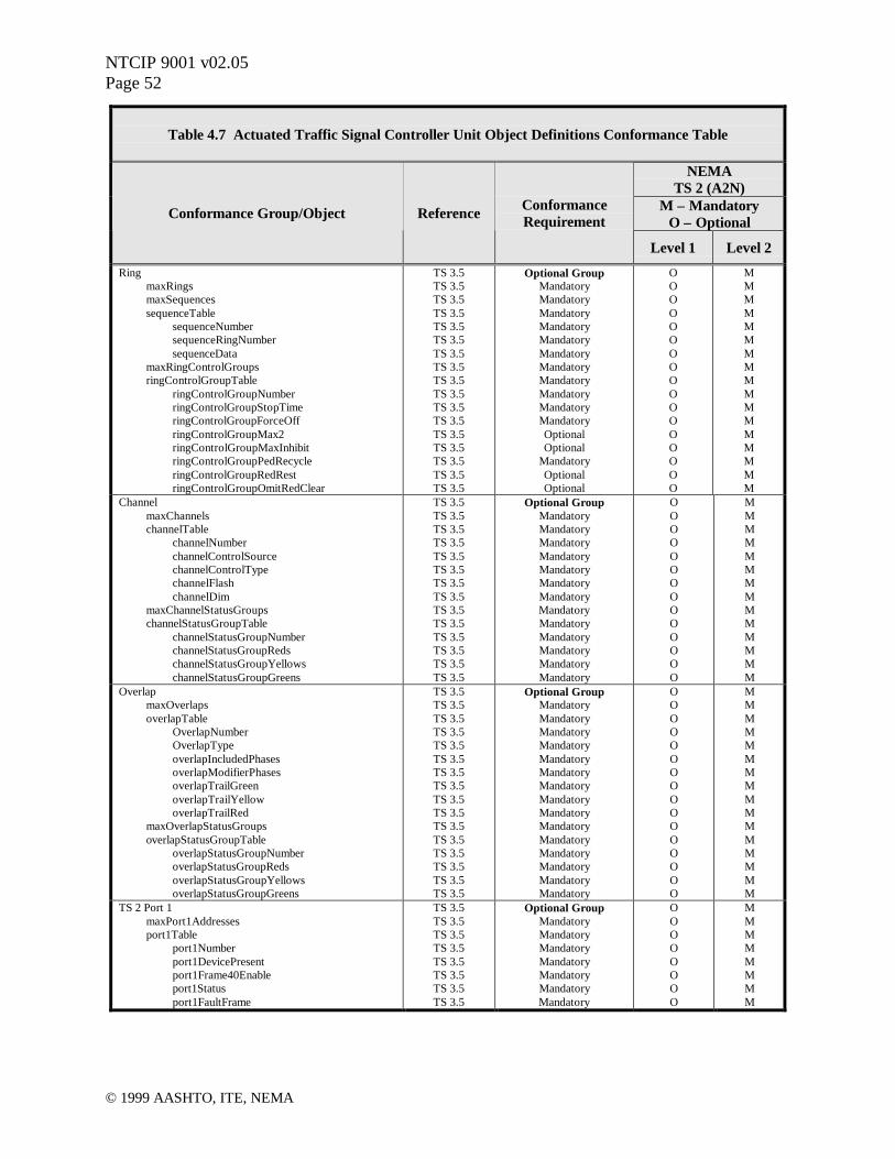
NTCIP 9001 v02.05Page 52
© 1999 AASHTO, ITE, NEMA
Table 4.7 Actuated Traffic Signal Controller Unit Object Definitions Conformance Table
NEMATS 2 (A2N)
M – MandatoryO – OptionalConformance Group/Object Reference Conformance
Requirement
Level 1 Level 2
RingmaxRingsmaxSequencessequenceTable
sequenceNumbersequenceRingNumbersequenceData
maxRingControlGroupsringControlGroupTable
ringControlGroupNumberringControlGroupStopTimeringControlGroupForceOffringControlGroupMax2ringControlGroupMaxInhibitringControlGroupPedRecycleringControlGroupRedRestringControlGroupOmitRedClear
TS 3.5TS 3.5TS 3.5TS 3.5TS 3.5TS 3.5TS 3.5TS 3.5TS 3.5TS 3.5TS 3.5TS 3.5TS 3.5TS 3.5TS 3.5TS 3.5TS 3.5
Optional GroupMandatoryMandatoryMandatoryMandatoryMandatoryMandatoryMandatoryMandatoryMandatoryMandatoryMandatoryOptionalOptional
MandatoryOptionalOptional
OOOOOOOOOOOOOOOOO
MMMMMMMMMMMMMMMMM
ChannelmaxChannelschannelTable
channelNumberchannelControlSourcechannelControlTypechannelFlashchannelDim
maxChannelStatusGroupschannelStatusGroupTable
channelStatusGroupNumberchannelStatusGroupRedschannelStatusGroupYellowschannelStatusGroupGreens
TS 3.5TS 3.5TS 3.5TS 3.5TS 3.5TS 3.5TS 3.5TS 3.5TS 3.5TS 3.5TS 3.5TS 3.5TS 3.5TS 3.5
Optional GroupMandatoryMandatoryMandatoryMandatoryMandatoryMandatoryMandatoryMandatoryMandatoryMandatoryMandatoryMandatoryMandatory
OOOOOOOOOOOOOO
MMMMMMMMMMMMMM
OverlapmaxOverlapsoverlapTable
OverlapNumberOverlapTypeoverlapIncludedPhasesoverlapModifierPhasesoverlapTrailGreenoverlapTrailYellowoverlapTrailRed
maxOverlapStatusGroupsoverlapStatusGroupTable
overlapStatusGroupNumberoverlapStatusGroupRedsoverlapStatusGroupYellowsoverlapStatusGroupGreens
TS 3.5TS 3.5TS 3.5TS 3.5TS 3.5TS 3.5TS 3.5TS 3.5TS 3.5TS 3.5TS 3.5TS 3.5TS 3.5TS 3.5TS 3.5TS 3.5
Optional GroupMandatoryMandatoryMandatoryMandatoryMandatoryMandatoryMandatoryMandatoryMandatoryMandatoryMandatoryMandatoryMandatoryMandatoryMandatory
OOOOOOOOOOOOOOOO
MMMMMMMMMMMMMMMM
TS 2 Port 1maxPort1Addressesport1Table
port1Numberport1DevicePresentport1Frame40Enableport1Statusport1FaultFrame
TS 3.5TS 3.5TS 3.5TS 3.5TS 3.5TS 3.5TS 3.5TS 3.5
Optional GroupMandatoryMandatoryMandatoryMandatoryMandatoryMandatoryMandatory
OOOOOOOO
MMMMMMMM

NTCIP 9001 v02.05Page 53
© 1999 AASHTO, ITE, NEMA
4.3.2.1.3 Object Range Values for an Actuated Traffic Signal Controller
Example 4.3 An appropriate selection of range values are needed for a typicaltraffic signal controller application. In this example, the controller will be an 8 –Phase controller based upon the NEMA TS-2-Type2 Actuated Traffic Controllerstandards.
As in Example 4.2, reference is made to the NEMA TS 2 – 1998 Standard for Traffic ControllerAssemblies. The NEMA TS 2 – 1998 standard provides a listing of minimum NTCIP dataobject range values to be supported by the compliant traffic signal controller.
Table 4.8 shows a typical data object from the NTCIP TS 3.5 – Actuated Signal Controlstandard. The data object shown is the Maximum Number of Phases from the mandatory PhaseParameters conformance group. The Maximum Phases data object has a status of mandatory.The range value of this data object is denoted as integer values from 0 to 255. This means thatthe device may support any value within that range. Additionally, the data object indicates thatthis is a read-only object, where writing a new value is prohibited. Also, included in the dataobject is a description of what this object means.
Table 4.8 Sample Actuated Traffic Signal Controller Data Object
Phase Parameters Conformance Group – Maximum Phases
maxPhases OBJECT-TYPESYNTAX INTEGER (0..255)ACCESS read-onlySTATUS mandatoryDESCRIPTION
“The Maximum Number of Phases this Actuated ControllerUnit supports. This object indicates the maximum rows whichshall appear in the phaseTable object.”
::={phase1}
Table 4.9 shows all of the minimum ranges values that are defined as part of the NEMA TS 2 –1998 Traffic Controller Assembly Standard. The range values shown are based upon theminimum functionality requirements of the NEMA standard. In the case of the MaximumPhases value, we can see that the minimum range value to be supported is 8. The NEMAstandard requires a minimum of 8 phases to meet the functionality requirements of the NEMATS 2 – 1998 standard. As such, the value to be communicated using NTCIP for the MaximumNumber of Phases would be 8. Similarly, other range values can be related to the level offunctionality that is either required by specification or provided by the manufacturer.
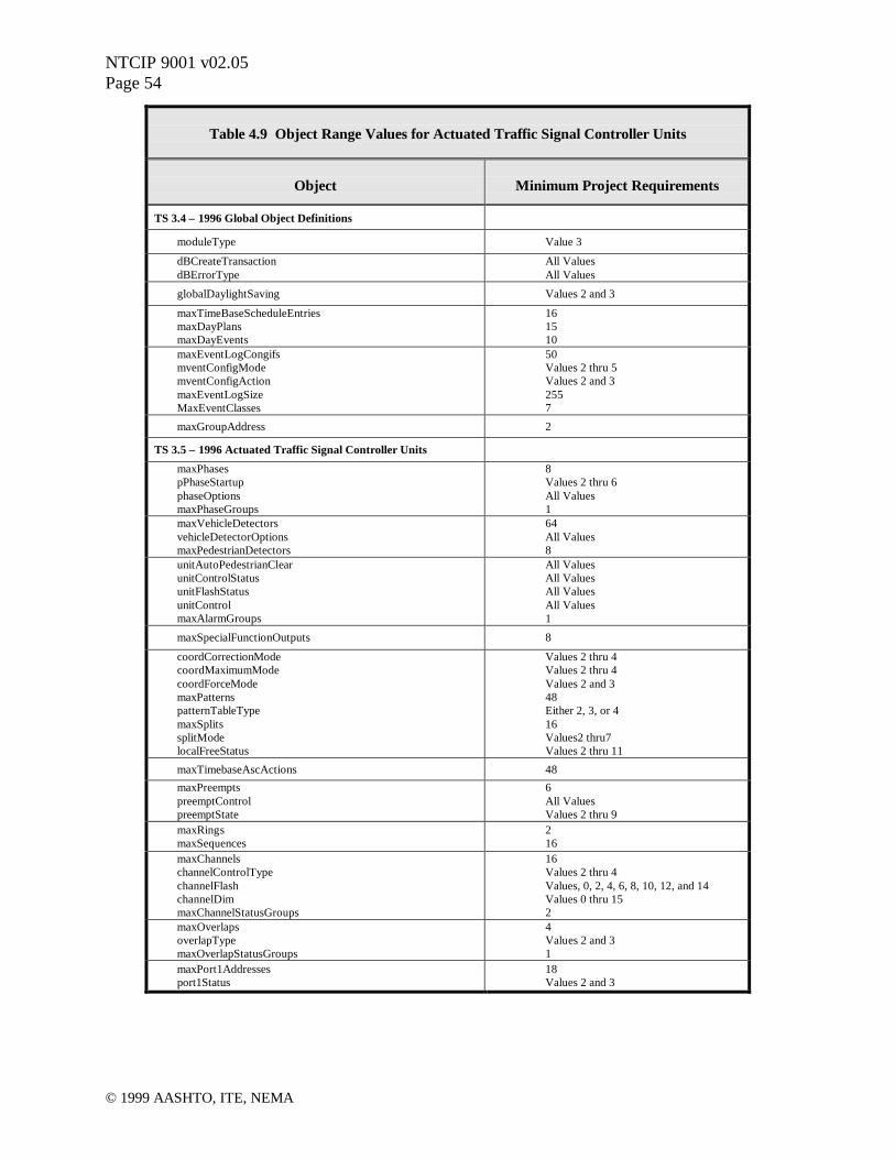
NTCIP 9001 v02.05Page 54
© 1999 AASHTO, ITE, NEMA
Table 4.9 Object Range Values for Actuated Traffic Signal Controller Units
Object Minimum Project Requirements
TS 3.4 – 1996 Global Object Definitions
moduleType Value 3
dBCreateTransactiondBErrorType
All ValuesAll Values
globalDaylightSaving Values 2 and 3
maxTimeBaseScheduleEntriesmaxDayPlansmaxDayEvents
161510
maxEventLogCongifsmventConfigModemventConfigActionmaxEventLogSizeMaxEventClasses
50Values 2 thru 5Values 2 and 32557
maxGroupAddress 2
TS 3.5 – 1996 Actuated Traffic Signal Controller Units
maxPhasespPhaseStartupphaseOptionsmaxPhaseGroups
8Values 2 thru 6All Values1
maxVehicleDetectorsvehicleDetectorOptionsmaxPedestrianDetectors
64All Values8
unitAutoPedestrianClearunitControlStatusunitFlashStatusunitControlmaxAlarmGroups
All ValuesAll ValuesAll ValuesAll Values1
maxSpecialFunctionOutputs 8
coordCorrectionModecoordMaximumModecoordForceModemaxPatternspatternTableTypemaxSplitssplitModelocalFreeStatus
Values 2 thru 4Values 2 thru 4Values 2 and 348Either 2, 3, or 416Values2 thru7Values 2 thru 11
maxTimebaseAscActions 48maxPreemptspreemptControlpreemptState
6All ValuesValues 2 thru 9
maxRingsmaxSequences
216
maxChannelschannelControlTypechannelFlashchannelDimmaxChannelStatusGroups
16Values 2 thru 4Values, 0, 2, 4, 6, 8, 10, 12, and 14Values 0 thru 152
maxOverlapsoverlapTypemaxOverlapStatusGroups
4Values 2 and 31
maxPort1Addressesport1Status
18Values 2 and 3

NTCIP 9001 v02.05Page 55
© 1999 AASHTO, ITE, NEMA
4.4 Center-to-Center
NTCIP defines two application level protocols for communications between computers – DataExchange in ASN.1 (DATEX-ASN, commonly referred to as simply DATEX), and CommonObject Request Broker Architecture (CORBA). Both protocols provide the same basicfunctionality, but they differ in the method of implementation and each has some unique features(see Chapter 3). A particular system may support either or both of these protocols. Gateways ortranslators can pass messages between the two when necessary. The Internet Protocol (IP) andboth UDP and TCP are used at the transport level.
Regardless of the application level protocol, center-to-center communications requiresparticipating systems to exchange standard messages or objects at the information level. Variouscenter-to-center message sets and object models have been developed or are in development byITS standards development organizations. Most of these are outside of the direct purview ofNTCIP, but their development has been coordinated with the NTCIP center-to-center applicationprotocol working group. The following standard inter-systems message sets have been defined,or are being defined, and can be used with DATEX:
• Traffic Management Center External Messages• Transit Communications Interface Profiles• Incident Management Messages• Traveler Information Messages• DATEX-ASN Administrative Messages
Various object models are in development for use with CORBA, but no standard models haveyet been published.
The choice of protocol and message sets/object model depends on the application andenvironment. The following factors are relevant:
Note: The reader is reminded that center-to-center communications take place betweencomputer systems, and those computers or systems may be within the same “center” or inseparate centers. The following questions really apply to each system, including multiplesystems within one center where relevant.
• Is the procurement for just one center, or multiple centers?• Is there an immediate need for center-to-center communications, or is the procurement
for future use?• Do other centers with which this one is likely to interact already have a DATEX or
CORBA interface?• What types of information will this center likely need to send or receive (traffic signal,
freeway, other traffic management, transit, emergency, traveler information)?• Is the procurement part of a new or upgraded system implementation, or an add-on to an
existing system?• Does the center use object oriented software?

NTCIP 9001 v02.05Page 56
© 1999 AASHTO, ITE, NEMA
• Can one or more connected centers now or in the near future provide gateway/translationservices between DATEX and CORBA?
If multiple centers are to have center-to-center support added as part of the procurement, or inthe near future, these questions need to be considered for each such center. It is desirable foragencies within a region to jointly consider these issues and make coordinated procurementswhere feasible to minimize costs and facilitate rapid achievement of all needed center-to-centerlinks in the region.
Ultimately, it is hoped that all centers and systems for transportation management will have aDATEX and/or CORBA interface, just as virtually all computers now have standard protocolsupport for commonly used Internet communications, such as e-mail, web access, and filetransfer. Systems with center-to-center protocol support will be able to automatically exchangetransportation data with any other system with the same protocol, using the Internet or a privateInternet Protocol based communications network.
The NTCIP center-to-center protocols and related message sets and object models are necessary,but not sufficient for two centers to usefully exchange data. Application software is needed togather, process, display, interpret, act on, and generate the incoming or outgoing data. The sameis true of any protocol. For example, the Internet’s Simple Mail Transfer Protocol is a standardfor e-mail transfer between computers, but a computer needs more than the protocol, it alsoneeds an e-mail program that enables a user to compose and send mail, retrieve and read mail, toarchive both sent and received messages, etc.
Center-to-center communications between computer systems will work only if the computershave suitable application software. This software does not have to be standardized, just asMicrosoft’s Outlook e-mail program works quite differently from Netscape’s Communicatorprogram, but e-mail can be sent between the two because they both use the Simple Mail TransferProtocol.
Some of the functions that a center may need in a center-to-center communications managementsoftware package include the following:
• User interface (e.g., subscription form, data display, status reports, etc.)• Interpretation and appropriate disposition of incoming messages• Databases for storing subscriptions and other administrative data• Interfaces with existing transportation databases and programs• Network performance monitoring and management• Event logging and reporting, etc.
None of these functions are specified or provided by the center-to-center protocols or messagesets, since they do not have to be standardized. But at least some will need to be provided for asystem to manage and make use of center-to-center communications. A system may choose toobtain a very elaborate and sophisticated center-to-center communications management package,or a basic one. The former will provide more functions and be easier to use, but will cost more.

NTCIP 9001 v02.05Page 57
© 1999 AASHTO, ITE, NEMA
Center-to-center protocol software and center-to-center communications management softwareare most easily provided as part of the initial development or implementation of a system, orduring a system upgrade. However, it is possible to add on center-to-center software at any time.
Adding center-to-center software to an existing system can be achieved in either of two basicways:
• Keep the center-to-center protocol and management software separate from the existingtransportation management software – usually on a separate computer and with a separateuser interface. This involves a loosely coupled connection between the two softwarepackages, which may make use of an existing data interface available in thetransportation management system, thus avoiding or minimizing the need for changes tothe existing software.
• Tightly couple the center-to-center protocol and management software with the existingtransportation management software – usually on the same computer, and usually with anintegrated user interface. This involves alteration of the existing software to provide theintegration. This option provides a more integrated application for ease of use and addedfunctionality, but costs more.
The loosely coupled option allows use of a generic center-to-center “server” software packagethat can be replicated at multiple centers, with different interfaces to each local system. Thismay minimize costs, but it will likely mean users have to deal with two separate user interfaces,incoming data may not be viewable on the same dynamic displays as local data, data from othercenters may not be able to be easily combined with local data in analysis and reports, and someremote control functions may not be supported. The tightly coupled approach and its functionalbenefits can often be obtained much more economically if it is provided as part of a new systemdevelopment or upgrade and is part of the overall system requirements and specifications.
Eventually, each center will ideally support both the CORBA and DATEX protocols and allstandard message sets and object models. If it is not practical to add support for both protocols, acenter should provide, if feasible, the one that other centers in the area are already using or haveplanned, if any, and otherwise choose the one most suited to its abilities and needs. For example,object oriented systems will probably implement CORBA because it will be easier and morecapable. Non-object oriented systems will probably implement DATEX because CORBA willbe awkward for them. It is anticipated that state, regional, and large transportation managementcenters will support both protocols and also provide a regional translation or bridging service toenable data exchange between local systems with single but different protocols.
Finally, for center-to-center communications to operate, a computer network connection isneeded between the centers. Any local or wide area network that supports the Internet Protocolis adequate. The Internet can be used, but many centers are reluctant to do this until bettersecurity measures are available. Latency is also an issue when considering use of the Internet.Private wide area network services are readily available from telecommunications companies,including virtual private networks that use the Internet infrastructure. As explained in Chapter 5,there are bandwidth considerations if low speed WAN links (e.g. 56 kbps) are being considered.

NTCIP 9001 v02.05Page 58
© 1999 AASHTO, ITE, NEMA
Dial-up access may be appropriate for remote or occasional data exchanges. Other than theseintroductory comments, the design and specification of the network connection is beyond thescope of this document.

NTCIP 9001 v02.05Page 59
© 1999 AASHTO, ITE, NEMA
5 DESIGNING NTCIP
5.1 Introduction
This chapter is intended to provide an overview of communication bandwidth calculations andsome of the issues that should be considered when designing an NTCIP communications system.While the tile of this section is Designing NTCIP, the focus of the material presented hereindeals with how to design a communications system for use with NTCIP. This section is intendedfor those system designers, system integrators, and manufacturers who are tasked withdetermining communication system design and performance criteria.
This chapter contains the following sections:
• Calculate Bandwidth Requirements- Center-to-Center Bandwidth Requirements- Center-to-Field Bandwidth Requirements- Center-to-Field Bandwidth Analysis
- Estimate Message Exchanges and Frequency- Estimate Application Message Size
- SNMP Application Message Bits and Bytes- STMP Application Message Bits and Bytes
- Estimate Application Message Exchanges- SNMP Application Message Exchange Sizes- STMP Application Message Exchange Sizes
- Estimate Transport and Subnetwork Protocol Size- Estimate Timing Factors- Modems
- Electrical Limitations- Communications Limitations
- SNMP Timing- STMP Timing
- Center-to-Field Bandwidth Alternate Analysis- Estimate Message Exchanges and Frequency
- SNMP Application Message Exchange Sizes- STMP Application Message Exchange Sizes
- Other Estimates- Number and Size of Slots per Channel- Communications Drops (Drops per Channel)- SNMP Timing- STMP Timing
5.2 Calculate Bandwidth Requirements
The NTCIP Standards do not address issues related to specifying bandwidth requirements or howbandwidth is allocated. Bandwidth is basically how much information can be sent through a

NTCIP 9001 v02.05Page 60
© 1999 AASHTO, ITE, NEMA
connection. It is usually expressed as bits-per-second. Most communications networks permitmultiple applications, users and / or devices to access a common communications link. Sharingthe link must be equitable. Some NTCIP Standards address the requirements of severalcommunications links or subnetworks, but do not state which ones will be used for specificapplications. These are application and implementation specific issues. Planners andimplementers must decide these issues. This leads to the question of whether a communicationslink or subnetwork has enough bandwidth to support the desired information exchanges.
An implementation of a system must include specific choice of a subnetwork or subnetworks.That choice must be able to accommodate the information exchanges that are needed for propersetup, operation, and monitoring of a system. Planners and implementers must understand that aspecific media may limit what can be sent. This section provides several examples of how toestimate what can be sent, the overhead associated with sending it, and the organization of thephysical media to support the information exchanges.
5.2.1 Center-to-Center Bandwidth Requirements
Center-to-center communications typically involve communications networks connecting manycomputers in a peer-to-peer arrangement. These networks typically involve both local areanetworks (e.g., within a building or adjacent buildings) and wide area networks (e.g., across townor across the nation). The bandwidth requirements will vary for each link in each network,depending on the amount of center-to-center messaging traffic using that link, and whether or notthe network is shared with other applications. Multiplexers, routers, switches, hubs, and otherdevices are commonly used to manage, segment, and optimize computer networks.
The typical subnetwork consists of a local area network adapter that operates at 10 Mbits-per-second (Mbps). In an office environment, even 100 Mbps is readily available. Point-to-pointdialup and dedicated external links run at a minimum of 56 Kbits-per-second (Kbps). Mostimportantly to a planner or implementer is that there are plenty of information resourcesavailable. Network and communications consultants abound. In today's business environment,there is usually a computer guru or network administrator that can help understand and quantifybandwidth and allocations issues.
In a center-to-center environment, the computers that run the transportation applications aretypically just users of the "network" or communication links. Other applications such as e-mail,database management, graphics design, and word processing may also users of the network.This has a big advantage when it comes to design and implementation. A network specialistusually handles its design and implementation. However, they expect the transportation systemdesigner or implementer to be able to quantify what demands will be placed on the network.
The NTCIP center-to-center protocols (DATEX and CORBA) are used for two basic types ofmessage exchange. The first type involves a human operator at a center requesting informationon a one-time basis from another center. Since a human is in the loop, the volume of suchmessages is small, and they are unlikely to be critical in any network design. The other type ofmessaging occurs when an operator at a center sets up a permanent subscription for data to be

NTCIP 9001 v02.05Page 61
© 1999 AASHTO, ITE, NEMA
sent from another center automatically – no human in the loop – and repeatedly. Suchsubscriptions may request the data to be sent every x seconds, or only when it changes. In mostcases, network traffic is minimized if subscriptions specify change-based triggers rather thantime based. Since each center can establish any number of permanent subscriptions with each ofany number of other centers on the network, this is the type of messaging that can potentiallyoverload the network, or at least some links in the network.
It may be difficult for a system designer to anticipate all the different types of data that may besubscribed for between each pair of centers. It is recommended that designers gather actualoperating experience from exiting center-to-center networks to help make such estimates. Oneimportant consideration is the frequency of change in status or other data at each center, sincechanges are what other centers will be interested in monitoring. For example, a center thatmanages only incidents and related information is not likely to generate as much message trafficon the network as one that manages 200 traffic signals each of which changes status every fewseconds.
It is possible to perform a worst case analysis by considering the frequency, or quantity persecond, of useful information generation at each center, estimate which other centers will havean interest in receiving that information, and assign the message loads to network linksaccordingly. Some messages will not require a confirmation or other response message, butmany will. These need to be allowed for as well. CORBA also uses various administrative andexchange initiation messages that can add more traffic on the channel. Further allowance needsto be made for retries when a message is not delivered successfully on the first attempt.
For DATEX, each IP packet containing data (a publication message – the most common type)will contain at least 70 bytes of overhead information (including the IP header), plus the actualencoded data. Most messages will contain only a relatively small quantity of actual data – say 20to 100 bytes. An average DATEX-generated IP packet might contain 150 bytes. At this rate, afull duplex 56 Kbps wide area network link could support in the order of 30 messages per secondin each direction. This will be sufficient for some centers, such as the incident managementcenter, but may not be sufficient for others such as the large traffic signal system, or a center thatwants to obtain a lot of data from other centers.
Figure 5.1 illustrates all the typical fields and values used in sending a set globalTime messageover a typical office environment, network communications stack. The message is sent via theSNMP Application Profile over a UDP/IP Transport Profile over an Ethernet SubnetworkProfile. Figure 5.2 illustrates the same globalTime message sent via the STMP ApplicationProfile over the same transport and subnetwork.
5.2.2 Center-to-Field Bandwidth Requirements
In center-to-field communications, bandwidth considerations are of great concern to planners andimplementers. Unlike an office environment, center-to-field communications links are generallyless than 56 Kbps. Hundreds of existing systems use multi-drop, 1200 bps modems.Compounding the issue, these links tend to be dedicated to the transportation application and are

NTCIP 9001 v02.05Page 62
© 1999 AASHTO, ITE, NEMA
the full responsibility of the transportation personnel to design, implement, and maintain. Thefollowing bandwidth analyses should help to understand the factors and thinking that go intounderstanding bandwidth requirements and calculating an appropriate communications data rate.However, it should be noted that many other devices, such as dynamic message signs, advisoryradio transmitters, ramp meters, traffic detector stations, and weather stations are usually muchless sensitive to timing and latency issues, and can typically operate satisfactorily with SNMP,even at 1200 bps.
The two analyses will be used to discuss a few of the many alternative techniques that can beused in a center-to-field multi-drop communications system using NTCIP. Examples (by nomeans a complete list) of options available include:
• Use SNMP for all or some messages• Use STMP for all or some messages• Use only standard objects, or also use some manufacturer specific objects• Use a bit rate of 1200, 2400, 4800, 9600, 19200, or other• Use half duplex or full duplex communications• For full duplex, overlap or don’t overlap outgoing with incoming messages• Use twisted pair, fiber, radio, leased lines, or other media• For twisted pair and leased lines, use one or two pairs per channel• Use modems that are fast or slow to reach ready state when needed• Limit the maximum number of devices on a channel to 2, 4, 6, 8, 10, or other number• Gather detector data on a clock time basis (e.g. every minute) or signal cycle basis• Request each type of data every second, every minute, or every hour, etc.• Use a fixed or variable polling cycle duration• Use a fixed or variable device sequence in the polling cycle• Use a fixed or variable message sequence for each device• Wait for response in same poll or get it in next poll• Interleave upload /download messages or suspend status and “get it over with ASAP”• Use the same status message all the time, or different status messages• Insert occasional non-status requests in place of or in addition to status request• Allow spare time in a polling cycle for additional non-status messages, or allow the cycle
to expand when non-status messages added
With the exception of manufacturer-specific data objects, any controller that meets allmandatory, optional, and recommended requirements of the relevant NTCIP center-to-fieldstandards for that field device type, will support all of the relevant functions and operationssuggested above and many more, without any software change.
5.2.3 Center-to-Field Bandwidth Analysis
For purposes of discussion, lets say it is desired to use NTCIP center-to-field communications inan imaginary traffic control system. The system consists of a central management applicationthat is used to setup, monitor, and control a network of intersection traffic signal controllers. Theprimary communications requirements of the imaginary system are:
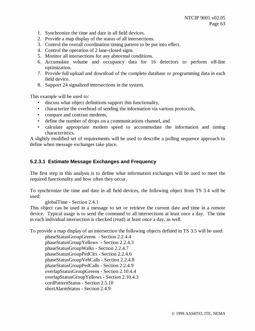
NTCIP 9001 v02.05Page 63
© 1999 AASHTO, ITE, NEMA
1. Synchronize the time and date in all field devices.2. Provide a map display of the status of all intersections.3. Control the overall coordination timing pattern to be put into effect.4. Control the operation of 2 lane-closed signs.5. Monitor all intersections for any abnormal conditions.6. Accumulate volume and occupancy data for 16 detectors to perform off-line
optimization.7. Provide full upload and download of the complete database or programming data in each
field device.8. Support 24 signalized intersections in the system.
This example will be used to:• discuss what object definitions support this functionality,• characterize the overhead of sending the information via various protocols,• compare and contrast modems,• define the number of drops on a communications channel, and• calculate appropriate modem speed to accommodate the information and timing
characteristics.A slightly modified set of requirements will be used to describe a polling sequence approach todefine when message exchanges take place.
5.2.3.1 Estimate Message Exchanges and Frequency
The first step in this analysis is to define what information exchanges will be used to meet therequired functionality and how often they occur.
To synchronize the time and date in all field devices, the following object from TS 3.4 will beused:
globalTime - Section 2.4.1This object can be used in a message to set or retrieve the current date and time in a remotedevice. Typical usage is to send the command to all intersections at least once a day. The timein each individual intersection is checked (read) at least once a day, as well.
To provide a map display of an intersection the following objects defined in TS 3.5 will be used:phaseStatusGroupGreens - Section 2.2.4.4phaseStatusGroupYellows - Section 2.2.4.3phaseStatusGroupWalks - Section 2.2.4.7phaseStatusGroupPedClrs - Section 2.2.4.6phaseStatusGroupVehCalls - Section 2.2.4.8phaseStatusGroupPedCalls - Section 2.2.4.9overlapStatusGroupGreens - Section 2.10.4.4overlapStatusGroupYellows - Section 2.10.4.3cordPatternStatus - Section 2.5.10shortAlarmStatus - Section 2.4.9

NTCIP 9001 v02.05Page 64
© 1999 AASHTO, ITE, NEMA
These objects provide green and yellow indications for up to 8 vehicle phases and 8 overlaps,walk and pedestrian clearance indications for up to 8 pedestrian movements, the currentcoordination pattern (cycle, split, and offset) in effect, and an indication of preemption, problemswith the coordination pattern, any detector fault, or some other type of fault condition. Thisinformation is intended to provide a real-time display and is typically read from each intersectioncontroller on a once-per-second basis.
To control the timing pattern to put into effect and turn on and off the lane closed signs, thefollowing objects from TS 3.5 will be used:
systemPatternControl - Section 2.5.14specialFunctionOutputState (1) - Section 2.4.14.2specialFunctionOutputState (2) - Section 2.4.14.2
This information is intended to be sent to all intersections about once per minute.
To retrieve volume and occupancy data from 2 volume / occupancy detectors at a time, thefollowing objects from TS 3.5 will be used:
volumeOccupencySequence - Section 2.3.5.1detectorVolume (1) - Section 2.3.5.4detectorOccupency (1) - Section 2.3.5.4detectorVolume (2) - Section 2.3.5.4detectorOccupency (2) - Section 2.3.5.4
The volume and occupancy data would be read approximately once-per-minute. It is typical tohave "count stations" spread out over several intersections. This type of information would beasked for from the intersections that have one or more count stations.
To provide additional information about the status of an intersection, the following objects willbe used:
unitAlarmStatus1 - Section 2.4.8localFreeStatus - Section 2.5.11
These objects are to read only when the shortAlarmStatus indicates some type of fault condition.They provide more detail about any potential fault condition. Typically this would occur nomore than once-per-hour.
To provide complete upload and download of a controller's database, the followingimplementation specific, block objects are defined and used for upload and download purposes:
Timing Plan 1 Programming Data (entries for phases 1-16)Timing Plan 2 Programming Data (entries for phases 1-16)Timing Plan 3 Programming Data (entries for phases 1-16)Timing Plan 4 Programming Data (entries for phases 1-16)Vehicle Detector Programming Data (entries for detectors 1-32)Pedestrian Detector Programming Data (entries for detectors 1-16)Vehicle Overlap Programming DataPedestrian Overlap Programming DataTimebase Programming DataCoordination Pattern Programming DataCoordination Permissive Programming Data

NTCIP 9001 v02.05Page 65
© 1999 AASHTO, ITE, NEMA
Conditional Service and Dual Entry DataEvent Programming DataPreempt Programming DataUnit Configuration Programming DataCommunications Programming Data
These block objects are defined as implementation or vendor specific OCTET STRING [anASN.1 data type that is used to specify octets (eight-bit bytes) of binary or textual information]objects consisting of anywhere between 10 and 128 discrete objects. The individual objects maybe defined in the TS 3.5 Standard or may be implementation or vendor defined objects. Theblock objects could define the entire "database" of a device. They would only be sent andretrieved on an as-needed basis and would, at most, occur no more than once-per-day. Theycould represent the records in file upload or download. While these objects are not currentlydefined in an NTCIP standard, they represent real system requirements.
In the course of fine tuning an intersection, numerous programming entries for phase timing andcoordination might be sent once or twice a day. The following objects would be typical:
phaseWalk - Section 2.2.2.2phaseMinumumGreen - Section 2.2.2.4phasePassage - Section 2.2.2.5patternCycleTime - Section 2.5.7.2patternOffsetTime - Section 2.5.7.3splitTime - Section 2.5.9.2
The typical intersection is set up for 5-phase operation and has only 6 timing patterns defined. Itis assumed that only one phase or pattern would be adjusted at any one time. Therefore, thenumber of objects associated with this type of operation is assumed to be 5.
The following table summarizes the messages and the how often they occur.
Table 5.1 Frequency of Messages
Message Exchange Frequency
Date and Time 1 per day - all
Intersection Map Data 1 per secondX 24 intersections
Pattern Command 1 per minute - all
Detector Data 1 per minuteX 8 intersections
Detailed Status 1 per hourX 8 intersections
Upload Download 1 per dayX 24 intersections
Tuning 2 per dayX 24 intersections
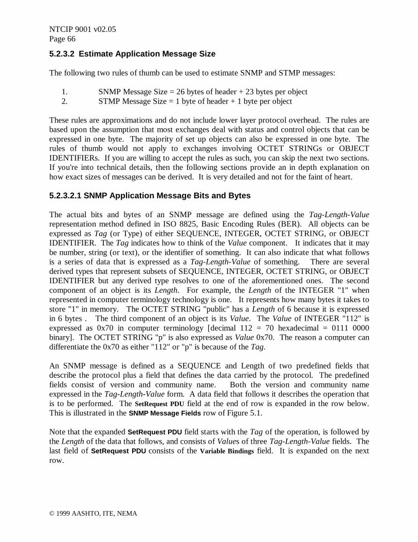
NTCIP 9001 v02.05Page 66
© 1999 AASHTO, ITE, NEMA
5.2.3.2 Estimate Application Message Size
The following two rules of thumb can be used to estimate SNMP and STMP messages:
1. SNMP Message Size = 26 bytes of header + 23 bytes per object2. STMP Message Size = 1 byte of header + 1 byte per object
These rules are approximations and do not include lower layer protocol overhead. The rules arebased upon the assumption that most exchanges deal with status and control objects that can beexpressed in one byte. The majority of set up objects can also be expressed in one byte. Therules of thumb would not apply to exchanges involving OCTET STRINGs or OBJECTIDENTIFIERs. If you are willing to accept the rules as such, you can skip the next two sections.If you're into technical details, then the following sections provide an in depth explanation onhow exact sizes of messages can be derived. It is very detailed and not for the faint of heart.
5.2.3.2.1 SNMP Application Message Bits and Bytes
The actual bits and bytes of an SNMP message are defined using the Tag-Length-Valuerepresentation method defined in ISO 8825, Basic Encoding Rules (BER). All objects can beexpressed as Tag (or Type) of either SEQUENCE, INTEGER, OCTET STRING, or OBJECTIDENTIFIER. The Tag indicates how to think of the Value component. It indicates that it maybe number, string (or text), or the identifier of something. It can also indicate that what followsis a series of data that is expressed as a Tag-Length-Value of something. There are severalderived types that represent subsets of SEQUENCE, INTEGER, OCTET STRING, or OBJECTIDENTIFIER but any derived type resolves to one of the aforementioned ones. The secondcomponent of an object is its Length. For example, the Length of the INTEGER "1" whenrepresented in computer terminology technology is one. It represents how many bytes it takes tostore "1" in memory. The OCTET STRING "public" has a Length of 6 because it is expressedin 6 bytes . The third component of an object is its Value. The Value of INTEGER "112" isexpressed as 0x70 in computer terminology [decimal 112 = 70 hexadecimal = 0111 0000binary]. The OCTET STRING "p" is also expressed as Value 0x70. The reason a computer candifferentiate the 0x70 as either "112" or "p" is because of the Tag.
An SNMP message is defined as a SEQUENCE and Length of two predefined fields thatdescribe the protocol plus a field that defines the data carried by the protocol. The predefinedfields consist of version and community name. Both the version and community nameexpressed in the Tag-Length-Value form. A data field that follows it describes the operation thatis to be performed. The SetRequest PDU field at the end of row is expanded in the row below.This is illustrated in the SNMP Message Fields row of Figure 5.1.
Note that the expanded SetRequest PDU field starts with the Tag of the operation, is followed bythe Length of the data that follows, and consists of Values of three Tag-Length-Value fields. Thelast field of SetRequest PDU consists of the Variable Bindings field. It is expanded on the nextrow.

NTCIP 9001 v02.05Page 67
© 1999 AASHTO, ITE, NEMA
As before, it begins as a Tag-Length-Value of a SEQUENCE and Length of one or moreBindings. The last row in the figure is getting closer to defining the actual data is, but we have togo through another Tag-Length-Value sequence to describe the identity and value of a singleobject or Bindings.
From the communications perspective, each of the objects defined in one of the ObjectDefinitions Standards such as TS 3.4 or TS 3.5 has two components: an identity and a value.The identity part of the globalTime object is its OBJECT IDENTIFIER (OID). The full OID ofglobalTime is:<iso.org.dod.internet.private.enterprises.nema.transportation.devices.global.globalTimeManagement.1>
or<1.3.6.1.4.1.1206.4.2.6.3.1.0>
The value component of globalTime is an INTEGER with a value such as 925997608. Thisparticular value represents May 6, 1999 at 2:33 PM UCT expressed as the seconds sinceMidnight January 1, 1970. For a more detailed discussion on OID, please refer to Section 6.
The actual number of bytes that are used to encode the identity and value of the globalTimeobject varies with protocols used. For SNMP, each component of the object is expressed in theform of (you guessed it) Tag-Length-Value. For globalTime, the identity Tag is OID (0x06).The identify Length value is 13 (0x0D). The identity Value is 1.3.6.1.4.1.1206.4.2.6.3.1.0(0x2B060104018936040206030100). For the value component, the value Tag is INTEGER(0x02). The value Length is 4 (0x04). The value Value is 925997608 (0x37319A28).
If one goes through this exercise with various objects, one can derive some generalcharacteristics about the objects used in this analysis. Most objects are organized into tables andthe OIDs of these objects are 15 to 16 bytes long. Unlike globalTime, most objects are definedas INTEGERs that, in the traffic signal controller application, have a value between 0 and255. Most values are therefore expressed in one or two bytes. Compared to the example ofglobalTime, a typical identity would 2-3 bytes longer and the value would be 2-3 bytes shorter.The average binding for an individual object is therefore 23 bytes, as shown in Figure 5.1. Thefixed overhead of SNMP messages that are used to get or set one or more objects is 26 bytes, asshown in Figure 5.1.

NTCIP 9001 v02.05Page 68
© 1999 AASHTO, ITE, NEMA
5.2.3.2.2 STMP Application Message Bits and Bytes
The actual bits and bytes of an STMP message are defined using Octet Encoding Rules (OER),as described in NTCIP 1102 – NTCIP Octet Encoding Rules (OER). Because the content of anSTMP message is defined prior to being sent, it is possible to eliminate a number of fields andreduce overhead significantly. OER starts out with the Tag-Length-Value representation methodused by SNMP. However, if the Tag, Length, or Value is known, the component is eliminated.If an object is always an INTERGER, the fact that it is an INTEGER is not sent. If an object isalways 2 bytes long, the fact that it is 2 bytes long is not sent. Since all data are expressed as a
Figure 5.1 Set Time operation using SNMP over PMPP
PMPP Frame FieldsFlag Address Control Information FCS Flag
7E FF CO xx xx 7Ebroadcastaddress
UI FramePoll = 0
CRC
Information FieldIPI SNMP MessageC1
IPI =SNMP/STMP
SNMP Message FieldsSequence Length Version Community Name SetRequest PDU
30 2F 02 01 00 04 06 70 75 62 6c 69 63
Seq Tag Length ofwhat follows= 47 Bytes
Integer TagLength ValueVersion = 0
Octet Length NameString = 6 = "public" Tag
SetRequest PDUPDUType
PDULength
Request ID Error Status Error Index Variable Bindings
A3 22 02 01 00 02 01 00 02 01 00PDU Tag Length of
whatfollows
= 34
Integer TagLength Value
ID = 0
Integer TagLength Value
Status = 0
Integer TagLength Value
Index = 0
Variable BindingsSequence of Length Bindings
30 17Seq Tag Length of all Bindings
BindingSequence Length Identity Value
30 15 06 0D 2B 06 01 04 01 89 36 04 02 06 03 01 00 02 04 37 31 9A 28Seq Tag Length of identity
- value pair = 21OID Length Identity = 1.3.6.1.4.1.1206.4.2.6.3.1.0Tag = 13 globalTime
Integer Length Value = tag = 4 925997608

NTCIP 9001 v02.05Page 69
© 1999 AASHTO, ITE, NEMA
SEQUENCE, all SEQUENCE Tags and SEQUENCE Lengths are eliminated as well. What thisall boils down to is that only the Value of an object is sent.
In Figure 5.1, the Binding for globalTime consisted of Sequence, Length, and Value of theIdentity and Value pair where the Identity and Value pair were each encoded as Tag-Length-Value. The Binding in STMP would be the Value-Value or simply 0x37319A28 as shown in thelast row of Figure 5.3. It is worth noting here that the same principle of eliminating any knownTag, Length, or Value was applied to the SNMP Message Fields, Set Request PDU, and VariableBindings fields in Figure 5.1. This resulted in the one-byte STMP Message Fields and SetRequest PDU field shown in Figure 5.2
5.2.3.3 Estimate Application Message Exchanges
In any exchange of messages, one has to consider the size of both the command and response. InSNMP, the size of the command and response are approximately the same size. In STMP, thesize of the command and response are very different. The following two sections discuss thedetails.
Figure 5.2 Set Time operation using STMP over PMPP
PMPP Frame FieldsFlag Address Control Information FCS Flag
7E FF CO xx xx 7Ebroadcastaddress
UI FramePoll = 0
CRC
Information FieldInitial
Protocol IDSTMP Message
C1IPI = SNMP/
STMP
STMP Message Fieldsand Set Request PDU
PDU Header Predefined Binding 1101 0001 (Bits) SetRequest Dynamic Msg 1 - NoReply (Time)
BindingValue
37 31 9A 28Time Value =925997608
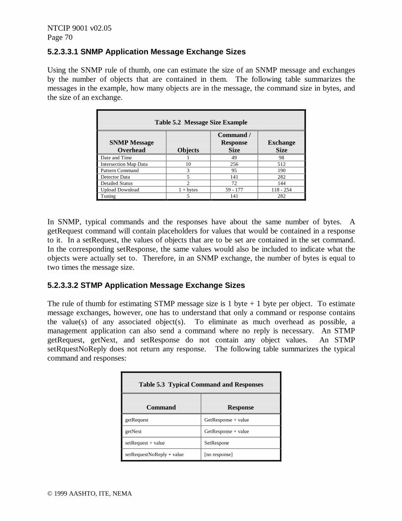
NTCIP 9001 v02.05Page 70
© 1999 AASHTO, ITE, NEMA
5.2.3.3.1 SNMP Application Message Exchange Sizes
Using the SNMP rule of thumb, one can estimate the size of an SNMP message and exchangesby the number of objects that are contained in them. The following table summarizes themessages in the example, how many objects are in the message, the command size in bytes, andthe size of an exchange.
Table 5.2 Message Size Example
SNMP MessageOverhead Objects
Command /Response
SizeExchange
SizeDate and Time 1 49 98Intersection Map Data 10 256 512Pattern Command 3 95 190Detector Data 5 141 282Detailed Status 2 72 144Upload Download 1 + bytes 59 - 177 118 - 254Tuning 5 141 282
In SNMP, typical commands and the responses have about the same number of bytes. AgetRequest command will contain placeholders for values that would be contained in a responseto it. In a setRequest, the values of objects that are to be set are contained in the set command.In the corresponding setResponse, the same values would also be included to indicate what theobjects were actually set to. Therefore, in an SNMP exchange, the number of bytes is equal totwo times the message size.
5.2.3.3.2 STMP Application Message Exchange Sizes
The rule of thumb for estimating STMP message size is 1 byte + 1 byte per object. To estimatemessage exchanges, however, one has to understand that only a command or response containsthe value(s) of any associated object(s). To eliminate as much overhead as possible, amanagement application can also send a command where no reply is necessary. An STMPgetRequest, getNext, and setResponse do not contain any object values. An STMPsetRquestNoReply does not return any response. The following table summarizes the typicalcommand and responses:
Table 5.3 Typical Command and Responses
Command Response
getRequest GetResponse + value
getNext GetResponse + value
setRequest + value SetRespone
setRequestNoReply + value [no response]

NTCIP 9001 v02.05Page 71
© 1999 AASHTO, ITE, NEMA
The next table shows what commands will be used to set or get the objects. It also lists the sizefor each command and response. By summing the size of the command and response, the size ofthe message exchange can be derived.
Table 5.4 Derivation of STMP Message Exchange Sizes
Size
Dynamic Message Command# of
ObjectsCommand Response Exchange
Date and Time setRequestNoReply 1 2 - 2*
Date and Time getRequest 1 1 2 3*
Intersection Map Data getRequest 10 1 11 12
Pattern Command setRequestNoReply 3 4 - 4
Detector Data getRequest 9 1 10 10
Detailed Status getRequest 2 1 3 3
Upload Download N/A - - - -
Tuning N/A - - - -
* As with any rule of thumb, it does not always apply. The actual sizes are 5 and 6, respectively.
The setting of Date and Time and Pattern Command will be handled with thesetRequestNoReply commands. Retrieving of Date and Time will be handled with a getRequestcommand and getResponse reply. The Intersection Map Data, Detector Data, and DetailedStatus will be handled with the getRequest command and getResponse response. Several UploadDownload messages could, in theory, be defined as Dynamic Objects. However, the limitednumber of definable Dynamic Objects (13) would tend to preclude this. Some implementationsmay specifically prohibit this, as well. The Tuning message while easily defined in SNMPcannot be predefined in STMP because various phases and patterns would have to be indexed.
5.2.3.4 Estimate Transport and Subnetwork Protocol Size
The Point-to-MultiPoint (PMPP) and Point-to-Point Protocols (PPP) share a common headerstructure that has 6 fields associated with it. These fields consist of starting flag, address,control, information, checksum, and a closing flag. The address field in PMPP is typically onebyte but could be extended. The address field in PPP is always 0xFF and is one byte. The fieldsare illustrated in Figure 5.1, in the PMPP Frame Fields row.
The first field in the Information Field indicates the next higher level protocol to process theinformation. This field is referred to as the Initial Protocol Identifier (IPI). For non-networkedcommunications, a "null" or no transport or network protocol is used. The IPI in this case is0xC1 and indicates that the information should be passed directly to SNMP or STMP.
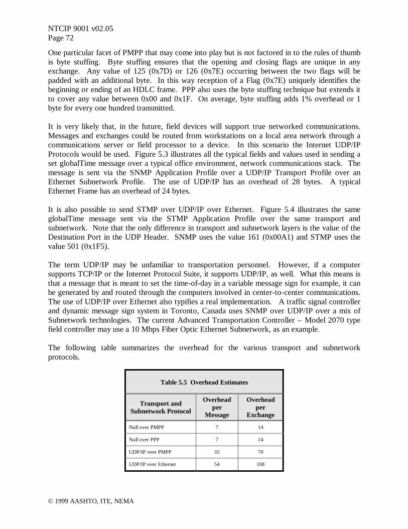
NTCIP 9001 v02.05Page 72
© 1999 AASHTO, ITE, NEMA
One particular facet of PMPP that may come into play but is not factored in to the rules of thumbis byte stuffing. Byte stuffing ensures that the opening and closing flags are unique in anyexchange. Any value of 125 (0x7D) or 126 (0x7E) occurring between the two flags will bepadded with an additional byte. In this way reception of a Flag (0x7E) uniquely identifies thebeginning or ending of an HDLC frame. PPP also uses the byte stuffing technique but extends itto cover any value between 0x00 and 0x1F. On average, byte stuffing adds 1% overhead or 1byte for every one hundred transmitted.
It is very likely that, in the future, field devices will support true networked communications.Messages and exchanges could be routed from workstations on a local area network through acommunications server or field processor to a device. In this scenario the Internet UDP/IPProtocols would be used. Figure 5.3 illustrates all the typical fields and values used in sending aset globalTime message over a typical office environment, network communications stack. Themessage is sent via the SNMP Application Profile over a UDP/IP Transport Profile over anEthernet Subnetwork Profile. The use of UDP/IP has an overhead of 28 bytes. A typicalEthernet Frame has an overhead of 24 bytes.
It is also possible to send STMP over UDP/IP over Ethernet. Figure 5.4 illustrates the sameglobalTime message sent via the STMP Application Profile over the same transport andsubnetwork. Note that the only difference in transport and subnetwork layers is the value of theDestination Port in the UDP Header. SNMP uses the value 161 (0x00A1) and STMP uses thevalue 501 (0x1F5).
The term UDP/IP may be unfamiliar to transportation personnel. However, if a computersupports TCP/IP or the Internet Protocol Suite, it supports UDP/IP, as well. What this means isthat a message that is meant to set the time-of-day in a variable message sign for example, it canbe generated by and routed through the computers involved in center-to-center communications.The use of UDP/IP over Ethernet also typifies a real implementation. A traffic signal controllerand dynamic message sign system in Toronto, Canada uses SNMP over UDP/IP over a mix ofSubnetwork technologies. The current Advanced Transportation Controller – Model 2070 typefield controller may use a 10 Mbps Fiber Optic Ethernet Subnetwork, as an example.
The following table summarizes the overhead for the various transport and subnetworkprotocols.
Table 5.5 Overhead Estimates
Transport andSubnetwork Protocol
Overheadper
Message
Overheadper
Exchange
Null over PMPP 7 14
Null over PPP 7 14
UDP/IP over PMPP 35 70
UDP/IP over Ethernet 54 108

NTCIP 9001 v02.05Page 73
© 1999 AASHTO, ITE, NEMA
Figure 5.3 Set Time operation using SNMP over UDP/IP/Ethernet
Ethernet Frame FieldsPreamble Destination
AddressSourceAddress
Typeor Len
Data FCS IFG
8 Bytes 08 00 90 03 4C F1Bay Net 034CF1
08 00 20 09 00 C83Com 0900C8
08 00IPI = IP
4Bytes
96Bytes
CRCInformation Field
IP Header UDP Header SNMP Message
IP HeaderVer IHL Type of Service Total Length 45 00 00 7C
Identifier Flags Fragment Offset 4E 57 00 00
Time to Live Protocol Header Checksum 3C 11 A5 C5
Source Address 84 A3 80 04
Destination Address 84 A3 01 0A
UDP HeaderSource Port Destination Port 0C A2 00 A1
Length Checksum 00 39 00 00
SNMP Message FieldsSEQUENCE Version Community Name SetRequest PDU30 2F 02 01 00 04 06 70 75 62 6c 69 63
SeqTag
Length = 47(# bytesthat follow)
Int Len Value Tag = 1 = 0
Octet Length NameString = 6 = "public" Tag
SetRequest PDUPDU Type Request ID Error Status Error Index Variable Bindings
A3 22 02 01 00 02 01 00 02 01 00PDUTag
Length = 34(# bytes
that follow)
Int Len Value Tag = 1 = 0
same asRequest ID
same asRequest ID
Variable BindingsSEQUENCE OF VarBinds
30 17SeqTag
Length = 23 (# bytes inall following Bindings)
Variable BindingSEQUENCE Identity Value
30 15 06 0D 2B 06 01 04 01 89 36 04 02 06 03 01 00 02 04 37 31 9A 28SeqTag
Length = 21 (# bytesin this Binding)
OID Length Identity = 1.3.6.1.4.1.1206.4.2.6.3.1.0Tag = 13 globalTime
Integer Length Value = Tag = 4 925997608
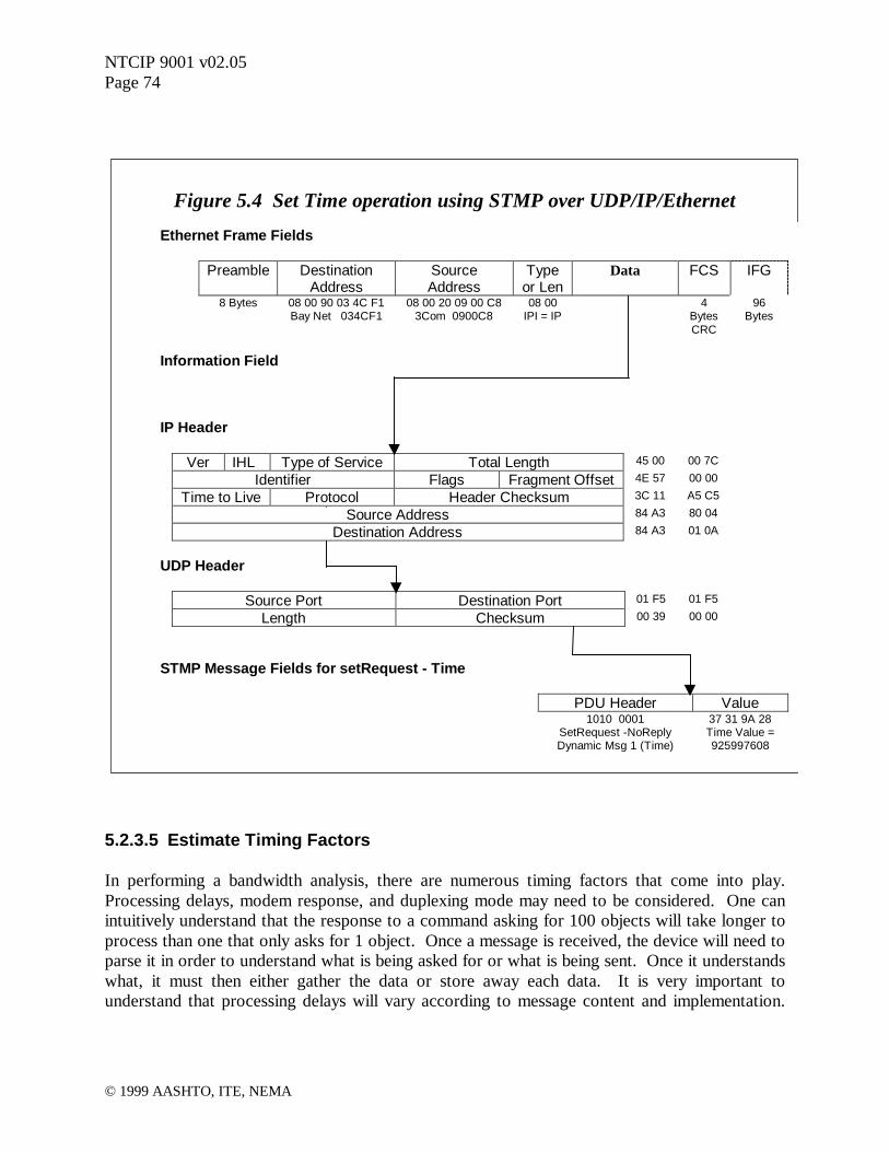
NTCIP 9001 v02.05Page 74
© 1999 AASHTO, ITE, NEMA
5.2.3.5 Estimate Timing Factors
In performing a bandwidth analysis, there are numerous timing factors that come into play.Processing delays, modem response, and duplexing mode may need to be considered. One canintuitively understand that the response to a command asking for 100 objects will take longer toprocess than one that only asks for 1 object. Once a message is received, the device will need toparse it in order to understand what is being asked for or what is being sent. Once it understandswhat, it must then either gather the data or store away each data. It is very important tounderstand that processing delays will vary according to message content and implementation.
Figure 5.4 Set Time operation using STMP over UDP/IP/Ethernet
Ethernet Frame Fields
Preamble DestinationAddress
SourceAddress
Typeor Len
Data FCS IFG
8 Bytes 08 00 90 03 4C F1Bay Net 034CF1
08 00 20 09 00 C83Com 0900C8
08 00IPI = IP
4Bytes
96Bytes
CRC
Information Field
IP Header
Ver IHL Type of Service Total Length 45 00 00 7C
Identifier Flags Fragment Offset 4E 57 00 00
Time to Live Protocol Header Checksum 3C 11 A5 C5
Source Address 84 A3 80 04
Destination Address 84 A3 01 0A
UDP Header
Source Port Destination Port 01 F5 01 F5
Length Checksum 00 39 00 00
STMP Message Fields for setRequest - Time
PDU Header Value1010 0001 37 31 9A 28
SetRequest -NoReplyDynamic Msg 1 (Time)
Time Value =925997608
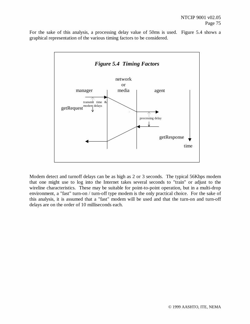
NTCIP 9001 v02.05Page 75
© 1999 AASHTO, ITE, NEMA
For the sake of this analysis, a processing delay value of 50ms is used. Figure 5.4 shows agraphical representation of the various timing factors to be considered.
Modem detect and turnoff delays can be as high as 2 or 3 seconds. The typical 56Kbps modemthat one might use to log into the Internet takes several seconds to "train" or adjust to thewireline characteristics. These may be suitable for point-to-point operation, but in a multi-dropenvironment, a "fast" turn-on / turn-off type modem is the only practical choice. For the sake ofthis analysis, it is assumed that a "fast" modem will be used and that the turn-on and turn-offdelays are on the order of 10 milliseconds each.
Figure 5.4 Timing Factors
time
manager
networkor
media agent
getRequest
getResponse
processing delay
transmit time &modem delays
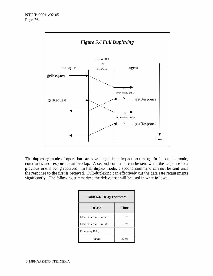
NTCIP 9001 v02.05Page 76
© 1999 AASHTO, ITE, NEMA
The duplexing mode of operation can have a significant impact on timing. In full-duplex mode,commands and responses can overlap. A second command can be sent while the response to aprevious one is being received. In half-duplex mode, a second command can not be sent untilthe response to the first is received. Full-duplexing can effectively cut the data rate requirementssignificantly. The following summarizes the delays that will be used in what follows.
Table 5.6 Delay Estimates
Delays Time
Modem Carrier Turn-on 10 ms
Modem Carrier Turn-off 10 ms
Processing Delay 10 ms
Total 30 ms
Figure 5.6 Full Duplexing
manager
networkor
media agent
getRequest
getResponse
processing delay
time
getRequest
getResponse
processing delay

NTCIP 9001 v02.05Page 77
© 1999 AASHTO, ITE, NEMA
5.2.3.6 Modems
Center-to-field communications have traditionally used 1200 bps FSK (Frequency Shift Keying)modems for wireline communications. These modems come in different versions for differentapplications, such as half or full duplex, leased telephone lines (Bell 3002 voice circuit) oragency-owned twisted pair cable, internal or external to the device, support RS 232 flow controlor not, etc. In analyzing bandwidth requirements for copper communications plant andattempting to increase modem bit rate, it is important to remember that not all modems and bitrates may be practical for a given implementation environment. In particular, the followingissues need to be considered:
• Consumer modems used for general purpose computer communications (e.g., V.9056kbps) cannot be used in multi-drop field implementations because they are too slow toreach ready state prior to each transmission (they require “training” time).
• Consumer modems and modems designed for indoor use may not operate reliably in thetemperature and humidity extremes encountered in field applications.
• The fastest modems currently available for agency-owned twisted pair multi-dropapplications operate at up to 9600 bps.
• Currently, modems suitable for multi-drop operation over leased telephone lines (Bell3002 analog voice circuits) cannot support 9600 bps unless "a metallic circuit" isprovided.
• There is a limit to the distance that a modem can operate on agency-owned twisted paircable. The maximum distance reduces as the bit rate increases and as the number ofdevices on the channel increases.
• There is no distance limit on leased telephone lines.• Modems from different manufacturers can vary greatly in their features and operational
characteristics. A thorough test of the actual modem planned for use (in a real-worldlong distance multi-drop environment) should be made before committing to its use.
• Most field devices do not yet have a 9600 bps internal modem option.• Modems that are external to the field device (connected by a serial cable) require a
dedicated suitable RS 232 port on the field device, in addition to any serial port(s) usedfor other purposes (e.g., laptop computer connection).
• Asynchronous modems add a start and at least one stop bit for every byte (8 bits)transmitted; synchronous modems do not. This equates to 25% additional overhead.
There are similar but different lists of constraints and considerations for modems or transceiversfor other types of plant such as fiber and radio.
5.2.3.6.1 Electrical Limitations
The maximum number of modems on a wireline channel due to electrical limitations is an issueof modem sensitivity, the desired signal-to-noise ratio for a given bit-error-rate, and thecharacteristics of the wire and interface. The Communications Handbook for Traffic Control

NTCIP 9001 v02.05Page 78
© 1999 AASHTO, ITE, NEMA
Systems1 provides an example of the characteristics and calculations for a 1200 bps FSK multi-drop system. The handbook goes into more detail than what is presented here and covers othertechnologies such as wireless and fiber optic.
Following the example in the handbook, the calculations for any modem technology that uses awireline (twisted pair) medium would apply. The formula for determining maximum number ofdrops is:
Number of Drops = (Sensitivity - Cable Loss - S/N Ratio) / Insertion Loss per Drop
The following are hypothetical characteristics of a 9600 bps modem and wiring that is to be usedin a multi-drop configuration.
Table 5.7 Modem Parameters
Parameter Value
Modulation Technique Some type of Phase and Amplitude Modulation
Operation Mode / Line Full Duplex / 4 wire (metallic or user owned)
Modem Frequencies Center Frequency ~ 9600 Hz
Receiver Sensitivity 0 dBM to -39 dBM
Signal-to-Noise Ratio 15 dB for a Bit-Error-Rate of 1 x 10⁻⁵
Cable Loss 3.3 dB/mile at 9600 Hz for 19 AWG
Insertion Loss .5 dB per drop
Distance 8 miles
The modulation technique used by a modem is not necessarily Frequency Shift Keying (FSK).Phase Shift Keying (PSK) and Quadrature Amplitude Modulation (QAM) are typicallyemployed to increase throughput without necessarily increasing the signaling frequency. Theoperating mode of the 9600 bps modem is assumed to be full duplex using two wire pairs. Thisconfiguration minimizes distortion from line reflections and the turnaround times associated withswitching from transmit to receive. The signaling frequencies are assumed to be 9600 Hz. Thesignaling frequencies will vary with modulation techniques but must be quantified because theywill determine the cable losses. Receiver sensitivity is an indication of how well a modem is atpicking up weak signals and signal-to-noise ratio is the ability of a modem to pick out a signalwith back ground noise (static, etc.). Insertion loss comes from a manufacturer's data sheet.There is always some type of loss associated with the connection to the wire. Usually this is dueto slight impedance mismatches and physically routing the signal through a connector to themodem electronics. For a given signaling frequency, the size of the interconnect wire will define
1 Communication Handbook for Traffic Control Systems, Federal Highway Administration Report FHWA-SA-93-052, April 1993

NTCIP 9001 v02.05Page 79
© 1999 AASHTO, ITE, NEMA
how much signal is lost over some distance. The cable loss is derived from Figure 6-2 in thehandbook. The distance from the primary to the farthest secondary is assumed to be 8 miles.
Using the formula given above, we can calculate that:
Number of Drops = (Sensitivity - Cable Loss - S/N Ratio) / Insertion Loss per DropNumber of Drops = (39 dBM - (8 miles x 3.3 dB per mile) - 15 dB) / .5 dBNumber of Drops = (39 dBM - 19.8 dB - 15 dB) / .5 dBNumber of Drops = 8.2
Rounding down the value we find that the maximum number of drops for this example is 8, froma purely electrical point of view.
5.2.3.6.2 Communications Limitations
The above discussion shows how to calculate the electrical limitations using modem and wirelinetechniques. It does not address the logical aspects of organizing a system into communicationschannels, defining what information is sent on each channel, or ensuring each channel can carrythe desired information. What follows are the procedures and calculations to define the numberof channels and drops per channel based on the message exchange requirements.
What we defined so far is:
1. Size of the message exchanges and how often they will occur.
Table 5.8 Message Frequency and Size
Message Exchange FrequencySNMP
Exchange(bytes)
STMPExchange
(bytes)
Date and Time 1 per day - all 98 2
Intersection Map Data 1 per second X 24 intersections 512 12
Pattern Command 1 per minute - all 190 4
Detector Data 1 per minute X 8 intersections 282 7
Detailed Status 1 per hour X 8 intersections 144 4
Upload Download 1 per day X 24 intersections 118 - 254 N/A
Tuning 2 per day X 24 intersections 282 N/A

NTCIP 9001 v02.05Page 80
© 1999 AASHTO, ITE, NEMA
2. Transport and Subnetwork Protocol Overhead.
Table 5.9 Protocol Overhead Estimates
Transport andSubnetwork
Protocol
ExchangeOverhead
(bytes)
Null over PMPP 14
Null over PPP 14
UDP/IP over PMPP 70
3. Processing and Modem Delays.
Table 5.10 Delay Estimates
Delays Time
Modem Carrier Turn-on 10 ms
Modem Carrier Turn-off 10 ms
Processing Delay 10 ms
Total 30 ms
The processing delay of traffic signal controllers is highly variable, with actual response timesvarying from 10 ms to 50 ms. Achieving response times at the lower end of this range, as shownin Table 5.10, may require the use of techniques such as asynchronous messaging whereby theresponse to a request is placed in a buffer for immediate transmission at the next poll.
5.2.3.7 SNMP Timing
At this point, we need to choose specific protocols to analyze and then normalize the dataexchanges and delays to some common time interval. For SNMP over Null over PMPP we have:

NTCIP 9001 v02.05Page 81
© 1999 AASHTO, ITE, NEMA
Table 5.11 Normalized Datausing SNMP over NULL over PMPP
for 24 drops per channel
Message Exchange FrequencyMessage
ExchangeSize Bytes
Messagesper day
Bytesper day
Date and Time 1 per day - all 112 24 2688
Intersection Map Data 1 per second X 24 intersections 526 2073600 1090713600
Pattern Command 1 per minute - all 204 1440 293760
Detector Data 1 per minute X 8 intersections 296 11520 3409920
Detailed Status 1 per hour X 8 intersections 158 192 30336
Upload Download 1 per day X 24 intersections 268 24 6432
Tuning 2 per day X 24 intersections 296 48 14208
Totals per day 2086848 1094470944
Normalizing the bytes per day to bits per second, we calculate the total system bandwidthrequired as:
1094470944 bytes per day x 10 bits per byte / 86400 seconds per day = 12667.49 bits in onesecond
The value 126675 is the average number of bits that are required to transmit all messageexchanges to and from the 24 intersection controllers in one second.
Given a specific modem speed, we can calculate a first order approximation of the number ofdrops per channel and channels. For a 9600 bps modem, this is calculated as:
126670 bits overall / 9600 desired bits per channel = 13.19 channelsAnd
24 intersections / 13.19 channels = 1.82 drops per channel
Rounding both of these figures downward, the use of 9600 bps modems would only work if therewas a single modem and drop dedicated to each intersection. There are some systems that use adedicated modem and cabling arrangement. If this is feasible, a second order approximationshould be performed. A second order approximation accounts for the changes in the number ofdrops and the need to send broadcast messages on each channel. The impact of any delays mustalso be considered. Since the steps are same for any protocol combination, only the reiterationsfor STMP over Null over PMPP using 1200 bps modems will be illustrated.

NTCIP 9001 v02.05Page 82
© 1999 AASHTO, ITE, NEMA
Clearly, SNMP is not a feasible protocol choice unless each signal has a dedicated channel. Inpractice, such signal systems will use STMP.
5.2.3.8 STMP Timing
The STMP and PMPP Protocols were designed to be open to address diverse communicationsneed yet be very efficient to meet the limited bandwidth capability of current systems. A typicaltraffic control system of today that controls 24 intersections uses a proprietary communicationsscheme, is usually configured as 2 groups of 12 intersections or 3 groups of 8 intersections anduses internal 1200 bps FSK modems. Conversion of these systems to NTCIP may impact theexisting configuration and require the use of higher speed modems. The following calculationsfor STMP over Null over PMPP should help understand what the potential impact may be.
For this NTCIP Stack, Table 5.12 summarizes the messages, frequency, and sizes of the messageexchanges. As before, we begin by looking at the system as 24 intersections on a single drop andnormalize the total exchanges to a per day basis.
Table 5.12 Normalized Datausing STMP over NULL over PMPP
for 24 drops per channel
MessageExchange Frequency
MessageExchangeSize Bytes
Messages perday
Bytesper day
Date and Time (set) 1 per day - all 16 1 16
Date and Time (get) 1 per day X 24intersections 17 24 408
Intersection MapData 1 per second X 24 intersections 26 2073600 53913600
Pattern Command 1 per minute - all 18 1440 25920
Detector Data 1 per minute X 8 intersections 21 11520 241920
Detailed Status 1 per hour X 8 intersections 18 192 3456
Upload Download 1 per day X 24 intersections N/A N/A N/A
Tuning 2 per day X 24 intersections N/A N/A N/A
Totals per day 2086777 54185320
Normalizing the bytes per day to bits per second,
54185320 bytes per day x 10 bits per byte / 86400 seconds per day = 6271.45 bps
The value 6271.45 bps is the average data rate required to transmit all message exchanges to andfrom the 24 intersection controllers

NTCIP 9001 v02.05Page 83
© 1999 AASHTO, ITE, NEMA
For this protocol configuration, let's try a 1200 bps modem. As before, we can calculate a firstorder approximation of the number of drops per channel and channels by dividing the number ofaveraged data rate value by the modem speed. For a 1200 bps modem, this would work out to4.59 drops per channel using 5.23 channels.
These seem to be a reasonable values, so we need to perform a second order approximation. Forthis iteration, a configuration of 6 channels of 4 drops per channels will be used. The frequencyof some of the messages will be adjusted accordingly.
Table 5.13 Normalized Datausing STMP over NULL over PMPP
for 4 Drops per Channel
Message Exchange FrequencyMessage
ExchangeSize Bytes
Messagesper day
Bytesper day
Date and Time 1 per day - all 16 1 16
Date and Time 1 per day - X 4 intersections 17 4 68
Intersection Map Data 1 per second X 4 intersections 26 345600 8985600
Pattern Command 1 per minute - all 18 1440 25920
Detector Data 1 per minute X 2 intersections 21 2880 60480
Detailed Status 1 per hour X 1 intersections 18 24 432
Upload Download 1 per day X 1intersections N/A N/A N/A
Tuning 2 per day X 24 intersections N/A N/A N/A
Totals per day 349949 9072516
Normalizing the bytes per day to bits per second,
9072516 bytes per day x 10 bits per byte / 86400 seconds per day = 1050.06 bps
The value 1050.06 bps is the average data rate required to transmit all message exchanges to andfrom the 4 intersection controllers
This appears to be a reasonable value but delays must be taken into account. Any delays willtake away from the time that is available to be actually transmitting data. Total delay per secondis calculated as:
349949 messages per day X .03 seconds delay per message / 86400 seconds per day = 0.122 sec.
The value 0.122 seconds is the average delay per second. We calculate the modem speed totransmit 1050 bits in the remaining time as:
NTCIP 9001 v02.05Page 84
© 1999 AASHTO, ITE, NEMA
1050 bits / (1 sec. - 0.122 delay time) = 1195.90 bps
Therefore, 4 drops per channel at 1200 bps is a suitable configuration. If more drops per channelare desired, the data rate can be increased to possibly 4800 or 9600 bits per second, by usingfaster modems.
5.2.4 Center-to-Field Bandwidth Alternate Analysis
In the previous scenario, the emphasis was on acquiring once-per-second data from allintersections. This may not necessarily apply to all situations. In applications other than trafficsignal control this would certainly not be the case. The following scenario addresses the samerequirements as before except for map display. In this case, the map display is only for oneintersection at a time. In general, this scenario might apply to cases where there is a requirementfor real-time (once-per-second) data from a single device but system data can be exchanged on aonce-per-minute or longer basis. The communications requirements are summarized as:
1. Synchronize the time and date in all field devices.2. Provide a map display of the status of one intersection.3. Control the overall timing pattern to be put into effect.4. Control the operation of 2 lane-closed signs.5. Monitor all intersections for any abnormal conditions.6. Accumulate volume and occupancy data for 16 detectors to perform off-line
optimization.7. Provide full upload and download of the complete database or programming data in each
field device.8. Support 24 intersections.
5.2.4.1 Estimate Message Exchanges and Frequency
In this scenario, all the previous messages will be used but a new one will be added. Since themap display information will only be gathered from one intersection, the status of the otherintersections will be monitored by an "Intersection Status" set of objects.
To provide indications of what coordination timing pattern is in effect and any abnormalcondition at an intersection, the following objects defined in TS 3.5 will be used:
systemPatternStatus - Section 2.5.10shortAlarmStatus - Section 2.4.9
These are the same objects used in the map display. However, the intersection map display isintended to be gathered from only one intersection at a time. These objects would be used tomonitor the other intersections in the system. For the purposes of monitoring, these would beread from each intersection approximately once-per-minute.
The following table summarizes the new set of messages and the how often they occur:

NTCIP 9001 v02.05Page 85
© 1999 AASHTO, ITE, NEMA
Table 5.14 Message FrequencyAlternate Scenario
Message Exchange Frequency
Date and Time 1 per day - all
Intersection Map Data 1 per second X 1 intersections
Intersection Status 1 per second X 23 intersections
Pattern Command 1 per minute - all
Detector Data 1 per minute X 8 intersections
Detailed Status 1 per hour X 8 intersections
Upload Download 1 per day X 24 intersections
Tuning 2 per day X 24 intersections
5.2.4.1.1 SNMP Application Message Exchange Sizes
The following table summarizes the messages in the new scenario:
Table 5.15 SNMP Message Sizes (Alternate Scenario)
SNMP MessageOverhead Objects
Command /Response
Size
ExchangeSize
Date and Time 1 49 98
Intersection Map Data 10 256 512
Intersection Status 2 72 144
Pattern Command 3 95 190
Detector Data 5 141 282
Detailed Status 2 72 144
Upload Download 1 + bytes 59 - 177 118 - 254
Tuning 5 141 282
The only addition is the intersection status message.
5.2.4.1.2 STMP Application Message Exchange Sizes
The following is an update to Table 5.4. The only difference is the addition of the IntersectionStatus exchange.

NTCIP 9001 v02.05Page 86
© 1999 AASHTO, ITE, NEMA
Table 5.16 Derivation of STMP Message Exchange Sizes(Alternate Scenario)
SizeDynamic Message Command # of
Objects Command Response Exchange
Date and Time setRequestNoReply 1 2 - 2
Date and Time getRequest 1 1 2 3
Intersection Map Data getRequest 10 1 11 12
Intersection Status getRequest 2 1 3 4
Pattern Command setRequestNoReply 3 4 - 4
Detector Data getRequest 9 1 10 10
Detailed Status getRequest 2 1 3 3
Upload Download N/A - - - -
Tuning N/A - - - -
5.2.4.2 Other Estimates
In this example, the estimates for transport and subnetwork protocols remain the same. Thetiming factors and delays apply, as well.
5.2.4.3 Number and Size of Slots per Channel
The only new topic to be considered in the alternate example is the concept of communicationsslots. The number of communications slots per channel can best be thought of as the number ofopportunities to communicate in any time period. It is not necessarily equal to the number ofdrops per channel. For example, assume that there are 8 drops per channel. If one needed tocommunicate with each drop once every minute, there could be 8 slots. The width of each slot inthis case would be 7.5 second. An arrangement of 60 slots, each 1 second wide, would be justas suitable if all exchanges took less than 1 second. If this were the case, 52 slots would beavailable for other uses.
In the alternate example only one message exchange needs to take place on a once-per-secondbasis. All other exchanges take place on a once-per-minute, once-per-hour, or one-per-day basis.If the once-per-second exchange could be completed in less than one-half second, and all of theother exchanges could each be completed in less than one-half second, the concept slotingarrangement could be used. There could be two slots one-half second wide. The first slot wouldbe reserved for the once per second exchange. The second slot would be used to perform all theother exchanges but on a rotating basis.

NTCIP 9001 v02.05Page 87
© 1999 AASHTO, ITE, NEMA
5.2.4.4 Communications Drops (Drops per Channel)
At this point we are ready to perform the timing analysis. As before, it necessary to pick aspecific NTCIP Stack. In the following examples, the transport and subnetwork protocols areassumed to be Null and PMPP. The following table summarizes the frequency and all overheadassociated with the message exchanges.
Table 5.17 Message Frequency and Size
Message Exchange Frequency
SNMPMessage
ExchangeBytes
STMPExchange
Bytes
Date and Time 1 per day - all 112 15
Intersection Map Data 1 per second X 1 intersections 526 26
Intersection Status 1 per second X 23 intersections 158 17
Pattern Command 1 per minute - all 204 18
Detector Data 1 per minute X 8 intersections 296 21
Detailed Status 1 per hour X 8 intersections 158 18
Upload Download 1 per day X 24 intersections 268 N/A
Tuning 2 per day X 24 intersections 526 N/A
Since the "system requirements" require communications to 24 intersection controllers, the useof the PMPP and "fast" modems would allow multiple secondary devices to share acommunication link. However, the characteristics of wire and the distances betweenintersections may place an upper limit on how many devices can share a communications link.For the sake of this analysis, the maximum number of drops is assumed to be 9. This wouldallow a management application and 8 intersections to share a channel. The network of 24intersections is assumed to be organized into 3 drops of 8. The revised message frequency andsize per channel would then be:

NTCIP 9001 v02.05Page 88
© 1999 AASHTO, ITE, NEMA
Table 5.18 Message Frequency and Size
Message Exchange Frequency
SNMPMessage
ExchangeBytes
STMPExchange
Bytes
Date and Time 1 per day - all 112 15
Intersection Map Data 1 per second X 1 intersections 526 26
Intersection Status 1 per second X 7 intersections 158 17
Pattern Command 1 per minute - all 204 18
Detector Data 1 per minute X 2 intersections 296 21
Detailed Status 1 per hour X 1 intersections 158 18
Upload Download 1 per day X 8 intersections 268 N/A
Tuning 2 per day X 8 intersections 526 N/A
5.2.4.5 SNMP Timing
Next, we analyze the exchanges to gauge the impact of multiple secondary devices and thefrequency of the exchanges. In this example the assumption is that the user wants to see theIntersection Map Data with some accuracy. Two back-to-back samples of the signal displaywould not be the same as two spaced exactly one second apart.
Considering this, the Intersection Map Data exchange should take place once every second onthe second. Since all other exchanges take place on a minute, hour or day basis, the IntersectionMap Data could be requested every second and all other exchanges requested on a rotating basis.To do this would require that the Intersection Map Data and the largest other exchange take placewithin one second. The largest exchange other than Intersection Map Data is the Tuningexchange. After summing up the size of the exchanges and processing delays, we can thencompute the required data rate as:
Data Rate = bytes * 10 / (1 - delay)
[The numbers of bytes is multiplied by 10 because in asynchronous communications, a start andstop bit is added to each byte. ]
The following table summarizes the overhead and delays associated with the Intersection MapData and the Tuning message exchanges.

NTCIP 9001 v02.05Page 89
© 1999 AASHTO, ITE, NEMA
Table 5.19 SNMP Overhead and Delay Estimate Example
Slot Exchange Size(bytes)
Delays andProcessing
(ms)
1 Intersection Map Data 526 70
2 Tuning 526 70
Totals 1052 140
This results in a requirement to transmit 1052 bytes in one second with 140 ms of delays. Therequired data rate is computed as:
Data Rate = (1024 +28) *10 / (1 - .140) = 12232.558 bps
This number is too high for readily available "fast" multi-drop modems, so a new approach willbe considered. Since the Tuning exchanges are meant to change the timing characteristics of thesystem and need to be performed manually, we can make the assumption that it does not have torun concurrently with the Intersection Map Data exchange. If we consider the next largestexchange, Detector Data, we come up with:
Table 5.20 SNMP Overhead and Delay Estimate Example (con’t)
Slot ExchangeExchangeOverhead
(bytes)
Delays andProcessing
(ms)
1 Intersection Map Data 526 70
2 Detector Data 296 70
Totals 822 140
Data Rate = (794+28) *10 / (1 - .180) = 10024.39 bps
This value is still too high to consider 9600 bps modems. It is always a good engineering rule ofthumb have some margin for error. To gain some margin one could consider the use of fiberoptic modems. The carrier turn-on and turn-off delays could be significantly less than 20 ms. Ifan intersection did not have pedestrian movements, dropping them from the Intersection MapData Exchange could reduce the data rate to 8341bps. Minimizing carrier turn-on and turn-offdelays could be also be accomplished by use of a simple full-duplex operation. The primary'scarrier is always on and any secondary turns on it carrier as soon as it recognizes that it needs to

NTCIP 9001 v02.05Page 90
© 1999 AASHTO, ITE, NEMA
send a response. The following table summarizes the overhead and delays for a simple full-duplex operation arrangement.
Table 5.21 SNMP Overhead and Delay Estimate Example (con’t)
Slot ExchangeExchangeOverhead
(bytes)
Delays andProcessing
(ms)
1 Intersection Map Data 526 60
2 Detector Data 296 60
Totals 822 120
Data Rate = 822 *10 / (1 - .120) = 9340.909 bps
Looking at the other exchanges, they could be mapped in to the second slot on a rotating basis asfollows:
Table 5.22 SNMP Command and ResponseMapping to Third Slot
Interval Command and Response
1 Date and Time
2 Detector Data - Pair 1
3 Detector Data - Pair 2
4 Detector Data - Pair 3
5 Detector Data - Pair 4
6 Detector Data - Pair 5
7 Detector Data - Pair 6
8 Detector Data - Pair 7
9 Detector Data - Pair 8
10 Status - Intersection 1
11 Status - Intersection 2
12 Status - Intersection 3
13 Status - Intersection 4
14 Status - Intersection 5
15 Status - Intersection 6
16 Status - Intersection 7

NTCIP 9001 v02.05Page 91
© 1999 AASHTO, ITE, NEMA
Table 5.22 SNMP Command and ResponseMapping to Third Slot
Interval Command and Response
17 Status - Intersection 8
18 Pattern Command - Intersection 1
19 Pattern Command - Intersection 2
20 Pattern Command - Intersection 3
21 Pattern Command - Intersection 4
22 Pattern Command - Intersection 5
23 Pattern Command - Intersection 6
24 Pattern Command - Intersection 7
25 Pattern Command - Intersection 8
26 Spare
… …
30 Spare
Assuming a total of 30 slots, each of these exchanges would have a resolution of once every 30seconds. The only concern in this arrangement is that a new pattern command might nottransmitted until 29 seconds after it was selected. Since there are spare time slots, one approachcould be to send any new Pattern Command as it occurs. In this case, however, it would be sentto all intersections using a group address.
5.2.4.6 STMP Timing
The above example shows that while SNMP could be used for some real-time applications, itmay require higher data rates than traditional 1200 bps, FSK modems support. For theseapplications, STMP is more suited. The following illustrates how to calculate the bandwidthrequirements for an STMP over Null over PMPP stack.
In this example, the messages are defined as dynamic objects. The OIDs of the objects thatcomprise the messages are downloaded to Dynamic Objects 1 - 6 as follows:
Dynamic Object 1 = Time and DateDynamic Object 2 = Intersection Map DataDynamic Object 3 = Intersection StatusDynamic Object 4 = Pattern CommandDynamic Object 5 = Detector DataDynamic Object 6 = Detailed Status
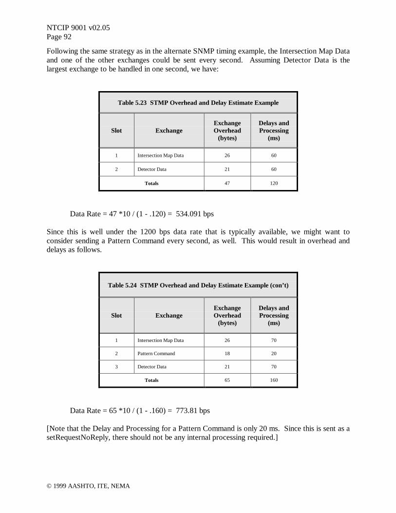
NTCIP 9001 v02.05Page 92
© 1999 AASHTO, ITE, NEMA
Following the same strategy as in the alternate SNMP timing example, the Intersection Map Dataand one of the other exchanges could be sent every second. Assuming Detector Data is thelargest exchange to be handled in one second, we have:
Table 5.23 STMP Overhead and Delay Estimate Example
Slot ExchangeExchangeOverhead
(bytes)
Delays andProcessing
(ms)
1 Intersection Map Data 26 60
2 Detector Data 21 60
Totals 47 120
Data Rate = 47 *10 / (1 - .120) = 534.091 bps
Since this is well under the 1200 bps data rate that is typically available, we might want toconsider sending a Pattern Command every second, as well. This would result in overhead anddelays as follows.
Table 5.24 STMP Overhead and Delay Estimate Example (con’t)
Slot ExchangeExchangeOverhead
(bytes)
Delays andProcessing
(ms)
1 Intersection Map Data 26 70
2 Pattern Command 18 20
3 Detector Data 21 70
Totals 65 160
Data Rate = 65 *10 / (1 - .160) = 773.81 bps
[Note that the Delay and Processing for a Pattern Command is only 20 ms. Since this is sent as asetRequestNoReply, there should not be any internal processing required.]
NTCIP 9001 v02.05Page 93
© 1999 AASHTO, ITE, NEMA
Since 774 bps provides plenty of margin, one could increase the amount of information beingbrought back in the Intersection Map Data. For example, if the intersection had a preemptionsequence, the preemptState - Section 2.7.2.16 could be added. This object could be used toindicate the state or interval of a preemption sequence. Another object that could be added isphaseStatusGroupPhaseNexts - Section 2.2.4.11. This would indicate the next vehicle phase thatis to be serviced at the end of any currently timing phase.
As in the SNMP example, the other exchanges could be mapped in to the third slot on a rotatingbasis as shown in Figure 5.22.

NTCIP 9001 v02.05Page 94
© 1999 AASHTO, ITE, NEMA
6 IMPLEMENTING NTCIP
6.1 Introduction
This chapter describes the various issues related to implementing the NTCIP in a device orcentral system. The primary audiences for this chapter are the system/device developers andsystem implementers. Readers should already be familiar with the concepts presented inChapters 1-4 of this Guide, especially the concepts related to system design and specification aspresented in Chapters 3 and 4.
This chapter contains the following sections:
• Implementation Roadmap- Initial Request- Investigate Issues
- Device and/or System Requirements- How NTCIP Standards Fit Together- Selecting Standards for an Implementation- Selecting Manufacturer Extensions
- Implementation Alternatives- Other Factors
- Stability of the Standard- Support of Amendments- Interpretation Resolution- Client / Developer Understanding- Certification Process- Integration with Other Components- Performance Issues- Maintenance / Future Upgrades
- Development- Delivery / Acceptance Testing
- Unit Testing- Integration Testing- System Testing
- Maintenance• Example Implementation Process• Example Byte Streams
- The NTCIP Database- Encoding the NTCIP Database for Transmission
- Encoding an Object with Its Value- Encoding the SNMP Data Packet- The Transport Profile- The Subnetwork Profile
• Defining New Objects• Examples of Implementation Problems

NTCIP 9001 v02.05Page 95
© 1999 AASHTO, ITE, NEMA
- Protocol Related Issues- Bit and Byte Order- Extended Addresses- Maximum Duration Between Successive Bytes- Response Time- Control Byte- Frame Handling- CRC Algorithm- Invalid Frame- STMP Message Type Byte- Length Values for Variable Message Fields
- Systems Integration Issues- Carriers- Number of Devices on a Channel- MIB Issues
• Development Resources- Web Sites- Sources of Public Domain Software
- NTCIP Exerciser- Field Device Simulator
- Books- Other Resources
This chapter is intended to be germane to all of the NTCIP standards. As such, the concepts arepresented at a high level. However, one detailed example is given at the end of the chapter inorder to explain the concepts more fully.
The reader is warned not to rely on this interpretation of the NTCIP for development purposes.A system or device developer will need to review the relevant NTCIP standards in order toimplement them properly.
This document is updated from time to time to reflect changes in NTCIP. To check whether thisis the current version of this document, access the NTCIP home page on the World Wide Web athttp://www.ntcip.org.
6.2 Implementation Roadmap
There are certain steps that should be taken in any systems development project. It is especiallycritical to follow these steps when developing systems that are intended to meet standards.Figure 6.1 summarizes some of the more important steps that should be followed by anyorganization considering the development of NTCIP software.

NTCIP 9001 v02.05Page 96
© 1999 AASHTO, ITE, NEMA
6.2.1 Initial Request
Software projects are initiated by an individual or organization (client) requesting a certainproduct from a developer. The client and developer may be a part of the same organization ormight represent two distinct organizations. For example, a manager may wish to develop anNTCIP device using internal resources in order to be the first NTCIP compliant device on themarket. Alternatively, the request may come from an agency wishing to procure such a device,even though the device is not currently available on the market. In either case, it is wise toperform a full investigation of the issues surrounding the request prior to submitting theproposal.
6.2.2 Investigate Issues
The developer must ensure that there is an adequate understanding of the request. Some requestsmay be very ambiguous (i.e., "The device shall be NTCIP-compliant."), others may be very
Figure 6.1 Roadmap for Implementing NTCIPInitial
Request MaintenanceDevelopmentStudy
ImplementationAlternatives
SystemTest
IntegrationTest
Delivery andAcceptance
UnitTest
InvestigateIssues
StudyRequirements
SelectStandards
SelectManufacturer
Extensions
ConsiderOther Factors
Stabilityof Standard
Support ofAmendments
InterpretationResolution
Client/DeveloperUnderstanding
CertificationProcess
IntegrationRequirements
PerformanceRequirements
Maintenanceand Upgrades

NTCIP 9001 v02.05Page 97
© 1999 AASHTO, ITE, NEMA
detailed and precise, and some may have precise statements that conflict with each other. Thus,the developer must first perform an investigation to ensure a proper understanding of the client'sneeds. This is then followed by an investigation of how the system may be implemented whilerecognizing the development risks that may be encountered.
It should be realized that this process works best in an iterative fashion. This allows the clientand the developer to work together in developing a list of requirements and a proposal that bestmatches everyone's needs. However, this is not always possible due to the procurementregulations of some organizations.
6.2.2.1 Device and/or System Requirements
The first aspect of the investigation should be to determine the exact requirements for the system.This will often require expanding the original request. For example, if the request is simply foran "NTCIP compliant device", the developer must determine what functionality the device issupposed to support and then determine what NTCIP options might be appropriate.
The developer may also need to modify or limit the original request in order to meet safety,schedule, budget, market or other concerns. For example, the request may be for a signalcontroller and require "support for the full range of all objects." However, for safety and liabilityreasons, the developer may want to develop his software to limit the valid values for the yellowclearance interval to 3.0 to 5.0 seconds. It is important to identify any such variances from therequest as early as possible so that the expectations for the resulting product are properlymanaged.
The result of this effort should be a detailed requirements document with which both the clientand developer can be satisfied. Additional details of this investigation are given below. As aminimum, the document should address those issues identified in Chapter 4 of this Guide.
6.2.2.1.1 How NTCIP Standards Fit Together
Ideally, there would only be one NTCIP standard that met everyone's needs. However, realityrequires a large number of options to meet the unique needs of specific sites. For example, someagencies have a large amount of twisted pair copper that they want to continue to use. Otheragencies are installing new systems and want to take advantage of fiber optic cable and othertechnologies. Likewise, some agencies have fairly simple data exchange needs with fielddevices, whereas other centers need to exchange large amounts of information with other centers.The NTCIP accommodates these various needs by providing a suite of standards, each providingunique features.
NTCIP standards are based on a layered approach that is similar to those used by theInternational Organization for Standardization (ISO) and the Internet community. There are fourprimary levels of the NTCIP stack:

NTCIP 9001 v02.05Page 98
© 1999 AASHTO, ITE, NEMA
• Information – Information Profiles define the meaning of data and messages andgenerally deal with ITS information (rather than information about the communicationsnetwork). This is similar to defining a dictionary and phrase list within a language.These standards are above the traditional ISO seven layer stack.
• Application – Application Profiles define the rules and procedures for exchanginginformation data. The rules may include definitions of proper grammar and syntax of asingle statement as well as the sequence of allowed statements. This is similar tocombining words and phrases to form a sentence or a complete thought and defining therules for greeting each other and exchanging information. These standards are equivalentto the Session, Presentation and Application Layers of the ISO seven layer stack.
• Transport – Transport Profiles define the rules and procedures for exchanging theApplication data between point 'A' and point 'X' on a network. This includes anynecessary routing, message disassembly/re-assembly and network management functions.This is similar to the rules and procedures used by the telephone company to connect tworemotely located phones.
• Subnetwork – Subnetwork Profiles define the rules and procedures for exchanging databetween two 'adjacent' devices over some communications media. This is equivalent tothe rules used by the telephone company to exchange data over a cellular link versus therules used to exchange data over a twisted pair copper wire.
Any data exchange requires the use of one standard taken from each of the four levels. In theory,a profile from one level should be designed such that it can be combined with any profile fromanother level; however, in practice, profiles will often require certain services from other levels.Thus, only certain combinations are desirable and recognized by the NTCIP effort. Thesecombinations are depicted in Figure 6.2.

NTCIP 9001 v02.05Page 99
© 1999 AASHTO, ITE, NEMA
6.2.2.1.2 Selecting Standards for an Implementation
The client may inform the developer which standards to use in the request; however, even in thiscase, the developer must be familiar with the standards enough to ensure that the request isconsistent with the intended purpose of the standard. For example, the CORBA standard is notintended for field device communications using the "object definition standards." If a developerreceives such a request, he should contact the client to ensure that there is an appropriateunderstanding of what is required.
During this phase of the investigation, the developer should also consider the general marketapplicability of the selected standards. For example, if the developer believes that themarketplace will seldom request the selected combination, the bulk of the implementation costswill have to be borne by the one client. Thus, it may be appropriate to suggest a more commoncombination of standards in order to spread the development costs over multiple clients.
Center-to-FieldCenter-to-Center
Plant LevelPlant Level
Figure 6.2 NTCIP Standards Framework
SLIP PPP PMPPFDDI Ethernet
Twisted Pair Telco Line Wireless
V Series Modem FSK Modem
Fiber Coax
UDPTCP
IP
NULL
DATEX TFTP SNMP STMPFTPCORBA
Transport Level
Subnetwork Level
Application Level
Information Level
Transport Level
Application Level
Information Level
Subnetwork Level
Dynamic Objects
ITS Data Model
Files
Data Objects
ATM
SONET
ITS Data Dictionary
ITS Message SetsReference Model
* Not all combinations between the Subnetwork and Plant Levels are feasible

NTCIP 9001 v02.05Page 100
© 1999 AASHTO, ITE, NEMA
6.2.2.1.3 Selecting Manufacturer Extensions
Finally, the developer must determine whether or not the standard supports all of the featuressupported by the manufacturer's device. The NTCIP has been explicitly designed to allow forinnovations and it is recognized that the NTCIP standards do not currently define standardizedobjects for every feature of every device. Thus, the developer must determine if there are specialfeatures of the subject device that are not standardized by the NTCIP. If such features arepresent, then the developer will need to determine precisely how these features will be supportedwithout conflicting with the standardized implementations. Usually, this is simply definingadditional objects under a developer specific node. Once defined, the developer may want topublish these objects to the transportation community in order to promote this design as thedefacto standard for the given feature.
6.2.2.2 Implementation Alternatives
Once there is a clear understanding of the project requirements, the developer can investigateways to implement the desired features. For example, the developer may be able to acquire off-the-shelf software to minimize the effort required to implement the features. A layered designwill minimize the effort required to maintain the code and to implement different profiles in thefuture. However, these benefits may impose other constraints on the system.
The NTCIP has used widely recognized standards whenever possible. For example, the NTCIPstandards reference the Transmission Control Protocol (TCP), Internet Protocol (IP), SimpleNetwork Management Protocol (SNMP), Common Object Request Broker Architecture(CORBA), and High Level Data Link Control Protocol (HDLC) standards to name just a few.
In many cases, the private industry has developed off-the-shelf tools to aid system developers inimplementing these protocols. Being aware of what products are available and for what costswill allow the developer to provide a more realistic estimate of development costs. For example,most developers use an off-the-shelf implementation of TCP/IP rather than creating their own.Standards for which there are known products include:
• File Transfer Protocol (FTP)• Trivial File Transfer Protocol (TFTP)• SNMP• CORBA• Data Exchange in ASN.1 (DATEX-ASN)• TCP/IP and UDP/IP• Point-to-Point Protocol (PPP)• Ethernet
While off-the-shelf software can save a considerable amount of development time and greatlysimplify maintenance of the software; it may not always provide the most efficientimplementation. Off-the-shelf software has generally been designed in a very layered fashion foreasy maintenance and fully generic use; however, real-time system performance can frequently

NTCIP 9001 v02.05Page 101
© 1999 AASHTO, ITE, NEMA
be improved by violating the rules of a true layered design and by embedding customized codefor a specific purpose. The system developer should consider the benefits and detriments of eachapproach before determining the development approach and cost estimate.
It should also be recognized that the availability of off-the-shelf tools may affect the selection offeatures to be included in the requirements document.
6.2.2.3 Other Factors
There may be a variety of other factors that may need to be considered in order to finalize aproposal. Each of these issues may impact the proposed budget, schedule, and/or scope.Therefore, they should be explicitly addressed in the proposal in order to manage expectations.Without the management of expectations early in the process, a product, which the developerbelieves is compliant, may be perceived to be lacking by the client. A sample of these issues isprovided in the following subclauses.
6.2.2.3.1 Stability of the Standard
The NTCIP standards are still relatively new and all standards are subject to amendments.Amendments typically result from developers attempting to implement the subject standard andrecognizing either a technical problem with the specification or ambiguous wording. Thus, newstandards are frequently amended to solve these problems and the standards become more andmore stable over time. Thus, from a developers perspective, there is greater risk in implementingnew standards; however, typically the first manufacturers to implement are the manufacturerswho establish the greatest market share. Thus, these trade-offs must be considered in anyimplementation.
6.2.2.3.2 Support of Amendments
Because the standards are relatively new, the developer must consider what will happen if anamendment to the standard is approved during the development period of the product. As ageneral rule, it may be difficult to support amendments that are made after the product design isfinalized and coding has begun. However, many times, a draft amendment may be presentduring design and the issues identified in the draft can be incorporated. In any case, the proposalshould explicitly state whether or not amendments will be included for the proposed price andwhether or not there is a cut-off date for such amendments.
6.2.2.3.3 Interpretation Resolution
If a developer is implementing a relatively new standard, he should ensure that there is a clearunderstanding of how interpretation problems will be addressed. For example, one couldpropose that any interpretation compliant with the wording is valid for acceptance. This would
NTCIP 9001 v02.05Page 102
© 1999 AASHTO, ITE, NEMA
minimize the risk undertaken by the developer, but may not result in a product that isinteroperable with other "standard" devices. Another approach would be to have the respectiveNTCIP Working Group provide an interpretation of the standard; this would increase the riskassumed by the developer but would also increase the probability for interoperability.
6.2.2.3.4 Client/Developer Understanding
Another factor to consider is whether or not the client has realistic expectations. While theNTCIP provides a standardized interface that is flexible enough to meet various needs, it may bemore bandwidth intensive than what the client's previous systems and/or it may use a slightlydifferent database design. It is important to make sure that the client has realistic expectations atthe start of the project in order to ensure that the project will be perceived as a success. Athorough understanding of the expectations on the part of both the client and developer isimportant to the success of any project.
6.2.2.3.5 Certification Process
The developer must also consider the certification process for the product. While a rigidcertification process will undoubtedly provide a greater assurance to the client, it will alsoincrease costs. These costs are especially important to consider if the developer is responsiblefor any testing costs (e.g., through hiring an independent lab).
6.2.2.3.6 Integration with other components
The developer may also be required to ensure that his device works with other componentswithin a larger system. Such integration may reveal problems that do not appear during productcertification and thus may also affect the project costs.
6.2.2.3.7 Performance Issues
The developer should also realize that the flexibility of NTCIP also comes at the price of a morecomplex system than the industry has traditionally used. Therefore, the system may requiremore sophisticated processors or better communication facilities than traditional systems in orderto achieve the same performance level (e.g., response times, etc.). If the developer overlooksthese issues at the design time, there could be significant costs imposed at the end of the projectin order to provide the necessary performance. The client should also be informed ofperformance tradeoffs.

NTCIP 9001 v02.05Page 103
© 1999 AASHTO, ITE, NEMA
6.2.2.3.8 Maintenance / Future Upgrades
A final issue to consider is whether or not the client desires extended maintenance or futureupgrades. Such services may be very appropriate given that the standards may change based onother deployment projects; but clearly such a service will increase the costs associated with theproject.
6.2.3 Development
If the proposal is accepted, the development phase will begin. This will include finalizing thedevelopment approach, building the prototypes and internally testing the units.
6.2.4 Delivery / Acceptance Testing
Once the developer is satisfied with the quality of his implementation, it is ready for delivery tothe client. At this point, the client will perform an acceptance test. The type of acceptance testshould be specified in the proposal process as this may affect the cost of the delivered product. Itshould be realized that the NTCIP is a very complex set of standards and it is impractical toperform comprehensive testing. However, well designed test plans can be produced to provide ahigh level of confidence for a reasonable cost.
In general, there are three levels of testing: unit testing, integration testing, and system testing.
6.2.4.1 Unit Testing
Unit testing focuses on comparing an implementation against the standard. This may beperformed by inspecting the code or with the use of "proven" software to send test messages tothe device. This process should be formalized by documenting a specific test procedure that willbe followed and during the test, the result of each step of the procedure should be recorded.
Unit testing provides a basic level of assurance that a product is compliant to a standard. Manytimes, the test plan will be designed such that the failure of one procedure will provide a clearindication of what problem resides within the implementation; thereby minimizing the cost offinding the 'bug'. A device that fails such a test plan would almost certainly not be able tointeroperate with other systems. A device that passes such a test has a reasonable probability ofinteroperating.
6.2.4.2 Integration Testing
Integration testing consists of connecting two or more devices together and having themexchange data. Assuming the individual devices have previously passed a sufficiently designedunit test plan and the two devices support the same features, the devices should integrate together

NTCIP 9001 v02.05Page 104
© 1999 AASHTO, ITE, NEMA
fairly easily. However, there are a few problems that may arise during this phase. Examplesinclude two different interpretations of a specific requirement (typically a problem of newerstandards) and problems related to system timing between the two implementations.
In theory, the unit test should be thorough enough to prevent any problems in integration testing;however, the integration testing provides a higher level of confidence that nothing has beenoverlooked.
6.2.4.3 System Testing
A final level of testing is system testing. At this level, each device on the system is integratedtogether to form the final system. This level of testing could identify problems such as modemcarriers being left on (i.e., preventing other devices from talking) or system timing issues (e.g.,too many signals on a channel to maintain a desired once-per-second poll rate).
Once again, in theory, devices that successfully pass unit testing and integration testing shouldpass this level as well as long as the system was properly designed. However, the final check isonly provided when this test is performed and it is not infrequent that problems arise at thisstage.
6.2.5 Maintenance
The developer should also be aware of any requirements for maintenance and upgrades as thesewill affect the overall costs of the project. In general, it should be recognized that the NTCIPstandards are still relatively new and thus changes may occur to the standards. Further, as thereare relatively few implementations available, ambiguities may still be discovered in the standardand the standards may be modified in order to correct these problems. Any such change mayrequire a modification to deployed equipment if the equipment is to maintain compatibility withthe new version of the standard.
6.3 Example Implementation Process
This section provides an example of the various decisions that must be made during animplementation project. In the following example represents a procedure that a manufacturer ordeveloper might use to develop an NTCIP compliant device. In this case, the device is adynamic message sign.
6.3.1 The Request
For the purposes of this example, we will assume that the client has issued an Invitation For Bidfor a dynamic message sign and controller (DMS) containing the following statements:
NTCIP 9001 v02.05Page 105
© 1999 AASHTO, ITE, NEMA
A. The DMS shall be a full matrix capable of displaying three lines of text with 20 charactersper line when 18 inch characters are utilized. Full matrix display shall be capable ofdisplaying other size characters and other number of lines depending on the height ofcharacters utilized. The sign shall be designed to provide 2 pixels of spacing between lines oftext when displaying the characters and lines of text as indicated herein.
B. The DMS shall be provided with a temperature sensor to monitor the interior temperature ofthe sign.
C. The DMS shall be capable of the following types of displays.1. Signs shall be able to display each line as either static or flashing, as described below.
a) Static Message - The line shall be displayed constantly on the sign face until the signcontroller is instructed to do otherwise.
b) Flashing Message - A selected line shall be displayed and blanked alternately atdurations separately controllable in 0.5-second increments.
2. The DMS shall be capable of displaying up to three different pages (each page consistingof up to three lines of text) alternately at duration’s separately controllable in 0.5-secondincrements.
3. The sign shall be able to display text as centered, right justified, or left justified4. The sign shall be able to display a message in a specific font (e.g., single-stroke or double
stroke).5. In the event of communication errors or controller lock-ups, the sign shall retain the
current message. In the event of a power failure, sign shall display the current messageupon restoration of power.
D. The DMS shall display a message composed of any combination of the following charactersand shapes:1. "A" thru "Z"- All upper case letters.2. "0" thru "9"- All decimal digits.3. A blank or space.4. Punctuation marks shown in brackets [. , ! ? - : ; " ' / ( ) ]5. Special characters shown in brackets [# & * + < >]6. graphic displays
E. All communications between the DMS and central computer shall be NTCIP compliant inone of the following modes, which shall be user selectable:1. Polled Operation in which the sign controller informs the central computer of its current
status in response to a query from the central computer; or;2. Event-Driven Operation in which the sign controller not only responds to queries from
the central computer but also calls the central computer by telephone whenever it detects:restoration of AC power at the sign controller and/or internal DMS temperature exceedsprogrammed safety limit. If the line is busy, it shall retry the call at an interval thatcan be selected by the operator until it connects with the central computer.
F. The DMS shall contain a computer-readable time-of-year clock with a lithium batterybackup. Battery shall keep the clock operating properly for at least 10 years without externalpower. Clock shall automatically adjust for daylight saving time and leap year throughhardware or software or a combination of both. It shall be set by the sign controller'smicroprocessor. Clock shall be accurate to within 1 minute per month.
NTCIP 9001 v02.05Page 106
© 1999 AASHTO, ITE, NEMA
G. The DMS shall be provided with an eight character (minimum) password, for access to signcontroller.
H. In the absence of instructions to the contrary from the remote control port, the DMS shallimplement a display selected from those stored in its memory based upon date and time asspecified in the schedule.
I. The DMS shall incorporate fail-safe procedures to check messages received and shall notchange a message stored in memory, the display currently on the sign, the schedule stored inmemory, or the current time unless the message is received correctly.
J. The DMS shall associate a priority level with each message. If the priority status is higherthan the status of the message that it is to replace, the new message shall be posted.
K. The DMS shall include a system which shall sense the background ambient light level andprovide a minimum of sixteen field adjustable intensities (dimming).
L. An 8 byte ID code shall be assignable to each DMS.
6.3.2 The Investigation
While the above request provides a fair amount of detail as to the required functionality of thesign, the information is not presented in a format that directly relates to NTCIP requirements andthere are several issues on which the request is silent. The first task of the investigation is todetermine exactly what the requirements are and to then investigate the other related issues. Thediscussion presented here only focuses on the NTCIP issues; however, a real investigation wouldclearly have to investigate hardware issues as well.
6.3.2.1 Requirements
The first task is to provide an interpretation of each requirement of the request. In this case,there is a fair description of the desired functionality, thus, this task is a matter of mapping thefunctions to specific NTCIP features. In other cases, the developer may have to work moreclosely with the client to develop the functional requirements. Once the initial interpretation isperformed, the developer may have a list of questions for the client.
6.3.2.1.1 Interpretation
The list below interprets the above requirements into specific NTCIP requirements. Normal textindicates the original statement. Text in italics indicates the NTCIP interpretation. Text in boldindicates significant statements that may impact costs and/or may impact the user's expectations.
A. The DMS shall be a full matrix capable of displaying three lines of text with 20 charactersper line when 18 inch characters are utilized. Full matrix display shall be capable ofdisplaying other size characters and other number of lines depending on the height ofcharacters utilized. The sign shall be designed to provide 2 pixels of spacing between lines of
NTCIP 9001 v02.05Page 107
© 1999 AASHTO, ITE, NEMA
text when displaying the characters and lines of text as indicated herein. The DMS shall be afull matrix display consisting of 120 pixels wide by 27 pixels high. Pixels shall be evenlyspaced both vertically and horizontally. A 5 x 7 pixel matrix shall form a standard fixedwidth 18" high character. The DMS shall support five fonts, as defined by the NTCIP fonttable.
B. The DMS shall be provided with a temperature sensor to monitor the interior temperature ofthe sign. The Temperature Status Conformance Group shall be supported. This alsorequires two additional sensors: one to monitor the ambient temperature and the other tomonitor controller cabinet temperature.
C. The DMS shall be capable of the following types of displays.1. Signs shall be able to display each line as either static or flashing, as described below.
This shall be achieved through the use of the 'fl' MULTI Tag.a) Static Message - The line shall be displayed constantly on the sign face until the sign
controller is instructed to do otherwise.b) Flashing Message - A selected line shall be displayed and blanked alternately at
durations separately controllable in 0.5-second increments.2. The DMS shall be capable of displaying up to three different pages (each page consisting
of up to three lines of text) alternately at duration’s separately controllable in 0.5-secondincrements. This shall be achieved through the use of the 'np' and 'p' MULTI Tags.
3. The sign shall be able to display text as centered, right justified, or left justified. Thisshall be achieved through the use of the 'jl' MULTI Tag.
4. The sign shall be able to display a message in a specific font (e.g., single-stroke or doublestroke). This shall be achieved through the use of the 'fo' MULTI Tag.
5. In the event of communication errors or controller lock-ups, the sign shall retain thecurrent message. In the event of a power failure, sign shall display the current messageupon restoration of power. This shall be achieved by storing the currentBuffer row of themessage table in non-volatile memory and configuring the appropriate Default Messageobjects to point to the currentBuffer. This is one interpretation of the standards.
D. The DMS shall display a message composed of any combination of the following charactersand shapes: These shall be stored in the default fonts as their respective ASCII charactercodes. Other character codes can be used for graphics. There will also be one font reservedfor graphics (true graphics are not currently standardized by NTCIP). Alternatively, amanufacturer specific graphic capability can be provided.1. "A" thru "Z"- All upper case letters.2. "0" thru "9"- All decimal digits.3. A blank or space.4. Punctuation marks shown in brackets [. , ! ? - : ; " ' / ( ) ]5. Special characters shown in brackets [# & * + < >]6. graphic displays
E. The DMS shall permit the communication with an NTCIP compliant central computer ineither of the following modes which shall be user selectable: The DMS shall provideminimal support for the PPP Subnetwork Profile (i.e., Dial-up Modem, RS-232, PPP), theInternet Transport Profile (i.e., UDP/IP), the STMF Application Profile (i.e., SNMP), andthe DMS Information Profile (as defined in Sections 4 and 5 of TS 3.6). The temperature

NTCIP 9001 v02.05Page 108
© 1999 AASHTO, ITE, NEMA
safety limit shall be a manufacturer specific object and the notification shall be achievedthrough a manufacturer specific trap.1. Polled Operation in which the sign controller informs the central computer of its current
status in response to a query from the central computer; or;2. Event-Driven Operation in which the sign controller not only responds to queries from
the central computer but also calls the central computer by telephone whenever it detects:restoration of AC power at the sign controller and/or internal DMS temperature exceedsprogrammed safety limit. If the line is busy, it shall retry the call at an interval whichcan be selected by the operator until it connects with the central computer.
F. The DMS shall contain a computer-readable time-of-year clock with a lithium batterybackup. Battery shall keep the clock operating properly for at least 10 years without externalpower. Clock shall automatically adjust for daylight saving time and leap year throughhardware or software or a combination of both. It shall be set by the sign controller'smicroprocessor. Clock shall be accurate to within 1 minute per month. The sign shallsupport the globalTime, globalTimeDifferential, and globalDaylightSavings parameters.
G. The DMS shall be provided with an eight character (minimum) password, for access to signcontroller. The DMS shall support the security (community name) objects defined in theamendment to TS 3.4. This password will also be required when accessing the controllerlocally.
H. In the absence of instructions to the contrary from the remote control port, the DMS shallimplement a display selected from those stored in its memory based upon date and time asspecified in the schedule. The DMS shall support the Timebase Event Schedule conformancegroup from TS 3.4 and the Scheduling conformance group from TS 3.6.
I. The DMS shall incorporate fail-safe procedures to check messages received and shall notchange a message stored in memory, the display currently on the sign, the schedule stored inmemory, or the current time unless the message is received correctly. The DMS shallprovide this feature by using the CRC-16 algorithm of PPP.
J. The DMS shall associate a priority level with each message. If the priority status is higherthan the status of the message that it is to replace, the new message shall be posted. TheDMS shall use the run-time and activation priorities as identified in TS 3.6.
K. The DMS shall include a system which shall sense the background ambient light level andprovide a minimum of sixteen field adjustable intensities (dimming). The DMS shall supportthe Illumination and Brightness control conformance group.
L. An 8 byte ID code shall be assignable to each DMS. Each DMS will be associated with anIPv6 address in addition to the IPv4 address and physical addresses that it will support.
6.3.2.1.2 Questions Arising from Requirements Review
During the above analysis, there were three significant issues that should ideally be clarifiedprior to providing a bid estimate. However, in some cases it may not be possible to ask suchquestions. In these cases, the developer may wish to prepare a bid that documents other options.

NTCIP 9001 v02.05Page 109
© 1999 AASHTO, ITE, NEMA
The three questions that arose from this analysis are:
• How many fonts must the sign support?• Should graphics be handled as a font or as a manufacturer specific feature?• Is support for subnetworks other than PPP required?
A second iteration through this process would include questions arising from the text below,namely:
• How will the sign be tested to ensure compliance?• Who is going to supply the central software?• Are there any other devices in the system?• What are the performance requirements of the system?• Is the developer expected to provide maintenance of the software and/or upgrade the
software if the standards change? If so, until what date?• How many messages must the sign support and of what type?
6.3.2.2 Implementation Alternatives
Once the initial requirements are known, the developer can determine the best approach todeveloping the system; this in turn will allow the developer to start estimating the costsassociated with the project.
Products are readily available from multiple vendors for a standard implementation of SNMP,UDP/IP, and PPP; thus, in this case, the developer would likely choose to use a great deal of off-the-shelf software. This would allow the developer to focus on the actual functionality of theobjects rather than spending a large amount of time on the protocols.
6.3.2.3 Other Factors
As mentioned above, there are a variety of other factors to consider as well. The following textdescribes how these factors might affect the example project.
6.3.2.3.1 Stability of the Standard
In this case, the developer will have to implement the following standards:
• PPP Subnetwork Profile, which includes- AT Command Set- RS 232- PPP- LCP- CHAP

NTCIP 9001 v02.05Page 110
© 1999 AASHTO, ITE, NEMA
• Internet Transport Profile, which includes- UDP- IP
• STMF Application Profile, which includes- SNMP- BER
• Global Object Definitions• Object Definitions for Dynamic Message Signs
These standards are somewhat stable, but could change to some degree. The standardsreferenced by these standards (i.e., the protocols) are widely deployed and are very stable.
6.3.2.3.2 Support of Amendments
Given this design, the developer would probably want to state that the project will use off-the-shelf software for the protocols and will be compliant with the current version of the Profiles.Given the stability of these base standards, this design should be fully compatible with the finalversion of the Profile documents. If, however, amendments are made to the profiles that are notcompatible to the traditional use of the base standards, additional costs may be incurred.
The developer would need to develop the software for the objects internally. As such, thedeveloper would probably indicate that he will support all defined features and all approvedamendments up to a certain date (perhaps six months after award). If an amendment is approvedafter this date, additional costs may be incurred.
6.3.2.3.3 Interpretation Resolution
In this case, the developer would probably want protocol issues to be resolved by the Internetcommunity and object definitions to be resolved by the NTCIP community. Thus, the proposalshould include a statement indicating that the relevant working group shall be contacted toprovide any necessary clarification of the standard. If the resolution is simply a clarification anddoes not require a normative change to the standard, the decision of the working group shall beimplemented. If the decision results in an effort to amend the standard and the amendment is notapproved by the indicated date, the client and developer will negotiate what the appropriatesolution might be and how that solution might impact the schedule and budget of the project.
6.3.2.3.4 Client / Developer Understanding
Given the initial set of requirements provided by the client, it is likely that the client is onlyaware of the NTCIP and is unfamiliar with the details. Thus, the developer should budgetresources during the project to ensure that he is able to properly manage expectations. This mayinclude a meeting during the initial stages of the project to clearly present the features of the endproduct and how this may be different than what the client expects.

NTCIP 9001 v02.05Page 111
© 1999 AASHTO, ITE, NEMA
6.3.2.3.5 Certification Process
The initial requirements did not indicate any certification process. However, it is likely in thedeveloper's best interest to indicate what sort of compliance testing would be appropriate. In thecase of this project, the proposal might suggest that the developer also prepare a test plan, to beapproved by the client, and the test will be performed in front of the client.
6.3.2.3.6 Integration with Other Components
The initial requirements did not indicate whether this sign would be integrated with othercomponents, but one would assume that a management station would be used. Thus, thedeveloper may wish to suggest that the procurement will include a central system to control thesign.
6.3.2.3.7 Performance Issues
The original specification did not include any requirement for performance. The developer maywant to provide a statement in the proposal that the sign will produce a response to a get globaltime request within one second and a set activate message request within two seconds (measuredfrom last byte in to first byte out). However, ideally, the client should specify the performancerequirements [this can be an important issue for traffic signal systems].
6.3.2.3.8 Maintenance / Upgrades
The initial requirements are silent as to maintenance and upgrades. The developer may decide tominimize risks and not include any such features in the proposal, or the developer may decidethat the product will have to be maintained for other clients anyway and thus include the estimatein the proposal. In the latter case, the developer would likely want to encourage the client toinclude maintenance and upgrades in the requirements for the bid by asking a question to thateffect.
6.3.3 Proposal
Once all of these issues are resolved, the developer is able to prepare a proposal. For thisexample, the following text may be included in the proposal.
Display Requirements
The DMS display shall be full matrix and contain 120 pixels wide by 27 pixelshigh. The pixels shall be evenly spaced both horizontally and vertically.

NTCIP 9001 v02.05Page 112
© 1999 AASHTO, ITE, NEMA
The display will be configurable to support different size fonts and the number oflines supported shall be determined based on the selected font. When displaying a5x7 font, a character shall be 18" high and the sign will display 3 lines, eachseparated by two pixels, with 20 characters per line, each separated by one pixel.
The sign shall be equipped with three temperature sensors: one for the interior ofthe sign, one for the interior of the cabinet, and one for the ambient airtemperature.
An internal clock shall be provided to support the globalTime object. It shallhave a lithium battery backup, which will last a minimum of ten years. Thecontroller shall adjust for daylight savings (according to the NTCIP mechanisms)and leap years. The clock shall be accurate to within one minute per month.
The sign shall include a system of light sensors and adjust theillumination/brightness according to the mechanisms defined in TS 3.6.
NTCIP Functional Requirements
The DMS shall support the following NTCIP conformance groups.• Configuration, as defined in NEMA TS 3.4-1996 and Amendment 1• Time Management, as defined in NEMA TS 3.4-1996 and Amendment 1• Timebase Event Schedule, as defined in NEMA TS 3.4-1996 and
Amendment 1• Security, as defined in NEMA TS 3.4 Amendment 1• Sign Configuration, as defined in NEMA TS 3.6-1997• Font Configuration, as defined in NEMA TS 3.6-1997• Message Table, as defined in NEMA TS 3.6-1997• Sign Control, as defined in NEMA TS 3.6-1997• Default Message Control, as defined in NEMA TS 3.6-1997• MULTI Error Control, as defined in NEMA TS 3.6-1997• Illumination/Brightness Control, as defined in NEMA TS 3.6-1997• Scheduling, as defined in NEMA TS 3.6-1997• Status Error, as defined in NEMA TS 3.6-1997• Temperature Status, as defined in NEMA TS 3.6-1997
In addition, the sign will support the following objects, as defined in NEMA TS3.6-1997:
• defaultFlashOn• defaultFlashOff• defaultFont• defaultJustificationLine• defaultPageOnTime• defaultPageOffTime
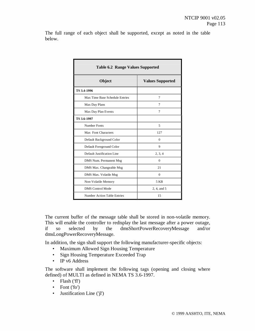
NTCIP 9001 v02.05Page 113
© 1999 AASHTO, ITE, NEMA
The full range of each object shall be supported, except as noted in the tablebelow.
Table 6.2 Range Values Supported
Object Values Supported
TS 3.4-1996
Max Time Base Schedule Entries 7
Max Day Plans 7
Max Day Plan Events 7
TS 3.6-1997
Number Fonts 5
Max Font Characters 127
Default Background Color 0
Default Foreground Color 9
Default Justification Line 2, 3, 4
DMS Num. Permanent Msg 0
DMS Max. Changeable Msg 21
DMS Max. Volatile Msg 0
Non-Volatile Memory 5 KB
DMS Control Mode 2, 4, and 5
Number Action Table Entries 15
The current buffer of the message table shall be stored in non-volatile memory.This will enable the controller to redisplay the last message after a power outage,if so selected by the dmsShortPowerRecoveryMessage and/ordmsLongPowerRecoveryMessage.
In addition, the sign shall support the following manufacturer-specific objects:• Maximum Allowed Sign Housing Temperature• Sign Housing Temperature Exceeded Trap• IP v6 Address
The software shall implement the following tags (opening and closing wheredefined) of MULTI as defined in NEMA TS 3.6-1997.
• Flash ('fl')• Font ('fo')• Justification Line ('jl')
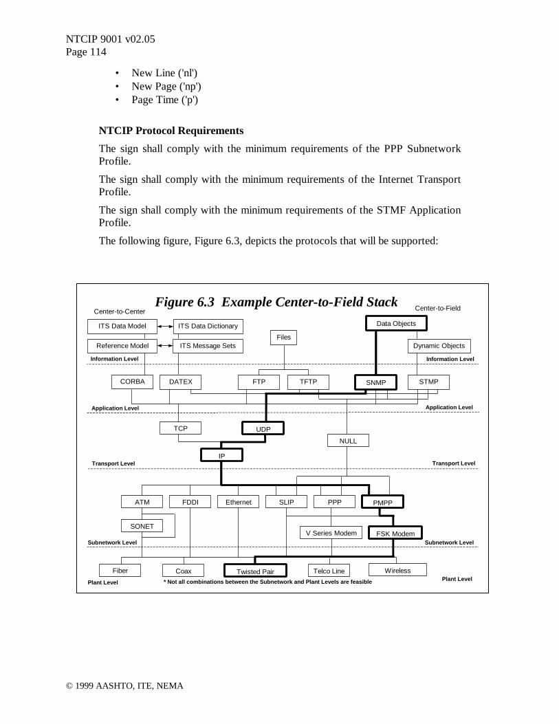
NTCIP 9001 v02.05Page 114
© 1999 AASHTO, ITE, NEMA
• New Line ('nl')• New Page ('np')• Page Time ('p')
NTCIP Protocol Requirements
The sign shall comply with the minimum requirements of the PPP SubnetworkProfile.
The sign shall comply with the minimum requirements of the Internet TransportProfile.
The sign shall comply with the minimum requirements of the STMF ApplicationProfile.
The following figure, Figure 6.3, depicts the protocols that will be supported:
Center-to-Center
Plant LevelPlant Level
Figure 6.3 Example Center-to-Field Stack
SLIP PPP PMPPFDDI Ethernet
Twisted Pair Telco Line Wireless
V Series Modem FSK Modem
Fiber Coax
UDPTCP
IP
NULL
DATEX TFTP SNMP STMPFTPCORBA
Transport Level
Subnetwork Level
Application Level
Information Level
Transport Level
Application Level
Information Level
Subnetwork Level
Dynamic Objects
ITS Data Model
Files
Data Objects
ATM
SONET
ITS Data Dictionary
ITS Message SetsReference Model
Center-to-Field
* Not all combinations between the Subnetwork and Plant Levels are feasible

NTCIP 9001 v02.05Page 115
© 1999 AASHTO, ITE, NEMA
Initial Configuration
The controller will be shipped with a four standard font sets: an 18" (5x7) singlestroke, an 18" double stroke, a 13" (3 or 4 x5) single stroke, and a 36" doublestroke. The stored characters shall include all of the upper case letters (A-Z),digits (0-9), a blank, and the following marks: [. , ! ? - : ; " ' / ( ) # & * + < > $ ].All characters will be stored according to their ASCII character codes. Thecharacter entries for all other ASCII character codes shall be left empty for theuser to define. The fifth font shall contain a sampling of common graphics.
Acceptance
A test plan shall be provided to the client for approval. Upon delivery of the sign,the test plan will be performed in the presence of the client to demonstrateconformance to the standard.
Maintenance / Upgrades
This contract does not include maintenance or upgrade support.
6.4 Example Byte Streams
This section will provide the reader with a basic understanding of how the NTCIP works in acenter-to-field environment.
6.4.1 The NTCIP Database
Transportation devices need to store and communicate constants, parameters, and collected data.Examples include minimum cycle time for a traffic signal, text for a dynamic message sign,vehicles per hour for a count station, and current wind speed from a weather station.
NTCIP is intended for many types of transportation devices, each with different databaserequirements. NTCIP relies on the SNMP approach to database management. SNMP uses anindustry-standard get/set paradigm to read and write data in a database. Data elements in thedatabase are called “managed objects” or just “objects” for short. The database is a group ofrelated objects and is called a “management information base” or MIB. The entity that managesthe MIB within a device is called an agent. The concept is that a management application sendsmessages to the agent to fetch or modify the values of objects stored within the MIB. WhenMIB values change, the transportation device responds as defined in its programming. The agentworks at the application layer in the protocol, but is itself not the application. The agent does notcare whether the MIB represents a traffic controller or dynamic message sign or any otherdevice.
STMP works in the same way as does SNMP and uses the same objects. STMP simply providesa more bandwidth efficient, but more processor intensive, solution to the same problem.

NTCIP 9001 v02.05Page 116
© 1999 AASHTO, ITE, NEMA
An object is a type of data. Within an agent, one or more instances of the object may exist.Different instances are identified by their index, as discussed below. An object instance must betransported as a whole. As an example, an object may define the current time, say 12:15:30.Since this object is defined as hours, minutes and seconds, it can not be used to transport justseconds. Alternatively, time could be defined as three separate objects, one each for hours,minutes, and seconds; in this case, a request could deal with any one of the three objects orsimultaneously access all three. A third alternative would be to define both of theserepresentations of time (for a total of four objects). It may be convenient to have access todifferent forms of the same data in the same MIB but it is not very efficient, since extra objectsrequire more computer memory. Thus, when designing objects, the designer must consider thetrade-offs of each approach.
To standardize some of the commonly needed objects, the NTCIP defines a global objects MIBmodule. The global MIB module contains definitions of commonly needed objects that are basicto the NTCIP, such as the name and versions of the MIBs supported by an agent.
A MIB and its objects are defined using Abstract Syntax Notation One (ASN.1). "Abstractsyntax" means that the manner used to define the data is independent of the procedure forencoding the data into binary form. The MIB is a text document that can be read by a humanand compiled by computer. A management application must have a copy of the MIB employedby the managed agent. The MIB is transferred to a management application via a text file on afloppy disk. This is usually performed when the device is first installed. However, othermethods could be used for MIB transfer.
Example 6.1:
Consider the example above where the device includes a clock. The managementapplication will need to set the clock periodically to ensure that all devices aresynchronized. The MIB defined in Global Object Definitions (TS 3.4-1996 andAmendment 1), includes an object called "globalTime." Below is the ASN.1definition of this object.
globalTime OBJECT-TYPESYNTAX CounterACCESS read-writeSTATUS mandatoryDESCRIPTION “The current time in seconds since the epoch 00:00:00(midnight) January 1, 1970 UTC (a.k.a. Zulu).”::={globalTimeManagement 1}
The first line is the name of the object, followed by the formal invocation of the OBJECT-TYPEmacro.
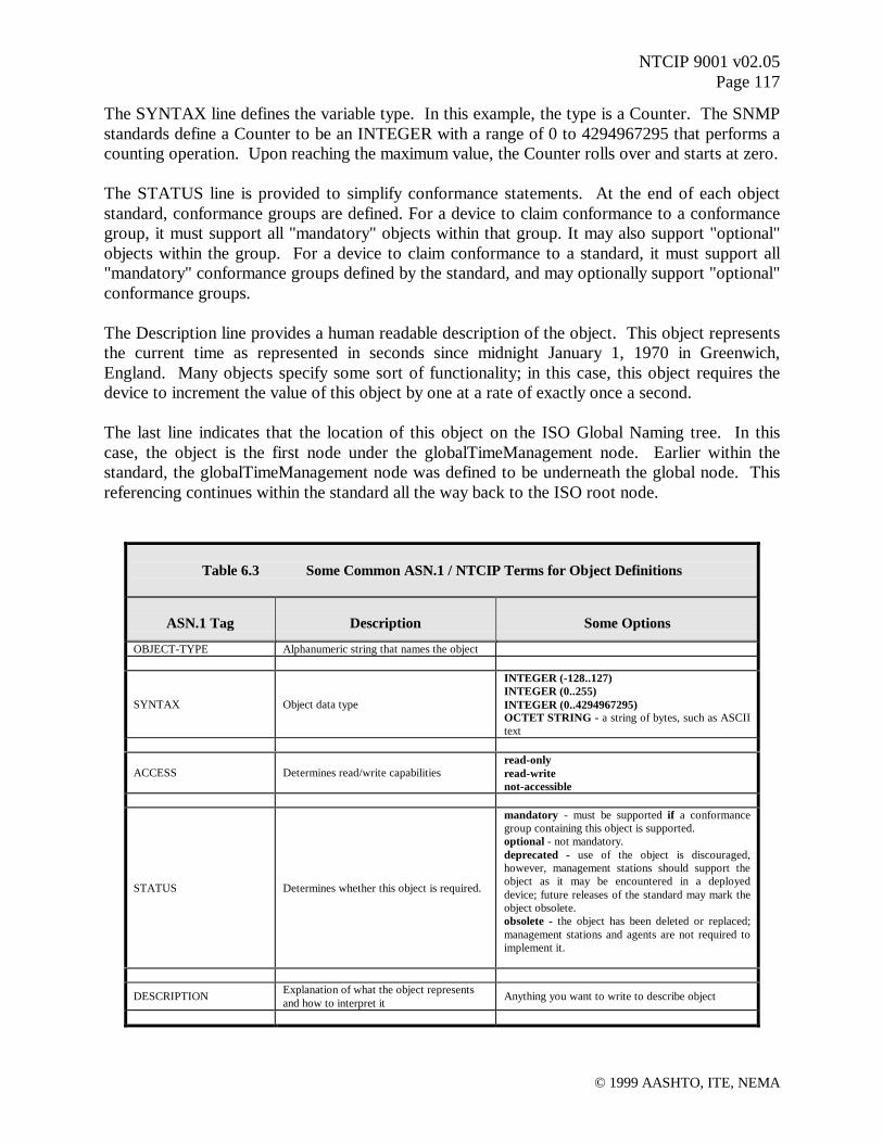
NTCIP 9001 v02.05Page 117
© 1999 AASHTO, ITE, NEMA
The SYNTAX line defines the variable type. In this example, the type is a Counter. The SNMPstandards define a Counter to be an INTEGER with a range of 0 to 4294967295 that performs acounting operation. Upon reaching the maximum value, the Counter rolls over and starts at zero.
The STATUS line is provided to simplify conformance statements. At the end of each objectstandard, conformance groups are defined. For a device to claim conformance to a conformancegroup, it must support all "mandatory" objects within that group. It may also support "optional"objects within the group. For a device to claim conformance to a standard, it must support all"mandatory" conformance groups defined by the standard, and may optionally support "optional"conformance groups.
The Description line provides a human readable description of the object. This object representsthe current time as represented in seconds since midnight January 1, 1970 in Greenwich,England. Many objects specify some sort of functionality; in this case, this object requires thedevice to increment the value of this object by one at a rate of exactly once a second.
The last line indicates that the location of this object on the ISO Global Naming tree. In thiscase, the object is the first node under the globalTimeManagement node. Earlier within thestandard, the globalTimeManagement node was defined to be underneath the global node. Thisreferencing continues within the standard all the way back to the ISO root node.
Table 6.3 Some Common ASN.1 / NTCIP Terms for Object Definitions
ASN.1 Tag Description Some Options
OBJECT-TYPE Alphanumeric string that names the object
SYNTAX Object data type
INTEGER (-128..127)INTEGER (0..255)INTEGER (0..4294967295)OCTET STRING - a string of bytes, such as ASCIItext
ACCESS Determines read/write capabilitiesread-onlyread-writenot-accessible
STATUS Determines whether this object is required.
mandatory - must be supported if a conformancegroup containing this object is supported.optional - not mandatory.deprecated - use of the object is discouraged,however, management stations should support theobject as it may be encountered in a deployeddevice; future releases of the standard may mark theobject obsolete.obsolete - the object has been deleted or replaced;management stations and agents are not required toimplement it.
DESCRIPTION Explanation of what the object representsand how to interpret it Anything you want to write to describe object

NTCIP 9001 v02.05Page 118
© 1999 AASHTO, ITE, NEMA
Table 6.3 lists some common ASN.1 terms used for object definitions. Since this is anincomplete list, refer to ISO 8824 and the NTCIP documents for more information. The NTCIPalso defines additional limitations to ASN.1. These limitations are defined in a section called theNEMA Structure and Identification of Management Information (NEMA_SMI). TheNEMA_SMI is not a MIB but is added to all NTCIP MIBs.
The ASN.1 macro language is very powerful, even with the restrictions imposed by SNMP. AMIB may define a new syntax by combining basic (primitive) data types. Likewise, a MIB candefine a one or multi-dimensional table using the SEQUENCE operator. Default values andranges for objects can also be defined in the MIB. The robustness of the ASN.1 language allowsfor the modeling of virtually any database likely to be encountered in ITS field devices.
The MIB objects are related by device type (e.g., a traffic controller MIB or a message signMIB). These device MIBs are called modules. NTCIP has MIB modules for actuated traffic
Figure 6.4 Tree Structure of MIB Objects(Source: NEMA Standards Publication TS 3.2)

NTCIP 9001 v02.05Page 119
© 1999 AASHTO, ITE, NEMA
controllers (ASC), dynamic message signs (DMS), closed circuit television control (CCTV) andenvironmental sensor stations (ESS) to name but a few. It is desirable to use a standard MIBwherever possible, but as new device features require additional objects, new versions of a MIBcan be created. NTCIP also supports proprietary and experimental MIBs. Experimental MIBsare kept under a separate node and users know that the MIB is subject to change. ProprietaryMIBs can exist under nodes registered to either private firms or public agencies.
Objects in the MIB are arranged in a tree structure, and objects are named by the path along thebranches of the tree to the object. The path starts at the trunk of the tree, and a node identifier isadded at each branch until the object is reached. The node identifiers are unsigned integers andare frequently documented in text as dot separated (e.g., "1.3.6.1.4.1.1206"). The tree structureis formally defined by ISO and CCITT. An entire MIB module will hang off this global nametree. Below is a diagram showing the tree structure from its root to the NEMA node. Allstandardized NTCIP MIB modules will be attached to the NEMA node.
All objects in the NEMA NTCIP MIB modules will start with 1.3.6.1.4.1.1206 or(iso.org.dod.internet.private.enterprises.nema). NEMA has further divided the 1206 node intofour subgroups.
Everything below the transportation node constitutes the TMIB. Within the TMIB there areprotocol, device, and tcip object groups. The device group has subtrees for each of the supporteddevices: asc, ramp meter, dms, cctv, ess, global, etc. Branches are added as new devices areincluded in NTCIP.
Figure 6.5 NEMA 1206 Node and Subgroups(Source: NEMA Standards Publication TS 3.2)

NTCIP 9001 v02.05Page 120
© 1999 AASHTO, ITE, NEMA
Example 6.2:
Consider our globalTime object in example 6.1. The object identifier forglobalTime is defined as globalTimeManagement 1. GlobalTimeManagement ispreviously defined as global 3. Finally, the header of the MIB contains thefollowing:
nema OBJECT IDENTIFIER ::= {iso(1) org(3) dod(6) internet(1) private(4)enterprises(1) 1206}
transportation OBJECT IDENTIFIER ::= {nema 4}devices OBJECT IDENTIFIER ::= {transportation 2}global OBJECT IDENTIFIER ::= {devices 6}
Thus, the Object Identifier (OID) for global is 1.3.6.1.4.1.1206.4.2.6 or(iso.org.dod.internet.private.enterprises. nema.transportation.devices 6). The OID forglobalTimeManagement is 1.3.6.1.4.1.1206.4.2.6.3 and the OID for globalTime is1.3.6.1.4.1.1206.4.2.6.3.1. As mentioned above, each object is instantiated by the agent. In thecase of globalTime, there is only one instance (i.e., the object is not contained in a table) andthus, its instance number is zero (0). Thus, the full OID for the instance of globalTime withinour DMS would be 1.3.6.1.4.1.1206.4.2.6.3.1.0.
When using STMP, this 13-node identifier (OID) can be pre-configured to minimize bandwidthconsumption on frequently transmitted messages.
The databases for NTCIP devices are defined using ASN.1, which provides a standard methodfor object definition, organization, and identification. We have examined how to define anobject and identify the path to the object using this standard. Next, we examine how the objectidentifier or path and the value of the object are encoded into binary data for transmission.
6.4.2 Encoding the NTCIP Database for Transmission
To transmit an object we first need to select the protocols that we will use for transmission. Inthe DMS example, we indicated that we would support the minimal requirements of the STMF,Internet and PPP profiles; these protocols were identified in Figure 6.3. Thus, in this example,we use an application layer of SNMP.
6.4.2.1 Encoding an Object with Its Value
For SNMP, we need to encode the object’s identifier (data type, length, and value) and theobject's value (data type, length, and value). SNMP uses a standard set of rules for encodingcalled, Basic Encoding Rules (BER) (ISO 8825-1).
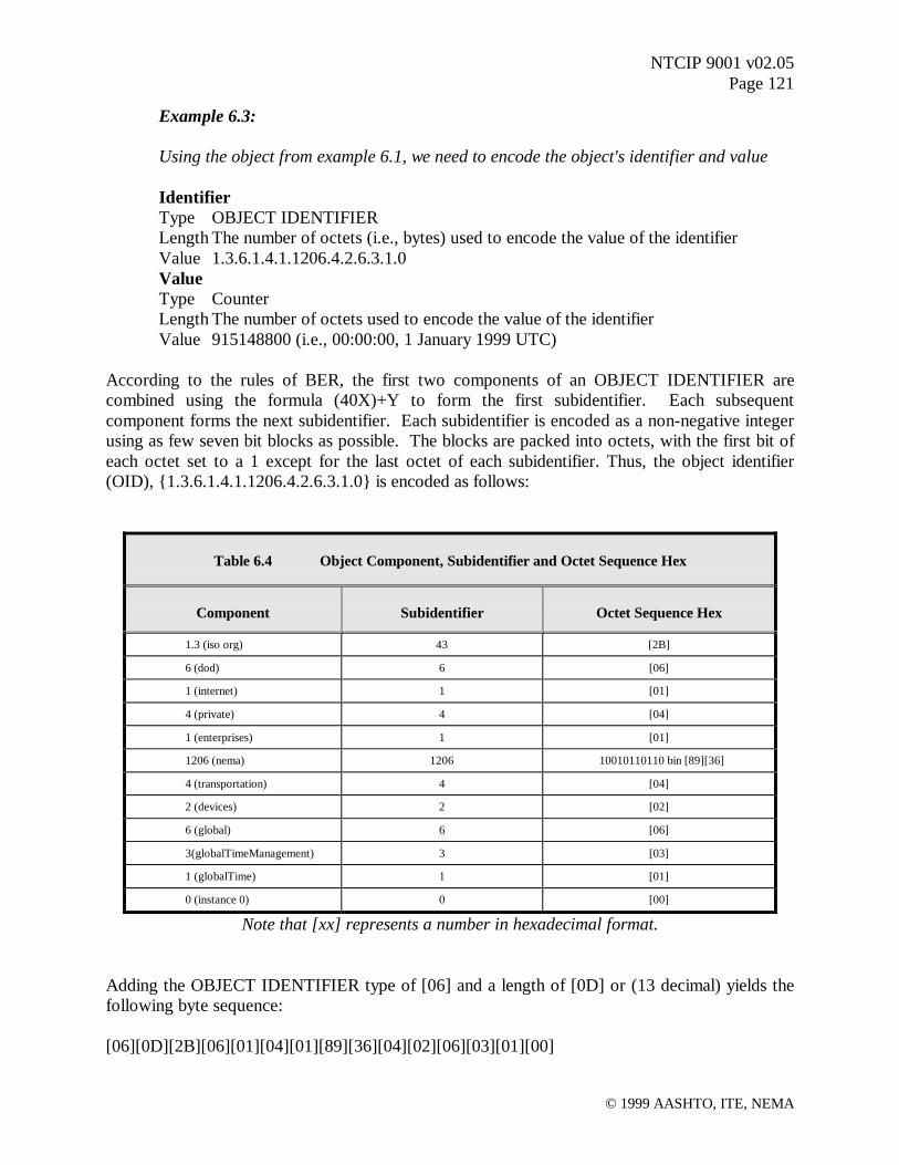
NTCIP 9001 v02.05Page 121
© 1999 AASHTO, ITE, NEMA
Example 6.3:
Using the object from example 6.1, we need to encode the object's identifier and value
IdentifierType OBJECT IDENTIFIERLength The number of octets (i.e., bytes) used to encode the value of the identifierValue 1.3.6.1.4.1.1206.4.2.6.3.1.0ValueType CounterLength The number of octets used to encode the value of the identifierValue 915148800 (i.e., 00:00:00, 1 January 1999 UTC)
According to the rules of BER, the first two components of an OBJECT IDENTIFIER arecombined using the formula (40X)+Y to form the first subidentifier. Each subsequentcomponent forms the next subidentifier. Each subidentifier is encoded as a non-negative integerusing as few seven bit blocks as possible. The blocks are packed into octets, with the first bit ofeach octet set to a 1 except for the last octet of each subidentifier. Thus, the object identifier(OID), {1.3.6.1.4.1.1206.4.2.6.3.1.0} is encoded as follows:
Table 6.4 Object Component, Subidentifier and Octet Sequence Hex
Component Subidentifier Octet Sequence Hex
1.3 (iso org) 43 [2B]
6 (dod) 6 [06]
1 (internet) 1 [01]
4 (private) 4 [04]
1 (enterprises) 1 [01]
1206 (nema) 1206 10010110110 bin [89][36]
4 (transportation) 4 [04]
2 (devices) 2 [02]
6 (global) 6 [06]
3(globalTimeManagement) 3 [03]
1 (globalTime) 1 [01]
0 (instance 0) 0 [00]
Note that [xx] represents a number in hexadecimal format.
Adding the OBJECT IDENTIFIER type of [06] and a length of [0D] or (13 decimal) yields thefollowing byte sequence:
[06][0D][2B][06][01][04][01][89][36][04][02][06][03][01][00]

NTCIP 9001 v02.05Page 122
© 1999 AASHTO, ITE, NEMA
Next, we encode the data value, which is 915148800. BER encodes Counters in the same way asit encodes INTEGERs, with a two’s complement representation using the minimum number ofoctets (note - this means the value 255 would be encoded in two bytes, [00][FF], so that the highorder bit is set to zero indicating a positive number). Thus, the byte sequence of would be:
[36][8C][10][00]
A Counter has a type code of [41].
Thus, our object value with a type of [41] and a length of [04] would become:
[41][04][36][8C][10][00]
The combined byte SEQUENCE (Type [30]) for the OID and value has a length of 21 ([15]).Thus, the entire encoding for this object is:
[30][15][06][0D][2B][06][01][04][01][89][36][04][02][06][03][01][00][41][04][36][8C][10][00]
If STMP was used, a dynamic object could be configured to include this object. In this case,only the object identifier would not be transmitted (because each end of the link would alreadybe aware of what data to expect next). Further, the data value would be encoded using OctetEncoding Rules (OER), which is more efficient than BER. Thus, an STMP dynamic objectwould encode the above information in 4 bytes instead of the 23 bytes shown (i.e., 21 plus typeand length of the sequence). However, STMP only supports thirteen dynamic objects; thus, thisbenefit is not achieved on every exchange.
Example 6.3 examined only two data types that can be encoded with BER. BER containsencoding rules for all ASN.1 types.
6.4.2.2 Encoding the SNMP Data Packet
We have created an object using ASN.1, placed it in a tree structure, gave it a real value, andfinally encoded the object and its value using BER. Now this information must be given in acontext. For example, is this a request to set the time, or is it a response to a get request? Thecontext is given by the surrounding structure of the data packet, as defined by the rules ofSNMP.
SNMP uses a get/set/trap paradigm. The table below lists the SNMP message types, purposesand originators.

NTCIP 9001 v02.05Page 123
© 1999 AASHTO, ITE, NEMA
Table 6.5 SNMP Message Type, Purpose, and Originator
Message Type Purpose Originator
Get Request Contains a list of objects, the agent is to return the values Management Application
Get Next Request Contains a list of objects, the agent is to return the values of the nextsequential object from those indicated. Management Application
Set Request Contains a list of objects and values, the agent is to set the values in itsMIB per this message Management Application
'Get' Response Agent response to either a Get or a Set request Agent Application
Trap An Agent initiated transmission to indicate that a defined event hasoccurred. Agent Application
The SNMP Message structure is given by the following ASN.1 structure:
Message ::= SEQUENCE {version INTEGER { version-1(0) },community OCTET STRING,data CHOICE {
get-request GetRequest-PDU,get-next-request GetNextRequest-PDU,get-response GetResponse-PDU,set-request SetRequest-PDU,trap Trap-PDU}
}All of the PDU structures have essentially the same structure, as follows, with a different Tag.
GetRequest-PDU ::= [0] IMPLICIT SEQUENCE {request-id RequestID,error-status ErrorStatus,error-index ErrorIndex,variable-bindings SEQUENCE OF SEQUENCE {
name OBJECT IDENTIFIER,value ObjectSyntax -- i.e., the SYNTAX of the selected object}
}
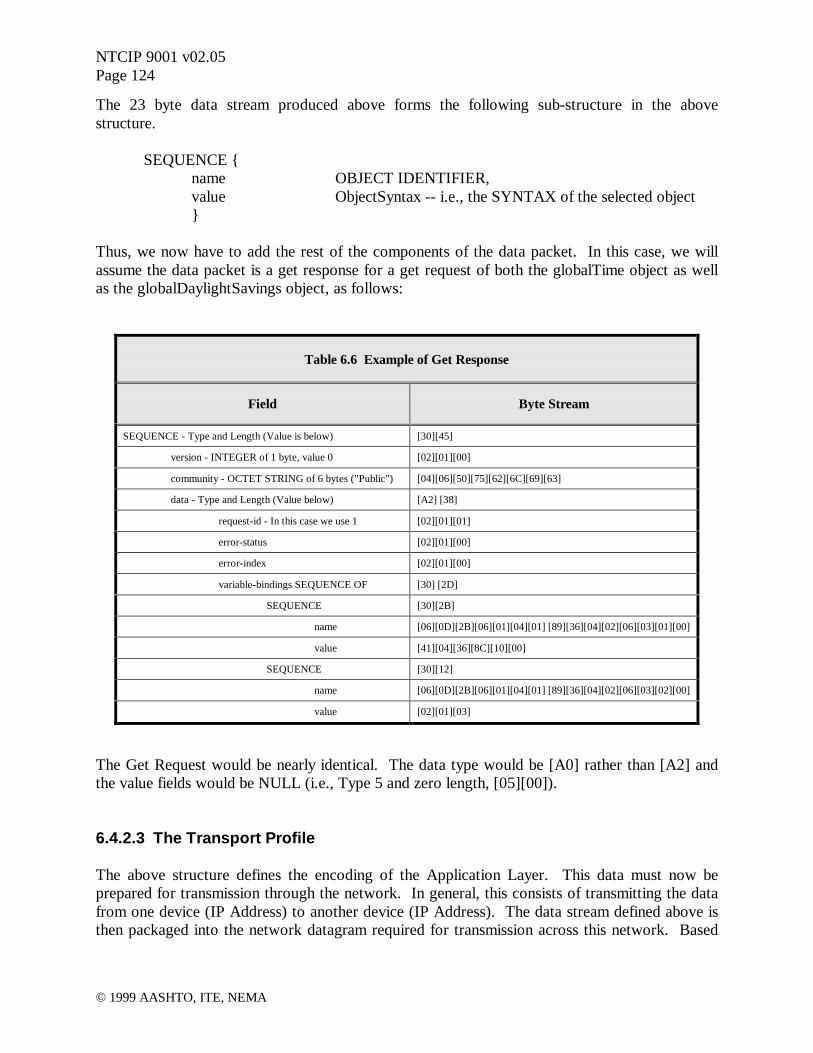
NTCIP 9001 v02.05Page 124
© 1999 AASHTO, ITE, NEMA
The 23 byte data stream produced above forms the following sub-structure in the abovestructure.
SEQUENCE {name OBJECT IDENTIFIER,value ObjectSyntax -- i.e., the SYNTAX of the selected object}
Thus, we now have to add the rest of the components of the data packet. In this case, we willassume the data packet is a get response for a get request of both the globalTime object as wellas the globalDaylightSavings object, as follows:
Table 6.6 Example of Get Response
Field Byte Stream
SEQUENCE - Type and Length (Value is below) [30][45]
version - INTEGER of 1 byte, value 0 [02][01][00]
community - OCTET STRING of 6 bytes ("Public") [04][06][50][75][62][6C][69][63]
data - Type and Length (Value below) [A2] [38]
request-id - In this case we use 1 [02][01][01]
error-status [02][01][00]
error-index [02][01][00]
variable-bindings SEQUENCE OF [30] [2D]
SEQUENCE [30][2B]
name [06][0D][2B][06][01][04][01] [89][36][04][02][06][03][01][00]
value [41][04][36][8C][10][00]
SEQUENCE [30][12]
name [06][0D][2B][06][01][04][01] [89][36][04][02][06][03][02][00]
value [02][01][03]
The Get Request would be nearly identical. The data type would be [A0] rather than [A2] andthe value fields would be NULL (i.e., Type 5 and zero length, [05][00]).
6.4.2.3 The Transport Profile
The above structure defines the encoding of the Application Layer. This data must now beprepared for transmission through the network. In general, this consists of transmitting the datafrom one device (IP Address) to another device (IP Address). The data stream defined above isthen packaged into the network datagram required for transmission across this network. Based

NTCIP 9001 v02.05Page 125
© 1999 AASHTO, ITE, NEMA
on the decision to use the Internet Transport Profile, this will entail placing the above data streaminto an UDP datagram and then placing the UDP datagram into an IP packet.
6.4.2.4 The Subnetwork Profile
Once the IP packet is ready for transmission, it must be prepared for transmission across the nextlink (i.e., the subnetwork). Based on the decision to use the PPP Subnetwork Profile, this entailsencapsulating the IP packet into a PPP frame and ensuring that the PPP session is properlyestablished before the frame is transmitted. Likewise, at some point after transmission, the linkshould be closed.
6.5 Defining New Objects
AASHTO, ITE and NEMA have defined an open and expandable protocol. NTCIP permitscompletely open database definitions without precluding completely proprietary (closed) ones.NTCIP will serve both open and closed databases on the same network. Users are encouraged toreview the existing MIB object definitions before attempting to add new ones.
The creation of a new MIB module can be quite easy. This is especially true if the device to besupported already has a list of defined requirements and database. Start by rewriting the existingdatabase using ASN.1. Next, define the necessary objects for the device and attempt to organizethem in a subtree. Obtain from NEMA, a root node for the subtree under the NEMA private orexperimental node. Seek comments from NEMA, manufacturers, and users of similar devices.In the early stages of NTCIP development, it may be sufficient to list the needed objects by nameand proposed data types (submit them to the Joint NTCIP Standards Committee for furtherdevelopment). Above all, try to use the existing object definitions as much as possible; this willfurther compatibility between devices.
6.6 Examples of Implementation Problems
A number of issues arose during the integration of the various components of the NTCIPdemonstration, which was unveiled at TRB in January 1996. These issues are documented hereto provide future implementers and integrators information for their design consideration.
6.6.1 Protocol-Related Issues
Implementing a standard requires careful examination of a large amount of text within thestandards. A number of the problems discovered during the integration work related to invalidinterpretation of the specifications, especially relating to those clauses that reference otherspecifications without providing significant detail. In order to minimize the number of theseconflicts in the future, a discussion of some of these issues is provided below.

NTCIP 9001 v02.05Page 126
© 1999 AASHTO, ITE, NEMA
6.6.1.1 Bit and Byte Order
Bit and byte order in a computer are not necessarily the same as the bit and byte order on thetransmission medium. The transmission order varies in accordance with the guidelines ofinternational standards. Implementations should ensure that the representation of the most andleast significant bits and bytes in the computer accurately reflect what is sent and received on thetransmission media.
6.6.1.2 Extended Addresses
There has been some confusion about how large of a high-level data link control (HDLC)address must be supported. For both of the PMPP and PPP Subnetwork Profiles, NTCIP devicesare required to fully support one-byte addresses and to accept incoming frames with two-byteaddresses to the device address. Production of frames with two-byte addresses is optional as issupport for configuring the device to an address greater than 63.
All addresses are odd; if the first byte of an address is even, then the address is multibyte.
6.6.1.3 Maximum Duration Between Successive Bytes
Many existing field devices use proprietary protocols that expect incoming messages to be aseries of bytes with minimal delay between the bytes. They will time out as an end of messagewhen a byte is not received in 15 ms for 1,200-bps communications. This means thatconsecutive messages must be separated by about 30 ms at 1,200 bps. With the simultaneous useof soft carrier turnoff this gap must be increased by the soft carrier turnoff time. At highertransmission rates these times are proportionally reduced.
Because of the desire for full-duplex communications, devices conforming to the PMPP Profileshould be designed to support much greater durations between successive bytes as suggested inthe NTCIP documents. In short, the only distinguishing limit of a message is the 0x7E flag.
6.6.1.4 Response Time
The public domain code that is available was developed using DOS and Windows; in both casesthe serial port interrupt is only checked every 50 ms. Thus, these systems do not perform quiteas well as desired; however, this was not an issue for the demonstration.
A real product should use a serial port driver to achieve the desired performance. The desiredperformance is system dependent and is stored in the T2 [the maximum time that a device isallowed to take before starting to send a response] object. In a multi-drop environment it isdesirable to minimize the duration of the T2 timer. A T2 value of 20 ms or less is desirable, but
NTCIP 9001 v02.05Page 127
© 1999 AASHTO, ITE, NEMA
not always achievable. According to NTCIP standards, the secondary is not allowed to respondafter its T2 timer expires.
6.6.1.5 Control Byte
PMPP includes support for three control byte values. A primary can transmit an unnumberedpoll (0x33), an unnumbered information command with the poll bit set (0x13), or an unnumberedinformation command without the poll bit set (0x03). The secondary must respond to everyframe received with the poll bit set (i.e., either 0x33 or 0x13); the response frame must be anunnumbered information response with the final bit set (0x13). The secondary may not transmitat any other time. (Note that these values are presented according to Internet encoding rules.)
PPP devices are peer devices (i.e., either the management station or the field device maycommunicate at any time because they are the only devices on the 4-wire link). In thisenvironment, there is no need to give permission to the other device, nor is there a need to forcea data link response. As such, the PPP Profile only uses the unnumbered information commandwithout the poll bit set for both ends of the link. This byte may be omitted, if such operation haspreviously been negotiated (see the PPP Subnetwork Profile and the PPP RFC).
6.6.1.6 Frame Handling
In PMPP systems, the primary may constantly poll each device in order to determine whether ithas any information to report. If the primary station has information to transmit with this poll(e.g., a request), it encapsulates this data in an unnumbered information command with the pollbit set. If there is not any information to send, it sends an “empty” frame of six bytes called anunnumbered poll frame. If the primary station has information to send, but does not want to givethe opportunity for the receiving device to respond (e.g., a broadcast), it sends the data in anunnumbered information frame without the poll bit set.
When a secondary station receives an unnumbered information frame with the poll bit set or anunnumbered poll, it responds with an unnumbered information frame with the final bit set. If thesecondary has any data to send with this frame, it is encapsulated within the frame. If thesecondary does not have any data to send, it should send an empty frame.
When a secondary station receives an information command without the poll bit set (e.g. abroadcast message), it does not respond.
It should be further noted that these rules only deal with the data link layer. For example, acentral system may send a broadcast message without a poll at the data link layer, whilerequesting a response at the application layer. The remote device would prepare a response atthe application layer that would then be stored in the device’s data link layer. This responsecould only be sent out after the device has received a frame with the poll bit set.

NTCIP 9001 v02.05Page 128
© 1999 AASHTO, ITE, NEMA
For example, if dynamic object 1 had been defined to be the time object, central could send thefollowing byte stream:
Flag Addr Ctrl IPI STMP ----SET Time---- CRC Flag7E FF 03 C1 91 31 E6 E7 00 XX XX 7E
The address indicates that it is received by everyone and the control byte prevents anyone fromresponding on the wire; however, the STMP byte is a SET with response. Thus, all of thedevices generate responses at the application layer and they are sent to the data link layer to betransmitted. Then, the data link layer waits until permission is granted for the device to speak(e.g., an unnumbered poll frame). In this way, a central system can broadcast the time and thengo back and ensure that all the devices received the message.
If the secondary has a pending response waiting at the data link layer, it should send the responseimmediately upon receiving a frame with the poll bit set. If the incoming frame containsinformation, the information should be processed. This might entail producing a new responsethat will be sent to the data link layer, where it will reside until the next poll is received.
A device is responsible for storing one response frame at the data link layer. If a secondresponse is generated before the first is sent, the first response should be overwritten.
6.6.1.7 CRC Algorithm
Examples of how to code the cyclical redundancy check (CRC) algorithm can be found in theAB3418 code and the FHWA code used the demonstration. This same algorithm is used in bothPMPP and PPP.
6.6.1.8 Invalid Frame
In both PMPP and PPP, when a device receives an invalid frame it should just discard the frame.Invalid frames include those with invalid CRCs, invalid initial protocol identifiers, etc. Devicesshould not provide any response to invalid frames.
6.6.1.9 STMP Message Type Byte
To see how the STMP Message Type Byte is coded and used, see NEMA Standards PublicationTS 3.2, National Transportation Communications for ITS Protocol, Simple TransportationManagement Framework, page 5-1.
NTCIP 9001 v02.05Page 129
© 1999 AASHTO, ITE, NEMA
6.6.1.10 Length Values for Variable Message Fields
The exact meaning of this field (i.e., which bytes are included in the count) has led to someconfusion. The count value does not include the count byte in the count (i.e., the count starts thebyte after the count byte).
6.6.2 Systems Integration Issues
In addition to those issues raised about the interpretation of the specifications, there were alsoissues over how systems should be designed and what should be required in procurementspecifications to achieve the goal of systems interoperability. This section provides someguidance on how to approach these issues.
6.6.2.1 Carriers
It is very important that secondary stations on multidrop lines turn off their modem carriers whennot sending data. After responding to a poll, the carrier must be removed from the line so thatother stations may respond.
6.6.2.2 Number of Devices on a Channel
The input impedance of the transmission output circuit in the field device modems limits themaximum number of field devices that can reliably be supported on a single modem channel.Each of these outputs is a load on the field device transmission line. A practical upper limit issomewhere around 15 field devices for the current technology 202 modems. Advanced 202modems can be used that will isolate the individual transmission circuits unless the modem isactively transmitting. In a system with only four to seven field devices per channel thisconsideration can usually be neglected, since communications timing is usually the determiningfactor in the maximum number of devices per channel. Section 5 provides a more detailedexplanation for determining the maximum number of devices per channel.
6.6.2.3 MIB Issues
All NTCIP procurements should specify that the manufacturers/developers must provide thedevices' MIB module(s) to the purchasing agency, with rights to distribute to their agents (e.g.,those persons acting on behalf of the agency). The MIBs should be provided in ASCII format onthe medium of the procuring agency's choice. The MIBs should include all Simple NetworkManagement Protocol (SNMP)/Simple Transportation Management Protocol (STMP) objectsthat the device(s) support.

NTCIP 9001 v02.05Page 130
© 1999 AASHTO, ITE, NEMA
6.7 Development Resources
There are a wide variety of resources available that relate to the NTCIP. This section lists someof the resource materials that have been used in the development process and earlyimplementations, as well as the location of developed materials.
6.7.1 Web Sites
A wide range of documentation is available on the World Wide Web NTCIP Home Page locatedat: http://www.ntcip.org
The site currently includes such items as these:• NTCIP Profile documents• NTCIP object definitions for a variety of devices• Various white papers written during the development of the initial standards• FHWA-sponsored software packages (e.g., NTCIP demonstration and NTCIP Exerciser).
Other web sites of interest are shown in the following table.
Table 6.7 NTCIP Related Web Sites
Web Site Address Description
NTCIP http://www.ntcip.org/ The official web site for NTCIP and related documents andinformation.
DATEX-ASN http://www.viggen.com/ntcip/datex/index.htm The web site for DATEX-ASN documents and information
DATEX-Net http://www.datex.org/ The official web site of the DATEX-Net Standard currently inuse in Europe.
IANA http://www.iana.org/numbers.html The Internet Assigned Numbers Authority web site.
IEEE ITS Page http://stdsbbs.ieee.org/groups/scc32/index.html Links to all of the IEEE standards efforts, including ATIS,Incident Management, Data Dictionaries, and Data Registries.
ISO http://www.iso.ch/ The official ISO home page.
ISO TC204 http://www.sae.org/TECHCMTE/204.htm The home page for ISO Technical Committee 204 (i.e., thecommittee for ITS standards).
ITE http://www.ite.org/ ITE web site.
ITS America http://www.itsa.org/ The home page for ITS America.
NEMA Standards http://www.nema.org/nema/standards/ Site for ordering NTCIP standards.

NTCIP 9001 v02.05Page 131
© 1999 AASHTO, ITE, NEMA
Table 6.7 NTCIP Related Web Sites
Web Site Address Description
RFC Index http://www.nexor.com/public/rfc/index/rfc.html A search engine for all of the Internet RFCs.
TCIP http://www.tcip.org The home page for the Transit Communications InterfaceProfiles.
6.7.2 Sources of Public Domain Software
There are two basic prototype implementations of NTCIP software. Neither of these packageswere designed to operate a real system; rather, they were designed to provide tools to theindustry to test equipment submitted as being compliant to a specific protocol. Unfortunately,there is no ongoing program to maintain these packages.
6.7.2.1 NTCIP Exerciser
This NTCIP Exerciser is able to read in any properly formatted management information base(MIB) from a floppy disk and support the exchange of fully compliant NTCIP messages underthe direction of the operator. The package supports the creation of simple macros to enable theuser to perform a number of operations sequentially and to record the results. The currentversion supports the simulation of either a management station (funded by the FHWA) or anagent (funded by Virginia DOT). It currently supports the STMF Application Profile (SNMPonly, the STMF portion is out of date), Null Transport Profile, and both the PMPP-232Subnetwork Profile and the PPP Subnetwork Profile. The most recent version of this software isavailable for free on the NTCIP Web Site. It is designed for Windows NT.
6.7.2.2 Field Device Simulator
The FHWA also developed a DOS based program to emulate a field device that supports theobjects contained in the Global Object Definitions. This program supports the STMFApplication Profile (SNMP-only, the STMF code is out of date), the Null Transport Profile, andthe PMPP-232 Subnetwork Profile.
6.7.3 Books
During the development of the standards and prototypes, a number of books were consulted;including the following:

NTCIP 9001 v02.05Page 132
© 1999 AASHTO, ITE, NEMA
• Stevens, W. R., TCP/IP Illustrated, Volume 1, The Protocols: Reading, Massachusetts:Addison Wesley Publishing Co. 1994
• Wright, G. R. and Stevens, W. R., TCP/IP Illustrated, Volume 2, The Implementation,Reading, Massachusetts: Addison Wesley Publishing Co. 1995
• International Technical Support Center Raleigh N. C., TCP/IP Tutorial and TechnicalOverview, Document Number GG24-3376-01, IBM Corp, Armonk, N.Y.: June 5, 1990,2nd Edition
• Rose, M. T., The Open Book, Englewood Cliffs, N.J.: Prentice Hall, 1990• Stallings, W., SNMP, SNMPv2, and CMIP The Practical Guide to Network Management
Standards, Reading, Massachusetts: Addison Wesley Publishing Co. 1993• Perkins, D. and McGinnis, E., Understanding SNMP MIBS, 1997, Upper Saddle River,
New Jersey: Prentice Hall, Inc., 1997.
6.7.4 Other Resources
In addition, there are articles in the December 1995, January 1996, and April 1996 issues of theITE Journal. There are periodic releases of NTCIPNews, a newsletter produced by the NTCIPJoint Committee. Finally, there are updates of ITS standards in each Journal.
6.8 Summary
Transportation devices, like any other computer device, require databases, processors, andinterfaces. If the device intends to share its data with other devices, a communication protocol isrequired. NTCIP fulfills the requirement for a set of communication protocols that are flexibleenough to support the variety of fixed-point communications systems within ITS.

NTCIP 9001 v02.05Page 133
© 1999 AASHTO, ITE, NEMA
7 GLOSSARY
7.1 Acronyms
Table 7.1 Glossary
Acronym/Abbreviation Definition
AASHTO American Association of State Highway and Transportation Officials
ASC Actuated Signal Controller
ASN.1 Abstract Syntax Notation One
ATIS Advanced Traveler Information System
ATMS Advanced Traffic Management System
BER Basic Encoding Rules
bps bits per second
C2C Center to Center
C2F Center to Field
CCTV closed-circuit television
CORBA Common Object Request Broker Architecture
CRC Cyclical Redundancy Check
DATEX Data Exchange Between Systems
DMS Dynamic Message Sign
ESS Environmental Sensor Systems
FCS Frame Check Sequence (see Cyclic Redundancy Check)
FHWA Federal Highway Administration
FSK Frequency Shift Keying
FTP File Transfer Protocol
HAR Highway Advisory Radio
HDLC High-Level Data Link Control
IANA Internet Assigned Numbers Authority
IEEE Institute of Electrical and Electronic Engineers
IP Internet Protocol
IPI Initial Protocol Identifier
ISO International Organization for Standardization
ITE Institute of Transportation Engineers
ITS Intelligent Transportation Systems
MIB Management Information Base

NTCIP 9001 v02.05Page 134
© 1999 AASHTO, ITE, NEMA
Table 7.1 Glossary
Acronym/Abbreviation Definition
NEMA National Electrical Manufacturers Association
NTCIP National Transportation Communication for ITS Protocol
OER Octet Encoding Rules
OSI Open Systems Interconnection
PDU Protocol Data Unit
PER Packed Encoding Rules
PICS Protocol Implementation Conformance Statement
PMPP Point-to-Multi Point Protocol
PPP Point-to-Point Protocol
RFC Request For Comment
SLIP Serial Line Internet Protocol
SNMP Simple Network Management Protocol
SNMPv2 Simple Network Management Protocol version 2
STMF Simple Transportation Management Framework
STMP Simple Transportation Management Protocol
TCIP Transit Communications Interface Protocol
TCP Transmission Control Protocol
TCP/IP Transmission Control Protocol/Internet Protocol
TEA-21 Transportation Equity Act for the 21st Century
TFTP Trivial File Transfer Protocol
TMC Transportation Management Center
TMIB Transportation MIB
TMS Transportation Management Systems
TOC Transportation Operation Center
UDP User Datagram Protocol
UDP/IP User Datagram Protocol/Internet Protocol
VMS Variable Message Sign

NTCIP 9001 v02.05Page 135
© 1999 AASHTO, ITE, NEMA
7.2 Definitions
Table 7.2 Definitions
Term/AbbreviationAcronym Definition
agent An STMF entity that receives commands and transmits responses to the received commands.
ANSI American National Standards Institute, a standardization group that develops or adopts standards for theUnited States.
application services The services collectively offered by the upper four layers of the OSI model.Applications ProgrammerInterface (API) A set of calling conventions defining how a service is invoked through a software package.
ASCII American Standard Code for Information Interchange. A 7-bit binary code representation of letters, numbers,and special characters. It is universally supported in computer data transfer.
ASN.1 Abstract Syntax Notation One, a formal language for describing information to be processed by computer, anISO standard.
asynchronous Data transmission in which the actual data is preceded by a start bit and followed by a stop bit since the timebetween transmitted characters varies. Compare with Synchronous.
authentication The process whereby a message is associated with a particular originating entity.authorization The process whereby an access policy determines whether an entity is allowed to perform an operation.
bandwidthThe range of frequencies that can be used for transmitting information on a channel, equal to the differencein Hertz (Hz) between the highest and lowest frequencies available on that channel. Indicates thetransmission-carrying capacity of a channel.
Basic Encoding Rules (BER) A series of procedures for describing transfer syntax of types specified with ASN.1. Transfer syntax is theactual representation of octets to be sent from one network entity to another.
Baud RateThe number of discrete signal events per second occurring on a communications channel. It is ofteninterchanged with bits per second (bps), which is technically inaccurate but widely accepted for slower bitrates.
bit Binary digit. A single basic computer signal consisting of a value of 0 or 1, off or on.
Bit error rate (BER) The number of bits transmitted incorrectly. In digital applications it is the ratio of bits received in error tobits sent.
bps Bits per second, transmission rate (speed) of databridge A means for connecting two networks at the data link layer.broadcast address An address referring to all stations on a medium.
byte A group of bits acted upon as a group, which may have a readable ASCII value as a letter or number or someother coded meaning to the computer. it is commonly used to refer to 8-bit groups.
(AB3418) California AssemblyBill No. 3418
A bill that requires all new or upgraded traffic signal controllers installed in California after January 1, 1996,to incorporate a standard communications protocol. Caltrans has published this specification for developers.
carrierA continuous frequency capable of being either modulated or impressed with another information-carryingsignal. Carriers are generated and maintained by modems via the transmission lines of the telephonecompanies.
checksum An arithmetic sum used to verify data integrity.
Cyclical Redundancy CheckCyclical Redundancy Check. An error-detection technique consisting of a cyclic algorithm performed oneach “block” of data at the sending and receiving end of the transmission. As each block is received, theCRC value is checked against the CRC value sent along with the block.
data Information before it is interpreted.
data dictionaryAn organized listing of all data elements that are essential to the system, with precise, definitions so that boththe user and the system developer will have a common understanding of input, output, components ofstorage, and intermediate calculations.
data flow The description of information movement and the transforms that are applied as the data moves from input tooutput.
Data Link Layer Layer 2 of the OSI Reference Model; it is responsible for transmission, framing, and error control over asingle communications link.
datagram A self-contained unit of data transmitted independently of other datagrams.

NTCIP 9001 v02.05Page 136
© 1999 AASHTO, ITE, NEMA
Table 7.2 Definitions
Term/AbbreviationAcronym Definition
DTE Data Terminal Equipment. The device that is the originator or destination of the data sent by a modem. (AnEIA/TIA – 232 – E signal)
DTR Data Terminal Ready. A signal generated by most modems indicating a connection between the DTE(computer) and the modem. When DTR is high, the computer is connected. (An EIA/TIA – 232 – E signal)
EIA/TIA-232-E Electronic Industries Association/Telecommunications Industries Association specification that defines theserial port on a PC.
end-to-end services The services collectively offered by the lower three layers of the OSI model.
flow control
A mechanism that compensates for differences in the flow of data to and output from a modem or computer.Either hardware or software can be used for this control to prevent data loss. Hardware flow control usingthe modem makes use of a buffer to store data to be sent and data received. Flow control is necessary if thecommunications port is locked at a higher rate than the connection rate.
FSK modem interface Typical method of traffic control system communications, phone line, or twisted wire based.
full duplex Signal flow in both directions at the same time. It is sometimes used to refer to the suppression of on-linelocal echo and allowing the remote system to provide a remote echo.
gateway A router and translater between protocols; also, (imprecise usage) an entity responsible for complex topologymappings.
half duplex Signal flow in both directions, but only one way at a time. It is sometimes used to refer to activation of localecho which causes a copy of sent data to be displayed on the sending display.
HDLC Generalized network approach: high-level data link control
Highway Advisory Radio (HAR) Low-powered AM or FM stations that broadcast brief messages to standard car radios from smalltransmitters placed near highways.
host (Internet usage) an endsystem.IETF lnternet Engineering Task Force, a group chartered by the IAB to develop certain RFCs for standardization .indirect routing The process of sending a network message to a router for forwarding.
infrastructure This refers to all fixed components to a transportation system such as rights of way, tracks, equipment,stations, parking/park-n-ride lots, signalization equipment, maintenance facilities.
Intelligent TransportationSystems (ITS)
A major national initiative to improve information, communication, and control technologies in order toimprove the efficiency of surface transportation. Technological innovations that apply directcommunications and information processing to improve the efficiency and safety of surface transportationsystems. These include on-board navigation for vehicles, emergency communications systems, electronictoll/fare collections, traffic management centers, etc.
intermediate system A network device performing functions from the lower three layers of the OSI model. Intermediate systemsare commonly thought of as routing data for end systems.
Intermodal SurfaceTransportation Efficiency Act of1991 (ISTEA)
Federal authorizing legislation for highways, transit, and other surface transportation programs. Establishedintermodal objectives for national transportation system to achieve efficiency, air quality, and environmentalquality.
intermodalism The use and coordination of more than one mode of transportation.International Organization forStandardization (ISO)
An international standards organization. ANSI is the primary interface to ISO within the United States. Oftenthought to be International Standards Organization because of the usage ISO for short.
InternetA large collection of connected networks, primarily in the United States, running the Internet suite ofprotocols. Sometimes referred to as the DARPA Intemet, NSF/DARPA, Intemet, or the Federal ResearchIntemet.
Internet Protocol (IP) The network protocol offering a connection less mode network service in the Internet suite of protocols.Internet suite of protocols A collection of computer-communication protocols originally developed under DARPA sponsorship.IP address A 32-bit quantity used to represent a point of attachment in an internet. An Internet Protocol Address.
lAB Internet Activities Board, group in charge of authorizing RFCs for the purpose of standardizing Internetoperations.
IANA Internet Assigned Numbers Authority, group in charge of assigning Internet addresses.
Local Area Network (LAN) Any one of a number of technologies providing high speed, low-latency transfer and being limited ingeographic size.
Management Information Base(MIB)
A collection of objects defined using Abstract Syntax Notation One (ASN.1) that can be accessed via anetwork management protocol. (See Structure of Management Information.)
manager The entity that sends commands to entries and processes their responses.maximum transmission unit The largest amount of user data that can be sent in a single frame on a particular medium.network A collection of subnetworks connected by intermediate systems and populated by end systems.network identifier That portion of an IP address corresponding to a network in an internet.

NTCIP 9001 v02.05Page 137
© 1999 AASHTO, ITE, NEMA
Table 7.2 Definitions
Term/AbbreviationAcronym Definition
Network Layer That portion of an OSI system responsible for data transfer across the network, independent of both themedia comprising the underlying subnetworks and the topology of those subnetworks.
network managementThe technology used to manage a network. Usually referring to the management of networking specificdevices such as routers. In the context of the NTCIP, refers to all devices including end systems that arepresent on the network or inter network.
NTCIPNational Transportation Communication for ITS Protocol, communications protocol under development.The development effort is being spearheaded by FHWA, NEMA, and the NTCIP Joint StandardsCommittee.
NTCIP Home Page Site on the World Wide Web where one may obtain the latest NTCIP information. The address ishttp://www.ntcip.org
NTCIP Steering Group A public/private advisory group composed of ITS experts that guides the development of the NTCIP.object A representation of a data element that is managed.
object identifier A unique name (identifier) that is associated with each type of object in a MIB. This is a defined ASN.1type.
OBJECT-TYPE
The macro defined in RFC-1212 which is the format used to define SNMP objects. In STMF, the OBJECT-TYPE macro consists of five fields:Object NameSyntaxDescriptionAccessStatus.
Open Systems Interconnection(OSI)
An international effort to facilitate communications among computers of different manufacture andtechnology.
parity A simple error detection method used in both communications and computer memory checking to determinecharacter validity.
PER Packed Encoding Rules, a variation of BER developed for use on low bandwidth communications links,specified in NEMA TS-3.2.
physical address The address of a physical interface.Physical Layer That portion of an OSI system responsible for the electro-mechanical interface to the communications media.Point-to-Point Protocol (PPP) Transmission of data between two and only two stations on a point to point link.Point-to-Multi-Point Protocol(PMPP) Transmission of data between multiple stations or nodes (i.e., one primary and multiple secondaries).
port numberIdentifies an application-entry to a transport service in the Internet suite of protocols. The concept of portsare often present in OSI literature, however, ports are not Internet standard, but exists as local networkconventions only.
Presentation Layer That portion of an OSI system responsible for adding structure to the units of data that are exchanged.
primary A node on a link which controls the polling to and from secondary nodes on that link and controls thecommunications from the secondary nodes on that link.
profile The defined protocol at each of the seven OSI layers.
protocolA formal set of conventions governing the format and relative timing of message exchange between twocommunicating processes. A system of rules and procedures governing communications between twodevices.
Protocol Data Unit (PDU) A part of transmitted data that contains information used by the protocol at a particular layer in the OSIstack.
proxy agent A device which receives and responds to network management commands on behalf of another entity.RFC Request for Comments, the name given to correspondence and standards by the IAB.router A level 3 (network layer) relaysecondary A node on a link that is controlled by the primary node in terms of polling and communications.service primitive An artifact modeling how a service is requested or accepted by a userSession Layer That portion of an OSI system responsible for adding control mechanisms to the data exchange.Simple TransportationManagement Framework(STMF)
Simple Transportation Management Framework, describes the organization of the information withindevices and the methods of retrieving or modifying any informaiton within the device. STMF also explainshow to generate and utilize computer readable information organization descriptions.
Simple TransportationManagement Protocol (STMP)
Simple Transportation Management Protocol, a variation of SNMP developed by NEMA to address lowbandwidth communication links and real time device monitoring.
SMI Structure of Management Information, a definition of how to create management objects and a hierarchical(tree like) definition of nodes where management objects will be attached for unique identification.
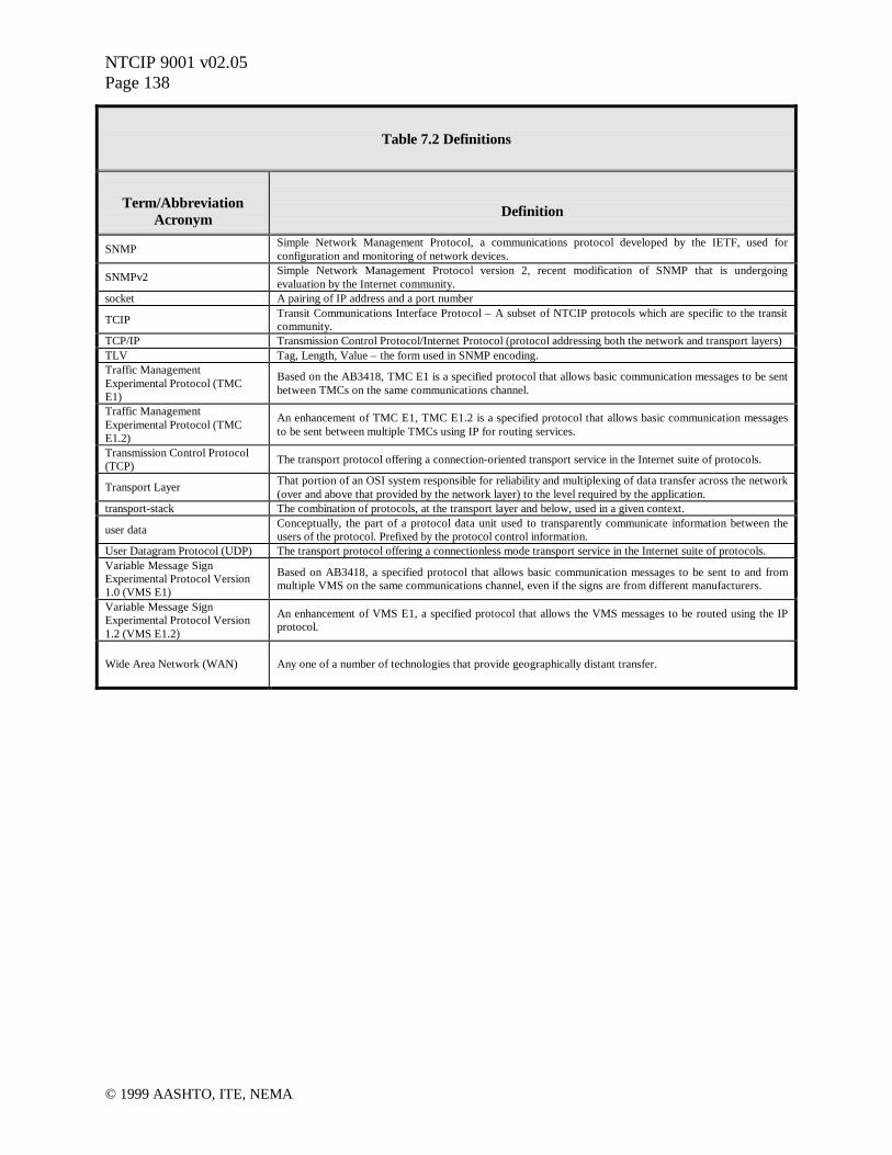
NTCIP 9001 v02.05Page 138
© 1999 AASHTO, ITE, NEMA
Table 7.2 Definitions
Term/AbbreviationAcronym Definition
SNMP Simple Network Management Protocol, a communications protocol developed by the IETF, used forconfiguration and monitoring of network devices.
SNMPv2 Simple Network Management Protocol version 2, recent modification of SNMP that is undergoingevaluation by the Internet community.
socket A pairing of IP address and a port number
TCIP Transit Communications Interface Protocol – A subset of NTCIP protocols which are specific to the transitcommunity.
TCP/IP Transmission Control Protocol/Internet Protocol (protocol addressing both the network and transport layers)TLV Tag, Length, Value – the form used in SNMP encoding.Traffic ManagementExperimental Protocol (TMCE1)
Based on the AB3418, TMC E1 is a specified protocol that allows basic communication messages to be sentbetween TMCs on the same communications channel.
Traffic ManagementExperimental Protocol (TMCE1.2)
An enhancement of TMC E1, TMC E1.2 is a specified protocol that allows basic communication messagesto be sent between multiple TMCs using IP for routing services.
Transmission Control Protocol(TCP) The transport protocol offering a connection-oriented transport service in the Internet suite of protocols.
Transport Layer That portion of an OSI system responsible for reliability and multiplexing of data transfer across the network(over and above that provided by the network layer) to the level required by the application.
transport-stack The combination of protocols, at the transport layer and below, used in a given context.
user data Conceptually, the part of a protocol data unit used to transparently communicate information between theusers of the protocol. Prefixed by the protocol control information.
User Datagram Protocol (UDP) The transport protocol offering a connectionless mode transport service in the Internet suite of protocols.Variable Message SignExperimental Protocol Version1.0 (VMS E1)
Based on AB3418, a specified protocol that allows basic communication messages to be sent to and frommultiple VMS on the same communications channel, even if the signs are from different manufacturers.
Variable Message SignExperimental Protocol Version1.2 (VMS E1.2)
An enhancement of VMS E1, a specified protocol that allows the VMS messages to be routed using the IPprotocol.
Wide Area Network (WAN) Any one of a number of technologies that provide geographically distant transfer.

NTCIP 9001 v02.05Page 139
© 1999 AASHTO, ITE, NEMA
8 BIBLIOGRAPHY
8.1 Selected Reading List
Table 8.1 Selected Reading List and References
Subject Reference
Object DefinitionUnderstanding SNMP MIBS, 1997, D. Perkins and E. McGinnis, Prentice Hall, Inc., ISBN 0-13-437708-7
ASN.1: The Tutorial & Reference, 1993, D. Steedman, Technology Appraisals Ltd., ISBN 1-871802-06-7
SNMP Protocol
SNMP, SNMPv2, and CMIP, 1993, W. Stallings, Addison-Wesley Publishing Company, Inc., ISBN 0-201-63331-0
SNMP, SNMPv2 and RMON, 1996, W. Stallings, Addision-Wesley Publishing Company, Inc., ISBN 0-201-63479-1
Managing Internetworks with SNMP, 1995, M. Miller, M&T Books, ISBN 1-5581-304-3
SNMP: A Guide To Network Management, 1995, S. Feit, McGraw Hill, Inc., ISBN 0-07-020359-8
TCP,UDP, IP and PPP Protocols
Internetworking with TCP/IP, 1995, D. Comer, Prentice Hall, Inc., ISBN 0-13-216987-8
TCP/IP: Architecture, Protocols, and Implementation, 1993, S. Feit, McGraw Hill, Inc., ISBN 0-07-020346-6
TCP/IP Illustrated, Volume 1, The Protocols, W. R. Stevens, 1994, Addison Wesley Publishing Co.
TCP/IP Isslustrated, Volume 2, The Implementation, G. R. Wright and W. R. Stevens, 1995, AddisonWesley Publishing Co.
TCP/IP Tutorial and Technical Overview, International Technical Support Center, Raleigh, NC, 1990,Document Number GC24-3376-01, IBM Corp.
Network InterfacesThe Ethernet Management Guide, 1995, M. Nemzow, McGraw-Hill, Inc., ISBN 0-07-046380-8
The Token-Ring Management Guide, 1995, M. Nemzow, McGraw-Hill, Inc, ISBN 0-07-046321-2
OSI Network Management Telecommunications Network Management into the 21st Century, 1994, S. Aidarous and T. Plevyak, IEEEPress, New York, NY
OSI Understanding OSI, 1994, J. Larmouth, http://www.salford.ac.uk/iti/books/osi.htm, 1997
CORBA
CORBA for Dummies, J. schettino, L. O’Hara, R S. Hohman, IDG Books, 1998
Instant CORBA, R. Orfali, D. Harkey, and J. Edwards, et al, John Wiley & Sons, 1997, ISBN 0471183334
CORBA Fundamentals & Programming, J. Siegel, Object Management Group, Inc., 1996
Object-Oriented Systems Design: An Integrated Approach, E. Yourdon, Yourdon Press Computing Systems(Prentice Hall), 1994, ISBN 0136363253
Object Lessons: Lessons in Object-Oriented Development Projects, SIGS Books, 1993, ISBN 0962747734
Profiles
Guide to Open System Specifications, European Workshop for Open Systems,http://www.ewos.be/goss/top.htm, 1997
US-DOD Internet Related Standardized Profiles, DISA Internet Librarian, http://www-library.itsi.disa.mil/org/mil_std.html, 1997
The Open Book, 1990, M. T. Rose, Prentice Hall

NTCIP 9001 v02.05Page 140
© 1999 AASHTO, ITE, NEMA
9 EXAMPLE NTICP IMPLEMENTATIONS
Several potential NTCIP Implementations are presented in this section as examples of how thevarious Information, Application, Transport, Subnetwork, and Plant Levels may be combined.
The following examples will occasionally make reference to legacy terminology such as ClassProfiles. Rather than developing a different Class Profile for each possible combination ofalternative selections at the various NTCIP Stack Levels, the NTCIP Joint Committee has chosento deprecate the use of alphanumeric class profile designations in lieu of individual standards ateach level. The user is now able to create an NTCIP Stack by selecting the appropriate standardsat each Level that is applicable for the application and system design. This approach enables theuser to better specify choices specific to the system being deployed.
9.1 Center-to-Field
Two examples are provided for center-to-field communications.
9.1.1 Example Center-to-Field Implementation Without Routing
Example 9.1 Example of a Center-to-Field Implementation Without Routing
This example shows one possible implementation of NTCIP center-to-fieldcommunications where routing through an intermediate device is not needed.
Figure 9.1 depicts a common example of a center-to-field NTCIP Implementation where routingthrough an intermediate device is not needed. In this example the Transport Level is NULbecause there is no need for a routing protocol.
The example NTCIP implementation illustrated in Figure 9.1 highlights one implementationsubset of the NTCIP Framework. The figure shows the standard(s) implemented at each NTCIPFramework Level. The example shows the implementation of both STMP and SNMP at theApplication Level and NULL at the Transport Level. Together, these standards provide servicesfor an NTCIP system, such as a traffic signal system, that does not involve routing throughintermediate devices. The example shows the selection of both STMP and SNMP at theApplication Level within the NTCIP Stack since this will be a common implementation manysystems, such as traffic signal systems, that use dynamic objects.
The implementation subset of the NTCIP Framework shown in this example is similar to thatonce known as the Class B Profile. It should be noted that the trend is moving away fromdenoting the various stacks with alphanumeric characters and is moving towards the designationof specific standards at each level within the NTCIP Framework. As a result, Class B should beregarded as a legacy term that will ultimately be abandoned in-lieu of an array of specific NTCIPFramework level standards.

NTCIP 9001 v02.05Page 141
© 1999 AASHTO, ITE, NEMA
The Subnetwork Level standard selected in this example is Point to Multi-Point, FSK modems.The Plant Level in this example NTCIP implementation is shown to be agency owned twistedpair wire, but any suitable media can be used.
9.1.2 Example Center-to-Field Implementation With Routing
Example 9.2 Example of a Center-to-Field Implementation With Routing
This example shows one possible implementation of NTCIP center-to-fieldcommunications where routing through one or more intermediate devices isneeded.
Figure 9.2 depicts a common example of a center-to-field NTCIP Implementation where routingthrough an intermediate device is needed. The routing can take either the form of connectionlessor connection-oriented transport delivery services depending on the selection at the TransportLevel. For connectionless transport delivery services, the selection of User Datagram Protocol
Center-to-Center
Plant LevelPlant Level
Figure 9.1 Example Center-to-Field Implementation
SLIP PPP PMPPFDDI Ethernet
Twisted Pair Telco Line Wireless
V Series Modem FSK Modem
Fiber Coax
UDPTCP
IP
NULL
DATEX TFTP SNMP STMPFTPCORBA
Transport Level
Subnetwork Level
Application Level
Information Level
Transport Level
Application Level
Information Level
Subnetwork Level
Dynamic Objects
ITS Data Model
Files
Data Objects
ATM
SONET
ITS Data Dictionary
ITS Message SetsReference Model
Center-to-Field
* Not all combinations between the Subnetwork and Plant Levels are feasible
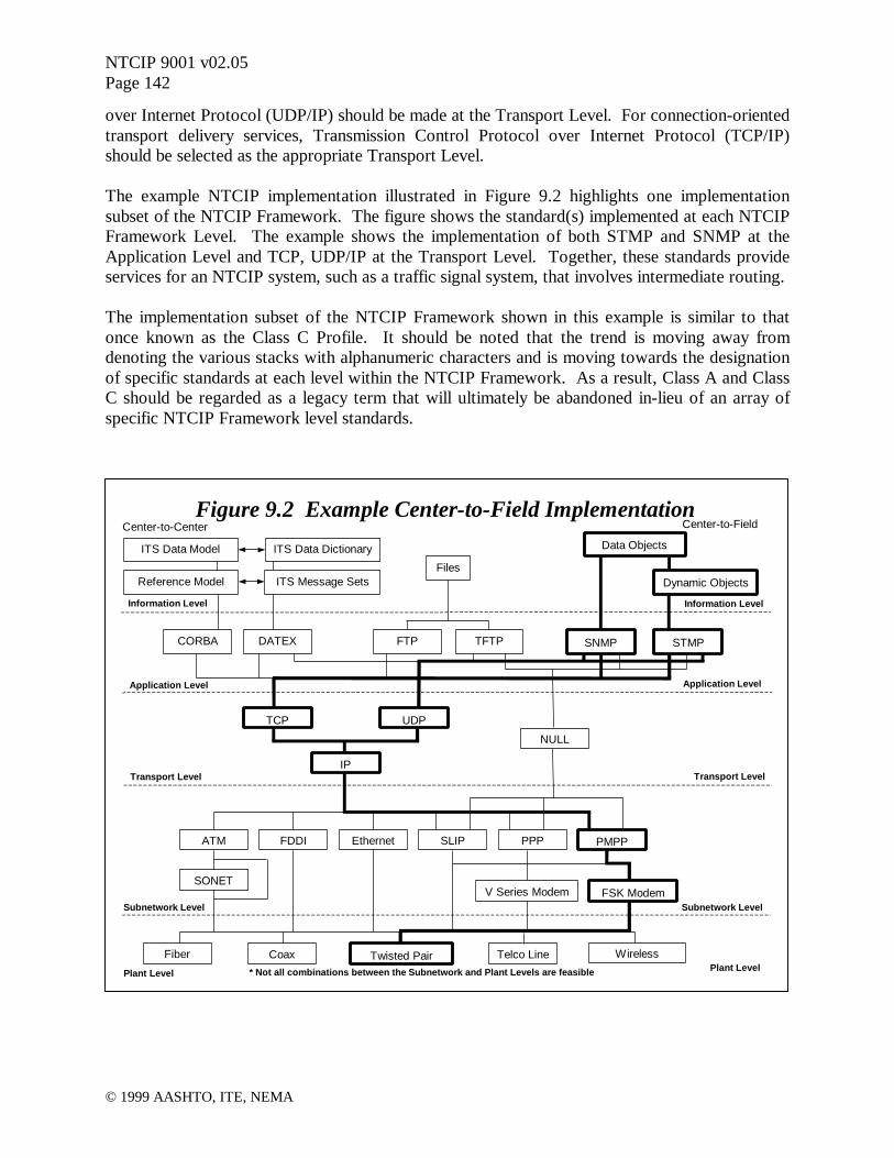
NTCIP 9001 v02.05Page 142
© 1999 AASHTO, ITE, NEMA
over Internet Protocol (UDP/IP) should be made at the Transport Level. For connection-orientedtransport delivery services, Transmission Control Protocol over Internet Protocol (TCP/IP)should be selected as the appropriate Transport Level.
The example NTCIP implementation illustrated in Figure 9.2 highlights one implementationsubset of the NTCIP Framework. The figure shows the standard(s) implemented at each NTCIPFramework Level. The example shows the implementation of both STMP and SNMP at theApplication Level and TCP, UDP/IP at the Transport Level. Together, these standards provideservices for an NTCIP system, such as a traffic signal system, that involves intermediate routing.
The implementation subset of the NTCIP Framework shown in this example is similar to thatonce known as the Class C Profile. It should be noted that the trend is moving away fromdenoting the various stacks with alphanumeric characters and is moving towards the designationof specific standards at each level within the NTCIP Framework. As a result, Class A and ClassC should be regarded as a legacy term that will ultimately be abandoned in-lieu of an array ofspecific NTCIP Framework level standards.
Center-to-Center
Plant LevelPlant Level
Figure 9.2 Example Center-to-Field Implementation
SLIP PPP PMPPFDDI Ethernet
Twisted Pair Telco Line Wireless
V Series Modem FSK Modem
Fiber Coax
UDPTCP
IP
NULL
DATEX TFTP SNMP STMPFTPCORBA
Transport Level
Subnetwork Level
Application Level
Information Level
Transport Level
Application Level
Information Level
Subnetwork Level
Dynamic Objects
ITS Data Model
Files
Data Objects
ATM
SONET
ITS Data Dictionary
ITS Message SetsReference Model
Center-to-Field
* Not all combinations between the Subnetwork and Plant Levels are feasible

NTCIP 9001 v02.05Page 143
© 1999 AASHTO, ITE, NEMA
The Subnetwork Level standard selected in this example is Point to Multi-Point, FSK modems.The Plant Level in this example NTCIP implementation is shown to be agency owned twistedpair wire, but any suitable media can be used.
9.2 Center-to-Center
Two examples are provided for center-to-field communications.
9.2.1 Example Center-to-Center Implementation using DATEX
Example 9.3 Example of a Center-to-Center Implementation using DATEX
This example shows one possible implementation of NTCIP center-to-centercommunications using DATEX.
Center-to-Center
Plant LevelPlant Level
Figure 9.3 Example Center-to-Field Implementation
SLIP PPP PMPPFDDI Ethernet
Twisted Pair Telco Line Wireless
V Series Modem FSK Modem
Fiber Coax
UDPTCP
IP
NULL
DATEX TFTP SNMP STMPFTPCORBA
Transport Level
Subnetwork Level
Application Level
Information Level
Transport Level
Application Level
Information Level
Subnetwork Level
Dynamic Objects
ITS Data Model
Files
Data Objects
ATM
SONET
ITS Data Dictionary
ITS Message SetsReference Model
Center-to-Field
* Not all combinations between the Subnetwork and Plant Levels are feasible

NTCIP 9001 v02.05Page 144
© 1999 AASHTO, ITE, NEMA
Figure 9.3 depicts an example center-to-center NTCIP implementation and is one variation of anapproach using DATEX. This NTCIP implementation example is intended for connection-oriented transport delivery services from a transportation management center to field devices.
The example NTCIP implementation illustrated in Figure 9.3 highlights one implementationsubset of the NTCIP Framework for center-to-center communications. The figure shows thestandard(s) implemented at each NTCIP Framework Level for using DATEX at the ApplicationLevel within the NTCIP Framework.
For center-to-center communications, the choices that are offered at the Application Levelinclude DATEX and CORBA. The choices that are defined for the Transport Level are the UserDatagram Protocol over Internet Protocol (UDP/IP) for connectionless transport services andTransmission Control Protocol over Internet Protocol (TCP/IP) for connection-oriented transportdelivery services. The Subnetwork Level options include a variety of high bandwidth options,such as ATM, FDDI, Ethernet, and PPP. In this case, an example might be to use Frame Relaywith a Point-to-Point Protocol (PPP) at the Subnetwork Level. The Plant Level can include avariety of options such as telco lines, as in this example, or fiber.
9.2.2 Example Center-to-Center Implementation using CORBA
Example 9.4 Example of a Center-to-Center Implementation using CORBA
This example shows one possible implementation of NTCIP center-to-centercommunications using CORBA.
Figure 9.4 depicts an example center-to-center NTCIP implementation and is one variation of anapproach using CORBA. This NTCIP implementation example is intended for connection-oriented transport delivery services from a transportation management center to field devices.
The example NTCIP implementation illustrated in Figure 9.4 highlights one implementationsubset of the NTCIP Framework for center-to-center communications. The figure shows thestandard(s) implemented at each NTCIP Framework Level for using CORBA at the ApplicationLevel within the NTCIP Framework.
For center-to-center communications, the choices that are offered at the Application Levelinclude DATEX and CORBA. The choices that are defined for the Transport Level are the UserDatagram Protocol over Internet Protocol (UDP/IP) for connectionless transport services andTransmission Control Protocol over Internet Protocol (TCP/IP) for connection-oriented transportdelivery services. The Subnetwork Level options include a variety of high bandwidth options,such as ATM, FDDI, Ethernet, and PPP. In this case, an example might be to use ATM at theSubnetwork Level, although other options might also be appropriate. The Plant Level caninclude a variety of options such as fiber, as in this example, or telco lines.
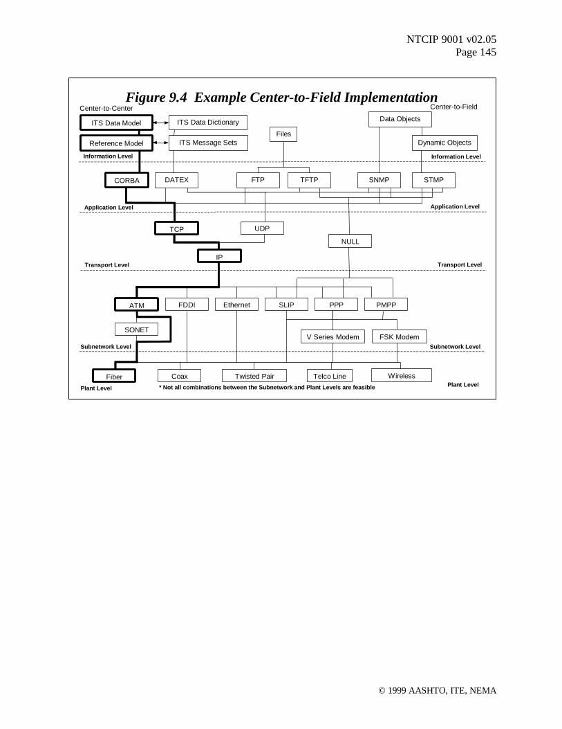
NTCIP 9001 v02.05Page 145
© 1999 AASHTO, ITE, NEMA
Center-to-Center
Plant LevelPlant Level
Figure 9.4 Example Center-to-Field Implementation
SLIP PPP PMPPFDDI Ethernet
Twisted Pair Telco Line Wireless
V Series Modem FSK Modem
Fiber Coax
UDPTCP
IP
NULL
DATEX TFTP SNMP STMPFTPCORBA
Transport Level
Subnetwork Level
Application Level
Information Level
Transport Level
Application Level
Information Level
Subnetwork Level
Dynamic Objects
ITS Data ModelFiles
Data Objects
ATM
SONET
ITS Data Dictionary
ITS Message SetsReference Model
Center-to-Field
* Not all combinations between the Subnetwork and Plant Levels are feasible

NTCIP 9001 v02.05Page 146
© 1999 AASHTO, ITE, NEMA
10 NTICP DOCUMENTS
The following list of NTCIP documents is dated August 20, 1999.
10.1 Listing of NTCIP Documents
Table 10.1 Listing of Current and Planned NTCIP Documents
Number Old Number Title Type Status
1101 TS 3.2-1996 NTCIP Simple Transpn. Mgmt. Framework (STMF) Base Standard Published with NEMA cover; Amended
1102 OER NTCIP Octet Encoding Rules (OER) Base Standard User Comment Draft
1103 STMP NTCIP Simple Transpn. Mgmt. Protocol (STMP) Base Standard WG Draft
1201 TS 3.4-1996 NTCIP Global Object (GO) Definitions Device Data Dictionary Published with NEMA cover; Amended
1202 TS 3.5-1996 NTCIP Objects for ASC Device Data Dictionary Published with NEMA cover; Amended
1203 TS 3.6-1997 NTCIP Objects for Dynamic Message Signs (DMS) Device Data Dictionary Approved by 3 SDOs
1204 TS 3.7-1998 NTCIP Objects for Environmental (ESS) Device Data Dictionary Approved by 3 SDOs
1205 TS 3.CCTV NTCIP Objects for CCTV Camera Control Device Data Dictionary Recommended Standard
1206 TS 3.DCM NTCIP Objects for Data Collectn. (DCM) Device Data Dictionary WG Draft
1207 TS 3.RMC NTCIP Objects for Ramp Meter Control (RMC) Device Data Dictionary WG Draft
1208 TS 3.SWITCH NTCIP Objects for Video Switches Device Data Dictionary User Comment Draft
1209 TS 3.TSS NTCIP Objects for Transp. Sensor Sys. (TSS) Device Data Dictionary User Comment Draft
1400 TCIP-FRAME TCIP Framework Standard Process & Control Recommended Standard
1401 TCIP-CPT TCIP Common Public Transpn. (CPT) Objects Device Data Dictionary Recommended Standard
1402 TCIP-IM TCIP Incident Management (IM) Bus. Area Std. Device Data Dictionary Recommended Standard
1403 TCIP-PI TCIP Passenger Information (PI) Bus. Area Std Device Data Dictionary Recommended Standard
1404 TCIP-SCH TCIP Scheduling/Runcutting (SCH) Bus. Area St Device Data Dictionary Recommended Standard
1405 TCIP-SP TCIP Spatial Representation (SP) Bus. Area S Device Data Dictionary Recommended Standard
1406 TCIP-OB TCIP On-Board (OB) Objects Device Data Dictionary Recommended Standard
1407 TCIP-CC TCIP Control Center (CC) Objects Device Data Dictionary User Comment Draft
1408 TCIP-FC TCIP Fare Collection (FC) Objects Device Data Dictionary User Comment Draft
2001 TS 3.3-1996 NTCIP Class B Profile Profile - Other Published with NEMA cover; Amended
2002 CP-CLA NTCIP Class A and C Profiles Profile - Other Withdrawn
2101 SP-PMPP/RS232 NTCIP SP-PMPP/RS232 Subnet Profile User Comment Draft
2102 SP-PMPP/FSK NTCIP SP-PMPP/FSK Subnet Profile Proposed New Work Item
2103 SP-PPP/RS232 NTCIP SP-PPP/RS232 Subnet Profile WG Draft
2104 SP-Ethernet NTCIP SP-Ethernet Subnet Profile WG Draft
2201 TP-Null NTCIP TP-Null Transport Profile Proposed New Work Item
2202 TP-INTERNET NTCIP TP-Internet (TCP/IP and UDP/IP) Transport Profile Recommended Standard
2301 AP-STMF NTCIP AP-STMF Application Profile Recommended Standard
2302 AP-TFTP NTCIP AP-TFTP Application Profile Recommended Standard

NTCIP 9001 v02.05Page 147
© 1999 AASHTO, ITE, NEMA
Table 10.1 Listing of Current and Planned NTCIP Documents
Number Old Number Title Type Status
2303 AP-FTP NTCIP AP-FTP Application Profile Recommended Standard
2304 TS 3.AP-DATEX NTCIP AP-DATEX-ASN Application Profile User Comment Draft
2305 TS 3.AP-CORBA NTCIP AP-CORBA Application Profile User Comment Draft
2500 InP-C2C NTCIP EP-C2C Center Information Profile WG Draft
2501 InP-DATEX NTCIP EP-DATEX Center Information Profile Proposed Work Item
2502 InP-CORBA NTCIP EP-CORBA Center Information Profile Proposed Work Item
7001 NAN-1 NTCIP Assigned Numbers (NAN) - Part 1 Registry WG Draft
7002 NAN-2 NTCIP Assigned Numbers (NAN) - Part 2 Registry WG Draft
8001 White Paper NTCIP Standards Development Process Process & Control WG Draft
8002 None NTCIP Standards Publications Format Process & Control Committee Draft
8003 TS 3.PRO NTCIP Framework and Classification of Profile Process & Control Approved by Joint Committee
8004 SMI NTCIP Structure and Ident. of Mgmt. & Info. (SMI) Process & Control Proposed New Work Item
9001 Guide NTCIP Guide Information Report Published; Revision Drafted
9002 None NTCIP VDOT Case Study on VMS Information Report Project Draft
9003 None NTCIP WashDOT Case Study on VMS Information Report Project Draft
9004 None NTCIP Phoenix Case Study on Signal Control Information Report Project Draft