Embed Size (px)
Citation preview
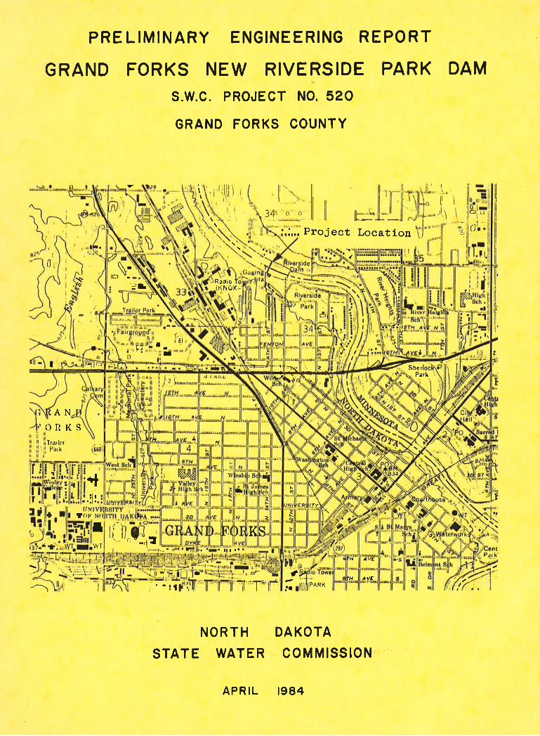
PRE LIMINARY ENGINEERING REPORT
GRAND FORKS NEW RIVERSIDE PARK DAMs.w.c. PRoJEcr No.520GRAND FORKS COUNTY
It
v a.il
'*',. li
i,41
frll
@o
34s ¿j (t
U
,'-:l l'.-][=lË
.;,.. Project Location
ide
e.'a PARK
DA KOTAcoMMtsstoN
t
. ltt.'
¿
ANORKSTra iler
Par k
I
I'N!oF
*l: ll¡..il.
I t{ llP¿rk
ITJ
t-
il f
NORTHSTATE WATER
0
RadioK oxN
or\
f _rl
Ef
\.\\'l.:'t - -
8t
Tt
r¡ + ( ¿ SherPä¡k
LtttIE
Ìt-øw ¡S¡
.r8n9 ¡ tsIA
:¿
.T
I ¿ß
AI'E
'H VE
APRIL 1984
PRELIMTNARY ENGINEERTNG REPORÍ
GRANÐ FORIGS NETü RI\rER,SIDE PARK DAMSWC PRO.]ECT #520
APRTL, L984
NorÈh Dakota State Ítater ComrnissionStaÈe Office suilding
900 E. BoulevardBismarck, ND 58505
PREPARED BY:
ROI{ALD A. S9ÍANSONDesiqn Enginee¡
BY:
r
A.Ðinector of Engineering
APFROVED BY:
VERNON FAIIY, .E.SLate
Prepared for theCity of Grand, ForkS
GRAND FORICS RIVERSIDE PARK DAI\4svüc PRo,fEcT #520
I. INTRODUCTION
In September of L977, the North Dakota State Water Commission
entered into an agreement with the City of Grand Forks to investigate
the feasibility of constructing a new water supply dam on the Red River
(See Appendix A). The purpose of the structure would be to replace the
existing dam which was initially constructed in 1925 and is in an ad-
vanced state of disrepair. It has been repaired several tirnes and is in
such a cond,ition that it could fail at any time.
The purpose of this study is to determine the feasibility of con-
structing a new \^rater supply dam just d.ownstream of the existing dam or
at some other possible location. Surveys and soundings have been made
of the imrnediate downstream area and two test holes have been drilled.
The proposed dam and its features and effects will be evaluated. Con-
clusions and reconunendations will be made regard.ing the possible future
studies and investigations required to make the final decision as to the
details of the proposed dam.
-l-
II. DESCRTPTION OF STTE
Grand Forks Riverside Park dam is an old. rock fitled timber crib
dam located on the Red River of the North in Section 34, Township 152
NorÈh, Range 50 V'Iest, Grand Forks, North Dakota. It was constructed inL925 aE an approxj¡nate cost of $75r700, to provide partial storage forwater supply for the City of Grand Forks. The rest of the Cityrs needs
are meÈ by water from Èhe Red Lake River in Minnesota.
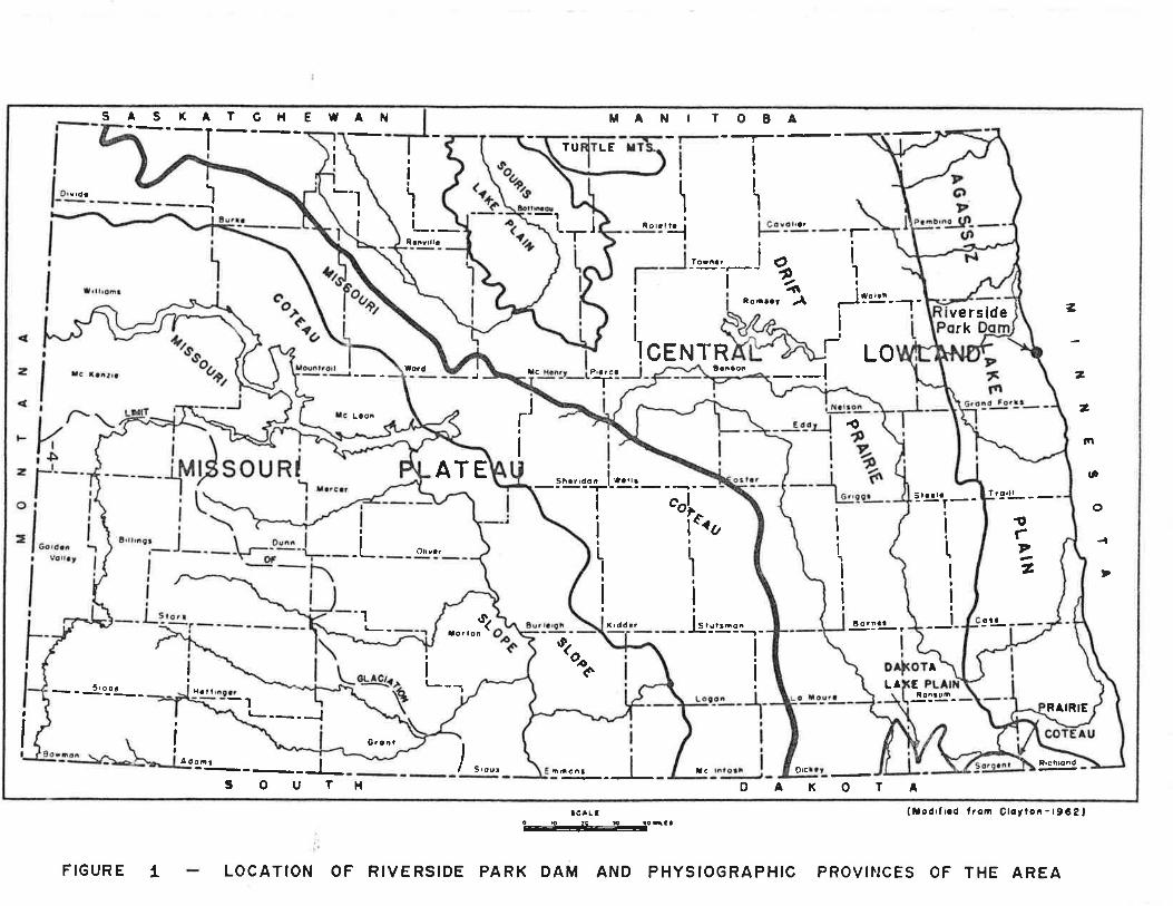
The site presently under consideration is about 600 feet downstream
of the existing d.am and is located in Section 33, Township 152 NorÈh,
Range 50 Vüest. Figure 1 is a map showing the general location of the
d.am and the surficial geology of the area.
The drainage area at the dam is about 301100 square miLes. The
average slope along the main channel is 0.4 feet per mile. Within the
basin the land is used prirnarily for agriculture and the averagie annual
precipitation ís 20 inches.
Near surface sedj:nents along the Red River in Èhe Grand Forks area
are comprised. primarily of clay and. silt deposited by the Red Ríver or
by glacial Lake Agassiz. Along the Red River, up to 20 f.eeL of alluvium
directly underlies Iand surface. The alluvium is prinarily clay and.
silt with some fine sand, reflecting the sediments in the Red. River
drainage basin. The recent alluvium is underlain by approximately 80
feet of lake sediments. The lake sedimenÈs, Iike the alluvium, are
primarily silty clay with occasional sand lenses. In places, reworked
glacial till is present within the l-ake sediments. Approximately 100
feet of glacial tiII underlies the sediments deposited, in glacial Lake
Agassiz. The glacial Èi11, in turn, is underlain by up to 20 feet ofsand and. gravel. The sand and gravel is either glacial outwash or
-2-
preglacial atluvium overtying bedrock. Ordovícian !{innipeg group bed-
rock underlies the area at approxJmately 200 Èo 22O fee| bel-ow land
surface.
-3-
SASXATCHEWAN MANIl ooa---- I fU LE
!
IIv'(tt ì *-la
I
\I \
aqI I L I tlot.l af
a
I1I
R tnrrlla
l!
\
Tor¡¡r
I
oe4t JI
-
loôr.t .å f o ltlr----1 7
2CENTR LO
l@d Tc Pr c! ta¡¡æ ---lLaoñ
--r¡
/I
2
fn
(D
o
-a
Sh!r'd o ' I ".,,,I c^l"1"'o
¡
li
Slaata
.L O¡vcr
,
II
LI¡
II
itIIIII1t-- t I tddc? lr,,rr-o.&----t-
I
i
Xor Ioñ
I II
It-t
-- s'gf" _ IHalI l
a
,I
, -_-_JG.cã)
IAdoo¡ I nrchlonó---__30uSrour Xc O'c
1H oAl(ofA
RAIRIE
ctú
!fz
9'll- - -1¡
Ë0iñat
iII'1
I
iI
A
{
ELA¡lo^toñ
ve rs iderk
)onê
ATE
¡crLl (taoórfr.d lTor'l Clotton - 1962,o----L¡g----g-.-!c r I i
FIGUR E 1 LOCATION OF RIVERSIDE PARK OAM ANO PHYSIOGRAPHIC PROVI¡¡CES OF THE AREA
IfI. HYDROLOGIC ANALYSIS
A hydrologic sÈudy has been sponsored by the U.S. Department of
Housilg and Urban Development to invesÈigate the existence and severity
of ftood hazards in the City of Grand Forks, North Dakota and to aid in
the administration of Èhe Flood Insurance Act of 1968 and the Flood
Disaster Protection AcÈ of 1973. The results of this investigation were
published in the Flood Insurance Study, <lated September 1977 -
The Water Resources Division of the U.S. Geological Survey fur-nished valuable assistance by providing basic hydraulic data pertaining
to the study area. Survey data, historical flood profiles, and delinea-
tion of areas flooded for past events were obtained by contacting the
U.S. Army Corps of Engineers, St. Paul District. The North Dakota State
Water Conunission and the City of Grand Forks, Engineering Department,
furnished data and cooperated in the stud.y. An interagency group meet-
ing in Fargo, North Dakota, held on December 12, L973, agreed to accept
the 89,000 cubic feeÈ per second as the 100-year flood discharge at
Grand Forks.
The flow-frequency d.ata used for Èhe 100-year flood on the Red
River of Èhe North was coordinated by the states of Minnesota and North
Dakota, U.S. Army Corps of Engineers, U.S. .Geological Survey, and the
Soil Conservation Service, under an interagency agreement.
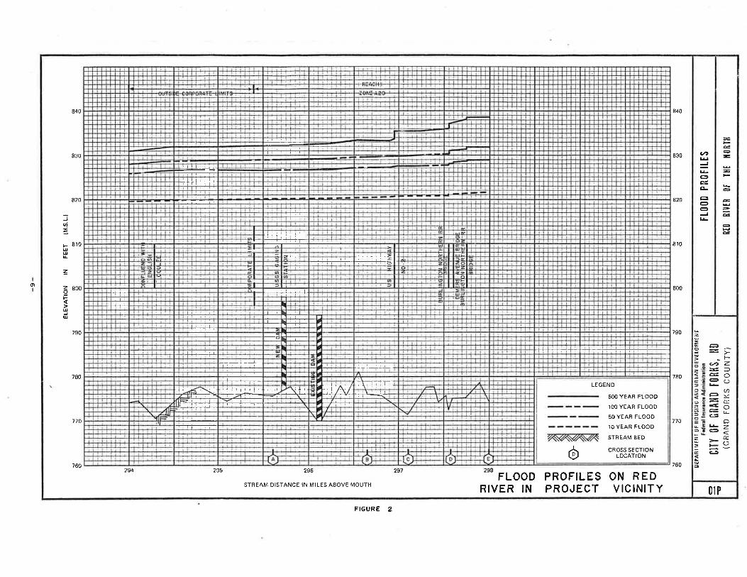
The Red River flood profiles at Grand Forks are shown in Figure 2.
Ho\^¡ever, as a result of t.he 1979 flood on the Red River, the Corps of
Engineers has now revised, the 100-year flood flow at Grand Forks to be
about l-06,000 cubic feet per second. This revision is defined in the
Grand Forks - East Grand Forks Urban lrlater Resources Study - Flood
Control Append.ix - Corps of Engineers, St. PauI District, JuJ-y 1981.
-5-
9
et -t
¡rEPA
ßil¡E
?rr 0
t ilo
usll¡
G A
ri0 u
n$AN
0Ev
Ér-o
tMttJ
I
ctTY
0t û
tlA}l0
t0Rt
{s, l
l0(G
RAND
FO
RKS
COUN
TY)
RIO
RIY
IR O
I TllE
IIO
RTll
tt00D
Pn0
iltEs
lt
E tï II
jlflf
rril ffi
58 ä
3;??
iä3i
?ii
ojm
-rÍT
=õog
R65
z ó
õgg
er m d) r z I
il1
Li
IJ, rII ïtt ffilIftr
+
ï II H il el r[ï
I1$tï
lt{+
rl
ïil
{{{{
o{@
@oo
oo6@ õo
ó6@
NQÀ
ooo
! o o{ { o
ÈÈËä
@@
ño oo
ELEV
ATIO
N IN
FE
ET (M
.S.L
.)
N @ N @
¡ - m v =
@ @
{ T m = o + 2 o m 2p <3 m @ o m s o c I -
ñ @
-rl r o o IT.
I' vv oo C- T
Irn
=qi
n-l
92 =2c) É ¡rl
-'l I
@ o
l 6) c ¡ m N
IV. HYDRAULIC ANALYSIS
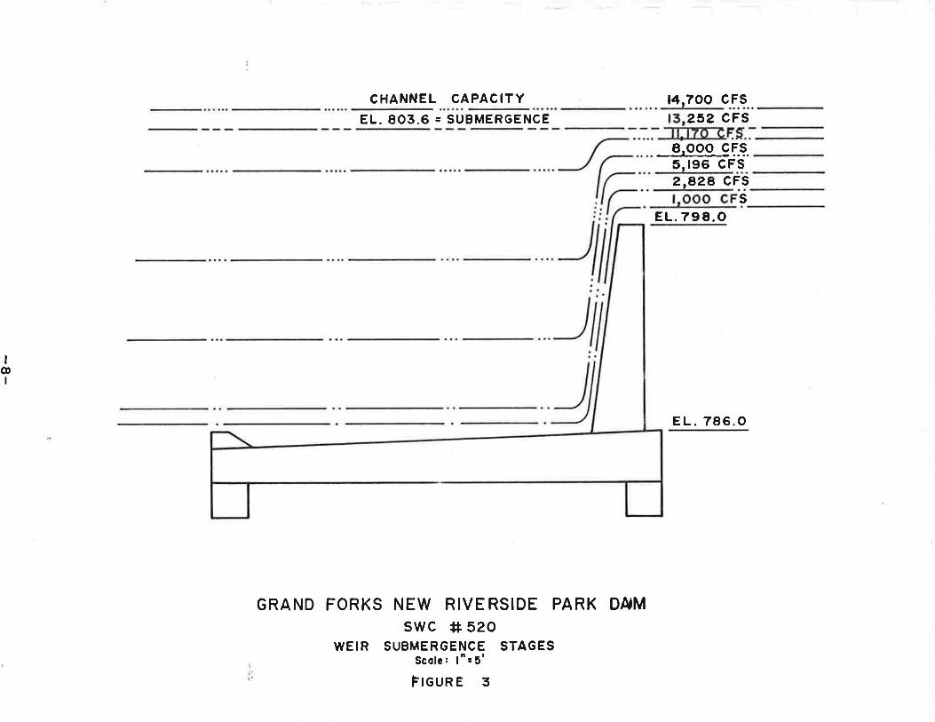
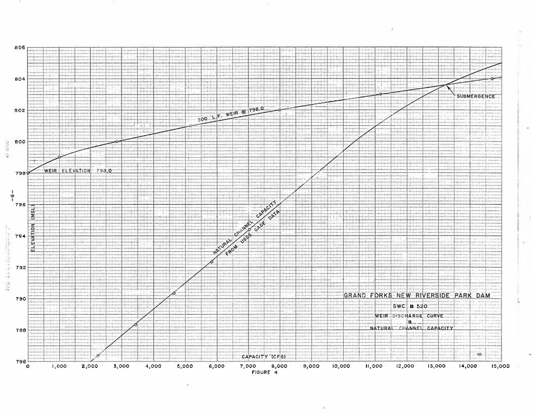
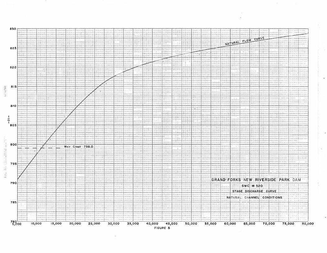
The new dam will be designed to pass the expected flows without
causing any increase in any flood flows. The dam will have a 300 foot
Iong weir set at an elevation of 798.0 msl. The side sloPes will con-
form to the natural ctrannel banks. In order to preselî\¡e laminar flow,
the dam will operate under weir flow control until the weir submerges
and the natural ct¡annel controls the flow. This occurs at an elevation
of 803.6 msl and a discharge of 13,250 cfs as is shown in Figure 3, 4,
and 5.
The changeover from weir control to channel control- shoul-d occur
within an elevation range of l-foot with only a minor amount of tur-
bulence. Thereafter, the flow should continue in a normal channel flow
state with no turbulence or ripples indicating r^¡here the completely
submerged structure is located.
Erosion and damage to the channel and river banks will be kept to a
minimum with reasonabl-e amounts of rock riprapping. Extraneous effects'
caused. by floating tree trunks trapped. at the dam structure, may create
certain turbulent and erosive currents. Tree trunks should be removed
as soon as possible.
Another factor to be consid.ered is ice jarns. The size and effect
of these buildups can vary considerably and are difficul-t to predict and
evaluate.
. Laboratory model studies should be made for the proposed. dam before
final plans are prepared. Results of the hydraulic tests serve as part
of the design criteria.
-7-
CHANNEL CAPACITYEL. 803.6 = SUBMERGENCE
GRAND FORKS NEW RIVE RSIDE PARK DA'Mswc # 520
WEIR SUBMERGENCE STAGESScolc: ltt=5tFreune g
14,700 cFs252 CFS
8.OOO CF.S5,196 CF s2,828 CFS
sEL.798.O
EL.786.O
I@
I
XY TC-7
=t- cll
ÃFGEg___.iNNEI.
*ù 52
--+:-- -NE)R KÍIDF_l-
---/ L--!
-+r,+ !-
'{,É..+tl,-
--T--- 'll
- #
-------!_- -T-r-
=---..1_]-
+-l=lr ]- ?r€f L€'VATIOÀ
-...-..--
--++-¡i-- -/+
=Æ-€r
-].. l- +_
----tir;!:t ã--ø¿
' r-'-__---7- i-l] i_-E
-i-.---_r--_i- -
L-ffi'-T- r+__r+-
f--_!--']__
,tÌ-..:l..r Í---rj-Í--+Ì-.-
1)
e06
804
802
800
798
794
79?
790
788
(o
796
:
-¡
7,OOO I,OOOFIGURE 4
786o I,OOO 2,OOO 3,OOO 4,OOO 5,OOO 6,000 9,OOO |O,OOO il,OOO |2,OOO |3,OOO |4,OOO |5,OOO
TURAI-- CH,+-
,lD- E _NE DAM -..E
--t.._
--l
+ t-'eir.'{
'Iitr-.i-+-+-i-
lrt-+-tr+
- - -+i-T--+
-l
I -J-l_Ta+-
rll--l-ï- |-r'- T-:+- ---al
:ir+_l:--!-/
=-<4 -l-
-7
-i--lT--
}_]-!-'ì-t--r+ vE-
ir:
?tc
830
a25
820
8t5
8ro
800
795
79
785
7805,O
I
õI805
OO IO,OOO |5,OOO 2O,OOO 25rooo 3O,oOO 35,OOO 4O,OOO 45,OoO 5O,OOO 55roOO 60,000 651000 7O,OOO 75,OOO 8O,oOOFIGURE 5
V. DAIVT FEATURES
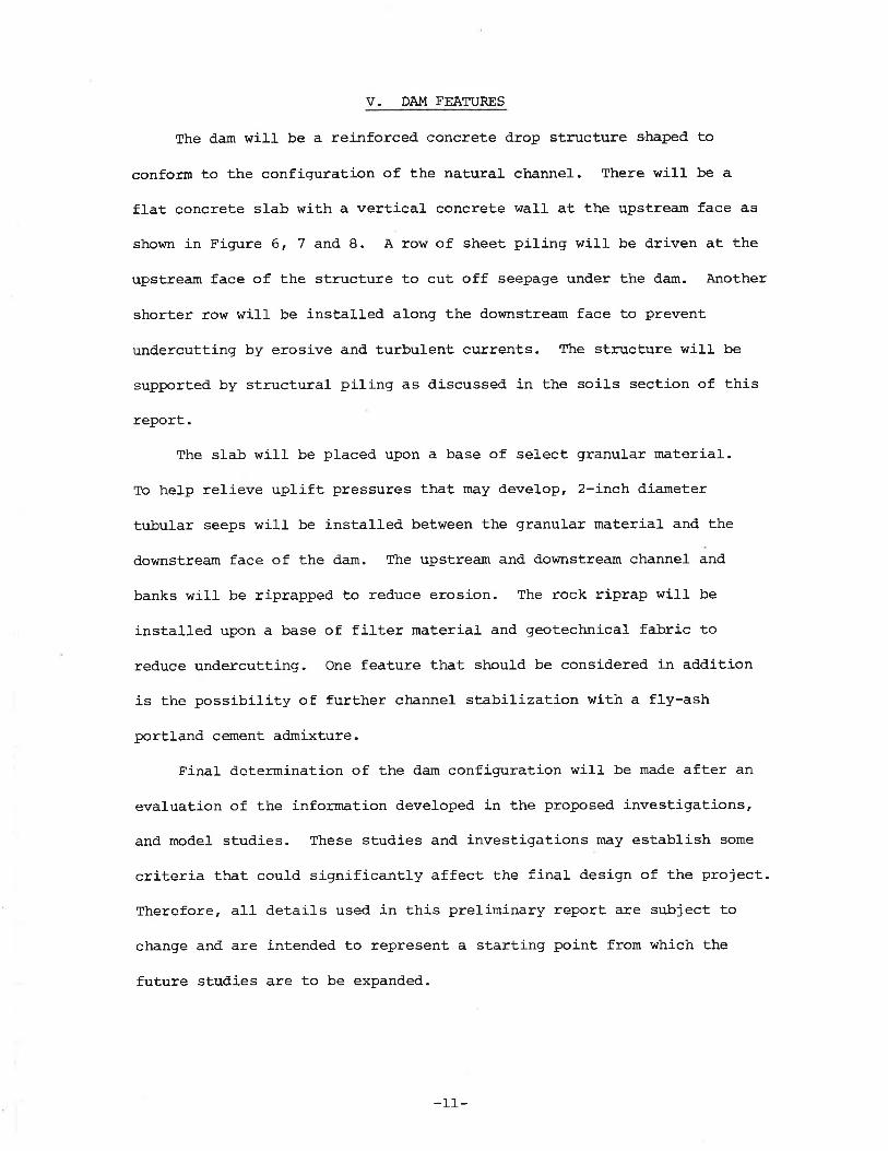
The dam will be a reinforced concrete drop structure shaped to
conform to the configuration of the natural channel. There will be a
flat concreÈe slab with a vertical concrete wall at the upstrea:n face as
shown in Figure 6, 7 and, 8. A ro\Á/ of sheet piling will be driven at the
upstream face of the structure to cut off seepage under the dam. Another
shorter row will be insÈa1led along the downstream face to prevent
undercuÈting by erosive and turbulent currents. The structure will be
supported by structural piling as discussed, in the soils section of this
report.The slab will be placed upon a base of select granular material.
To help relieve uplifÈ pressures that may develop, 2-inch diameter
tubular seeps will be installed between the granular material and the
downstream face of the dam. The upstream and d.ownstream channel and
banks will be riprapped to red.uce erosion. The rock riprap will be
installed upon a base of filter maÈerial and geotectrrical fabric to
reduce undercutting. One feature that should be considered. in additíon
is the possibility of further channel stabilization with a fly-ashportland cement admixture.
Fina1 determination of the dam confignrration will be made after an
evaluation of the information developed in Èhe proposed investigations'
and model studies. These studies and investigations may establish some
criteria that could significantly affect the final design of the project.
Therefore, all detail-s used in this preliminary report are subject to
change and are intended. to represent a starting point from whích the
future studies are to be expand.ed.
-ll-
: El. 798.O
Et. 7 7t.o
Selecl Fill
a3
ao
oõooB
Select Gronulor F¡ll
C,oo ôos
El.78t.O
{ (' {I{ Ii {{ t¡t I
¡r¡{{{ .t 1: ( i{{ {{
t.lc {.1
{t
Ia
{1'
{
Rock Riprop
Selecl F¡ll
Et. 786.O
Sheet Piling
GRAND FORKS NEW RIVERSIDE PARK DAMswc # 52O
TYPICAL SECTIONScoll: l
t'= 5'FIGURE 6
Et.786.O Rock Riprop
EIEr.78l.O
Selecl F¡11
El. 777.O
-
IñI
Et. 762.O

55'
400'
Weir E1.798.O
GRAND FORKS NEW RIVERSIDE PARK DAMswc *+ 520
PLAN A ELEVATION VIEWS - NEW WEIR STRUCTUREScc le : ltt = 5o'
FIGURE 7
35'
@N
PLAN
-I
(rlI Et. 8t5.O !
E1.762.O
EL EV.
-
50' 3oo' 50'
\ ¿Sheel Piling
!8-s
tì':þ¡,' t
tt.9
7é.9
rå.9
77'9
a9.9
-6¡.?\
s3l
t98.oeoao¿gPe4
o5rt
17.?
q6. t
o€7
g',ôr7
89.7
?,'B
1ô.È
t6. ¡
ETÞS AERÊ
¡1.5
o{.?
10,o
t 7.9
l?.4
ßf14r8
4'ál¡.t
06.4
I ?.q
râ.3
ta.9
l ¿.o
12.Z
03.g.¡.
-.,,
IO.?
oa.1
o!. ô FEIEE
o'lr- ; ot'5---- \.-tt*..-
co'ä
gs.7
#I
û0.1 ""{o¿. ô
os 2- Ósl't
".L --?6.O
ol:5
:81'l
89.e
17.9
?l,e
-ì-rsr zì*
oô.1
o6.!
74,t
a6-q
ô4-ã>Ða-nã
cönoðE€ 0r'?'\_..-.-95:4-
6!,0
?5.1
tsI
I
I
l..!Ilãlo
l3plotã¡-
?Þ6
7a.7
69.1
6t.3
7A.O
oJ.l
04 '8FIGURE 8
65'O
6{.?
69.9
6,O
64.?
I
I
I'l-I
I
IJ
I
I
t
I
?5. r
a5- tî
7a,t617'¿ *! "+
797094
tlt6
qq.t
6?'à
72.2
79.7
ao'?
8r.9 ð1,4
-a5.7+-.- u.r/
1ìO'5
oâ.o'9ó'å
o¡'q
03,?
?8.{ ?O'3Bl 7-':\9+*¿l Lt EIEtr\Ë-r *t ãF-\ I "t!"9?.6
' _---
1t.2
7s'4 ?
c¡.s 1
¡jvTuÈJ t.¿' XGâô¡ êuLvERtt,
I ;| -/'
- 99;O
ø4.¿
€oRçaEfÉ
oa-aso208 0!.4
ozt f
GRAND FORKS NEW R]VERSIDE PARK DAMswc ++ ô20
O4.8SITE LAYOUT A TEST BORING LOCATIONS
o8'1
ot'o
o4.4
03,¡
ðit.ltl'l
ôt.i
O9.9
ró{
p.6.
ã9r 6 99.O6¡.t
07.¿
lo.l
¡2"A
VI. CONSTRUCTION REOUTREMENTS
The reinforced concrete weir structure will be constructed. in two
phases. A cofferdam should be constructed out from one bank and. pro-
tected with temporary riprap. The area within the cofferd.am would Èhen
be dewatered. Upon completion of Èhe dewatering, the bottom material
within Èhe coffered area would be excavated. to a depth of approximately
6 feet below the existing elevation. This area would then be backfilledwith a select material. The upstream and d.ownstream rows of sheet
piting and structural piling would then be driven.A select granular material base for the slab would be installed and
the reinforced concrete slab placed. thereon.
The structure would be constructed in sections of about 20 feet inlength. Each segment will be joined to the adjacent member wiÈh steeldowel bars. The joints will be sealed with a rubber expansion jointmaterial. Construction joints bet\¡¡een the slab and vertical walls would
have a steel p1aÈe installed through the joint to provide a cutoff.After completion of the structure, the ad.jacent area would. be
shaped. to grade, filter material and, fabric installed and rock riprapplaced.
If concrete is placed during the winter, the concrete would have tobe heated. and protected, from the elements during the curing period..
The cofferd.am would require upkeep during this entire project. Itis expected that each project phase wiII require about three months ofcontinuous construction. lfith the demolition and replacernent of cofferdams between phases, the project may require a total of seven months.
Assuming that the work could sÈart in JuIy, after the spring runoffhas decreased, the project could run through January or February.
-15-
surrner storms could cause this sched,ule to be extended by a month or
more, resulting in most of the work being accomplished during the winter
months. This may be feasible but the con5Èruction costs will be pro-
portionatelY higher-
-16-
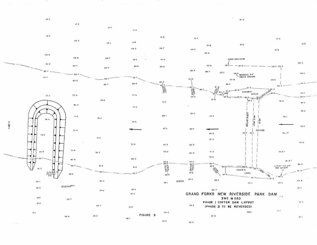
VTI. VÍATER CONTROL DURING CONSTRUCTTON
One very serious consideration in planning the dam construction
program is whether the site can be protected from high flows during
construction. Previous construction work has been accomplished by
cofferdaming one-half of the river at a time. This has apparently
proved to be adequaÈe for a shorter duration effort and may or may not
be sufficienÈ for a project which will require considerable more time.
The layout for the proposed first phase cofferdam is shown in Figure 9.
The assumption is that the horseshoe shaped cofferdam will be
constructed by hauling in a fat, cohesive clay fill and dozing it intothe stream in the d,esired. configuration. The temporary earthen dike,
will be protected with a riprap facing. The cofferdam will require
continual upkeep and repair until the first half of the dam is com-
pleted. At that time, the first phase cofferdam will be demolished. and
the second phase cofferdam will be constructed. It will come out from
the opposite bank in a manner similar to the first cofferdam. Since
this phase will involve flow over the completed weir, instead. of through
a constricted open channel, the elevation of the cofferdam will have to
be proportionally higher.
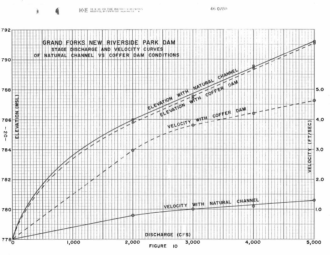
A design flow of 51000 cfs was used as a trial f1ow rate. It \nras
routed through the natural channel and the channel as constricted by the
first phase cofferdam. The details are shown in Figure 10.
The figures show that in the natural channel situation, the fl-ow of51000 cfs would result in a water surface elevation of 79L.ll- msl and a
velocity of I.24 fl/sec. I/üith the cofferdam in place, the \^rater surface
would be 790.91 msl and the velociÈy would be 4.62 ft/sec. This indicates
that the cofferdam would be a feasible proposal, but it will require
-L7 -
rock riprap facinq and considerabl-e maintenanee to survive the erosion
caused. by high ïrater vel-ocities-
Ttre cofferdan will have to be constructed with Èwo or three feeÈ of
freeboard to provide proteetion against sudden rises in river elevation
due to heavy rainfalls. Assr:rning a three month firsÈ Phase consÈruction
schedule, at least one or two of these short intense rainfalls should be
anticipated and planned for in advance. This situation will pose a
probtem for potential contractors-
-L8-
ra.a
tf.t
o5.a
oo. a
FEÙè€
IOaiz-
t6.!
E-!
ETDS]NÊRÈ
---\
l?9
09 I
77.9
t5.9
7?.9
77.9
E,S
\g¡-l- .
a€.3
80804f{
o5.7
06
06.?
so.?
8Þ'?
?r.9
t5.z
7 t.6
75.7
6r.a
'-9!.r--.,
sq.6
Oã'O-
03.7
!7'1
t5'3
7:7.2
l?'3
ll'6
o,4'2
ol.5
90.6
t{-8l?rst4 'l
t¡.? t€.9
ó4.7
09.6oQ,8
9l,O co'7
a3,7 -*
-
6¡.1 =\t|.f --\
t0! o
ol.a
à0'3
8 a.$
oo:3
9¡.o
GRAND
ol'â
oÊ. I
0€.3.-....-..:sr.t
tg-9I l'tÕ
II
-s.7*3Þ .- sr'z.-.ã\q6S:3
dc.?r oo,t
64"2
o8i" ¡¡rxore s'¡'-aBovE äRoorD
---=,-al'1cwcñETf
ÀPÊ0ll
o?'996-6
o4.5
z
I
t,si¿e¡l.l
--dåm7It7
Ò.4 -4+.O--
7'l-à
7t2 I
IIl-ItI
?èi1
0.9'l
67.?
I
I
I1f
tb
leI
9à.3I
lÞ
¡9l.tðtri
e¡,?I
I
III
I
l
7€'O
o4,2
DAMê '.1
73.8
't.5, t?
v4.o
tg' 4:l
!1.6 ?86.O
95,ô
?t.¡
?l'9 t5. I7+.9
I
õI
to.o
72,2
ao'2
Ê4.7 .a-.Éq€r€
6?'9
Ê9.9
7t.965. O
7¡, ?
70.3s-?--".-45'?\ll9 Þe:ß àsàlfi "æ\@'? a2.4
7970987t.è
a!.9,
9t.5
06.l
o€. ã
lz't
67.¡
ro.0
73.48l'7 .-3\9t\oule?'6
-8t',¿"'
ôl;0
G.5
st.4-/
ò4.+
I ?.O
90. I
ao208o!. t of- t
o2'7FORKS NEW RIVERSIDE FARK
sWC r+ 520PHASE I COFFER DAM LAYOUT
(PHASE tr TO BE REVERSED)ôú. o
õ7. O
o. t.9
04.6to.l
t?6
ot.6 æ.ool. I
FIGIJRE 9o?,9 oa.9
o
Ê5
{lrl-.8 f0 X l0 ìO fllE l¡lctl!, \\ l{) l'¡, rlr'lñ\"é xr.t lr I r:t- & F'i1I R ri() tr1,rr r{ ,r 1
^
4Ét 0780t
5.O
4.O
3.O
2.O
t.o
(I/
I
I
)I,
IIIIiI
I
jI
t\
/. \It
IIt\
/ a//
l
i
I
I
III
I
IIl
Illil
r
l
I
1
aI
I
I
)
-tI
rl(I
II(
\\
I
1
l
\IN
I
0Y
III
I
iI
D
il
Lf tA )vIti
^I
I
I
(E'l
l/
I
ì
iIIIq
l
I
I
I
I
I
I
792
790
788
786
784
782
780
I
tuoI
SrOOO4|OOO3,OOOFIGURE IO2,OOOI,OOO77
VIII. SOILS INVESTIGATION
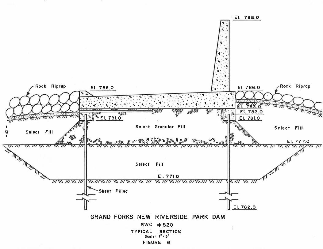
A prelirninary subsurface investigation was performed by a soils
engíneering consultant. Íræ d,rill hoJ-es were mad,e¡ onê on either síd.e
of the river just downstrean of the existing dam as sho!ûn in Plgure
8- The soils investigation report is lncluded in Appendix B.
The limited scope of this initial investigation serves to indicatethat a much more detailed investigation will be required bef,ore the
final design of this projecÈ can be completed. The tlpe and, J-ength ofstructural piling required was d.iscussed, buÈ not in detail in the soí1s
report. A second area that will require study is the tlpe and lenEth ofsteel sheet piling that will be needed for upsÈrean and downstream
cutoff purposes. The Èhird concern Ls the slope stability of the riverbanks. This is certainly an important factor that must be fully eval-uated. A subsidiary consideraÈion could be possible of stabilizaÈionwith fly-ash and portland cement.
-2t-
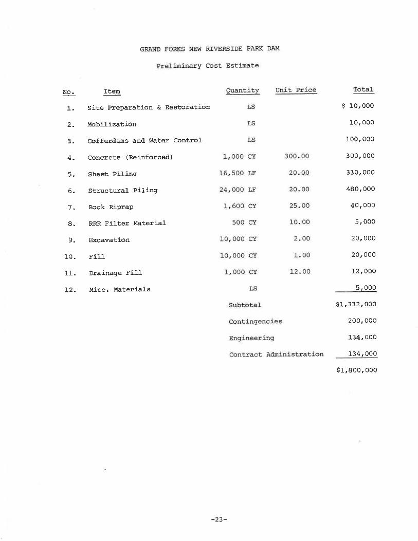
IX. PROJECT COSTS
Since the project is still in the preliminary investigation stage,
any cost estimaÈe for the project must be of a preliminary nature. f?le
basic concept for the design is reasonably close to what the finat
design will be, thereforer the costs should be close enough for general
project financial- planning. As is shordn in the detailed cost esÈimate
below, all anticipated costs have been identified. The most reasonable
quantit,ies and þrices (1984 construction season) have been used. If the
project is d.elayed several yearsr. inflation may escaJ-ate these prices.
La,nd acquisition costs are not inch.rded in this estimate anp must
be added. It is anticipated that the city will be abJ.e to acguire the
].and,.
Tt may be desired to look at the feasibility of constructing the
dam at a different site than the one considered. This may also change
the costs.
Hov¡ever, it is still considered that Èhe estimate should be cl-ose
enough to cover some reasonable changes or relocatíons.
GRA}T.D FORKS NEV{ RTVEESIDE PARK DAI4
,Preljminarl¡ Cost Estimate
No.
1.
2.
3.
4.
5.
6.
7-
8.Ò
10.
1r.
L2.
Item
SiÈe Pfeparation & Restoration
Mobil-ization
Cofferda¡ns and !Íater Control
concrete (Reinforced)
Sheet Piling
Structural PilingRock RiPraP
RRR. Filter Material
Excavation
Fi11
Drainage Fi1lMisc. Material-s
guantitlr
rsLS
Unit Price
LS
L,ooo cY 30o.0o
L6,50o LE 20.00
24, 000 r,r 20. 00
1,600 cY 25.00
500 gs 10.00
1on0o0 cY 2,OO
101000 cr 1.00
L,ooo cY 12.CI0
LS
Subtstal
Contingencies
Engrinee::ing
Contract Ad¡ninlstration
Total
$ 10,000
10, o0o
10o, 000
300, ooo
33O, 000
480, 000
40, 000
5, 0oo
20, 000
20,0o0
12, o0o
5,000
$1, 332, 0oo
200,00o
134, ooo
134, O00
$1,80O,O00
-23-
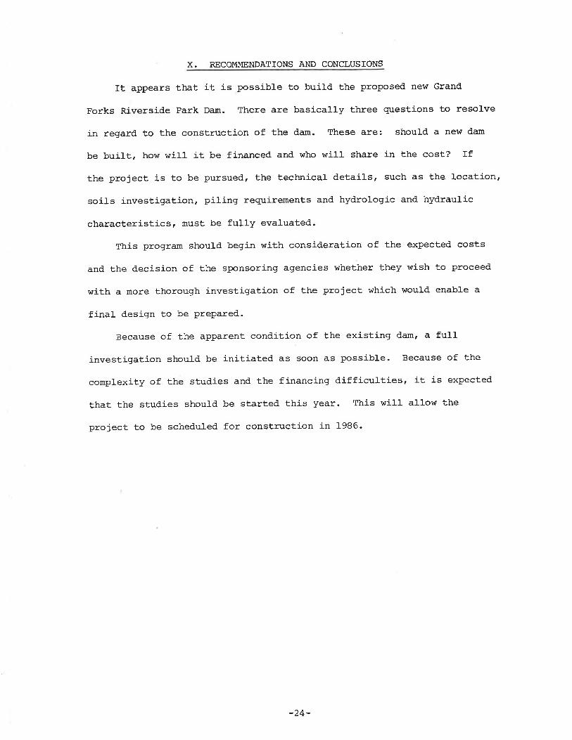
X. RECOMMENDATIONS AND CONCLUSIONS
It appears that it is possible to build the proposed new Grand
Forks Riversid.e Park Dam. There are basically three questions to resolve
in regard to the construction of the dam. These are: should a new d'am
be built, how will it be financed and who will share in the cost? If
the project is to be pursued, the technical details, such as the location'
soils invesÈigation, piling requirements and hydrologic and hydraulic
characterisÈics' must be fully evaluated.
This program should begin with consideration of the expected costs
and the decision of the sponsoring agencies whether they wish to proceed
with a more thorough investigation of the project which would enable a
final design to be PrePared.
Because of the apparent condition of the existing dam, a fulI
investigation should be initiated as soon as possible. Because of the
complexity of the studies and the financing d,ifficulties, it is expected
thaÈ the studies shoul{ be started this year. This will allow the
project to be scheduled for construction in 1986-
-24-
. APPENDIX A
Project Investigation Agreement
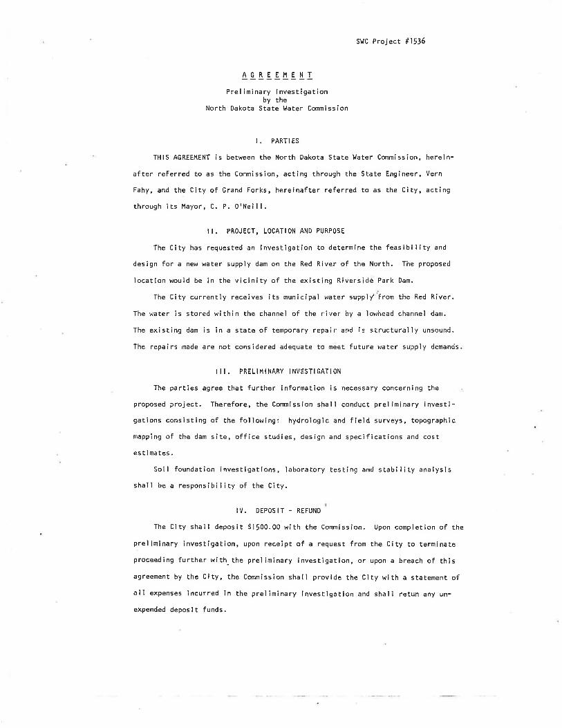
StrC Project #1536
Prel imi nary I nvesti gat ionby the
North Dakota State Water Cornmission
I . PARTI ES
THIS AGREEMENT is between the North Dakota State llater Commission,
after referred to as the Commission, acting through the State Engineer,
Fahy, and the City of Grand Forks, hereinafter referred to as the City,through its Hayor, C. P. 0rNei I l.
ô!_tE_E r_!.I-l
here i n-
Vern
act i ng
il. PRoJECT, LoCATIoN AND PURPoSE
The City has requested an lnvestigation to determine the feasíbility and
design for a new water supply dam on the Red River of the North. The proposed
location would be in the vicínity of the existing Riversidè Park Dam.
lhe City currently receives its municipal water suppìy from the Red River.
The water is stored within the channel of the river hy a ìov¡head char¡nel dam.
The existing dam is in a state of temporary repeir and Ís structuraìly unsound.
The repairs made are not considered adequate to meet future water supply demands
I I I. PRELIMINARY INVESTIGATION
The parties agree that further information is necessary concerning the
proposed project. Therefore, the Commission shal I conduct prel ìminary investi-getíons consisting of the fol lowing: hydrologic and field surveys, topographic
mapping of the dam site, office studies, design and specifications and cost
est ¡ ma tes .
Soil foundation investigations, laboratory test¡ng and stability analysis
shall be a responsibility of the City.
IV. DEPOSIT - REFUND
The City shalì deposit S1500.00 with the Commíssion. Upon completion of the
preliminary investigation, upon receipt of a request from the City to terminateproceeding further with-the preliminary investigation, or upon a breach of th¡sagreement by the city, the commlssion shall provide the cíty with a statement ofall expenses incurred in the preliminary investîgation and shall retun any un-
expended deposlt funds.
-t-
V. RIGIITS OF E}'ITRY
The Oity agrees to obtain wrltten permission from any aff,ected landov'lner
for surveys or subsurface lnvestl.gations by the Conrnission (or any contt'actor)
which are requlred for the preliminary lnvegtlgation .
vl. tNDEt4NlFtcATlol'¡
The City her.eby âccepts r:eponsiblllty for, and holds the Comnission free
from, all clalms and damages to public or private propert¡esr riEhts, or persons
åris¡ng out of this Investigâtlon. ln the event a sult ls l'nltlated or judgment
entered against the Commisslon, the Board shall indefünîfy it for" any judgmçnt
arrived at or judgment sat¡6fled.
CITY OF ORAND F.ORKS NORTH DAKOTA STATE T.IATER CO}IMISSION
Septe$ber 2A, L9'17Dâte
tl--,:J"t --Vern Fãliy -State Englneer
September 8, 1977Date
0
APPENDIX B
T\lvin City TestingSubsurface Exploration Report
REPORT OF SUBSURFACE EXPLORATION PROGRAM
PROPOSED LOI{ HEAD DAM
RIVERSIDE PARK
GRAND FORKS, NORTH DAKOTA
#120-11173 and #54-1065
I NTRODUCTI ON
l,le understand that a nerú reinforced concrete low head dam will be constructeda short distance downstream of the existing dam in the Riverside Park area ofGrand Forks, North Dakota. l,'le further understand that present plans call forthe concrete dam to be supported on a driven pile foundation.
l'le have performed a subsurface exp'loration program and engìneering review forthe proposed cosntruction. The scope of our exp'loration program and engineer-
ing revie¡{ on this project is as follows:
1 To put down two standard penetration test borìngs in thelocation of the proposed dam.
To perform laboratory tests on representative so'i1 sampìesin order to estimate pertinent soi'l parameters.
To recommend driven piìe types and estimate requìred pilelengths and recommended harnmer energies for the propirsedpile foundation.
2
To perform a preììminary review of the potential embankmentstabìlity at the site.
This report presents the results of the field and laboratory testing. Alsopresented are our recommendatjons based on a review of the field and ìaboratorydata.
3
4
Èumcltl, È¡l¡Èrnc¡
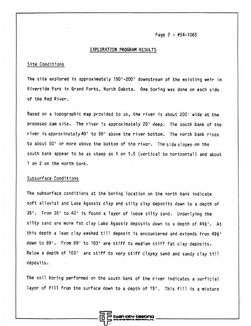
Page 2 - #54-1065
EXPLORATIOII PROGRAI.I RESULTS
Site Cond'itions
The site explored is approximately 150'-200'downstream of the existing weir jnRiverside Park jn Grand Forks, North Dakota. One boring was done on each side
of the Red River.
Based on a topographic map prov'ided to us, the river is about 200'wide at theproposed dam site. The river is approximateìy 20'deep. The south bank of theriver is approximately40' to 50' above the river bottom. The north bank risesto about 50' or more above the bottom of the river. The side s'lopes-on the
south bank appear to be as steep as 1 on 1.5 (vertical to horizontal) and about
1 on 2 on the north bank.
Subsurface Conditions
The subsurface cond'it'ions at the boring location on the north bank jndicate
soft alluvial and Lake Agassiz clay and s'i'lty c'lay deposits down to a depth of35'. From 35'to 40'is found a layer of loose si'lty sand. underlying thesilty sand are more fat clay Lake Agass'iz deposits down to a depth of 49*'. Atthis depth a lean clay washed tilì deposit js encountered and extends from 49*'down to 89'. From 89'to 103' are stiff to medium stiff fat clay deposits.Below a depth of 103' are stiff to very stiff c'layey sand and sandy c'lay tÍì1depos i ts .
The so'il boring performed on the south bank of the river indicates a surficia]layer of fill from the surface down to a depth of 15'. Th'is fjll is a mjxture
Èu.rl Ctr, ÈEJtrtìcl
Page 3 - #54-1065
of silty sand and clayey sand with some gravel and other debris. Under'lying
the fill are deposits similar to those encountered in boring 1. The depth tothe stiff till deposits is 108'.
The attached boring ìogs indicate the layering of the soil deposits encoun-
tered at the two borings.
Ground water measurements were made at the times and levels as ind'icated on the
attached boring ìogs. Due to the cohesive nature of the soils, the measured
water levels may not be reliable ind'ications of the true steady state water
table. Normally, extended periods of time are needed to estabìish steady statewater tables in very cohesive soìls such as found on this site.
The river level undoubtedly governs the location of the water table on both
sides of the river.
ENGINEERING REVIEt.l AND RECOMMENDATIONS
Pro.'iect I nf ormati on
Our understand'ing of the proposed construction is rather limjted at this t'ime.
l,le understand that the structure will be a low head dam mainìy constructed ofreinforced concrete. We understand that it is p'lanned to support the structureon a driven pile foundation. l.le have no information regarding any earthworkor other loadings to be placed on the river banks.
The scope of this report is just to address the loads, recornmended depths, and
har¡mer types for the p'lanned pi'le foundation. tle also w'ill address jn a
Èu.rìctv Ec!¡trrt¡rÉG¡ImErIEr¡E
Page 4 - #54-1065
preliminary ¡{ay any potentiaì embankment stabiìity problems. Additionalreview and possjble testing may be required to better determine the stabìljtyprob'lems after we have a chance to review the construction plans.
Foundati on Reconunendati ons
It is our opinion that a driven pile foundation for the proposed concrete dam
is the optimum foundation support system. l.le have no information re-garding the required loads for this project; however, we feel that any piìingdriven would have to penetrate at least a few feet into the hard clay ti'l'ldepos'its found at a depth of 103' in boring 1 and 108'in boring 2.
In our opìnion, the most feasible pìle types would be a heavy walìed 7-518" 0r
9-518" 0.0. steel pipe pììe. The 7-518" p'ile can accornmodate loadings of up
to about 60 to 75 tons per pile. This pile would probably penetrate about 3'
to 5' into the hard clay till to develop these loads. Piling of this type
should be driven with a har¡mer havinE an energy rating on the order of 18,000
to 25,000 ft-lbs.
If h'igher loads are required, then 9-518" 0.D. steel pipe pìles with a minjmum
wall thickness of 0.4" is reconmended. These pi'lings can readily develop
loads of up to 100 tons and would probabìy penetrate about 5'to 6' 'into the
hard glacial till. P'i'ling of this capacity should be driven with a harnmer
having an energy rating on the order of 30,000 to 45,000 ft-lbs.
Steei H piling could also be considered and loads of 50 to 100 tons can be
accommodated on appropriate s'ize sections. Steel H pìf ing wouìd probably be
substantially more expensive than the heavy walled pipe.
Èurl4't, EE¡ttlt¡
Test Borinqs
Page 5 - #54-1065
The above estimates are intended only for prelimìnary planning. The actual'lengths should be predicated on a test program that would'involve drivingtwo to four test piles throughout the site. Each of the piles should be
mon'itored with the dynamic piìe analyzer. Thìs would provide informatjon re-garding the actual required length, the efficiency of the hammer, and the re-quired final penetration to achieve the design load with an appropriate safetyfactor.
Embankment Stabi I itv
A preliminary review of the slope stability of the two river banks was per-
formed. Based on the laboratory tests and estimated soil parameters in the
existing fil'l on the south slope, it'is our opinion that the stabi'lity of the
banks should definiteìy be reviewed. Any addìtìonal filI p1a.ced, steepening
of the slopes, or seepage developed after construct'ion of the dam, could
render the banks 'instabl e.
l,Je recommend that a more detai'led analysis be performed on both banks. Once
the final design of the dam js comp'leted, we recommend that you prov'ide plans
and other informat'ion to us so that a review of the stability can be performed.
EXPLORATION PROCEDURES
Two standard penetratìon test borings were put down during the period ofDecember 1,1983 through December 7,1983. The borings were located as shown
on the attached sketch. Surface elevations were referenced to the benchmark
also indicated on the attached sketch.
CU.rl CÊ\' EE!¡ClrrCI
Page 6 - #54-1065
Soi I Samol inq
Soil samp'ling was performed in accordance with ASTÞI: D 1586-67. Using thisprocedure, d 2" 0.D. sp'lit barrel sanpler is driven 'into the soil by a 140
lb weight fa'lìing 30". After an initial set of 6", the number of blov{s re-quired to drive the sanpler an add'itional 12" is known as the penetration
resistance or N vaìue. The N value is an index of the relative density of
cohesionless soils and the consistency of cohesive soils. Thin wa'll tube
sampìes were obtained according to ASTM: D 1587-67 where indicated by
appropriate symbol on the boring logs.
Soil Classification
As the samples were obtained in the field, they were visua'lly and manua'lly
classified by the crew chief in accordance with ASTM: D 2488-69. Representa-
tive portions of the sampìes were then.returned to the laboratory for furtherexam'ination and for verification of the fjeld classjfication. In addition,selected sampìes were submitted to a progran of laboratory tests. Logs ofthe borìngs indicating the depth and identificat'ion of the various strata,the N value, the laboratory test data, water level informat'ion and pert'inent
information regarding the method of maintaining and advancing the drill holes
are attached. Charts illustrat'ing the soi'l classification procedure, the
descript'ive terminology and symbols used on the borìng ìogs are also attached.
Èr¡rlcñr,InÉæ EE¡ÈNCI¡EÈIÀr
Ou
ca
PLLL
30i5
o
98
LABORATORY TESTS
w
25
TYPE
SB
SB
SB
SB
SB
SB
SB
SB
3T
SB
FA
3T
SAMPLENO
'ì'l
0
2
5
3
4
6
7
I
9
'l
1
I
2
WL
V
N
6
3
5
5
4
8
3
4
8
GEOLOGICORIGIN
FI LL
LAKEAGASS I ZDEPOSITS
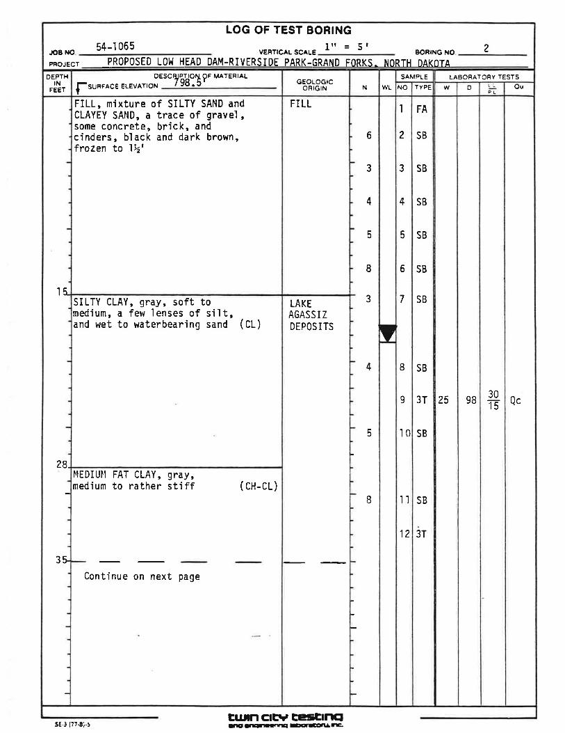
{-sunrace ELEvArtoN ?ö'd:T9' MATERIALOESC
FILL, mixture of SILTY SAND andCLAYEY SAND, a trace of gravel,some concrete, brick, andcinders, black and dark brown,frozen to 1Þz'
SILTY CLAY, 9Fây, soft tomedium, a fevJ lenses of siìt,and wet to waterbearing sand (CL)
l4EDIUll FAT CLAY, 9FdV,medium to rather stiff
Continue on next page
( cH-cL)
pFoJEcr PR0P0SED L0lrl HEAD DAM-RMRSIDE PARK-GRAND FORKS. NORTH DAK0TAVERTICAL SC^LE54-'1065 2BORING NO
LOG OF TEST BORING
JOB NO ltt = 5r
OEPTHIN
FEET
3t
l5-
28.
EUTN Cl¡Tt, EESÈlrllE¡sE-3 (77-8).5 rrÉ --!rr'lÌ¡ aEErlEÉlI r-.
OuLLPL
80E
37T
o
o4Ï
#10
70
1
LAEOFATORY TESTSW
25
51
22
TYPE
3T
SB
SB
SB
SB
SB
SB
SB
SAMPLENO
l3
15
l6
17
18
l9
20
4l
WLN
-12
'10
5
5
7
7
IGEOLOGIC
ORIGIN
LAKEAGASS I ZDEPOS ITS( Cont)
LAKEt.lASHEDTI LL,LAKEAGASS I ZDEPOS ITS
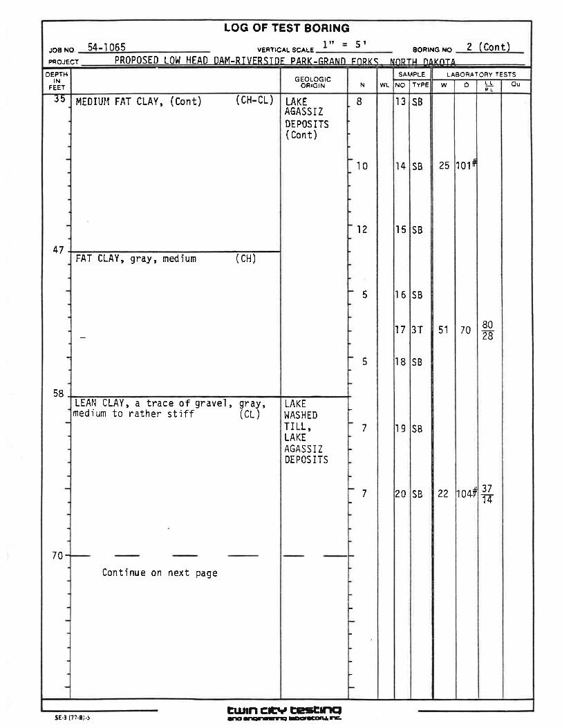
MEDIUII FAT CLAY' (Cont) (CH-CL)
FAT CLAY, 9rây, medium (CH)
LEAN CLAY, a trace of gravel r gFô!,medjum to rather stiff (CL)
Continue on next page
OEPTHIN
FEEf
PRoPoSED L0tl HEAD DAM-RTVFRSTnF pARK-fìÞANn FnÞkç NnDTLt n^rnr,l5r54-'t065 lrt 2 (Cont)
LOG OF TEST BORINGBORING NO.
PROJECT
JOB NO vERlrcAL scALE
47.
58_
70-
J5
Eul¡n cñrv EcsEmclrrE' -rgrrtll-¡ ¡EõlcAlll r-sE.3 (77.8;.t
OuLLPLD
104
LABORATORY TESTSw
22
TYPE
SB
SB
SB
SB
SB
SB
SB
SAMPLENO.
21
23
27
2
2
2
2
WLN
0
I
8
I
7
8
l0
10
I
EOOR
LOG CIGIN
G
LAKEt.lASHEDTI LL,LAKEAGASS I ZDEPOS I TS( Cont)
AGASS I ZDEPOS ITS
OESCRIPTION OF MATEHIAL
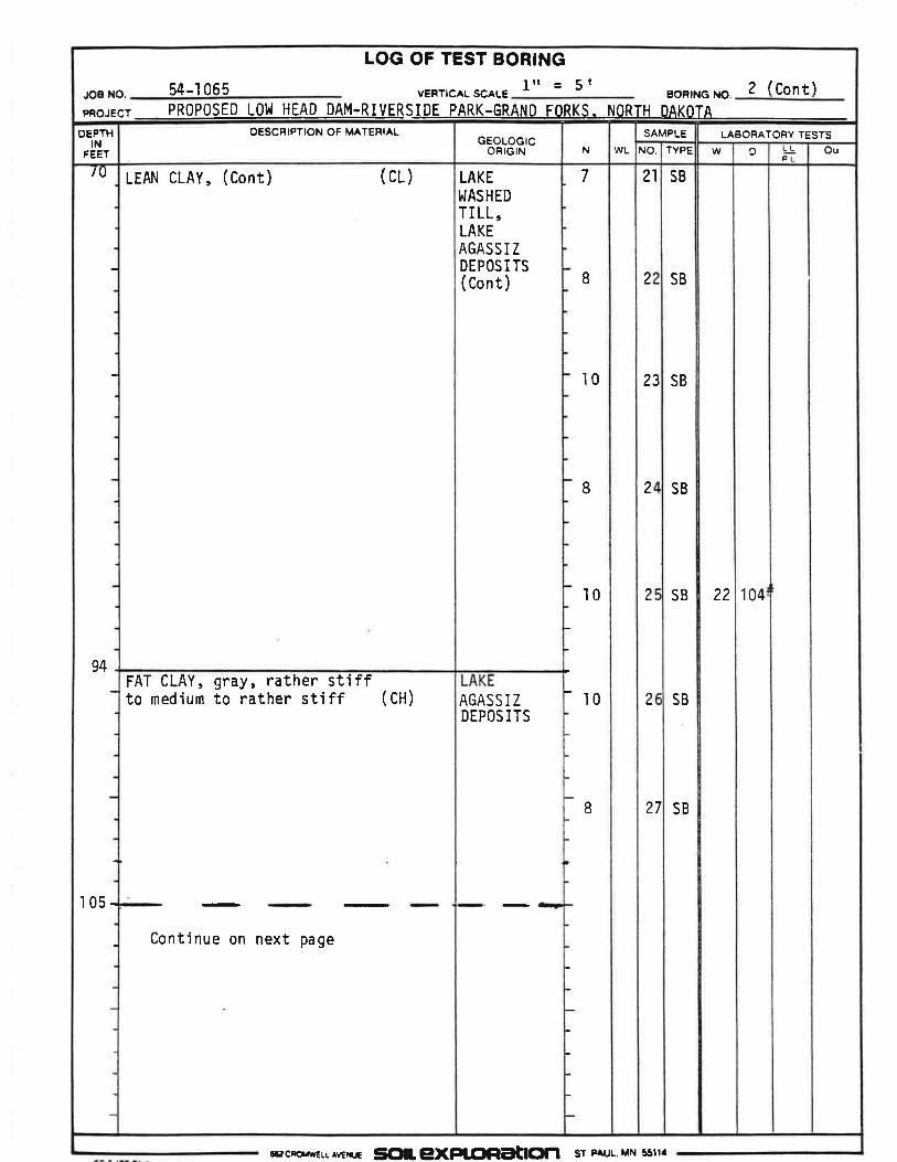
LEAN CLAY, (Cont) (cL)
FAT CLAY, 9rô.y, rather stiffto medium to rather stiff (CH)
Continue on next page
DEPTHIN
FEET
pFoJEcr PROPOSED LOlrJ HEAD DAM-RMRSIDE PARK-GRAND FORKS. NORTH DAKOTA
2 (Cont)BORING NO.VERT¡CAL SCALE54-'t065JOB NO.
LOG OF TEST BORINGlrt = 5t
105-
IU
94
Irac¡o'rÉLr^vr*re SCIILg}(PLC¡FtaðClf| sr P UuMN sstt.
OuLL.PLo
126i¡
LABORATORY IESTS
w
21
TYPE
SB
SB
SB
SB
SAMPLE
NO
2B
29
30
3l
WL
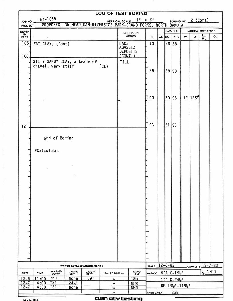
4 :00I 2-6-83STAFIl
@
COMPLEIE
MErHoo 6FA 0-lgtr'4DC O-24r'Dl4 I 9!6 r -l'l 92 |
N
55
-ì
3I
00
98
18tr<lNI'IRNIIR
WATENLEVEL
GEOLOGICORIGIN
LAKEAGASS I ZDEPOSITSIc0NT- ITI LL
BAILED OEPTHS
lotolo
CAVE-INoEPTH
I g'None24ulNone
CASINGOEPTH
SAMPLEDOEPTH
21 |
121'121',
ftrrE
ll:004:004:30
FAT CLAY, (Cont)
End of Boring
#Cal cul ated
SILTY SANDY CLAY, a trace ofgravel, very stiff (cL)
I
JoBNo 54-1065 vERrrc^LscALE ltt = 5 |
PR.JE.TPRoPoSEDf .o_MEÃ,D_o-ÃM-RIVERSIDEPARK.GRAffi_SJ,IORTHõiläiÀ.2 (Cont)
RINGLOG OF TEST BO
DEPTHIN
FEEI
105
108.
121 -
CREW CHIEF
TATER LEVÊL IE SUREXEXÎS
DATE
lo
sE.2 (77-8ì .5 Eurn ctFt ÈrsÈrlcl
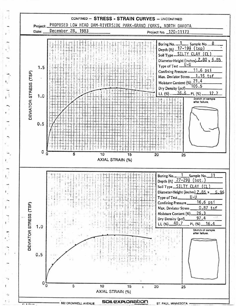
CoNFTNED - STRESS - STRAIN CURVES - utrcorurtrueo
December 28. 1983Date 120-11173Project No,
Proiect: DAKOTAPARK.GRAND FORKS. NORTHPROPOSED LOt^l HEAD DAM-RIVERSIDE
1.5tlU'F.t)Ør¡JÉ.l-v)fEoF5tUo
1.0
0.5
0 0 5 10 15AXTAL STRATN (o/o)
20 25
sl€tch ol sampl€afler lailure.
Boring No. 1 Sample No. B
Depth (ft) 17-19* ( too Isoitrype SILTY CLAY (CL)
(inches)-L80x 5.85U-U
21.405.5
?Á6LL(yù
Diameter-HeightType ofTest
11.6 osiConfining Pressure1.15 tqfMax. Deviator Stress
Moisture ContentDry Density
PL (V") 12 -7!-l
I
I
,l :lI
-+-J
t-Ft::'-:
=
---.1
-l
¡I
+ïtl
If
II
I
rlrI -.r.rl¡
I
I
I
II
!-t-1
i
I
I
l
t'1 ,j l¡i'''l'-l
Ijlli1l iI r-1 :
L I l.i
l,t,lilll¡rltr:
',ii
r-l iirll;lil!'ìirl.¡
lrØFoØt¡JfEØfroFulo
1.0
0 0 5 10 15AX|AL STBATN (%)
20 25
Sketch ol sampl€ette¡ lallure.
1 sttple No. 1127-29+ (bot. )
Diameter-Height (inches)-fu!f, x -L96
Dry Density (pcfl 97.4 '
LL Øl 40 .7 PL (%)
SILTY CI AY ICI ISoilType
Moisture Content
16 _4
lo/^l 26 -?
lt-ilType ofTest16.6 psiConfining Pressure0-R7 fcfMax. Deviator Stress
Boring No.Depth (ft)
iI
J
I'1
I
I-.t
I
-t.l
II
,J
-1
-1'+
I
J
I
i.l_t
I
I¡
_a.-¡
I
,,¡,i.iL l.,l
'l'll itt;, .:.r
1..ll
ir'-¡-iiíl-ir. I
i i -i'"!iii,iiii...r . ! -:
.: -. l-l,'t.i.
lr;lilr Irilirlii'"t ;
'l;'
i :. ì -[-1liriir I .¡-.1il,.ir-lll,li.i l.;'ilrl,
0.5
662 CROMWELL AVENUE sc¡rt exPloRatron ST. PAUL. MINNE9OTJ
lr{ :.
i:t,¡.I
{'.
-,l.r*t
llt;Il,
r't
It.ì
t_
rtl(-lii
Ë.II
l
I
I
l!U)bu)ØulfEFØGo5IUo
0 5 10 15AXIAL STRAIN (o/o)
Sketch ol sampleetler lsilure.
Boring No.-Sample No.-Depth (ft)Soil TypeDiameter-Height (inches)- x
-Type ofTestConfining PressureMa¡<. Deviaùor StressMoisture Content (%)
Dry Density (pcf) - "LL (%) PL(%')
''i-il:i ¡
J
I
f.I
_t
I
l
l¡:-t't_
'i-1
,.i
t
i
{
t
20 25
l!rnbØU)UJccl--U)fEoF[rJo
1.0
0.5
0 0 5 10 15AXIAL STRAIN (o/o)
20 25
Skelch ol sampl€afler lailure.
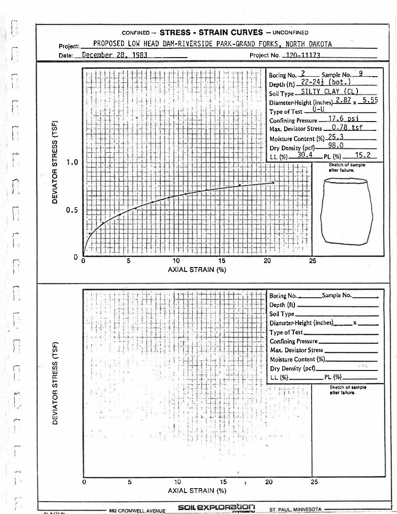
2 Sample No. 922-24+ (bot. )
(incnes)-Z'87.x 5'55U-U
Confining Pressure 17 ' 6 Ps'iMax. Deviator Stress 0 .78 tsf
LL wl 30 -4 PL wl 16 -2
sIt TY Ct AY (Cr )
?q7Moisture Content (%)
Dry Density
Diameter-HeightType ofTest
Boring No.Depth (ft)SoilType
¡
-tt.!l'+-{.++
-l_1.-
I+++
.J. I
++
-LI
++r
+t.-t --+--f
i
I
II
l
I
I
j-i 'r-i'
I
II
:
III
.¡
i--lr1.l l1i"i
lllFI
I
t.
I
II
f
coNFTNED - STRESS - STRAIN CURVES - uxco¡rn¡¡eoPROPOSED LOt^l HEAD DAM.RIVERSIDE PARK-GRAND FORKS, NORTH DAKOTA
12î-1117"Pro¡ect No,Project:oate: December 28. 1983
A662 CROMWELL


![Grand Forks herald (Grand Forks, N.D.). 1918-04-30 [p ]. · 2017-12-16 · East' Grand Forks Commit-; • tc^ Ai^nounces Names;• . ,,$^Purchasers.- , : V\-. • ;C of in to Sr"l-*](https://img.pdfslide.us/doc/110x75/5ec7a9cc76d4fe3f047ef21f/grand-forks-herald-grand-forks-nd-1918-04-30-p-2017-12-16-east-grand.jpg)
![Grand Forks herald (Grand Forks, N.D.). 1917-12-01 [p ]. · Grand Forks herald (Grand Forks, N.D.). 1917-12-01 [p ]](https://img.pdfslide.us/doc/110x75/5e9b4cea4169af71771cee98/grand-forks-herald-grand-forks-nd-1917-12-01-p-grand-forks-herald-grand.jpg)