Embed Size (px)
Citation preview

Pre-Installation Manual for i-Series Machines v387 February 2015
PRE-INSTALLATION MANUAL FOR i-SERIES MACHINES
February 2015

ii - Pre-Installation Manual for i-Series Machines Pre-Installation Manual for i-Series Machines v387
The information in this document is subject to change without notice and does not represent a commitment on the part of Hurco Companies, Inc. (Hurco). The software described in this document is furnished under the License Agreement to customers. It is against the law to copy the software on any medium except as specifically allowed in the license agreement. The purchaser may make copies of the software for backup purposes.
Hurco Manufacturing Company reserves the right to incorporate any modification or improvements in machines and machine specifications which it considers necessary, and does not assume any obligation to make any said changes in machines or equipment previously sold.
Hurco products and services are subject to Hurco’s then current prices, terms, and conditions, which are subject to change without notice.
© 2015 Hurco Companies, Inc. All rights reserved.
Patents:U.S. Patents B14,477,754; 5,453,933; Canadian Patent 1,102,434; Japanese Patents 1,649,006 and 1,375,124; other Patents pending.
Hurco, Max, Ultimax, and WinMax are Registered Trademarks of Hurco Companies, Inc.
AutoCAD, Autodesk, and DXF are registered trademarks of Autodesk, Inc.
MS-DOS, Microsoft, and Windows are registered trademarks of Microsoft Corporation.
Many of the designations used by manufacturers and sellers to distinguish their products are claimed as trademarks. Hurco has listed here all trademarks of which it is aware. For more information about Hurco products and services, contact:
Hurco Companies, Inc. One Technology WayP.O. Box 68180Indianapolis, IN 46268-0180
For Hurco subsidiary contact information, go to Hurco’s Web site:www.hurco.com
Pre-Installation Manual for i-Series Machines v387 Installation Checklist — iii
INSTALLATION CHECKLIST
Prepare the site. . . . . . . . . . . . . . . . . . . . . . . . . . . . . . . . . . . . . . . . . . . . 1 - 2 Ensure the foundation and floor are capable of supporting the machine’s weight. 1 - 3 Ensure there is a clear route from the loading dock to the machine location. . 1 - 4 Ensure there is adequate space for machine door clearances. . . . . . . . . . . . 1 - 4 Ensure there is appropriate power availability and the
voltage requirements are met. . . . . . . . . . . . . . . . . . . . . . . . . . . . . . . . . 1 - 5 Ensure adequate service fusing is available. . . . . . . . . . . . . . . . . . . . . . . . . 1 - 6 Ensure transformer requirements are met. . . . . . . . . . . . . . . . . . . . . . . . . 1 - 7 Ensure proper grounding of machine. . . . . . . . . . . . . . . . . . . . . . . . . . . . . 1 - 7 Ensure compressed air is available. . . . . . . . . . . . . . . . . . . . . . . . . . . . . . 1 - 8 Ensure operating temperature requirements are met. . . . . . . . . . . . . . . . . . 1 - 8 Inspect the machine for damage. . . . . . . . . . . . . . . . . . . . . . . . . . . . . . . . 2 - 2 Ensure an appropriate forklift or crane is available to lift the machine. . . . . . 2 - 3 Review the pre-installation requirements. . . . . . . . . . . . . . . . . . . . . . . . . . 3 - 1 Schedule an appointment for a Hurco-certified Service Engineer
to prepare the machine for start-up after power is connected by a Certified Electrician. . . . . . . . . . . . . . . . . . . . . . . . . . . . . . . . . . . . . 3 - 2
Attend a Hurco programming training class for machine operators. . . . . . . . 3 - 3

iv - Installation Checklist Pre-Installation Manual for i-Series Machines v387

Pre-Installation Manual for i-Series Machines v387 Documentation Conventions — v
DOCUMENTATION CONVENTIONS
This documentation uses several conventions to explain the safety features and emphasize key concepts. These conventions are described in this section.
Icons
This manual may contain the following icons:
Caution/Warning
Important
Troubleshooting
Hints and Tricks
Where can we go from here?
The operator may be injured and the machine severely damaged if the described procedure is not followed.
Ensures proper operation of the machine and control.
? Steps that can be taken to solve potential problems.
Useful suggestions that show creative uses of the WinMax features.
Lists several possible options the operator can take.

vi - Documentation Conventions Pre-Installation Manual for i-Series Machines v387

Pre-Installation Manual for i-Series Machines v387 Table of Contents -vii
TABLE OF CONTENTS
Pre-Installation Manual for i-Series Machines
Installation Checklist . . . . . . . . . . . . . . . . . . . . . . . . . . . . . . . . . . . . . . . . . . iii
Documentation Conventions . . . . . . . . . . . . . . . . . . . . . . . . . . . . . . . . . . . . . vIcons . . . . . . . . . . . . . . . . . . . . . . . . . . . . . . . . . . . . . . . . . . . . . . . . . . v
Site Preparation . . . . . . . . . . . . . . . . . . . . . . . . . . . . . . . . . . . . . . . . . . . . .1 - 1Machine Overview . . . . . . . . . . . . . . . . . . . . . . . . . . . . . . . . . . . . . . . . .1 - 1Bearbeitungszentrum mit WinMax-SteuerungPreparing the Site . . . . . . . . . .1 - 2Foundation Supporting the Machine . . . . . . . . . . . . . . . . . . . . . . . . . . . . .1 - 3
Foundation Guidelines . . . . . . . . . . . . . . . . . . . . . . . . . . . . . . . . . . . .1 - 3Anchoring Machine to Foundation . . . . . . . . . . . . . . . . . . . . . . . . . . . .1 - 3
Machine Dimensions . . . . . . . . . . . . . . . . . . . . . . . . . . . . . . . . . . . . . . . .1 - 4Electrical Service Requirements . . . . . . . . . . . . . . . . . . . . . . . . . . . . . . . .1 - 4
Calculating Service Fusing . . . . . . . . . . . . . . . . . . . . . . . . . . . . . . . . .1 - 6Recommended Isolation Transformer Configuration . . . . . . . . . . . . . . . .1 - 7Grounding Equipment . . . . . . . . . . . . . . . . . . . . . . . . . . . . . . . . . . . .1 - 7
Compressed Air Requirements . . . . . . . . . . . . . . . . . . . . . . . . . . . . . . . . .1 - 8Recommended Operating Temperature . . . . . . . . . . . . . . . . . . . . . . . . . . .1 - 8Tool Retention Knobs . . . . . . . . . . . . . . . . . . . . . . . . . . . . . . . . . . . . . . .1 - 9
Machine Arrival . . . . . . . . . . . . . . . . . . . . . . . . . . . . . . . . . . . . . . . . . . . . . .2 - 1Inspecting for Damage . . . . . . . . . . . . . . . . . . . . . . . . . . . . . . . . . . . . . .2 - 2Moving the Machine into Final Position . . . . . . . . . . . . . . . . . . . . . . . . . . .2 - 3
Machine Lifting Requirements . . . . . . . . . . . . . . . . . . . . . . . . . . . . . . .2 - 3Removing Auxiliary Equipment . . . . . . . . . . . . . . . . . . . . . . . . . . . . . .2 - 3Lowering the Machine onto its Foundation . . . . . . . . . . . . . . . . . . . . . .2 - 6
Start-up Preparation . . . . . . . . . . . . . . . . . . . . . . . . . . . . . . . . . . . . . . . . . .3 - 1Pre-Installation Requirements . . . . . . . . . . . . . . . . . . . . . . . . . . . . . . . . .3 - 1Other Materials . . . . . . . . . . . . . . . . . . . . . . . . . . . . . . . . . . . . . . . . . . .3 - 2Service Visit . . . . . . . . . . . . . . . . . . . . . . . . . . . . . . . . . . . . . . . . . . . . . .3 - 2Programming Training . . . . . . . . . . . . . . . . . . . . . . . . . . . . . . . . . . . . . . .3 - 3
Release Notes . . . . . . . . . . . . . . . . . . . . . . . . . . . . . . . . . . . . . . . . . . . . . . . I
Index . . . . . . . . . . . . . . . . . . . . . . . . . . . . . . . . . . . . . . . . . . . . . . . . . . . . . I

viii - Table of Contents Pre-Installation Manual for i-Series Machines v387

Pre-Installation Manual for i-Series Machines v387 Site Preparation 1-1
SITE PREPARATION
This manual provides instructions for tasks that should be completed prior to the machine installation.
Machine Overview
The pictures below identify some of the easily recognized components of machines. The location of some components may differ on other models.
Figure 1–1. Turning Center with Max Console
Figure 1–2. Machining Center with dual-screen console
1. Max Console2. Turret3. Conveyor option4. Coolant Drip Tray5. Enclosure Door6. Spindle7. Tailstock/Chuck Gauge
options8. Tailstock/Chuck
Footswitch options
1. Dual-screen Console2. Machining Table3. Chip Conveyor4. Enclosure Doors5. Spindle6. Automatic Tool Changer7. Coolant Gun8. Air Gun
1 - 2 Site Preparation Pre-Installation Manual for i-Series Machines v387
Preparing the Site
Prepare the site.
To avoid problems when the equipment arrives for installation, Hurco recommends that the following items be reviewed to ensure that the machine will be ready for the Hurco Service Engineer to install the machine.
Please refer to the model-specific Specification Sheets for weight and dimension specifications for each model.
Review the following:
• Capacity of the floor to support machine weight.
• Capacity of forklift or crane to lift the machine and accessory skids.
• Overhead and door clearances to allow the machine to enter building and machine location.
• Plant obstructions on the way to machine location.
• Code requirements for utility services.
• Proximity of compressed air and proper electrical service.
• Space to allow efficient operation, considering full axes travel and future servicing access requirements.
• Use of internal personnel for management of installation.

Pre-Installation Manual for i-Series Machines v387 Site Preparation 1-3
Foundation Supporting the Machine
Ensure the foundation and floor are capable of supporting the machine’s weight.
The foundation must be able to support the weight of the machine and should be constructed of continuous concrete (reinforced is best). The thickness and consistency of the concrete must be compatible with industry standards for supporting machine weight. Actual requirements will depend upon the physical properties of underlying soil. A local civil engineer must be consulted if soil conditions are questionable.
All Hurco machining and turning centers sit on leveling pads that allow the machine to be leveled.
Foundation Guidelines
The following guidelines are listed on the Foundation/Floor Plan Assembly drawing for each machine:
1. Flatness allowance of the floor level should be within +10 mm (0.39 in).
2. Take precautions so that there are no cracks in the concrete.
3. Leveling bolts are supplied in the shipping box with the machine.
4. Based on the soil conditions, the stiffness of the foundation shall be determined, so that the machine base does not deflect more than 0.013 mm (0.0005) inches to maintain the machine accuracy and performance.
5. The drawing located in the Model-specific Specifications document shows the general arrangement required for the machine foundation. Local masonry contractor and/or civil engineers must be consulted for additional recommendations (e.g. depth, reinforcing steel based on the load bearing characteristics of the soil) to achieve specified performance of the machine.
6. Foundation contractor must paint foundation with a liquid proof paint prior to the installation of the machine to prevent the foundation from absorbing moisture.
Anchoring Machine to Foundation
For improved performance, accuracy, and reliability, Hurco recommends that machines be anchored to the foundation. If a machine is to be anchored, failure to follow the recommended foundation guidelines may void guarantees of quoted machine accuracy.
If a machine is to be anchored, the following requirements must be met:
1. Core drilled hole must be prepared to ensure proper adhesion of grout to the
Please refer to the model-specific specifications document for the machine foundation drawing to provide to the Civil Engineer for location and placement of the leveling pads for the machine, and for machine weight.

1 - 4 Site Preparation Pre-Installation Manual for i-Series Machines v387
foundation concrete.
2. The grout and anchor bolt manufacturers’ recommendations must be followed to ensure full strength of the foundation.
3. After proper cure time, the anchor bolt must be capable of allowing a minimum torque transmission of 271 Nm (200 ft-lb).
Machine Dimensions
Ensure there is a clear route from the loading dock to the machine location.
When moving a machine, be sure to allow adequate space for maneuvering. If door and ceiling clearances appear to be close to approximate machine dimensions, measure the machine first before attempting to move it.
Ensure there is adequate space for machine door clearances.
Allow additional space around the machine for servicing and safe operation. Leave room for removing the coolant tank and the chip conveyor (if equipped).
The Model-specific Specifications document provides these machine dimensions:
• Shipping Dimensions—height, width, length, and weight configuration of the machine and auxiliary equipment as mounted to the skid. Shipping dimensions are measured with the machine on its shipping pallet.
• Operating Dimensions—width and length measurements that must be considered for maintenance and service of the machine, such as opening all enclosure and electrical power cabinet doors and location of auxiliary equipment.
Pre-Installation Manual for i-Series Machines v387 Site Preparation 1-5
Electrical Service Requirements
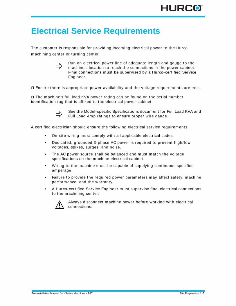
The customer is responsible for providing incoming electrical power to the Hurco machining center or turning center.
Ensure there is appropriate power availability and the voltage requirements are met.
The machine’s full load KVA power rating can be found on the serial number identification tag that is affixed to the electrical power cabinet.
A certified electrician should ensure the following electrical service requirements:
• On-site wiring must comply with all applicable electrical codes.
• Dedicated, grounded 3-phase AC power is required to prevent high/low voltages, spikes, surges, and noise.
• The AC power source shall be balanced and must match the voltage specifications on the machine electrical cabinet.
• Wiring to the machine must be capable of supplying continuous specified amperage.
• Failure to provide the required power parameters may affect safety, machine performance, and the warranty.
• A Hurco-certified Service Engineer must supervise final electrical connections to the machining center.
Run an electrical power line of adequate length and gauge to the machine’s location to reach the connections in the power cabinet. Final connections must be supervised by a Hurco-certified Service Engineer.
See the Model-specific Specifications document for Full Load KVA and Full Load Amp ratings to ensure proper wire gauge.
Always disconnect machine power before working with electrical connections.
1 - 6 Site Preparation Pre-Installation Manual for i-Series Machines v387
Calculating Service Fusing
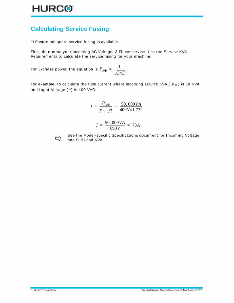
Ensure adequate service fusing is available.
First, determine your incoming AC Voltage, 3 Phase service. Use the Service KVA Requirements to calculate the service fusing for your machine.
For 3-phase power, the equation is .
For example, to calculate the fuse current where incoming service KVA ( ) is 50 KVA and Input Voltage (Ε) is 400 VAC:
See the Model-specific Specifications document for Incoming Voltage and Full Load KVA.
P3ΦI
3xE--------------=
Ρ Φ3
IP3Φ
E 3×----------------- 50 000VA,
400Vx1.732-----------------------------= =
I 50 000VA,693V
-------------------------- 73A= =

Pre-Installation Manual for i-Series Machines v387 Site Preparation 1-7
Recommended Isolation Transformer Configuration
Ensure transformer requirements are met.
If a transformer is required and the machine was not equipped with one, the customer is responsible for providing a transformer. The transformer must meet Hurco machine-operating voltage requirements. Hurco recommends the Wye configuration (4) on the transformer secondary that feeds power to the machine. It is the customer’s responsibility to have a qualified electrician connect the transformer to the power source.
Figure 1–3. Wye Transformer Configuration
Figure 1–4. Delta Transformer Configuration
Grounding Equipment
Ensure proper grounding of machine.
The electrical and electronic control systems of the machining center are interconnected internally and terminate at a single point ground (SPG) terminal. The SPG provides only one conducting path between the machine and external ground, preventing an unwanted ground loop (ground differential voltage). The SPG is located inside the machine power cabinet.
The SPG must be properly connected to the ground circuit of the AC power source.
The grounding conductor must be sized to conform to all applicable electrical codes. However, Hurco recommends that the size of the neutral conductor (when applicable) be at least the size of the phase (current carrying) conductors.
1 - 8 Site Preparation Pre-Installation Manual for i-Series Machines v387
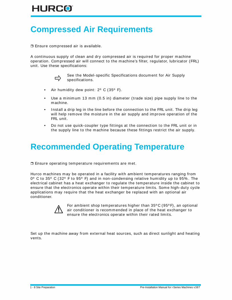
Compressed Air Requirements
Ensure compressed air is available.
A continuous supply of clean and dry compressed air is required for proper machine operation. Compressed air will connect to the machine’s filter, regulator, lubricator (FRL) unit. Use these specifications:
• Air humidity dew point: 2º C (35º F).
• Use a minimum 13 mm (0.5 in) diameter (trade size) pipe supply line to the machine.
• Install a drip leg in the line before the connection to the FRL unit. The drip leg will help remove the moisture in the air supply and improve operation of the FRL unit.
• Do not use quick-coupler type fittings at the connection to the FRL unit or in the supply line to the machine because these fittings restrict the air supply.
Recommended Operating Temperature
Ensure operating temperature requirements are met.
Hurco machines may be operated in a facility with ambient temperatures ranging from 0º C to 35º C (32º F to 95º F) and in non-condensing relative humidity up to 95%. The electrical cabinet has a heat exchanger to regulate the temperature inside the cabinet to ensure that the electronics operate within their temperature limits. Some high-duty cycle applications may require that the heat exchanger be replaced with an optional air conditioner.
Set up the machine away from external heat sources, such as direct sunlight and heating vents.
See the Model-specific Specifications document for Air Supply specifications.
For ambient shop temperatures higher than 35ºC (95ºF), an optional air conditioner is recommended in place of the heat exchanger to ensure the electronics operate within their rated limits.

Pre-Installation Manual for i-Series Machines v387 Site Preparation 1-9
Tool Retention Knobs
Tool retention knobs are required for all Hurco machining centers. The knobs are attached to the top of tool holders and are used by the spindle's clamp mechanism to hold the tool in the spindle. Please refer to the Model-specific Specifications document for more information.

1 - 10 Site Preparation Pre-Installation Manual for i-Series Machines v387
Pre-Installation Manual for i-Series Machines v387 Machine Arrival 2-1
MACHINE ARRIVAL
Upon machine arrival, please complete the following instructions to place the machine at
the installation site (see the appropriate section for detailed information):
1. Inspect the machine upon arrival.
2. Lift machine off the truck or transporter.
3. Move machine near permanent location.
4. Remove auxiliary equipment from pallet.
5. Lift the machine from the pallet.
6. Place the machine on the pads.
7. Rough level the machine.
Follow all local regulations for safe handling of machinery.
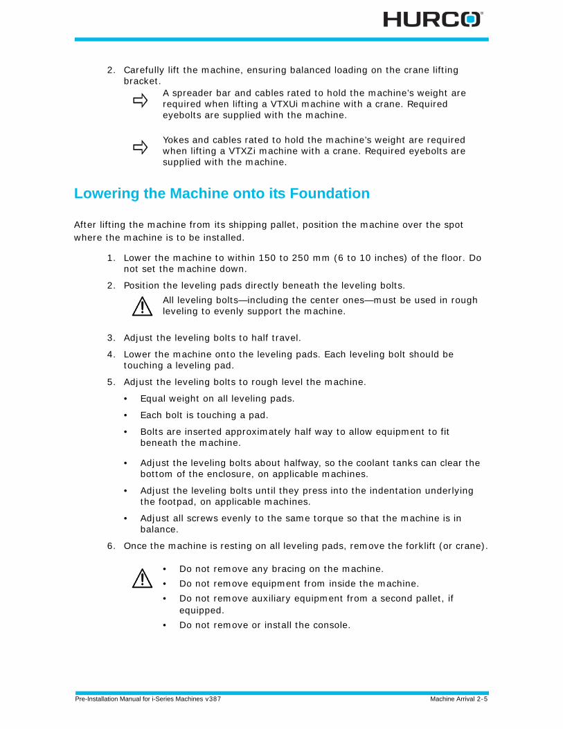
• Do not remove any bracing on the machine.• Do not remove equipment from inside the machine. • Do not remove auxiliary equipment from a second pallet, if
equipped.• Do not remove or install the console.

2 - 2 Machine Arrival Pre-Installation Manual for i-Series Machines v387
Inspecting for Damage
Inspect the machine for damage.
Hurco recommends that the machine equipment be inspected for shipping damage before unloading and placing machine onto foundation.
• Remove all wrapping around machine to inspect the shock sensor.
• Before unloading the machine from the shipping carrier, check to see if the shock meter sensor is tripped. This sensor is located on the casting in the rear of the machine. The shock meter sensor is a spring-loaded device that will dislodge the springs if the machine experiences a shock that exceeds 2g.
Figure 2–1. Shock Meter Sensor—intact (photo on left) and dislodged (photo on right)
• Examine the machine for structural damage.
• Note any shipping damage to the machine on the shipper’s bill of lading. It is the customer’s responsibility to file a damage claim.
• Photograph any equipment damage for your records.
Any damage that occurs during lifting machine off of shipping pallet or placing into position is the responsibility of the customer or the customer’s rigging agent.
If the sensor springs are dislodged, inspect the machine carefully for damage, including all castings.
Hurco-certified Service personnel can help determine the cost of repairing any damages that occurred during shipment, or during or after placement of machine onto its foundation.
Pre-Installation Manual for i-Series Machines v387 Machine Arrival 2-3
Moving the Machine into Final Position
Hurco recommends that the customer review this section to determine if there is proper capacity and ability to lift and place the machine into the location. If not, then a rigging agency should be contacted.
Machine on shipping pallet with auxiliary equipment may be moved near the final position before it is removed from shipping pallet.
Machine Lifting Requirements
Ensure an appropriate forklift or crane is available to lift the machine.
Be sure the crane or forklift is sized properly to lift the machine’s shipping weight. The machine’s shipping weight is defined as the machine on the shipping pallet with the auxiliary equipment still on the pallet.
Move the machine on its shipping pallet to a location next to the final installation site. Set the machine and pallet down, allowing enough space around the machine to later lift the machine off of the shipping pallet. Machine should be removed from the shipping pallet by using a crane or forklift. Be sure the crane or forklift is sized properly to lift the machine off of the shipping pallet.
Removing Auxiliary Equipment
It is recommended to remove auxiliary equipment from the shipping pallet after moving machine on shipping pallet near permanent installation site.
1. Unpack the equipment:
a. Remove the outer covering and all boxes attached to the pallet.b. Remove all packaged items (conveyors, tanks, chillers) from the shipping
pallet.
2. Verify all equipment has arrived and is unloaded.
3. Inspect machine for damage.
4. Remove the nuts and washers that attach the machine to the shipping pallet.
Ensure door clearances are sufficient for the machine to be moved through. Refer to the Model-specific Specifications document for machine dimensions.
Ensure the lifting brackets and crane/forklift capacity are sufficient to hold the machine’s weight. Refer to the Model-specific Specifications document for machine weight.
2 - 4 Machine Arrival Pre-Installation Manual for i-Series Machines v387
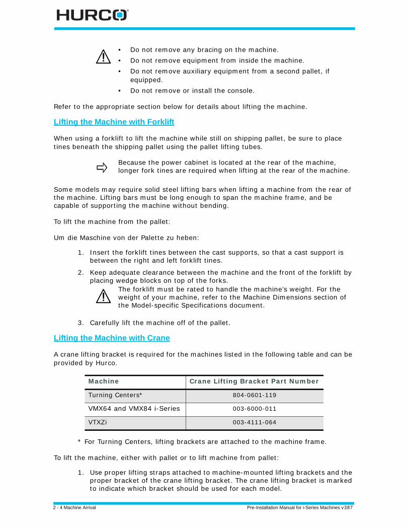
Refer to the appropriate section below for details about lifting the machine.
Lifting the Machine with Forklift
When using a forklift to lift the machine while still on shipping pallet, be sure to place tines beneath the shipping pallet using the pallet lifting tubes.
Some models may require solid steel lifting bars when lifting a machine from the rear of the machine. Lifting bars must be long enough to span the machine frame, and be capable of supporting the machine without bending.
To lift the machine from the pallet:
Um die Maschine von der Palette zu heben:
1. Insert the forklift tines between the cast supports, so that a cast support is between the right and left forklift tines.
2. Keep adequate clearance between the machine and the front of the forklift by placing wedge blocks on top of the forks.
3. Carefully lift the machine off of the pallet.
Lifting the Machine with Crane
A crane lifting bracket is required for the machines listed in the following table and can be provided by Hurco.
* For Turning Centers, lifting brackets are attached to the machine frame.
To lift the machine, either with pallet or to lift machine from pallet:
1. Use proper lifting straps attached to machine-mounted lifting brackets and the proper bracket of the crane lifting bracket. The crane lifting bracket is marked to indicate which bracket should be used for each model.
• Do not remove any bracing on the machine.• Do not remove equipment from inside the machine. • Do not remove auxiliary equipment from a second pallet, if
equipped.• Do not remove or install the console.
Because the power cabinet is located at the rear of the machine, longer fork tines are required when lifting at the rear of the machine.
The forklift must be rated to handle the machine’s weight. For the weight of your machine, refer to the Machine Dimensions section of the Model-specific Specifications document.
Machine Crane Lifting Bracket Part Number
Turning Centers* 804-0601-119
VMX64 and VMX84 i-Series 003-6000-011
VTXZi 003-4111-064
Pre-Installation Manual for i-Series Machines v387 Machine Arrival 2-5
2. Carefully lift the machine, ensuring balanced loading on the crane lifting bracket.
Lowering the Machine onto its Foundation
After lifting the machine from its shipping pallet, position the machine over the spot where the machine is to be installed.
1. Lower the machine to within 150 to 250 mm (6 to 10 inches) of the floor. Do not set the machine down.
2. Position the leveling pads directly beneath the leveling bolts.
3. Adjust the leveling bolts to half travel.
4. Lower the machine onto the leveling pads. Each leveling bolt should be touching a leveling pad.
5. Adjust the leveling bolts to rough level the machine.
• Equal weight on all leveling pads.
• Each bolt is touching a pad.
• Bolts are inserted approximately half way to allow equipment to fit beneath the machine.
• Adjust the leveling bolts about halfway, so the coolant tanks can clear the bottom of the enclosure, on applicable machines.
• Adjust the leveling bolts until they press into the indentation underlying the footpad, on applicable machines.
• Adjust all screws evenly to the same torque so that the machine is in balance.
6. Once the machine is resting on all leveling pads, remove the forklift (or crane).
A spreader bar and cables rated to hold the machine’s weight are required when lifting a VTXUi machine with a crane. Required eyebolts are supplied with the machine.
Yokes and cables rated to hold the machine’s weight are required when lifting a VTXZi machine with a crane. Required eyebolts are supplied with the machine.
All leveling bolts—including the center ones—must be used in rough leveling to evenly support the machine.
• Do not remove any bracing on the machine.• Do not remove equipment from inside the machine. • Do not remove auxiliary equipment from a second pallet, if
equipped.• Do not remove or install the console.

2 - 6 Machine Arrival Pre-Installation Manual for i-Series Machines v387
Pre-Installation Manual for i-Series Machines v387 Start-up Preparation 3-1
START-UP PREPARATION
This chapter contains information about preparing for machine start-up.
Pre-Installation Requirements Review the pre-installation requirements.
Before your full service distributor or Hurco customer service department arrives to install the machine, complete the following requirements:
• All machine equipment is located at the final installation site.
• Machine is positioned for installation, on a suitable foundation that will bear its weight.
• Machine is rough-leveled.
• Utilities (air and electricity) have been made available, but are not connected or turned on.
• Flood coolant tank, tubing, chiller, and coolant pump motor are placed near the machine base.
• Acquire tool retention knobs (Machining Centers). Please refer to the Model-specific Specifications document for details.
• VERY IMPORTANT! Lubrication and fluids are available:
A Hurco-certified Service Engineer will visit your site and prepare the machine for start-up.
Turning Centers Component Available Lubrication Hydraulic Tank fluid, equivalent to ISO. VG 32 Chuck and Tailstock grease for plug points Turret oil, equivalent to ISO VG-100-150 Way Lube Systems oil, equivalent to Waytac Oil #68
Machining CentersComponent Available Lubrication ATC Components and Drives grease, equivalent to Amolith Grease #2 EP Air Line Lubes and Spindle Oil Coolers oil, equivalent to American Ind. Oil #32 Way Lube Systems and Spindle Taper oil, equivalent to Waytac Oil #68 Air/Oil Unit for Tool Release Cylinder oil, equivalent to Teresso 32
It is the customer’s responsibility to provide tooling, coolant, and appropriate lubrication and hydraulic fluid.
3 - 2 Start-up Preparation Pre-Installation Manual for i-Series Machines v387
Other Materials
Please have these materials on hand when the Hurco-certified Service Engineer arrives so that the machine can be fully tested for commissioning.
For Machining Centers:
• Tool holders
• Retention knobs
• Material for test cut
• Coolant mixture
For Turning Centers:
• Tooling
• Boring Bars
• Inserts
• Additional Chuck Jaws
• Collets for the optional collet chuck, if applicable
• Spindle Liners for doing bar work
• Straight Shank Collet Chucks for small drills
• Tension/Compression Tap Holder
• Additional boring sleeves if needed
• Material for test cut
• Coolant mixture
Pre-Installation Manual for i-Series Machines v387 Start-up Preparation 3-3
Service Visit Schedule an appointment for a Hurco-certified Service Engineer to prepare the machine for start-up after power is connected by a Certified Electrician.
A Certified Electrician needs to provide power to the machine prior to the service engineer’s arrival. The Hurco-certified Service Engineer performs these tasks:
1. Checks electrical service to the Main Disconnect switch on the machine.
2. Installs the control console.
3. Measures voltages in the electrical cabinet and the control enclosure.
4. Installs the flood coolant tank and coolant pump motor.
5. Installs covers and enclosures.
6. Completes the machine level and makes required adjustments.
7. .Checks fans and pumps for proper operation
8. Checks all axes for calibration and correct limit switch operation.
9. Installs and tests all options.
Programming Training Attend a Hurco programming training class for machine operators.
Hurco and full-service distributors offer hands-on training classes to demonstrate the powerful programming capabilities of its controls. Customers will gain knowledge of the console and machine by attending training classes.
For additional information or to register for a training class, contact your local Hurco office or distributor, or go to the Hurco website at www.hurco.com.

3 - 4 Start-up Preparation Pre-Installation Manual for i-Series Machines v387
Pre-Installation Manual for i-Series Machines v387 Release Notes — I
RELEASE NOTES
Pre-installation Manual for i-Series Machines
v387 February 2015Revised by: H. ArleApproved by: D.SkrzypczakUpdate to add Machining Centers. Manual title update to “Pre-Installation Manual for i-Series Machines.”
v385 January 2015Revised by: K. GrossApproved by: D.SkrzypczakInitial release for Turning Centers only.

II - Release Notes Pre-Installation Manual for i-Series Machines v387
Pre-Installation Manual for i-Series Machines v387 Index —I
INDEX
Aair humidity 1 - 8
Cclasses, training 3 - 3control, training 3 - 3coolant
flood tank 2 - 3, 3 - 1pump motor 2 - 3, 3 - 1removing tank 1 - 4
Ddamage, claim 2 - 2dimensions, machine 1 - 4
Eelectrical
codes 1 - 5hookup 1 - 4requirements 1 - 4
transformer 1 - 7equipment
electrical grounding 1 - 7grounding 1 - 7, 1 - 8inspection 2 - 2installation 3 - 1unpacking machine 2 - 3
Ffoundation
construction requirements 1 - 3lowering the machine onto 2 - 6
Gground (SPG) terminal, single point 1 - 7grounding equipment 1 - 7, 1 - 8
Hhumidity
air 1 - 8electrical cabinet 1 - 8
Hurco training 3 - 3
Iicons - vinput voltage 1 - 7inspecting for damage 2 - 2installation
machine 2 - 6, 3 - 1preparing site 1 - 2
isolation transformerrecommended configuration 1 - 7
Lleveling bolts 2 - 6lifting
steel lifting bars 2 - 4lowering the machine onto its foundation
2 - 6
Mmachine
coolant system 1 - 9equipment, unpacking 2 - 3final positioning 2 - 6foundation 1 - 3grounding 1 - 7inspection 2 - 2installation (see installation) 1 - 2leveling bolts 2 - 6recommended humidity and
temperature, operating 1 - 8removing from shipping pallet 2 - 6requirements before service visit 3 - 1start-up 3 - 1transformer 1 - 5, 1 - 7unpacking equipment 2 - 3
meter sensor, shock 2 - 2moving the machine into final position 2 - 3
Ooperating
machine dimensions 1 - 4temperature 1 - 8
Ppoint ground (SPG) terminal, single 1 - 7preparing the installation site 1 - 2
II - Index Pre-Installation Manual for i-Series Machines v387
Rremoving coolant tank 1 - 4requirements
foundation 1 - 3installation site 1 - 2
SSchäden
an neuen MaschinenInspektion 2 - 2
sensor, shock meter 2 - 2shipping
machine dimensions) 1 - 4unpacking equipment 2 - 3
shipping pallet, removing machine 2 - 6shock meter sensor 2 - 2single point ground (SPG) terminal 1 - 7site
foundation 1 - 3preparing for machine 1 - 2preparing the installation 1 - 2
SPG terminal, single point ground 1 - 7start-up
requirements 3 - 1
Ttemperature, operating 1 - 8terminal, single point ground (SPG) 1 - 7tool retention knobs 1 - 9training classes 3 - 3
Uunloading machine from pallet 2 - 6unpacking machine equipment 2 - 3
Vvoltage input 1 - 7
Wweight, machine and supporting foundation
1 - 3WinMax training 3 - 3