Embed Size (px)
Citation preview
Doctor: __________________________________________________Address: __________________________________________________Phone#: __________________________________________________Dealer: __________________________________________________Dealer Address: __________________________________________________
A l l i n s t a l l a t i o n s m u s t c o n f o r m t o l o c a l c o d e s .
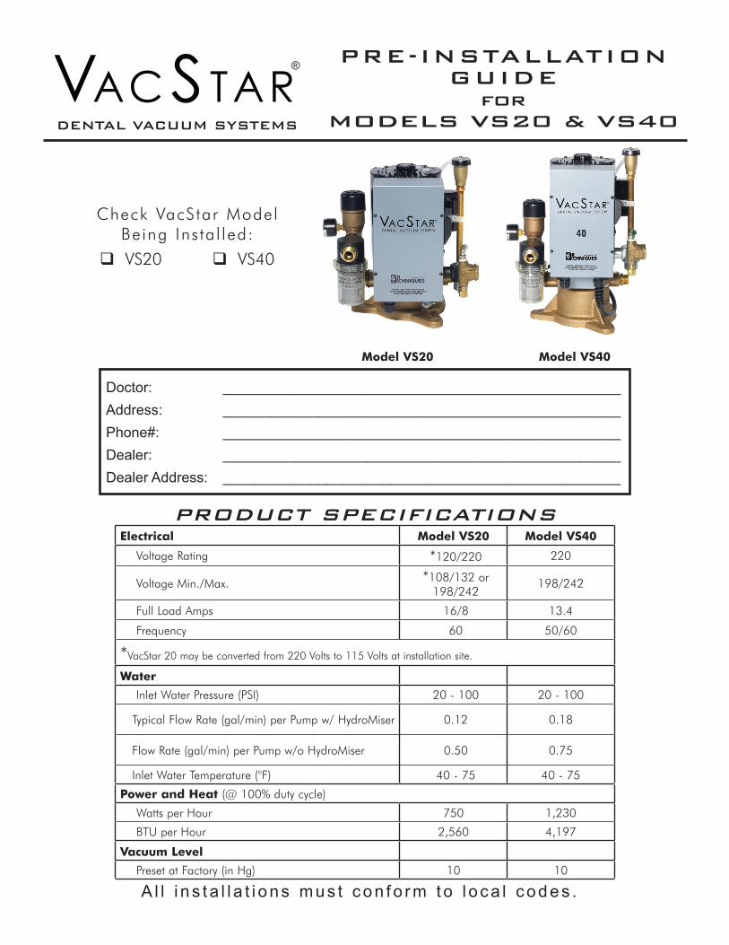
PRE-INSTALLATION GUIDE
for MODELS VS20 & VS40
Model VS20 Model VS40
Check VacStar Model Being Ins ta l led:
VS20 VS40
DENTAL VACUUM SYSTEMS
PRODUCT SPECIFICATIONSElectrical Model VS20 Model VS40
Voltage Rating *120/220 220
Voltage Min./Max. *108/132 or 198/242
198/242
Full Load Amps 16/8 13.4
Frequency 60 50/60
*VacStar 20 may be converted from 220 Volts to 115 Volts at installation site.
Water
Inlet Water Pressure (PSI) 20 - 100 20 - 100
Typical Flow Rate (gal/min) per Pump w/ HydroMiser 0.12 0.18
Flow Rate (gal/min) per Pump w/o HydroMiser 0.50 0.75
Inlet Water Temperature (°F) 40 - 75 40 - 75
Power and Heat (@ 100% duty cycle)
Watts per Hour 750 1,230
BTU per Hour 2,560 4,197
Vacuum Level
Preset at Factory (in Hg) 10 10
Page 2
MEDICAL ELECTRICAL EQUIPMENT
WITH RESPECT TO ELECTRICAL SHOCK, FIRE, MECHANICALAND OTHER SPECIFIED HAZARDS ONLY
IN ACCORDANCE WITH UL-60601-1, CAN/CSA C22.2 NO.601.1 66CA
CLASSIFIED
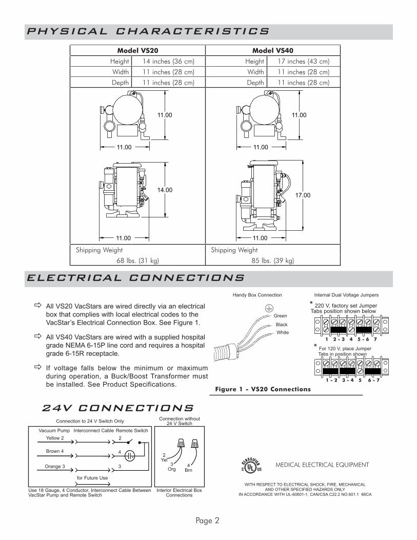
All VS20 VacStars are wired directly via an electrical box that complies with local electrical codes to the VacStar’s Electrical Connection Box. See Figure 1.
All VS40 VacStars are wired with a supplied hospital grade NEMA 6-15P line cord and requires a hospital grade 6-15R receptacle.
If voltage falls below the minimum or maximum during operation, a Buck/Boost Transformer must be installed. See Product Specifications.
Figure 1 - VS20 Connections
ELECTRICAL CONNECTIONS
PHYSICAL CHARACTERISTICS
Use 18 Gauge, 4 Conductor, Interconnect Cable Between VacStar Pump and Remote Switch
Interior Electrical Box Connections
Connection to 24 V Switch Only Connection without 24 V Switch
Vacuum PumpYellow 2
Brown 4
Interconnect Cable
Orange 3
Remote Switch2
4
3
for Future Use
2 Yel
4 Brn
3 Org
24V CONNECTIONS
Green
BlackWhite
Handy Box Connection
* For 120 V, place Jumper Tabs in position shown
* 220 V, factory set Jumper Tabs position shown below
1 - 2 3 - 4 5 6 - 7
1 2 - 3 4 5 - 6 7
Internal Dual Voltage Jumpers
Model VS20 Model VS40
Height 14 inches (36 cm) Height 17 inches (43 cm)
Width 11 inches (28 cm) Width 11 inches (28 cm)
Depth 11 inches (28 cm) Depth 11 inches (28 cm)
17.0014.00
11.00 11.00
11.00 11.00
11.00 11.00
17.0014.00
11.00 11.00
11.00 11.00
11.00 11.00
Shipping Weight Shipping Weight
68 lbs. (31 kg) 85 lbs. (39 kg)
Page 3
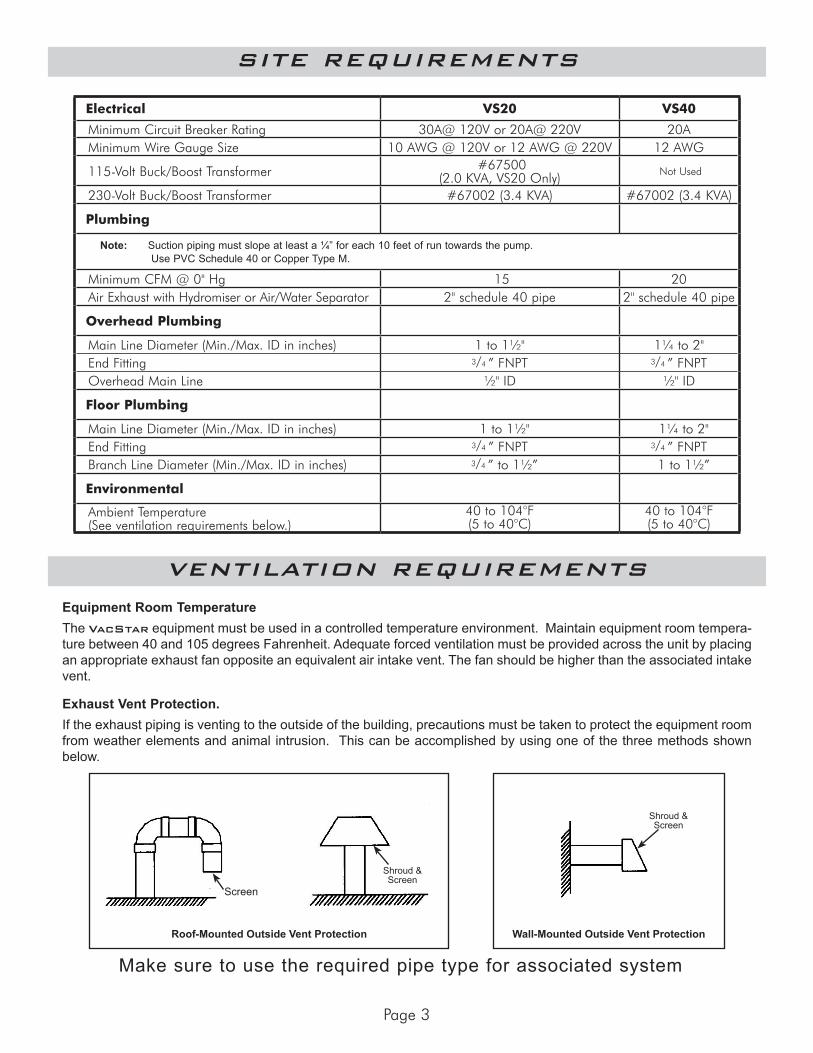
Make sure to use the required pipe type for associated system
SITE REQUIREMENTS
Electrical VS20 VS40
Minimum Circuit Breaker Rating 30A@ 120V or 20A@ 220V 20AMinimum Wire Gauge Size 10 AWG @ 120V or 12 AWG @ 220V 12 AWG
115-Volt Buck/Boost Transformer #67500 (2.0 KVA, VS20 Only) Not Used
230-Volt Buck/Boost Transformer #67002 (3.4 KVA) #67002 (3.4 KVA)
Plumbing
Note: Suction piping must slope at least a ¼” for each 10 feet of run towards the pump. Use PVC Schedule 40 or Copper Type M.
Minimum CFM @ 0" Hg 15 20Air Exhaust with Hydromiser or Air/Water Separator 2" schedule 40 pipe 2" schedule 40 pipe
Overhead Plumbing
Main Line Diameter (Min./Max. ID in inches) 1 to 1½" 1¼ to 2"End Fitting 3/4 ” FNPT 3/4 ” FNPTOverhead Main Line ½" ID ½" ID
Floor Plumbing
Main Line Diameter (Min./Max. ID in inches) 1 to 1½" 1¼ to 2"End Fitting 3/4 ” FNPT 3/4 ” FNPTBranch Line Diameter (Min./Max. ID in inches) 3/4 ” to 1½” 1 to 1½”
Environmental
Ambient Temperature (See ventilation requirements below.)
40 to 104°F (5 to 40°C)
40 to 104°F (5 to 40°C)
Equipment Room TemperatureThe VacStar equipment must be used in a controlled temperature environment. Maintain equipment room tempera-ture between 40 and 105 degrees Fahrenheit. Adequate forced ventilation must be provided across the unit by placing an appropriate exhaust fan opposite an equivalent air intake vent. The fan should be higher than the associated intake vent.
Exhaust Vent Protection.If the exhaust piping is venting to the outside of the building, precautions must be taken to protect the equipment room from weather elements and animal intrusion. This can be accomplished by using one of the three methods shown below.
VENTILATION REQUIREMENTS
Wall-Mounted Outside Vent Protection
Shroud & Screen
Roof-Mounted Outside Vent Protection
Screen
Shroud & Screen
Page 4
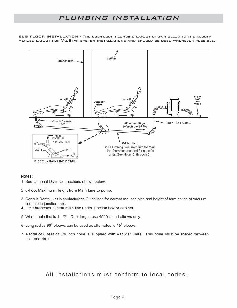
PLUMBING INSTALLATION
Notes:1. See Optional Drain Connections shown below.
2. 8-Foot Maximum Height from Main Line to pump.
3. Consult Dental Unit Manufacturer's Guidelines for correct reduced size and height of termination of vacuum line inside junction box.
4. Limit branches. Orient main line under junction box or cabinet.
5. When main line is 1-1/2" I.D. or larger, use 45° Y's and elbows only.
6. Long radius 90° elbows can be used as alternates to 45° elbows.
7. A total of 8 feet of 3/4 inch hose is supplied with VacStar units. This hose must be shared between inlet and drain.
SUB FLOOR INSTALLATION - The sub-floor plumbing layout shown below is the recom-mended layout for VacStar system installations and should be used whenever possible.
MAIN LINESee Plumbing Requirements for Main
Line Diameters needed for specific units. See Notes 3, through 6.
1/2-Inch Diameter Riser Minumum Slope:
1/4 inch per 10 Feet
Floor SinkSee
Note 1Junction
Box
Riser - See Note 2
RISER to MAIN LINE DETAIL
45°Elbow
45°YTo
Pump
Main Line
From Dental Unit
1/2 Inch Riser
CeilingInterior Wall
A l l i n s t a l l a t i o n s m u s t c o n f o r m t o l o c a l c o d e s .
Page 5
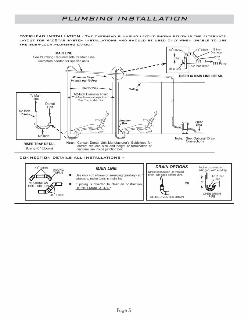
CONNECTION DETAILS ALL INSTALLATIONS -
DRAIN OPTIONS
OR
Use only 45° elbows or sweeping (sanitary) 90° elbows to make turns in main line.
If piping is diverted to clear an obstruction, DO NOT MAKE A TRAP.
MAKING TURNS
45° Elbow
45° Elbow
CLEARING AN OBSTRUCTION
MAIN LINE
OVERHEAD INSTALLATION - The overhead plumbing layout shown below is the alternate layout for VacStar system installations and should be used only when unable to use the sub-floor plumbing layout.
Indirect connection (Air gap) with a p-trap.
OPEN DRAIN PIPE
1-1/2 InchP-Trap
CLOSED VENTED DRAIN
Direct connection to vented drain. No traps before vent.
6”
Note: Consult Dental Unit Manufacturer's Guidelines for correct reduced size and height of termination of vacuum line inside junction box.
Note: See Optional Drain Connections
MAIN LINESee Plumbing Requirements for Main Line
Diameters needed for specific units.
Minumum Slope: 1/4 inch per 10 Feet
Ceiling
Floor Sink
Junction Box
Interior Wall
1/2-Inch Diameter Riser10-Foot Maximum Height from
Riser Trap to Main Line
1/2-Inch Riser
To Main Line
Dental Unit
1/2-Inch
RISER TRAP DETAIL (Using 45° Elbows)
1/2 Inch Riser
RISER to MAIN LINE DETAIL
45°Elbow45°Elbow
45°Y
1/2 Inch Diameter
To STS Pump
1" Min
Main Line
PLUMBING INSTALLATION
Page 6
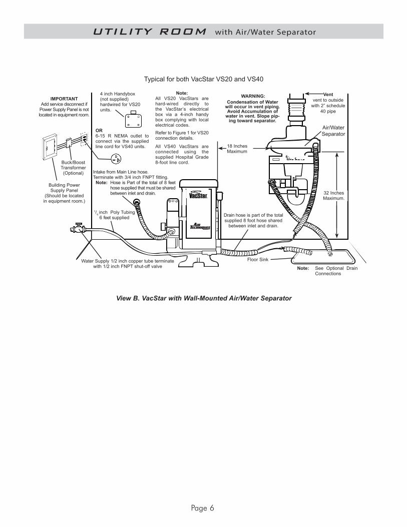
Air/WaterSeparator
Intake from Main Line hose.Terminate with 3/4 inch FNPT fitting.
Note: Hose is Part of the total of 8 feet hose supplied that must be shared between inlet and drain.
Floor Sink
32 InchesMaximum.
18 InchesMaximum
1/4 inch Poly Tubing 6 feet supplied
Ventvent to outside
with 2” schedule 40 pipe
WARNING:Condensation of Water
will occur in vent piping.Avoid Accumulation of
water in vent. Slope pip-ing toward separator.
Note: See Optional Drain Connections
Typical for both VacStar VS20 and VS40
View B. VacStar with Wall-Mounted Air/Water Separator
Building Power Supply Panel
(Should be located in equipment room.)
Buck/Boost Transformer(Optional)
IMPORTANTAdd service disconnect if
Power Supply Panel is not located in equipment room.
Note:All VS20 VacStars are hard-wired directly to the VacStar’s electrical box via a 4-inch handy box complying with local electrical codes.Refer to Figure 1 for VS20 connection details.
All VS40 VacStars are connected using the supplied Hospital Grade 8-foot line cord.
OR6-15 R NEMA outlet to connect via the supplied line cord for VS40 units.
4 inch Handybox (not supplied) hardwired for VS20 units.
UTILITY ROOM with Air/Water Separator
Water Supply 1/2 inch copper tube terminate with 1/2 inch FNPT shut-off valve
Drain hose is part of the total supplied 8 foot hose shared
between inlet and drain.
Page 7
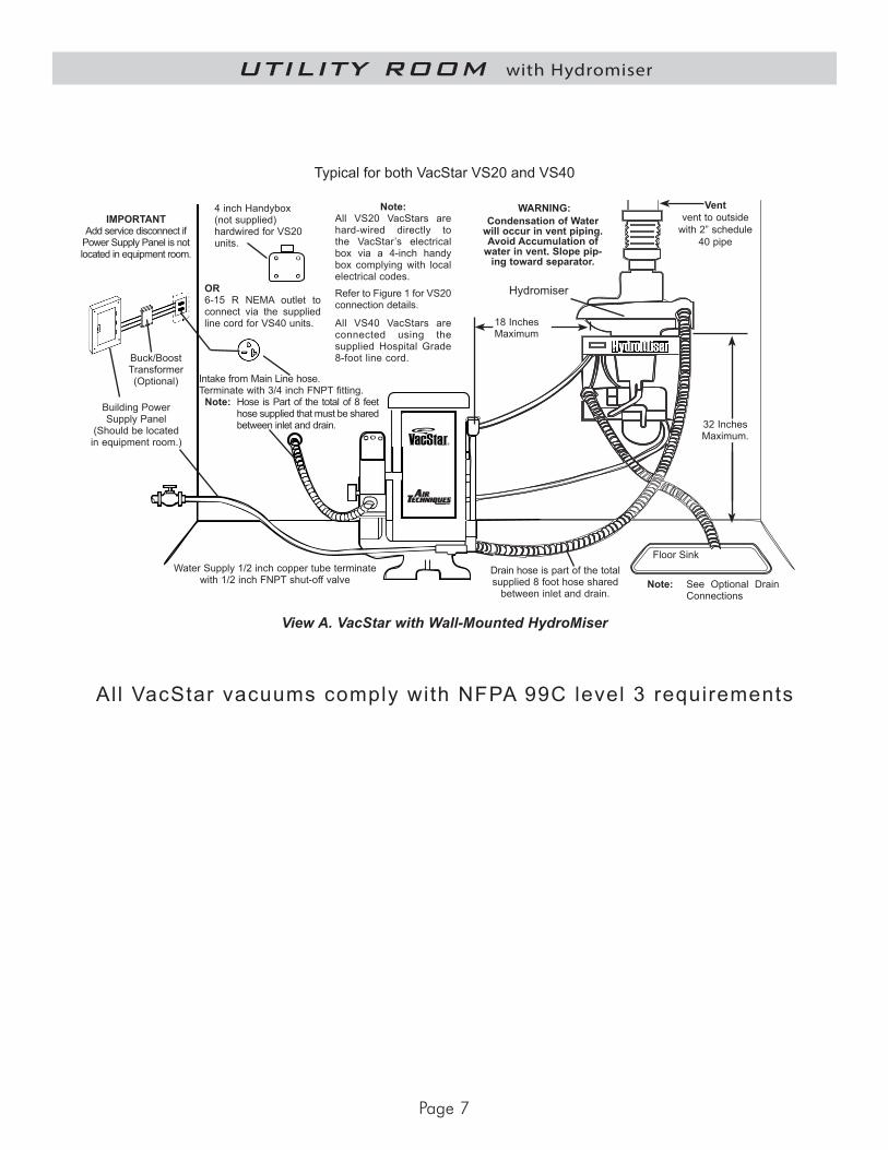
All VacStar vacuums comply with NFPA 99C level 3 requirements
UTILITY ROOM with Hydromiser
Hydromiser
Water Supply 1/2 inch copper tube terminate with 1/2 inch FNPT shut-off valve
Floor Sink
32 InchesMaximum.
18 InchesMaximum
Note: See Optional Drain Connections
Typical for both VacStar VS20 and VS40
View A. VacStar with Wall-Mounted HydroMiser
Intake from Main Line hose.Terminate with 3/4 inch FNPT fitting.
Note: Hose is Part of the total of 8 feet hose supplied that must be shared between inlet and drain.
Ventvent to outside
with 2” schedule 40 pipe
WARNING:Condensation of Water
will occur in vent piping.Avoid Accumulation of
water in vent. Slope pip-ing toward separator.
Building Power Supply Panel
(Should be located in equipment room.)
Buck/Boost Transformer(Optional)
IMPORTANTAdd service disconnect if
Power Supply Panel is not located in equipment room.
Note:All VS20 VacStars are hard-wired directly to the VacStar’s electrical box via a 4-inch handy box complying with local electrical codes.Refer to Figure 1 for VS20 connection details.
All VS40 VacStars are connected using the supplied Hospital Grade 8-foot line cord.
OR6-15 R NEMA outlet to connect via the supplied line cord for VS40 units.
4 inch Handybox (not supplied) hardwired for VS20 units.
Drain hose is part of the total supplied 8 foot hose shared
between inlet and drain.

VacStar and Hydromiser are trademarks of Air Techniques, Inc.© 2008 Air Techniques, Inc. • Part No 55341, Rev. P, December 2017
You can obtain more information about Air Techniques’ products by visiting our web site at www.airtechniques.com
Additional installation information is available on our Authorized Air Techniques Dealer web site at http://dealers.airtechniques.com
Air Techniques Inc.1295 Walt Whitman Road, Melville, NY 11747-3062Website: www.airtechniques.com1-800-AIR-TECH (1-800-247-8324)