Embed Size (px)
Citation preview

PRE-FEASIBILITY REPORT
Of
Captive Thermal Power PlantArasmeta village, Akaltra Tehsil
Janjgir-Champa district, Chhattisgarh
For
INSTALLATION OF 20 MW COAL BASED CAPTIVEPOWER PLANT WITHIN THE EXISTING CEMENT
PLANT COMPLEX
By
M/s. NUVOCO VISTAS CORP. LTD.(formerly Lafarge India Limited)

Table of Contents
1. Executive summary2. Introduction of the project/ Background information3 Project Description.4 Site Analysis5. Planning Brief.
6 Proposed Infrastructure7. Rehabilitation and Resettlement (R & R) Plan.8. Project Schedule & Cost Estimates9. Analysis of Proposal (Final Recommendations).

1.0 EXECUTIVE SUMMARY
M/s. NUVOCO VISTAS CORP. LTD (NUVOCO) is operating ArasmetaCement Plant at Arasmeta village, Akaltra Tehsil of Janjgir-ChampaDistrict in Chhattisgarh State. The plant is located in an area of 82Hectares (Ha). The production capacity of the plant is 1.6 MillionTonnes per Annum (MTPA) of Clinker & 2.24 MTPA of Cement.
M/s. Nuvoco Vistas Corp. Ltd (NUVOCO) entered the Indian market in1999. NUVOCO has four cement plants in India: two plants in thestate of Chattisgarh (Sonadih and Arasmeta). The plant is located atArasmeta village, Akaltra Tehsil of Janjgir-Champa District,Chattisgarh.
The NUVOCO Arasmeta cement plant is of clinkerisation capacity5200 TPD and having two cement grinding mills. Capacity of grindingmills is 135 TPH and 105 TPH. Cement plant was commissioned in1985.
Currently the cement plant electrical energy requirement is being metfrom the Chattisgarh State Power Distribution Company Limited(CSPDCL). Plant has 132kV/6.6kV receiving substation having threesteps down transformer of 12 MVA, 132kV/6.6 kV.
Maximum power requirement of the plant is 24.5 MW whereasaverage power requirement is 21.5 MW. As on date the maximumcontract demand from the grid is 27MVA.
NUVOCO Arasmeta cement plant also has installed 3x 6MW HFObased DG power plant.
In view of the high power tariff & increasing trend in the tariff ofenergy by CSPDCL. NUVOCO is contemplating to have Self Powergeneration to meet bulk power requirement of the cement plant.
NUVOCO proposes to set up a 20 MW Coal based Thermal PowerPlant to meet the power requirement of the existing cement plant.Salient features of the power plant are given below
CLIENT M/s. NUVOCO VISTAS CORP. LTD(formerly Lafarge India Limited)
Location Place : Chhattisgarh – Arasmeta Country : India
Plant Capacity 1 x 20 MW - Thermal Power PlantTechnology Conventional steam cycle operating in
Rankine cycle, consisting of 90 TPHCFBC boiler and 1 no. Turbine 535 deg.C at 110 ata pressure.
Main Fuel Indian Coal / Washery Reject

Type of Coal for design ofboiler
Imported coal or Indian coal or washeryreject coal or combination of abovefuels
Source of water River water from lilagar riverWater RequirementTotal raw waterrequirement
280 m3/day
Annual generation 123.0 mio kwhAnnual auxiliaryconsumption
12.3 mio kwh
Net output 110.7 mio kwhLand Requirement 2.50 HaManpower Requirement 43 persons & 24 contract labourProject ImplementationSchedule
3 months for Power Plant OrderPlacement
22 months from main machineryorder placement to commissioning
The proposed new unit will be located within the existing cement plantcomplex. No additional land or site is required. Keeping in view ofutilizing some of the common existing infrastructure.
Fuel proposed for thermal power plant will be imported coal or Indiancoal or washery reject coal or combination of above fuels.
The power plant is based on air cooled condensate system. The waterrequirement for the proposed CPP plant works out to be approximately280 m3/ day. Water demand is proposed to be met from the presentwater source being received from Lilagar River.
Waste water generated from the power plant will be treated and usedin the cement plant, and the treated effluent will be used fordevelopment/maintenance of the green belt. An effluent disposalpump will be used for this purpose.
The wastewater generated from the power plant will be used fordevelopment/maintenance of the green belt.
Ash generated from the power plant will be consumed in existingcement plant.
There is no wild life sanctuary, national park, eco-sensitive areawithin the 10 km radius of the project site. Kotmi-sunar CrocodilePark is at a distance of 6.4 km in NNE with respect to the site. It isnot a Notified area.
Existing infrastructure include railway siding and well developedroads, storm water drains with adequate storage space for flyash andparking area.
All infrastructure facilities such as education, health facilities andother social facilities are adequate at nearest populated area
Dust collected from air pollution control equipment is 100% recycledin process and Ash generated in power plant will be consumed inexisting cement plant.
NUVOCO has well-defined CSR policy to Carryout social developmentand welfare measures in the surrounding villages. Under CSR activityNUVOCO had carried out community development projects, in thefields of health, education and environmental preservation, in andaround the plant.
The capital cost, for the proposed production enhancement project,works out to Rs 126 crore.

2. INTRODUCTION OF THE PROJECT/ BACKGROUND INFORMATION
(I) IDENTIFICATION OF PROJECT AND PROJECT PROPONENT
NUVOCO entered the Indian market in 1999, through its cementbusiness. NUVOCO currently has 4 cement plants in India. In recentyears, NUVOCO has significantly enlarged its operations across itsthree business divisions - Cement, Aggregates and Concrete. Thecompany has an established presence across all major cities andtowns in India. NUVOCO today is the market leader in the ready-mixconcrete business with around 70 plants. To make advances inbuilding materials, NUVOCO e places the customer at the heart of itsconcerns.
The Group’s expertise in efficient industrial processes generate value,protects the environment, shows respect for societies & cultures andis sparing in its use of natural resources and energy.
Nuvoco Vistas Corp. Ltd. was formed in the year 1999 and it startedoperation in India by acquiring Cement Division of Tata Steel withintegrated cement plant located at Sonadih, Dist.: Raipur, State:Chattisgarh & grinding unit at Jojobera, Dist.: Jamshedpur, State:Jharkhand. Subsequently, in the beginning of the year 2001 it alsoacquired Raymond Cement Plant situated in Dist.: Bilaspur State:Chattisgarh and this plant is now renamed as Arasmeta CementPlant. NUVOCO commissioned a green field project at Distt.Chhittorgarh in Rajasthan in 2013.
Nuvoco Vistas Corp. Ltd. is operating 1.5 MTPA of Fly-Ash Cementgrinding station which is a State-of-the-art cement grinding unitbased on latest and most eco-friendly technology adjacent to ThermalPower Station of Damodar Valley Corporation, Mejia, District BankuraWest Bengal and is committed to grow with the environment. The unitis utilising bulk quantity of Fly –Ash generated by Mejia ThermalPower Station (MTPS) of Damodar Valley Corporation in an eco-friendly manner thus is instrumental in abating the Pollution in theregion.
(ii) BRIEF DESCRIPTION OF NATURE OF THE PROJECT
The proposal is for setting up of 20 MW coal based captive power plantwithin the existing cement plant complex. Power plant is based onCirculating Fluidised Bed Combustion (CFBC) with air cooledcondensate system. Fuel proposed for thermal power plant is importedcoal or Indian coal or washery reject coal or combination of abovefuels. One 90 TPH boiler will be installed to meet steam requirementof the power plant.

(iii) NEED FOR THE PROJECT AND ITS IMPORTANCE TO THECOUNTRY AND OR REGION
Currently the cement plant electrical energy requirement is beingmet from the Chattisgarh State Power Distribution CompanyLimited (CSPDCL). Plant has 132kV/6.6kV receiving substationhaving three step down transformer of 12 MVA, 132kV/6.6 kV.
Maximum power requirement of the plant is 24.5 MW where asaverage power requirement is 21.5 MW. As on date the maximumcontract demand from the grid is27MVA.
NUVOCO VISTAS CORP LTD Arasmeta cement plant also has installed3x 6MW HFO based DG power plant.
SECTION WISE SPECIFIC POWER REQUIREMENTSn Description Capacity Power
Requirement/Pea k Power
Requirement
Unit Value
01 Crushing 1.0 MW Kwh/T 2.002 Raw mill 1
Grinding withtransportationfrom crusherto Raw millhopper
135 TPH 3.1 MW Kwh/T 21.89
03 Raw mill 2Grinding withtransportationfrom crusherto Raw millhopper
220 TPH 3.8 MW Kwh/T 18.6
04 Coal Millgrinding 1
18 TPH 1.0 MW Kwh/T 28.04
05 Coal Millgrinding 2
25TPH 1.0 MW Kwh/T 34.53
06 Pyro(Kiln,cooler, PH)and transport
5200TPD
6.0 MW Kwh/T 27.57
07 ClinkerisationTotal
Kwh/T 66.15
08 Colony 0.5 MW Kwh/T 0.3009 Total
Requirement uptoPyro section
16.4 MW / 66.45
10 Peak Power Requirement including starting Shock load of Large drive17.90 MW11 Cement (PPC) Mill-1-
135Mill-1-3.1 MW Kwh/T 31.0

Mill-2-105
Mill-2-3.5 MW
12 Packing plant Kwh/T 1.85
13 Peak powerrequirementFor CementGrinding
6.6 MW 32.85
14 Specific PowerConsumption
Kwh/T 74.71
15 - PeakPower &
EnergyRequirement
24.5 MW 176.64mioKwh per
annum(320daysofoperation)
In view of the very high power tariff from CSEB, NUVOCO intend tohave own power generation comprising of WHR Power Plant & Captivethermal power plant for meeting major power and energy requirementof the cement plant.
In addition to above CSEB grid connection will be retained for meetingthe peak load requirement/outage of any source consisting of WHRpower plant and coal fired captive power plant.
The objective of the study is to finalize Capacity of the Power Plantbased on the best available option considering reliable and costeffective power generation.
A) POWER COST FROM CSEB GRID
The power tariff by CSEB is fixed in 2015 is with Demand chargesas Rs 350 /KVA per month. The energy charges as per CSEB are asfollows -
• Peak hours ---------------------------- 6.9/kVAh
• Off peak hours ------------------------ 5.4/kVAh
• Normal hours -------------------------- 6.0/kVAh
Based on the analysis of the Power tariff from 2014 to 2016, theaverage increase in the power tariff & demand charges is 7%.
The average Energy charges paid at Aresmeta considering Fixeddemand charges & variable Energy charges is Rs 6.81 /kwh and afterincluding duty same is Rs 7.15 / kWh.
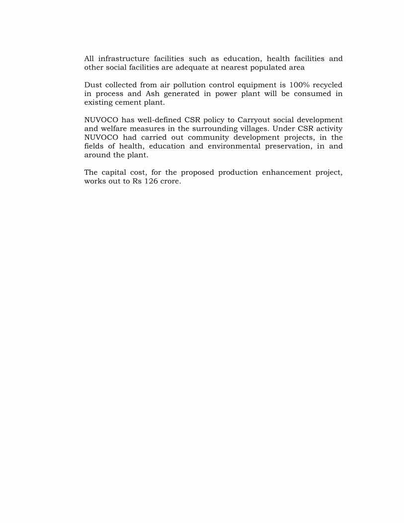
Power Cost from CSEB1 Total Energy Required 176.64 Mio Kwh per
annum2 Contract Demand with grid 27,000 KVA3 Maximum Power Demand 24,500 kW3 Fixed Charges 375 Rs/KVA/Month
4 Average Energy Charges6.02
Rs/Kwh5 Electricity Duty 0.34 Rs/KwhTotal Power tariff 7.15 Rs/Kwh
B) CAPACITY OF THE CAPTIVE POWER PLANT
Captive Power plant along with WHR power plant shallmeet bulk Energy requirement of cement plant while peakrequirement shall be met from CSEB grid.
The power plant configuration / size under various options willbe selected based on the unit size available from various powerplant suppliers.
C) UNIT SIZING
The capacity of the power plant has been worked out under PresentOperation condition with the proposed WHRS Plant with netavailable power - 6.5 MW
The power scenario under various operating condition is as follows:
Various Operating Scenarios• Scenario 1 Normal Operating Condition when CPP , WHR PP &
Grid• Scenario 2 Operating Condition when WHR PP is not avaliable• Scenario 3 Normal Operating Condition when WHR PP & Grid is
not Avaliable• Scenario 04 Operating Condition when CPP is not avaliable
Scenario 01 Normal Operating Condition when CPP, WHR PP & Grid isAvailable
Sn. Plant Generation/Installed capacity
Auxiliarypowerin MW
Net availablepower for Cement
PlantIn MW (peak)
1. CPP (ThermalCoal based)
20.00 2.00 18.00
2 WHRS 7.0 0.5 6.53 CSEB supply 7.0 MVA
( demand )0.0
Total in MW 24.5

Scenario 02 Operating Condition when WHR PP is not available
Sn. Plant Generation/Installed capacity
Auxiliarypowerin MW
Net availablepower for Cement
PlantIn MW (peak)
1. CPP (ThermalCoal based)
20.00 2.00 18.00
2 WHRS 0.0 0.5 0.03 CSEB supply 7.0 MVA
( demand )6.5
Total in MW 24.5
Scenario 03 Normal Operating Condition when WHR PP & Grid is notAvaliable
Sn. Plant Generation/Installed capacity
Auxiliarypowerin MW
Net availablepower for Cement
PlantIn MW (peak)
1. CPP (ThermalCoal based)
20.00 2.00 18.00
2 WHRS 0 0.0 0.03 CSEB supply 7.0 MVA
( demand )0.0
Total in MW 18.0
During above condition Power requirement of the upto Clinkerisationsection is met & Cement mills shall be stopped
Scenario 04 Normal Operating Condition when CPP is not Avaliabledue to annual shut down
Sn. Plant Generation/Installedcapacity
Auxiliarypowerin MW
Net availablepower for Cement
PlantIn MW (peak)
1. CPP (ThermalCoal based)
20.00 0.0 0.0
2 WHRS 0.0 0.0 0.03 CSEB supply 7.0 MVA
( demand )6.0
4 DG set(one DG set willbe operated)
7.0 MVA 5.0
Total in MW 11.0

The stoppage of CPP shall be Synchronised with the Pyro shut down& only Cement grinding and Packing plant shall be operated
The normal operating Condition is as per Scenario 1 above.
The condition defined under Scenario 2 to 4 are only intermittentconditions & expected to be for very short duration in the plant.However same are analysed to have uninterrupted power supply foroperation of the pyro section, except for scenario 04 wherein PyroShut down shall be synchronised with Power plant annual shut down
Considering above, 20 MW captive power plant is most suitable forimplementation.
Based on the above, revised techno economic feasibility has beenprepared. Based on the above power requirement shall be met fromThermal power plant , WHRS power plant & CSEB Grid.
To meet complete power requirement of Cement Plant duringoutage of Captive Power Plant, CSEB power supply demand shallbe retained as 7.0 MVA.
Based on the above the Optimum capacity of Power Plant shall be20 MW.
(VI) EXPORT POSSIBILITY
No export is proposed
(VII) DOMESTIC/EXPORT MARKETS.
Power generated will be used for captive consumption
(VIII) EMPLOYMENT GENERATION (DIRECT AND INDIRECT) DUE TOTHE PROJECT
Additional employments of about 43 persons & 24 contract personsrequired for proposed power plant.
3 PROJECT DESCRIPTION
(I) TYPES OF PROJECT INCLUDING INTERLINKED ANDINTERDEPENDENT PROJECT, IF ANY
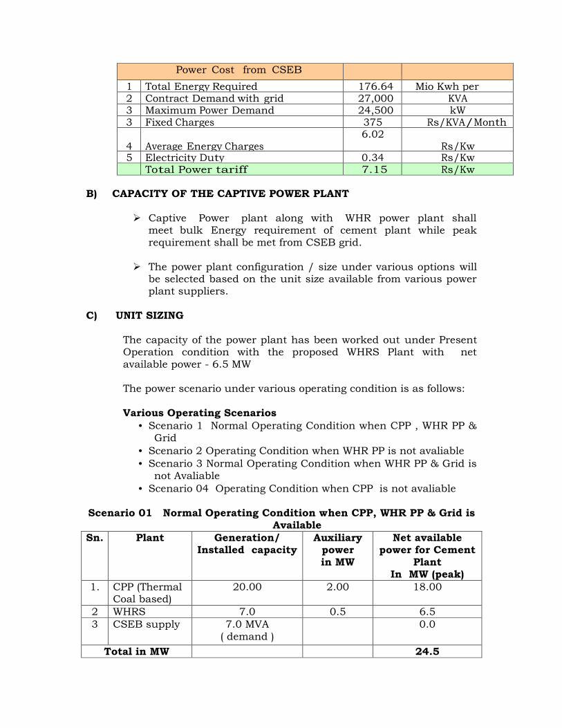
NUVOCO proposes to set up a 20 MW Coal based Thermal PowerPlant to meet the power requirement of the existing cement plant.
The proposed new unit will be located within the existing cement plantcomplex. No additional land or site is required. Keeping in view ofutilizing some of the common existing infrastructure.
(II) LOCATION (MAP SHOWING GENERAL LOCATION, SPECIFICLOCATION AND PROJECT BOUNDARY & PROJECT SITE LAYOUTWITH COORDINATES.
Arasmeta Coal based Power Plant located near Arasmeta village,Akaltra Tehsil Janjgir-Champa district, Chhattisgarh state. Fig – 1shows the location map of the plant site. The plant is geographicallylocated between 21°57'51.44"N to 21°58'21.43"N, Latitude and82°20'42.01"E to 82°21'28.10"E Longitude and part of study areafalls within the Survey of India Toposheet No. 64 K/5 (Scale :1:50000).
Nearest railway line connecting Bilaspur – Janjgir of South EasternRailway line is located at a distance of 5.6 km in Northern directionfrom the site. The nearest railway station is located at Kotmi – sunarpassanger Hlt which is 6.0 km in NNE from the site. The majorRailway Station is Bilaspur which is at a distance of 22.8 km in WNWwith respect to the Plant site.
Lilgar Nadi flows at a distance of 1.8 km in SW with flow from N to S.Arna or Arpa River flows at a distance of 12.5 km in SW from thePlant site with flow from NW to SW. Seonath River flows at a distanceof 22.4 km in SW from the site.
Key map showing the location of various features around the site isshows in Fig – 2.
Bilaspur is the major city which is located at a distance of 24.8 kmfrom the site in WNW direction.


The National Highway (NH-200) connecting Bilaspur – Janjgir islocated at a distance of about 4.0 km in Southern direction to thePlant site.
There are no wild life sanctuaries, elephant/tiger reserves within 10-km radius of the study area.
Kotmi-sunar Crocodile Park is at a distance of 6.4 km in NNE withrespect to the site.
Nearest Settlements from the Plant site
Arasmeta – 1.2 km – SSW Parsada – 1.3 km – WNW Nawapara – 2.5 km – NW Bohapara – 0.8 km – N Amora – 1.0 km – E
There are no Reserved and Protected forests within study area of 10km Radius.
Salient features of the Plant site are given in Table – 1.0 & Fig- 3shows the study area of 10 km radius around the Plant site.

TABLE – 1.0SALIENT FEATURES OF THE PLANT SITE
Feature DetailsAltitude 260 m above msl
Longitude & Latitude 21°57'51.44"N to 21°58'21.43"N, 82°20'42.01"Eto 82°21'28.10"E
Village, District, State Arasmeta Village, Janjgir-Champa District ofChattisgarh
IMD Station Champa – 24.8 km - WNWDistrict head quarters Janjir – 23.6 km - ENE
Max. Temp. oC 48
Min. Temp. oC 6.2Relative Humidity% 19- 88Annual rainfall 1354.1 mm
Topography PlainSoil Type Black Cotton Soil
Nearest Water bodiesRiver/nala
Lilgar Nadi – 1.8 km – SWArna or Arpa River - 12.5 km – SWSeonath River- 22.4 km – SWUpka Nala – adjacent - N
Nearest Highway National Highway (NH-200) ConnectingBilaspur – Janjgir –4.0 km – S
Nearest Railway station Kotmi – sunar passanger Hlt - 6.0 km - NNE
Nearest Railway Junction Bilaspur – 22.8 km - WNW
Nearest IndustriesKSK Mahanadi power company – 5.9km – ESEKSK Power Plant – 0.5km – EVerdha Power Plant– 5.0 km – E
Nearest Village
Arasmeta – 1.2 km – SSWParsada – 1.3 km – WNWNawapara – 2.5 km – NWBohapara – 0.8 km – NAmora – 1.0 km – E
wild lifesanctuaries/Natioal Parks
Kotmisunar Crocodile Park- 6.4 km - NNE
Nearest City Bilaspur – 24.8 km - WNW
Interstate boundary Chattisgarh – Madhya Pradesh – 100.00 km-NW
Nearest Air port Bilaspur – 24.0 km – WNWRaipur – 107.0 km - SSW
Nearest Forest NoneHistorical places None
*all distances mentioned in the above table are aerial distances


(III) DETAILS OF ALTERNATE SITES CONSIDERED AND THE BASISOF SELECTING THE PROPOSED SITE, PARTICULARLY THEENVIRONMENTAL CONSIDERATIONS GONE INTO SHOULD BEHIGHLIGHTED.
The proposed new unit 20 MW Coal based Power plant will be locatedwithin the existing cement plant complex in an area of 2.5 Ha. Noadditional land or site is required. Keeping in view of utilizing some ofthe common existing infrastructure.
(IV) SIZE OR MAGNITUDE OF OPERATION.
The Proposed new unit is 20 MW Coal based Power plant will belocated within the existing cement plant complex.
Fuel proposed for the Power Plant is Coal hence conventional Rankinesteam cycle plant has been considered for 1 x 20 MW CPP.
POWER CYCLE CONFIGURATION
In the conventional steam system operating on Rankine cycle, themain equipment is the steam generator, steam turbine & Air CooledCondenser with their auxiliaries.
The utility system includes fuel storage system, fuel handling system,Water treatment plant, fire water system, cooling tower for auxiliaries,ash handling system and compressed air systems etc. The followingfactors have influenced the selection of major equipment:
The efficiency of steam power cycle improves with the increase inthe inlet steam temperature and pressure, as has been establishedby thermodynamics.
The basic power cycle configuration chosen for the 1x20 MW wouldbe with pressure of 107 ata and temperature of 535° C at turbineinlet and following tap off for regeneration:
• Two high pressure• One low pressure• One de-aeration
The following configurations will be adopted for the power plant:-
A Steam Turbine GeneratorA Type of turbine CondensingB No. and ratings of
turbine01no. (20MW) of inletparameters, 107 ata & 535oC
C Capacity 20 MW MCRd No. of Bleeds 4nos. 2HP, 1LP and 1 Deaerator

The steam generator design parameters will be as follows
B Boiler type CFBC1 Super-heater outlet pressure ata 1102 Super-heater outlet temperature (oC) 540 ± 53 Feed water inlet temperature (oC) 2304 Excess air (%) Not more than 255 Boiler outlet flue gas temperature(oC) 150 (max.)6 Dust concentration at chimney (mg/Nm3) 30 (max.)
The selected configuration consist of 1 x 20 MW power plant withCFBC boiler with a continuous rating of 90 TPH connected to a singleturbo-generator of 20 MW nominal capacity.
The type of turbine & boiler are discussed below:
TURBINE
The 20 MW size turbine is having an axial length of approx. 4.5meters. Hence it will be possible to provide 4 nos. of steam tap offnozzles in the turbine for feed heating making the turbine a fourextraction cum condensing type. With this configuration the powercycle efficiency can be improved.
Based on the above analysis, following configurations will be adoptedfor the each units:
A Steam Generatora No. and ratings of Boiler 1 no. with Maximum Continuous
rating 90 TPH & 540oCb Type of Boiler CFBCc No. of boiler fans 2 x 60% duty for ID & SA & SA
Fand Type of Atmospheric
pollution control systemElectro static precipitators withoutlet dust concentration lessthan 30 mg / Nm3.
B Steam Turbine Generatora No. and ratings of turbine 1 no. for each unit of inlet
parameters, 105 kg & 535oCb Capacity 20 MW Maximum Continuous
ratingc No. of controlled extractions 4 nos.2 HP, 1MP and 1 LPd Type of exhaust steam
coolingWith Air cooled condenser

(V) PROJECT DESCRIPTION WITH PROCESS DETAILS (A SCHEMATICDIAGRAM/FLOW CHART SHOWING THE PROJECT LAYOUT,COMPONENTS OF THE PROJECT ETC. SHOULD BE GIVEN.
Power generation process is based on Rankine Steam cycle. The steamgenerated in the boiler when expanded through a turbine, turns theturbine shaft, which is tandem coupled to an electric power generator.
The Power plant is aimed at generation of 20 MW of electric powerwith one CFBC boiler of 90 tph capacity connected to TurboGenerator set of 20 MW.
The steam generator design parameters will be as follows
Maximum continuous rating (MCR) (T/hr) 90Super-heater outlet pressure (kg/cm2 (g)) 110Super-heater outlet temperature (oC) 540 + 5Feed water inlet temperature (oC) at ecoinlet
230
Excess air (%) Not more than 25Boiler outlet flue gas temperature (oC) 150 (max.)Dust concentration at chimney (mg/Nm3) 30 (max.)
The steam generator will be with following auxiliaries:
The steam generator will be provided with a steam drum and thedrum will be of fusion-welded type. The steam drum will be withnecessary nozzle connections for the steam outlets, safety valves, feedwater inlets, down-comers, continuous blow down, level indicators,chemical dosing, sampling connection, drains and vents to assure therequired steam purity.
STEAM TURBINE AND AUXILIARIES
STEAM TURBINE
This project envisages 20 MW multi extraction-cum-condensing turbo-generators.
The turbine will be designed for the operation with the inletsteam parameters at 110 ata and 535°C and will be withautomatic controlled extraction steam.
The turbine will be horizontal, single cylinder, triple extraction-cum-condensing type. All casings and stator blade carriers willbe horizontally split.
The controlled extraction steam from the turbine will bedelivered to the heaters/de-aerators in saturated condition.

A de-super heater to bring the steam temperature from theextraction steam temperature down to the required level isenvisaged.
(VI) RAW MATERIAL REQUIRED ALONG WITH ESTIMATED QUANTITY,LIKELY SOURCE, MARKETING AREA OF FINAL PRODUCTS/S,MODE OF TRANSPORT OF RAW MATERIAL AND FINISHEDPRODUCT.
Fuel proposed for thermal power plant will be Indian Coal/ImportedCoal/Washery reject or combination of above fuels.
FUEL ANALYSIS (% BY WEIGHT)
Fuel & Lime stone analysis for design fuels for Boiler1 Imported coal Design Parameter
Proximate AnalysisFixed Carbon % 36-43Volatile matter % 28.01Ash % 14.14Moisture % 15.5Ultimate AnalysisCarbon % 61.89Hydrogen % 4.39Oxygen % 11.0Moisture % 15.50Sulphur % 0.50Nitrogen % 1.24Ash % 5.22Fuel Gross CalorificValue
kcal/kg 5950
Ash analysisSiO2 % 57-62Al2O3 % 20-32Fe2O3 % 4-14CaO % 1-6MgO % 0.6-2Na2O % 0.07-1.2TiO2 % 1-2K2O % 0.07-1.2SO3 % 0.06-0.22P2O5 % 0.2-0.7
2 Indian CoalProximate AnalysisFixed Carbon % 24.5Volatile matter % 20.5Ash % 45Moisture % 10

Ultimate AnalysisCarbon % 36.20Hydrogen % 1.70Oxygen % 6.0Moisture % 10.0Sulphur % 0.30Nitrogen % 0.60Ash % 45.0Fuel Gross CalorificValue
kcal/kg 3200
Ash analysisSiO2 % 45-65Al2O3 % 10-20Fe2O3 % 6-10CaO % 2-10MgO % 1-3Na2O % 1-5TiO2 % 1-1.5K2O % 1-5SO3 % 2-4P2O5 % 0.5
3 Washery rejectsProximate AnalysisFixed Carbon % 15Volatile matter % 15Ash % 60Moisture % 10Ultimate AnalysisCarbon % 22.92Hydrogen % 1.59Oxygen % 4.52Moisture % 10.0Sulphur % 0.30Nitrogen % 0.47Ash % 60.0Fuel Gross CalorificValue
kcal/kg 2150
Ash analysisSiO2 % 55-65Al2O3 % 20-30Fe2O3 % 2.5-7.5CaO % 2.5-7.5MgO % 1-2Na2O % 0.05-0.15TiO2 % 0.05-0.15K2O % 0.5-0.9SO3 % 0.1-0.15

P2O5 % Traces4 Density of fuel and ash
Fuel Density for volumecalculation
kg/m³ 800
Fuel Density for weightcalculation
kg/m³ 1200
Ash density for volumecalculations
kg/m³ 600
Ash density for weightcalculations
kg/m³ 1100
5 Lime stone analysisCaCO3 % 75MgCO3 % 2.5SiO2 % 10Al2O3 % 2Fe2O3 % 0.5K2O % 0.25Ma2O3 % 0.35Surface moisture % 2-3Inherent moisture % 1-2
The maximum consumption of any fuel at given time is given below
FUEL REQUIREMENT - 20 MW COAL BASED POWER PLANTSr.No Fuel
ConsideredGCV ofFuelKcal/kg
Fuelrequiredton/ day
Fuel requiredper annumMTPA
1 ImportedCoal
5950 182.09 0.060
2 Indiancoal
3300 334.08 0.110
3 WasheryCoal
2150 521.61 0.172
The operation fuel will be based on the economic & reliable operationof the Power Plant.
Presently for cement plant coal is being transported to the site bymeans of rail. Wagon tippler system is available at site for unloading.Apron conveyor and primary crusher is available below the wagontippler. Unloaded coal transported to the covered coal shed with thehelp of belt conveyor and staking is done with the help of boomconveyor.

(VII) RESOURCES OPTIMIZATION/ RECYCLING AND REUSEENVISAGED IN THE PROJECT, IF ANY, SHOULD BE BRIEFOUTLINED.
The waste water generated from Power plant will be used in cementplant & the raw water requirement thus is reduced to that extent.
(VIII) AVAILABILITY OF WATER ITS SOURCES, ENERGY /POWERREQUIREMENT AND SOURCES SHOULD BE GIVEN,
POWER: The present power requirement of 27 MVA is met fromCSEB grid.
Currently the cement plant electrical energy requirement is being metfrom the Chattisgarh State Power Distribution Company Limited(CSPDCL) .Plant has 132kV/6.6kV receiving substation having threestep down transformer of 12 MVA, 132kV/6.6 kV.
Maximum power requirement of the Cement plant is 23 MW whereasaverage power requirement is 21.5 MW. NUVOCO Arasmeta cementplant also has installed 3x 6MW HFO based DG power plant.
WATER: Water requirement of power plant is 280 m3/day and issourced from lilagar River. Raw water will be tapped from the existingraw water storage tank. Dedicated pumping system will be installed atexisting raw water tank to feed the raw water for CPP.
(IX) QUANTITY OF WASTES TO GENERATED (LIQUID AND SOLID) ANDSCHEME FOR THEIR MANAGEMENT/DISPOSAL.)
Ash generated (0.49 MTPA- Max) from the power plant will beconsumed in cement plant.
Waste water generated in power plant is reused in cement plant
(X) SCHEMATIC REPRESENTATIONS OF THE FEASIBILITY WHICHGIVE INFORMATION OF EIA PURPOSE.
Not applicable.
4 SITE ANALYSIS
(I) CONNECTIVITY
Nearest railway line connecting Bilaspur – Janjgir of South EasternRailway line is located at a distance of 5.6 km in Northern directionfrom the site. The nearest railway station is located at Kotmi – sunarpassanger Hlt which is 6.0 km in NNE from the site. The major

Railway Station is Bilaspur which is at a distance of 22.8 km in WNWwith respect to the Plant site.
The National Highway (NH-200) connecting Bilaspur – Janjgir islocated at a distance of about 4.0 km in Southern direction to thePlant site.
(II) LAND FORM, LAND USE AND LAND OWNERSHIP.
The proposed CPP will be located in an area of 2.5 Ha within theexisting cement plant complex of 82.00 Ha. No additional land or siteis required. Keeping in view of utilizing some of the common existinginfrastructure, NUVOCO proposes to locate the new units within theexisting cement plant complex
(III) TOPOGRAPHY (ALONG WITH MAP)
It is a flat land and the average elevation is 260 m above MSL. Fig – 3shows the 10 km radius around the plant site.
(IV) EXISTING LAND USE PATTERN (AGRICULTURE, NON-AGRICULTURE, FOREST, WATER BODIES (INCLUDING AREAUNDER CRZ)), SHORTEST DISTANCES FROM THE PERIPHERY OFTHE PROJECT TO PERIPHERY OF THE FORESTS, NATIONALPARK, WILD LIFE SANCTUARY, ECO SENSITIVE AREAS, WATERBODIES (DISTANCE FORM THE HFL OF THE RIVER), CRZ. INCASE OF NOTIFIED INDUSTRIAL AREA, A COPY OF THEGAZETTE NOTIFICATION SHOULD BE GIVEN)
The proposed new unit will be located within the existing cement plantcomplex. The land breakup of the plant is given below
LAND BREAKUPArea (ha)
Cement PlantRooftop area of buildings/sheds
8.0
Road/paved area 7.68Green belt area 31.9Open land 31.92Proposed CPP 2.50Total area of land 82.00
There is no wild life sanctuary, national park, eco-sensitive areawithin the 10 km radius of the project site.
Kotmi-sunar Crocodile Park is at a distance of 6.4 km in NNE withrespect to the site.

(V) EXISTING INFRASTRUCTURE.
Existing infrastructure include railway siding and well developedroads, storm water drains with adequate storage space for flyash andparking area.
(VI) SOIL CLASSIFICATION
Predominantly clayey soil
(VII) CLIMATIC DATA FROM THE SECONDARY SOURCES.
In general the climate of this area is dry. Summer starts from mid ofFebruary and continues up to first week of June, when the monsoonbreaks. The monsoon continues till the end of October. Winter isbetween November and middle of February. The peak of summer is inMay. The maximum temperature is about 48oC. During the coldmonths of December the temperature falls to 6.2oC.
The average annual rainfall observed based on the 10 years IMD datais 1354.1 mm. More than 85% of the rainfall is received during themonsoon season. On an average there are about 65 rainy days in ayear. The maximum numbers of rainy days occur in the months ofJuly-August.
(VIII) SOCIAL INFRASTRUCTURE AVAILABLE.
All infrastructure facilities such as education, health facilities andother social facilities are adequate.
5. PLANNING BRIEF.
(I) PLANNING CONCEPT (TYPES OF INDUSTRIES, FACILITIES,TRANSPORTATION ETC) TOWN AND COUNTRYPLANNING/DEVELOPMENT AUTHORITY CLASSIFICATION
The proposed 20MW Coal based power plant will be located within theexisting cement plant complex. No additional land or site is required.Keeping in view of utilizing some of the common existinginfrastructure, NUVOCO proposes to locate the new unit within theexisting cement plant complex. The site is well connected by Rail, roadand air network.
(II) POPULATION PROJECTION.
No increase in population is anticipated due to increase of production
(III) LAND USE PLANNING (BREAKUP ALONG WITH GREEN BELT ETC)
Land use breakup is given in following table:
LAND BREAKUPArea (ha)
Cement plantRooftop area of buildings/sheds
8.0
Road/paved area 7.68Green belt area 31.9Open land 31.92Proposed new unit 2.50Total area of land 82.00
Fig – 4 shows the location of new unit i.e., 20 MW Coal based Powerplant within the existing cement plant complex.


(IV) ASSESSMENT OF INFRASTRUCTURE DEMAND (PHYSICAL &SOCIAL)
The project will have the following:-
Power house building Boilers and Auxiliaries Air Cooled Condenser Coal Handling system. Coal storage System after unloading coal from the Wagon Pump house / Aux Cooling Tower DM plant Ash handling system Water storage system
Following configurations have been proposed for Power Plant
CaptivePowerPlant
a. No. and ratings 1 no. each of MCR 90 TPH & 540oCb. Type of Boiler Circulating Fluidised Bed Combustion
(CFBC)c. No, of boiler fans 2 x 60% duty ID & SA and PA-fan for
boilerd. Type of APCS Electro static precipitators
SteamTurbineGenerator
a. No. and ratings ofturbine
1 no. Turbine with inlet parameters,110 kg/cm2 & 535°C
b. Capacity 1x 20 MW MCRc. No. of controlled
extractions4 nos HP, 1no MP and 1no LP
d. Type of exhaustCondensate Cooling
Air cooled condenser
(V) AMENITIES/ FACILITIES.
All infrastructure facilities such as education, health facilities andother social facilities are adequate at nearest populated area

6 PROPOSED INFRASTRUCTURE
(I) INDUSTRIAL AREA (PROCESSING AREA)
The proposed infrastructure of the power plant is detailed below:
STEAM GENERATOR
The steam generating system for each unit of 20 MW power plant willconsist of one no. 90 TPH capacity boiler with all the auxiliaries.
The boilers will be of circulating fluidized bed type, naturalcirculation, balanced draft, and membrane wall radiant furnacedesign with three (3) stage super-heaters and inter-stage de-superheater.
The steam generator design parameters will be as follows:
Maximum continuous rating (MCR) (T/hr) 90Super-heater outlet pressure (kg/cm2 (g)) 110Super-heater outlet temperature (oC) 540 ± 5Feed water inlet temperature (oC) at eco inlet 230Excess air (%) Not more than 25Boiler outlet flue gas temperature (oC) 150 (max.)Dust concentration at chimney (mg/Nm3) 30 (max.)
The steam generator will be with following auxiliaries:
The steam generator will be provided with a steam drum and thedrum will be of fusion-welded type. The steam drum will be withnecessary nozzle connections for the steam outlets, safety valves, feedwater inlets, down-comers, continuous blow down, level indicators,chemical dosing, sampling connection, drains and vents to assure therequired steam purity.
FURNACE
The furnace envelope will be constructed of fully water-cooledmembrane/fin welded walls and the construction will be gas pressuretight.
The furnace bottom will be covered with an air nozzle tube plate,below which the fluidizer air plenum will be located. The coal ofproperly graded size will be brought to the furnace through over bedfeeding system.

SUPER HEATER
Super-heater system will be of three (3) stage design with inter-stagede super heating to achieve the rated steam temperature over 60% to100% MCR load. The super-heater will be combination of convectionand radiation type.
The inter-stage attemperator or a de-super-heater of spray type will belocated between the two super-heater stages, to control the finalsteam temperature at 540 ± 5oC between 60% to 100% MCR load
ECONOMISER
The economiser will be located downstream of the super-heaters andevaporator sections. The economiser will be of bare tube construction,inline arrangement, counter flow type and the economiser will bedesigned for inlet temperature of 230oC.
AIR HEATER
Air heater will be arranged as the last heat recovery sectiondownstream of economiser. Air heater will be recuperative type withflue gas flowing inside the tubes and the combustion air flowing overthe tubes.
DRAFT SYSTEM
The draft system for the steam generator will be suitable of producinga balanced draft with sub-atmospheric pressure condition in thefurnace.The system will comprise of:
• 2 x 60% PA fan• 2 x 60% ID fan• 2 x 60% SA fan
AIR POLLUTION CONTROL SYSTEM
Environmental considerations and protection measures assumegreater importance for the project. NUVOCO will ensure that theproposed power plant causes no adverse impact on the area.
The proposed project is planned to meet all environmental norms andfurther improve the environs in the area. NUVOCO propose to useState of Art Technology with computer controls to ensure highefficiency in plant operations. This would result in low per unit energyconsumption and low particulate emissions.

Air pollution control system (APCS) comprising of Electro-staticPrecipitator with all its accessories for the boiler will be provided. TheAPCS will be designed to provide an outlet dust concentration lessthan 30 mg/Nm3, with the boiler operating with the range of fuelproperties indicated.
The ESP will be designed to provide an outlet dust concentration levelof 30 mg/Nm3 with all field in service, with the CFBC boiler operatingwith the design basis as specified for the worst operating condition ofthe fuel composition mentioned and overall dust collection efficiency99.93% with all field in service.
The aspect ratio of the ESP (electrode zone) will be optimally selected,so as to minimize re-entrainment and carry over of the collected dust,and for assured ESP performance.
SO2 emissions will be controlled by dosing lime stone to sulphurcapture about 90% of emissions; use of appropriate technologies andemission control technologies such as sorbent injection.
In conclusion RCC Stacks with 90 mtr of height will be considered andfor further reduction in sulphur dioxide as well as stack height.
In addition to above, for coal handling system dedicated bag filters willbe installed to restrict emission less than 30 mg/nm3.
HP & LP DOSING SYSTEM
Steam generator will be with High Pressure (HP) dosing and LowPressure (LP) dosing system. The HP dosing system will be based on‘tri-sodium phosphate’ dosing and this will be dosed in boiler water totake care of the ingress of the hardness salts and to increase theboiler water pH. The LP dosing system will be based on ‘hydrazine’dosing and this is dosed in the feed water to scavenge the last tracesof oxygen and to increase the feed water pH.
BLOW DOWN TANK
One Continuous Blow Down tank (CBD) and one Intermittent BlowDown tank (IBD) will be provided for boiler. The flash steam from theCBD tank will be piped to the de-aerator and outlet of the IBD tankwill be vented to the atmosphere.
DE-AERATOR
One De-aerator of de-aerating capacity equal to twenty percent (20%)higher than the gross MCR steam generation capacity of boiler with ade-aerated water storage tank of minimum 10 minutes operation.

BOILER FEED WATER PUMP
One working and one standby boiled feed water pumps have beenenvisaged.
STEAM TURBINE AND AUXILIARIES
STEAM TURBINE
This project envisages 20 MW multi extraction-cum-condensing turbo-generators.
The turbine will be designed for the operation with the inletsteam parameters at 110 ata and 535°C and will be withautomatic controlled extraction steam.
The turbine will be horizontal, single cylinder, triple extraction-cum-condensing type. All casings and stator blade carriers willbe horizontally split.
The controlled extraction steam from the turbine will bedelivered to the heaters/de-aerators in saturated condition.
A de-super heater to bring the steam temperature from theextraction steam temperature down to the required level isenvisaged.
LUBRICATION SYSTEM
A pressure lubrication and control oil system will be provided for theturbo-generator unit to supply oil at the required pressure to thesteam turbine, gearbox, generator and governing system. Thelubrication oil system will supply oil to the turbine generator under allthe load conditions, including the turning gear operation.
The oil system will be with the following:
One hundred percent (100%) capacity centrifugal/gear type, main oilpump.
One (1) no. of one hundred percent (100%) capacity auxiliary oilpump of centrifugal type, arranged to cut in automatically if theoil pressure falls to a preset value. This pump will also meet therequirements during the start up and shut down.
One (1) no., centrifugal type, DC emergency oil pump to provideadequate lubrication in the event of a failure of the main drivenpump. This pump also will cut in automatically at a preset valueof the oil pressure.

Emergency gravity lube oil system comprising of overhead tankwith SS lining and complete interconnecting SS oil piping.
2x100% capacity (one working and one standby) water-cooledair coolers.
2x100% duty oil filters
TURBINE GOVERNOR
The turbine governing system will be electro-hydraulic type, designedfor high accuracy, speed and sensitivity of response. The governor willensure controlled acceleration of the turbo generator and will preventover-speed without tripping the unit under any operating condition orin the even of maximum load rejection. The governor will beconfigurable in the field.
The governing system will have the following important functions:
Speed control Over speed control Load control Steam pressure control
The governing system will be digital governor with all parametercontrol from plant DCS system.
AIR COOLED CONDENSER
The waste heat produced in the thermal process of the plant has to betransferred to the atmosphere by using adequate cooling system.Environmental concern and climatic conditions are the main factorsin the selection of the most suitable power station process.
Since water availability is concern as such to save natural resources &to have sustained generation Air cooled Condenser is considered withAir Cooled Condenser approx. 90% of the water is saved. The basicConfiguration of Air cooled condenser is as follows

TURBINE CONTROL
The turbine control will be through the centrally located DistributedControl System. The control system will provide redundancy for keyfunctions by use of separate sensors and monitors. The controlsystem will include all the standard control monitoring and alarming.
In addition to centralised monitoring, some of the essentialparameters mounted in local will be:
Inlet steam pressure temperature and flow Controlled extraction steam pressure and temperature Exhaust steam pressure, temperature and flow Lube oil header pressure Control oil header pressure Steam turbine/generator speed indicator Steam turbine/generator stop push button Turbine back propose control Emergency shutdown push button
FUEL HANDLING AND PREPARATION
Presently for cement plant coal is being transported to the siteby means of rail. Wagon tippler system is available at site forunloading. Apron conveyor and primary crusher is availablebelow the wagon tippler. Unloaded coal transported to thecovered coal shed with the help of belt conveyor and staking isdone with the help of boom conveyor.
Designed capacities of the various components of the existingcoal handling system is as under-

Sr.No. Parameters Unit Value1 Wagon tippler TPH 6002 Apron conveyor TPH 7503 Primary crusher TPH 6004 Boom conveyor TPH 7505 Covered storage
capacityTPH 15000
6 Grab crane TPH 5
Average coal requirement for the cement plant is around 800MT per day. Adequate capacity is available in existing coalunloading and storage system and same will be utilised for theup coming power plant.
Another garb crane will be considered for the feeding of the coalfor the coming power plant.
Dedicated secondary crusher, primary and secondary screeningsystem will be installed for the coal fired power plant. Grabcrane will be feeding the coal from the stock pile to the crushercum screen house by means of belt conveyor and the productfrom the crusher cum screen house will be fed the power plantbunker by belt conveyor. Reject from the screen will be also re-circulated to system by belt conveyor.
COAL STORAGE & UNLOADING SYSTEM
Adequate capacity is available in existing coal unloading and storagesystem and same will be utilised for the up coming power plant.

COAL STORAGE & RECLAIM AT POWER PLANT
Adequate capacity is available in existing coal unloading and storagesystem and same will be utilised for the upcoming power plant.
COAL SECONDARY CRUSHING AND STORAGE IN BUNKER
For boiler application coal has to be reduced to average 6 to 8 mm sizewhich necessitates crushing of the coal.
The vibrating flip flop primary screen will be provided up stream ofcrusher to screen out coal size below 6 mm and coarse particle will befed to the impact crusher. The output from Crusher will be fed to thesecondary Flip Flop vibrating screen. The oversize particle above 6mmfrom Screen will be re-circulated to the Crusher. The 6 to 8 mm Coalwill be conveyed to the coal bunker near the boiler.
SIZING OF THE CONVEYOR, CRUSHER AND SCREEN
The Sizing of the Coal Handling system will be taking intoconsideration one shift working with worst fuel viz. Washery rejects.
Based on above, the sizing of the screen and crusher will be finalizedas follows :-
Screen : 75 TPH (Primary & Secondary) Crusher : 75 TPH
ASH HANDLING
The fuels proposed to be used in this project will have a gross calorificvalue elaborated in chapter 4 viz.
The ash generated from the above will be about 20 T / hr. maximumwhile using Washery rejects.
Out of this 30% is expected to be Bed Ash and rest 70% will be Flyash to be collected from Boiler EP/ Economizer/ Cyclone. The detailsof quantity are as furnished below:-
Fly ash will be transported pneumatically with the help of densephase pneumatic to the fly ash silo from Economizer, Cycloneand EP. The fly ash from the silo will be transported to groupcement plant by tanker.
Bed Ash will be collected from overflow spouts into ash coolerhoppers. Ash from the hoppers, after sufficient cooling will bedischarged through ash vessel of pneumatic conveying systemto bed ash silo. bed ash will be disposed through trucks.
Fly ash silo has been considered of capacity of 200m3.
Bed ash silo has been considered of capacity 75 m3.
(II) RESIDENTIAL AREA (NON PROCESSING AREA)
Additional quarters to accommodate captive power plant employeeswill be provided within existing colony premises.
(III) GREEN BELT.
Green belt in an area of 33% has been developed inside the plantboundary
(IV) SOCIAL INFRASTRUCTURE.
NUVOCO has well-defined CSR policy to Carryout social developmentand welfare measures in the surrounding villages. Under CSR activityNUVOCO has initiated community development projects, in the fieldsof health, education and environmental preservation, in and aroundthe plant.
(V) CONNECTIVITY (TRAFFIC AND TRANSPORTATION ROAD/RAIL/METRO/ WATER WAYS ETC)
Adequate facilities with railway siding and roads are existing. Noadditional connectivity is required
(VI) DRINKING WATER MANAGEMENT (SOURCE AND SUPPLY OFWATER)
Additional water of 280 m3/day will be required and the same will bemet from River lilagarh
(VII) SEWERAGE SYSTEM.
Plant waste water dispose in soak Pit via septic tank.
NUVOCO is operating a full-fledged sewage treatment plant (STP)designed for a maximum load of 400 m3/day to treat wastewatergenerated from Colony. STP capacity is adequate for taking additionalwastewater.
(VIII) INDUSTRIAL WASTE MANAGEMENT.
Wastewater generated from the power plant will be treated and usedin the cement plant
(IX) SOLID WASTE MANAGEMENT
Dust collected from air pollution control equipment is 100% recycledin process, Ash generated in the proposed power plant will beconsumed in existing cement plant.
(X) POWER REQUIREMENT & SUPPLY / SOURCE.
SOURCES OF POWER ENERGY
NUVOCO is contemplating to have a sustainable, reliable andeconomic power source to the operation of cement plant.
The most optimum size of the power plant proposed is 20 MW grosswith net power available as 18 MW, the power plant will meet 63% ofthe energy requirement of the cement plant. 27% of the Energyrequirement will be met from WHR PP thereby in-house generation tooperate cement plant will be 90%.
In addition to above the average loading of the power plant underpresent operating condition will be 85 % thereby operating efficiencywill be optimum.
The power generation will be at 6.6kV and it will be evacuated at6.6kV only through power cables. Power cables from the outgoingfeeder (HV switch board at CPP) of the CPP will be hooked up with thespare DG incomer feeder of 2500 A available at the bus section 2 ofthe HV switch board at existing MRSS.

The sources of power/energy with gross & net output andconsumption are detailed below:
ProposedCPP
Gross generation(mio kwh)
Auxiliary powerConsumption perannum (mio kwh)
Netgeneration(mio kwh))
1X20MW 123 12.3 110.7

7. REHABILITATION AND RESETTLEMENT (R & R) PLAN.
(I) POLICY TO BE ADOPTED (CENTRAL/ STATE) IN RESPECT OFTHE PROJECT AFFECTED PERSONS INCLUDING HOMEOUSTEES, LAND OUSTEES AND LANDLESS LABORERS (A BRIEFOUTLINE TO BE GIVEN).
Not applicable, since the plant is already existing and new unit will belocated within the existing cement plant complex.

8. PROJECT SCHEDULE & COST ESTIMATES
(I) LIKELY DATE OF START OF CONSTRUCTION AND LIKELY DATEOF COMPLETION (TIME SCHEDULE FOR THE PROJECT TO BEGIVEN)
IMPLEMENTATION PLANNING
3 months’ time would be required for pre-project activities fromsubmission of Techno-Economic Feasibility Report till main machineryorder placement
22 months’ time would be required for project activities from mainmachinery order placement till commissioning in each phase
(II) ESTIMATED PROJECT COST ALONG WITH ANALYSIS IN TERMSOF ECONOMIC VIABILITY OF THE PROJECT
Total capital Investment Cost is Rs. 126 Crores and Rs. 20 crores willbe spent for Environmental Management Plan.
The investment cost & Cost of Generation has been worked out anddetailed in Tables below:
Estimates of InvestmentSr.No. Description Power Plant cost in Rs in
Lakhs1 Land and Site Development 1662 Buildings and other Civil Structures 12273 Plant and Machinery 94214 Technical Know-how Fees 2205 Expenses on training 256 Miscellaneous Fixed Assets 2497 Pre-operative Expenses 9148 Provision for Contingency 3479 Working Capital 4110 Total Rs in Lakhs 1260811 Total in crores (Say 126 Crores)

Mode ofFinancing
The financing of the project has been considered on thebasis of Equity: Debt ratio of 30:70 to be met as under Rs inlakhsEquity Equity 3782
Total 3782Debt Term Loan from
Financial8115
InstitutionsInterest & Up-frontcharges
711
Total 8826Grand Total 12608
Estimated Cost ofGeneration2nd year
Cost Head Rs /KWH
Variable CostCost of Coal, Water, Consumables, stores,Electricity duty
3.515
Semi-Variable/Fixed Cost Wages andSalaries, overheads, Depreciation, InterestCharges
2.185
Total Cost of Generation 5.700Cost Net of Depreciation 5.414
9. ANALYSIS OF PROPOSAL (FINAL RECOMMENDATIONS)
(I) FINANCIAL AND SOCIAL BENEFITS WITH SPECIAL EMPHASIS ONTHE BENEFIT TO THE LOCAL PEOPLE INCLUDING TRIBALPOPULATION, IF ANY IN THE AREA
The capital cost, for the proposed production enhancement project,works out to Rs. 120 Crores.
NUVOCO has implemented the following CSR measures which hasbenefited total of 5 villages around plant and 2 villages in KirariMines. All 7 villages fall under Akaltara block in radius of 24 kmsfrom plant.
CSR Focussed on Health, Livelihood and Infrastructure. Details of thesame are given below
CSR: Health Activity
Health Clinic continuing in all 6 core villages i.e. Arasmeta,Sonsari, Parsada, Amora & Kirari & Chorbhatti. In During thisperiod total approx 9400 patients were treated.

Under the Swasth Bharat initiative, a New Health centre wasstarted at the mining village - Chorebhatti by ACP.
10 Awareness Camp on Health and Sanitation, Adolescents camp,women’s health awareness camp.
Organized 7 awareness camp in ICDS centre for women andchildren and engaged professional to facilitate the community.
CSR: Livelihood Activity
Paddy Cultivation- 50 BeneficiariesNutrition Garden- 31 BeneficiariesMushroom Cultivation- 10 Women’sVegetable Cultivation- 31 FarmersSewing Center- 20 Students
Four Animal Health Camp- Deforming 727 no. of Livestock &Removal of Parasites 473 no. of livestock.
CSR: Infrastructure
Constructed Approx 1300 meters of Cement concrete road Jobcompleted in village Arasmeta, Amora, Parsada, Sonsari, Murlidih,Chorbhatti.
Construction of Four Nirmala ghat at the village ponds for thecommunity at Amora, Sonsari, Arasmeta village.
Construction of Health center building at Kirari village is underprogress.
Three solar lights installed at Amora village completed on 24-December-16 as per Panchyat proposal FY 2016-17.