Embed Size (px)
DESCRIPTION
PRDUCAHLD005.pdf
Citation preview
UCA
High Level DesignUCA
Document NumberOT-PRD.UCA.HLD.005
Copy Number
Version 1.0b – 24 February 2003
Commercial in Confidence
Issued by Open Telecommunications Limited
ACN 056 010 121
Open Telecommunications UCA
Document Control Responsibilities
This is a Controlled Document. If the Copy Number on the front cover is not in Red, you have an Uncontrolled Copy. Contact the Document Controller to ensure you have the latest version.
For additional information, contact one of the following parties:
Role Responsibility Assigned to Position
Document Owner Overall responsibility for the accuracy of the document. Nominating Reviewers and Distribution.
Peter Anderson Project Manager
Document Author Prepare the document to the Document Owner's specification.
Fiona Lodge UCA Architect
Reviewers Document accuracy in relation to their area of responsibility
See Below
Document Controller Version Control and Distribution to nominated document holders.
DMS
Address Level 2 73 Miller St, North Sydney 2060.Phone +61 2 8925 3000 Fax +61 2 9929 8477
Copyright This material is copyright. No part of this document may be reproduced in any form, stored in a retrieval system or transmitted without the prior written permission of Open Telecommunications Limited.
Confidentiality This document is classified Commercial in Confidence. It is subject to a confidentiality agreement between Open Telecommunications Limited and its customers and partners. Its contents must not be divulged to third parties.
Review and Approval
If this table does not contain the signatures of the nominated reviewers, you have an unapproved copy. Contact the Document Controller.
I have reviewed this document and authorise it for issue:
Approved by Title Signature Date
Rod Skinner Chief Architect
Fiona Lodge UCA Architect
ii Document No. OT-PRD.UCA.HLD.005 Version 1.0b 24/02/03 Commercial in Confidence
Open Telecommunications UCA
Version Control
This table must be completed for versions 1.0 and greater. Versions lower than 1.0 are draft versions prior to first release of the document. Versions ending in a letter (e.g. 1.1a) are draft revisions. The letter shall be omitted when the document is released (e.g. 1.1).
Version Number Date Issued Reason for Update
1.0 Initial release
Document No. OT-PRD.UCA.HLD.005 Version 1.0b 24/02/03 Commercial in Confidence
iii
Open Telecommunications UCA
Contents
1. Introduction 7
1.1 Purpose of Document 7
1.2 Audience 7
2. Process Architecture 8
2.1 Decomposition 8
2.2 Process Description 8
3. Thread Architecture 10
3.1 Decomposition 10
3.2 Thread Descriptions 11
4. UCA Sequence Diagrams 16
4.1 Call Handling 16
4.2 Handling the Change of Accessibility Status of Remote ISUP Point Codes.....................................................................19
A. Reference Information 22
A.1 References 22
A.1 References 22
A.2 Definitions & Acronyms 22
A.2 Definitions & Acronyms 22
Document No. OT-PRD.UCA.HLD.005 Version 1.0b 24/02/03 Commercial in Confidence
v
Open Telecommunications UCA
1. IntroductionThe architecture of the Call Agent is designed to give us the best call handling performance possible. In order to achieve high call rates it has been decided to implement the protocol stacks, call control function and supplementary services all within the one process with a few ancillary processes to help out. The benefit of keeping everything in the one process is to reduce the amount of data that needs to be copied between processes and minimise the number of expensive inter-process context swaps that the machine has to carry out.
Multiple threads are used within the main Call Agent process to allow the Call Agent to take gain a performance advantage a multi-CPU machine as well as to help deal with the asynchronous nature of much of the processing. Note that context swaps between threads in the same process are faster than context swaps between processes. The multi-threaded nature of the call handling, in particular, allows us to scale the number of call handling threads based on the number of CPUs in the machine.
1.1 Purpose of Document
The purpose of this document is to describe the process model and thread model of the Call Agent to show how it is architected for maximum call handling performance.
1.2 Audience
The intended audience of this document are project staff and customers who require an understanding of the way in which the processes and threads within the Call Agent interact.
Document No. OT-PRD.UCA.HLD.005 Version 1.0b 24/02/03 Commercial in Confidence
7
Open Telecommunications UCA
2. Process Architecture
2.1 Decomposition
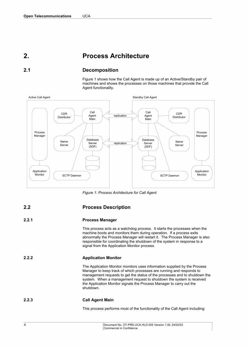
Figure 1 shows how the Call Agent is made up of an Active/Standby pair of machines and shows the processes on those machines that provide the Call Agent functionality.
Active Call Agent Standby Call Agent
CDRDistributor
CallAgentMain
ProcessManager
SCTP Daemon
DatabaseServer(SDF)
NameServer
ApplicationMonitor
CDRDistributor
CallAgentMain
ProcessManager
SCTP Daemon
DatabaseServer(SDF)
NameServer
ApplicationMonitor
replication
replication
Figure 1: Process Architecture for Call Agent
2.2 Process Description
2.2.1 Process Manager
This process acts as a watchdog process. It starts the processes when the machine boots and monitors them during operation. If a process exits abnormally the Process Manager will restart it. The Process Manager is also responsible for coordinating the shutdown of the system in response to a signal from the Application Monitor process.
2.2.2 Application Monitor
The Application Monitor monitors uses information supplied by the Process Manager to keep track of which processes are running and responds to management requests to get the status of the processes and to shutdown the system. When a management request to shutdown the system is received the Application Monitor signals the Process Manager to carry out the shutdown.
2.2.3 Call Agent Main
This process performs most of the functionality of the Call Agent including:
8 Document No. OT-PRD.UCA.HLD.005 Version 1.0b 24/02/03 Commercial in Confidence
Open Telecommunications UCA
• Protocol stacks for ISUP, SIP, MGCP, etc.
• Call handling
• Supplementary services
• OAM functions such as Configuration, Alarms, and Statistics
The Call Agent Main process replicates call state information between the active and standby machines to allow the standby machine to take over active calls in the event of a failover.
2.2.4 CDR Distributor
The CDR Distributor process connects to both of the Call Agent Main processes (one on each machine). As calls are initiated and terminated, the Call Agent Main processes sends updates to the CDR Distributor process so that it can generate CDRs in XML format into local files. CDRs are generated when calls are initiated and when they are torn down. In addition if a call is active for a long period the CDR Distributor will generate a CDR periodically (e.g. every hour) depending on the period it is configured with.
2.2.5 SDF Database Server
The SDF Database is used by the Call Agent as a persistent store for configuration information. The SDF database is used to provide a replicated database across both machines. Loss of either machine does not then impact the availability of the database.
2.2.6 Name Server
The Name Server process is used by CORBA clients (e.g. the MMI client) to locate the server objects in order to perform management requests such as updating the configuration data.
The Name Server listens for advertisements from the Call Agent about server objects and their CORBA addresses and keeps track of which objects are available under what name and what their address is. Clients can then connect to the Name Server to get the address of a particular named object they are interested in.
2.2.7 SCTP Daemon
The SCTP protocol requires a raw IP socket. Raw sockets are only available to processes running as “root”. Since we don’t really want the Call Agent to run as “root” we provide an SCTP daemon that runs as root and opens the raw socket. Client processes (such as the Call Agent) can then connect to the SCTP daemon using a normal TCP socket and use the daemon to send and receive SCTP messages on their behalf.
Document No. OT-PRD.UCA.HLD.005 Version 1.0b 24/02/03 Commercial in Confidence
9
Open Telecommunications UCA
3. Thread Architecture
3.1 Decomposition
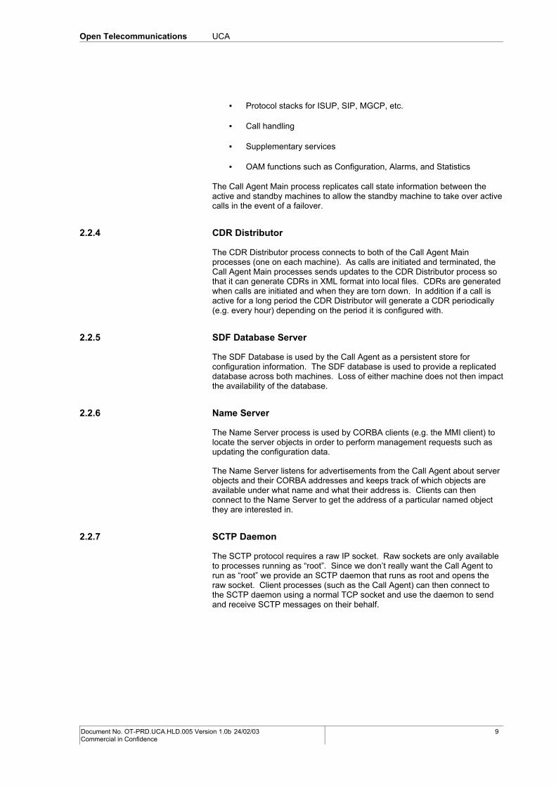
This section shows how the UCA Main is broken down into multiple threads.
UCA Main
Circuit Managment
OAM
to SDFServer
Call Handling
CCF
ISUPCCF
Supp.Services
BCM
SIPCCF
SDF ClientInterface
x
PDM
TimerManager
x
alarms,statistics
managementrequests/responses
ISUPCM
TrilliumISUP
Interface
TrilliumISUP
dispatcherx
VM
MGCP
MegacoAdaptor
MegacoStack
Redundancy
to SCTPDaemon
to MediaGateways
2
replication
TrilliumManagement
3
Legend:
thread
message flowbetween threads
communicationpath out of process
n n threads
x configurable ordynamic number of
threads
direct callsbetween modules
NA
M3UA 2
SCTP
DynamicSoftSIP
Stack
SIPAdaptor
to AdjacentCall Agent
SIPRM
Figure 2: UCA Thread Model
Figure 2 shows the main threads within the UCA Main process. It shows how the messages flow between the threads, concentrating on the message flows required for call handling.
10 Document No. OT-PRD.UCA.HLD.005 Version 1.0b 24/02/03 Commercial in Confidence
Open Telecommunications UCA
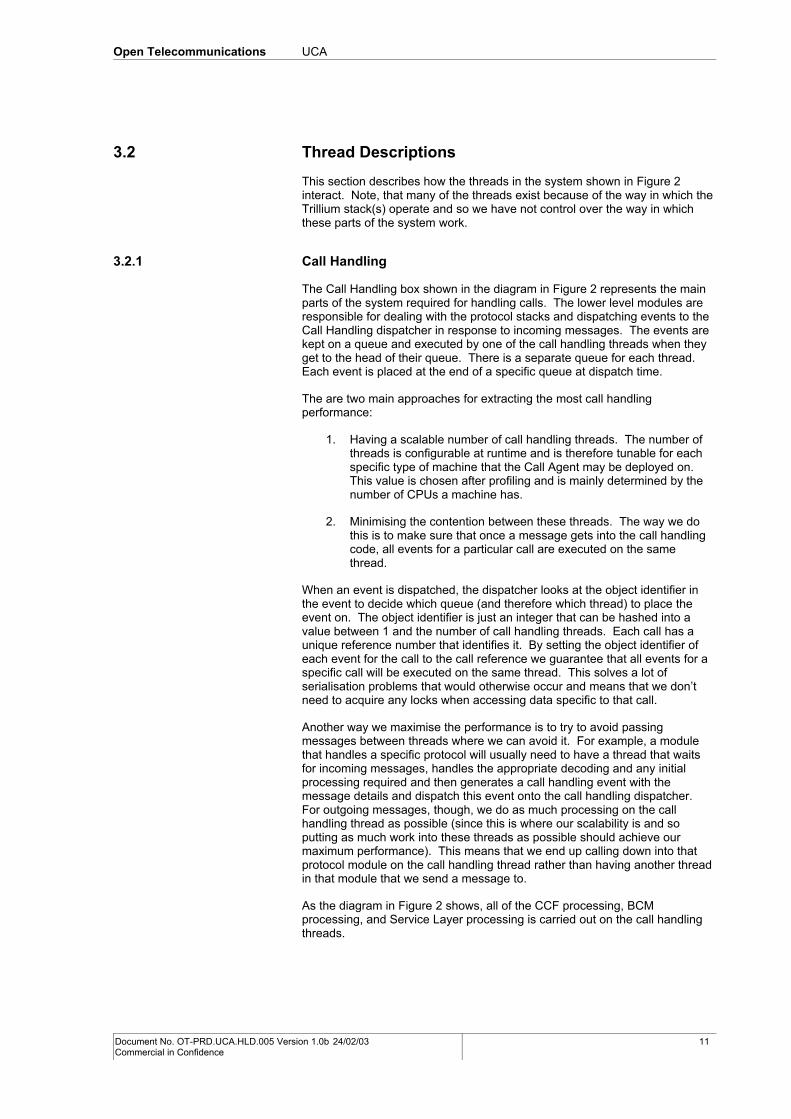
3.2 Thread Descriptions
This section describes how the threads in the system shown in Figure 2 interact. Note, that many of the threads exist because of the way in which the Trillium stack(s) operate and so we have not control over the way in which these parts of the system work.
3.2.1 Call Handling
The Call Handling box shown in the diagram in Figure 2 represents the main parts of the system required for handling calls. The lower level modules are responsible for dealing with the protocol stacks and dispatching events to the Call Handling dispatcher in response to incoming messages. The events are kept on a queue and executed by one of the call handling threads when they get to the head of their queue. There is a separate queue for each thread. Each event is placed at the end of a specific queue at dispatch time.
The are two main approaches for extracting the most call handling performance:
1. Having a scalable number of call handling threads. The number of threads is configurable at runtime and is therefore tunable for each specific type of machine that the Call Agent may be deployed on. This value is chosen after profiling and is mainly determined by the number of CPUs a machine has.
2. Minimising the contention between these threads. The way we do this is to make sure that once a message gets into the call handling code, all events for a particular call are executed on the same thread.
When an event is dispatched, the dispatcher looks at the object identifier in the event to decide which queue (and therefore which thread) to place the event on. The object identifier is just an integer that can be hashed into a value between 1 and the number of call handling threads. Each call has a unique reference number that identifies it. By setting the object identifier of each event for the call to the call reference we guarantee that all events for a specific call will be executed on the same thread. This solves a lot of serialisation problems that would otherwise occur and means that we don’t need to acquire any locks when accessing data specific to that call.
Another way we maximise the performance is to try to avoid passing messages between threads where we can avoid it. For example, a module that handles a specific protocol will usually need to have a thread that waits for incoming messages, handles the appropriate decoding and any initial processing required and then generates a call handling event with the message details and dispatch this event onto the call handling dispatcher. For outgoing messages, though, we do as much processing on the call handling thread as possible (since this is where our scalability is and so putting as much work into these threads as possible should achieve our maximum performance). This means that we end up calling down into that protocol module on the call handling thread rather than having another thread in that module that we send a message to.
As the diagram in Figure 2 shows, all of the CCF processing, BCM processing, and Service Layer processing is carried out on the call handling threads.
Document No. OT-PRD.UCA.HLD.005 Version 1.0b 24/02/03 Commercial in Confidence
11
Open Telecommunications UCA
3.2.2 SCTP
The SCTP module sets up a TCP connection to the SCTP daemon that it uses for sending and receiving SCTP messages. It also has a queue that the M3UA layer uses for outgoing messages.
The SCTP module has its own reactor thread that waits for both outgoing messages in the queue to write to the socket and for incoming messages from the socket that it sends to the M3UA layer above it.
3.2.3 M3UA
The M3UA module has a queue of incoming messages that the SCTP thread puts messages into and a Trillium queue of outgoing messages that need to be sent out.
There is a reactor thread that takes the incoming messages from SCTP and generates Trillium ISUP messages (assuming that it is an ISUP message) that are sent to the Trillium ISUP thread.
Another thread waits on the Trillium queue of outgoing messages and when a message arrives it formats it appropriately and sends it down to the SCTP layer.
3.2.4 Trillium ISUP
Within the Trillium stack there is a thread dedicated to doing the ISUP processing. It receives messages from the lower M3UA layer and from the application layer above and handles all of the state associated with the ISUP circuits.
3.2.5 Trillium ISUP Interface
This module (also known as the Trillium ISUP Wrapper) provides the interface to Trillium ISUP. It translates requests from call handling into Trillium messages and sends them down to the Trillium ISUP thread. This is all done on the call handling thread.
It has a dedicated thread for receiving messages from Trillium. It takes the Trillium messages and if they are call related, translates them into call handling events that are dispatched on to the appropriate call handling thread. If they are management messages (e.g. block, unblock, etc.) they are translated into events and sent to the ISUP CM thread.
3.2.6 Number Analysis
Number Analysis (NA) has no threads of its own. All number analysis occurs on the call handling thread of the call for which the number is being analysed. All MMI interactions occur on the requesting MMI thread.
3.2.7 ISUP CM
The ISUP Circuit Management module keeps track of the state of the ISUP circuits. It accepts management requests such as block/unblock from MMI commands (or equivalent), from VM, and as ISUP messages from another switch. The requests are converted into events and executed by a dedicated ISUP CM thread.
12 Document No. OT-PRD.UCA.HLD.005 Version 1.0b 24/02/03 Commercial in Confidence
Open Telecommunications UCA
When a management request (such as a reset) requires call handling to be notified it dispatches an appropriate event to the relevant call handling thread.
3.2.8 SIP RM
The SIP Route Management module keeps track of the state of the SIP routes. It has no threads of its own. It accepts management requests such as maintenance block/unblock from MMI commands (on MMI threads). It accepts hardware block notifications from the SIP adaptor, on SIP Stack threads. It is used by SIP CCF, on a call handling thread, to acquire a dialplan for an incoming SIP route and to acquire an outgoing SIP Route.
3.2.9 VM/MGCP/MegacoAdaptor
All outgoing MGCP/Megaco requests are processed on the thread making the request. This is usually one of the call handling threads but certain management requests mean that requests will also come from ISUP CM (e.g. on the reset of a circuit, ISUP CM will tell VM to end the call on the associated endpoint).
In MGCP, a dedicated thread exists that waits on the MGCP socket for incoming messages and then processes them. Incoming messages will usually be a response to an outgoing request in which case the receiver thread will generate an event for the response and dispatch it back to the thread that the original outgoing request was made on. It is also possible to receive Notifys and gateway initiated Deletes that will also be dispatched to the appropriate call handling thread.
Similarly, in the Megaco Adaptor, all outgoing requests are processed on the CCF thread that is making the request. All incoming messages are received on the Megaco stack thread and re-dispatched onto the thread that the original outgoing request was made on. Incoming asynchronous Megaco messages relating to calls (e.g. Notifys) will also be re-dispatched.
In the event of an unrecoverable error or when a gateway is shutdown or started, VM will generate an event for ISUP Circuit Management to block or unblock the relevant circuits and dispatch the event to the ISUP CM thread.
3.2.10 SIP Adaptor
The SIP adaptor layer acts as an adaptor between SIP CCF and the DynamicSoft SIP stack. For outgoing SIP requests (to adjacent Call Agents), all processing in the SIP adaptor occurs on the thread making the request. For processing of incoming responses and incoming requests, the SIP adaptor uses the SIP stack worker threads to receive the messages and re-dispatches them onto the thread that is doing the call handling for the call associated with the message.
SIP Adaptor also has Timer threads, which it uses to issue periodic registration requests to adjacent Call Agents, for heartbeating purposes. On receipt of registration refusal or failure on a SIP Stack thread, it notifies SIP RM of the failure.
3.2.11 DynamicSoft SIP Stack
The DynamicSoft SIP Stack uses the thread making the request to send the request. It receives all incoming messages on a management thread and then dispatches each message onto one of a pool of worker threads for further processing by both the SIP Stack and the SIP Adaptor.
Document No. OT-PRD.UCA.HLD.005 Version 1.0b 24/02/03 Commercial in Confidence
13
Open Telecommunications UCA
3.2.12 Trillium TUCL
The Trillium TUCL layer handles all Trillium protocols that are built on top of IP. For the Call Agent this is just H.323. It is supposed to provide an abstraction that hides the whether the underlying transport is TCP or UDP.
There are two threads in the Trillium TUCL layer. One thread is the listener thread and listens for incoming TCP connections that indicate new incoming H.323 calls. The other thread receives messages from the Trillium H.323 and writes them out the appropriate TCP socket as well as reading data from the socket and sending the appropriate messages to the Trillium H.323 thread.
3.2.13 Trillium Management
There are three threads that run as part of Trillium and provide all of the Trillium Management functionality. This functionality consists of configuration and startup coordination as well as ISUP redundancy.
To provide redundancy for ISUP calls the Trillium stack needs to synchronise state information with the standby instance of the stack. It provides a hook that we need to implement to transport the synchronisation messages between the active and standby machines. Our implementation uses functionality provided in the Redundancy module as the transport mechanism.
There is also functionality provided to allow us to tell the stack when to go standby and active.
3.2.14 Redundancy
This module consists of Redundancy, Redundancy Management, and Trillium Redundancy.
The Redundancy package provides a transport mechanism that operates over a redundant pair of ethernet interfaces to communicate with its partner on the other machine in the pair. It uses heartbeats to track the state of the other Call Agent and provides a call back mechanism for anyone interested in the state changes (e.g. Standby to Active).
Packages that want to synchronise state information between the active and standby Call Agents register with the Redundancy package and when messages arrive they are dispatched to the appropriate package. This will either be call handling synchronisation data that will be dispatched in an event to one of the call handling threads or Trillium Redundancy data that is then sent to the appropriate Trillium Management thread.
One thread in the Redundancy module receives messages from the other Call Agent and dispatches the messages to the appropriate recipient. Some of these messages are actually intended for the Redundancy module itself (e.g. heartbeat messages) and so another thread exists to receive the events generated by the receive thread when the destination is the Redundancy module.
3.2.15 Timer Manager
A Timer Manager thread exists to provide timeout functionality. Whenever timers are required, a timer is created and attached to a specific event. When the timer expires (if it hasn’t been cancelled), the Timer Manager thread dispatches the event to the appropriate destination thread.
14 Document No. OT-PRD.UCA.HLD.005 Version 1.0b 24/02/03 Commercial in Confidence
Open Telecommunications UCA
3.2.16 OAM
There are many threads that are used to provide the OAM functionality including:
• The TAO ORB uses a configurable number of threads for receiving and executing CORBA requests.
• A number of threads are used for inter-process and intra-process communications to implement Alarm Management and Statistics functionality.
• Threads are also used to periodically advertise the names and CORBA addresses of all of the management objects in the system.
3.2.17 PDM
The Persistent Data Management (PDM) module provides a way for other parts of the system to have persistent configuration information. It caches all information in memory and also stores the data persistently in a database. It is designed to operate in a distributed application where any process on any machine can be making updates. For the Call Agent, this means that when changes are made by the active machine, the changes are transparently replicated to the standby machine.
PDM uses a thread to periodically query the database for changes that have occurred so that it can update its in-memory cache.
3.2.18 SDF Client Interface
The implementation of PDM used on the Call Agent uses an SDF database back end as its persistent store. The client interface for the SDF uses a number of threads to provide an asynchronous interface to the database server process.
Document No. OT-PRD.UCA.HLD.005 Version 1.0b 24/02/03 Commercial in Confidence
15
Open Telecommunications UCA
4. UCA Sequence DiagramsThis section provides some sequence diagrams that describe how UCA subsystems interact under various operational scenarios.
4.1 Call Handling
This section presents some sequence diagrams for UCA call handling.
4.1.1 ISUP/SIP Call
SCTP M3UA Trillium ISUP Trillium ISUP Interface ISUP CCF ISUP CM NABCM SIP Adaptor SIP StackSIP RM
DATA()
DATA()
IAM()
IAM()
IAM()
newBCSM()
getDialPlanFromRoute()
getOutgoingRouteIds()
getSIPOutgoingRoute()
createOBCSM()
sendInvite()
sendInvite()
INVITE()
SIP CCF
createTBCSM()
newBCSM()
analysedInfo()
VM MGCP
createConnection()
CRCX()
CRCX()
MGCP 200 OK()
OK()
getSession()
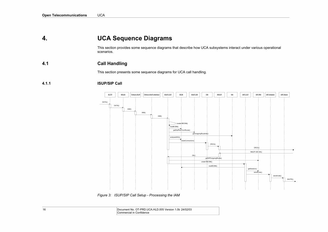
Figure 3: ISUP/SIP Call Setup - Processing the IAM
16 Document No. OT-PRD.UCA.HLD.005 Version 1.0b 24/02/03 Commercial in Confidence
Open Telecommunications UCA
This section describes the behaviour of a UCA that is acting as the originating UCA for a call which originates in the GSTN and is routed (via SIP as transit protocol) to an adjacent Call Agent. Figure 3 above shows how UCA receives an IAM, analyses the Called Party Number, sets up the media path for the originating side of the call, chooses an outgoing SIP route and issues a SIP INVITE to an adjacent Call Agent or SIP Application Server.
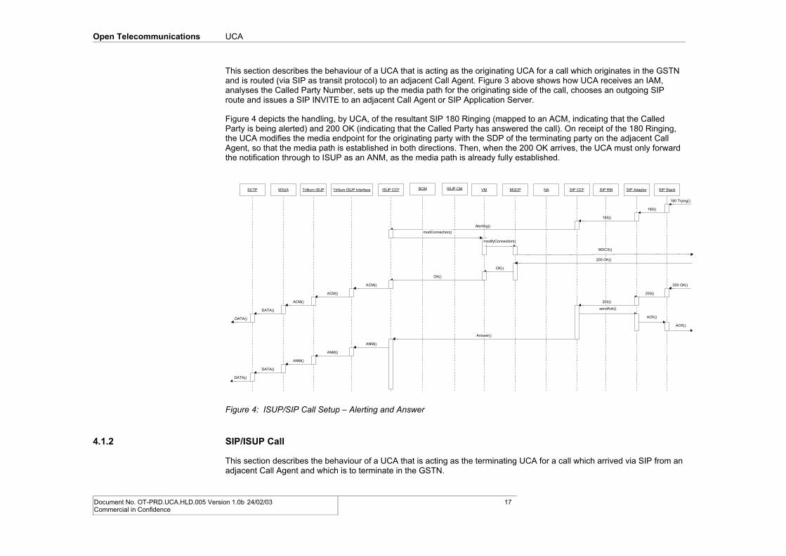
Figure 4 depicts the handling, by UCA, of the resultant SIP 180 Ringing (mapped to an ACM, indicating that the Called Party is being alerted) and 200 OK (indicating that the Called Party has answered the call). On receipt of the 180 Ringing, the UCA modifies the media endpoint for the originating party with the SDP of the terminating party on the adjacent Call Agent, so that the media path is established in both directions. Then, when the 200 OK arrives, the UCA must only forward the notification through to ISUP as an ANM, as the media path is already fully established.
SCTP M3UA Trillium ISUP Trillium ISUP Interface ISUP CCF ISUP CM NABCM SIP Adaptor SIP StackSIP RM
180 Trying()
180()
SIP CCF
180()
Alerting()
ACM()
ACM()
ACM()
DATA()
DATA()
VM MGCP
OK()
modConnection()
modifyConnection()
200 OK()
OK()
MDCX()
200 OK()
200()
200()
Answer()
ANM()
ANM()
ANM()
DATA()
DATA()
sendAck()
ACK()
ACK()
Figure 4: ISUP/SIP Call Setup – Alerting and Answer
4.1.2 SIP/ISUP Call
This section describes the behaviour of a UCA that is acting as the terminating UCA for a call which arrived via SIP from an adjacent Call Agent and which is to terminate in the GSTN.
Document No. OT-PRD.UCA.HLD.005 Version 1.0b 24/02/03 Commercial in Confidence
17
Open Telecommunications UCA
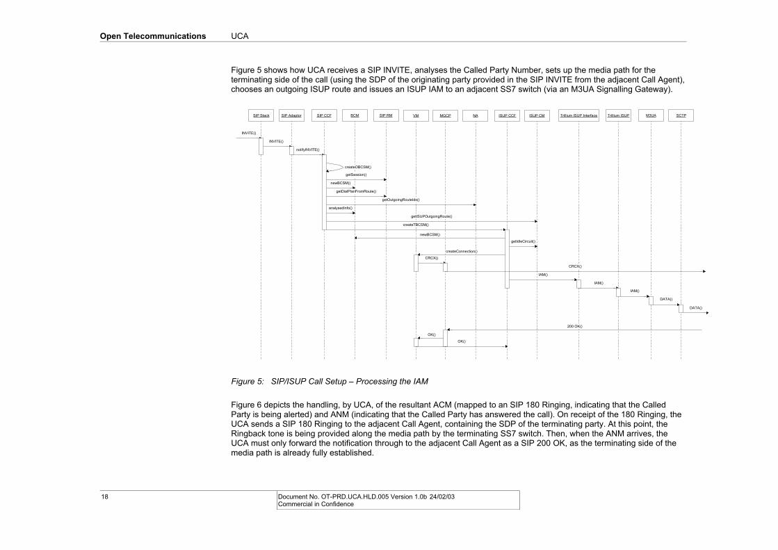
Figure 5 shows how UCA receives a SIP INVITE, analyses the Called Party Number, sets up the media path for the terminating side of the call (using the SDP of the originating party provided in the SIP INVITE from the adjacent Call Agent), chooses an outgoing ISUP route and issues an ISUP IAM to an adjacent SS7 switch (via an M3UA Signalling Gateway).
SCTPM3UATrillium ISUPTrillium ISUP InterfaceISUP CCF ISUP CMNABCMSIP AdaptorSIP Stack SIP RMSIP CCF VM MGCP
INVITE()
INVITE()
notifyINVITE()
createOBCSM()
getSession()
newBCSM()
getDialPlanFromRoute()
getOutgoingRouteIds()
getISUPOutgoingRoute()
createTBCSM()
newBCSM()
analysedInfo()
getIdleCircuit()
createConnection()
CRCX()
CRCX()
IAM()
IAM()
IAM()
DATA()
200 OK()
OK()
OK()
DATA()
Figure 5: SIP/ISUP Call Setup – Processing the IAM
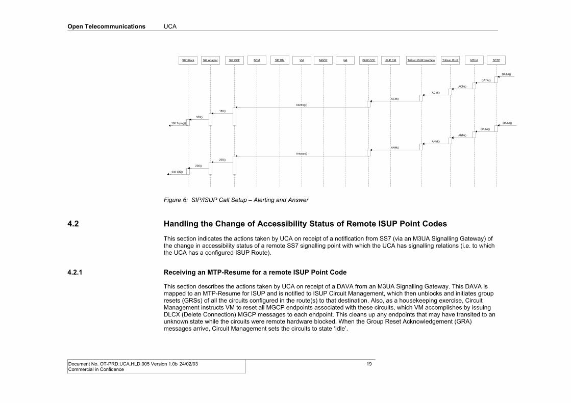
Figure 6 depicts the handling, by UCA, of the resultant ACM (mapped to an SIP 180 Ringing, indicating that the Called Party is being alerted) and ANM (indicating that the Called Party has answered the call). On receipt of the 180 Ringing, the UCA sends a SIP 180 Ringing to the adjacent Call Agent, containing the SDP of the terminating party. At this point, the Ringback tone is being provided along the media path by the terminating SS7 switch. Then, when the ANM arrives, the UCA must only forward the notification through to the adjacent Call Agent as a SIP 200 OK, as the terminating side of the media path is already fully established.
18 Document No. OT-PRD.UCA.HLD.005 Version 1.0b 24/02/03 Commercial in Confidence
Open Telecommunications UCA
SCTPM3UATrillium ISUPTrillium ISUP InterfaceISUP CCF ISUP CMNABCMSIP AdaptorSIP Stack SIP RMSIP CCF VM MGCP
DATA()
DATA()
ACM()
ACM()
ACM()
Alerting()
180()
180()
180 Trying() DATA()
DATA()
ANM()
ANM()
ANM()
Answer()
200()
200()
200 OK()
Figure 6: SIP/ISUP Call Setup – Alerting and Answer
4.2 Handling the Change of Accessibility Status of Remote ISUP Point Codes
This section indicates the actions taken by UCA on receipt of a notification from SS7 (via an M3UA Signalling Gateway) of the change in accessibility status of a remote SS7 signalling point with which the UCA has signalling relations (i.e. to which the UCA has a configured ISUP Route).
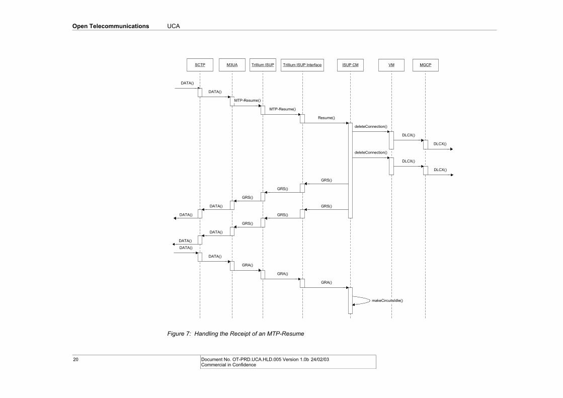
4.2.1 Receiving an MTP-Resume for a remote ISUP Point Code
This section describes the actions taken by UCA on receipt of a DAVA from an M3UA Signalling Gateway. This DAVA is mapped to an MTP-Resume for ISUP and is notified to ISUP Circuit Management, which then unblocks and initiates group resets (GRSs) of all the circuits configured in the route(s) to that destination. Also, as a housekeeping exercise, Circuit Management instructs VM to reset all MGCP endpoints associated with these circuits, which VM accomplishes by issuing DLCX (Delete Connection) MGCP messages to each endpoint. This cleans up any endpoints that may have transited to an unknown state while the circuits were remote hardware blocked. When the Group Reset Acknowledgement (GRA) messages arrive, Circuit Management sets the circuits to state ‘Idle’.
Document No. OT-PRD.UCA.HLD.005 Version 1.0b 24/02/03 Commercial in Confidence
19
Open Telecommunications UCA
SCTP M3UA Trillium ISUP Trillium ISUP Interface ISUP CM VM MGCP
DATA()
DATA()
MTP-Resume()
MTP-Resume()
Resume()
deleteConnection()
DLCX()
DLCX()
deleteConnection()
DLCX()
DLCX()
GRS()
GRS()
GRS()
DATA()
DATA()
GRS()
GRS()
GRS()
DATA()
DATA()
GRA()
DATA()
DATA()
GRA()
GRA()
makeCircuitsIdle()
Figure 7: Handling the Receipt of an MTP-Resume
20 Document No. OT-PRD.UCA.HLD.005 Version 1.0b 24/02/03 Commercial in Confidence
Open Telecommunications UCA
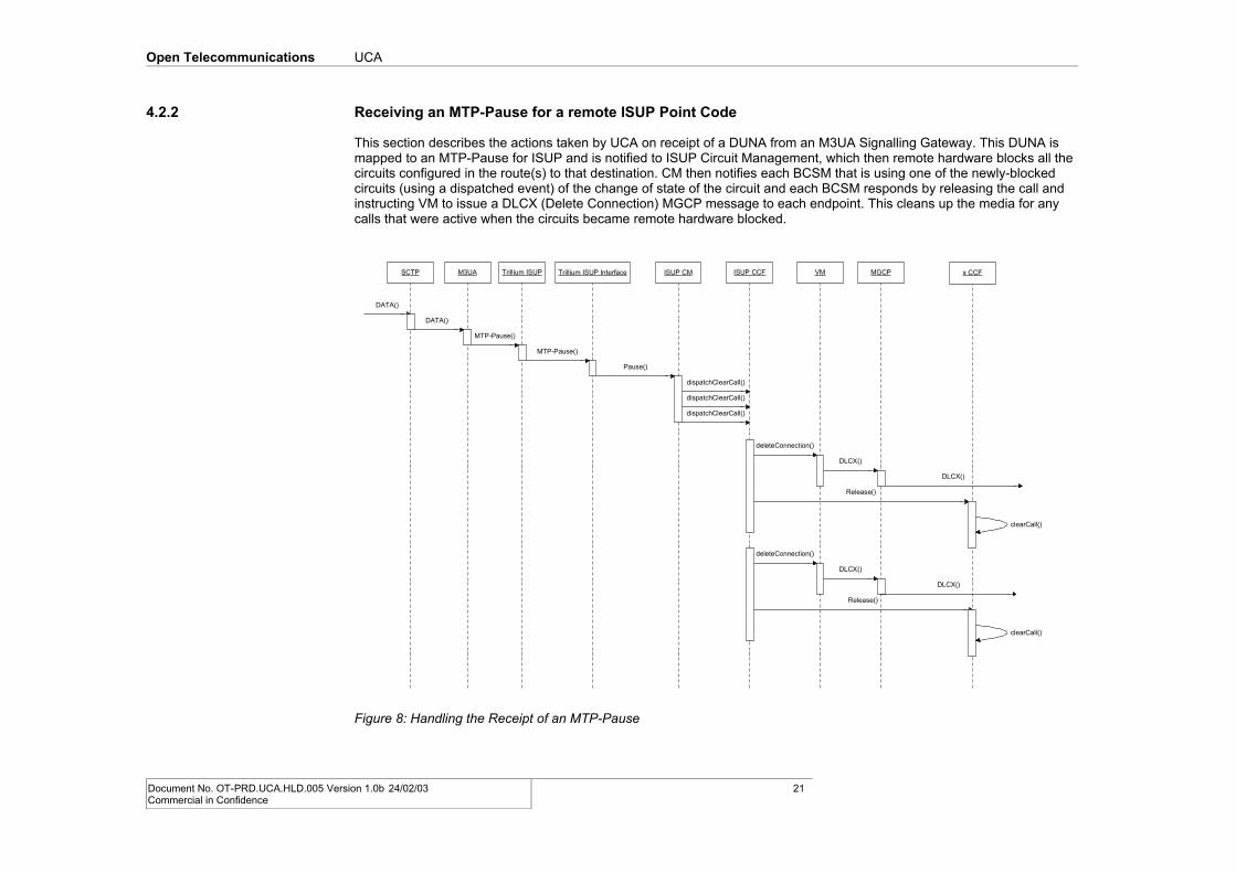
4.2.2 Receiving an MTP-Pause for a remote ISUP Point Code
This section describes the actions taken by UCA on receipt of a DUNA from an M3UA Signalling Gateway. This DUNA is mapped to an MTP-Pause for ISUP and is notified to ISUP Circuit Management, which then remote hardware blocks all the circuits configured in the route(s) to that destination. CM then notifies each BCSM that is using one of the newly-blocked circuits (using a dispatched event) of the change of state of the circuit and each BCSM responds by releasing the call and instructing VM to issue a DLCX (Delete Connection) MGCP message to each endpoint. This cleans up the media for any calls that were active when the circuits became remote hardware blocked.
SCTP M3UA Trillium ISUP Trillium ISUP Interface ISUP CM VM MGCP
DATA()
DATA()
MTP-Pause()
MTP-Pause()
Pause()
dispatchClearCall()
DLCX()
DLCX()
deleteConnection()
ISUP CCF x CCF
Release()
clearCall()
DLCX()
DLCX()
Release()
clearCall()
deleteConnection()
dispatchClearCall()
dispatchClearCall()
Figure 8: Handling the Receipt of an MTP-Pause
Document No. OT-PRD.UCA.HLD.005 Version 1.0b 24/02/03 Commercial in Confidence
21
Open Telecommunications UCA
A. Reference Information
A.1 References
0
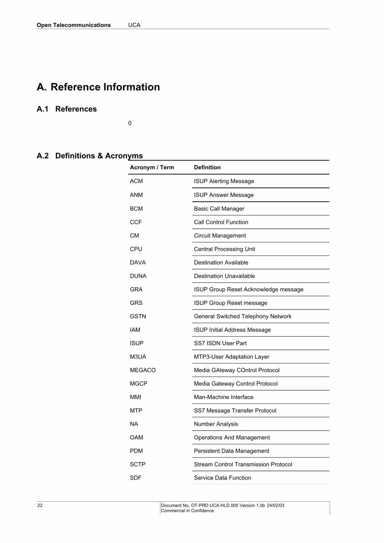
A.2 Definitions & Acronyms
Acronym / Term Definition
ACM ISUP Alerting Message
ANM ISUP Answer Message
BCM Basic Call Manager
CCF Call Control Function
CM Circuit Management
CPU Central Processing Unit
DAVA Destination Available
DUNA Destination Unavailable
GRA ISUP Group Reset Acknowledge message
GRS ISUP Group Reset message
GSTN General Switched Telephony Network
IAM ISUP Initial Address Message
ISUP SS7 ISDN User Part
M3UA MTP3-User Adaptation Layer
MEGACO Media GAteway COntrol Protocol
MGCP Media Gateway Control Protocol
MMI Man-Machine Interface
MTP SS7 Message Transfer Protocol
NA Number Analysis
OAM Operations And Management
PDM Persistent Data Management
SCTP Stream Control Transmission Protocol
SDF Service Data Function
22 Document No. OT-PRD.UCA.HLD.005 Version 1.0b 24/02/03 Commercial in Confidence
Open Telecommunications UCA
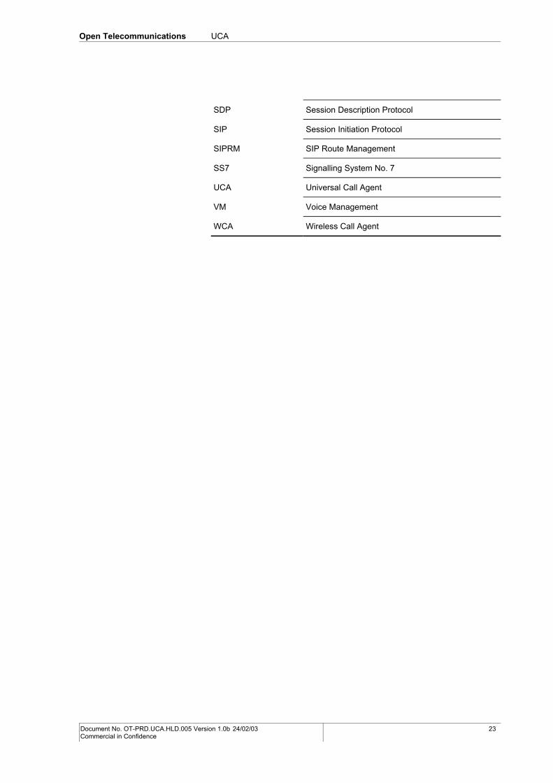
SDP Session Description Protocol
SIP Session Initiation Protocol
SIPRM SIP Route Management
SS7 Signalling System No. 7
UCA Universal Call Agent
VM Voice Management
WCA Wireless Call Agent
Document No. OT-PRD.UCA.HLD.005 Version 1.0b 24/02/03 Commercial in Confidence
23


