Embed Size (px)
Citation preview

Pratt & Whitney Engine Services, Inc.249 Vanderbilt AveNorwood, MA 02062
249 Vanderbilt Avenue, Norwood, MA 02062, Phone 781-762-8600, Fax 781-762-2287
ADAS+Installation Manual
ADAS-G-010-1
Manual Number ADAS-G-010-1
Preparation Date: November 14, 2002 Prepared By: D Desaulnier
Release Date: December 1, 2002 S Sackos, Manager of Manufacturing Services
Revision Date: February 24, 2009 D Fetherston, Manager of Engineering
Revision Ltr: G
Pages: 44
Approvals:

P&W ENGINE SERVICES, INC. ADAS+ ADAS-G-010-1Fixed Wing Aircraft Installation Manual
ADAS-G-010-1 Pratt & Whitney Engine Services, Inc. Proprietary - i -
PREFACE
Disclaimer
Like all instrumentation, the Pratt & Whitney Engine Services, Inc. ADAS+ requires knowledgeable interpretation by the pilot.Any recommendations and operating procedures contained in this manual shall not supersede the Aircraft or Enginemanufacturer recommendations, operating procedures, or limits. The Pratt & Whitney Engine Services, Inc. ADAS+ shouldnot be used as a primary guide monitoring the Aircraft and Engine manufacturers operating limits. Pratt & Whitney EngineServices, Inc. is not liable for any damages resulting from the use of this product.
Proprietary Information Notice
This manual contains proprietary information that is protected by copyright, and all rights are reserved. No portion of thisdocument may be copied, photocopied, reproduced by any means, or translated into another language without the priorwritten permission of P&W Engine Services.
P&W ENGINE SERVICES, INC. ADAS+ ADAS-G-010-1Fixed Wing Aircraft Installation Manual
ADAS-G-010-1 Pratt & Whitney Engine Services, Inc. Proprietary - ii -
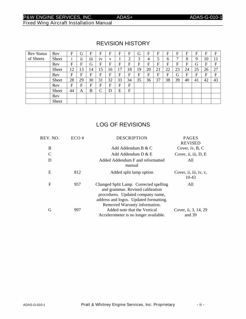
REVISION HISTORY
Rev F G F F F F F G F F F F F F F FRev Statusof Sheets Sheet i ii iii iv v 1 2 3 4 5 6 7 8 9 10 11
Rev F F G F F F F F F F F F F G F FSheet 12 13 14 15 16 17 18 19 20 21 22 23 24 25 26 27Rev F F F F F F F F F F F G F F F FSheet 28 29 30 31 32 33 34 35 36 37 38 39 40 41 42 43Rev F F F F F F FSheet 44 A B C D E FRevSheet
LOG OF REVISIONS
REV. NO. ECO # DESCRIPTION PAGESREVISED
B Add Addendum B & C Cover, iv, B, C
C Add Addendum D & E Cover, ii, iii, D, E
D Added Addendum F and reformattedmanual
All
E 812 Added split lamp option Cover, ii, iii, iv, v,10-43
F 957 Changed Split Lamp. Corrected spellingand grammar. Revised calibration
procedures. Updated company name,address and logos. Updated formatting.
Removed Warranty information.
All
G 997 Added note that the VerticalAccelerometer is no longer available.
Cover, ii, 3, 14, 29and 39
P&W ENGINE SERVICES, INC. ADAS+ ADAS-G-010-1Fixed Wing Aircraft Installation Manual
ADAS-G-010-1 Pratt & Whitney Engine Services, Inc. Proprietary - iii -
TABLE OF CONTENTS
1 INTRODUCTION........................................................................................................................................... 21.1 Scope....................................................................................................................................................... 21.2 About This Manual ................................................................................................................................. 21.3 System Description ................................................................................................................................. 21.4 Unpacking the Equipment....................................................................................................................... 21.5 Parts List.................................................................................................................................................. 21.6 Weight and Balance ................................................................................................................................ 2
2 INSTALLATION AND MAINTENANCE PROCEDURES......................................................................... 22.1 Standard Practices-Airframe/Powerplant ................................................................................................ 2
2.1.1 Procedure for Wiring Connections.................................................................................................. 22.1.2 Wiring Splices ................................................................................................................................. 22.1.3 Maintenance .................................................................................................................................... 2
3 INSTALLATION - MECHANICAL.............................................................................................................. 23.1 System Processor .................................................................................................................................... 23.2 Cockpit Components ............................................................................................................................... 2
3.2.1 TREND Switch / Fault Lamp.......................................................................................................... 23.2.2 Engine/Trend Split Lamp Option.................................................................................................... 23.2.3 Download (COMM) Port ................................................................................................................ 2
3.3 Airframe Components ............................................................................................................................. 23.3.1 Circuit Breaker ................................................................................................................................ 23.3.2 Fuse (+28VDC)............................................................................................................................... 23.3.3 Outside Air Temperature (OAT) Probe........................................................................................... 23.3.4 Pitot/Static Pressure Transducers .................................................................................................... 23.3.5 Vertical Accelerometer ................................................................................................................... 23.3.6 Firewall/Pressure Bulkhead Feedthru ............................................................................................. 23.3.7 Discrete Aircraft Signals ................................................................................................................. 2
3.4 Engine Indicating Components ............................................................................................................... 23.4.1 Engine Temperature Sensors (T4, T4.5, ITT, EGT, MGT, TOT)................................................... 23.4.2 Engine N1 (Ng) Speed Sensor ........................................................................................................ 23.4.3 Engine N2 Speed Sensor ................................................................................................................. 23.4.4 Propeller (Np) Speed Sensor ........................................................................................................... 23.4.5 Engine Torque (Tq) Pressure .......................................................................................................... 2
4 INSTALLATION - ELECTRICAL ................................................................................................................ 24.1 Electrical Power ...................................................................................................................................... 2
4.1.1 J1 Harness (Power and Sensor Signals) .......................................................................................... 24.1.2 J2 Harness (Sensor Signals) ............................................................................................................ 24.1.3 J3 Harness (Sensor Signals) ............................................................................................................ 2
5 SYSTEM OPERATION OVERVIEW ........................................................................................................... 25.1 ADAS+ Functional Description .............................................................................................................. 2
5.1.1 Engine Run Logging ....................................................................................................................... 25.1.2 Cycle Logging ................................................................................................................................. 25.1.3 Event Monitoring and Time History Buffer.................................................................................... 25.1.4 Trend Monitoring ............................................................................................................................ 2
5.2 System Initialization and Lamp State Description .................................................................................. 25.3 System Modes ......................................................................................................................................... 25.4 Run Mode Description (States and Fault Lamp Display) ....................................................................... 2
5.4.1 Fault Lamp Display for Optional ENGINE/TREND Split Lamp ................................................... 2
P&W ENGINE SERVICES, INC. ADAS+ ADAS-G-010-1Fixed Wing Aircraft Installation Manual
ADAS-G-010-1 Pratt & Whitney Engine Services, Inc. Proprietary - iv -
6 SYSTEM CONFIGURATION AND CALIBRATION.................................................................................. 26.1 Definitions............................................................................................................................................... 26.2 Processor Configuration.......................................................................................................................... 2
6.2.1 Pre-Calibration Sensor Test ............................................................................................................ 26.3 Calibration of Optional Sensors .............................................................................................................. 26.4 Calibration Using Test Equipment .......................................................................................................... 26.5 Calibration Using Aircraft Cockpit Instruments ..................................................................................... 2
7 AIRCRAFT TESTING ................................................................................................................................... 27.1 Aircraft Ground Test ............................................................................................................................... 27.2 Aircraft Flight Test.................................................................................................................................. 27.3 Test Data Retrieval and Review.............................................................................................................. 27.4 Continued Airworthiness Instructions..................................................................................................... 2
8 SERVICE ........................................................................................................................................................ 28.1 Customer Support.................................................................................................................................... 2
9 SPECIFICATIONS ......................................................................................................................................... 29.1 System Specifications ............................................................................................................................. 29.2 SPECIFICATIONS FOR P&W ENGINE SERVICES SUPPLIED SENSORS .................................... 29.3 Interface Requirements For Aircraft Sensors.......................................................................................... 2
ADDENDUM A: ADAS+ Installation Manual for Cessna Caravan Model Series 208 ........................................BADDENDUM B: ADAS+ Installation Manual for Raytheon Model Series 90 ....................................................BADDENDUM C: ADAS+ Installation Manual for Raytheon Model Series 200, 300, & 1900 ............................BADDENDUM D: ADAS+ Installation Manual for Embraer Model EMB-110P1 and EMB-110P2 ....................BADDENDUM E: ADAS+ Installation Manual for Air Tractor Models AT-400, 400A, 402, 402A, 402B 501,502, 502A, 502B, 503, 503A, 602, 802, 802A........................................................................................................BADDENDUM F: ADAS+ Installation Manual for Pilatus Porter Model PC-6B & C Series................................B
P&W ENGINE SERVICES, INC. ADAS+ ADAS-G-010-1Fixed Wing Aircraft Installation Manual
ADAS-G-010-1 Pratt & Whitney Engine Services, Inc. Proprietary - v -
LIST OF FIGURES
FIGURE 1: TYPICAL ADAS+ ..................................................................................................................................................... 2FIGURE 2: SINGLE OR DUAL WIRE SPLICES............................................................................................................................... 2FIGURE 3: SHIELDED CONNECTION (OUTER HEAT-SHRINK TUBING NOT SHOWN).................................................................... 2FIGURE 4: PROCESSOR .............................................................................................................................................................. 2FIGURE 5: TYPICAL AVIONICS COMPARTMENT SHOCK MOUNT DETAIL ................................................................................... 2FIGURE 6: TYPICAL ENGINE COMPARTMENT SHOCK MOUNT DETAIL ...................................................................................... 2FIGURE 7: TREND SWITCH/FAULT LAMP................................................................................................................................. 2FIGURE 8: ENGINE/TREND SPLIT LAMP .................................................................................................................................. 2FIGURE 9: DOWNLOAD PORT .................................................................................................................................................... 2FIGURE 10: OAT PROBE ........................................................................................................................................................... 2FIGURE 11: PITOT TRANSDUCER ............................................................................................................................................... 2FIGURE 12: STATIC TRANSDUCER ............................................................................................................................................. 2FIGURE 13: VERTICAL ACCELEROMETER .................................................................................................................................. 2FIGURE 14: TORQUE TRANSDUCER ........................................................................................................................................... 2
LIST OF TABLES
TABLE 1: PITOT TRANSDUCER SPECIFICATIONS ....................................................................................................................... 2TABLE 2: STATIC TRANSDUCER SPECIFICATIONS ..................................................................................................................... 2TABLE 3: TORQUE TRANSDUCER SPECIFICATIONS ................................................................................................................... 2TABLE 4: VHF FREQUENCY TABLE .......................................................................................................................................... 2TABLE 5: ELECTROMAGNETIC COMPATIBILITY TEST TABLE.................................................................................................... 2TABLE 6: GROUND TEST DATA ................................................................................................................................................ 2TABLE 7: FLIGHT TEST DATA................................................................................................................................................... 2
REFERENCE DOCUMENTS
ADAS-G-260-1 “ADAS+ Instructions for Continued Airworthiness”MLP User’s Guide “P&W Engine Services Monitor Link Program”

P&W ENGINE SERVICES, INC. ADAS+ ADAS-G-010-1Fixed Wing Aircraft Installation Manual
ADAS-G-010-1 Pratt & Whitney Engine Services, Inc. Proprietary - 1 -
1 INTRODUCTION
Aircraft and engine maintenance procedures are critical to flight safety and lower operating costs. P&W EngineServices has developed an aircraft data acquisition system known as ADAS+ to perform three primaryfunctions:
Exceedance Event Recording: The ADAS+ can monitor critical engine parameters and record instanceswhere they have exceeded preset values (exceedances).
Engine Trend Monitoring: The ADAS+ can gather and store engine data samples for trend analysis.
Cockpit Indication: The ADAS+ can be configured to warn the pilot of a prior exceedance on start up orshutdown, and provide system self-test indication.
The ADAS+ enables the operator to control, quantify, and manage engine maintenance operations and reducedirect operating costs.
In its data acquisition role, ADAS+ is a passive receiver of information. It can be configured to record dataeither manually or automatically.
Manual Operation: The pilot can quickly record a dataset from all sensors by pressing a cockpit-mountedTREND switch.
Automatic Operation: The system may be configured to automatically record exceedance events andtrends. It may also be configured to record data samples when stable aircraft conditions are achieved. Theseconditions are configurable, and the data gathered may be used for engine trend analysis.
Retrieving Data: Collected data is accessed through a download serial port. Communication with theADAS+ is achieved through P&W Engine Services Monitor Link Program (MLP), which can be used todownload data and upload system configuration files. The MLP can also be used to assist maintenancepersonnel in performing system diagnostics, calibrations, and real-time live sensor display.
System Configuration: The ADAS+ system is shipped with a predefined set of software sensorconfigurations, exceedance event specifications, cycle specifications, and engine start/stop definitions.System configurations can be altered to reflect the customer’s operating environment or requirements.
P&W ENGINE SERVICES, INC. ADAS+ ADAS-G-010-1Fixed Wing Aircraft Installation Manual
ADAS-G-010-1 Pratt & Whitney Engine Services, Inc. Proprietary - 2 -
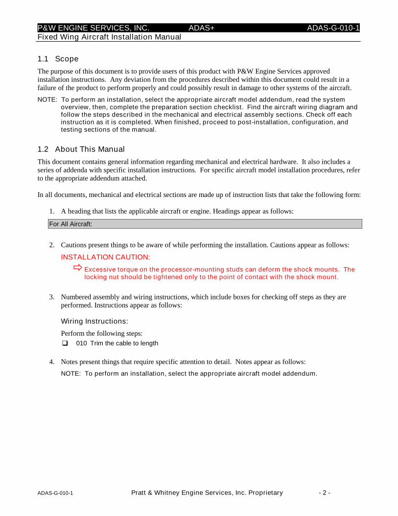
1.1 Scope
The purpose of this document is to provide users of this product with P&W Engine Services approvedinstallation instructions. Any deviation from the procedures described within this document could result in afailure of the product to perform properly and could possibly result in damage to other systems of the aircraft.
NOTE: To perform an installation, select the appropriate aircraft model addendum, read the systemoverview, then, complete the preparation section checklist. Find the aircraft wiring diagram andfollow the steps described in the mechanical and electrical assembly sections. Check off eachinstruction as it is completed. When finished, proceed to post-installation, configuration, andtesting sections of the manual.
1.2 About This Manual
This document contains general information regarding mechanical and electrical hardware. It also includes aseries of addenda with specific installation instructions. For specific aircraft model installation procedures, referto the appropriate addendum attached.
In all documents, mechanical and electrical sections are made up of instruction lists that take the following form:
1. A heading that lists the applicable aircraft or engine. Headings appear as follows:
For All Aircraft:
2. Cautions present things to be aware of while performing the installation. Cautions appear as follows:
INSTALLATION CAUTION:
Excessive torque on the processor-mounting studs can deform the shock mounts. Thelocking nut should be tightened only to the point of contact with the shock mount.
3. Numbered assembly and wiring instructions, which include boxes for checking off steps as they areperformed. Instructions appear as follows:
Wiring Instructions:
Perform the following steps:
010 Trim the cable to length
4. Notes present things that require specific attention to detail. Notes appear as follows:
NOTE: To perform an installation, select the appropriate aircraft model addendum.
P&W ENGINE SERVICES, INC. ADAS+ ADAS-G-010-1Fixed Wing Aircraft Installation Manual
ADAS-G-010-1 Pratt & Whitney Engine Services, Inc. Proprietary - 3 -
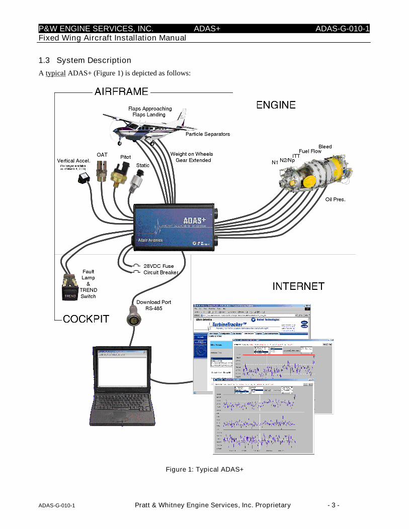
1.3 System Description
A typical ADAS+ (Figure 1) is depicted as follows:
Figure 1: Typical ADAS+
P&W ENGINE SERVICES, INC. ADAS+ ADAS-G-010-1Fixed Wing Aircraft Installation Manual
ADAS-G-010-1 Pratt & Whitney Engine Services, Inc. Proprietary - 4 -
1.4 Unpacking the Equipment
Carefully remove each component from the original shipping container. Place each component on a roll-awaycart or suitable workbench in the work area.
1.5 Parts List
Care must be taken when handling all parts and equipment. Before opening packages, perform an inventorycheck by comparing the receivables to the appropriate bill of materials.
1.6 Weight and Balance
Calculating weight and balance of the ADAS+ after installation is the responsibility of the installer. Althoughthe system weight is less than 11 pounds (excluding miscellaneous hardware not supplied with the kit – e.g.clamps, tie wraps etc…), P&W Engine Services suggests that the installer weigh each kit individually andrecord the weight prior to installation. During the installation, save all items that are not installed on the aircraft,for example: cable that has been trimmed to length and any plastic or paper bags that individual componentswere packaged in. After the completion of the installation, weigh all materials that were not installed on theaircraft. Subtract this weight from the weight of the kit prior to the installation. This will give you the totalsystem weight that is installed on the aircraft. For LRU weights and locations, refer to the addendum specific toyour aircraft application.
P&W ENGINE SERVICES, INC. ADAS+ ADAS-G-010-1Fixed Wing Aircraft Installation Manual
ADAS-G-010-1 Pratt & Whitney Engine Services, Inc. Proprietary - 5 -
2 INSTALLATION AND MAINTENANCE PROCEDURES
INSTALLATION CAUTION:
Use of any procedure (e.g. addendum) that does not apply to your specific applicationcould cause unnecessary damage to the aircraft and/or result in a system or productmalfunction.
2.1 Standard Practices-Airframe/Powerplant
Prior to installation, be sure that you have read the appropriate model addendum that applies to your specificinstallation. Review all manufacturer provided airframe and powerplant documentation in order to understandinstallation requirements and technical capability of the system.
NOTE: General wiring supplies (solder, crimp splices, heat shrink, tape, cable ties and cable tie holders,etc…) are not included with the installation kit.
Prior to installation, verify and follow each of the following instructions and guidelines:
1. All work to be done in accordance with FAA Advisory Circular 43.13-1B "Acceptable Methods,Techniques, and Practices - Aircraft Inspection and Repair" and with FAA Advisory Circular 43.13-2A"Acceptable Methods, Techniques and Practices - Aircraft Alterations"
2. Read all instructions completely before beginning any installation. Only qualified mechanics or avionicstechnicians shall perform the installation.
3. All aircraft systems interfacing with the P&W Engine Services ADAS+ must be checked for fullfunctionality before installation begins.
4. All illustrated mounting locations should be used as a general guide for mounting. Locations shown inillustrations may be altered to fit special individual installation requirements as needed, providedaccepted structural procedures and practices are followed.
5. Refer to the manufacturer’s manual for approved locations or cautions for clamping hoses and cables, ormodifying the aircraft structure.
2.1.1 Procedure for Wiring Connections
INSTALLATION CAUTION:
The ADAS+ cables have shields that connect to the processor chassis ground. Whenterminating the shielded harness at the airframe connection, these shields must betrimmed back and insulated to prevent possible shorting with the signal wires.
NOTE: Each cable is marked with a shrink on label near the end to indicate its connection. When youshorten the cable behind the label, be sure to re-label it.

P&W ENGINE SERVICES, INC. ADAS+ ADAS-G-010-1Fixed Wing Aircraft Installation Manual
ADAS-G-010-1 Pratt & Whitney Engine Services, Inc. Proprietary - 6 -
2.1.2 Wiring Splices
The use of Raychem™ hermetic style wire splices (Figure 2 and Figure 3) is recommended. When makingconnections between two shielded cables, the shields should also be maintained using Raychem™ or equivalentshield splices. The entire cable splice should be encased in heat shrink tubing when completed.
A general procedure for wire splices (See Figure 2 and Figure 3) is illustrated as follows:
RAYCHEM D-436-37
OR EQUIVALENT
Figure 2: Single or Dual Wire Splices
1. INSERT PREPARED CABLE
2. APPLY HEAT
RAYCHEM
S01-04-R
OR EQUIVALENT
3. SPLICE W IRE AND
SHIELD PIGTAIL
Figure 3: Shielded connection (Outer Heat-Shrink Tubing Not Shown)

P&W ENGINE SERVICES, INC. ADAS+ ADAS-G-010-1Fixed Wing Aircraft Installation Manual
ADAS-G-010-1 Pratt & Whitney Engine Services, Inc. Proprietary - 7 -
2.1.3 Maintenance
The P&W Engine Services ADAS+ has been designed with the latest solid-state technology. The onlycomponent that has a limited life span is the internal battery. This battery, under normal operating conditions, isexpected to last 10 years. If the battery is discharged, the processor must be returned to P&W Engine Servicesfor battery replacement.
The calibration of the system should remain within documented specifications under normal operation. It issuggested that operators initially monitor the calibration of the ADAS+ every other 100-hour inspection. If thecalibration does not change after 3 inspections the calibration check period can be increased to coincide with theplanned aircraft instrument schedule.
Care of the processor under normal operation consists of general cleaning and inspection for bracket andconnector security during every major engine or aircraft inspection. Refer to ADAS+ Instructions for ContinuedAirworthiness, ADAS-G-260-1.
Comments and findings should be forwarded to P&W Engine Services for inclusion into their continued productimprovement program.
In the event that the ADAS+ must be returned for service, contact the P&W Engine Services Help Desk for aReturned Material Authorization (RMA) number. When you receive the RMA number, include it in the packageaddress and ship it, postage and insurance prepaid, to the address listed below.
When shipping an item for service, please include a complete detailed description of the symptoms you areexperiencing. This will greatly assist our technicians in rapidly identifying the problem. After service, theprocessor will be returned to you or your dealer with the shipping prepaid.
Pratt & Whitney Engine Services, Inc.Help Desk249 Vanderbilt AvenueNorwood, MA 02062Phone: (781) 762-8600Fax: (781) 762-2287E-mail: [email protected]
P&W ENGINE SERVICES, INC. ADAS+ ADAS-G-010-1Fixed Wing Aircraft Installation Manual
ADAS-G-010-1 Pratt & Whitney Engine Services, Inc. Proprietary - 8 -
3 INSTALLATION - MECHANICAL
3.1 System Processor
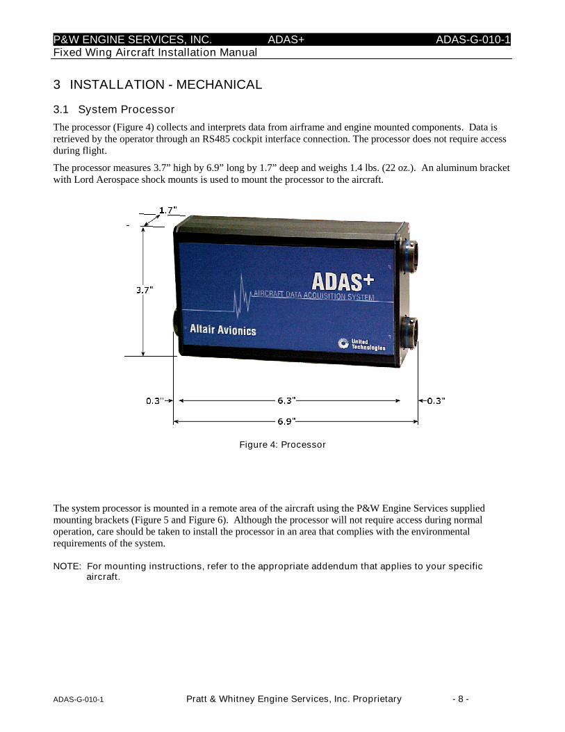
The processor (Figure 4) collects and interprets data from airframe and engine mounted components. Data isretrieved by the operator through an RS485 cockpit interface connection. The processor does not require accessduring flight.
The processor measures 3.7” high by 6.9” long by 1.7” deep and weighs 1.4 lbs. (22 oz.). An aluminum bracketwith Lord Aerospace shock mounts is used to mount the processor to the aircraft.
Figure 4: Processor
The system processor is mounted in a remote area of the aircraft using the P&W Engine Services suppliedmounting brackets (Figure 5 and Figure 6). Although the processor will not require access during normaloperation, care should be taken to install the processor in an area that complies with the environmentalrequirements of the system.
NOTE: For mounting instructions, refer to the appropriate addendum that applies to your specificaircraft.

P&W ENGINE SERVICES, INC. ADAS+ ADAS-G-010-1Fixed Wing Aircraft Installation Manual
ADAS-G-010-1 Pratt & Whitney Engine Services, Inc. Proprietary - 9 -
Figure 5: Typical Avionics Compartment Shock Mount Detail
Figure 6: Typical Engine Compartment Shock Mount Detail
P&W ENGINE SERVICES, INC. ADAS+ ADAS-G-010-1Fixed Wing Aircraft Installation Manual
ADAS-G-010-1 Pratt & Whitney Engine Services, Inc. Proprietary - 10 -
3.2 Cockpit Components
There are two components that must be mounted so that they are accessible. Following are the descriptions andfunctions of the cockpit components and indicators:
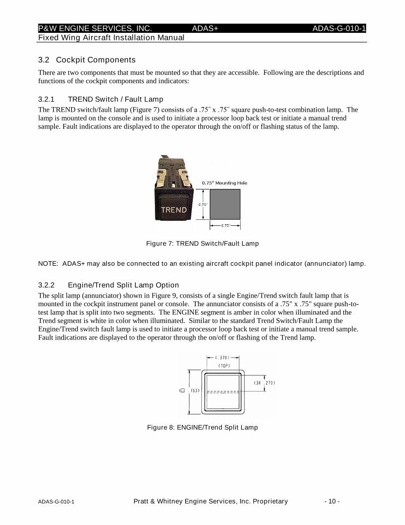
3.2.1 TREND Switch / Fault Lamp
The TREND switch/fault lamp (Figure 7) consists of a .75˝ x .75˝ square push-to-test combination lamp. Thelamp is mounted on the console and is used to initiate a processor loop back test or initiate a manual trendsample. Fault indications are displayed to the operator through the on/off or flashing status of the lamp.
Figure 7: TREND Switch/Fault Lamp
NOTE: ADAS+ may also be connected to an existing aircraft cockpit panel indicator (annunciator) lamp.
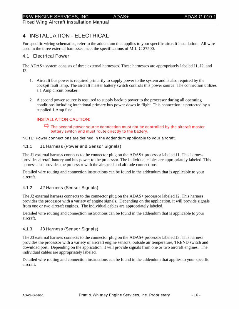
3.2.2 Engine/Trend Split Lamp Option
The split lamp (annunciator) shown in Figure 9, consists of a single Engine/Trend switch fault lamp that ismounted in the cockpit instrument panel or console. The annunciator consists of a .75" x .75" square push-to-test lamp that is split into two segments. The ENGINE segment is amber in color when illuminated and theTrend segment is white in color when illuminated. Similar to the standard Trend Switch/Fault Lamp theEngine/Trend switch fault lamp is used to initiate a processor loop back test or initiate a manual trend sample.Fault indications are displayed to the operator through the on/off or flashing of the Trend lamp.
Figure 8: ENGINE/Trend Split Lamp

P&W ENGINE SERVICES, INC. ADAS+ ADAS-G-010-1Fixed Wing Aircraft Installation Manual
ADAS-G-010-1 Pratt & Whitney Engine Services, Inc. Proprietary - 11 -
3.2.3 Download (COMM) Port
The COMM Port is used to interface with the processor. Data can be transferred and downloaded through thisport (Figure 9).
Figure 9: Download Port
NOTE: Installation instructions for each of the cockpit components can be found in the addendumspecific to your aircraft.

P&W ENGINE SERVICES, INC. ADAS+ ADAS-G-010-1Fixed Wing Aircraft Installation Manual
ADAS-G-010-1 Pratt & Whitney Engine Services, Inc. Proprietary - 12 -
3.3 Airframe Components
A description of airframe components as well as their function is described in the following:
3.3.1 Circuit Breaker
The 1 amp circuit breaker automatically interrupts the electrical circuit under abnormal conditions. Specificmounting and installation instructions can be found in the addendum applicable to your aircraft.
3.3.2 Fuse (+28VDC)
The 1 amp fuse is mounted in a remote location and automatically interrupts the electrical circuit underabnormal conditions. Specific mounting and installation instructions can be found in the addendum applicableto your aircraft.
3.3.3 Outside Air Temperature (OAT) Probe
The temperature probe (Figure 10) is mounted on the underside of the aircraft to provide the processor withOAT data. Specific mounting and installation instructions can be found in the addendum applicable to youraircraft.
Figure 10: OAT Probe
3.3.4 Pitot/Static Pressure Transducers
Airspeed and altitude are calculated by installing a 5 VDC, 0-3 PSID transducer and 0-15 PSIA transducer thatcan be mounted directly in-line with the existing pitot/static system. Illustrations in Figure 11 and Figure 12 aretypical representations of P&W Engine Services supplied Pitot/Static Transducers. Refer to Table 1 andTable 2 for transducer specifications.

P&W ENGINE SERVICES, INC. ADAS+ ADAS-G-010-1Fixed Wing Aircraft Installation Manual
ADAS-G-010-1 Pratt & Whitney Engine Services, Inc. Proprietary - 13 -
Figure 11: Pitot Transducer
Table 1: Pitot Transducer Specifications
Pressure Range 0-3 PSID
Supply Current 5mA Max. @ 5VDC
Supply Voltage 5.00 VDC
Output Voltage 0.5 – 4.5 VDC
Range 0 PSID (0 Knots) to 3.00 PSID (340 Knots)
Hysteresis &Repeatability
+/- .05% of Span MAX
Weight 4.1 oz
Figure 12: Static Transducer
Table 2: Static Transducer Specifications
Pressure Range 0 – 15 PSIA
Supply Current 5mA Max @ 5 VDC
Supply Voltage 5.00 VDC
Output Voltage 0.5 – 4.5 VDC
Range 3.4 PSIA (35000Ft) to 15.00 PSIA (-568 Ft)
Hysteresis &Repeatability
+/- .05% of Span MAX
Weight 2.7 oz
NOTE: Specific mounting and installation instructions for the Pitot/Static Transducers can be found inthe addendum applicable to your aircraft.

P&W ENGINE SERVICES, INC. ADAS+ ADAS-G-010-1Fixed Wing Aircraft Installation Manual
ADAS-G-010-1 Pratt & Whitney Engine Services, Inc. Proprietary - 14 -
3.3.5 Vertical Accelerometer
The system uses a +/- 5g accelerometer (Figure 13), typically mounted aft of the spar, to monitor exceedancessuch as hard landings and/or excessive in-flight structural loads. Refer to the appropriate model addendum forwiring instructions.
NOTE: The Vertical Accelerometer is no longer available as of March 1, 2009.
Figure 13: Vertical Accelerometer
3.3.6 Firewall/Pressure Bulkhead Feedthru
When the wiring from the engine compartment to the cockpit passes thru a firewall the wiring is routed thru astainless steel feedthru and sealed with a high temperature resistant potting compound. When the wiring fromthe engine compartment to the cockpit passes a pressure bulkhead, a Raychem™ pressure bulkhead fitting isused. Refer to the appropriate model addendum for installation instructions.
3.3.7 Discrete Aircraft Signals
The ADAS+ comes equipped with thirteen discrete sensors that can be configured to measure bleed air position,particle separator position, weight on wheels, hour meter, landing gear position, emergency power leverposition, flap position, etc. Refer to the appropriate model addendum for wiring instructions.
3.4 Engine Indicating Components
The following is a list of individual engine performance indicating components:
3.4.1 Engine Temperature Sensors (T4, T4.5, ITT, EGT, MGT, TOT)
The processor determines the temperature for each engine through a connection at the aircraft enginetemperature indicator. The ADAS+ connects to the existing aircraft sensor by using the supplied alumel andchromel terminal connectors. Wiring instructions can be found in the addendum specific to your particularaircraft.
3.4.2 Engine N1 (Ng) Speed Sensor
The processor determines engine N1 (Ng) speed(s) through spliced connections to the sensor inputs of theexisting N1 cockpit indicator or engine tachometer. Wiring instructions can be found in the addendum specificto your particular aircraft.
3.4.3 Engine N2 Speed Sensor
The processor determines engine N2 speed(s) through spliced connections to the sensor inputs of the existing N2cockpit indicator or engine tachometer. Wiring instructions can be found in the addendum specific to yourparticular aircraft.

P&W ENGINE SERVICES, INC. ADAS+ ADAS-G-010-1Fixed Wing Aircraft Installation Manual
ADAS-G-010-1 Pratt & Whitney Engine Services, Inc. Proprietary - 15 -
3.4.4 Propeller (Np) Speed Sensor
The processor determines propeller (Np) speed(s) by way of a splice at either the cockpit indicator or the enginesensor input of the existing Np cockpit indicator or engine tachometer. Wiring instructions can be found in theaddendum specific to your particular aircraft.
3.4.5 Engine Torque (Tq) Pressure
The processor has two ways of measuring aircraft torque. The first option is to install P&W Engine Servicessupplied pressure transducers (Figure 14) on the engine. The second option is to read the signal directly fromthe cockpit gauge. Installation option and instructions can be found in the addendum applicable to your aircraft.Refer to Table 3 for transducer specifications.
Figure 14: Torque Transducer
Table 3: Torque Transducer Specifications
Pressure Range 0-150 PSIG
Supply Current 5mA Max. @ 5VDC
Supply Voltage 5.00 VDC
Output Voltage 0.5 – 4.5 VDC
Range 0.5 VDC at 0 PSI
4.5 VDC at Full Scale
Hysteresis &Repeatability
+/- .05% of Span MAX
Weight 2.7 oz
P&W ENGINE SERVICES, INC. ADAS+ ADAS-G-010-1Fixed Wing Aircraft Installation Manual
ADAS-G-010-1 Pratt & Whitney Engine Services, Inc. Proprietary - 16 -
4 INSTALLATION - ELECTRICAL
For specific wiring schematics, refer to the addendum that applies to your specific aircraft installation. All wireused in the three external harnesses meet the specifications of MIL-C-27500.
4.1 Electrical Power
The ADAS+ system consists of three external harnesses. These harnesses are appropriately labeled J1, J2, andJ3.
1. Aircraft bus power is required primarily to supply power to the system and is also required by thecockpit fault lamp. The aircraft master battery switch controls this power source. The connection utilizesa 1 Amp circuit breaker.
2. A second power source is required to supply backup power to the processor during all operatingconditions including intentional primary bus power-down in flight. This connection is protected by asupplied 1 Amp fuse.
INSTALLATION CAUTION:
The second power source connection must not be controlled by the aircraft masterbattery switch and must route directly to the battery.
NOTE: Power connections are defined in the addendum applicable to your aircraft.
4.1.1 J1 Harness (Power and Sensor Signals)
The J1 external harness connects to the connector plug on the ADAS+ processor labeled J1. This harnessprovides aircraft battery and bus power to the processor. The individual cables are appropriately labeled. Thisharness also provides the processor with the airspeed and altitude connections.
Detailed wire routing and connection instructions can be found in the addendum that is applicable to youraircraft.
4.1.2 J2 Harness (Sensor Signals)
The J2 external harness connects to the connector plug on the ADAS+ processor labeled J2. This harnessprovides the processor with a variety of engine signals. Depending on the application, it will provide signalsfrom one or two aircraft engines. The individual cables are appropriately labeled.
Detailed wire routing and connection instructions can be found in the addendum that is applicable to youraircraft.
4.1.3 J3 Harness (Sensor Signals)
The J3 external harness connects to the connector plug on the ADAS+ processor labeled J3. This harnessprovides the processor with a variety of aircraft engine sensors, outside air temperature, TREND switch anddownload port. Depending on the application, it will provide signals from one or two aircraft engines. Theindividual cables are appropriately labeled.
Detailed wire routing and connection instructions can be found in the addendum that applies to your specificaircraft.
P&W ENGINE SERVICES, INC. ADAS+ ADAS-G-010-1Fixed Wing Aircraft Installation Manual
ADAS-G-010-1 Pratt & Whitney Engine Services, Inc. Proprietary - 17 -
5 SYSTEM OPERATION OVERVIEW
The ADAS+ is a dual function instrument that gathers and records engine information from sensors for laterdownloading.
The ADAS+ is designed to perform the following functions:
Sensor Monitoring
Exceedance/Event Monitoring
Engine Run Logging
Trend Data Collection
Status Display in Cockpit
Operator Initiated Self-Test
Automatic Self-Test
Data Downloading
Calibration Parameter Control
Configuration Control
5.1 ADAS+ Functional Description
5.1.1 Engine Run Logging
The ADAS+ is capable of recording engine runs with up to 4 different engine run criteria for each engine. Foreach engine run, the following is recorded:
Engine number (if dual engine)
Engine start date and time
Engine run duration
Maximum start temperature
Minimum battery voltage
Start length (“Light Off” to Engine Idle)
Maximum sensor values
Cycle count
5.1.2 Cycle Logging
ADAS+ can be configured for up to four different types of cycle count types during each engine run.
1. Incremental cycles (sensor based)
2. Duration cycle (sensor based)
3. Peak value cycle (based on one or two sensors)
4. Cumulative valley cycle (sensor based)
P&W ENGINE SERVICES, INC. ADAS+ ADAS-G-010-1Fixed Wing Aircraft Installation Manual
ADAS-G-010-1 Pratt & Whitney Engine Services, Inc. Proprietary - 18 -
5.1.3 Event Monitoring and Time History Buffer
Events: The ADAS+ can be configured to monitor and record airframe or engine exceedances or events. Up tothirty-two (32) basic Airman’s Flight Manual (AFM) exceedances and operator specific events can beconfigured. Each event is logged independently of engine run logging. Each event records the date and time ofthe event; its duration, average sensor value, and minimum or maximum sensor value. Events can be set tocomprise inputs from either one, two or three sensors.
Time History Buffer: The ADAS+ continually updates a temporary memory buffer with sampled sensorvalues. This buffer of sequential data sets is called the Time History Buffer. The amount of data requested fromthe buffer is configurable by the user.
By transferring a set of data samples from the buffer to permanent memory, the processor can store data for aperiod before, during, or after an event. The operator can set the point before an event and the point after anevent to log the time history buffer to permanent memory. The maximum time stored by the processor that canbe held by the time history is two minutes.
5.1.4 Trend Monitoring
Engine trend information (data is compatible with P&WC ECTM®) is described as follows:
Manual Trend: Pressing the standard TREND switch or the optional Engine/Trend Split Lamp when the engineis running will initiate a manual trend. The ADAS+ will take a snapshot of all sensors for a pre-defined duration(default is 5 seconds but is configurable) and record the maximum values and average values for all sensorsduring the entire duration. If using the standard TREND switch the lamp will flash during the entire duration ofthe trend. If using the optional Engine/Trend Split Lamp the Trend lamp will flash during the entire duration ofthe trend.
Autotrend: The ADAS+ can be configured to initiate a trend automatically without pressing the standardTREND switch or the optional Engine/Trend Split Lamp. The ADAS+ can be configured to initiate an autotrendby defining a stable criteria consisting of up to ten (10) sensors. If the stable criteria are met, the ADAS+ willinitiate a trend automatically. The TREND lamp will flash during the entire duration of the trend when usingthe standard TREND lamp. The TREND lamp will flash during the entire duration of the trend when using theoptional Engine/Trend Split lamp.
5.2 System Initialization and Lamp State Description
When the system initializes, the fault lamp will indicate the various stages of the process. The initializationsequence will proceed as follows:
When the processor’s power is first applied, the fault lamp will illuminate for 3 to 5 seconds while the systemperforms a series of self-tests. The following self-tests are performed during initialization:
Micro Controller Test
Lamp Test (momentary flicker)
Temporary Memory Test
Data Log Memory Test
Program Integrity Test
P&W ENGINE SERVICES, INC. ADAS+ ADAS-G-010-1Fixed Wing Aircraft Installation Manual
ADAS-G-010-1 Pratt & Whitney Engine Services, Inc. Proprietary - 19 -
If any of these tests fail, the processor will restart the initialization cycle. The lamp will extinguish briefly andilluminate for a period until the test failure is repeated. This cycle will continue until the processor power isremoved. The illumination of the lamp will be a period of ON followed by a very brief OFF, repeated every 5seconds, or less.
If the initial self-tests do not fail, the processor will normally extinguish the lamp for approximately 3 to 5seconds, indicating completion of the self-test phase. It will then proceed to check for:
A Matching Engine Configuration Value
This test is performed as follows: if the hard-wired engine/sensor/system configuration does not match theexpected software value stored internally, the lamp will illuminate solid. This type of fault indication may notactually indicate a problem with the installation. It may result simply from a processor factory reset, whichcleared the last stored configuration value. Such a fault can be corrected by loading a configuration file using theP&W Engine Services Monitor Link Program (MLP).
NOTE: If the engine configurations do not match, the system will be in Fault State.
If the test passes, the lamp will remain out and the processor will enter a system mode.
5.3 System Modes
After Initialization, the processor will enter one of two primary system modes of operation: Run Mode, orConfiguration Mode. For data collection it is operated in Run mode. For communication through thedownload port with a laptop computer for the purposes of data transfer, it is in Configuration Mode.Configuration Mode is entered when a download cable is attached and the cable’s RUN/CONF switch is set toCONF. Run Mode is entered when the cable is not attached, or when it is attached and the RUN/CONF Switchis set to RUN.
5.4 Run Mode Description (States and Fault Lamp Display)
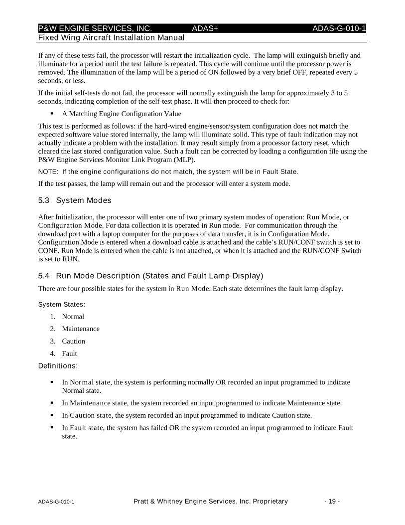
There are four possible states for the system in Run Mode. Each state determines the fault lamp display.
System States:
1. Normal
2. Maintenance
3. Caution
4. Fault
Definitions:
In Normal state, the system is performing normally OR recorded an input programmed to indicateNormal state.
In Maintenance state, the system recorded an input programmed to indicate Maintenance state.
In Caution state, the system recorded an input programmed to indicate Caution state.
In Fault state, the system has failed OR the system recorded an input programmed to indicate Faultstate.
P&W ENGINE SERVICES, INC. ADAS+ ADAS-G-010-1Fixed Wing Aircraft Installation Manual
ADAS-G-010-1 Pratt & Whitney Engine Services, Inc. Proprietary - 20 -
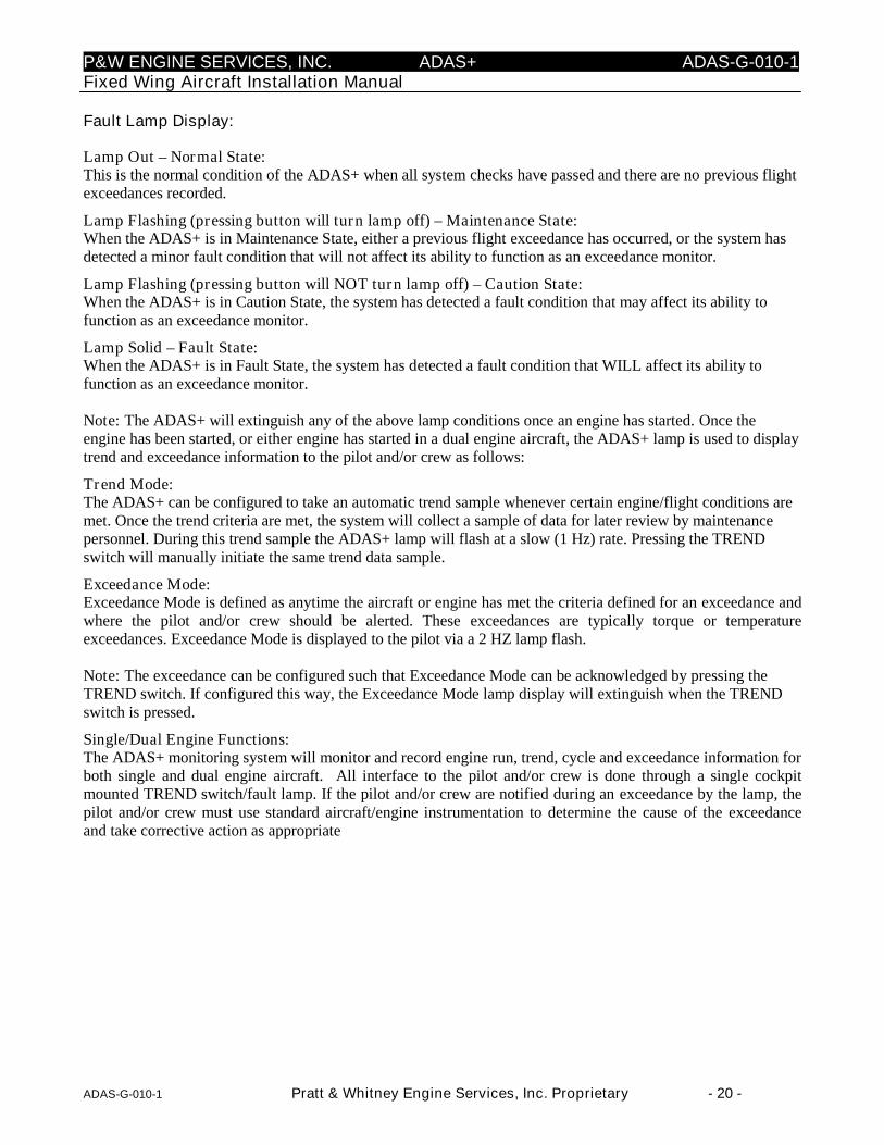
Fault Lamp Display:
Lamp Out – Normal State:This is the normal condition of the ADAS+ when all system checks have passed and there are no previous flightexceedances recorded.
Lamp Flashing (pressing button will turn lamp off) – Maintenance State:When the ADAS+ is in Maintenance State, either a previous flight exceedance has occurred, or the system hasdetected a minor fault condition that will not affect its ability to function as an exceedance monitor.
Lamp Flashing (pressing button will NOT turn lamp off) – Caution State:When the ADAS+ is in Caution State, the system has detected a fault condition that may affect its ability tofunction as an exceedance monitor.
Lamp Solid – Fault State:When the ADAS+ is in Fault State, the system has detected a fault condition that WILL affect its ability tofunction as an exceedance monitor.
Note: The ADAS+ will extinguish any of the above lamp conditions once an engine has started. Once theengine has been started, or either engine has started in a dual engine aircraft, the ADAS+ lamp is used to displaytrend and exceedance information to the pilot and/or crew as follows:
Trend Mode:The ADAS+ can be configured to take an automatic trend sample whenever certain engine/flight conditions aremet. Once the trend criteria are met, the system will collect a sample of data for later review by maintenancepersonnel. During this trend sample the ADAS+ lamp will flash at a slow (1 Hz) rate. Pressing the TRENDswitch will manually initiate the same trend data sample.
Exceedance Mode:Exceedance Mode is defined as anytime the aircraft or engine has met the criteria defined for an exceedance andwhere the pilot and/or crew should be alerted. These exceedances are typically torque or temperatureexceedances. Exceedance Mode is displayed to the pilot via a 2 HZ lamp flash.
Note: The exceedance can be configured such that Exceedance Mode can be acknowledged by pressing theTREND switch. If configured this way, the Exceedance Mode lamp display will extinguish when the TRENDswitch is pressed.
Single/Dual Engine Functions:The ADAS+ monitoring system will monitor and record engine run, trend, cycle and exceedance information forboth single and dual engine aircraft. All interface to the pilot and/or crew is done through a single cockpitmounted TREND switch/fault lamp. If the pilot and/or crew are notified during an exceedance by the lamp, thepilot and/or crew must use standard aircraft/engine instrumentation to determine the cause of the exceedanceand take corrective action as appropriate

P&W ENGINE SERVICES, INC. ADAS+ ADAS-G-010-1Fixed Wing Aircraft Installation Manual
ADAS-G-010-1 Pratt & Whitney Engine Services, Inc. Proprietary - 21 -
5.4.1 Fault Lamp Display for Optional ENGINE/TREND Split Lamp
Trend Lamp Out - Normal State:This is the normal condition of the ADAS+ when all system checks have passed and there are no previous flightexceedances recorded.
Trend Lamp Flashing (pressing button will turn lamp off) - Maintenance State:When the ADAS+ is in Maintenance State, either a previous flight exceedance has occurred, or the system hasdetected a minor fault condition that will not affect its ability to function as an exceedance monitor.
Trend Lamp Flashing (pressing button will NOT turn lamp off) - Caution State:When the ADAS+ is in Caution State, t either a previous flight exceedance has occurred, or the system hasdetected a fault condition that may affect its ability to function as an exceedance monitor.
Trend Lamp Solid - Fault State:When the ADAS+ is in Fault State, either a previous flight exceedance has occurred, or the system has detecteda fault condition that WILL affect its ability to function as an exceedance monitor.
Engine Lamp Solid:When the ENGINE lamp is illuminated, a previous engine flight exceedance has occurred.
Note: The ADAS+ will extinguish any of the above lamp conditions once an engine has started. Once theengine has been started, or either engine has started in a dual engine aircraft, the ADAS+ lamp is used to displaytrend and exceedance information to the pilot and/or crew as follows:
Trend Mode:The ADAS+ can be configured to take an automatic trend sample whenever certain engine/flight conditions aremet. Once the trend criteria are met, the system will collect a sample of data for later review by maintenancepersonnel. During this trend sample the ADAS+ Trend lamp will flash at a slow (1 Hz) rate. Pressing theEngine/Trend Split Lamp switch will manually initiate the same trend data sample.
Exceedance Mode:Exceedance Mode is defined as anytime the aircraft or engine has met the criteria defined for an exceedance andwhere the pilot and/or crew should be alerted. Engine exceedances are displayed to the pilot via a solid amberENGINE lamp. Aircraft exceedances are displayed to the pilot via a solid white Trend lamp.
Note: The Exceedance Mode will be configured so that the exceedance can be acknowledged by pressing theENGINE/TREND switch. When configured this way, the Exceedance Mode lamp display will extinguish whenthe ENGINE/TREND switch is pressed.
Single/Dual Engine Functions:The ADAS+ monitoring system will monitor and record engine run, trend, cycle and exceedance information forboth single and dual engine aircraft. All interface to the pilot and/or crew is done through a single cockpitmounted ENGINE/TREND Split Lamp. If the pilot and/or crew are notified during an exceedance by the lamp,the pilot and/or crew must use standard aircraft/engine instrumentation to determine the cause of the exceedanceand take corrective action as appropriate.
P&W ENGINE SERVICES, INC. ADAS+ ADAS-G-010-1Fixed Wing Aircraft Installation Manual
ADAS-G-010-1 Pratt & Whitney Engine Services, Inc. Proprietary - 22 -
6 SYSTEM CONFIGURATION AND CALIBRATION
The ADAS+ is a combination of hardware and software designed to have a wide range of application. In orderto correctly operate with the specific aircraft type it is installed in, the system must first be configured to expectthe particular sensor and signal combinations available on that aircraft as well as the engine type and othernecessary information.
When it has been properly configured, the ADAS+ must be calibrated to correctly compensate for the preciserange and level of the available sensor signals on that specific aircraft. This last function is similar to thecalibration performed on aircraft instruments, and may, in part, use some of the same calibration equipment.The system is also capable of being calibrated without such equipment, by utilizing the existing cockpit flightinstruments as calibration standards. However, this option depends on the accuracy of the cockpit instruments(and their own calibration), and is more difficult to perform. It requires flying the aircraft to get a useful range ofreadings. The preferred method of calibration for ADAS+ is to use conventional calibration equipment.
The installer, with the help of a computer and software communication tools, performs configuration andcalibration. Configuration and calibration require a laptop computer connected to the system with a downloadcable and running P&W Engine Services Monitor Link Program (MLP). The MLP gives field personnel theability to monitor the sensors in real time (Live Data Display) as well as to alter the configuration andcalibration data stored by the system.
In addition to MLP, P&W Engine Services offers an Internet based data management and analysis system calledTurbineTracker™. MLP and TurbineTracker™ make it possible to quickly transfer and manage the aircraft’sconfiguration and calibration data, as well as operational data (log data) for fleet comparison and analysis. TheTurbineTracker™ website is located at www.turbinetracker.aero. To obtain a TurbineTracker™ useraccount and password, contact P&W Engine Services Help Desk.
Current manuals for both TurbineTracker and MLP are available through the TurbineTracker™ website. Thefollowing sections and instructions for configuration and calibration of the system require familiarity with theMLP and TurbineTracker™ manuals and software. While this section of the installation manual cannot replacethe software manuals, a few of the special terms and concepts used in the configuration and calibrationinstructions are briefly described in this manual. See the software manuals for full descriptions and proceduresfor use of the applicable software product.
6.1 Definitions
Configuration File: An MLP data file that contains engine, sensor, and calibration information for a specificaircraft. This information is transmitted to the processor during configuration and updated during calibration.
Configuration Version: A number stored with a particular configuration file. The MLP and TurbineTracker™both maintain version numbers of the current configuration file in use. These must match each other andcorrespond with the data collected and stored by the system processor. When a new calibration is performed andaccepted, the version number is automatically incremented.
Live Data Display: An MLP mode of operation that presents periodically updated aircraft sensor readings inreal time. Live Data Display may be used in flight and on the ground when adjusting the calibration or testingand troubleshooting the system.
Log Data: The stored operational aircraft exceedance, event, cycle, and sensor readings collected by theprocessor. In normal aircraft use, the information gathering function of the system creates Log Data. This datais stored in raw form (a Log File) and can be extracted and further processed into useful information throughMLP and TurbineTracker™.
MLP (Monitor Link Program): The P&W Engine Services communication program is used to transfer data toand from the processor. It can also display live operational data.
MLU (Monitor Link Unit): Files loaded into MLP that enables MLP to communicate with the ADAS+.
P&W ENGINE SERVICES, INC. ADAS+ ADAS-G-010-1Fixed Wing Aircraft Installation Manual
ADAS-G-010-1 Pratt & Whitney Engine Services, Inc. Proprietary - 23 -
One Point Offset Calibration (P2): A method that uses a single reading (or point) to correct (calibrate) asensor signal. A One Point Offset Calibration is a less precise offset method of calibration than a Two PointCalibration. A One Point Offset Calibration is used when the calibration occurs on the low end of a sensor’spotential operating range and a Two Point Calibration cannot be accomplished. To increase the useful precisionof the one point offset method, a reading at the low end of a sensor’s signal range is preferred. For example, if asensor reading is supposed to fall between 10 degrees and 100 degrees, a test reading at 20 degrees will calibratethe system better than one at 70 degrees. If a reading at 0 has been attempted as a One Point Offset Calibration,the system has not been usefully calibrated at all.
NOTE: The One Point Offset Calibration Method only ensures that the low end of a sensor signal’s rangeis calibrated. Never use 0 when accomplishing the One Point Offset Calibration Method.
One Point Slope Calibration (P1): A second method that uses a single reading (or point) to correct (calibrate)a sensor signal. A One Point Slope Calibration is a less precise method of calibration than a Two PointCalibration. A One Point Slope Calibration is used when the calibration occurs on the high end of a sensor’spotential operating range and a Two Point calibration cannot be accomplished. To increase the useful precisionof the one point slope method, a reading at the high end of a sensor’s signal range is preferred. For example, if asensor reading is supposed to fall between 100 and 500, a test reading at 400 will calibrate the system better thanone at 150. If a reading at 0 has been attempted as a One Point Slope Calibration, the system has not beenusefully calibrated at all.
NOTE: The One Point Slope Calibration Method only ensures that the high end of a sensor signal’srange is calibrated. Never use 0 when accomplishing the One Point Slope Calibration Method.
Two Point Calibration (P1 & P2): The most accurate method of calibration, requiring both a low and highvalue to correct (calibrate) a sensor signal. A Two Point Calibration occurs when calibration equipment or themanual sensor calibration methods are used. If a reading at 0 has been attempted as a Two Point Calibration,the system has not been usefully calibrated at all.
NOTE: The Two Point Calibration Method ensures that the low end AND high end of a sensor’s signalrange are calibrated. Never use 0 when accomplishing the Two Point Calibration Method.
P&W ENGINE SERVICES, INC. ADAS+ ADAS-G-010-1Fixed Wing Aircraft Installation Manual
ADAS-G-010-1 Pratt & Whitney Engine Services, Inc. Proprietary - 24 -
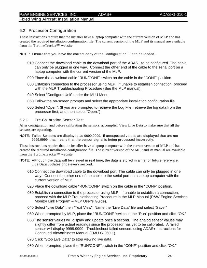
6.2 Processor Configuration
These instructions require that the installer have a laptop computer with the current version of MLP and hascreated the required installation configuration file. The current version of the MLP and its manual are availablefrom the TurbineTracker™ website.
NOTE: Ensure that you have the correct copy of the Configuration File to be loaded.
010 Connect the download cable to the download port of the ADAS+ to be configured. The cablecan only be plugged in one way. Connect the other end of the cable to the serial port on alaptop computer with the current version of the MLP.
020 Place the download cable “RUN/CONF” switch on the cable in the “CONF” position.
030 Establish connection to the processor using MLP. If unable to establish connection, proceedwith the MLP Troubleshooting Procedure (See the MLP manual).
040 Select “Configure Unit” under the MLU Menu.
050 Follow the on-screen prompts and select the appropriate installation configuration file.
060 Select “Open”. (If you are prompted to retrieve the Log File, retrieve the log data from theprocessor first, and then select “Open.”)
6.2.1 Pre-Calibration Sensor Test
After configuration and before calibrating the sensors, accomplish View Live Data to make sure that all thesensors are operating.
NOTE: Failed Sensors are displayed as 9999.9999. If unexpected values are displayed that are not9999.9999, that means that the sensor signal is being processed incorrectly.
These instructions require that the installer have a laptop computer with the current version of MLP and hascreated the required installation configuration file. The current version of the MLP and its manual are availablefrom the TurbineTracker™ website.
NOTE: Although the data will be viewed in real time, the data is stored in a file for future reference.Live Data updates once every second.
010 Connect the download cable to the download port. The cable can only be plugged in oneway. Connect the other end of the cable to the serial port on a laptop computer with thecurrent version of MLP.
020 Place the download cable “RUN/CONF” switch on the cable in the “CONF” position.
030 Establish a connection to the processor using MLP. If unable to establish a connection,proceed with the MLP Troubleshooting Procedure in the MLP Manual (P&W Engine ServicesMonitor Link Program – MLP User’s Guide).
040 Select “Live Data” then “Text View”. Name the “Live Data” file and select “Save.”
050 When prompted by MLP, place the “RUN/CONF “switch in the “Run” position and click “OK.”
060 The sensor values will display and update once a second. The analog sensor values mayslightly differ from actual readings since the processor has yet to be calibrated. A failedsensor will display 9999.9999. Troubleshoot failed sensors using ADAS+ Instructions forContinued Airworthiness Manual (EMU-G-260-1).
070 Click “Stop Live Data” to stop viewing live data.
080 When prompted, place the “RUN/CONF” switch in the “CONF” position and click “OK.”

P&W ENGINE SERVICES, INC. ADAS+ ADAS-G-010-1Fixed Wing Aircraft Installation Manual
ADAS-G-010-1 Pratt & Whitney Engine Services, Inc. Proprietary - 25 -
6.3 Calibration of Optional Sensors
The ADAS+ is capable of measuring additional engine and airframe parameters. The only sensor that needs tobe calibrated at this time is the vertical accelerometer (no longer available as of March 1, 2009). This must bedone by physically removing the unit from its mounting and performing the following steps:
010 Connect the download cable to the download port. The cable can only be plugged in oneway. Connect the other end of the cable to the serial port on a laptop computer with thecurrent version of the MLP.
020 Place the download cable “RUN/CONF” switch on the cable in the “CONF” position.
030 Establish a connection to the processor using the MLP. If unable to establish a connection,proceed with the MLP Troubleshooting Procedure in the MLP Manual (P&W Engine ServicesMonitor Link Program – MLP User’s Guide).
040 Select “Sensor Calibration” under the MLU Menu.
050 Select “Vertical Accl” And perform a Two Point Calibration by using the following values:
NOTE: The Vertical Accelerometer is no longer available as of March 1, 2009.
a. Turn the accelerometer crossbow label side down and enter -1 in the Upper Box
b. Turn the accelerometer crossbow label side up and enter 1 in the Lower Box
060 After calibration, upload the new configuration file version to your TurbineTracker™ account.It is important to keep the processor, MLP, and Turbine Tracker™ configuration versionssynchronized.
P&W ENGINE SERVICES, INC. ADAS+ ADAS-G-010-1Fixed Wing Aircraft Installation Manual
ADAS-G-010-1 Pratt & Whitney Engine Services, Inc. Proprietary - 26 -
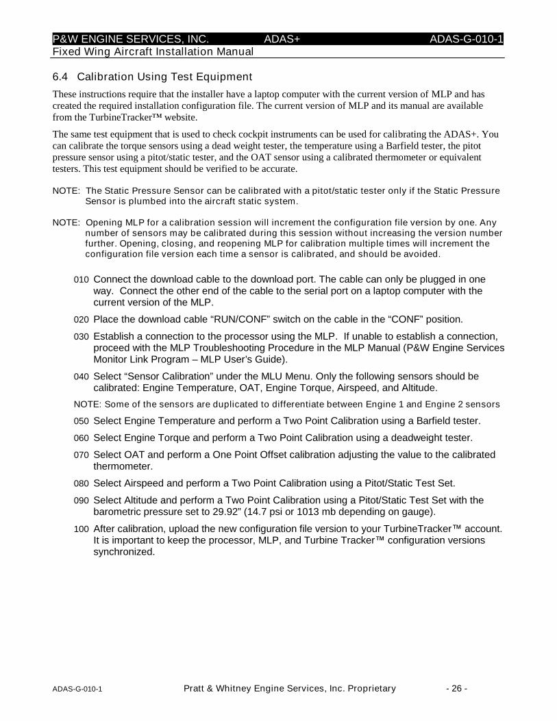
6.4 Calibration Using Test Equipment
These instructions require that the installer have a laptop computer with the current version of MLP and hascreated the required installation configuration file. The current version of MLP and its manual are availablefrom the TurbineTracker™ website.
The same test equipment that is used to check cockpit instruments can be used for calibrating the ADAS+. Youcan calibrate the torque sensors using a dead weight tester, the temperature using a Barfield tester, the pitotpressure sensor using a pitot/static tester, and the OAT sensor using a calibrated thermometer or equivalenttesters. This test equipment should be verified to be accurate.
NOTE: The Static Pressure Sensor can be calibrated with a pitot/static tester only if the Static PressureSensor is plumbed into the aircraft static system.
NOTE: Opening MLP for a calibration session will increment the configuration file version by one. Anynumber of sensors may be calibrated during this session without increasing the version numberfurther. Opening, closing, and reopening MLP for calibration multiple times will increment theconfiguration file version each time a sensor is calibrated, and should be avoided.
010 Connect the download cable to the download port. The cable can only be plugged in oneway. Connect the other end of the cable to the serial port on a laptop computer with thecurrent version of the MLP.
020 Place the download cable “RUN/CONF” switch on the cable in the “CONF” position.
030 Establish a connection to the processor using the MLP. If unable to establish a connection,proceed with the MLP Troubleshooting Procedure in the MLP Manual (P&W Engine ServicesMonitor Link Program – MLP User’s Guide).
040 Select “Sensor Calibration” under the MLU Menu. Only the following sensors should becalibrated: Engine Temperature, OAT, Engine Torque, Airspeed, and Altitude.
NOTE: Some of the sensors are duplicated to differentiate between Engine 1 and Engine 2 sensors
050 Select Engine Temperature and perform a Two Point Calibration using a Barfield tester.
060 Select Engine Torque and perform a Two Point Calibration using a deadweight tester.
070 Select OAT and perform a One Point Offset calibration adjusting the value to the calibratedthermometer.
080 Select Airspeed and perform a Two Point Calibration using a Pitot/Static Test Set.
090 Select Altitude and perform a Two Point Calibration using a Pitot/Static Test Set with thebarometric pressure set to 29.92” (14.7 psi or 1013 mb depending on gauge).
100 After calibration, upload the new configuration file version to your TurbineTracker™ account.It is important to keep the processor, MLP, and Turbine Tracker™ configuration versionssynchronized.
P&W ENGINE SERVICES, INC. ADAS+ ADAS-G-010-1Fixed Wing Aircraft Installation Manual
ADAS-G-010-1 Pratt & Whitney Engine Services, Inc. Proprietary - 27 -
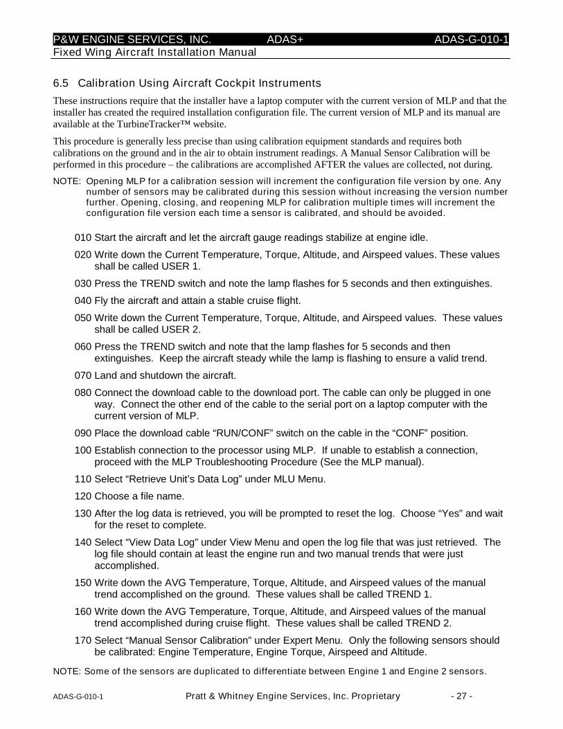
6.5 Calibration Using Aircraft Cockpit Instruments
These instructions require that the installer have a laptop computer with the current version of MLP and that theinstaller has created the required installation configuration file. The current version of MLP and its manual areavailable at the TurbineTracker™ website.
This procedure is generally less precise than using calibration equipment standards and requires bothcalibrations on the ground and in the air to obtain instrument readings. A Manual Sensor Calibration will beperformed in this procedure – the calibrations are accomplished AFTER the values are collected, not during.
NOTE: Opening MLP for a calibration session will increment the configuration file version by one. Anynumber of sensors may be calibrated during this session without increasing the version numberfurther. Opening, closing, and reopening MLP for calibration multiple times will increment theconfiguration file version each time a sensor is calibrated, and should be avoided.
010 Start the aircraft and let the aircraft gauge readings stabilize at engine idle.
020 Write down the Current Temperature, Torque, Altitude, and Airspeed values. These valuesshall be called USER 1.
030 Press the TREND switch and note the lamp flashes for 5 seconds and then extinguishes.
040 Fly the aircraft and attain a stable cruise flight.
050 Write down the Current Temperature, Torque, Altitude, and Airspeed values. These valuesshall be called USER 2.
060 Press the TREND switch and note that the lamp flashes for 5 seconds and thenextinguishes. Keep the aircraft steady while the lamp is flashing to ensure a valid trend.
070 Land and shutdown the aircraft.
080 Connect the download cable to the download port. The cable can only be plugged in oneway. Connect the other end of the cable to the serial port on a laptop computer with thecurrent version of MLP.
090 Place the download cable “RUN/CONF” switch on the cable in the “CONF” position.
100 Establish connection to the processor using MLP. If unable to establish a connection,proceed with the MLP Troubleshooting Procedure (See the MLP manual).
110 Select “Retrieve Unit’s Data Log” under MLU Menu.
120 Choose a file name.
130 After the log data is retrieved, you will be prompted to reset the log. Choose “Yes” and waitfor the reset to complete.
140 Select “View Data Log” under View Menu and open the log file that was just retrieved. Thelog file should contain at least the engine run and two manual trends that were justaccomplished.
150 Write down the AVG Temperature, Torque, Altitude, and Airspeed values of the manualtrend accomplished on the ground. These values shall be called TREND 1.
160 Write down the AVG Temperature, Torque, Altitude, and Airspeed values of the manualtrend accomplished during cruise flight. These values shall be called TREND 2.
170 Select “Manual Sensor Calibration” under Expert Menu. Only the following sensors shouldbe calibrated: Engine Temperature, Engine Torque, Airspeed and Altitude.
NOTE: Some of the sensors are duplicated to differentiate between Engine 1 and Engine 2 sensors.

P&W ENGINE SERVICES, INC. ADAS+ ADAS-G-010-1Fixed Wing Aircraft Installation Manual
ADAS-G-010-1 Pratt & Whitney Engine Services, Inc. Proprietary - 28 -
180 Accomplish a Two Point Calibration for Temperature, Torque, Altitude, and Airspeed.
NOTE: You will see four empty boxes for each calibration
Enter the sensor values collected in TREND 1 in the upper left hand box (Unit’s ValueColumn, Top Row)
Enter the sensor values collected in TREND 2 in the lower left hand box (Unit’s Value,Bottom Row)
Enter the gauge values collected in USER 1 in the upper right hand box (Calibrate toValues Column, Top Row)
Enter the gauge values collected in USER 2 in the lower right hand box (Calibrate toValues Column, Bottom Row)
190 After completing the calibrations, exit Manual Sensor Calibration mode.
200 Select “Sensor Calibration” under the MLU Menu. Only the OAT sensor should be calibrated.
210 Select OAT and perform a One Point Offset Calibration and adjust the value to the reading onthe calibrated thermometer.
220 After calibration, upload the new Configuration File version to your TurbineTracker account. It isimportant to keep the processor, MLP and Turbine Tracker™ configuration versionssynchronized
Recommended calibration points
when using TEST EQUIPMENT
Calibrated Two Point Calibration Single Point Offset
Sensor Point 1 Point 2 Units Calibration Equipment
Airspeed 30 VNE N/A knots Pitot-Static Test Kit
Altitude (helicopters) 3,000 12,000Pressure Altitude at 29.92" Hg(14.7 psi or 1013 mb) feet Pitot-Static Test Kit
Altitude (fixed wing) 5,000 20,000Pressure Altitude at 29.92" Hg(14.7 psi or 1013 mb) feet Pitot-Static Test Kit
ITT 400 1,000 N/A °C Barfield Meter
OAT N/A N/A Ambient °C Calibrated Digital Thermometer
Torque 30 Max takeoff N/A % Dead-Weight Tester
500 Max takeoff N/A foot-lbs Dead-Weight Tester
approx 20 Max takeoff N/A psi Dead-Weight Tester
Mast Torque 0 Max N/A % Aircraft Instrument (Pilot OVER TORQ warning light)
(if applicable) 0 Max N/A foot-lbs Aircraft Instrument (Pilot OVER TORQ warning light)
(if applicable) 0 Max N/A psi Aircraft Instrument (Pilot OVER TORQ warning light)
***NOTE: When performing a Manual Calibration, use NORMAL OPERATING RANGES for engine and Airframe***

P&W ENGINE SERVICES, INC. ADAS+ ADAS-G-010-1Fixed Wing Aircraft Installation Manual
ADAS-G-010-1 Pratt & Whitney Engine Services, Inc. Proprietary - 29 -
7 AIRCRAFT TESTING
While following the requirements of FAR 91.407, it is recommended that the aircraft be inspected forairworthiness prior to testing. If the ground and/or flight testing of the modified aircraft are not successfullycompleted, the aircraft should be returned to the original aircraft configuration until the tests are completed andacceptable.
After installation and calibration of the ADAS+, it is recommended that ground and flight tests be performed toverify the correct operation of the system in the aircraft. The following sections outline the suggested aircraftand system test procedures.
7.1 Aircraft Ground Test
The circuit breaker for the ADAS+ may not be accessible with the engine running. This is true for the CessnaCaravan. Please refer to the appropriate Ground Test for the particular aircraft under test.
For All Listed Engine Models with Inaccessible Circuit Breaker:
010 With the aircraft battery connected and master switch on, verify that the fault lamp illuminates,indicating system boot-up. After approximately 5 seconds, the lamp will extinguish and either:
a. Remain extinguished (NORMAL STATE)
b. Flash (MAINTENANCE OR CAUTION STATE)
c. Illuminate Solid (FAULT STATE)
If the processor does NOT go into NORMAL STATE, retrieve the log data, and troubleshoot thesystem.
020 Turn battery switch off
030 With external power connected to aircraft, apply external power to the aircraft bus
040 Power on all avionics
050 Tune Comm 1 and Comm 2 VHF radios to the frequencies in Table 4 and verify that there is nointerference caused by the ADAS+. This can normally be conducted by checking for auto squelchbreak on each listed frequency.
060 If interference is suspected at any particular frequency, pull the ADAS+ circuit breaker to see if theinterference subsides
070 If the aircraft is equipped with a GPS navigation receiver, display the satellite status page and cyclepower on the ADAS+.
080 Verify that the GPS signal strength is not affected by the operation of the ADAS+
090 Tune the #1 and #2 VHF NAV receivers to receive a valid navigational signal from either a VOR ramptester or a locally tuned VOR navigation transmitter
100 Verify that valid course deviation and a retracted NAV flag are displayed on the HIS or the VORcourse indicator.
110 Cycle power on the ADAS+ and verify that there is no effect on the displayed NAV data
120 If the aircraft is equipped with an autopilot, initiate autopilot self test. This may require pulling, andthen resetting the autopilot circuit breaker with power applied to the ADAS+

P&W ENGINE SERVICES, INC. ADAS+ ADAS-G-010-1Fixed Wing Aircraft Installation Manual
ADAS-G-010-1 Pratt & Whitney Engine Services, Inc. Proprietary - 30 -
130 Verify that the autopilot completes a successful self-test.
140 Survey the aircraft for any other installed equipment that may be affected by interference from theADAS+. Perform any additional tests as required to determine if the ADAS+ creates objectionableinterference. This may be accomplished by pulling the ADAS+ circuit breaker while observing thesubject equipment. List the additional equipment tested and any observed effects in theElectromagnetic Compatibility Testing Table (See Table 5).
150 Remove external power from aircraft and start engine
160 Monitor the engine torque lines for oil leaks. If leaks are found, shut down and correct the leaks.
Frequency Pass/Fail Frequency Pass/Fail
118.00 MHZ 127.00 MHZ
119.00 MHZ 128.00 MHZ
120.00 MHZ 129.00 MHZ
121.00 MHZ 130.00 MHZ
122.00 MHZ 131.00 MHZ
123.00 MHZ 132.00 MHZ
124.00 MHZ 133.00 MHZ
125.00 MHZ 134.00 MHZ
126.00 MHZ 135.00 MHZ
Table 4: VHF Frequency Table
For All Listed Engine Models with Accessible Circuit Breaker:
Engine Running:
010 Start engine.
020 Monitor the engine torque lines for oil leaks. If leaks are found, shut down and correct the leaks
030 With the engine running and the ADAS+ system operational, tune Comm 1 and Comm 2 VHF radiosto the frequencies in Table 4 and verify that there is no interference caused by the ADAS+. This cannormally be conducted by checking for auto squelch break on each listed frequency
040 If interference is suspected at any particular frequency, pull the ADAS+ circuit breaker to see if theinterference subsides.
050 If the aircraft is equipped with a GPS navigation receiver, display the satellite status page and cyclepower on the ADAS+.
060 Verify that the GPS signal strength is not affected by the operation of the ADAS+
070 Tune the #1 and #2 VHF NAV receivers to receive a valid navigational signal from either a VOR ramptester or a locally tuned VOR navigation transmitter
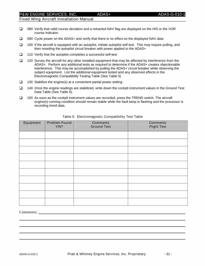
P&W ENGINE SERVICES, INC. ADAS+ ADAS-G-010-1Fixed Wing Aircraft Installation Manual
ADAS-G-010-1 Pratt & Whitney Engine Services, Inc. Proprietary - 31 -
080 Verify that valid course deviation and a retracted NAV flag are displayed on the HIS or the VORcourse indicator.
090 Cycle power on the ADAS+ and verify that there is no effect on the displayed NAV data
100 If the aircraft is equipped with an autopilot, initiate autopilot self test. This may require pulling, andthen resetting the autopilot circuit breaker with power applied to the ADAS+
110 Verify that the autopilot completes a successful self-test
120 Survey the aircraft for any other installed equipment that may be affected by interference from theADAS+. Perform any additional tests as required to determine if the ADAS+ creates objectionableinterference. This may be accomplished by pulling the ADAS+ circuit breaker while observing thesubject equipment. List the additional equipment tested and any observed effects in theElectromagnetic Compatibility Testing Table (See Table 5)
130 Stabilize the engine(s) at a convenient partial power setting
140 Once the engine readings are stabilized, write down the cockpit instrument values in the Ground TestData Table (See Table 6).
150 As soon as the cockpit instrument values are recorded, press the TREND switch. The aircraftengine(s) running condition should remain stable while the fault lamp is flashing and the processor isrecording trend data.
Table 5: Electromagnetic Compatibility Test Table
Equipment Problem FoundY/N?
CommentsGround Test
CommentsFlight Test
Comments:
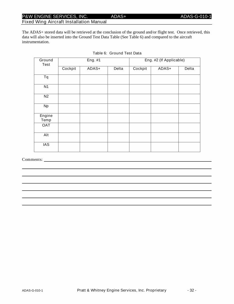
P&W ENGINE SERVICES, INC. ADAS+ ADAS-G-010-1Fixed Wing Aircraft Installation Manual
ADAS-G-010-1 Pratt & Whitney Engine Services, Inc. Proprietary - 32 -
The ADAS+ stored data will be retrieved at the conclusion of the ground and/or flight test. Once retrieved, thisdata will also be inserted into the Ground Test Data Table (See Table 6) and compared to the aircraftinstrumentation.
Table 6: Ground Test Data
Eng. #1 Eng. #2 (If Applicable)GroundTest
Cockpit ADAS+ Delta Cockpit ADAS+ Delta
Tq
N1
N2
Np
EngineTemp
OAT
Alt
IAS
Comments:

P&W ENGINE SERVICES, INC. ADAS+ ADAS-G-010-1Fixed Wing Aircraft Installation Manual
ADAS-G-010-1 Pratt & Whitney Engine Services, Inc. Proprietary - 33 -
7.2 Aircraft Flight Test
010 Takeoff and climb to cruise altitude.
020 During the en-route phase of the flight, check all radios and navigation equipment for normalperformance. Ensure the absence of electromagnetic interference between the ADAS+ and the restof the aircraft systems. Record the results of all tests in the Electromagnetic Compatibility Test Table(See Table 5).
030 Check all other aircraft equipment and verify normal operation.
040 Once the engine readings are stabilized, record the cockpit instrument values in the Flight Test DataTable (See Table 7).
050 As soon as the data is recorded, press the TREND switch. Ensure the aircraft is stable while thefault lamp is flashing and the processor is recording data.
The ADAS+ stored data will be retrieved at the conclusion of the ground and/or flight test. Once retrieved, thisdata will also be inserted into the Flight Test Data Table (See Table 7) and compared to the aircraftinstrumentation.
Table 7: Flight Test Data
Eng. #1 Eng. #2 (If Applicable)GroundTest
Cockpit ADAS+ Delta Cockpit ADAS+ Delta
Tq
N1
N2
Np
EngineTemp
OAT
Alt
IAS
Comments:
P&W ENGINE SERVICES, INC. ADAS+ ADAS-G-010-1Fixed Wing Aircraft Installation Manual
ADAS-G-010-1 Pratt & Whitney Engine Services, Inc. Proprietary - 34 -
7.3 Test Data Retrieval and Review
After the ground and/or flight tests have been completed perform the following:
010 Download the ADAS+ trend data for each engine to a laptop computer with MLP.
020 Fill in the Ground and/or Flight Test Table (Table 6 and Table 7) with the trend data.
030 Review the tables for any discrepancies between the ADAS+ data and the aircraft instrumentreadings.
7.4 Continued Airworthiness Instructions
See ADAS+ Instructions for Continued Airworthiness (ADAS-G-260-1) for troubleshooting the system. If yourequire further assistance, contact the Help Desk:
Pratt & Whitney Engine Services, Inc.Help Desk249 Vanderbilt AvenueNorwood, MA 02062(781) 762-8600Fax: (781) 762-2287E-mail: [email protected]

P&W ENGINE SERVICES, INC. ADAS+ ADAS-G-010-1Fixed Wing Aircraft Installation Manual
ADAS-G-010-1 Pratt & Whitney Engine Services, Inc. Proprietary - 35 -
8 SERVICE
8.1 Customer Support
P&W Engine Services provides customer support in accordance with the product warranty detailed within thecustomer’s sales contract. If you have any questions concerning any P&W Engine Services product, please donot hesitate to contact us. Our Help Desk accepts calls Monday through Friday between 9:00 AM and 5:00 PMEST. Please have your model and serial number ready when you call.
Pratt & Whitney Engine Services, Inc.Help Desk249 Vanderbilt AvenueNorwood, MA 02062(781) 762-8600Fax: (781) 762-2287E-mail: [email protected]
P&W ENGINE SERVICES, INC. ADAS+ ADAS-G-010-1Fixed Wing Aircraft Installation Manual
ADAS-G-010-1 Pratt & Whitney Engine Services, Inc. Proprietary - 36 -
9 SPECIFICATIONS
9.1 System Specifications
GENERAL
Chassis Size (each): 3.7" x 1.7" x 6.9"
Chassis Weight: 1.4 lbs (22 oz.)
System Weight: Approximately 11 lbs. – Refer to applicable addendum for actual system weight
POWER REQUIREMENTS
Voltage Range: 11 to 32 VDC
Current Draw < 1.0 A
Power Draw 8 Watts operating
20 mWatts standby
ENVIRONMENTAL (ALL TESTS TO RTCA/DO-160D)
Test Performed RTCA Section Level
Temperature & Altitude Section 4.0 Equipment tested to category D3
- Low Temperature Section 4.5.1 - 40 ºC Operating
- High Temperature Section 4.5.2 70 ºC, +85 ºC Short-Time
Operating
- In-Flight Loss of Cooling Section 4.5.4 Test not required
- Altitude Test Section 4.6.1 50,000 Ft
- Decompression Test Section 4.6.2 Test not required
- Overpressure Test Section 4.6.3 Test not required
Temperature Variation Section 5.0 Equipment tested to category B
Humidity Section 6.0 Equipment tested to category B
Shock Section 7.0 Equipment tested to category B
- Operational Section 7.2 Equipment tested to category B
- Crash Safety Test Section 7.3 Equipment tested to category B
Vibration Section 8.0 Robust test performed to category R2
Explosion Section 9.0 Equipment identified as category E
Waterproofness Section 10.0 Equipment identified as category R

P&W ENGINE SERVICES, INC. ADAS+ ADAS-G-010-1Fixed Wing Aircraft Installation Manual
ADAS-G-010-1 Pratt & Whitney Engine Services, Inc. Proprietary - 37 -
Fluids Susceptibility Section 11.0 Equipment identified as category F
Sand and Dust Section 12.0 Equipment identified as category D
Fungus Section 13.0 Equipment identified as category F
Salt Spray Section 14.0 Equipment identified as category S
Magnetic Effect Section 15.0 Equipment identified as category Z
Power Input Section 16.0 Equipment tested to category B
Voltage Spikes Section 17.0 Equipment tested to category B
Audio Freq. Susceptibility Section 18.0 Equipment tested to category B
Induced Signal Susceptibility Section 19.0 Equipment tested to category B
Radio Freq. Susceptibility Section 20.0 Equipment identified as category V
Radio Freq. Emission Section 21.0 Equipment tested to category L
Transient Susceptibility Section 22.0 Equipment identified as category XXC2
Lightning Direct Effect Section 23.0 Equipment identified as category X
Icing Section 24.0 Test Not Required
Electrostatic Discharge Section 25.0 Equipment identified as category A
DATA INTERFACE
Computer Interface: RS-485 Serial Interface, 57,600 Baud
SYSTEM SOFTWARE
The ADAS+ has been designed and tested to RTCA/DO-178B Level C
SAMPLE RATE
The ADAS+ samples Engine Temperature up to 50 times per second. All other inputs are sampled up to 5times per second
DATA STORAGE
System Data: Installation ID / Version
Engine Run Data: Engine Run Date, Engine Run Time, Engine Run Duration, MaximumSensor Values Observed, Cycles Counted, Maximum Start Temp, MinimumBattery Voltage, Start Duration
Exceedance Data: Exceedance Date, Exceedance Time, Exceedance Duration, ExceedanceType, Maximum/Minimum Value Observed, Average Value Observed, TimeHistory Sensor Recording
Trend Sample: Trend Type (Auto/Manual), Trend Time, Sensor Max Value Observed,Sensor Average Value Observed
Flash Storage Memory: 4 MB

P&W ENGINE SERVICES, INC. ADAS+ ADAS-G-010-1Fixed Wing Aircraft Installation Manual
ADAS-G-010-1 Pratt & Whitney Engine Services, Inc. Proprietary - 38 -
9.2 SPECIFICATIONS FOR P&W ENGINE SERVICES SUPPLIED SENSORS
ENGINE - TORQUE PRESSURE SENSOR
The ADAS+ provides a torque pressure signal interface as follows:
Parameter Specification Comments
Operating Pressure 0-150 PSIG
Proof Pressure 450 PSIG
Hysteresis & Repeatability +/- .05% of Span MAX
Environmental -40 ºC to 125 ºC Operating
AIRCRAFT - PA AMBIENT PRESSURE SENSOR
The ADAS+ provides a Pa sensor and interface as follows:
Parameter Specification Comments
Operating Pressure 0-15 PSIA
Proof Pressure 75 PSI
Hysteresis & Repeatability +/- .05% of Span MAX
Environmental -40 ºC to 125 ºC Operating
AIRCRAFT - PITOT PRESSURE SENSOR
The ADAS+ provides a pitot pressure sensor and interface as follows:
Parameter Specification Comments
Operating Pressure 0-3 PSIA
Proof Pressure 6 PSI
Hysteresis & Repeatability +/- .05% of Span MAX
Environmental -40 ºC to 125 ºC Operating
AIRCRAFT - TA AMBIENT TEMPERATURE SENSOR
The ADAS+ provides a Ta sensor and interface as follows:
Parameter Specification Comments
Sensor Type Platinum Resistance Probe
Accuracy +/- 3 ºC (Uncalibrated)
+/- 1 ºC (Calibrated)
Range -54 ºC To 100 ºC

P&W ENGINE SERVICES, INC. ADAS+ ADAS-G-010-1Fixed Wing Aircraft Installation Manual
ADAS-G-010-1 Pratt & Whitney Engine Services, Inc. Proprietary - 39 -
AIRCRAFT – ACCELEROMETER
NOTE: The Vertical Accelerometer is no longer available as of March 1, 2009.
The ADAS+ provides a vertical accelerometer and interface as follows:
Parameter Specification Comments
Accuracy +/- .06G
Range +/- 5G
9.3 Interface Requirements For Aircraft Sensors
FAULT/CAUTION LAMP
The ADAS+ may interface with an existing cockpit lamp.
The lamp shall have the following characteristics:
Nominal Voltage +28 VDC
Current 40 mA +/- 10%
Power Dissipation 1.24 Watts
Average Rated Life (0°C) 1,500 Hours
PILOT COMMAND SWITCH
The ADAS+ may interface with an existing cockpit switch. The input shall have the following characteristics:
Parameter Specification Comments
Input Threshold 0 VDC
> 0 VDC
Switch Depressed
Switch Disengaged
POWER INPUT +28VDC
The ADAS+ requires power via one (1) 1 Amp circuit breaker and one (1) 1 Amp fuse, both installed in a remotelocation. The input shall have the following characteristics:
Parameter Specification Comments
Nominal +28 VDC
Typical 20 – 30 VDC
Minimum 11 VDC
Maximum 32 VDC

P&W ENGINE SERVICES, INC. ADAS+ ADAS-G-010-1Fixed Wing Aircraft Installation Manual
ADAS-G-010-1 Pratt & Whitney Engine Services, Inc. Proprietary - 40 -
HOUR METER/WEIGHT ON WHEELS
The ADAS+ requires a discrete signal input to detect actuation of the aircraft hour meter or weight on wheels.The input shall have the following characteristics:
Parameter Specification Comments
Input Voltage Range 0 - 30.0 VDC
Input Threshold 5.0 VDC
< OR = 5.0 VDC
ENGINE – TEMPERATURE
The ADAS+ measures Engine Temperature using the aircraft’s existing Chromel/Alumel (Type K) assembly.The input is isolated from ground and isolated from other instruments. The ADAS+ measures EngineTemperature with the following specifications:
Parameter Specification Comments
Input Range 0°C to 1098 °C
Accuracy +/- 5 °C Isolation Connections to the thermocouple areisolated from ground to prevent interferencefrom other indicators.
Parallel Loads TBD
ENGINE - N1/Ng GAS GENERATOR SPEED
The ADAS+ measures N1/Ng gas generator speed using the existing aircraft sensors installed on the engine.Requirements and specs for an N1/Ng sensor of the tachometer type are as follows:
Parameter Specification Comments
Conversion 100% N1
Range 0 –150%
Generator Output 21.0 VAC +/- 0.5% @ 70.0Hz w/40 Ohm Y load at4200 RPM
Accuracy +/- 0.2% of point
Min Req 5%N1
Requirements and specs for an N1 sensor of the magnetic pickup type are as follows:
Parameter Specification Comments
Input Impedance 2K Ohms Min Differential
Frequency at (100%) As specified by the aircraftmanufacturer
Range As specified by the aircraftmanufacturer
Sensor Resistance As specified by the aircraftmanufacturer
P&W ENGINE SERVICES, INC. ADAS+ ADAS-G-010-1Fixed Wing Aircraft Installation Manual
ADAS-G-010-1 Pratt & Whitney Engine Services, Inc. Proprietary - 41 -
Accuracy +/- 0.2% of FS
ENGINE - N2 POWER TURBINE SPEED
The ADAS+ measures the N2 power turbine speed using the existing sensors installed on the engine.Requirements and specs for an N2 sensor of the tachometer type are as follows:
Parameter Specification Comments
Conversion 100% N2
Range 0 –150%
Generator Output 21.0 VAC +/- 0.5% @ 70.0Hz w/40 Ohm Y load at4200 RPM
Accuracy +/- 0.2% of point
Requirements and specs for an N2 sensor of the magnetic pickup type are as follows:
Parameter Specification Comments
Input Impedance 2K Ohms Min Differential
Frequency at (100%) As specified by the aircraftmanufacturer
Range As specified by the aircraftmanufacturer
Sensor Resistance As specified by the aircraftmanufacturer
Accuracy +/- 0.2% of point
ENGINE - Np PROPELLER SPEED
The ADAS+ measures the Np propeller speed using the existing sensors installed on the engine. Requirementsand specifications for an Np sensor of the tachometer type are as follows:
Parameter Specification Comments
Conversion 100% Np
Range 0 –150%
Generator Output 21.0 VAC +/- 0.5% @ 70.0Hz w/40 Ohm Y load at4200 RPM
Accuracy +/- 0.2% of point
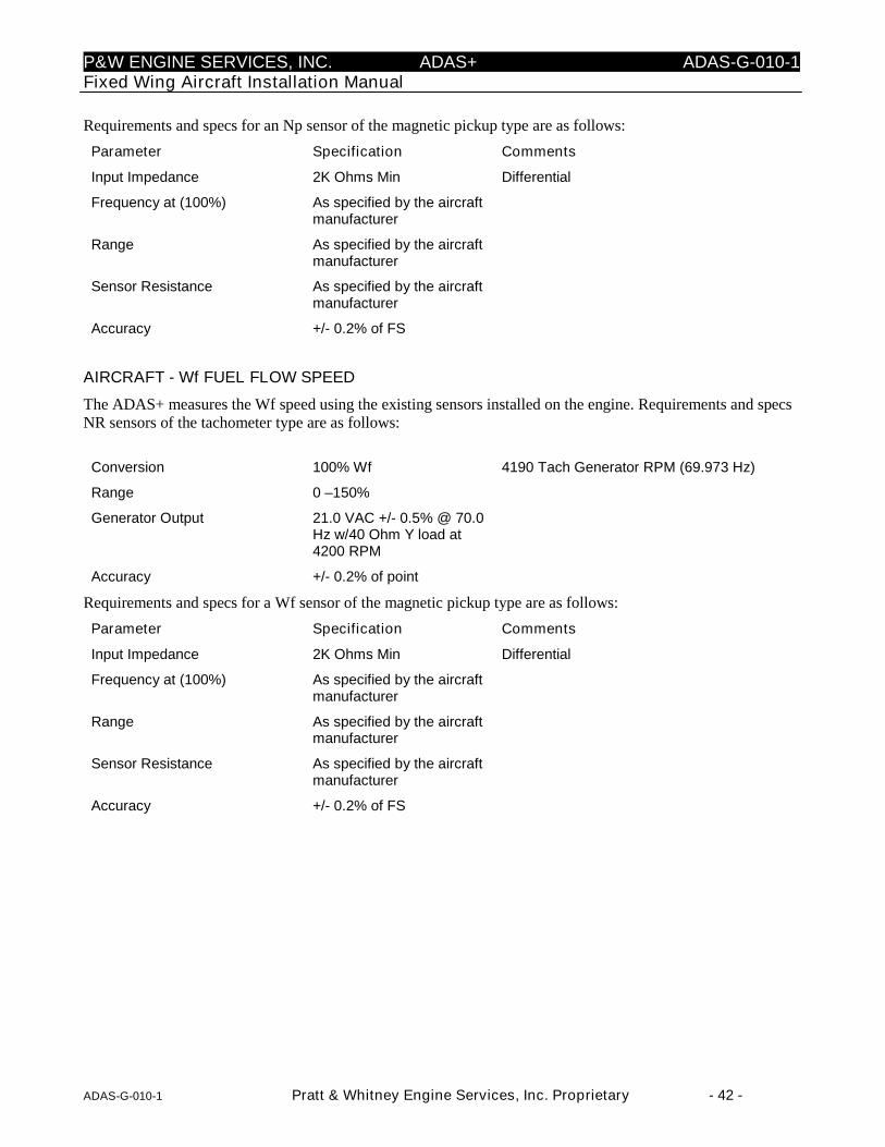
P&W ENGINE SERVICES, INC. ADAS+ ADAS-G-010-1Fixed Wing Aircraft Installation Manual
ADAS-G-010-1 Pratt & Whitney Engine Services, Inc. Proprietary - 42 -
Requirements and specs for an Np sensor of the magnetic pickup type are as follows:
Parameter Specification Comments
Input Impedance 2K Ohms Min Differential
Frequency at (100%) As specified by the aircraftmanufacturer
Range As specified by the aircraftmanufacturer
Sensor Resistance As specified by the aircraftmanufacturer
Accuracy +/- 0.2% of FS
AIRCRAFT - Wf FUEL FLOW SPEED
The ADAS+ measures the Wf speed using the existing sensors installed on the engine. Requirements and specsNR sensors of the tachometer type are as follows:
Conversion 100% Wf 4190 Tach Generator RPM (69.973 Hz)
Range 0 –150%
Generator Output 21.0 VAC +/- 0.5% @ 70.0Hz w/40 Ohm Y load at4200 RPM
Accuracy +/- 0.2% of point
Requirements and specs for a Wf sensor of the magnetic pickup type are as follows:
Parameter Specification Comments
Input Impedance 2K Ohms Min Differential
Frequency at (100%) As specified by the aircraftmanufacturer
Range As specified by the aircraftmanufacturer
Sensor Resistance As specified by the aircraftmanufacturer
Accuracy +/- 0.2% of FS
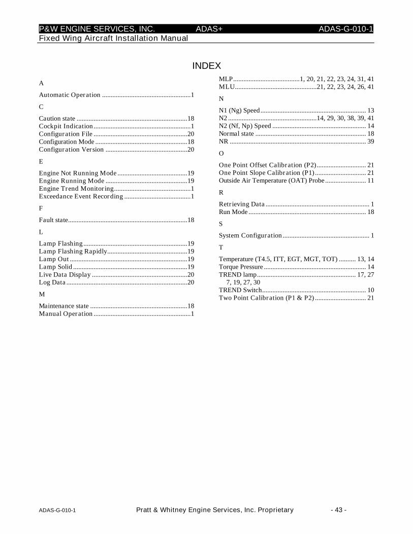
P&W ENGINE SERVICES, INC. ADAS+ ADAS-G-010-1Fixed Wing Aircraft Installation Manual
ADAS-G-010-1 Pratt & Whitney Engine Services, Inc. Proprietary - 43 -
INDEX
A
Automatic Operation ....................................................1
C
Caution state .................................................................18Cockpit Indication.........................................................1Configuration File .......................................................20Configuration Mode ......................................................18Configuration Version ................................................20
E
Engine Not Running Mode .........................................19Engine Running Mode ................................................19Engine Trend Monitoring.............................................1Exceedance Event Recording .......................................1
F
Fault state......................................................................18
L
Lamp Flashing .............................................................19Lamp Flashing Rapidly...............................................19Lamp Out .....................................................................19Lamp Solid ...................................................................19Live Data Display ........................................................20Log Data .......................................................................20
M
Maintenance state .........................................................18Manual Operation .........................................................1
MLP.......................................1, 20, 21, 22, 23, 24, 31, 41MLU................................................21, 22, 23, 24, 26, 41
N
N1 (Ng) Speed.............................................................. 13N2 ....................................................14, 29, 30, 38, 39, 41N2 (Nf, Np) Speed ....................................................... 14Normal state ................................................................. 18NR ................................................................................ 39
O
One Point Offset Calibration (P2) ............................. 21One Point Slope Calibration (P1) .............................. 21Outside Air Temperature (OAT) Probe ........................ 11
R
Retrieving Data ............................................................. 1Run Mode ..................................................................... 18
S
System Configuration................................................... 1
T
Temperature (T4.5, ITT, EGT, MGT, TOT) .......... 13, 14Torque Pressure ............................................................ 14TREND lamp.......................................................... 17, 27
7, 19, 27, 30TREND Switch............................................................. 10Two Point Calibration (P1 & P2) .............................. 21

P&W ENGINE SERVICES, INC. ADAS+ ADAS-G-010-1Fixed Wing Aircraft Installation Manual
ADAS-G-010-1 Pratt & Whitney Engine Services, Inc. Proprietary - 44 -
Glossary of Terms
AC – Alternating current
AFM – Airman’s Flight Manual
EGT – Exhaust Gas Temperature
HSP – Hot Start Prevention
ITT – Inlet Turbine Temperature
Log Data - Stored Operational Readings
LRU – Line Replaceable Unit
MEL– Minimum Equipment List
MGT – Measured Gas Temperature
MLP – Monitor Link Program
MLU – Monitor Link Unit
Nf – Free Turbine
Np – Propeller
Nr Speed – Main Rotor Speed
N1 (Ng) Speed – Low Compressor Rotor Speed
N2 Speed – High Compressor Rotor Speed
OAT – Outside Air Temperature
OEI – One Engine Inoperative
Pa – Ambient Pressure
P/N – Part Number
PRV – Pressure Regulating Valve
P/T – Power Turbine
P1 – One Point Slope Calibration
P2 – One Point Offset Calibration
Ta – Ambient Temperature
TOT – Turbine Outlet Temperature
T4.5 – Power Turbine Inlet Temperature
Wf – Fuel Flow (PPH)
ΔP – Differential Pressure
ΔT – Differential Temperature

P&W ENGINE SERVICES, INC. ADAS+ ADAS-G-010-1/ACessna Caravan Model 208 Series
AADAS-G-010-1/A Pratt & Whitney Engine Services, Inc. Proprietary
ADDENDUM A: ADAS+ Installation Manual for Cessna CaravanModel Series 208

P&W ENGINE SERVICES, INC. ADAS+ ADAS-G-010-1/CRaytheon Model 200, 300, & 1900 Series
BADAS-G-010-1/A Pratt & Whitney Engine Services, Inc. Proprietary
ADDENDUM B: ADAS+ Installation Manual for Raytheon ModelSeries 90

P&W ENGINE SERVICES, INC. ADAS+ ADAS-G-010-1Cessna Caravan Model Series 208
CADAS-G-010-1/A Altair Avionics Proprietary
ADDENDUM C: ADAS+ Installation Manual for Raytheon ModelSeries 200, 300, & 1900

P&W ENGINE SERVICES, INC. ADAS+ ADAS-G-010-1/DEmpresa Brasileira de Aeronautica S. A. (Embraer) Models EMB-110P1/P2
DADAS-G-010-1/D Pratt & Whitney Engine Services, Inc. Proprietary
ADDENDUM D: ADAS+ Installation Manual for Embraer ModelEMB-110P1 and EMB-110P2

P&W ENGINE SERVICES, INC. ADAS+ ADAS-G-010-1/EAir Tractor Models AT-400, 400A, 402, 402A, 402B, 501, 502, 502A, 502B, 503, 503A, 602, 802, 802A
EADAS-G-010-1/E Pratt & Whitney Engine Services, Inc. Proprietary
ADDENDUM E: ADAS+ Installation Manual for Air Tractor ModelsAT-400, 400A, 402, 402A, 402B 501, 502, 502A,502B, 503, 503A, 602, 802, 802A

P&W ENGINE SERVICES, INC. ADAS+ ADAS-G-010-1/FPilatus Model PC-6B & C Series
FADAS-G-010-1/F Pratt & Whitney Engine Services, Inc. Proprietary
ADDENDUM F: ADAS+ Installation Manual for Pilatus Porter ModelPC-6B & C Series


![PRATT & WHITNEY GEARED TURBOFANTM ENGINE FAST …...GoAir selects Pratt & Whitney GTF™ engines to Power 72 Additional Airbus A320neo Family Aircraft [read more] Pratt & Whitney GTF™](https://img.pdfslide.us/doc/110x75/5e6914b9a9534232a97b1b4d/pratt-whitney-geared-turbofantm-engine-fast-goair-selects-pratt-.jpg)