Embed Size (px)
Citation preview
Practical Workbook
Computer Architecture & Organization
Fall 2011
Department of Computer & Information Systems Engineering
NED University of Engineering & Technology,
Karachi – 75270, Pakistan
Name : _____________________________
Year : _____________________________
Batch : _____________________________
Roll No : _____________________________
Department: _____________________________
INTRODUCTION
A course on Computer Architecture and Organization is meant to provide insight into working of
computer systems. There are several reasons for its inclusion in various disciplines. The obvious
objective of studying computer architecture is to learn how to design one. Writing machine
dependent software such as compilers, operating systems, and device drivers, need knowledge of
possible structural and functional organization of computer architectures. A software engineer or
scientific programmer interested in high performance studies computer architecture to learn how to
design programs to gain maximum performance from a given architecture. Working with systems
that involve a variety of interfaces, equipment and communication facilities require knowledge of
computer organization. Last, but not least, understanding cost/performance trade-offs in a computer
system which result from design and implementation decisions can be achieved through
understanding of computer architecture.
This laboratory workbook is developed to strengthen topics covered in theory classes. There are two
major parts in this workbook: Part – I contains assembly language programming for x86 processors,
used in desktops and laptops. This will enable the students to grasp low-level programming details
of commonly used machines. Visual Studio has been used as programming environment. Part – II
explores, in depth, assembly language of MIPS processor, an essential component of many
embedded systems. SPIM, a freely available MIPS simulator has been used to this end. Thus,
students get an opportunity of learning assembly language of both CISC (x86) and RISC (MIPS)
machines. Two labs are devoted to description of cache and virtual memory operations.
The lab sessions are intended to be thought provoking so that students can think out-of-the- box and
have their own way of solving a problem rather than following the traditional footsteps. This is what
makes the most exciting area of Computer Architecture & Organization!
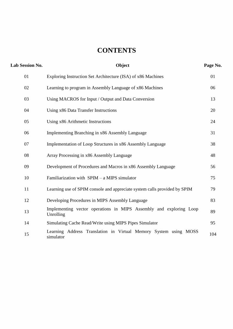
CONTENTS
Lab Session No. Object Page No.
01 Exploring Instruction Set Architecture (ISA) of x86 Machines 01
02 Learning to program in Assembly Language of x86 Machines 06
03 Using MACROS for Input / Output and Data Conversion 13
04 Using x86 Data Transfer Instructions 20
05 Using x86 Arithmetic Instructions 24
06 Implementing Branching in x86 Assembly Language 31
07 Implementation of Loop Structures in x86 Assembly Language 38
08 Array Processing in x86 Assembly Language 48
09 Development of Procedures and Macros in x86 Assembly Language 56
10 Familiarization with SPIM – a MIPS simulator 75
11 Learning use of SPIM console and appreciate system calls provided by SPIM 79
12 Developing Procedures in MIPS Assembly Language 83
13 Implementing vector operations in MIPS Assembly and exploring Loop
Unrolling 89
14 Simulating Cache Read/Write using MIPS Pipes Simulator 95
15 Learning Address Translation in Virtual Memory System using MOSS
simulator 104
Computer Architecture & Organization Lab Session 01 NED University of Engineering & Technology – Department of Computer & Information Systems Engineering
1
Lab Session 01 1. OBJECT
Exploring Instruction Set Architecture (ISA) of x86 Machines.
2. THEORY
2.1 Instruction Set Architecture (ISA)
The ISA of a machine is the set of its attributes a system programmer needs to know in order to develop system
software or a complier requires for translation of a High Level Language (HLL) code into machine language.
Examples of such attributes are (but not limited to):
Instruction Set
Programmer Accessible Registers - these are the general purpose registers (GPR) within a processor in contrast
to some special purpose registers only accessible to the system hardware and Operating System (OS)
Memory-Processor Interaction
Addressing Modes - means of specifying operands in an instruction (e.g. immediate mode, direct mode, indirect
mode, etc )
Instruction Formats – breakup of an instruction into various fields (e.g. opcode, specification of source and
destination operands, etc)
ISA is also known as the programmer’s view or software model of the machine.
2.2 ISA of x86 Machines
From its onset in 1978, x86 ISA has been the most dominant in desktops and laptops. This represents a
family of machines beginning with 16-bit 8086/8088 microprocessors. (An n-bit microprocessor is
capable of performing n-bit operations). As an evolutionary process, Intel continued to add capabilities
and features to this basic ISA. The 80386 was the first 32-bit processor of the family. The ISA of 32-bit
processor is regarded as IA-32 (IA for Intel Architecture) or x86-32 by Intel. IA-64 was introduced in
Pentium-4F and later processors. Operating Systems are now also categorized on the basis of the
architecture they can run on. A 64-bit OS can execute both 64-bit and 32-bit applications. We will limit
scope of our discussion to IA-32.
2.2.1 Registers
Registers are storage locations inside the processor. A register can be accessed more quickly than a memory
location. Different registers serve different purposes. Some of them are described below:
2.2.1.1 General-Purpose Registers
EAX, EBX, ECX and EDX are called data or general purpose registers. (E is for extended as they are 32-bit
extensions of their 16-bit counter parts AX, BX, CX and DX in 16-bit ISA). The register EAX is also known as
accumulator because it is used as destination in many arithmetic operations. Some instructions generate more
efficient code if they reference the EAX register rather than other registers.
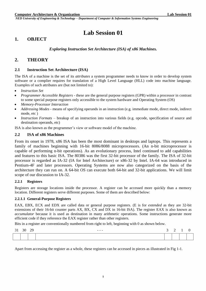
Bits in a register are conventionally numbered from right to left, beginning with 0 as shown below.
31 30 29 - - - 3 2 1 0
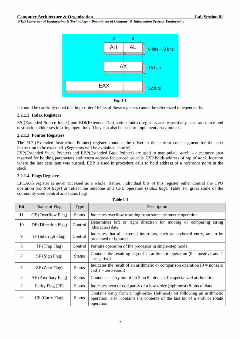
Apart from accessing the register as a whole, these registers can be accessed in pieces as illustrated in Fig 1-1.
Computer Architecture & Organization Lab Session 01 NED University of Engineering & Technology – Department of Computer & Information Systems Engineering
2
Fig. 1-1
It should be carefully noted that high-order 16 bits of these registers cannot be referenced independently.
2.2.1.2 Index Registers
ESI(Extended Source Index) and EDI(Extended Destination Index) registers are respectively used as source and
destination addresses in string operations. They can also be used to implement array indices.
2.2.1.3 Pointer Registers
The EIP (Extended Instruction Pointer) register contains the offset in the current code segment for the next
instruction to be executed. (Segments will be explained shortly).
ESP(Extended Stack Pointer) and EBP(Extended Base Pointer) are used to manipulate stack - a memory area
reserved for holding parameters and return address for procedure calls. ESP holds address of top of stack, location
where the last data item was pushed. EBP is used in procedure calls to hold address of a reference point in the
stack.
2.2.1.4 Flags Register
EFLAGS register is never accessed as a whole. Rather, individual bits of this register either control the CPU
operation (control flags) or reflect the outcome of a CPU operation (status flag). Table 1-1 gives some of the
commonly used control and status flags.
Table 1-1
Bit Name of Flag Type Description
11 OF (Overflow Flag) Status Indicates overflow resulting from some arithmetic operation
10 DF (Direction Flag) Control Determines left or right direction for moving or comparing string
(character) data.
9 IF (Interrupt Flag) Control Indicates that all external interrupts, such as keyboard entry, are to be
processed or ignored.
8 TF (Trap Flag) Control Permits operation of the processor in single-step mode.
7 SF (Sign Flag) Status Contains the resulting sign of an arithmetic operation (0 = positive and 1
= negative).
6 ZF (Zero Flag) Status Indicates the result of an arithmetic or comparison operation (0 = nonzero
and 1 = zero result)
4 AF (Auxiliary Flag) Status Contains a carry out of bit 3 on 8–bit data, for specialized arithmetic.
2 Parity Flag (PF) Status Indicates even or odd parity of a low-order (rightmost) 8-bits of data
0 CF (Carry Flag) Status Contains carry from a high-order (leftmost) bit following an arithmetic
operation; also, contains the contents of the last bit of a shift or rotate
operation.
AH AL
16 bits
8
AX
EAX
8
32 bits
8 bits + 8 bits
Computer Architecture & Organization Lab Session 01 NED University of Engineering & Technology – Department of Computer & Information Systems Engineering
3
2.2.2 Memory Addressing
A 32-bit processor uses 32-bit addresses and thus can access 232
B = 4GB physical memory. Depending on the
machine, a processor can access one or more bytes from memory at a time. The number of bytes accessed
simultaneously from main memory is called word length of machine.
Generally, all machines are byte-addressable i.e.; every byte stored in memory has a unique address. However,
word length of a machine is typically some integral multiple of a byte. Therefore, the address of a word must be the
address of one of its constituting bytes. In this regard, one of the following methods of addressing (also known as
byte ordering) may be used.
Big Endian – the higher byte is stored at lower memory address (i.e. Big Byte first). MIPS, Apple, Sun SPARC are
some of the machines in this class.
Little Endian - the lower byte is stored at lower memory address (i.e. Little Byte first). Intel’s machines use little
endian.
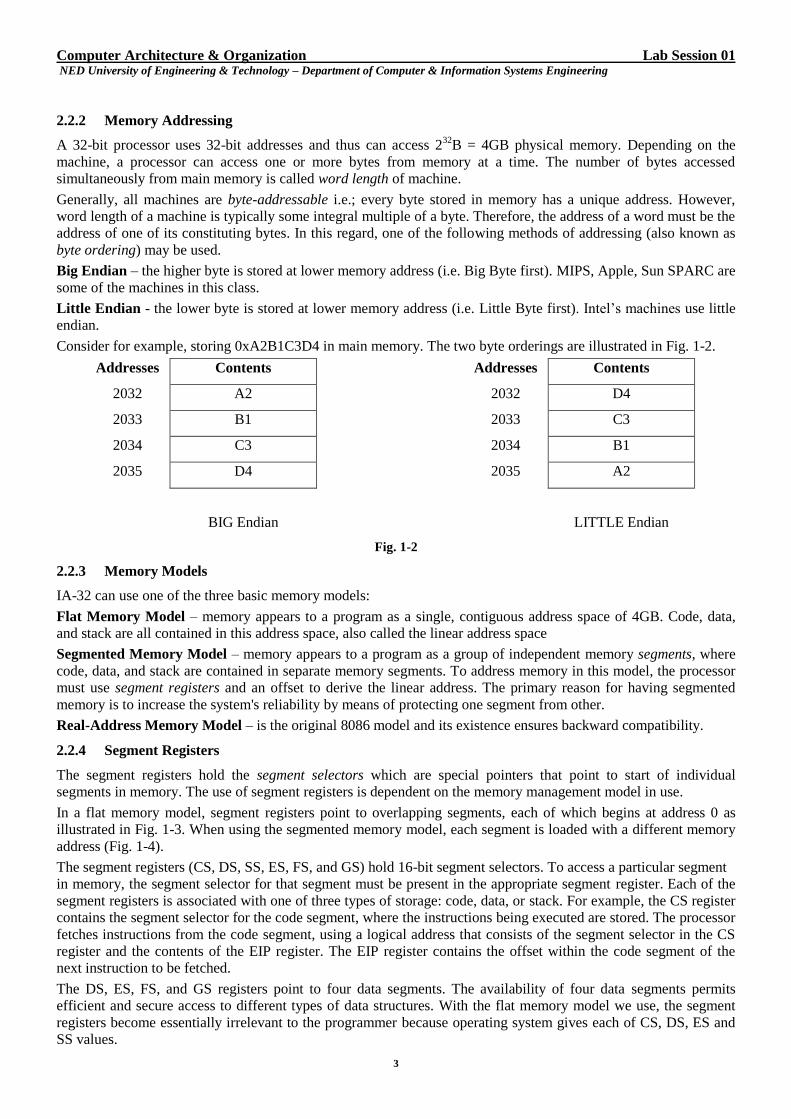
Consider for example, storing 0xA2B1C3D4 in main memory. The two byte orderings are illustrated in Fig. 1-2.
Addresses Contents Addresses Contents
2032 A2 2032 D4
2033 B1 2033 C3
2034 C3 2034 B1
2035 D4 2035 A2
BIG Endian LITTLE Endian
Fig. 1-2
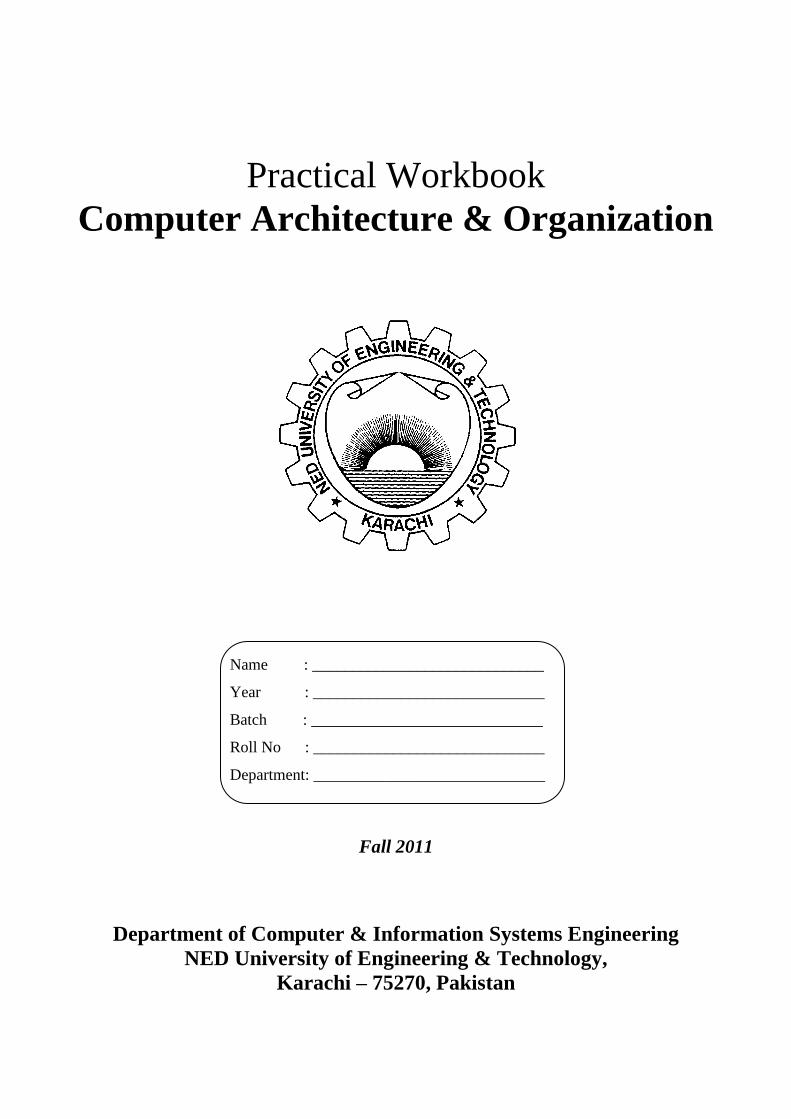
2.2.3 Memory Models
IA-32 can use one of the three basic memory models:
Flat Memory Model – memory appears to a program as a single, contiguous address space of 4GB. Code, data,
and stack are all contained in this address space, also called the linear address space
Segmented Memory Model – memory appears to a program as a group of independent memory segments, where
code, data, and stack are contained in separate memory segments. To address memory in this model, the processor
must use segment registers and an offset to derive the linear address. The primary reason for having segmented
memory is to increase the system's reliability by means of protecting one segment from other.
Real-Address Memory Model – is the original 8086 model and its existence ensures backward compatibility.
2.2.4 Segment Registers
The segment registers hold the segment selectors which are special pointers that point to start of individual
segments in memory. The use of segment registers is dependent on the memory management model in use.
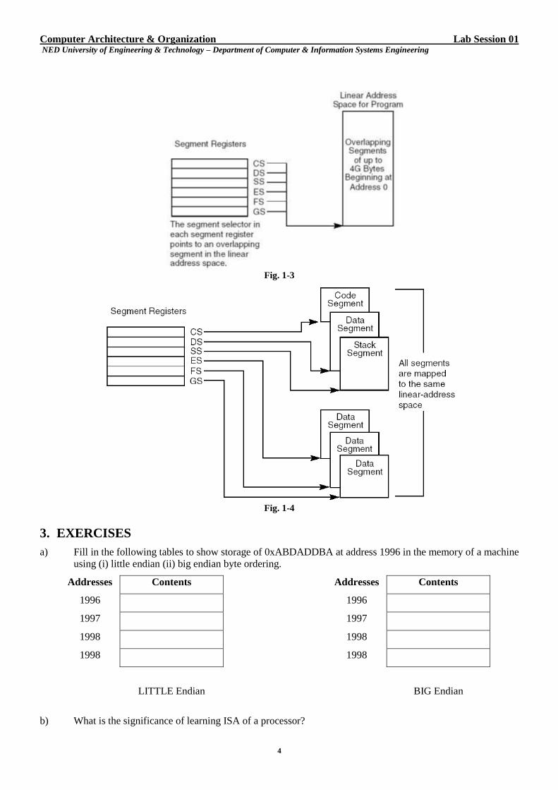
In a flat memory model, segment registers point to overlapping segments, each of which begins at address 0 as
illustrated in Fig. 1-3. When using the segmented memory model, each segment is loaded with a different memory
address (Fig. 1-4).
The segment registers (CS, DS, SS, ES, FS, and GS) hold 16-bit segment selectors. To access a particular segment
in memory, the segment selector for that segment must be present in the appropriate segment register. Each of the
segment registers is associated with one of three types of storage: code, data, or stack. For example, the CS register
contains the segment selector for the code segment, where the instructions being executed are stored. The processor
fetches instructions from the code segment, using a logical address that consists of the segment selector in the CS
register and the contents of the EIP register. The EIP register contains the offset within the code segment of the
next instruction to be fetched.
The DS, ES, FS, and GS registers point to four data segments. The availability of four data segments permits
efficient and secure access to different types of data structures. With the flat memory model we use, the segment
registers become essentially irrelevant to the programmer because operating system gives each of CS, DS, ES and
SS values.
Computer Architecture & Organization Lab Session 01 NED University of Engineering & Technology – Department of Computer & Information Systems Engineering
4
Fig. 1-3
Fig. 1-4
3. EXERCISES
a) Fill in the following tables to show storage of 0xABDADDBA at address 1996 in the memory of a machine
using (i) little endian (ii) big endian byte ordering.
Addresses Contents Addresses Contents
1996 1996
1997 1997
1998 1998
1998 1998
LITTLE Endian BIG Endian
b) What is the significance of learning ISA of a processor?
Computer Architecture & Organization Lab Session 01 NED University of Engineering & Technology – Department of Computer & Information Systems Engineering
5
c) Show the ECX register and the size and position of the CH, CL, and CX within it.
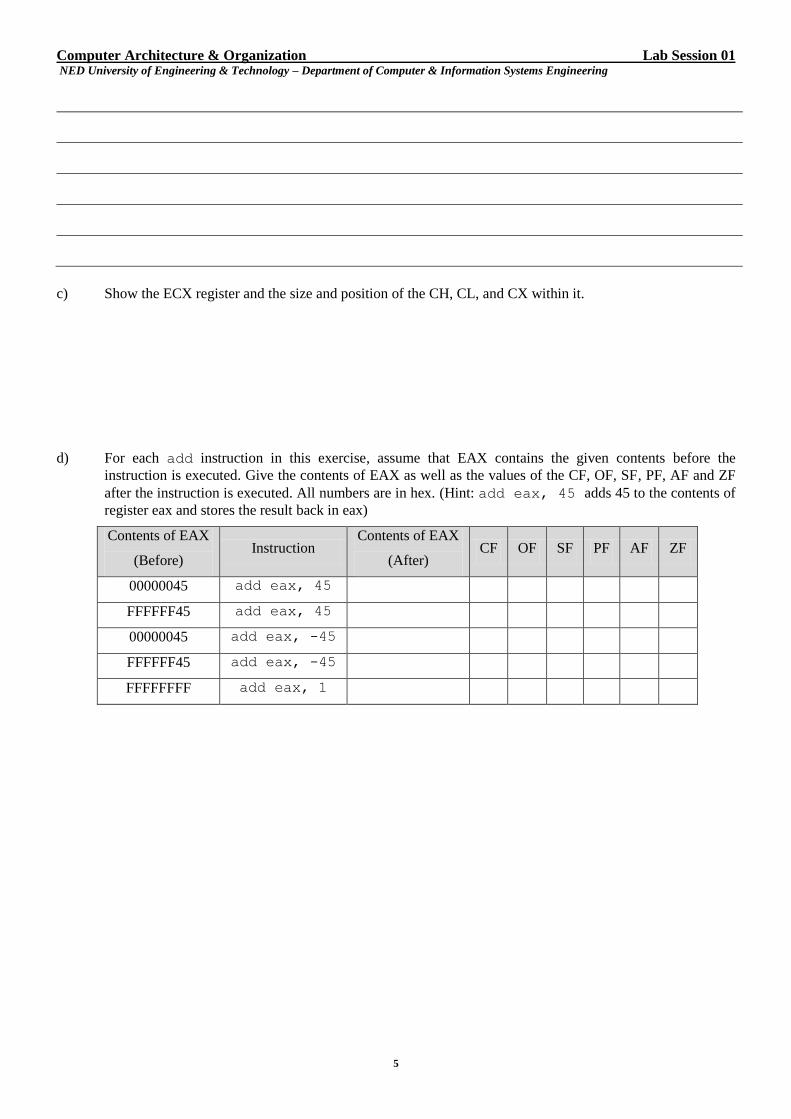
d) For each add instruction in this exercise, assume that EAX contains the given contents before the
instruction is executed. Give the contents of EAX as well as the values of the CF, OF, SF, PF, AF and ZF
after the instruction is executed. All numbers are in hex. (Hint: add eax, 45 adds 45 to the contents of
register eax and stores the result back in eax)
Contents of EAX
(Before) Instruction
Contents of EAX
(After) CF OF SF PF AF ZF
00000045 add eax, 45
FFFFFF45 add eax, 45
00000045 add eax, -45
FFFFFF45 add eax, -45
FFFFFFFF add eax, 1
Computer Architecture & Organization Lab Session 02 NED University of Engineering & Technology – Department of Computer & Information Systems Engineering
6
Lab Session 02 1. OBJECT
Learning to program in Assembly Language of x86 Machines.
2. THEORY
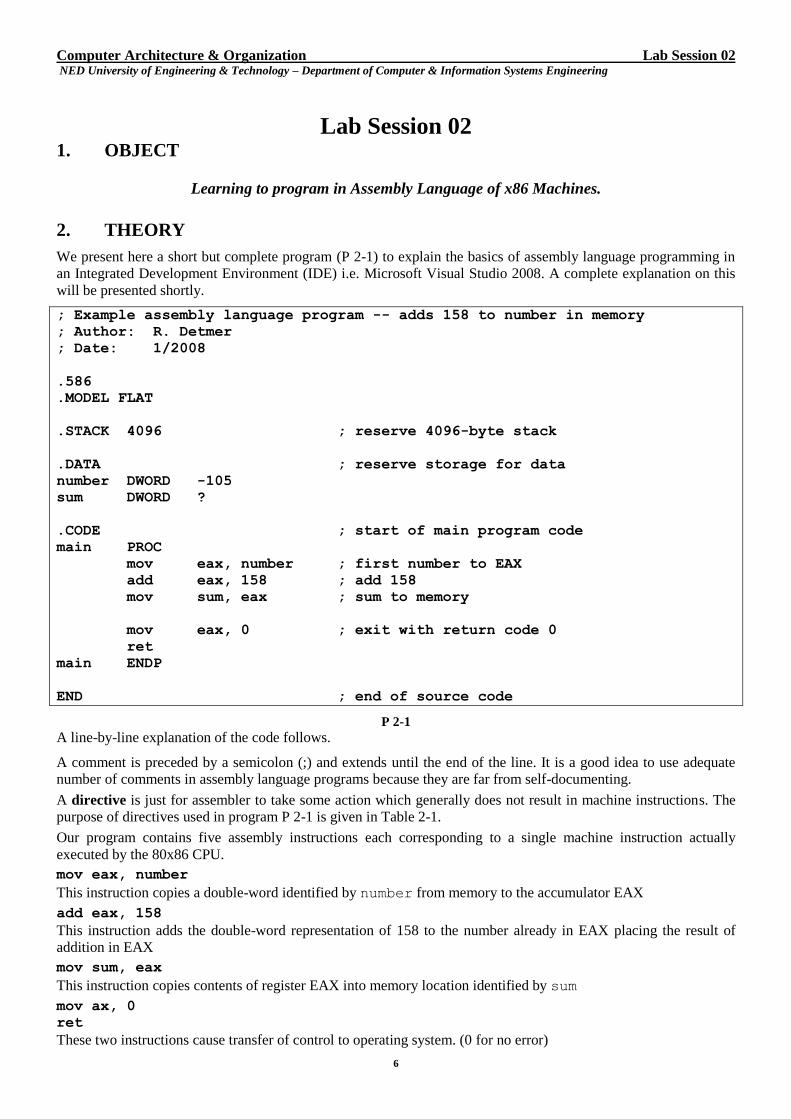
We present here a short but complete program (P 2-1) to explain the basics of assembly language programming in
an Integrated Development Environment (IDE) i.e. Microsoft Visual Studio 2008. A complete explanation on this
will be presented shortly.
; Example assembly language program -- adds 158 to number in memory
; Author: R. Detmer
; Date: 1/2008
.586
.MODEL FLAT
.STACK 4096 ; reserve 4096-byte stack
.DATA ; reserve storage for data
number DWORD -105
sum DWORD ?
.CODE ; start of main program code
main PROC
mov eax, number ; first number to EAX
add eax, 158 ; add 158
mov sum, eax ; sum to memory
mov eax, 0 ; exit with return code 0
ret
main ENDP
END ; end of source code
P 2-1
A line-by-line explanation of the code follows.
A comment is preceded by a semicolon (;) and extends until the end of the line. It is a good idea to use adequate
number of comments in assembly language programs because they are far from self-documenting.
A directive is just for assembler to take some action which generally does not result in machine instructions. The
purpose of directives used in program P 2-1 is given in Table 2-1.
Our program contains five assembly instructions each corresponding to a single machine instruction actually
executed by the 80x86 CPU.
mov eax, number
This instruction copies a double-word identified by number from memory to the accumulator EAX
add eax, 158
This instruction adds the double-word representation of 158 to the number already in EAX placing the result of
addition in EAX
mov sum, eax
This instruction copies contents of register EAX into memory location identified by sum
mov ax, 0
ret
These two instructions cause transfer of control to operating system. (0 for no error)
Computer Architecture & Organization Lab Session 02 NED University of Engineering & Technology – Department of Computer & Information Systems Engineering
7
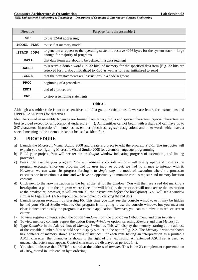
Directive Purpose (tells the assembler)
.586 to use 32-bit addressing
.MODEL FLAT to use flat memory model
.STACK 4096 to generate a request to the operating system to reserve 4096 bytes for the system stack - large
enough for majority of programs
.DATA that data items are about to be defined in a data segment
DWORD to reserve a double-word (i.e. 32 bits) of memory for the specified data item [E.g. 32 bits are
reserved for number initialized to -105 as well as for sum initialized to zero]
.CODE that the next statements are instructions in a code segment
PROC beginning of a procedure
ENDP end of a procedure
END to stop assembling statements
Table 2-1
Although assembler code is not case-sensitive but it’s a good practice to use lowercase letters for instructions and
UPPERCASE letters for directives.
Identifiers used in assembly language are formed from letters, digits and special characters. Special characters are
best avoided except for an occasional underscore ( _ ). An identifier cannot begin with a digit and can have up to
247 characters. Instructions' mnemonics, assembler directives, register designations and other words which have a
special meaning to the assembler cannot be used as identifier.
3. PROCEDURE
a) Launch the Microsoft Visual Studio 2008 and create a project to edit the program P 2-1. The instructor will
explain you configuring Microsoft Visual Studio 2008 for assembly language programming.
b) Build your project. You will see text in an Output window indicating progress of assembling and linking
processes.
c) Press F5to execute your program. You will observe a console window will briefly open and close as the
program executes. Since our program had no user input or output, we had no chance to interact with it.
However, we can watch its progress forcing it to single step – a mode of execution wherein a processor
executes one instruction at a time and we have an opportunity to monitor various register and memory location
contents.
d) Click next to the mov instruction in the bar at the left of the window. You will then see a red dot marking a
breakpoint, a point in the program where execution will halt (i.e. the processor will not execute the instruction
at the breakpoint; however, it will execute all the instructions before the breakpoint). You will see a window
similar to Figure 2-1. (A breakpoint can be removed by clicking the red dot)
e) Launch program execution by pressing F5. This time you may see the console window, or it may be hidden
behind your Visual Studio window. Our program is not going to use the console window, but you must not
close it since technically the program is a console application. However, you can minimize it to reduce screen
clutter.
f) To view register contents, select the option Windows from the drop-down Debug menu and then Registers.
g) To view memory contents, repeat the option Debug-Windows option, selecting Memory and then Memory 1.
h) Type &number in the Address box of Memory 1 window. This will display the memory starting at the address
of the variable number. You should see a display similar to the one in Fig. 2-2. The Memory 1 window shows
hex contents of memory stored at address of number. For each byte having an interpretation as a printable
ASCII character, that character is shown to the right of the hex listing. An extended ASCII set is used, so
unusual characters may appear. Control characters are displayed as periods (…).
i) You should observe that 97ffffff is stored at the address of number. This is the 2's complement representation
of -10510 stored in little endian byte ordering.
Computer Architecture & Organization Lab Session 02 NED University of Engineering & Technology – Department of Computer & Information Systems Engineering
8
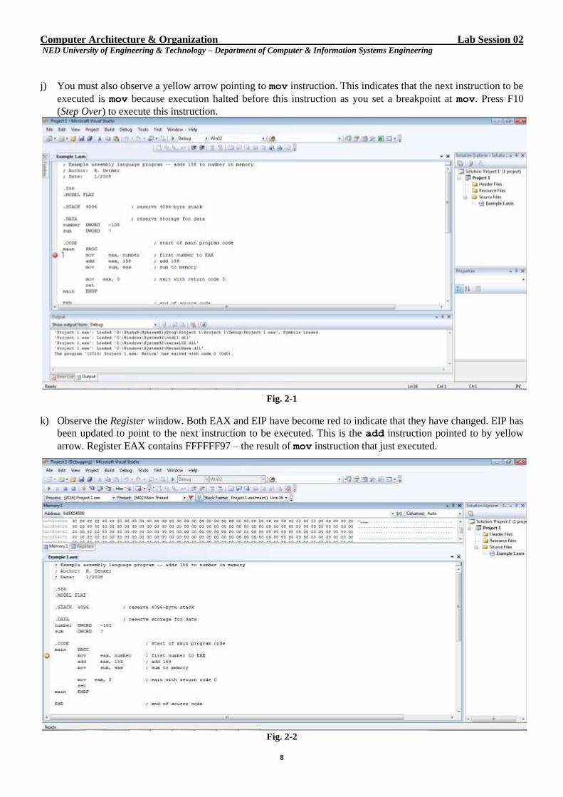
j) You must also observe a yellow arrow pointing to mov instruction. This indicates that the next instruction to be
executed is mov because execution halted before this instruction as you set a breakpoint at mov. Press F10
(Step Over) to execute this instruction.
Fig. 2-1
k) Observe the Register window. Both EAX and EIP have become red to indicate that they have changed. EIP has
been updated to point to the next instruction to be executed. This is the add instruction pointed to by yellow
arrow. Register EAX contains FFFFFF97 – the result of mov instruction that just executed.
Fig. 2-2
Computer Architecture & Organization Lab Session 02 NED University of Engineering & Technology – Department of Computer & Information Systems Engineering
9
l) Press F10 again. You must observe that EFL (EFLAGS) also becomes red along with EAX and EIP. EAX now
contains 00000035 (i.e. the sum of -10510 and 15810) – the result of add instruction that just executed. As
before, the yellow arrow points to the next instruction to be executed that is the mov instruction. (The contents
of EFL will be examined in Exercise (a)).
m) Press F10 again. The program is now ready to execute the last two instructions. These instructions will return
control to the calling program (operating system in this case). Returning 0 value indicates no error. You should
not use F10 to step through these instructions as no debug code is available.
n) Press F5 to complete the execution of this program. You will observe that Console, as well as Registers and
Memory 1 window close.
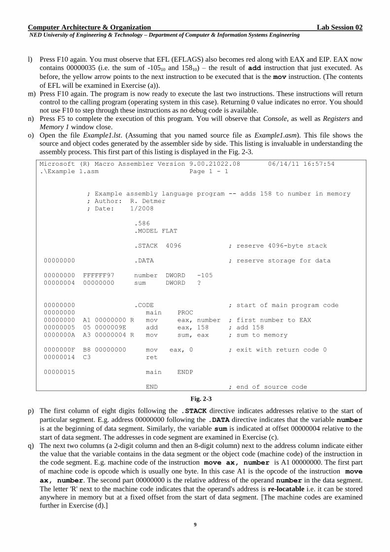
o) Open the file Example1.lst. (Assuming that you named source file as Example1.asm). This file shows the
source and object codes generated by the assembler side by side. This listing is invaluable in understanding the
assembly process. This first part of this listing is displayed in the Fig. 2-3.
Microsoft (R) Macro Assembler Version 9.00.21022.08 06/14/11 16:57:54
.\Example 1.asm Page 1 - 1
; Example assembly language program -- adds 158 to number in memory
; Author: R. Detmer
; Date: 1/2008
.586
.MODEL FLAT
.STACK 4096 ; reserve 4096-byte stack
00000000 .DATA ; reserve storage for data
00000000 FFFFFF97 number DWORD -105
00000004 00000000 sum DWORD ?
00000000 .CODE ; start of main program code
00000000 main PROC
00000000 A1 00000000 R mov eax, number ; first number to EAX
00000005 05 0000009E add eax, 158 ; add 158
0000000A A3 00000004 R mov sum, eax ; sum to memory
0000000F B8 00000000 mov eax, 0 ; exit with return code 0
00000014 C3 ret
00000015 main ENDP
END ; end of source code
Fig. 2-3
p) The first column of eight digits following the .STACK directive indicates addresses relative to the start of
particular segment. E.g. address 00000000 following the .DATA directive indicates that the variable number
is at the beginning of data segment. Similarly, the variable sum is indicated at offset 00000004 relative to the
start of data segment. The addresses in code segment are examined in Exercise (c).
q) The next two columns (a 2-digit column and then an 8-digit column) next to the address column indicate either
the value that the variable contains in the data segment or the object code (machine code) of the instruction in
the code segment. E.g. machine code of the instruction move ax, number is A1 00000000. The first part
of machine code is opcode which is usually one byte. In this case A1 is the opcode of the instruction move
ax, number. The second part 00000000 is the relative address of the operand number in the data segment.
The letter 'R' next to the machine code indicates that the operand's address is re-locatable i.e. it can be stored
anywhere in memory but at a fixed offset from the start of data segment. [The machine codes are examined
further in Exercise (d).]
Computer Architecture & Organization Lab Session 02 NED University of Engineering & Technology – Department of Computer & Information Systems Engineering
10
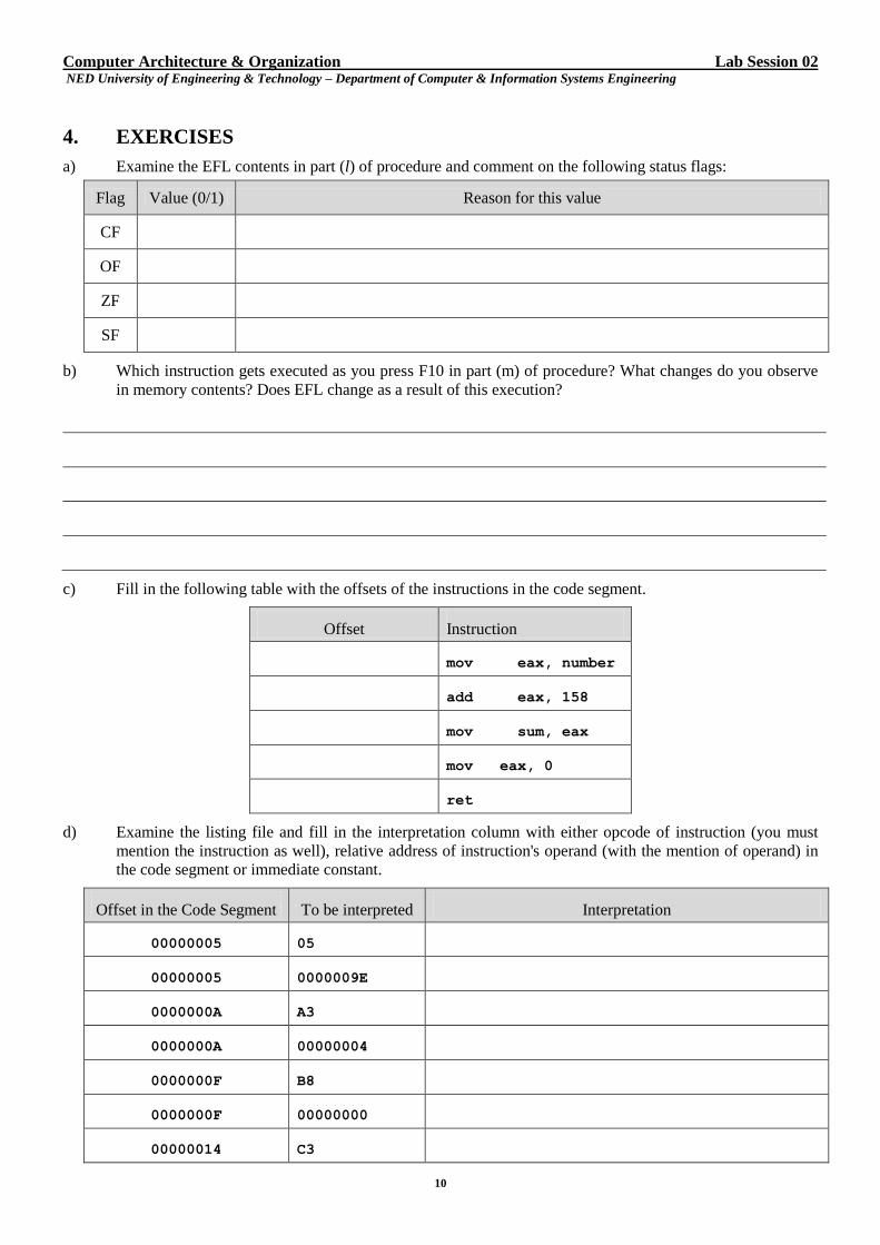
4. EXERCISES
a) Examine the EFL contents in part (l) of procedure and comment on the following status flags:
Flag Value (0/1) Reason for this value
CF
OF
ZF
SF
b) Which instruction gets executed as you press F10 in part (m) of procedure? What changes do you observe
in memory contents? Does EFL change as a result of this execution?
c) Fill in the following table with the offsets of the instructions in the code segment.
Offset Instruction
mov eax, number
add eax, 158
mov sum, eax
mov eax, 0
ret
d) Examine the listing file and fill in the interpretation column with either opcode of instruction (you must
mention the instruction as well), relative address of instruction's operand (with the mention of operand) in
the code segment or immediate constant.
Offset in the Code Segment To be interpreted Interpretation
00000005 05
00000005 0000009E
0000000A A3
0000000A 00000004
0000000F B8
0000000F 00000000
00000014 C3
Computer Architecture & Organization Lab Session 02 NED University of Engineering & Technology – Department of Computer & Information Systems Engineering
11
e) Modify the program P 2-1 to change the value of the number to -25010, and the second instruction to add
7410 to the number in EAX. (The default number system used by assembler is decimal). Assemble, link and
execute the program. Explain the changes that are displayed in registers and memory after execution of
each instruction. (Write your program in the space provided below or attach a printout).
Computer Architecture & Organization Lab Session 02 NED University of Engineering & Technology – Department of Computer & Information Systems Engineering
12
f) Modify the program P 2-1 to add two numbers stored in memory as number1 and number2. (Hint: copy
number1 to EAX and then use an appropriate add instruction). Continue to store the total in sum.
Assemble, link and execute the program. Explain the changes that are displayed in registers and memory
after execution of each instruction. (Write your program in the space provided below or attach a printout).
Computer Architecture & Organization Lab Session 03 NED University of Engineering & Technology – Department of Computer & Information Systems Engineering
13
Lab Session 03 1. OBJECT
Using MACROS for Input / Output and Data Conversion
2. THEORY
A macro is shorthand for a sequence of statements – instructions, directives or even other macros. The assembler
expands a macro to the statements it represents, and then assembles these new statements. The assembly language
program in this lab session will use macros for input / output and conversion of data from ASCII to numeric and
vice versa. However, you must understand data declarations and some addressing modes before delving into that
coding.
2.1 Data Declarations
The default number system used by the assembler is decimal. Using other number systems entail appropriate
suffixes as shown below:
Number System Suffix
Binary B
Hexadecimal H
Octal O or Q
Decimal None
A hexadecimal value must start with a digit. For example, code 0a8h rather than a8h to get a constant with value
A816. The assembler will interpret a8h as a name.
2.1.1 BYTE Directive
This reserves storage for one or more bytes of data, optionally initializing storage. Numeric data can be thought of
as signed in 2's complement notation (-128 to 127) or unsigned (0 to 255). The assembler will generate an error for
BYTE directive with a numeric operand outside these ranges (-128 to 255). Characters are assembled to ASCII
codes. Here are some examples:
byte1 BYTE 255 ; value is FF
byte2 BYTE 91 ; value is 5B
byte3 BYTE 0 ; value is 00
byte4 BYTE -1 ; value is FF
byte5 BYTE 6 DUP (?) ; 6 bytes each with 00
DUP is duplicate operator.
In addition to numeric operands, the BYTE directive allows character operands with a single character or string
operands with multiple characters. Either apostrophe ( ' ) or a quotation marks ( " ) can be used to delimit character
or strings but they should be used in pairs i.e. you cannot put an apostrophe on the left and a quotation mark on the
right. A string delimited with apostrophes can contain quotation marks, and one delimited with quotation marks can
contain apostrophes. We use the convention of putting single characters between apostrophes and strings between
quotation marks.
char BYTE 'm' ; value is 6D (ASCII code of m) string1 BYTE "Joe" ; 3 bytes with 4A 6F 65
string1 BYTE "Joe's" ; 3 bytes with 4A 6F 65 27 73
The situation for WORD, DWORD and QWORD directives is similar. Each operand of WORD directive is stored
in a word (16 bits), DWORD in a double-word (32 bits) and QWORD in a quad-word (64 bits). Double-words are
usually the best choice for integers.
Computer Architecture & Organization Lab Session 03 NED University of Engineering & Technology – Department of Computer & Information Systems Engineering
14
2.1.2 DWORD Directive
Here are some examples:
double1 DWORD -1 ; value is FFFFFFFF
double2 DWORD -1000 ; value is FFFFFC18
double3 DWORD -2147483648 ; value is 80000000
double4 DWORD 0, 1 ; two double-words
double5 DWORD 100 DUP (?) ; 100 double-words initialized to 0
These directives may have multiple operands separated by commas. For example,
dwords DWORD 10, 20, 30, 40
reserves four double-words of storage with initial values as specified.
These directives may have arithmetic operations as their operands. An example follows:
double1 DWORD 12*12
2.1.3 Other Directives
Directive Description
TBYTE reserves a 10-byte integer
REAL4 reserves a 4-byte floating-point
REAL8 reserves an 8-byte floating-point
REAL10 reserves a 10-byte floating-point
2.2 Addressing Modes
We have already seen immediate (operand is part of instruction) and register direct (operand is in specified
register) addressing modes in program P 2-1. Let's discuss direct and register indirect addressing modes.
In direct addressing mode, operand's address is part of instruction. For example, the instruction mov sum, eax
from program P 2-1 uses register-direct mode for eax and direct addressing mode for sum. In assembly language,
any memory reference coded as just a name will be direct.
In register-indirect addressing mode, the specified register (surrounded by square brackets [ ]) contains operand's
address. For example, the instruction add eax, [edx]adds an operand pointed to by edx to the contents of
eax and puts the result in eax. However, when size of memory operand is ambiguous, the PTR operator must be
used to give its size to assembler. For example, mov [ebx], 0 will generate an error because it cannot be
ascertained whether the destination is a byte, word, double-word, or quad-word. If it is a byte, you should use the
instruction as mov BYTE PTR [ebx], 0. This is valid for WORD, DWORD and QWORD directives as well.
In an instruction like add eax, [edx], it is not necessary to use DWORD PTR [edx] because the assembler
assumes that the source will be double-word as the destination eax is double-word.
3. PROGRAM
a) Launch the Microsoft Visual Studio 2008 and open the windows32 project which contains three source files.
We first concentrate on example.asm shown below (P 3-1). The header file io.h contains descriptions of
the macros that are used for I/O and for conversion between ASCII and integer formats.
b) In data segment each string is NULL terminated.
c) The code framework we are using is a C program whose execution starts with function main. This framework
is designed to always call _MainProc, which is therefore the name of our assembly language procedure.
Procedure calls will be explored in depth in a later lab session.
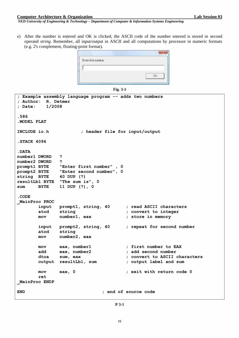
d) The statement input prompt1, string, 40 ; read ASCII characters
is a macro with three operands. It expands to instructions that call a procedure to display a Windows dialog box
that looks like Fig. 3-1. The first operand specifies the label that appears in the dialog box. In this case it is a
string in memory pointed to by prompt1.
Computer Architecture & Organization Lab Session 03 NED University of Engineering & Technology – Department of Computer & Information Systems Engineering
15
e) After the number is entered and OK is clicked, the ASCII code of the number entered is stored in second
operand string. Remember, all input/output in ASCII and all computations by processor in numeric formats
(e.g. 2's complement, floating-point format).
Fig. 3-1
; Example assembly language program -- adds two numbers
; Author: R. Detmer
; Date: 1/2008
.586
.MODEL FLAT
INCLUDE io.h ; header file for input/output
.STACK 4096
.DATA
number1 DWORD ?
number2 DWORD ?
prompt1 BYTE "Enter first number" , 0
prompt2 BYTE "Enter second number", 0
string BYTE 40 DUP (?)
resultLbl BYTE "The sum is", 0
sum BYTE 11 DUP (?), 0
.CODE
_MainProc PROC
input prompt1, string, 40 ; read ASCII characters
atod string ; convert to integer
mov number1, eax ; store in memory
input prompt2, string, 40 ; repeat for second number
atod string
mov number2, eax
mov eax, number1 ; first number to EAX
add eax, number2 ; add second number
dtoa sum, eax ; convert to ASCII characters
output resultLbl, sum ; output label and sum
mov eax, 0 ; exit with return code 0
ret
_MainProc ENDP
END ; end of source code
P 3-1
Computer Architecture & Organization Lab Session 03 NED University of Engineering & Technology – Department of Computer & Information Systems Engineering
16
f) The third operand of the macro is length of string as specified in the data segment. The length has been taken
long enough to hold a reasonable number.
g) The next macro in the program atod string
converts its single operand string (ASCII format) to double-word integer (numeric) and hence the name atod.
It actually expands to instructions that call a procedure to scans the string and converts the ASCII
representation to 2's complement double-word integer and stores in EAX – no other destination is allowed.
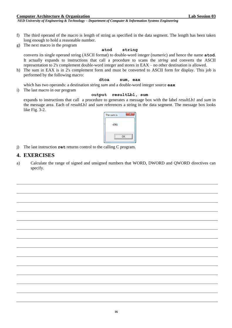
h) The sum in EAX is in 2's complement form and must be converted to ASCII form for display. This job is
performed by the following macro: dtoa sum, eax
which has two operands: a destination string sum and a double-word integer source eax
i) The last macro in our program output resultLbl, sum
expands to instructions that call a procedure to generates a message box with the label resultLb1 and sum in
the message area. Each of resultLb1 and sum references a string in the data segment. The message box looks
like Fig. 3-2.
j) The last instruction ret returns control to the calling C program.
4. EXERCISES
a) Calculate the range of signed and unsigned numbers that WORD, DWORD and QWORD directives can
specify.
Computer Architecture & Organization Lab Session 03 NED University of Engineering & Technology – Department of Computer & Information Systems Engineering
17
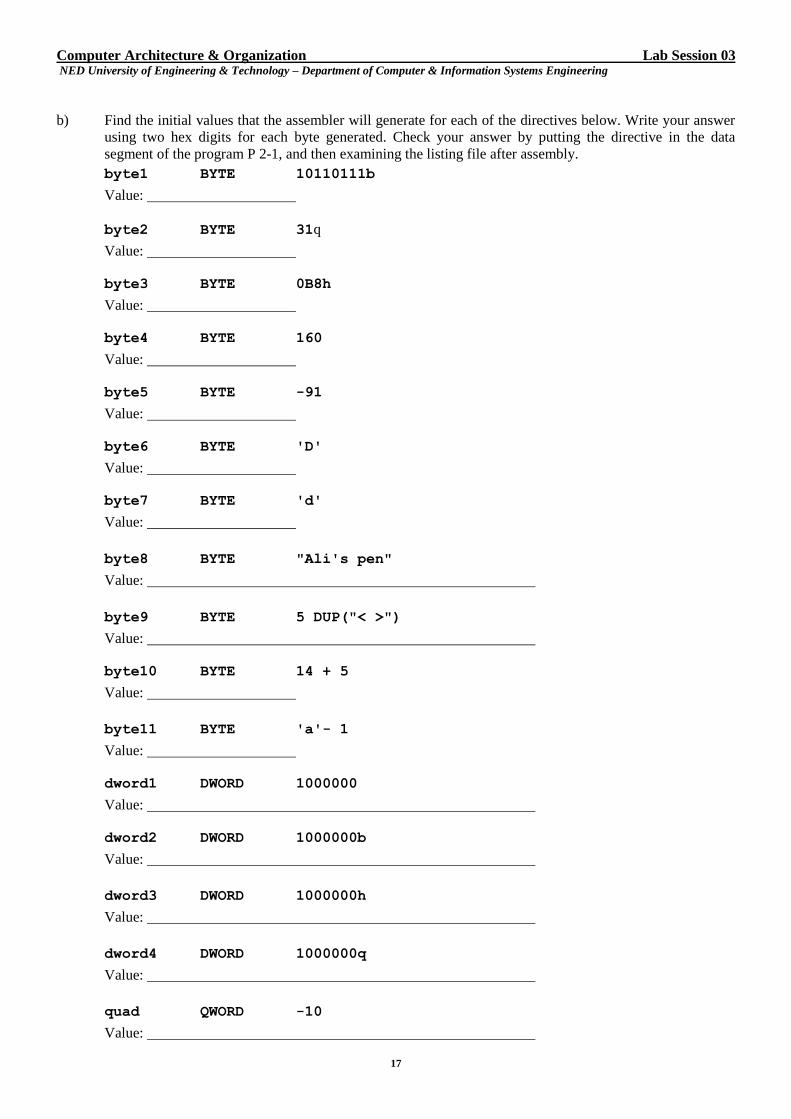
b) Find the initial values that the assembler will generate for each of the directives below. Write your answer
using two hex digits for each byte generated. Check your answer by putting the directive in the data
segment of the program P 2-1, and then examining the listing file after assembly.
byte1 BYTE 10110111b
Value:
byte2 BYTE 31q
Value:
byte3 BYTE 0B8h
Value:
byte4 BYTE 160
Value:
byte5 BYTE -91
Value:
byte6 BYTE 'D'
Value:
byte7 BYTE 'd'
Value:
byte8 BYTE "Ali's pen"
Value:
byte9 BYTE 5 DUP("< >")
Value:
byte10 BYTE 14 + 5
Value:
byte11 BYTE 'a'- 1
Value:
dword1 DWORD 1000000
Value:
dword2 DWORD 1000000b
Value:
dword3 DWORD 1000000h
Value:
dword4 DWORD 1000000q
Value:
quad QWORD -10
Value:
Computer Architecture & Organization Lab Session 03 NED University of Engineering & Technology – Department of Computer & Information Systems Engineering
18
c) Would it make any difference if the following instructions in the program P 3-1 are replaced by the single
instruction add eax, number1? Briefly explain.
mov eax, number1
add eax, number2
d) Starting with the windows32 project, modify the program P 3-1 to prompt for input and add three numbers,
and display the sum. Trace execution using the debugger.
Computer Architecture & Organization Lab Session 03 NED University of Engineering & Technology – Department of Computer & Information Systems Engineering
19
e) The instruction sub eax, number subtracts the double-word at number from the double-word in eax
register. Starting with the windows32 project, modify the program P 3-1 to prompt for and input two
numbers, subtract the second number from the first, and finally, display the result. Trace execution using
the debugger.
f) Given the data segment definitions response1 BYTE 20 DUP (? )
askLb1 BYTE "Please enter a number", 0
and the code segment macro input askLb1, response1, 20
a) What bytes will be stored in the data segment at response1if -578 is entered in the dialog box and OK is
pressed?
b) If the macro atod response1 follows the above input macro, what will be stored in the EAX register?
Computer Architecture & Organization Lab Session 04 NED University of Engineering & Technology – Department of Computer & Information Systems Engineering
20
Lab Session 04
1. OBJECT
Using x86 Data Transfer Instructions
2. THEORY
Most computer programs copy data from one location to another as is done via assignment statement in high level
languages. In 80x86 machine language, copying is done by mov ("move") instructions having the format:
mov destination, source
The value at the source location is not changed. The destination location is the same size as the source. Both source
and destinations are not allowed in memory. No mov instruction changes any 80x86 flag.
All 80x86 mov instructions are coded with the same mnemonic. It's the job of the assembler to select the correct
opcode and other bytes of object code by examining the operands.
We now present a special class of 80x86 mov instructions: instructions for transfer of bytes. The first group of
instructions in this class has an 8-bit register destination (AH, AL, BH, BL, CH, CL, DH, DL) and an immediate
source operand. Depending upon the destination register, each mov instruction in this class has a distinct opcode
which is the first byte in the object code and the second byte is the immediate source operand. Had all the mov
instructions in this group carried the same opcode, it would have required an additional byte to code the destination
register. Data transfer is the most commonly used operation in programming and hence the mov instructions are the
most frequently used instructions. It therefore makes sense that these instructions take minimum possible bytes in
the object code.
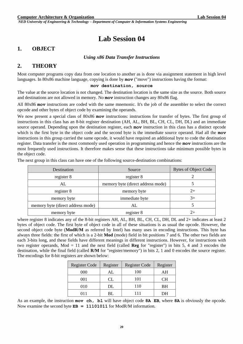
The next group in this class can have one of the following source-destination combinations:
Destination Source Bytes of Object Code
register 8 register 8 2
AL memory byte (direct address mode) 5
register 8 memory byte 2+
memory byte immediate byte 3+
memory byte (direct address mode) AL 5
memory byte register 8 2+
where register 8 indicates any of the 8-bit registers AH, AL, BH, BL, CH, CL, DH, DL and 2+ indicates at least 2
bytes of object code. The first byte of object code in all of these situations is as usual the opcode. However, the
second object code byte (ModR/M as referred by Intel) has many uses in encoding instructions. This byte has
always three fields: the first of which is a 2-bit Mod (mode) field in bit positions 7 and 6. The other two fields are
each 3-bits long, and these fields have different meanings in different instructions. However, for instructions with
two register operands, Mod = 11 and the next field (called Reg for "register") in bits 5, 4 and 3 encodes the
destination, while the final field (called R/M for "register/memory") in bits 2, 1 and 0 encodes the source register.
The encodings for 8-bit registers are shown below:
Register Code Register Register Code Register
000 AL 100 AH
001 CL 101 CH
010 DL 110 BH
011 BL 111 DH
As an example, the instruction mov ch, bl will have object code 8A EB, where 8A is obviously the opcode.
Now examine the second byte EB = 11101011 for ModR/M information.
Computer Architecture & Organization Lab Session 04 NED University of Engineering & Technology – Department of Computer & Information Systems Engineering
21
7 6 5 4 3 2 1 0
1 1 1 0 1 0 1 1
Mod =11 (two register operands) destination register = CH source register = BL
The 80x86 has a very useful xchg instruction that exchanges in one data location with data in another location. For
example, xchg eax, ebx. This instruction cannot have both operands in memory. It does not alter any flag.
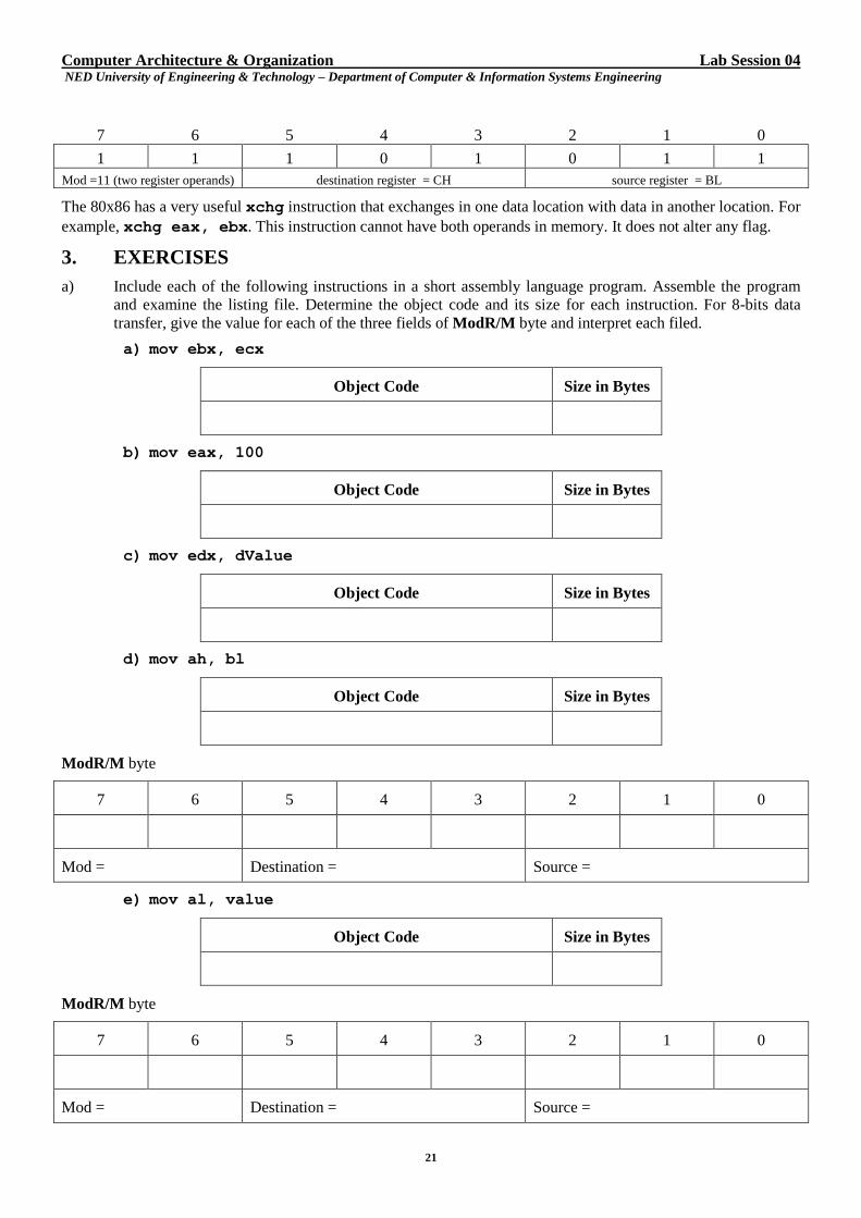
3. EXERCISES
a) Include each of the following instructions in a short assembly language program. Assemble the program
and examine the listing file. Determine the object code and its size for each instruction. For 8-bits data
transfer, give the value for each of the three fields of ModR/M byte and interpret each filed.
a) mov ebx, ecx
Object Code Size in Bytes
b) mov eax, 100
Object Code Size in Bytes
c) mov edx, dValue
Object Code Size in Bytes
d) mov ah, bl
Object Code Size in Bytes
ModR/M byte
7 6 5 4 3 2 1 0
Mod = Destination = Source =
e) mov al, value
Object Code Size in Bytes
ModR/M byte
7 6 5 4 3 2 1 0
Mod = Destination = Source =
Computer Architecture & Organization Lab Session 04 NED University of Engineering & Technology – Department of Computer & Information Systems Engineering
22
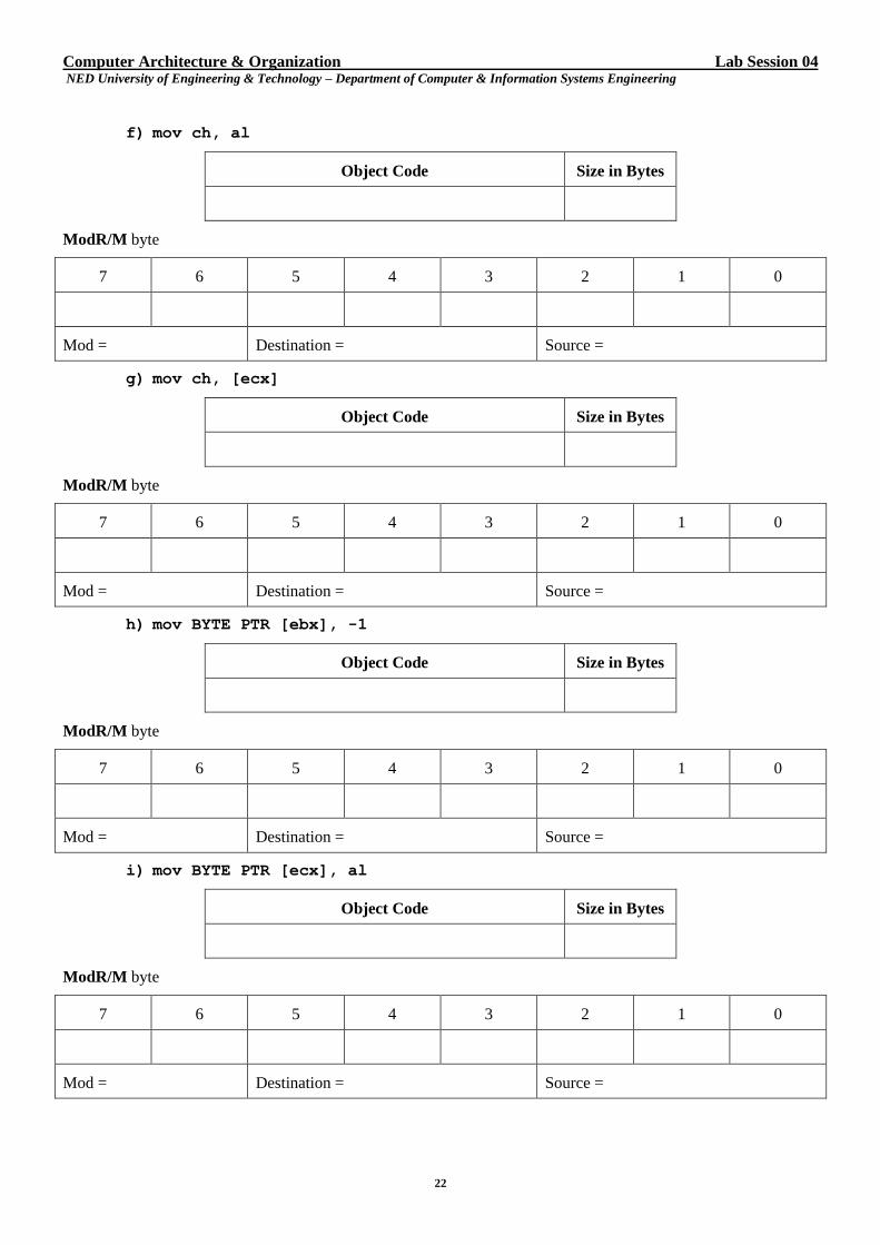
f) mov ch, al
Object Code Size in Bytes
ModR/M byte
7 6 5 4 3 2 1 0
Mod = Destination = Source =
g) mov ch, [ecx]
Object Code Size in Bytes
ModR/M byte
7 6 5 4 3 2 1 0
Mod = Destination = Source =
h) mov BYTE PTR [ebx], -1
Object Code Size in Bytes
ModR/M byte
7 6 5 4 3 2 1 0
Mod = Destination = Source =
i) mov BYTE PTR [ecx], al
Object Code Size in Bytes
ModR/M byte
7 6 5 4 3 2 1 0
Mod = Destination = Source =
Computer Architecture & Organization Lab Session 04 NED University of Engineering & Technology – Department of Computer & Information Systems Engineering
23
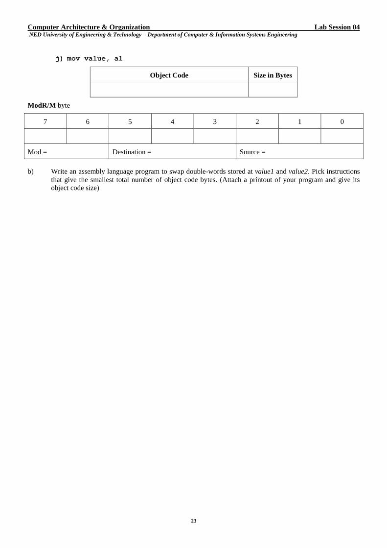
j) mov value, al
Object Code Size in Bytes
ModR/M byte
7 6 5 4 3 2 1 0
Mod = Destination = Source =
b) Write an assembly language program to swap double-words stored at value1 and value2. Pick instructions
that give the smallest total number of object code bytes. (Attach a printout of your program and give its
object code size)
Computer Architecture & Organization Lab Session 05 NED University of Engineering & Technology – Department of Computer & Information Systems Engineering
24
Lab Session 05
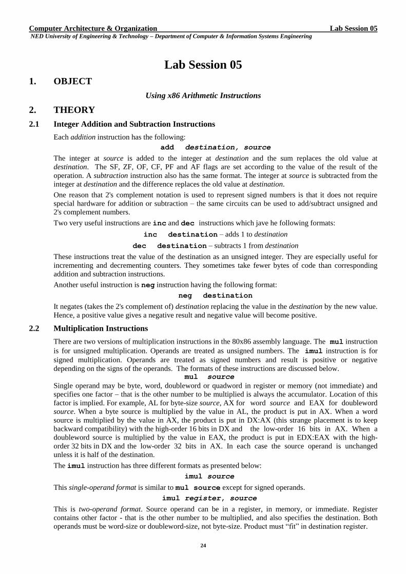
1. OBJECT
Using x86 Arithmetic Instructions
2. THEORY
2.1 Integer Addition and Subtraction Instructions
Each addition instruction has the following:
add destination, source
The integer at source is added to the integer at destination and the sum replaces the old value at
destination. The SF, ZF, OF, CF, PF and AF flags are set according to the value of the result of the
operation. A subtraction instruction also has the same format. The integer at source is subtracted from the
integer at destination and the difference replaces the old value at destination.
One reason that 2's complement notation is used to represent signed numbers is that it does not require
special hardware for addition or subtraction – the same circuits can be used to add/subtract unsigned and
2's complement numbers.
Two very useful instructions are inc and dec instructions which jave he following formats:
inc destination – adds 1 to destination
dec destination – subtracts 1 from destination
These instructions treat the value of the destination as an unsigned integer. They are especially useful for
incrementing and decrementing counters. They sometimes take fewer bytes of code than corresponding
addition and subtraction instructions.
Another useful instruction is neg instruction having the following format:
neg destination
It negates (takes the 2's complement of) destination replacing the value in the destination by the new value.
Hence, a positive value gives a negative result and negative value will become positive.
2.2 Multiplication Instructions
There are two versions of multiplication instructions in the 80x86 assembly language. The mul instruction
is for unsigned multiplication. Operands are treated as unsigned numbers. The imul instruction is for
signed multiplication. Operands are treated as signed numbers and result is positive or negative
depending on the signs of the operands. The formats of these instructions are discussed below. mul source
Single operand may be byte, word, doubleword or quadword in register or memory (not immediate) and
specifies one factor – that is the other number to be multiplied is always the accumulator. Location of this
factor is implied. For example, AL for byte-size source, AX for word source and EAX for doubleword
source. When a byte source is multiplied by the value in AL, the product is put in AX. When a word
source is multiplied by the value in AX, the product is put in DX:AX (this strange placement is to keep
backward compatibility) with the high-order 16 bits in DX and the low-order 16 bits in AX. When a
doubleword source is multiplied by the value in EAX, the product is put in EDX:EAX with the high-
order 32 bits in DX and the low-order 32 bits in AX. In each case the source operand is unchanged
unless it is half of the destination.
The imul instruction has three different formats as presented below:
imul source
This single-operand format is similar to mul source except for signed operands.
imul register, source
This is two-operand format. Source operand can be in a register, in memory, or immediate. Register
contains other factor - that is the other number to be multiplied, and also specifies the destination. Both
operands must be word-size or doubleword-size, not byte-size. Product must “fit” in destination register.
Computer Architecture & Organization Lab Session 05 NED University of Engineering & Technology – Department of Computer & Information Systems Engineering
25
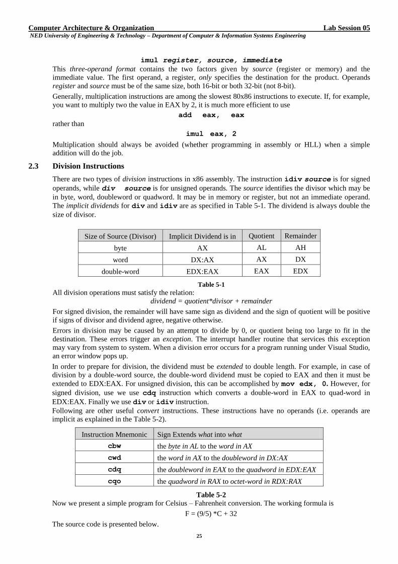
imul register, source, immediate
This three-operand format contains the two factors given by source (register or memory) and the
immediate value. The first operand, a register, only specifies the destination for the product. Operands
register and source must be of the same size, both 16-bit or both 32-bit (not 8-bit).
Generally, multiplication instructions are among the slowest 80x86 instructions to execute. If, for example,
you want to multiply two the value in EAX by 2, it is much more efficient to use
add eax, eax
rather than
imul eax, 2
Multiplication should always be avoided (whether programming in assembly or HLL) when a simple
addition will do the job.
2.3 Division Instructions
There are two types of division instructions in x86 assembly. The instruction idiv source is for signed
operands, while div source is for unsigned operands. The source identifies the divisor which may be
in byte, word, doubleword or quadword. It may be in memory or register, but not an immediate operand.
The implicit dividends for div and idiv are as specified in Table 5-1. The dividend is always double the
size of divisor.
Size of Source (Divisor) Implicit Dividend is in Quotient Remainder
byte AX AL AH
word DX:AX AX DX
double-word EDX:EAX EAX EDX
Table 5-1
All division operations must satisfy the relation:
dividend = quotient*divisor + remainder
For signed division, the remainder will have same sign as dividend and the sign of quotient will be positive
if signs of divisor and dividend agree, negative otherwise.
Errors in division may be caused by an attempt to divide by 0, or quotient being too large to fit in the
destination. These errors trigger an exception. The interrupt handler routine that services this exception
may vary from system to system. When a division error occurs for a program running under Visual Studio,
an error window pops up.
In order to prepare for division, the dividend must be extended to double length. For example, in case of
division by a double-word source, the double-word dividend must be copied to EAX and then it must be
extended to EDX:EAX. For unsigned division, this can be accomplished by mov edx, 0. However, for
signed division, use we use cdq instruction which converts a double-word in EAX to quad-word in
EDX:EAX. Finally we use div or idiv instruction.
Following are other useful convert instructions. These instructions have no operands (i.e. operands are
implicit as explained in the Table 5-2).
Instruction Mnemonic Sign Extends what into what
cbw the byte in AL to the word in AX
cwd the word in AX to the doubleword in DX:AX
cdq the doubleword in EAX to the quadword in EDX:EAX
cqo the quadword in RAX to octet-word in RDX:RAX
Table 5-2
Now we present a simple program for Celsius – Fahrenheit conversion. The working formula is
F = (9/5) *C + 32
The source code is presented below.
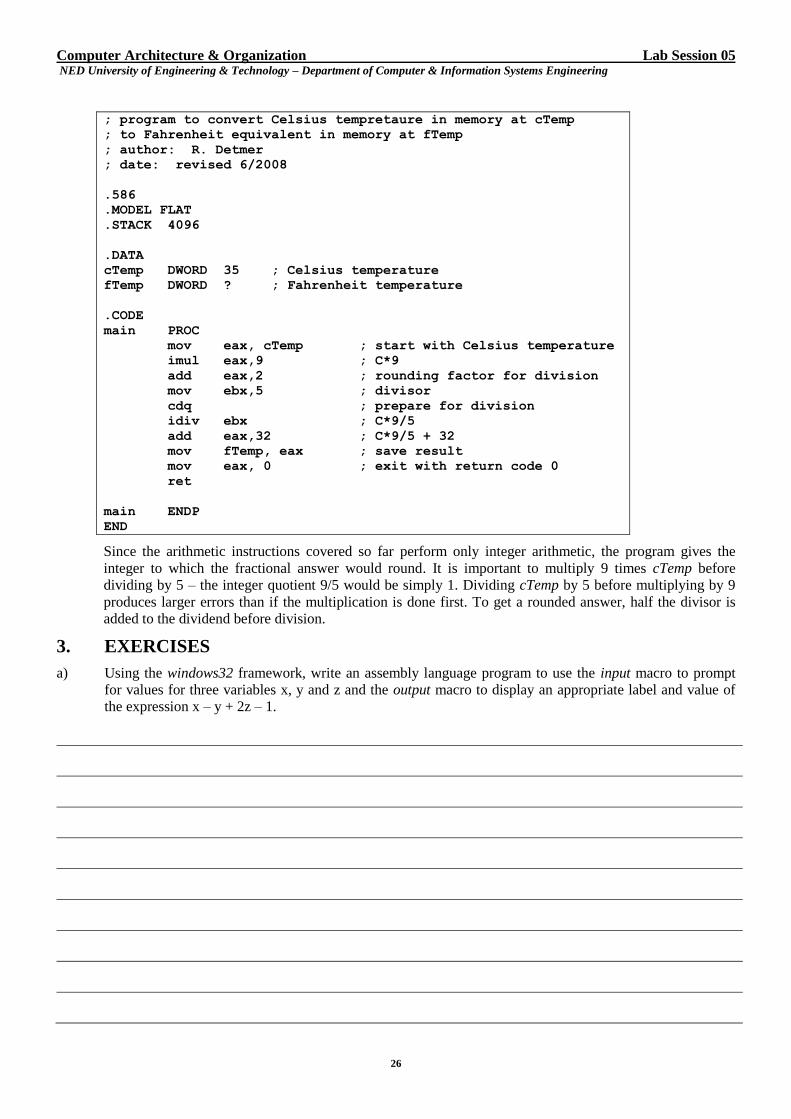
Computer Architecture & Organization Lab Session 05 NED University of Engineering & Technology – Department of Computer & Information Systems Engineering
26
; program to convert Celsius tempretaure in memory at cTemp
; to Fahrenheit equivalent in memory at fTemp
; author: R. Detmer
; date: revised 6/2008
.586
.MODEL FLAT
.STACK 4096
.DATA
cTemp DWORD 35 ; Celsius temperature
fTemp DWORD ? ; Fahrenheit temperature
.CODE
main PROC
mov eax, cTemp ; start with Celsius temperature
imul eax,9 ; C*9
add eax,2 ; rounding factor for division
mov ebx,5 ; divisor
cdq ; prepare for division
idiv ebx ; C*9/5
add eax,32 ; C*9/5 + 32
mov fTemp, eax ; save result
mov eax, 0 ; exit with return code 0
ret
main ENDP
END
Since the arithmetic instructions covered so far perform only integer arithmetic, the program gives the
integer to which the fractional answer would round. It is important to multiply 9 times cTemp before
dividing by 5 – the integer quotient 9/5 would be simply 1. Dividing cTemp by 5 before multiplying by 9
produces larger errors than if the multiplication is done first. To get a rounded answer, half the divisor is
added to the dividend before division.
3. EXERCISES
a) Using the windows32 framework, write an assembly language program to use the input macro to prompt
for values for three variables x, y and z and the output macro to display an appropriate label and value of
the expression x – y + 2z – 1.
Computer Architecture & Organization Lab Session 05 NED University of Engineering & Technology – Department of Computer & Information Systems Engineering
27
b) Using the console32 framework, write an assembly language program, that computes in EAX the value of
the expression x – 2y + 4z for double-words in memory at x, y, and z. Choose the current month (1 – 12),
day (1 – 31), and year (all four digits) for the values of x, y, and z respectively. Execute your program
under the control of debugger.
Computer Architecture & Organization Lab Session 05 NED University of Engineering & Technology – Department of Computer & Information Systems Engineering
28
c) Using the windows32 framework, modify the program in exercise (b) to use the input macro to prompt
for values for three variables x, y and z and the output macro to display an appropriate label and value of
the expression x – 2y + 4z
d) Using the windows32 framework, write an assembly language program that prompts for and inputs the
length, width, and height of a box and calculates and displays its surface area.
surface area = 2 * (length * width + length * height + width * height)
[Caution: Remember length and width are assembler-reserved words]
Computer Architecture & Organization Lab Session 05 NED University of Engineering & Technology – Department of Computer & Information Systems Engineering
29
e) Using the windows32 framework, write an assembly language program that prompts for and inputs four grades
grade1, grdae2, grade3, and grade4. Suppose that the last grade is a final exam grade that counts twice as
much as the other three. Calculate the sum (adding the last grade twice) and the average (sum/5). Display the
sum and average on two lines of a message box, each line with an appropriate label.
Computer Architecture & Organization Lab Session 05 NED University of Engineering & Technology – Department of Computer & Information Systems Engineering
30
Computer Architecture & Organization Lab Session 06 NED University of Engineering & Technology – Department of Computer & Information Systems Engineering
31
Lab Session 06
1. OBJECT
Implementing Branching in x86 Assembly Language
2. THEORY
Computers derive much of their power from their ability to selectively execute code and from the speed at which
they execute repetitive algorithms. Programs in HLL such as Java or C++ use if-then, if-then-else, and case
structures to selectively execute code and loop structures such as while (pre-test) loops, until (post-test) loops, and
for (counter-controlled) loops to repetitively execute code. Some HLLs have a goto for unconditional branching.
Somewhat more primitive languages like older versions of FORTRAN or BASIC, depend on fairly simple if
statements and abundance of goto statements for both selective execution and looping.
The 80x86 assembly language programmer's job is similar to the old FORTRAN or BASIC programmer's job. The
80x86 processor can execute some instructions that are roughly comparable to for statements, but most branching
and looping is done with 80x86 statements that are similar to, but even more primitive than, simple if and goto
statements.
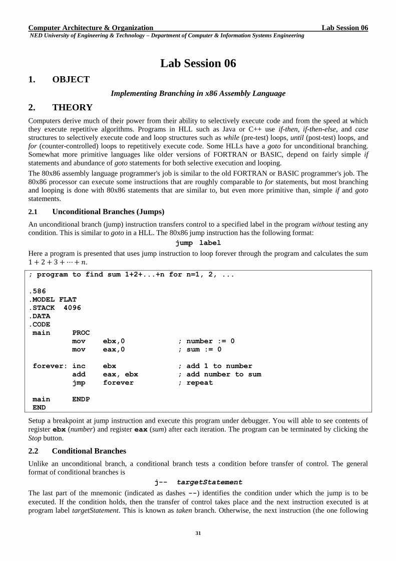
2.1 Unconditional Branches (Jumps)
An unconditional branch (jump) instruction transfers control to a specified label in the program without testing any
condition. This is similar to goto in a HLL. The 80x86 jump instruction has the following format:
jump label
Here a program is presented that uses jump instruction to loop forever through the program and calculates the sum
.
; program to find sum 1+2+...+n for n=1, 2, ...
.586
.MODEL FLAT
.STACK 4096
.DATA
.CODE
main PROC
mov ebx,0 ; number := 0
mov eax,0 ; sum := 0
forever: inc ebx ; add 1 to number
add eax, ebx ; add number to sum
jmp forever ; repeat
main ENDP
END
Setup a breakpoint at jump instruction and execute this program under debugger. You will able to see contents of
register ebx (number) and register eax (sum) after each iteration. The program can be terminated by clicking the
Stop button.
2.2 Conditional Branches
Unlike an unconditional branch, a conditional branch tests a condition before transfer of control. The general
format of conditional branches is
j-- targetStatement
The last part of the mnemonic (indicated as dashes --) identifies the condition under which the jump is to be
executed. If the condition holds, then the transfer of control takes place and the next instruction executed is at
program label targetStatement. This is known as taken branch. Otherwise, the next instruction (the one following
Computer Architecture & Organization Lab Session 06 NED University of Engineering & Technology – Department of Computer & Information Systems Engineering
32
the conditional branch) is executed in which it is known as not taken branch. This conditional branching is used to
implement if structures, other selection structures, and loop structures in 80x86 assembly language.
Most conditions considered by the conditional jump instructions are settings of flags in the EFLAGS register. For
example, jz endWhile means to transfer control to the instruction with label endWhile, if the zero flag ZF is set
to 1. Conditional branch instructions don not modify flags; they just react to previously set flag values.
Most common way to set flags for conditional branches is to use compare instruction that has the following format:
cmp operand1, operand2
Flags are set the same as for the subtraction operation operand1 – operand2. Operands, however, are not
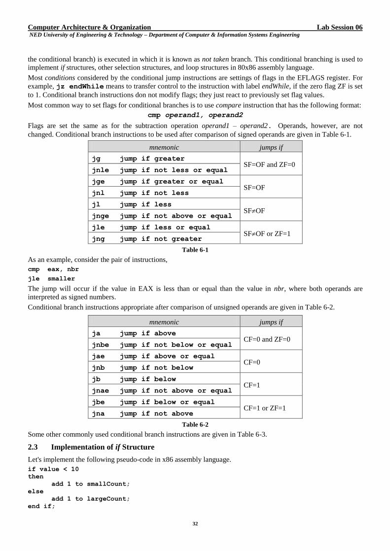
changed. Conditional branch instructions to be used after comparison of signed operands are given in Table 6-1.
mnemonic jumps if
jg jump if greater SF=OF and ZF=0
jnle jump if not less or equal
jge jump if greater or equal SF=OF
jnl jump if not less
jl jump if less SFOF
jnge jump if not above or equal
jle jump if less or equal SFOF or ZF=1
jng jump if not greater
Table 6-1
As an example, consider the pair of instructions,
cmp eax, nbr
jle smaller
The jump will occur if the value in EAX is less than or equal than the value in nbr, where both operands are
interpreted as signed numbers.
Conditional branch instructions appropriate after comparison of unsigned operands are given in Table 6-2.
mnemonic jumps if
ja jump if above CF=0 and ZF=0
jnbe jump if not below or equal
jae jump if above or equal CF=0
jnb jump if not below
jb jump if below CF=1
jnae jump if not above or equal
jbe jump if below or equal CF=1 or ZF=1
jna jump if not above
Table 6-2
Some other commonly used conditional branch instructions are given in Table 6-3.
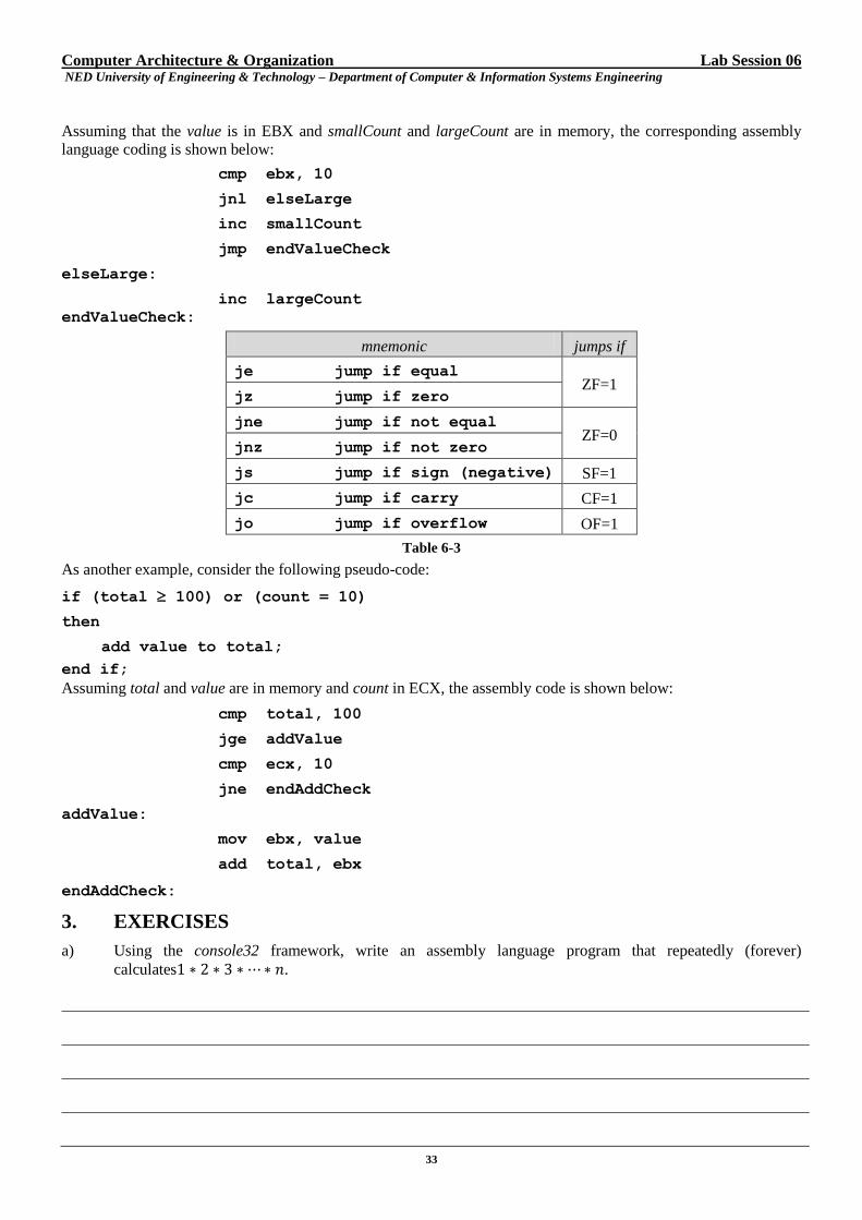
2.3 Implementation of if Structure
Let's implement the following pseudo-code in x86 assembly language.
if value < 10
then
add 1 to smallCount;
else
add 1 to largeCount;
end if;
Computer Architecture & Organization Lab Session 06 NED University of Engineering & Technology – Department of Computer & Information Systems Engineering
33
Assuming that the value is in EBX and smallCount and largeCount are in memory, the corresponding assembly
language coding is shown below:
cmp ebx, 10
jnl elseLarge
inc smallCount
jmp endValueCheck
elseLarge:
inc largeCount
endValueCheck:
mnemonic jumps if
je jump if equal ZF=1
jz jump if zero
jne jump if not equal ZF=0
jnz jump if not zero
js jump if sign (negative) SF=1
jc jump if carry CF=1
jo jump if overflow OF=1
Table 6-3
As another example, consider the following pseudo-code:
if (total 100) or (count = 10)
then
add value to total;
end if;
Assuming total and value are in memory and count in ECX, the assembly code is shown below:
cmp total, 100
jge addValue
cmp ecx, 10
jne endAddCheck
addValue:
mov ebx, value
add total, ebx
endAddCheck:
3. EXERCISES
a) Using the console32 framework, write an assembly language program that repeatedly (forever)
calculates .
Computer Architecture & Organization Lab Session 06 NED University of Engineering & Technology – Department of Computer & Information Systems Engineering
34
b) Using the windows32 framework, write an assembly language program that will repeatedly prompt for a
number using a dialog box. After each number is entered, display the sum and average of all the numbers
entered so far using separate message boxes for the sum and the average. (You can terminate the program
by clicking the Stop button when the dialog box is waiting for a number)
c) Assume for each part of this exercise that the EAX contains 00 00 00 4F and the doubleword referenced by
value contains FF FF FF 38. Determine whether each of the following conditional branch instructions causes
a transfer of control to label dest.
i. cmp eax, value
jl dest

Computer Architecture & Organization Lab Session 06 NED University of Engineering & Technology – Department of Computer & Information Systems Engineering
35
Your answer: YES NO
Reason
ii. cmp eax, value
jb dest
Your answer: YES NO
Reason
iii. cmp eax, 04fh
je dest
Your answer: YES NO
Reason
iv. add eax, 200
js dest
Your answer: YES NO
Reason
Computer Architecture & Organization Lab Session 06 NED University of Engineering & Technology – Department of Computer & Information Systems Engineering
36
v. add value, 200
jz dest
Your answer: YES NO
Reason
d) Each part of this exercise gives a design with an if structure and some assumptions about how the variables
are stored. Give a fragment of assembly language code that implements the design.
i. if count = 0
then
count := value;
end if;
Assumptions: count is in ECX; value references a doubleword in memory
ii. if count > value
then
count := 0;
end if;
Assumptions: count is in ECX; value references a doubleword in memory
Computer Architecture & Organization Lab Session 06 NED University of Engineering & Technology – Department of Computer & Information Systems Engineering
37
iii. if (value < -1000) or (value > 1000)
then
value := 0;
end if;
Assumptions: value is in EDX; value references a doubleword in memory
Computer Architecture & Organization Lab Session 07 NED University of Engineering & Technology – Department of Computer & Information Systems Engineering
38
Lab Session 07
1. OBJECT
Implementation of Loop Structures in x86 Assembly Language
2. THEORY
Looping (repeated execution of a program fragment) is the fundamental capability that gives programming languages and
computers the real power. Commonly used loop structures include while, until, and for loops. This lab describes, in detail,
implementation of all of these three structures in 80x86 assembly language.
2.1 Implementation of while Loop
A while loop can be indicated by the following pseudocode design:
while continuation condition loop
... { body of loop }
end while;
A while loop is a pre-test loop – the continuation condition, a Boolean expression, is checked before the loop body
is executed. Whenever it is true the loop body is executed and then the continuation condition is checked again.
When it is false execution continues with the statement following the loop. It may take several 80x86 instructions
to evaluate and check a continuation condition.
An 80x86 implementation of a while loop follows a pattern much like this one:
while1: . ; code to check Boolean expression
.
.
body: . ; loop body
.
.
jmp while1 ; go check condition again
endWhile1:
As an example, consider the following pseudocode:
while (sum < 1000) loop
add count to sum;
add 1 to count;
end while;
Assuming sum in memory and count in ECX, the corresponding assembly code follows:
whileSum: cmp sum, 1000
jnl endWhileSum
add sum, ecx
inc ecx
jmp whileSum endWhileSum:
Consider another example. Suppose that the integer base 2 logarithm of a positive integer number needs to be
determined. The integer base 2 logarithm of a positive integer is the largest integer x such that < number. The
following pseudocode will do the job:
x := 0;
twoTox :=1;
while twoTox < number loop
Computer Architecture & Organization Lab Session 07 NED University of Engineering & Technology – Department of Computer & Information Systems Engineering
39
multiply twoTox by 2;
add 1 to x;
end while;
subtract 1 from x;
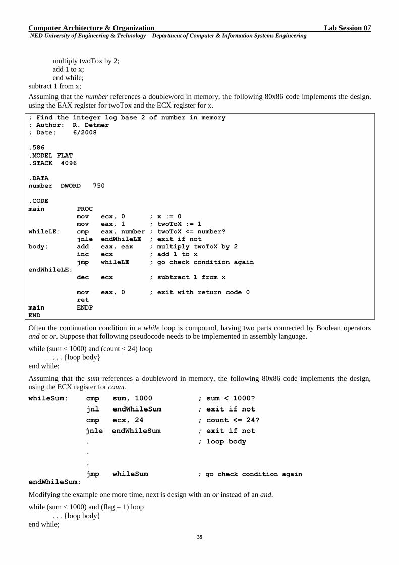
Assuming that the number references a doubleword in memory, the following 80x86 code implements the design,
using the EAX register for twoTox and the ECX register for x.
; Find the integer log base 2 of number in memory
; Author: R. Detmer
; Date: 6/2008
.586
.MODEL FLAT
.STACK 4096
.DATA
number DWORD 750
.CODE
main PROC
mov ecx, 0 ; x := 0
mov eax, 1 ; twoToX := 1
whileLE: cmp eax, number ; twoToX <= number?
jnle endWhileLE ; exit if not
body: add eax, eax ; multiply twoToX by 2
inc ecx ; add 1 to x
jmp whileLE ; go check condition again
endWhileLE:
dec ecx ; subtract 1 from x
mov eax, 0 ; exit with return code 0
ret
main ENDP
END
Often the continuation condition in a while loop is compound, having two parts connected by Boolean operators
and or or. Suppose that following pseudocode needs to be implemented in assembly language.
while (sum < 1000) and (count < 24) loop
. . . {loop body}
end while;
Assuming that the sum references a doubleword in memory, the following 80x86 code implements the design,
using the ECX register for count.
whileSum: cmp sum, 1000 ; sum < 1000?
jnl endWhileSum ; exit if not
cmp ecx, 24 ; count <= 24?
jnle endWhileSum ; exit if not
. ; loop body
.
.
jmp whileSum ; go check condition again endWhileSum:
Modifying the example one more time, next is design with an or instead of an and.
while (sum < 1000) and (flag = 1) loop
. . . {loop body}
end while;
Computer Architecture & Organization Lab Session 07 NED University of Engineering & Technology – Department of Computer & Information Systems Engineering
40
This time assume that the sum is in EAX register, and that flag is a single byte in BL register. The following 80x86
code implements the design.
whileSum: cmp eax, 1000 ; sum < 1000?
jl body ; execute body if so
cmp bl, 1 ; flag = 1?
jne endWhileSum ; exit if not
body: . ; loop body
.
.
jmp whileSum ; go check condition again endWhileSum:
2.2 Implementation of for Loop
The for loop is a counter-controlled loop that executes once for each value of a loop index (also known as loop
counter) in a given range. Often the number of times the body of a loop must be executed is known in advance,
either as a constant that can be coded when a program is written, or as the value of a variable that is assigned before
the loop is executed. The for loop is ideal for coding such a loop. A for loop can be described by the following
pseudocode:
for index := initialValue to finalValue loop
... { body of loop }
end for;
A for loop can be easily converted to a while loop as follows:
index := initialValue;
while index ≤ finalValue loop
... { body of loop }
add 1 to index;
end while;
This technique always works and is often the best way to implement a for loop. However, the 80x86 processor has
instructions that make coding certain for loops quite easy. The loop instruction is designed to implement
“backward” counter-controlled loops:
for index := count downto 1 loop
... { body of loop }
end for;
The loop instruction has the following format:
loop statementLabel
where statementLabel is the label of a statement which is a short displacement (128 bytes backward or 127 bytes
forward) from the loop instruction. The execution proceeds as under:
The value in ECX is decremented. If the new value in ECX is zero, then execution continues with the statement
following the loop instruction. If the new value in ECX is non-zero, then a jump to the instruction at
statementLabel takes place.
Although, ECX is a general-purpose register, it has a special role as a counter in the loop instruction and in several
other 80x86 instructions. No other register can be substituted for ECX in these instructions. In practice, this often
means that when a loop instruction is coded, ECX is not used for other purposes.
Consider the following pseudocode:
sum := 0
for count := 20 downto 1 loop
add count to sum;
end for;
Computer Architecture & Organization Lab Session 07 NED University of Engineering & Technology – Department of Computer & Information Systems Engineering
41
Assuming sum in EAX and count in ECX, the corresponding assembly code follows:
mov eax, 0
mov ecx, 20
forCount: add eax, ecx
loop forCount
Now suppose that the doubleword in memory referenced by number contains the number of times a loop body must
be executed. The 80x86 implementation follows:
mov ecx, number ; number of iterations
forIndex: . ; loop body
.
.
loop forIndex ; repeat body number times
If ECX is initially 0, then 00000000 will be decremented to FFFFFFFF, then FFFFFFFE, etc., for a total of
4,294,967,296 iterations. The jecxz (“jump if ECX is zero”) instruction can be used to guard a loop implemented
with the loop instruction. Using the jecxz instruction, the previous example can be coded as follows:
mov ecx, number ; number of iterations
jecxz endFor ; skip loop if number = 0
forIndex: . ; loop body
.
.
loop forIndex ; repeat body number times
The jecxz instruction can also be used to code a backward for loop when the loop body is longer than 127 bytes,
too large for a loop instruction's single byte address. For example, the structure
for counter := 50 downto 1 loop
... { loop body }
end for;
could be coded as follows:
mov ecx, 50 ; number of iterations
forCounter: . ; loop body
.
.
dec ecx ; decrement loop counter
jecxz endFor ; exit if counter = 0
jmp forCounter ; otherwise repeat body
endFor:
It is often convenient to use to use loop instruction even when the loop index increases and must be used within
the body of the loop. As an example, consider the following code:
for index := 1 to 50 loop
... { loop body using index }
end for;
Here a register, say for example, EBX can be used to store index counting from 1 to 50, while the ECX register
counts down from 50 to 1.
The corresponding assembly code is as follows:
mov ebx, 1 ; index := 1
mov ecx, 50 ; number of iterations
forNbr: . ;
Computer Architecture & Organization Lab Session 07 NED University of Engineering & Technology – Department of Computer & Information Systems Engineering
42
. ; use value in EBX for index
.
inc ebx ; add 1 to index
loop forNbr ; repeat
2.3 Implementation of until Loop
An until loop is a post-test loop – the condition is checked after the body of loop is executed. In general, an until
loop can be represented as follows:
repeat ... { body of loop } until termination condition;
Termination condition is checked after the loop body is executed. If it is true, execution continues with the
statement following the until loop. Otherwise, the loop body is executed again. Thus, loop body is executed at least
once. An 80x86 implementation of an until loop follows:
until: . ; start of loop body
.
.
body: . ; code to check termination condition
enduntil:
Consider the following pseudocode:
repeat add 2*count to sum; add 1 to count; until (sum > 1000);
Assuming that the sum references a doubleword in memory, the following 80x86 code implements the pseudocode,
using the ECX register for count.
repeatLoop: add sum, ecx
add sum, ecx
inc ecx
cmp sum, 1000
jng repeatLoop
endUntilLoop:
3. EXERCISES
a) Using the windows32 framework, write an assembly language program that will use a dialog box to
prompt for an integer n, compute the sum of the integers from 1 to n and use a dialog box to display the
sum.
Computer Architecture & Organization Lab Session 07 NED University of Engineering & Technology – Department of Computer & Information Systems Engineering
43
b) Using the console32 framework, write an assembly language program that will find the smallest integer n
for which is at least 1000.
Computer Architecture & Organization Lab Session 07 NED University of Engineering & Technology – Department of Computer & Information Systems Engineering
44
c) Using the windows32 framework, write an assembly language program that will use a dialog box to prompt
for an integer n, compute the sum of the squares of all integers from 1 to n and use a dialog box to display
the sum.
d) The following algorithm will find the greatest common divisor (GCD) of number1 and number2.
gcd := number1; remainder := number2; repeat dividend := gcd; gcd := remainder; remainder := dividend mod gcd; until (remainder = 0);
Using the windows32 framework, write an assembly language program that uses dialog boxes to prompt
for and input values for number1 and number2 and uses a message box to display the GCD.
Computer Architecture & Organization Lab Session 07 NED University of Engineering & Technology – Department of Computer & Information Systems Engineering
45
Computer Architecture & Organization Lab Session 07 NED University of Engineering & Technology – Department of Computer & Information Systems Engineering
46
e) The binomial coefficient ( ) is defined for integers 0 < k < n by
( ) =
( )
Assuming that values for n and k are stored in doublewords in memory, use the windows32 framework,
write an assembly language program that will use a dialog boxe to prompt for and input n and k, compute
( ) using the above formula and use a message box to display the binomial coefficient. (Hint: Do not
calculate n! and k! separately. Instead, calculate
as ( ) ( )

Computer Architecture & Organization Lab Session 07 NED University of Engineering & Technology – Department of Computer & Information Systems Engineering
47
Computer Architecture & Organization Lab Session 08 NED University of Engineering & Technology – Department of Computer & Information Systems Engineering
48
Lab Session 08
1. OBJECT
Array Processing in x86 Assembly Language
2. THEORY
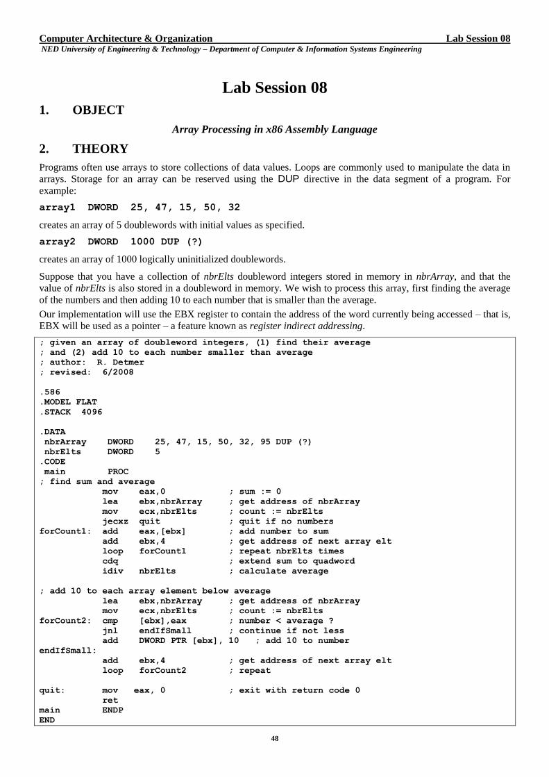
Programs often use arrays to store collections of data values. Loops are commonly used to manipulate the data in
arrays. Storage for an array can be reserved using the DUP directive in the data segment of a program. For
example:
array1 DWORD 25, 47, 15, 50, 32
creates an array of 5 doublewords with initial values as specified.
array2 DWORD 1000 DUP (?)
creates an array of 1000 logically uninitialized doublewords.
Suppose that you have a collection of nbrElts doubleword integers stored in memory in nbrArray, and that the
value of nbrElts is also stored in a doubleword in memory. We wish to process this array, first finding the average
of the numbers and then adding 10 to each number that is smaller than the average.
Our implementation will use the EBX register to contain the address of the word currently being accessed – that is,
EBX will be used as a pointer – a feature known as register indirect addressing.
; given an array of doubleword integers, (1) find their average
; and (2) add 10 to each number smaller than average
; author: R. Detmer
; revised: 6/2008
.586
.MODEL FLAT
.STACK 4096
.DATA
nbrArray DWORD 25, 47, 15, 50, 32, 95 DUP (?)
nbrElts DWORD 5
.CODE
main PROC
; find sum and average
mov eax,0 ; sum := 0
lea ebx,nbrArray ; get address of nbrArray
mov ecx,nbrElts ; count := nbrElts
jecxz quit ; quit if no numbers
forCount1: add eax,[ebx] ; add number to sum
add ebx,4 ; get address of next array elt
loop forCount1 ; repeat nbrElts times
cdq ; extend sum to quadword
idiv nbrElts ; calculate average
; add 10 to each array element below average
lea ebx,nbrArray ; get address of nbrArray
mov ecx,nbrElts ; count := nbrElts
forCount2: cmp [ebx],eax ; number < average ?
jnl endIfSmall ; continue if not less
add DWORD PTR [ebx], 10 ; add 10 to number
endIfSmall:
add ebx,4 ; get address of next array elt
loop forCount2 ; repeat
quit: mov eax, 0 ; exit with return code 0
ret
main ENDP
END
Computer Architecture & Organization Lab Session 08 NED University of Engineering & Technology – Department of Computer & Information Systems Engineering
49
The instruction lea (load effective address) is used to load the address of a particular item in memory in a
specified register. It has the format:
lea destination, source
The destination is usually a 32-bit general register; the source is any reference to memory. The address of the
source is loaded into the register. Contrast this with the instruction mov destination, source where the
value at the source address is copied to the destination.
There are two methods of traversing an array: sequential and random. The code presented above is an example of
sequential processing of array. Now an example of random array processing is presented. This uses indexed
addressing. The address format nbrArray[4*ecx] is assembled into an address with a displacement that is the
address of nbrArray, ECX with an index register and 4 as a scaling factor for the index. When executed, the
operand used is at the address that is at the sum of the displacement and four times the contents of the of the index
register. In other words, the first operand is at nbrArray+0, the second at nbrArray+4, and so on. The advantage of
using indexed addressing is that array elements do not have to be accessed in sequential order.
As an example, consider adding 50 doublewords in an array using random access.
nbrArr DWORD 50 DUP (?)
...
mov eax, 0 ; sum := 0
mov ecx, 50 ; number of elements
mov esi, 0 ; array index
addElt: add eax, nbrArr[4*esi] ; add element
inc esi ; increment array index
loop addElt ; repeat
3. EXERCISES
a) The following pseudocode will input numbers into an array or doublewords, using the sentinel value –
9999 to terminate input.
nbrElts := 0; get address of array; prompt for and input number; while number ≠ -9999 loop add 1 to nbrElts; store number at address; add 4 to address; prompt for and input number; end while;
Use the windows32 framework, write an assembly language program that will uses a dialog box to
prompt for and input each number. Assume that no more than 100 numbers will be entered. Use a single
message box to report the sum of the numbers, how many numbers were entered (not counting the sentinel
value of course), the average of the numbers, and the count of array entries that are greater than or equal to
the average value.
Computer Architecture & Organization Lab Session 08 NED University of Engineering & Technology – Department of Computer & Information Systems Engineering
50
Computer Architecture & Organization Lab Session 08 NED University of Engineering & Technology – Department of Computer & Information Systems Engineering
51
b) Using the window32 framework, write an assembly language program that uses a dialog box to input a
string of characters into charStr, recalling that the macro input terminates a string with a NULL byte (00).
Process this string as an array of characters, replacing each uppercase letter in charStr by its lowercase
equivalent, leaving every other character changed. Use a message box to display the notified string.
Computer Architecture & Organization Lab Session 08 NED University of Engineering & Technology – Department of Computer & Information Systems Engineering
52
c) Here is a pseudo code to find the first 100 prime numbers. Using the console32 framework, write an
assembly language program that stores the primes in an array of doublewords primeArray, and examine the
contents of the primeArray using the debugger.
prime[1] :=2; {first prime number} prime[2] :=3; {second prime number} primeCount :=2; candidate := 5 {first candidate for a new prime number} while primeCount < 100 loop index := 1; while (index < primeCount) and (prime[index] does not evenly divide candidate) loop add 1 to index; end while; if (index > primeCount) then {no existing prime evenly divides the candidate, so it is new prime} add 1 to primeCount; prime[primeCount] := candidate; end if; add 2 to candidate; end while;

Computer Architecture & Organization Lab Session 08 NED University of Engineering & Technology – Department of Computer & Information Systems Engineering
53

Computer Architecture & Organization Lab Session 08 NED University of Engineering & Technology – Department of Computer & Information Systems Engineering
54
d) Using the windows32 framework, write an assembly language program that inputs a collection of integers
into an array and implements sequential search for a particular integer entered by the user.
Computer Architecture & Organization Lab Session 08 NED University of Engineering & Technology – Department of Computer & Information Systems Engineering
55
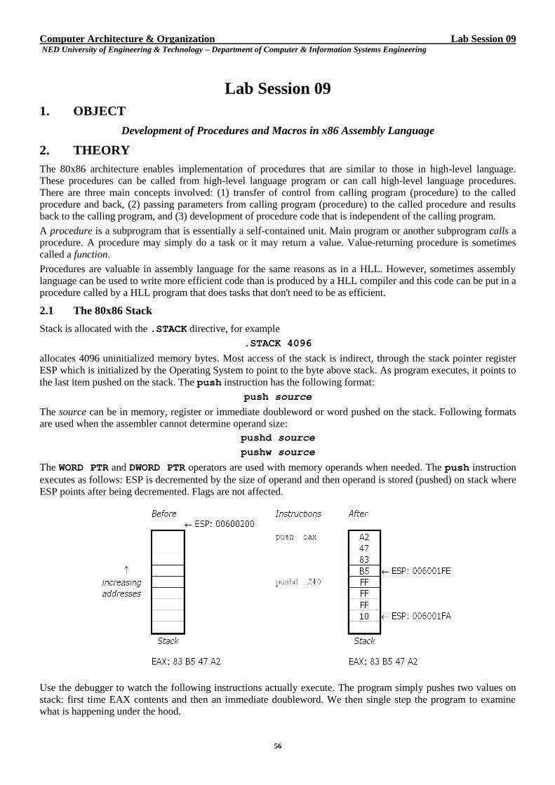
Computer Architecture & Organization Lab Session 09 NED University of Engineering & Technology – Department of Computer & Information Systems Engineering
56
Lab Session 09
1. OBJECT
Development of Procedures and Macros in x86 Assembly Language
2. THEORY
The 80x86 architecture enables implementation of procedures that are similar to those in high-level language.
These procedures can be called from high-level language program or can call high-level language procedures.
There are three main concepts involved: (1) transfer of control from calling program (procedure) to the called
procedure and back, (2) passing parameters from calling program (procedure) to the called procedure and results
back to the calling program, and (3) development of procedure code that is independent of the calling program.
A procedure is a subprogram that is essentially a self-contained unit. Main program or another subprogram calls a
procedure. A procedure may simply do a task or it may return a value. Value-returning procedure is sometimes
called a function.
Procedures are valuable in assembly language for the same reasons as in a HLL. However, sometimes assembly
language can be used to write more efficient code than is produced by a HLL compiler and this code can be put in a
procedure called by a HLL program that does tasks that don't need to be as efficient.
2.1 The 80x86 Stack
Stack is allocated with the .STACK directive, for example
.STACK 4096
allocates 4096 uninitialized memory bytes. Most access of the stack is indirect, through the stack pointer register
ESP which is initialized by the Operating System to point to the byte above stack. As program executes, it points to
the last item pushed on the stack. The push instruction has the following format:
push source
The source can be in memory, register or immediate doubleword or word pushed on the stack. Following formats
are used when the assembler cannot determine operand size:
pushd source
pushw source
The WORD PTR and DWORD PTR operators are used with memory operands when needed. The push instruction
executes as follows: ESP is decremented by the size of operand and then operand is stored (pushed) on stack where
ESP points after being decremented. Flags are not affected.
Use the debugger to watch the following instructions actually execute. The program simply pushes two values on
stack: first time EAX contents and then an immediate doubleword. We then single step the program to examine
what is happening under the hood.
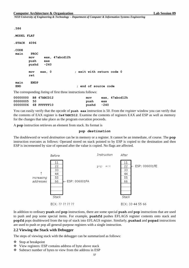
Computer Architecture & Organization Lab Session 09 NED University of Engineering & Technology – Department of Computer & Information Systems Engineering
57
.586
.MODEL FLAT
.STACK 4096
.CODE
main PROC
mov eax, 47abcd12h
push eax
pushd -240
mov eax, 0 ; exit with return code 0
ret
main ENDP
END ; end of source code
The corresponding listing of first three instructions follows:
00000000 B8 47ABCD12 mov eax, 47abcd12h
00000005 50 push eax
00000006 68 FFFFFF10 pushd -240
You can easily verify that the opcode of push eax instruction is 50. From the register window you can verify that
the contents of EAX register is 0x47ABCD12. Examine the contents of registers EAX and ESP as well as memory
for the changes that take place as the program execution proceeds.
A pop instruction retrieves an element from stack. Its format is
pop destination
The doubleword or word destination can be in memory or a register. It cannot be an immediate, of course. The pop
instruction executes as follows: Operand stored on stack pointed to by ESP is copied to the destination and then
ESP is incremented by size of operand after the value is copied. No flags are affected.
In addition to ordinary push and pop instructions, there are some special push and pop instructions that are used
to push and pop some special items. For example, pushfd pushes EFLAGS register contents onto stack and
popfd pops doubleword from the top of stack into EFLAGS register. Similarly, pushad and popad instructions
are used to push or pop all general-purpose registers with a single instruction.
2.2 Viewing the Stack with Debugger
The steps of viewing stack with the debugger can be summarized as follows:
Stop at breakpoint
View registers: ESP contains address of byte above stack
Subtract number of bytes to view from the address in ESP
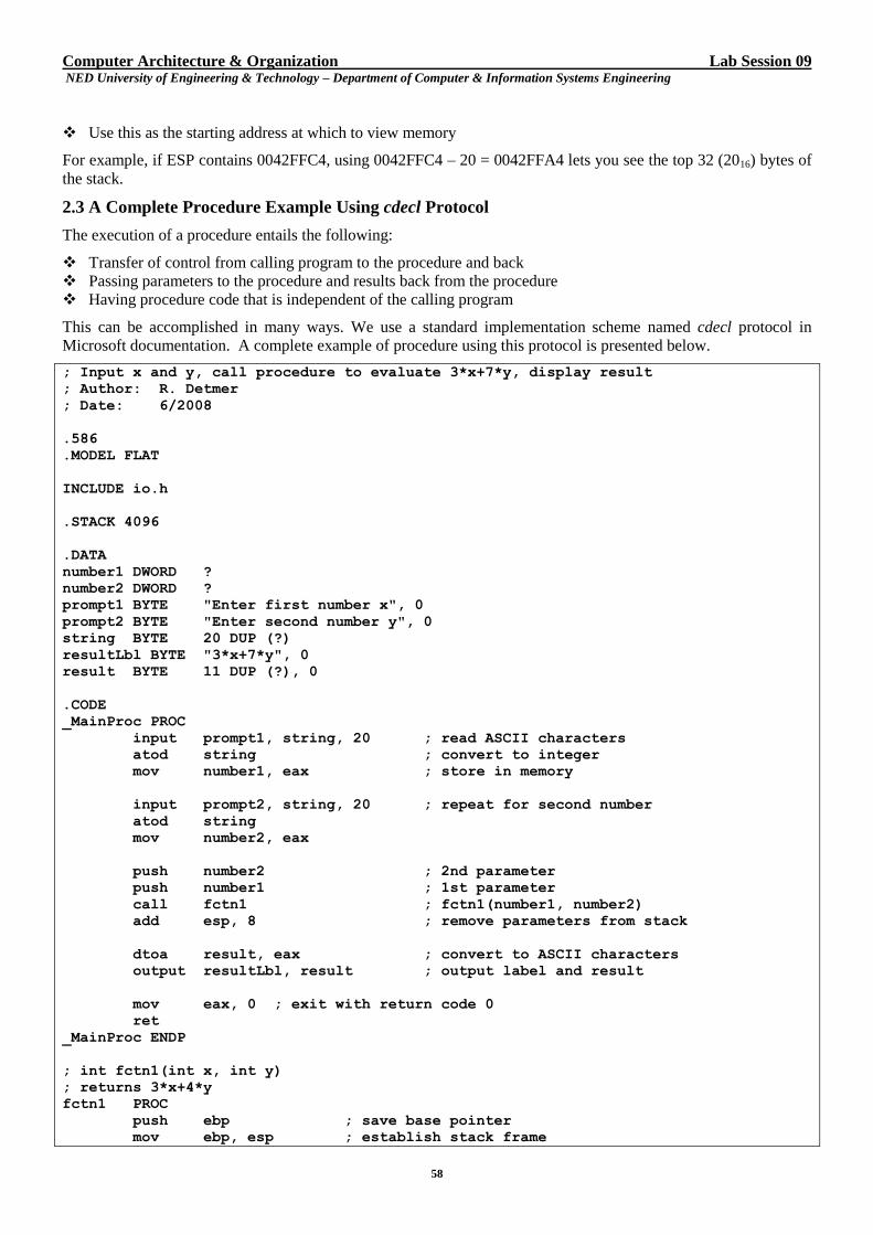
Computer Architecture & Organization Lab Session 09 NED University of Engineering & Technology – Department of Computer & Information Systems Engineering
58
Use this as the starting address at which to view memory
For example, if ESP contains 0042FFC4, using 0042FFC4 – 20 = 0042FFA4 lets you see the top 32 (2016) bytes of
the stack.
2.3 A Complete Procedure Example Using cdecl Protocol
The execution of a procedure entails the following:
Transfer of control from calling program to the procedure and back
Passing parameters to the procedure and results back from the procedure
Having procedure code that is independent of the calling program
This can be accomplished in many ways. We use a standard implementation scheme named cdecl protocol in
Microsoft documentation. A complete example of procedure using this protocol is presented below.
; Input x and y, call procedure to evaluate 3*x+7*y, display result
; Author: R. Detmer
; Date: 6/2008
.586
.MODEL FLAT
INCLUDE io.h
.STACK 4096
.DATA
number1 DWORD ?
number2 DWORD ?
prompt1 BYTE "Enter first number x", 0
prompt2 BYTE "Enter second number y", 0
string BYTE 20 DUP (?)
resultLbl BYTE "3*x+7*y", 0
result BYTE 11 DUP (?), 0
.CODE
_MainProc PROC
input prompt1, string, 20 ; read ASCII characters
atod string ; convert to integer
mov number1, eax ; store in memory
input prompt2, string, 20 ; repeat for second number
atod string
mov number2, eax
push number2 ; 2nd parameter
push number1 ; 1st parameter
call fctn1 ; fctn1(number1, number2)
add esp, 8 ; remove parameters from stack
dtoa result, eax ; convert to ASCII characters
output resultLbl, result ; output label and result
mov eax, 0 ; exit with return code 0
ret
_MainProc ENDP
; int fctn1(int x, int y)
; returns 3*x+4*y
fctn1 PROC
push ebp ; save base pointer
mov ebp, esp ; establish stack frame
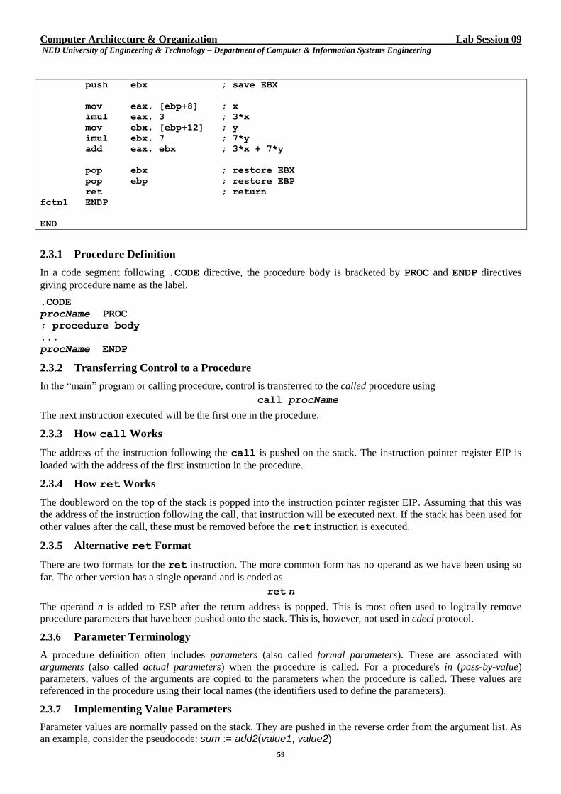
Computer Architecture & Organization Lab Session 09 NED University of Engineering & Technology – Department of Computer & Information Systems Engineering
59
push ebx ; save EBX
mov eax, [ebp+8] ; x
imul eax, 3 ; 3*x
mov ebx, [ebp+12] ; y
imul ebx, 7 ; 7*y
add eax, ebx ; 3*x + 7*y
pop ebx ; restore EBX
pop ebp ; restore EBP
ret ; return
fctn1 ENDP
END
2.3.1 Procedure Definition
In a code segment following .CODE directive, the procedure body is bracketed by PROC and ENDP directives
giving procedure name as the label.
.CODE
procName PROC
; procedure body
...
procName ENDP
2.3.2 Transferring Control to a Procedure
In the “main” program or calling procedure, control is transferred to the called procedure using
call procName
The next instruction executed will be the first one in the procedure.
2.3.3 How call Works
The address of the instruction following the call is pushed on the stack. The instruction pointer register EIP is
loaded with the address of the first instruction in the procedure.
2.3.4 How ret Works
The doubleword on the top of the stack is popped into the instruction pointer register EIP. Assuming that this was
the address of the instruction following the call, that instruction will be executed next. If the stack has been used for
other values after the call, these must be removed before the ret instruction is executed.
2.3.5 Alternative ret Format
There are two formats for the ret instruction. The more common form has no operand as we have been using so
far. The other version has a single operand and is coded as
ret n
The operand n is added to ESP after the return address is popped. This is most often used to logically remove
procedure parameters that have been pushed onto the stack. This is, however, not used in cdecl protocol.
2.3.6 Parameter Terminology
A procedure definition often includes parameters (also called formal parameters). These are associated with
arguments (also called actual parameters) when the procedure is called. For a procedure's in (pass-by-value)
parameters, values of the arguments are copied to the parameters when the procedure is called. These values are
referenced in the procedure using their local names (the identifiers used to define the parameters).
2.3.7 Implementing Value Parameters
Parameter values are normally passed on the stack. They are pushed in the reverse order from the argument list. As
an example, consider the pseudocode: sum := add2(value1, value2)
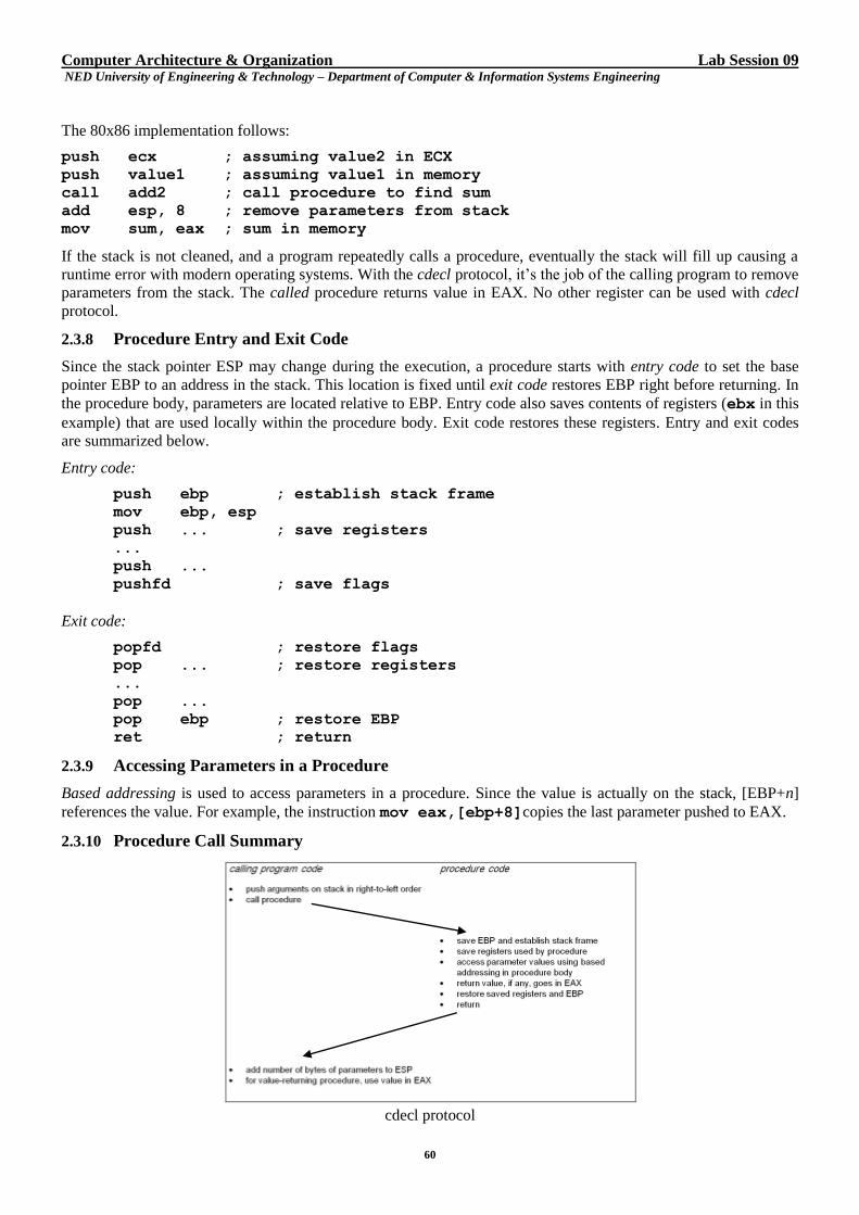
Computer Architecture & Organization Lab Session 09 NED University of Engineering & Technology – Department of Computer & Information Systems Engineering
60
The 80x86 implementation follows:
push ecx ; assuming value2 in ECX
push value1 ; assuming value1 in memory
call add2 ; call procedure to find sum
add esp, 8 ; remove parameters from stack
mov sum, eax ; sum in memory
If the stack is not cleaned, and a program repeatedly calls a procedure, eventually the stack will fill up causing a
runtime error with modern operating systems. With the cdecl protocol, it’s the job of the calling program to remove
parameters from the stack. The called procedure returns value in EAX. No other register can be used with cdecl
protocol.
2.3.8 Procedure Entry and Exit Code
Since the stack pointer ESP may change during the execution, a procedure starts with entry code to set the base
pointer EBP to an address in the stack. This location is fixed until exit code restores EBP right before returning. In
the procedure body, parameters are located relative to EBP. Entry code also saves contents of registers (ebx in this
example) that are used locally within the procedure body. Exit code restores these registers. Entry and exit codes
are summarized below.
Entry code:
push ebp ; establish stack frame
mov ebp, esp
push ... ; save registers
...
push ...
pushfd ; save flags
Exit code:
popfd ; restore flags
pop ... ; restore registers
...
pop ...
pop ebp ; restore EBP
ret ; return
2.3.9 Accessing Parameters in a Procedure
Based addressing is used to access parameters in a procedure. Since the value is actually on the stack, [EBP+n]
references the value. For example, the instruction mov eax,[ebp+8]copies the last parameter pushed to EAX.
2.3.10 Procedure Call Summary
cdecl protocol
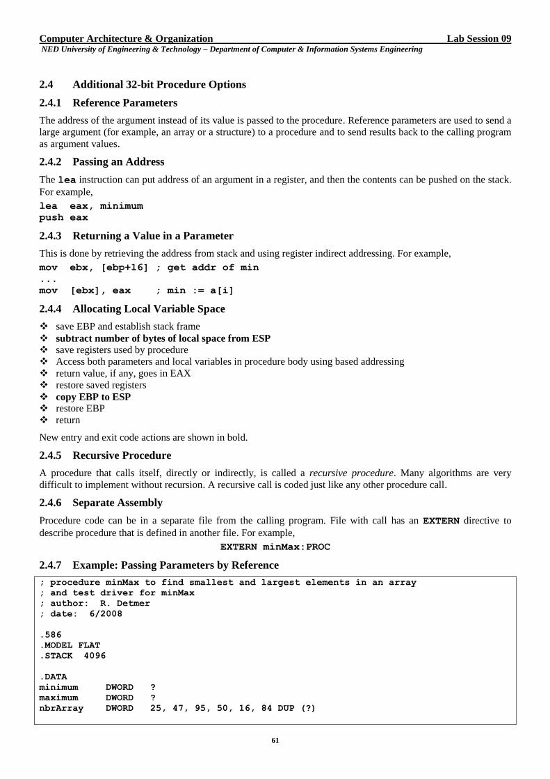
Computer Architecture & Organization Lab Session 09 NED University of Engineering & Technology – Department of Computer & Information Systems Engineering
61
2.4 Additional 32-bit Procedure Options
2.4.1 Reference Parameters
The address of the argument instead of its value is passed to the procedure. Reference parameters are used to send a
large argument (for example, an array or a structure) to a procedure and to send results back to the calling program
as argument values.
2.4.2 Passing an Address
The lea instruction can put address of an argument in a register, and then the contents can be pushed on the stack.
For example,
lea eax, minimum
push eax
2.4.3 Returning a Value in a Parameter
This is done by retrieving the address from stack and using register indirect addressing. For example,
mov ebx, [ebp+16] ; get addr of min
...
mov [ebx], eax ; min := a[i]
2.4.4 Allocating Local Variable Space
save EBP and establish stack frame
subtract number of bytes of local space from ESP save registers used by procedure
Access both parameters and local variables in procedure body using based addressing
return value, if any, goes in EAX
restore saved registers
copy EBP to ESP restore EBP
return
New entry and exit code actions are shown in bold.
2.4.5 Recursive Procedure
A procedure that calls itself, directly or indirectly, is called a recursive procedure. Many algorithms are very
difficult to implement without recursion. A recursive call is coded just like any other procedure call.
2.4.6 Separate Assembly
Procedure code can be in a separate file from the calling program. File with call has an EXTERN directive to
describe procedure that is defined in another file. For example,
EXTERN minMax:PROC
2.4.7 Example: Passing Parameters by Reference
; procedure minMax to find smallest and largest elements in an array
; and test driver for minMax
; author: R. Detmer
; date: 6/2008
.586
.MODEL FLAT
.STACK 4096
.DATA
minimum DWORD ?
maximum DWORD ?
nbrArray DWORD 25, 47, 95, 50, 16, 84 DUP (?)
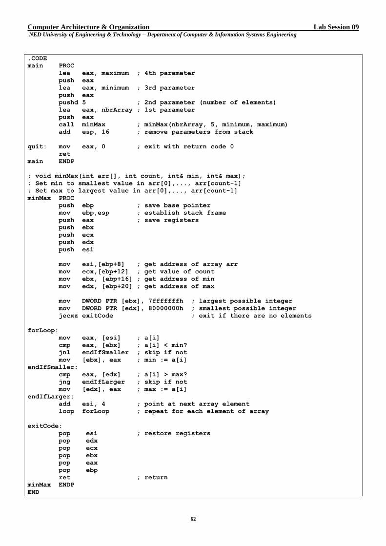
Computer Architecture & Organization Lab Session 09 NED University of Engineering & Technology – Department of Computer & Information Systems Engineering
62
.CODE
main PROC
lea eax, maximum ; 4th parameter
push eax
lea eax, minimum ; 3rd parameter
push eax
pushd 5 ; 2nd parameter (number of elements)
lea eax, nbrArray ; 1st parameter
push eax
call minMax ; minMax(nbrArray, 5, minimum, maximum)
add esp, 16 ; remove parameters from stack
quit: mov eax, 0 ; exit with return code 0
ret
main ENDP
; void minMax(int arr[], int count, int& min, int& max);
; Set min to smallest value in arr[0],..., arr[count-1]
; Set max to largest value in arr[0],..., arr[count-1]
minMax PROC
push ebp ; save base pointer
mov ebp,esp ; establish stack frame
push eax ; save registers
push ebx
push ecx
push edx
push esi
mov esi,[ebp+8] ; get address of array arr
mov ecx,[ebp+12] ; get value of count
mov ebx, [ebp+16] ; get address of min
mov edx, [ebp+20] ; get address of max
mov DWORD PTR [ebx], 7fffffffh ; largest possible integer
mov DWORD PTR [edx], 80000000h ; smallest possible integer
jecxz exitCode ; exit if there are no elements
forLoop:
mov eax, [esi] ; a[i]
cmp eax, [ebx] ; a[i] < min?
jnl endIfSmaller ; skip if not
mov [ebx], eax ; min := a[i]
endIfSmaller:
cmp eax, [edx] ; a[i] > max?
jng endIfLarger ; skip if not
mov [edx], eax ; max := a[i]
endIfLarger:
add esi, 4 ; point at next array element
loop forLoop ; repeat for each element of array
exitCode:
pop esi ; restore registers
pop edx
pop ecx
pop ebx
pop eax
pop ebp
ret ; return
minMax ENDP
END
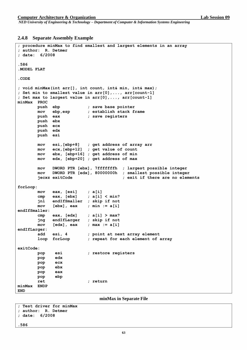
Computer Architecture & Organization Lab Session 09 NED University of Engineering & Technology – Department of Computer & Information Systems Engineering
63
2.4.8 Separate Assembly Example
; procedure minMax to find smallest and largest elements in an array
; author: R. Detmer
; date: 6/2008
.586
.MODEL FLAT
.CODE
; void minMax(int arr[], int count, int& min, int& max);
; Set min to smallest value in arr[0],..., arr[count-1]
; Set max to largest value in arr[0],..., arr[count-1]
minMax PROC
push ebp ; save base pointer
mov ebp,esp ; establish stack frame
push eax ; save registers
push ebx
push ecx
push edx
push esi
mov esi,[ebp+8] ; get address of array arr
mov ecx,[ebp+12] ; get value of count
mov ebx, [ebp+16] ; get address of min
mov edx, [ebp+20] ; get address of max
mov DWORD PTR [ebx], 7fffffffh ; largest possible integer
mov DWORD PTR [edx], 80000000h ; smallest possible integer
jecxz exitCode ; exit if there are no elements
forLoop:
mov eax, [esi] ; a[i]
cmp eax, [ebx] ; a[i] < min?
jnl endIfSmaller ; skip if not
mov [ebx], eax ; min := a[i]
endIfSmaller:
cmp eax, [edx] ; a[i] > max?
jng endIfLarger ; skip if not
mov [edx], eax ; max := a[i]
endIfLarger:
add esi, 4 ; point at next array element
loop forLoop ; repeat for each element of array
exitCode:
pop esi ; restore registers
pop edx
pop ecx
pop ebx
pop eax
pop ebp
ret ; return
minMax ENDP
END
minMax in Separate File
; Test driver for minMax
; author: R. Detmer
; date: 6/2008
.586
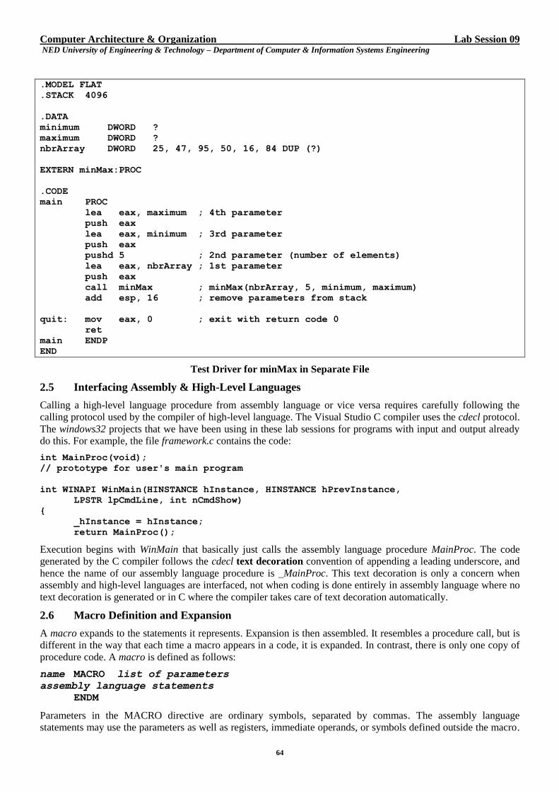
Computer Architecture & Organization Lab Session 09 NED University of Engineering & Technology – Department of Computer & Information Systems Engineering
64
.MODEL FLAT
.STACK 4096
.DATA
minimum DWORD ?
maximum DWORD ?
nbrArray DWORD 25, 47, 95, 50, 16, 84 DUP (?)
EXTERN minMax:PROC
.CODE
main PROC
lea eax, maximum ; 4th parameter
push eax
lea eax, minimum ; 3rd parameter
push eax
pushd 5 ; 2nd parameter (number of elements)
lea eax, nbrArray ; 1st parameter
push eax
call minMax ; minMax(nbrArray, 5, minimum, maximum)
add esp, 16 ; remove parameters from stack
quit: mov eax, 0 ; exit with return code 0
ret
main ENDP
END
Test Driver for minMax in Separate File
2.5 Interfacing Assembly & High-Level Languages
Calling a high-level language procedure from assembly language or vice versa requires carefully following the
calling protocol used by the compiler of high-level language. The Visual Studio C compiler uses the cdecl protocol.
The windows32 projects that we have been using in these lab sessions for programs with input and output already
do this. For example, the file framework.c contains the code:
int MainProc(void);
// prototype for user's main program
int WINAPI WinMain(HINSTANCE hInstance, HINSTANCE hPrevInstance,
LPSTR lpCmdLine, int nCmdShow)
{
_hInstance = hInstance;
return MainProc();
Execution begins with WinMain that basically just calls the assembly language procedure MainProc. The code
generated by the C compiler follows the cdecl text decoration convention of appending a leading underscore, and
hence the name of our assembly language procedure is _MainProc. This text decoration is only a concern when
assembly and high-level languages are interfaced, not when coding is done entirely in assembly language where no
text decoration is generated or in C where the compiler takes care of text decoration automatically.
2.6 Macro Definition and Expansion
A macro expands to the statements it represents. Expansion is then assembled. It resembles a procedure call, but is
different in the way that each time a macro appears in a code, it is expanded. In contrast, there is only one copy of
procedure code. A macro is defined as follows:
name MACRO list of parameters
assembly language statements
ENDM
Parameters in the MACRO directive are ordinary symbols, separated by commas. The assembly language
statements may use the parameters as well as registers, immediate operands, or symbols defined outside the macro.
Computer Architecture & Organization Lab Session 09 NED University of Engineering & Technology – Department of Computer & Information Systems Engineering
65
A macro definition can appear anywhere in an assembly language source code file as long as the definition comes
before the first statement that calls the macro. It is good programming practice to place macro definitions near the
beginning of a source file or in a separate file that is included with the INCLUDE directive.
Given the definition:
add2 MACRO nbr1, nbr2
; put sum of two doubleword parameters in EAX
mov eax, nbr1
add eax, nbr2
ENDM
the macro call
add2 value, 30 ; value + 30
expands to
; put sum of two doubleword parameters in EAX
mov eax, value
add eax, 30
Similarly, the macro call
add2 eax, ebx ; sum of two values
expands to
; put sum of two doubleword parameters in EAX mov eax, eax
add eax, ebx
Each macro in io.h expands to a statement that calls a procedure, for example
atod MACRO source ; convert ASCII string
; to integer in EAX
lea eax,source ; source address to AX
push eax ; source parameter on stack
call atodproc ; call atodproc(source)
add esp, 4 ; remove parameter
ENDM
3. EXERCISES
a) For each of these exercises follow the cdecl protocol for the specified procedure and write a short
console32 or window32 test-driver program to test the procedure.
i. Write a procedure discr that could be described in C/C++ by
int discr(int a, int b, int c)
// return the discriminant
that is, is name is discr, it has three integer parameters, and it is a value-returning procedure.

Computer Architecture & Organization Lab Session 09 NED University of Engineering & Technology – Department of Computer & Information Systems Engineering
66
Computer Architecture & Organization Lab Session 09 NED University of Engineering & Technology – Department of Computer & Information Systems Engineering
67
ii. Write a value-returning procedure min2 to find the smaller of two doubleword integer parameters.
Computer Architecture & Organization Lab Session 09 NED University of Engineering & Technology – Department of Computer & Information Systems Engineering
68
iii. Write a value-returning procedure max3 to find the largest of three double-word integers.

Computer Architecture & Organization Lab Session 09 NED University of Engineering & Technology – Department of Computer & Information Systems Engineering
69
Computer Architecture & Organization Lab Session 09 NED University of Engineering & Technology – Department of Computer & Information Systems Engineering
70
iv. Implement a procedure in assembly language that counts and returns the number of characters in a
null terminated string whose address is passed to the procedure.
Computer Architecture & Organization Lab Session 09 NED University of Engineering & Technology – Department of Computer & Information Systems Engineering
71
Computer Architecture & Organization Lab Session 09 NED University of Engineering & Technology – Department of Computer & Information Systems Engineering
72
v. Write a value-returning procedure search to search an array of doublewords for a specified
doubleword value. Procedure search will have three parameters: the value to be searched, the pointer
to the array and size of the array (passed as doubleword). Return the position at which the element is
found or return 0 if the value does not appear in array. Remember array indices begin at 1 not at 0.
Computer Architecture & Organization Lab Session 09 NED University of Engineering & Technology – Department of Computer & Information Systems Engineering
73
b) Assemble each macro definition below in a short console32 test-driver program.
i. Write a definition of a macro add3 that has three doubleword integer parameters and puts the sum of
the three numbers in the EAX register.
Computer Architecture & Organization Lab Session 09 NED University of Engineering & Technology – Department of Computer & Information Systems Engineering
74
ii. Write a definition of a macro max2 that has two doubleword integer parameters and puts the
maximum of the two numbers in the EAX register.
iii. Write a definition of a macro min3 that has three doubleword integer parameters and puts the
minimum of the three numbers in the EAX register.
iv. Write a definition of a macro toUpper with one parameter; the address of a byte in memory. The code
generated by the macro will examine the byte, and if it is the ASCII code for a lowercase letter,
replace it by the ASCII code for the corresponding uppercase letter.
Computer Architecture & Organization Lab Session 10 NED University of Engineering & Technology – Department of Computer & Information Systems Engineering
75
Lab Session 10
1. OBJECT
Familiarization with SPIM – a MIPS simulator
2. THEORY
SPIM is simulator that lets you execute assembly code designed for the MIPS R2000/R3000 architecture. We shall
use PCSpim, a PC version of the simulator. When you invoke the simulator, a window will pop up with four
panels.
Register Display This displays all the registers in the MIPS microprocessor. Note that the general registers $0-$31 are shown as
R0-R31.
Text Segment This displays instructions of program.
Data Segment This shows the data stored in memory.
SPIM Messages This displays all error messages for SPIM. If your program has syntax errors, it will show up here after your
program has been loaded.
As an example of text segment, consider the following sample line in this panel is
[0x00400000] 0x8fa40000 lw $4,0($29) ; 140: lw $a0,0($sp)
[0x00400000] is the memory address of the instruction. The address is encoded in hexadecimal.
0x8fa40000 is the 32-bit word machine code for the instruction.
lw $4, 0($29) is the instruction's description in assembly language.
140:lw $a0, 0($sp) is the actual line from your assembly file that produced the instruction.
3. PROCEDURE
a) Create the following program using notepad and call this program first.s. (The extension .s is for
assembly file. Alternatively, you may use the extension .asm)
# comments are delimited by hash marks
# This program repeated additions to multiply $20 and $21, and puts the product
# in $22
main: move $22,$0 # This initializes $22 to zero
move $23,$20 # $23 is a temporary register used as a counter
loop: beq $0,$23,quit # if the counter is zero then quit
add $22,$22,$21 # $22 = $22 + $21
addi $23,$23,-1 # $23 = $23 - 1 (update counter)
j loop
quit: jr $31
b) Use file > open to load first.s. Note that the first.s is loaded at address 0x00400024. The set of
instructions that starts from 0x0040000 is some housekeeping to be done before executing first.s.
These instructions are:
lw $4, 0($29)
addiu $5, $29, 4
addiu $6, $5, 4
sll $2, $4, 2
addu $6, $6, $2
jal 0x00400024 [main]
nop
Computer Architecture & Organization Lab Session 10 NED University of Engineering & Technology – Department of Computer & Information Systems Engineering
76
ori $2, $0, 10
syscall
c) Use simulator > set value to initialize the registers $20 (R20) and $21 (R21) to values 3 and 4
respectively. Notice that the changes appear in the Register Display.
d) Run the program using simulator > go. It will pop up a window indicating the PC to begin execution
(0x00400000). Note that the default address of where to start running is 0x00400000, which is okay
because we want to do the "housekeeping".
e) When the program stops, check if $22 (R22) has the product 3 x 4 = 12 (or 0xc in hexadecimal).
Steps (f) to (k) will highlight an important debugging technique single-stepping i.e.; executing one
instruction at a time (rather than running the whole program at once and obtaining the net result) and
observing the incremental results.
f) Use simulator > set value to initialize the registers $20 (R20) and $21 (R21) to values 3 and 4
respectively. Notice that the changes appear in the Register Display.
g) Reload first.s using file > open (or alternatively, use simulator > reload). The PC register (in the
upper left corner) should have reverted back to 0x00400000. The first instruction is highlighted because
it is at the address currently held in the program counter (PC) register, and, thus, is the next instruction to
be executed.
h) Single-step through instructions using simulator > single step. First of all, instruction lw $4,
0($29)will be executed. This first instruction loads a value into register $4 (R4)
i. What value was loaded? (Observe the register display).
ii. What are the contents of register $sp ($29)?
Looking at the third panel from the top i.e. data segment, you can confirm that the correct value was
read from memory.
i) Executing the first instruction also changes the contents of the PC register. What is the new value of the
PC?
j) Single-step so that instruction at address 0x00400008 is highlighted. This instruction is addiu for
ADD Immediate Unsigned, which means add a constant (in this case 4) to a register (R29) and put it
in another register (R5).
i. What value was there in R5 before the execution of this instruction?
ii. What value was written into R5 as a result of executing this instruction?
Verify that R5 gets the correct value.
k) Single-step so that instruction at address 0x00400008 is highlighted. This instruction is another addiu.
i. What value was there in R5 before the execution of this instruction?
ii. What value was written into R5 as a result of executing this instruction?
Verify that R5 gets the correct value.
Following steps will illustrate another debugging technique i.e. breakpoints.
l) Initialize $20 and $21 to the values 4 and 5, respectively, as before. Check to see that the values are
properly loaded into the registers.
m) Reload first.s.
n) Use simulator > breakpoints to set the breakpoints at main which is at address 0x00400024 and
loop which is at address 0x0040002C.
Notice the instructions at the breakpoints have been replaced by an instruction break $1. This is a
special instruction recognized by the processor. Whenever the processor sees this instruction it goes to a
special location to execute a program, called interrupt handler. This is an example of software interrupt.
The interrupt handler determines the proper operation to be executed at the breakpoint; updates register
values, and so on.
Computer Architecture & Organization Lab Session 10 NED University of Engineering & Technology – Department of Computer & Information Systems Engineering
77
o) Run the program using either the function key F5 or simulator > go. A window will be popped up asking
for the starting address to begin execution. The default appears in the window and you simply need to click
OK. Another window will be displayed informing that a breakpoint was encountered at the address
0x00400024.
Record the values in the following registers:
Register Value
R20
R21
R22
R23
(When a breakpoint is set, the program stops after executing the instruction just before the instruction at
which the breakpoint is set).
p) Click CONTINUE to let the program run. You will hit the breakpoint at the address 0x0040002C for the
first time.
Record the values in the following registers:
Register Value
R20
R21
R22
R23
q) Continue running the program until you hit the breakpoint at loop again i.e.; at the address 0x0040002C.
(second time)
Record the values in the following registers:
Register Value
R20
R21
R22
R23
r) Continue running the program until you hit the breakpoint at loop again i.e.; at the address 0x0040002C.
(third time)
Record the values in the following registers:
Register Value
R20
R21
Computer Architecture & Organization Lab Session 10 NED University of Engineering & Technology – Department of Computer & Information Systems Engineering
78
R22
R23
s) Continue running the program until you hit the breakpoint at loop again i.e.; at the address 0x0040002C.
(fourth time)
Record the values in the following registers:
Register Value
R20
R21
R22
R23
t) Continue running the program until you hit the breakpoint at loop again i.e.; at the address 0x0040002C.
(fifth time)
Record the values in the following registers:
Register Value
R20
R21
R22
R23
Computer Architecture & Organization Lab Session 11 NED University of Engineering & Technology – Department of Computer & Information Systems Engineering
79
Lab Session 11
1. OBJECT
Learning use of SPIM console and appreciate system calls provided by the SPIM
2. THEORY
SPIM provides several windows that show what is happening in several areas of the simulated machine. One of
these windows is console. This is the window that simulates the interface to the “user” of the program you are
running. Text messages to the user are displayed here, and input from the user is entered here.
This lab demonstrates the use of console as well as data segment. This window displays the data segments of the
memory for the current program. The most important portion of this window is simply labeled “Data” and includes
user data (defined by .word, .space, .asciiz, etc. These directives will be defined later). The remaining
portions show data used by the system.
3. PROCEDURE
a) Create the following program using notepad and call this program second.s.
.data
# strings to be output to the terminal (console)
greet: .asciiz "Well Come to SPIM console!\n"
prompt: .asciiz "Please enter a number followed by the <enter>:"
result: .asciiz "Your number, incremented, is:"
linefeed: .asciiz "\n"
.text
main:
# display greeting message
li $v0,4 # code for print_string
la $a0,greet # point $a0 to the greeting string
syscall # print the string
# display prompt message
li $v0,4 # code for print_string
la $a0,prompt # point $a0 to prompt string
syscall # print the prompt
# get an integer from the user
li $v0,5 # code for read_int
syscall # get an int from user returned in $v0
move $s0,$v0 # copy the resulting int to $s0
addi $s0,$s0,1
# print result string
li $v0,4 # code for print_string
la $a0,result # point $a0 to string
syscall # print the string
Computer Architecture & Organization Lab Session 11 NED University of Engineering & Technology – Department of Computer & Information Systems Engineering
80
# print out the result
li $v0,1 # code for print_int
move $a0,$s0 # put number in $a0
syscall # print out the number
#print linefeed
li $v0,4 # code for print_string
la $a0,linefeed # point $a0 to linefeed string
syscall # print linefeed
li $v0,10 # code for exit
syscall # exit program
The above program has two parts. First is the data segment, tagged with the .data directive. The data segment is
used to allocate storage and initialize global variables. The above program allocates four string variables greet,
prompt, result and linefeed. The .asciiz directive indicates that this variable is an ASCII string that should be
terminated with a zero (that's what the z means). For instance, the assembler will allocate 28 bytes of space (one for
each character and one more for a terminating zero) for the first variable greet and load it with the ASCII values for
the characters, followed by a zero.
Second is the text segment, indicated by the .text directive. This is where we put the instructions we want the
processor to execute. In the above program, there is a single function, which is called main. The name main is
special; it will be the first function of our program that gets called.
Following is a brief description of instructions used in the program.
li is mnemonic for load immediate; that means put the specified constant into the register mentioned in
the instruction.
la is mnemonic for load address; that means put the address of specified variable into the register
mentioned in the instruction.
syscall is mnemonic for system call; SPIM provides a number of operating system services that aren't
really a part of MIPS assembly language, but are useful for playing with little assembly programs. We indicate
to SPIM which system call to perform by putting a particular number in register $v0. For instance, system call
number 4 is print_string which interprets the contents of register $a0 as the address of a null-terminated
string (i.e., a string that ends with a zero) and copies the string to the console.
b) Note that the pseudo la instruction is converted into the MIPS primitive lui (for load upper immediate).
The real MIPS instruction that appears for the first la is the following:
lui $4, 4097
Justify the use of constant 4097 in the above instruction.
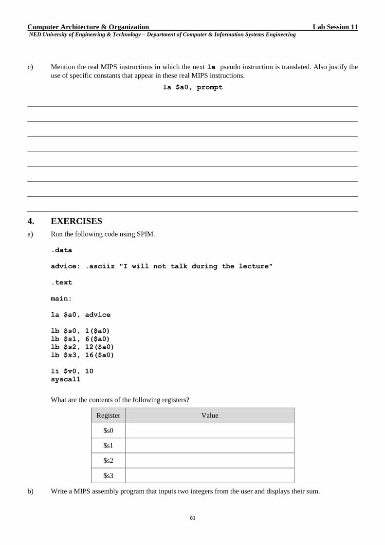
Computer Architecture & Organization Lab Session 11 NED University of Engineering & Technology – Department of Computer & Information Systems Engineering
81
c) Mention the real MIPS instructions in which the next la pseudo instruction is translated. Also justify the
use of specific constants that appear in these real MIPS instructions.
la $a0, prompt
4. EXERCISES
a) Run the following code using SPIM.
.data
advice: .asciiz "I will not talk during the lecture"
.text
main:
la $a0, advice
lb $s0, 1($a0)
lb $s1, 6($a0)
lb $s2, 12($a0)
lb $s3, 16($a0)
li $v0, 10
syscall
What are the contents of the following registers?
Register Value
$s0
$s1
$s2
$s3
b) Write a MIPS assembly program that inputs two integers from the user and displays their sum.

Computer Architecture & Organization Lab Session 11 NED University of Engineering & Technology – Department of Computer & Information Systems Engineering
82
Computer Architecture & Organization Lab Session 13 NED University of Engineering & Technology – Department of Computer & Information Systems Engineering
83
Lab Session 12
a) OBJECT
Developing Procedures in MIPS Assembly Language
b) THEORY
A convention regarding the use of registers is necessary when software is a team effort. In this case each member
must know how registers are supposed to be used such that his piece of software does not conflict with others. This
is required by the compiler that needs to know about it. It is mostly because an executable can be created from
pieces that are compiled separately; the compiler then makes the assumption that they all have been compiled using
the same convention. To compile a procedure, the compiler must know which registers need to be preserved and
which can be modified without worry. These rules for register-use are also called procedure call conventions.
Following steps are taken for a procedure call in MIPS assembly.
The caller must:
Put the parameters in registers $a0 - $a3. If there are more than four parameters, the additional parameters
are pushed onto the stack.
Save any of the caller-saved registers ($t0 - $t9) which are used by the caller.
Execute jal to jump to the function.
The callee must: (as part of the function preamble)
Create a stack frame, by subtracting the frame size from the stack pointer $sp. A stack frame is the space
allocated on stack to be used for bookkeeping data.
Note that the minimum stack frame size in the MIPS software architecture is 32 bytes, so even if you don't
need all of this space, you should still make your stack frames this large.
Save any callee-saved registers ($s0 - $s7, $fp, $ra) which are used by the callee. Note that the frame
pointer ($fp) must always be saved. The return address $ra needs to be saved only by functions which make
function calls themselves.
Set the frame pointer to the stack pointer, plus the frame size.
The callee then executes the body of the function.
To return from a function, the callee must:
Put the return value, if any, into register $v0.
Restore callee-saved registers.
Jump back to $ra, using the jr instruction.
To clean up after a function call, the caller must:
Restore the caller-saved registers.
If any arguments were passed on the stack (instead of in $a0 - $a3), pop them of the stack.
Extract the return value, if any, from register $v0.
We shall use the convention that a procedure stores $fp at the top of its stack frame, followed by $ra, then any of
the callee-saved registers ($s0 - $s7), and finally any of the caller-saved registers ($t0 - $t9) that need to be
preserved.
There is nothing to prevent you from ignoring these rules. After all they are not enforced by hardware mechanisms.
But, if you choose not to follow these rules, then chances are you call for trouble in the form of software bugs and
some of these bugs may be very vicious.
2.1 Example: Computing Fibonacci Sequence
The Fibonacci sequence has the following recursive definition: Let F(n) be the nth element (where n > 0) in the
sequence.
If n < 2, then F(n) = 1. (the base case)
Otherwise, F(n) = F(n - 1) + F(n - 2). (the recursive case)
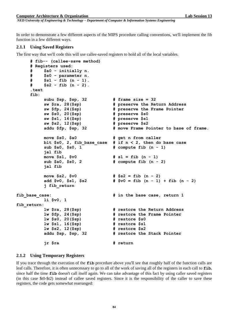
Computer Architecture & Organization Lab Session 13 NED University of Engineering & Technology – Department of Computer & Information Systems Engineering
84
In order to demonstrate a few different aspects of the MIPS procedure calling conventions, we'll implement the fib
function in a few different ways.
2.1.1 Using Saved Registers
The first way that we'll code this will use callee-saved registers to hold all of the local variables.
# fib-- (callee-save method)
# Registers used:
# $a0 - initially n.
# $s0 - parameter n.
# $s1 - fib (n - 1).
# $s2 - fib (n - 2).
.text
fib:
subu $sp, $sp, 32 # frame size = 32
sw $ra, 28($sp) # preserve the Return Address
sw $fp, 24($sp) # preserve the Frame Pointer
sw $s0, 20($sp) # preserve $s0
sw $s1, 16($sp) # preserve $s1
sw $s2, 12($sp) # preserve $s2
addu $fp, $sp, 32 # move Frame Pointer to base of frame.
move $s0, $a0 # get n from caller
blt $s0, 2, fib_base_case # if n < 2, then do base case
sub $a0, $s0, 1 # compute fib (n - 1)
jal fib
move $s1, $v0 # s1 = fib (n - 1)
sub $a0, $s0, 2 # compute fib (n - 2)
jal fib
move $s2, $v0 # $s2 = fib (n - 2)
add $v0, $s1, $s2 # $v0 = fib (n - 1) + fib (n - 2)
j fib_return
fib_base_case: # in the base case, return 1
li $v0, 1
fib_return:
lw $ra, 28($sp) # restore the Return Address
lw $fp, 24($sp) # restore the Frame Pointer
lw $s0, 20($sp) # restore $s0
lw $s1, 16($sp) # restore $s1
lw $s2, 12($sp) # restore $s2
addu $sp, $sp, 32 # restore the Stack Pointer
jr $ra # return
2.1.2 Using Temporary Registers
If you trace through the execution of the fib procedure above you'll see that roughly half of the function calls are
leaf calls. Therefore, it is often unnecessary to go to all of the work of saving all of the registers in each call to fib,
since half the time fib doesn't call itself again. We can take advantage of this fact by using caller saved registers
(in this case $t0-$t2) instead of callee saved registers. Since it is the responsibility of the caller to save these
registers, the code gets somewhat rearranged:
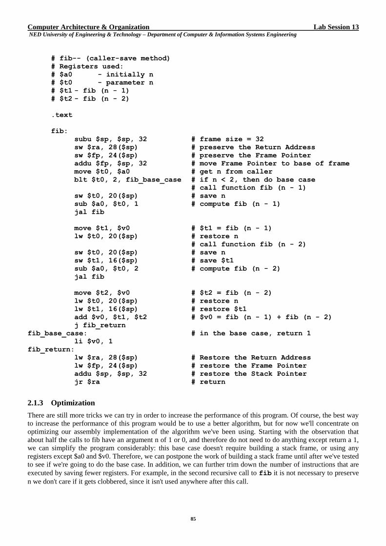
Computer Architecture & Organization Lab Session 13 NED University of Engineering & Technology – Department of Computer & Information Systems Engineering
85
# fib-- (caller-save method)
# Registers used:
# $a0 - initially n
# $t0 - parameter n
# $t1 - fib (n - 1)
# $t2 - fib (n - 2)
.text
fib:
subu $sp, $sp, 32 # frame size = 32
sw $ra, 28($sp) # preserve the Return Address
sw $fp, 24($sp) # preserve the Frame Pointer
addu $fp, $sp, 32 # move Frame Pointer to base of frame
move $t0, $a0 # get n from caller
blt $t0, 2, fib_base_case # if n < 2, then do base case
# call function fib (n - 1)
sw $t0, 20($sp) # save n
sub $a0, $t0, 1 # compute fib (n - 1)
jal fib
move $t1, $v0 # $t1 = fib (n - 1)
lw $t0, 20($sp) # restore n
# call function fib (n - 2)
sw $t0, 20($sp) # save n
sw $t1, 16($sp) # save $t1
sub $a0, $t0, 2 # compute fib (n - 2)
jal fib
move $t2, $v0 # $t2 = fib (n - 2)
lw $t0, 20($sp) # restore n
lw $t1, 16($sp) # restore $t1
add $v0, $t1, $t2 # $v0 = fib (n - 1) + fib (n - 2)
j fib_return
fib_base_case: # in the base case, return 1
li $v0, 1
fib_return:
lw $ra, 28($sp) # Restore the Return Address
lw $fp, 24($sp) # restore the Frame Pointer
addu $sp, $sp, 32 # restore the Stack Pointer
jr $ra # return
2.1.3 Optimization
There are still more tricks we can try in order to increase the performance of this program. Of course, the best way
to increase the performance of this program would be to use a better algorithm, but for now we'll concentrate on
optimizing our assembly implementation of the algorithm we've been using. Starting with the observation that
about half the calls to fib have an argument n of 1 or 0, and therefore do not need to do anything except return a 1,
we can simplify the program considerably: this base case doesn't require building a stack frame, or using any
registers except $a0 and $v0. Therefore, we can postpone the work of building a stack frame until after we've tested
to see if we're going to do the base case. In addition, we can further trim down the number of instructions that are
executed by saving fewer registers. For example, in the second recursive call to fib it is not necessary to preserve
n we don't care if it gets clobbered, since it isn't used anywhere after this call.
Computer Architecture & Organization Lab Session 13 NED University of Engineering & Technology – Department of Computer & Information Systems Engineering
86
# fib-- (hacked-up caller-save method)
# Registers used:
# $a0 - initially n
# $t0 - parameter n
# $t1 - fib (n - 1)
# $t2 - fib (n - 2)
.text
fib:
bgt $a0, 1, fib_recurse # if n < 2, then just return a 1,
li $v0, 1 # don't bother to build a stack frame
jr $ra
# otherwise, set things up to handle
fib_recurse: # the recursive case
subu $sp, $sp, 32 # frame size = 32
sw $ra, 28($sp) # preserve the Return Address
sw $fp, 24($sp) # preserve the Frame Pointer
addu $fp, $sp, 32 # move Frame Pointer to base of frame
move $t0, $a0 # get n from caller
# compute fib (n - 1)
sw $t0, 20($sp) # preserve n
sub $a0, $t0, 1 # compute fib (n - 1)
jal fib
move $t1, $v0 # t1 = fib (n - 1)
lw $t0, 20($sp) # restore n
# compute fib (n - 2)
sw $t1, 16($sp) # preserve $t1
sub $a0, $t0, 2 # compute fib (n - 2)
jal fib
move $t2, $v0 # t2 = fib (n - 2)
lw $t1, 16($sp) # restore $t1
add $v0, $t1, $t2 # $v0 = fib (n - 1) + fib (n - 2)
lw $ra, 28($sp) # restore Return Address
lw $fp, 24($sp) # restore Frame Pointer
addu $sp, $sp, 32 # restore Stack Pointer
jr $ra # return
c) EXERCISES
a) Write a MIPS assembly program that asks user to enter an integer n and displays nth Fibonacci number.
You should use all the procedures (of course, one at a time) described in the lab. Test your programs using
SPIM simulator. (Please attach separate program sheet)
b) Write a MIPS assembly program that asks user to enter an integer n and displays its factorial. You must use
a recursive procedure for the computation. Test your programs using SPIM simulator.

Computer Architecture & Organization Lab Session 13 NED University of Engineering & Technology – Department of Computer & Information Systems Engineering
87
Computer Architecture & Organization Lab Session 13 NED University of Engineering & Technology – Department of Computer & Information Systems Engineering
88
Computer Architecture & Organization Lab Session 13 NED University of Engineering & Technology – Department of Computer & Information Systems Engineering
89
Lab Session 13
1. OBJECT
Implementing vector operations in MIPS Assembly and exploring Loop Unrolling
2. THEORY
Vector operations are common in many applications, such as image and sound processing applications. Assume
that we have three vectors A, B and C, each containing sixty-four 32-bit integers. We can represent these vectors
with arrays, and perform a vector addition A = B + C by summing together the individual elements of B and C:
for (i = 0; i < 64; i++) {
A[i] = B[i] + C[i];
}
3. PROCEDURE
Assuming the values of $t0, $t1, and $t2 are set to the starting addresses of arrays a, b, and c respectively, the
above loop can be translated into the following MIPS code:
add $t4, $zero, $zero # i is initialized to 0, $t4 = 0
Loop:
add $t5, $t4, $t1 # $t5 = address of b[i]
lw $t6, 0($t5) # $t6 = b[i]
add $t5, $t4, $t2 # $t5 = address of c[i]
lw $t7, 0($t5) # $t7 = c[i]
add $t6, $t6, $t7 # $t6 = b[i] + c[i]
add $t5, $t4, $t0 # $t5 = address of a[i]
sw $t6, 0($t5) # a[i] = b[i] + c[i]
addi $t4, $t4, 4 # i = i + 4
slti $t5, $t4, 256 # $t5 = 1 if $t4 < 256, i.e. i < 64
bne $t5, $zero, Loop # go to Loop if i < 256
This program contains eleven instructions (the static instruction count).
4. EXERCISES
a) How many instructions (dynamic instruction count) are executed by the CPU to execute this code?
Show calculations.
Computer Architecture & Organization Lab Session 13 NED University of Engineering & Technology – Department of Computer & Information Systems Engineering
90
b) The loop in the program presented is not particularly execution efficient; much of the time in
each iteration is spent computing the memory addresses and resolving control flow. One technique
to reduce this overhead is loop unrolling. Since we know that the loop is going to be executed
exactly 64 times, we can completely unroll the loop, resulting in the following C code:
A[0] = B[0] + C[0];
A[1] = B[1] + C[1];
.
.
.
A[63] = B[63] + C[63];
Show how you can write these three additions in MIPS assembly language, using as few instructions as
possible. Assume that vectors A, B and C are stored in main memory, and their addresses are in registers
$t0, $t1 and $t2, respectively.
Computer Architecture & Organization Lab Session 13 NED University of Engineering & Technology – Department of Computer & Information Systems Engineering
91
c) If you kept doing this, how many MIPS instructions would you have to write for the entire 64-element
addition?
d) How many total instructions must be executed by the processor to complete the 64-element vector
addition?
e) Write MIPS code for the loop that has been unrolled by a factor of two; that is:
for (i = 0; i < 64; i += 2) {
A[i] = B[i] + C[i];
A[i+1] = B[i+1] + C[i+1];
}

Computer Architecture & Organization Lab Session 13 NED University of Engineering & Technology – Department of Computer & Information Systems Engineering
92
Computer Architecture & Organization Lab Session 13 NED University of Engineering & Technology – Department of Computer & Information Systems Engineering
93
f) Write equations that compute the static and dynamic instruction counts for the above loop that
are parameterized by the unrolling factor. Your answer should handle unrolling factors of 1 (e.g.,no
unrolling), 2, 4, 8, 16, and 32?

Computer Architecture & Organization Lab Session 13 NED University of Engineering & Technology – Department of Computer & Information Systems Engineering
94
g) Run all the MIPS code presented using SPIM simulator and verify the results obtained.
Computer Architecture & Organization Lab Session 14 NED University of Engineering & Technology – Department of Computer & Information Systems Engineering
95
Lab Session 14
1. OBJECT
Simulating Cache Read/Write using MIPS Pipes Simulator
2. THEORY
2.1 Cache Write Policies
There are two different techniques used in cache design for writing information back into main memory, known as
cache writing policies.
2.1.1 Write-Back Cache
In a write-back cache, the cache stores the modified block of data, but only updates main memory when that
updated block is forced out of cache or when the controlling algorithm determines that too much time has elapsed
since the last update. This method is rather complex to implement, but is much faster than other designs as it saves
the system from performing many unnecessary write cycles to the system RAM. However, the disadvantage is that
the data in system memory is not valid all the time.
The cache controller keeps track of which locations in the cache have been changed by using an extra single bit of
memory, one per cache line, called the "update bit" or “reference bit”. Whenever a cache slot is written, this bit is
set so that when a cache slot is to be replaced only that data is written back to the system memory whose update bit
is set.
2.1.2 Write-Through Cache
In a write-through cache, each time the processor modifies a cache slot, the corresponding block in main memory is
updated immediately. This method is simple to implement, but is not as fast as other designs; delays can be
introduced when the processor must wait to complete write operations to slower main memory. However, the main
memory remains updated all the time.
2.1.3 The Cache Read/Write Process
Consider a system with 64 MB memory, 512 KB cache, and 32-byte cache lines. Thus, assuming a direct mapped
cache, the 26-bit processor-generated address would have the following configuration:
Tag (7 bits : A25 - A19) Line (14 bits : A18 - A5) Offset (5 bits : A4 - A0)
When the processor begins a read/write from/to the system memory:
The cache controller begins to check if the information requested is in the cache, and the memory controller
begins the process of either reading from or writing to the system RAM. This is done so that no time is lost at
all in the event of a cache miss.
The cache controller checks for a hit by looking at the address sent by the processor. The controller uses the 14
bits (A5 to A18) of the processor-generated address to find the desired line number in the cache.
After locating the cache line, the cache controller compares the 7-bit contents of this line which represent the
tag number, with the 7 bits (A19 to A25) that it receives from the processor. If they are identical, then the
controller knows that there is a hit, otherwise a miss.
For a read operation:
In case of a hit, the cache controller reads the 32-byte contents of the cache data and sends them to the
processor. The read that was started to the system RAM is canceled.
In case of a miss, the read of system RAM that was started earlier carries on, with 32 bytes being read from
memory at the location specified by bits A5 to A25. These bytes are fed to the processor, which uses the lowest
five bits (A0 to A4) to decide which of the 32 bytes it wanted. The same data is stored in the cache. If we are
using a write-through cache, the 32 bytes are just placed into the data store at the address indicated by bits A5
to A18. The contents of bits A19 to A25 are saved in the tag RAM at the same 14-bit address, A5 to A18. If we
are using a write-back cache, then before overwriting the old contents of the cache line, the update bit must be
Computer Architecture & Organization Lab Session 14 NED University of Engineering & Technology – Department of Computer & Information Systems Engineering
96
checked. If it is set (1) then the contents of the cache line are first written back to memory, and the update bit is
cleared.
For a write operation:
In case of a hit, the cache controller writes 32 bytes to the data store at that same cache line location
referenced by bits A5 to A18. Then, for a write-through cache the write to memory proceeds. For a write-
back cache, the write to memory is canceled, and the update bit for this cache line is set to 1.
In case of a cache miss, in most caches data is written directly to memory, bypassing the cache entirely.
However, there are some caches that put all writes into the appropriate cache line whenever a write is done.
They make the general assumption that anything the processor has just written, it is likely to read back
again at some point in the near future.
3. PROCEDURE
a) Run MIPSPIPE-S executable to simulate cache write policies, which is found in /bin Directory of MIPS-IT
simulator.
b) Create a C- project which generates random numbers and then sort these numbers using bubble sort and
insertion sort algorithms using MIPSIT-2000 simulator. Save this project with a name LAB-12PR
and the source files as LAB-12-BUBBLE.C and LAB-12-INSERTION.C. Execute or run them and create
executables with .out extension.
c) Load LAB-14-BUBBLE.out in MIPSPIPE-S simulator.
d) From the EDIT menu, select CACHE/MEMORY CONFIGURATION.
e) By default window # 2, window # 3 and window # 4 will appear.
f) By default the simulator assumes the following values as inputs (Cache size in KB):
INSTRUCTION CACHE DATA CACHE
SIZE 16 SIZE 16
BLOCK SIZE 2 BLOCK SIZE 2
BLOCKS IN SETS 1 BLOCKS IN SETS 1
REPLACEMENT
POLICY
RANDOM
REPLACEMENT
POLICY
RANDOM
FIFO
FIFO
LRU
LRU WRITE POLICY WRITE THROUGH
WRITE BACK
MEMORY ACCESS TIME (CYCLES): READ : 50 WRITE : 50 WRITE BUFFER SIZE : 0
a) After starting simulation, note down the observations in the tables.
b) You can press STEP button on the tool bar to obtain the information or take reading slowly.
c) Stop the simulation after one or two minutes by pressing STOP button on the toolbar.
d) Note at least five simulation readings on the table.
e) Screen captures for D-CACHE, I-CACHE and the REGISTERS are presented here.
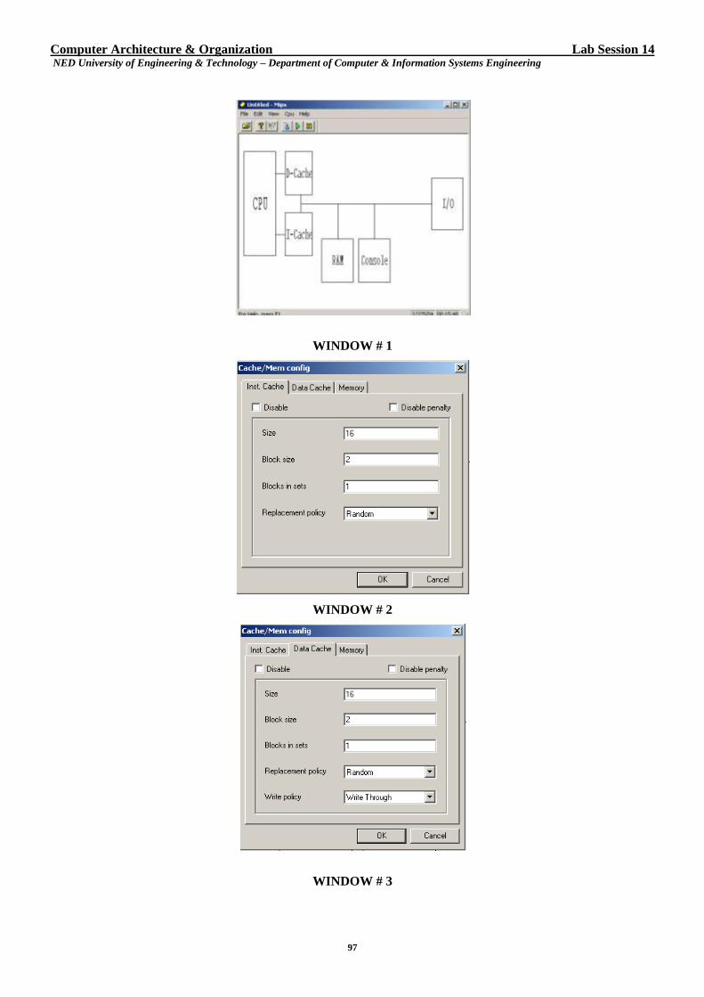
Computer Architecture & Organization Lab Session 14 NED University of Engineering & Technology – Department of Computer & Information Systems Engineering
97
WINDOW # 1
WINDOW # 2
WINDOW # 3
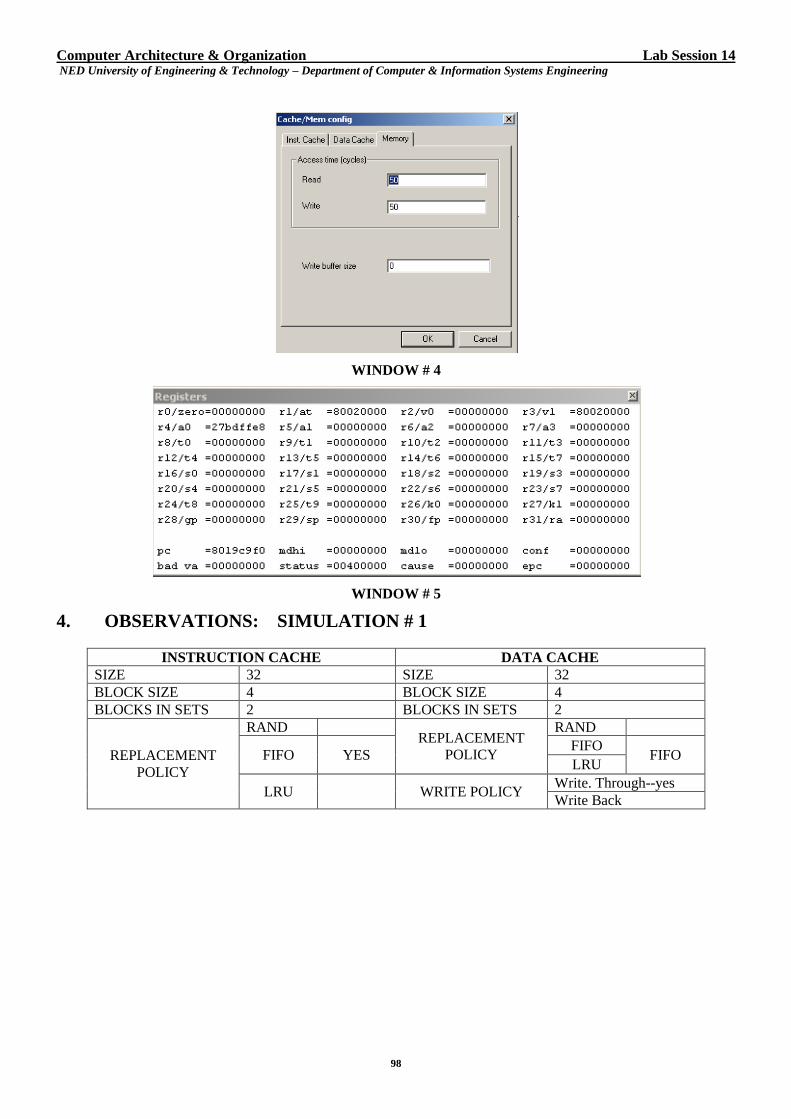
Computer Architecture & Organization Lab Session 14 NED University of Engineering & Technology – Department of Computer & Information Systems Engineering
98
WINDOW # 4
WINDOW # 5
4. OBSERVATIONS: SIMULATION # 1
INSTRUCTION CACHE DATA CACHE
SIZE 32 SIZE 32
BLOCK SIZE 4 BLOCK SIZE 4
BLOCKS IN SETS 2 BLOCKS IN SETS 2
REPLACEMENT
POLICY
RAND REPLACEMENT
POLICY
RAND
FIFO YES FIFO
FIFO LRU
LRU WRITE POLICY Write. Through--yes
Write Back
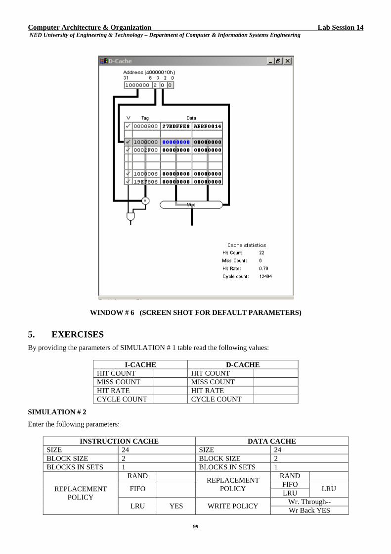
Computer Architecture & Organization Lab Session 14 NED University of Engineering & Technology – Department of Computer & Information Systems Engineering
99
WINDOW # 6 (SCREEN SHOT FOR DEFAULT PARAMETERS)
5. EXERCISES
By providing the parameters of SIMULATION # 1 table read the following values:
I-CACHE D-CACHE
HIT COUNT HIT COUNT
MISS COUNT MISS COUNT
HIT RATE HIT RATE
CYCLE COUNT CYCLE COUNT
SIMULATION # 2
Enter the following parameters:
INSTRUCTION CACHE DATA CACHE
SIZE 24 SIZE 24
BLOCK SIZE 2 BLOCK SIZE 2
BLOCKS IN SETS 1 BLOCKS IN SETS 1
REPLACEMENT
POLICY
RAND REPLACEMENT
POLICY
RAND
FIFO FIFO
LRU LRU
LRU YES WRITE POLICY Wr. Through--
Wr Back YES
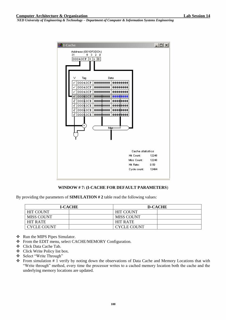
Computer Architecture & Organization Lab Session 14 NED University of Engineering & Technology – Department of Computer & Information Systems Engineering
100
WINDOW # 7: (I-CACHE FOR DEFAULT PARAMETERS)
By providing the parameters of SIMULATION # 2 table read the following values:
I-CACHE D-CACHE
HIT COUNT HIT COUNT
MISS COUNT MISS COUNT
HIT RATE HIT RATE
CYCLE COUNT CYCLE COUNT
Run the MIPS Pipes Simulator.
From the EDIT menu, select CACHE/MEMORY Configuration.
Click Data Cache Tab.
Click Write Policy list box.
Select “Write Through”
From simulation # 1 verify by noting down the observations of Data Cache and Memory Locations that with
“Write through” method, every time the processor writes to a cached memory location both the cache and the
underlying memory locations are updated.
Computer Architecture & Organization Lab Session 14 NED University of Engineering & Technology – Department of Computer & Information Systems Engineering
101
Data Cache Main Memory
Run MIPS Pipes Simulator.
From the EDIT menu, select CACHE/MEMORY Configuration.
Click Data Cache Tab.
Click Write Policy list box.
Select “Write Back”
From simulation # 2 verify by noting down the observations of Data Cache and Memory Locations that
with “Write Back” method, when a write is made to system memory at a location that is currently cached,
the new data is only written to the cache, not actually written to the system memory. Later, if another
memory location needs to use the cache line where this data is stored, it is saved ("written back") to the
system memory and then the line can be used by the new address.
Data Cache Main Memory
Write-back caching saves the system from performing many unnecessary write cycles to the system RAM, which
can lead to noticeably faster execution. Verify this concept using MIPS Pipes Simulator by running simulations and
noting down the write cycles with Write Through Policy and Write Cycles with Write Back Policy.
WRITE CYCLE TIME
Write-Through Policy Write-Back Policy
Computer Architecture & Organization Lab Session 14 NED University of Engineering & Technology – Department of Computer & Information Systems Engineering
102
What is the purpose of UPDATE bit associated with slot when write back policy is used? Use MIPS Pipes
simulator to run the simulation with write back policy. Read the logical value of UPDATE bit and justify your
answer by filling up the following table from MIPS Pipes Simulator outputs.
UPDATE BIT CACHE LINE BLOCK MAIN MEMORY BLOCK
Suppose that we are doing a write operation using MIPS Pipes Simulator and we have cache miss during write. Are
the cache lines updated on a write miss? Use the MIPS Pipes Simulator to run the simulations with write operation
enabled, justify and verify your answer through simulation outputs?
WRITE POLICY
(WT/WB) CACHE SLOT MM BLOCK
Simulation number 1
Simulation number 2
Simulation number 3
Simulation number 4
Computer Architecture & Organization Lab Session 14 NED University of Engineering & Technology – Department of Computer & Information Systems Engineering
103
Simulation number 5
Simulation number 6
Simulation number 7
Simulation number 8
Computer Architecture & Organization NED University of Engineering & Technology – Department of Computer & Information Systems Engineering
104
Lab Session 15
1. OBJECT
Learning Address Translation in Virtual Memory System using MOSS simulator
2. THEORY
The term virtual memory is applied when main memory and secondary storage appear to a user program like a
single, large and directly addressable memory. Traditionally there are three reasons for using virtual memory:
To free user programs from the need to carry out storage allocation and to permit efficient sharing of the
available memory space among different users.
To make programs independent of the configuration and capacity of the physical memory present for their
execution.
To achieve very low access time and cost per bit that are possible with a memory hierarchy.
When virtual memory is used, the Memory Management Unit (MMU) within the computer translates the virtual
memory address generated by the processor into either:
the address of a real memory location (the physical memory address) which refers to a real memory location
within the computer's physical memory to hold that memory item and the memory reference operation is
completed, or
an indication that the desired memory item is not currently resident in main memory. In this case, the operating
system is invoked to swap sections of information between the physical memory and the disk.
2.1 PAGING
One technique to implement virtual memory is paging. Here the memory is partitioned into fixed size chunks called
page frames and each process is also divided into fixed size chunks of same size called pages. Then the operating
system decides which pages of the program are to be kept in physical memory page frames. The operating system
also maintains the translation tables which provide the mappings between virtual and physical addresses, for use by
the MMU. In most computers, these translation tables are stored in physical memory. Therefore, a virtual memory
reference might actually involve two or more physical memory references: one to obtain the needed address
translation from the page tables, and a final one to actually do the memory reference. To minimize the performance
penalty of address translation, most modern CPUs include an on-chip MMU, and maintain a table of recently used
physical-to-virtual address translations, called a Translation Lookaside Buffer, or TLB.
2.2 MOSS SIMULATOR DESCRIPTION
For using MOSS simulator following files are important:
The Command File
The command file for the simulator specifies a sequence of memory instructions to be performed. Each instruction
is either a memory READ or WRITE operation, and includes a virtual memory address to be read or written.
Depending on whether the virtual page for the address is present in physical memory, the operation will succeed,
or, if not, a page fault will occur.
2.2.1 Operations on Virtual Memory
There are two operations one can carry out on pages in memory: READ and WRITE. The format for each
command is
Operation address Or Operation random
Where operation is READ or WRITE, and address is the numeric virtual memory address, optionally preceded by
one of the radix keywords bin, oct, or hex. If no radix is supplied, the number is assumed to be decimal. The
keyword random will generate a random virtual memory address (for those who want to experiment quickly)
rather than having to type an address.
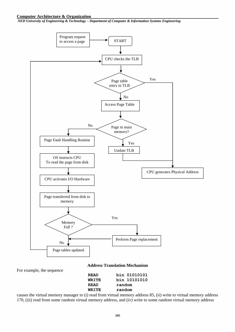
Computer Architecture & Organization NED University of Engineering & Technology – Department of Computer & Information Systems Engineering
105
Address Translation Mechanism
For example, the sequence READ bin 01010101
WRITE bin 10101010
READ random
WRITE random
causes the virtual memory manager to (i) read from virtual memory address 85, (ii) write to virtual memory address
170, (iii) read from some random virtual memory address, and (iv) write to some random virtual memory address
START Program request
to access a page
CPU checks the TLB
Page table
entry in TLB
Access Page Table
Page in main
memory?
No
No
Update TLB
Yes
Yes
CPU generates Physical Address
Page Fault Handling Routine
OS instructs CPU
To read the page from disk
CPU activates I/O Hardware
Memory
Full ?
Page transferred from disk to
memory
Perform Page replacement
Yes
Page tables updated
No
Computer Architecture & Organization NED University of Engineering & Technology – Department of Computer & Information Systems Engineering
106
Sample Command File
The "commands" input file looks like this:
// enter READ/WRITE commands into this file
// READ
// WRITE
READ bin 100
READ 19
WRITE hex CC32
READ bin 100000000000000
READ bin 100000000000000
WRITE bin 110000000000001
WRITE random
The Configuration File
The configuration file memory.conf is used to specify the initial content of the virtual memory map (which
pages of virtual memory are mapped to which pages in physical memory) and provide other configuration
information, such as whether operation should be logged to a file.
Setting up the Virtual Memory Map
The memset command is used to initialize each entry in the virtual page map. The command memset is
followed by six integer values:
a) The virtual page # to initialize
b) The physical page # associated with this virtual page (-1 if no page assigned)
c) If the page has been read from (R) (0=no, 1=yes)
d) If the page has been modified (M) (0=no, 1=yes)
e) The amount of time the page has been in memory (in ns)
f) The time since the last modification of page in memory (in ns)
The first two parameters define the mapping between the virtual page and a physical page, if any. The last four
parameters are values that might be used by a page replacement algorithm.
For example, memset 34 23 0 0 0 0
specifies that virtual page 34 maps to physical page 23, and that the page has not been read or modified.
Please note that:
Each physical page should be mapped to exactly one virtual page.
The number of virtual pages is fixed at 64 (0...63).
The number of physical pages cannot exceed 64 (0...63).
If a virtual page is not specified by any memset command, it is assumed that the page is not mapped.
Other Configuration File Options
There are a number of other options which can be specified in the configuration file. These are summarized in
the table below.
Keyword Values Description
enable_logging true/false
Whether logging of the operations should be enabled. If logging is
enabled, then the program writes a one-line message for each READ or
WRITE operation. By default, no logging is enabled. See also the
log_file option.
Log_file trace-file-name
The name of the file to which log messages should be written. If no
filename is given, then log messages are written to stdout. This option
has no effect if enable_logging is false or not specified.
Computer Architecture & Organization NED University of Engineering & Technology – Department of Computer & Information Systems Engineering
107
pagesize np
The size of the page in bytes as a power of two. This can be given as a
decimal number which is a power of two (1, 2, 4, 8, etc.) or as a power
of two using the power keyword. The maximum page size is
67108864 or 226. The default page size is power 26.
address radix n
The radix in which numerical values are displayed. The default radix is
2 (binary). You may prefer radix 8 (octal), 10 (decimal), or 16
(hexadecimal).
The Output File
The output file contains a log of the operations since the simulation started (or since the last reset). It lists the
command that was attempted and what happened as a result. You can review this file after executing the
simulation. The output file contains one line per operation executed. The format of each line is:
Command address ... status
where, command is READ or WRITE, address is a number corresponding to a virtual memory address, and
Status is okay or page fault.
Sample Output
The output "trace file" looks something like this:
READ 4 ... okay
READ 13 ... okay
WRITE 3acc32 ... okay
READ 10000000 ... okay
READ 10000000 ... okay
WRITE c0001000 ... page fault
WRITE 2aeea2ef ... okay
Sample Configuration File
// memset virt page # physical page # R (read from) M (modified)
inMemTime (ns) lastTouchTime (ns)
memset 0 0 0 0 0 0
memset 1 1 0 0 0 0
memset 2 2 0 0 0 0
memset 3 3 0 0 0 0
memset 4 4 0 0 0 0
memset 5 5 0 0 0 0
memset 6 6 0 0 0 0
memset 7 7 0 0 0 0
memset 8 8 0 0 0 0
memset 9 9 0 0 0 0
memset 10 10 0 0 0 0
memset 11 11 0 0 0 0
memset 12 12 0 0 0 0
memset 13 13 0 0 0 0
memset 14 14 0 0 0 0
memset 15 15 0 0 0 0
memset 16 16 0 0 0 0
memset 17 17 0 0 0 0
memset 18 18 0 0 0 0
memset 19 19 0 0 0 0
memset 20 20 0 0 0 0
memset 21 21 0 0 0 0
memset 22 22 0 0 0 0
Computer Architecture & Organization NED University of Engineering & Technology – Department of Computer & Information Systems Engineering
108
memset 23 23 0 0 0 0
memset 24 24 0 0 0 0
memset 25 25 0 0 0 0
memset 26 26 0 0 0 0
memset 27 27 0 0 0 0
memset 28 28 0 0 0 0
memset 29 29 0 0 0 0
memset 30 30 0 0 0 0
memset 31 31 0 0 0 0
// enable_logging 'true' or 'false'
// When true specify a log_file or leave blank for stdout
Enable_logging true
// log_file <FILENAME>
// Where <FILENAME> is the name of the file you want output
// to be print to.
log_file trace file
// page size, defaults to 2^14 and cannot be greater than 2^26
// pagesize <single page size (base 10)> or <'power' num (base
2)>
pagesize 16384
// addressradix sets the radix in which numerical values are displayed
// 2 is the default value
// addressradix <radix>
addressradix 16
// numpages sets the number of pages (physical and virtual)
// 64 is the default value
// numpages must be at least 2 and no more than 64
// numpages <num>
numpages 64
3. PROCEDURE
SIMULATION # 1
a) Modify the commands file and enter the following sequence of commands into it.
READ bin 010
READ bin 011
READ 19
WRITE hex CC32
WRITE hex BC12
WRITE hex AB05
READ bin 100000000000000
READ bin 100000000000000
WRITE bin 110000000000001
WRITE random
b) Run MOSS simulator and press reset button .Observe the output.
c) Trace file will be generated. Note down the log of operations (in the table on the next page) since simulation
started.
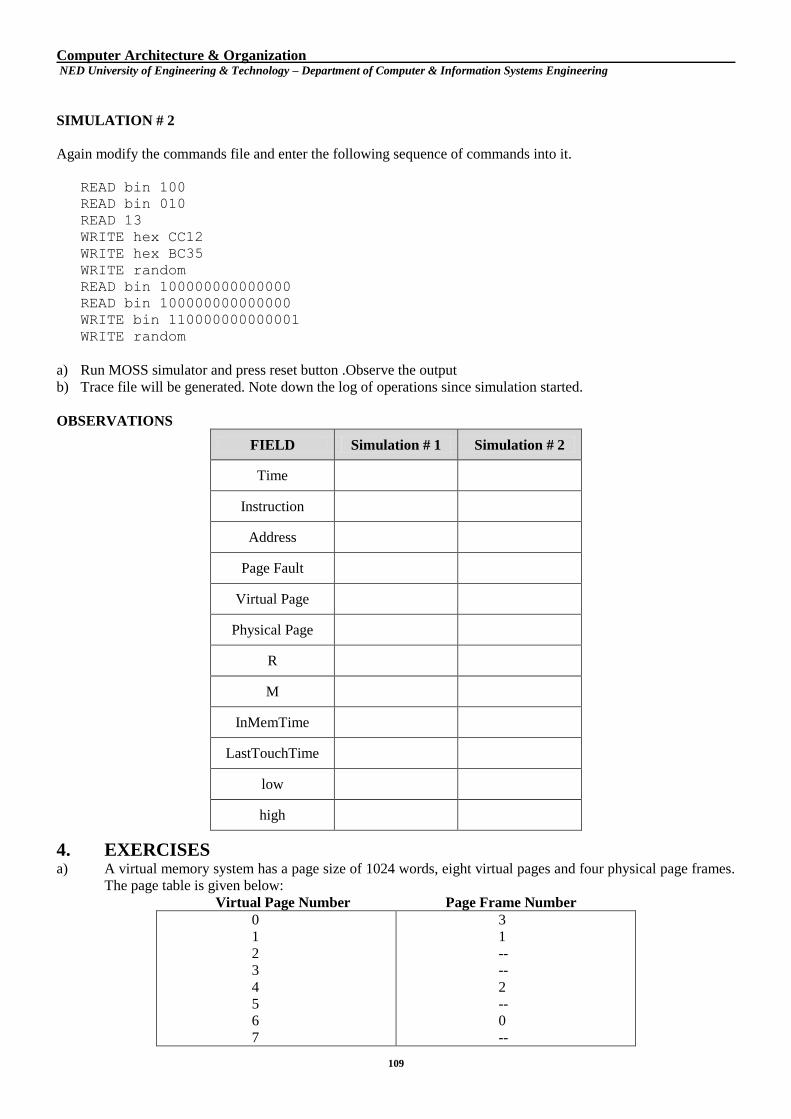
Computer Architecture & Organization NED University of Engineering & Technology – Department of Computer & Information Systems Engineering
109
SIMULATION # 2
Again modify the commands file and enter the following sequence of commands into it.
READ bin 100
READ bin 010
READ 13
WRITE hex CC12
WRITE hex BC35
WRITE random
READ bin 100000000000000
READ bin 100000000000000
WRITE bin 110000000000001
WRITE random
a) Run MOSS simulator and press reset button .Observe the output
b) Trace file will be generated. Note down the log of operations since simulation started.
OBSERVATIONS
FIELD Simulation # 1 Simulation # 2
Time
Instruction
Address
Page Fault
Virtual Page
Physical Page
R
M
InMemTime
LastTouchTime
low
high
4. EXERCISES a) A virtual memory system has a page size of 1024 words, eight virtual pages and four physical page frames.
The page table is given below:
Virtual Page Number Page Frame Number
0
1
2
3
4
5
6
7
3
1
--
--
2
--
0
--
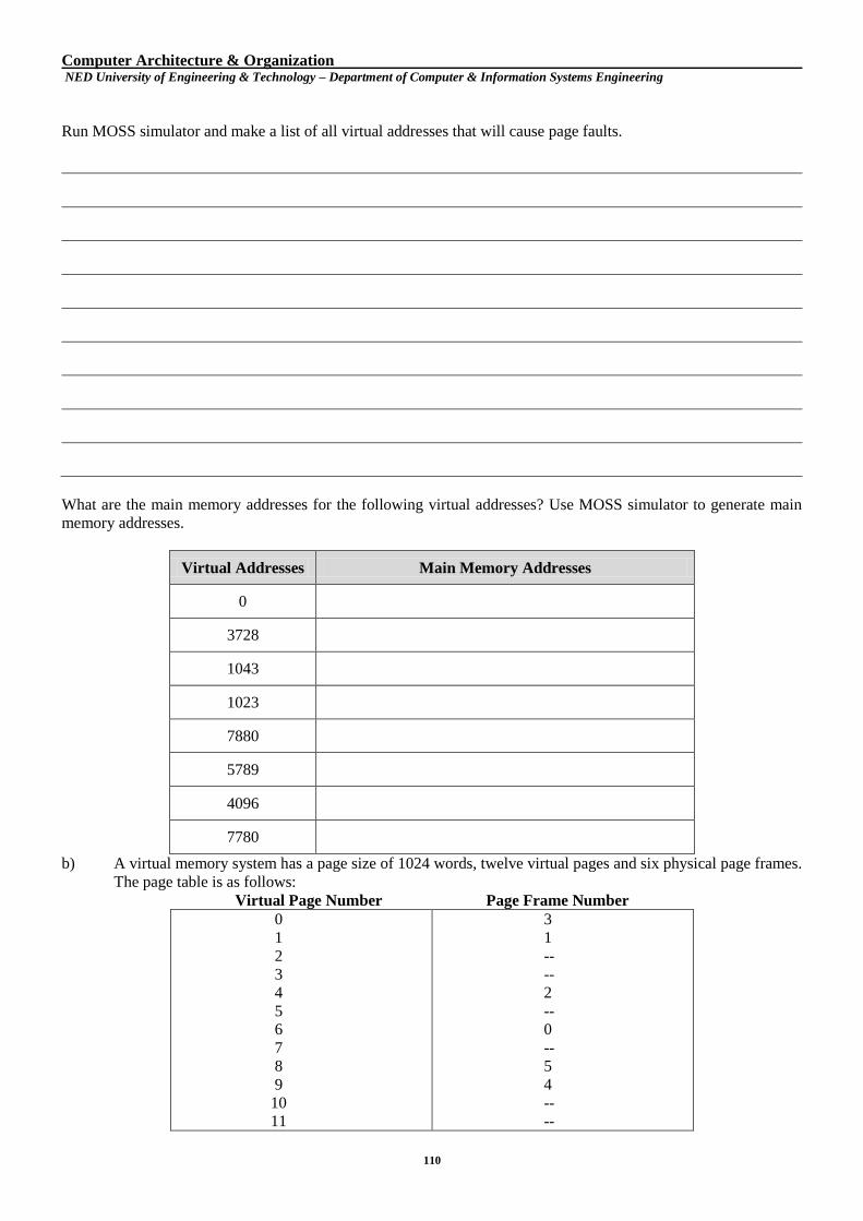
Computer Architecture & Organization NED University of Engineering & Technology – Department of Computer & Information Systems Engineering
110
Run MOSS simulator and make a list of all virtual addresses that will cause page faults.
What are the main memory addresses for the following virtual addresses? Use MOSS simulator to generate main
memory addresses.
Virtual Addresses Main Memory Addresses
0
3728
1043
1023
7880
5789
4096
7780
b) A virtual memory system has a page size of 1024 words, twelve virtual pages and six physical page frames.
The page table is as follows:
Virtual Page Number Page Frame Number
0
1
2
3
4
5
6
7
8
9
10
11
3
1
--
--
2
--
0
--
5
4
--
--
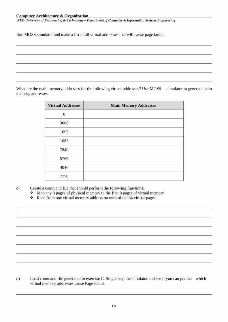
Computer Architecture & Organization NED University of Engineering & Technology – Department of Computer & Information Systems Engineering
111
Run MOSS simulator and make a list of all virtual addresses that will cause page faults.
What are the main memory addresses for the following virtual addresses? Use MOSS simulator to generate main
memory addresses.
Virtual Addresses Main Memory Addresses
0
3008
1093
1083
7840
5769
4046
7770
c) Create a command file that should perform the following functions:
Map any 8 pages of physical memory to the first 8 pages of virtual memory
Read from one virtual memory address on each of the 64 virtual pages.
d) Load command file generated in exercise C. Single step the simulator and see if you can predict which
virtual memory addresses cause Page Faults.
Computer Architecture & Organization NED University of Engineering & Technology – Department of Computer & Information Systems Engineering
112
e) Which page replacement algorithm is being used by the MOSS simulator?
Computer Architecture & Organization NED University of Engineering & Technology – Department of Computer & Information Systems Engineering
113
References:
R. C. Detmer, Introduction to 80x86 Assembly Language and Computer Architecture, 2nd
. ed., Sudbury:
Jones and Bartlett, 2010.
K. R. Irvine, Assembly Language for x86 Processors, 6th. ed., Upper Saddle River: Prentice Hall, 2011.
IA-32 Intel® Architecture Software Developer’s Manual, Intel Corporation, Mount Prospect, IL, 2002